
Create successful ePaper yourself
Turn your PDF publications into a flip-book with our unique Google optimized e-Paper software.
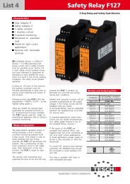
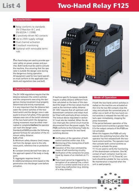
List 4<strong>Two</strong>-<strong>Hand</strong> <strong>Relay</strong> <strong>F125</strong>Characteristics■ <strong>Relay</strong> conforms to standardsEN 574section III C andEN 60204-1 (1998)■ 2 positively-driven NO contacts■ Up to 230V supply voltage■ Dual channel activation■ Crossfault monitoring■ Optional with removable terminals<strong>Two</strong>-hand relays are used to provide operatorsafety on power presses and punches.Both hands must be used to activatethe machine, thus ensuring that the operatoris outside the danger zone duringthe dangerous closing operation.All equipment used for two-hand operationmust conform to the applicable standardsand regulations (see overleaf).CharacteristicsThe ZH 1/456 regulations require that thedistance between the control switchesand the components executing the dangerousclosing movement must properlydetermined and strictly maintained.It is very important that the distance betweenthe control switches of the twohandswitch and the danger zone is adequateto ensure full safety. If the operatorreleases even one of the switch elementsof the two-hand switch the dangerousclosing movement must be either interruptedor completed before the operatorcan reach the danger zone.Standard prEN999 provides the followinggeneral formula for calculation of the minimumsafety distance:S=K x T+CS: Minimum safety distance (mm) measuredfrom the danger zone to the referencepoint, reference line or protectionareaK: Constant (mm/s) derived from data onthe approach speed of the body or bodypartsT: Aggregate response time (s)C: Additional distance (mm) based on thepenetration into the danger zone beforeactivation.If machine-specific European standardsrequire a safety distance different fromthat calculated on the basis of this standardthe larger of the two values must beused as the minimum safety distance.ZH 1/457 requires that all upstream anddownstream contactors and relays mustbe fitted with positively-driven contacts.The lockout device stipulated in section3.7 must also be installed. When the deviceinterrupts the control circuit must bedisconnected from the power supply. The<strong>F125</strong> conforms to the following Trade Associationrequirements for two-handswitching devices:■ Verification of the operation of bothcontrol switches within max. 0.5s.■ Monitoring of the closing time of bothcontrol switches.■ Execution of the close command bymeans of self-monitoring circuitry.■ Verification of the contactors for presstravel by means of an interlock on Y1-Y2.■ Press travel cannot be triggered by interruptionof an external line, a shortcircuit in a control switch line or an internalrelay malfunction (e.g. stickingof a relay contact).Mode of OperationIf both the two-hand control switches installedon the machine are activated within0.5s the two NO contacts close therelay and activate the connected press. Ifeither one or both of the two-hand controlswitches is released the two NO contactsopen immediately, stopping thepress movement.If the period between operation of thetwo-hand control switches is greater than0.5s the output contacts of the <strong>F125</strong> arenot activated.When this happens the <strong>F125</strong> will onlyexecute the switching function after theoperator has first released both the twohandcontrol switches. The operator mustthen activate both control switches asnormal to activate the press.Y1-Y2 are used to verify the functioningof the downstream contactors. One NCcontact of each contactor must be connectedin series to Y1-Y2.Those NC contactsshould be suitable for low currents.No maintenance is required when theunit is used properly.Automation Control Components
<strong>Two</strong>-<strong>Hand</strong> <strong>Relay</strong> <strong>F125</strong>The right to makechanges is reservedWiring DiagramWiring VariationL1NA1(+)S1S11 S12 S13 Y1 Y2 13 23+24VDC–A1(+)S 1 S 1S11Y1Y2S21A2(–)Pushbuttonsdirectly connectedto the 24VDC powersupply.(reduced wiring)A1 S11 S12 S13 X1 X2 13 23+ –– +S21 S22 S23 A2 14 24S21 S22 S23 A2(–)14 24Dimensional Diagram9922.5DIN rail mounting toEN 50022-35 x 7.5(all dimensions in mm)S2114.5Technical DataStandards and RegulationRated voltage230 / 115 / 24VAC; 30 / 24VDCVoltage range 0.8 to 1.1 x rated voltage, (0.8 to 1 x at 30V type)*Power consumption Approx. 2WRated insulation voltage 250VCreep distance and gaps Overvoltage category III, Pollution level 2 to DIN VDE 0110-1 (04/97)Test voltage2.5kVAmbient temperature -5 ˚C to +55 ˚CMode of protection Terminals IP 20, IP 40 casing to DIN VDE 0470-1Switching capacity 250VAC; 1250VA / 24VDC; 120W,preferably with spark arrestThermic current Ith Max. 1 x 6A or 2 x 4AUtilisation category AC-15 250V 5A; DC-13 24V 3AResponse timeApprox. 20msRelease timeApprox. 20msRecovery time> 500msLoad via hand- pushbuttoncontactsOutput contactsMechanical lifetimeSwitch materialTerminalsN/O contacts 25V / 17mAN/C contacts 30V / 11mA2 N/O safety contacts10 7 switching cyclesAgSnO 2 , 0.5µ AuTerminal box with wire protectionLine cross section 2.5 mm 2Control circuitApprox. 24VDCContact protection Screwed-type fuse max. 6A slow blowAuto circuit breaker max. C10A quick breakWeight260g; 24V type: 210gEN 292-1(11/91)EN 292-2(06/95)EN 954-4(03/97)EN 894-1(04/97)EN 999(12/98)EN 1050(01/97)EN 602044(11/98)EN 574(02/97)ZH 1/456(02/78)ZH 1/457(02/78)EN 692 (96)EN 693 (95)Safety of MachinesTerms, GeneralDesign GuidelinesSafety of MachinesSafety-relevant ControlDevice ComponentsSafety of MachinesErgonomic Requirementsfor the Design of Displaysand ActuatorsSafety of Machines<strong>Hand</strong> / Arm SpeedSafety of MachinesRisk EvaluationSafety of MachinesElectrical Equipmentof MachinesSafety of Machines<strong>Two</strong>-hand CircuitsTrade AssociationRegulations [Berufsgenossenschaft]Mechanical Presses SafetyHydraulic Presses SafetyModels and Ordering DataSupply voltage 230VAC 115VAC 24VAC 24VDC 30VDC *Type <strong>F125</strong>Order-No.Fixed terminals 075 00015 075 00016 075 00017 075 00018 075 00019Removable terminals 075 00032 075 00033 075 00034 075 00035 075 00036* 30VDC = Bridge rectifier supply, not filtered<strong>TESCH</strong> <strong>GmbH</strong>, AutomationControl ComponentsGraefrather Straße 124D-42329 WuppertalPhone +49-202-73 91-0Fax +49-202-73 91-115http://www.tesch.deeMail: vertrieb-ak@tesch.deGermany