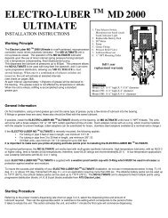
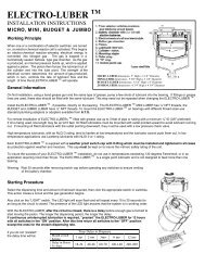
Starting ProcedureReferring to the proper model’s dispensing rate chart on page 3 or 4, select the dispensing time and amount oflubricant required. Then set the appropriate switch or switches to the setting which corresponds to the period of timeit takes to empty the unit. This action activates the unit, and within 1 minute the first cycle will commence dispensing.Operating ProcedureIf it is desired to increase or decrease the lubricant dispensing rate during operations, simply click the switch or switches in use to OFF,Then click on the new switch setting for the revised rate.To turn OFF the <strong>JACK</strong>-LUBER TM set all switches to OFF.The <strong>JACK</strong>-LUBER TM can be removed at any time without lubricant discharge.Switch 7 is the purge switch. If your bearing requires an immediate shot of grease, turn ON switch 7. When the <strong>JACK</strong>-LUBER TM startsoperating, turn switch 7 OFF. The <strong>JACK</strong>-LUBER TM will run for approximately 1-3 minutes. If you require more purging, repeat the procedure.While the unit is operational, the LED light will flash green once every 20 seconds, indicating the electronics are functioning properly.During the pump cycle, the LED will flash green approximately once per second, indicating that the pump is turning and pumping grease.If there is a problem with the unit it will be indicated by the Red or Blue LED flashing every 20 seconds as follows:• 1 red flash indicates that the unit has an internal limit switch error and is running in the failsafe mode.(limit switch is used to control the dispensed volume, if it fails, the unit goes into a “failsafe” mode to dispense by time)• 2 red flashes indicate that the battery is low and must be replaced shortly.• 2 blue flashes indicate that the unit is paused via the remote control option.PowerThe battery packs should be replaced every time a new grease cartridge is installed. Please note that battery life is affected by temperature,bearing backpressure and unit setting. Life expectancy is based on standard installation. To change the battery pack, remove the top ring,unplug and remove the old battery pack, and then install and plug in the new battery pack. It is recommended that you have a spare batterypack to avoid a prolonged outage. The battery packs, complete with connectors, may be purchased directly from the factory.Comparison ChartOptional alternate power sources are available, please consult the factory or your salesperson.This chart compares the lubricant output rate of the <strong>JACK</strong>-LUBER TM with several common manual lubrication schedules. The<strong>JACK</strong>-LUBER TM switch settings indicated will provide comparable lubrication to that of the manual practice shown.Do not over-lubricate bearing. Some typical settings follow, see the charts on the next page for all settings.Manual LubricationSchedule<strong>JACK</strong> Model 125 <strong>JACK</strong> Model 250Unit Life Switch Setting Unit Life Switch SettingDaily lubrication 3 – 4 strokes2–3 day lubrication3 – 4 strokesWeekly lubrication8 – 10 strokesBi-weekly lubrication8 –10 strokesMonthly lubrication8 – 10 strokesBi-monthly lubrication8 – 10 strokes1 month(30 days)2 months(60 days)3 months(90 days)6 months(180 days)12 months(360 days)24 months(720 days)2 months(60 days)4 months(120 days)6 months(180 days)12 months(360 days)24 months(720 days)
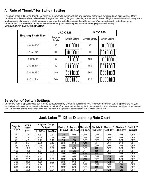
A “Rule of Thumb” for Switch SettingThis chart offers a “Rule for Thumb” for selecting appropriate switch settings and lubricant output rate for some basic applications. Manyvariables must be considered when determining the best setting for your operating environment. Areas of high contamination and heavy waterwashout generally require a slight increase in lubricant flow rate. Because of the wide number of variables found in actual operatingenvironments, this chart should only be considered as a guide in making the selection of the proper switch setting.ALWAYS AVOID OVER-LUBRICATING.Bearing Shaft SizeDays toEmpty<strong>JACK</strong> 125 <strong>JACK</strong> 250Switch Setting Days to Empty Switch Setting4 ¾” to 6 ½” 15 304” to 4 ¾” 30 603 ¼” to 4” 60 1202 ¾” to 3 ¼” 90 1802 ¼” to 2 ¾” 180 3601 ¾” to 2 ¼” 360 720Selection of Switch SettingsOne stroke from a typical grease gun is equal to approximately one cubic centimetre (cc). To select the switch setting appropriate for yourapplication look down the column for the desired output of lubricant, remembering that 1 cc is equal to approximately one stroke from a greasegun. The switch setting for your selection is shown in the right most columns labelled Switch1 to Switch7.Days toEmptyJack-<strong>Lube</strong>r TM 125 cc Dispensing Rate ChartCycleTimeApprox. DailyOutput(hrs) in CC’s in CI’sSwitch 1(15 day)Switch 2(30 day)Switch 3(60 day)Switch 4(120 day)Switch 5(240 day)Switch 6(480 day)Switch 7(purge)15 1.4 8.37 0.51 ON OFF OFF OFF OFF OFF OFF30 2.9 4.19 0.26 OFF ON OFF OFF OFF OFF OFF45 4.3 2.79 0.17 ON ON OFF OFF OFF OFF OFF60 5.7 2.09 0.13 OFF OFF ON OFF OFF OFF OFF90 8.6 1.40 0.09 OFF ON ON OFF OFF OFF OFF120 11.5 1.05 0.06 OFF OFF OFF ON OFF OFF OFF150 14.3 0.84 0.05 OFF ON OFF ON OFF OFF OFF180 17.2 0.70 0.04 OFF OFF ON ON OFF OFF OFF240 22.9 0.52 0.03 OFF OFF OFF OFF ON OFF OFF300 28.7 0.42 0.03 OFF OFF ON OFF ON OFF OFF360 34.4 0.35 0.02 OFF OFF OFF ON ON OFF OFF480 45.8 0.26 0.02 OFF OFF OFF OFF OFF ON OFF600 57.4 0.21 0.01 OFF OFF OFF ON OFF ON OFF720 68.8 0.17 0.01 OFF OFF OFF OFF ON ON OFF