Article 7 Deep Space 1 Navigation: Extended Missions
Article 7 Deep Space 1 Navigation: Extended Missions
Article 7 Deep Space 1 Navigation: Extended Missions

You also want an ePaper? Increase the reach of your titles
YUMPU automatically turns print PDFs into web optimized ePapers that Google loves.
DESCANSO Design and Performance Summary Series<strong>Article</strong> 7<strong>Deep</strong> <strong>Space</strong> 1<strong>Navigation</strong>: <strong>Extended</strong> <strong>Missions</strong>Brian KennedyShyam BhaskaranJ. Edmund RiedelMike WangJet Propulsion LaboratoryCalifornia Institute of TechnologyPasadena, CaliforniaNational Aeronautics and<strong>Space</strong> AdministrationJet Propulsion LaboratoryCalifornia Institute of TechnologyPasadena, CaliforniaSeptember 2003
This research was carried out at theJet Propulsion Laboratory, California Institute of Technology,under a contract with theNational Aeronautics and <strong>Space</strong> Administration.
DESCANSO DESIGN AND PERFORMANCE SUMMARY SERIESIssued by the <strong>Deep</strong>-<strong>Space</strong> Communications and <strong>Navigation</strong> SystemsCenter of ExcellenceJet Propulsion LaboratoryCalifornia Institute of TechnologyJoseph H. Yuen, Editor-in-ChiefPreviously Published <strong>Article</strong>s in This Series<strong>Article</strong> 1—“Mars Global Surveyor Telecommunications”Jim Taylor, Kar-Ming Cheung, and Chao-Jen Wong<strong>Article</strong> 2—“<strong>Deep</strong> <strong>Space</strong> 1 Telecommunications”Jim Taylor, Michela Muñoz Fernández, Ana I. Bolea Alamañac, and Kar-Ming Cheung<strong>Article</strong> 3—“Cassini Telecommunications”Jim Taylor, Laura Sakamoto, and Chao-Jen Wong<strong>Article</strong> 4—“Voyager Telecommunications”Roger Ludwig and Jim Taylor<strong>Article</strong> 5—“Galileo Telecommunications”Jim Taylor, Kar-Ming Cheung, and Dongae Seo<strong>Article</strong> 6—“Odyssey Telecommunications”Andre Makovsky, Andrea Barbieri, and Ramona Tungiii
List of TablesTable 2-1. Entries in image processing configuration array........................................................... 5Table 2-2. Image routing and handling definitions......................................................................... 7Table 3-1. A thrust profile used during deterministic thrusting.................................................... 14Table 3-2. North–south thrust attitudes used to maintain a converged “ballistic” trajectory....... 15Table 4-1 Attitude losses, time ranges, and causes....................................................................... 19Table 6-1. Doppler weights used during conjunction, by pass..................................................... 26Table 10-1. Doppler-based thrust measurements.......................................................................... 38vii
ForewordThis Design and Performance Summary Series, issued by the <strong>Deep</strong> <strong>Space</strong>Communications and <strong>Navigation</strong> Systems Center of Excellence (DESCANSO), is a companionseries to the DESCANSO Monograph Series. Authored by experienced scientists and engineerswho participated in and contributed to deep-space missions, each article in this seriessummarizes the design and performance for major systems such as communications andnavigation, for each mission. In addition, the series illustrates the progression of system designfrom mission to mission. Lastly, it collectively provides readers with a broad overview of themission systems described.Joseph H. YuenDESCANSO Leaderviii
PrefaceThis article will describe the means by which JPL navigators determined and controlledthe trajectory of the <strong>Deep</strong> <strong>Space</strong> 1 (DS1) spacecraft during the course of its extended missions.It is worth noting that during most of the extended missions, DS1 was a dysfunctionalspacecraft. This was due to the fact that the sole source of stellar reference used by the attitudecontrol system (ACS) was the science camera. As such, this limited the attitudes that could bemaintained by DS1 and constrained its operations leading up to and during the encounter withcomet Borrelly. The impact of these constraints on navigation during the extended missions andtheir workarounds will be discussed in this article.It is hoped that this article can be used as a source that documents the navigationchallenges (and rewards) of DS1 and that future navigators can use it to gain insight into theimplementation of new methods of guiding spacecraft towards scientifically rich encounters.ix
AcknowledgementsThe authors would like to thank many members of the NASA Community, whose effortsand inputs made the DS1 mission a very rewarding and successful experience: Tim McElrath,Don Han, and Marc Ryne for developing the DS1 radio navigation strategies during the primarymission; Marc Rayman, the DS1 Mission Manager, for having faith in the flight team to makethe extended mission a success; Bob Werner, for developing ground tools that greatly simplifiedoperations; Steve Collins, Tony Vanelli, Sam Sirlin, Sanjay Joshi, and Jim Alexander for theirattitude control expertise; Jim Taylor, the DS1 Telecommunications Lead, for his inputs and forhis tireless telecommunications support; the DS1 flight team, the DS1 flight controllers, and thepersonnel of the DSN facilities at Goldstone, Madrid, and Canberra.x
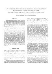
<strong>Deep</strong> <strong>Space</strong> 1 2Fig. 1-1. The DS1 spacecraft.Following replacement of the SRU, a new low-thrust trajectory was developed. Thistrajectory required the use of near continuous IPS thrust in order to maintain spacecraft attitudeusing IPS thrust vector control (TVC) instead of the Reaction Control System (RCS) for attitudecontrol. This reduced the usage of hydrazine (the fuel used by the RCS) from tens of grams perday to grams per day. This need to conserve hydrazine was the result of expending largequantities of hydrazine during the extended safehold and of maintaining the spacecraft in anEarth-pointed configuration for high-rate data passes without the use of the SRU. In the absenceof an SRU, the flight team devised a complex technique that allowed them to maintain thespacecraft in an Earth-pointed attitude. This technique is described in [8] and [2].The replacement of the SRU with the MICAS camera required changes to the attitudecruise navigation techniques and the flight software. Since scheduling optical navigationactivities would increase the risk of losing celestial inertial reference, the optical OrbitDetermination (OD) capabilities of the AutoNav could not be used during cruise, so radiometricOD would be required. Optical OD would still be used to support the approach phase of theencounter. The encounter with Borrelly required modifications to the tracking software thatenabled it to estimate the errors within the inertial measurement unit (IMU) and to provideupdated pointing to attitude control system (ACS) during the encounter.Fortunately, the flight team was able to successfully operate the spacecraft in thisdegraded condition, and complete the planned flyby of comet Borrelly on September 22 nd ,2001—exceeding the scientific objectives 2 of the encounter.2 In addition to returning comet spectroscopy and charged-particle measurements, the science team asked the flightteam to return a 50-pixel image of the nucleus. An image of greater than 170 pixels was returned.
Section 2Operations without an SRUFollowing the failure of the SRU in November 1999, normal spacecraft operations cameto a halt. Maintaining a known attitude that would allow the spacecraft to continue thrusting onits mission trajectory was no longer possible, nor was it capable of accurately pointing itsnavigation/science camera during imaging opportunities such as optical navigation sessions orcomet encounters.Without the SRU, the ACS lost the only instrument capable of providing it with inertialattitude quaternions every 0.25 seconds. This left the ACS with an IMU (the solid-state gyro)and a coarse (0.5 degree) Sun Sensor Assembly (SSA). The IMU was effective at providingspacecraft rate information, which could be integrated to provide attitude, but it was too noisyand unstable to provide a reasonable attitude estimate for more than a few hours. The SSA couldbe used to keep an accurate fix on the direction to the Sun, but not the spacecraft rotation aroundthat vector. Therefore, measurements from these systems alone would not enable the ACS tosustain a full 3-axis attitude estimate for more than a few hours, far too short to support lengthyIPS thrust arcs. A more detailed description of the SRU anomaly can be found in [2].2.1 SRU-Replacement EffortsAs the only other optical device onboard DS1, the MICAS camera would become thenew de facto star camera. AutoNav would be used to process the MICAS images in order toextract the star locations needed by the ACS. Due to the small usable field of view (FOV) of theMICAS camera (effectively 0.5 × 0.75 degrees, as compared to the 8.8 × 8.8 degree FOV of theSRU [2,3] and magnitude limitations (6.0 or brighter) only a single star would be tracked at agiven time. Another stellar reference would be needed and was readily available asmeasurements from the coarse SSA. Since the MICAS camera and the SSA were pointed alongorthogonal spacecraft axes, their measurements would provide a strong relative geometry withwhich a new ACS could estimate and control the spacecraft attitude. The ACS would also beable to estimate the current biases and drifts within the IMU, which would have to be relied on tomaintain correct inertial attitude during turns. With this in mind, a new attitude estimator and anew image-processing manager were written.The AutoNav system contained substantial image processing capabilities. During thebeginning of the extended mission, work was already underway to develop additional softwarethat would be used during the upcoming comet encounter. This software, affectionately called“the Blobber,” was designed to search through a specified area of a MICAS image and return alist of any contiguous “blobs.” It was expected that these blobs would represent the nucleus ofthe comet, and that additional software could be used to rectify and extract appropriate targetinginformation for the nucleus tracking software (see Sections 8, 9, and 10.) In the context of star4
Operations without an SRU 5identification, it served as a fast means of extracting the pixel and line locations of potential starcandidates that needed to be passed along to the ACS.2.2 The Role of the AutoNav SubsystemIn order to effectively use the AutoNav image processor for the SRU replacement, threenew command and software interfaces were developed. The first one was between ground andthe ACS, the second one was between the ACS and AutoNav, and the third one was between theACS and AutoNav by way of the MICAS camera.It was decided that the old method of configuring AutoNav software by adding newparameter files or expanding old ones would be cumbersome to use [9]. This was due to theexpected high frequency of updates that would be needed in operations. Therefore an ACSstorage facility, called a Parameter Settings (PSET) array, was made use of. Table 2-1 shows theentries in the PSET array used to store information for the main <strong>Navigation</strong> Software Element(the “Nav Task”). ACS PSET arrays are settable by a single ground command. An additionalground command was used to cause the ACS to transfer the array information to the main NavTask. This ACS–<strong>Navigation</strong> interface required an additional queue interface to be added to theNav Task.Table 2-1. Entries in image processing configuration array.Programmatic Labelpix_startpix_endlin_startlin_endceilingfloorceiling_noisyDescriptionColumn at which the search software started looking for stars. This was typically setto pixel 10. Ignoring data that was too close to the edge of an image was preferred,since the optical distortion was quite prevalent (up to several pixels) near the edge ofan image.Column at which the search software stopped looking for stars. This was typicallyset to line 1013 (out of 1023). See pix_start, above.Row at which the search software would start looking for stars in an image. Thiswas typically set to line 300, which allowed the search software to ignore stray lightartifacts that quite literally dominated the images at low Sun cone angles (50 to 90degrees).Row at which the search software stopped looking for stars. This was typically setto line 1013 (out of 1023). See pix_start, above.Maximum pixel signal that would be considered valid star data. This was intendedto be used to filter out saturated pixels that might be the result of cosmic ray strikes.This was set to 4000, out of a maximum signal of 4095. In practice, this sometimesresulted in valid signals from particular bright stars being thrown out by the starsearch software.Minimum pixel signal that would be considered for valid star data. This was the keyto the performance of the star tracking software. This was set to be 40, whichallowed the star search software to ignore the background noise that was prevalent inthe images, even after background processing. This allowed valid, potential starsignals to be sent to the ACS without flooding the ACS Star Identification softwarewith false signals.This was the maximum value for the ceiling (see ceiling, above) used whenbackground processing was not performed. In practice, this was set to 4000, but itwas almost never used in flight.
Operations without an SRU 6floor_noisyblob_boundary_extverbosityacs_filter_widthacs_filter_heightfg_pic_biasThis was the minimum value for the floor (see floor, above) used when backgroundprocessing was not performed. In practice, this was set to 100, but it was almostnever used in flight.Part of the statistical analysis that was performed to identify a star magnitude reliedon a sampling of the background noise. This was used to compute the true signalcoming from the star, minus the background interference. The boundary extensionwas the distance from a star “blob” around which a sample box was circumscribed.The average of pixel values that defined the edges of this box was used as theaverage background value.Setting (or clearing) this allowed the ground operators to turn on (or off) eventreporting during star search processing. This was to allow diagnostic evaluation ofthe performance of the software when necessary.This defined the maximum width of a star signal in theimage, in pixels. In practice, this was set to be 200 pixels. It was intended that thisbe used to filter out large areas that might be stray light artifacts and not true stars.At low cone angles ( 45–50 degrees), large stray light artifacts would show up in themiddle of the image. This filter was an attempt to prevent them from beingmistaken as star signals.This defined the maximum height of a star signal in theimage, in pixels. In practice, this was set to be 100 pixels.See acs_filter_width, above.During picture background processing, a small bias was applied to the foregroundimage before the background image was subtracted. In flight, this was typically setto 10 DN.During tracking operations, the ACS task would initiate an image by directly sendingimage exposure commands to the camera manager, with the request that the images be passed toAutoNav following the exposure. The extended image command interface developed forAutoNav’s use in the primary mission was used, since it allowed for user-defined data to beadded to the header of the resulting image. This user-defined information was used to provideimage handling, routing, and processing information to the AutoNav image processing software,as well as provide needed bookkeeping information to the ACS. The image processing softwarehandled four image types: background images, solo images, and parts one and two of a pair ofimages.When AutoNav received a background image, it was placed in a buffer for laterapplication. The ACS routinely requested that background images be taken every half hour.This was intended to make sure that the background image was replaced often enough to tracksubtle changes in the stray light signature of the MICAS images [9].Image pairs were shuttered back-to-back and sent to AutoNav for processing with theintent that persistent star data would show up in each image, but not transient signals fromcosmic rays or other interference. This would allow the ACS to sort the “wheat from the chaff”and converge on a stable attitude solution. Solo images were requested once the ACS haddecided that it was receiving a consistent, identifiable star signal. Most (over 99 percent) of theimages taken for star tracking purposes were of the solo type.Images could also be of a certain class: background A, background B, or no background.The image class type was used to control whether background processing would be applied to animage before processing. Although it was intended to use “background free” processing as ameans of increasing throughput, in practice this was not necessary. Nearly all images used for
Operations without an SRU 7tracking underwent background processing to remove the static stray light signatures from theMICAS images. Table 2-2 shows the handling definitions and values used during the extendedmission.Table 2-2. Image routing and handling definitions.Name Value DescriptionImage TypeIMAGE_BKG (0x8000) Indicates that this picture is to be stored in the background image bufferfor use in future background processing. This was used as a means ofremoving most of the noise from stray light artifacts. Images of this typewould be ofDIFF_CLASS_A or DIFF_CLASS_B (see Image Class,below).IMAGE_SOLO (0x8001) This is the nominal image type.IMAGE_PART1 (0x8002) This is the first of two back-to-back images. These images are shutteredwithin two seconds of each other as way of letting the ACS staridentification software discard spurious signatures that might be the resultof cosmic ray interference. It also allows it to identify consistent starsignatures, which it needs before declaring that it has locked onto a star.IMAGE_PART2 (0x8003) This is the second of two back-to-back images. See IMAGE_PART1,above.Image ClassDIFF_NOTHING (0x8000) Images of this class did not undergo background processing. In practice,pictures of this class were rarely shuttered.DIFF_CLASS_A (0x8001) Images of this class were to undergo background processing using abackground image that was of class “A.” If the image in the backgroundwas not of type A, the ACS would be alerted, and a new backgroundimage would be shuttered.DIFF_CLASS_B (0x8002) Undergo background processing with class “B”. See DIFF_CLASS_A,above.2.3 Operational ConstraintsThe key to effective use of the new software was the careful preselection of a knownreference star, also known as a “lock star”. With a priori knowledge of where the spacecraftshould point the camera for Earth communications or for IPS burn arcs, suitable stars werechosen from a star catalog. These stars were dubbed “Earth stars” and “Thrustars, ” respectively.Over the course of the extended mission, it was noted that stars of magnitude 4.0 or brighterwere ideal for use as reference stars. Stars of 5th or 6th magnitude could also be used, if theywere a “red” spectral type, such as a class-M, since charged couple detectors (CCDs) tend to bemore sensitive to red. The weak signal from stars less than 6th magnitude could not be relied onfor tracking purposes, as the tracking software required consistent inputs to maintain a reliablelock. Due to these magnitude constraints, stars at suboptimal locations occasionally had to beused for inertial attitude reference, with a corresponding loss in thrusting effectiveness forThrustars and a reduced communications bandwidth capability for Earth stars. Once a referencestar was selected, its inertial right ascension and declination would be told to the new ACS,which could then use the reported star location within the frame of the image to finely tune itsestimate of the attitude.
Operations without an SRU 82.4 BootstrappingSince DS1 was now effectively equipped with a single-star tracker instead of a fullstarfieldtracker, getting the spacecraft into a known attitude became a proverbial “chicken or theegg” problem. Without a known inertial attitude, the spacecraft could not be commanded to pointat a known reference star for tracking purposes. Consequently, unless the spacecraft wastracking a known reference star, it could not know or update the estimate of its inertial attitude.While not an impossible task, getting the spacecraft pointed in the right direction from zeroknowledge required substantial ground interaction.The crucial first steps were to determine the direction in which the spacecraft waspointing, update its knowledge of its inertial attitude, command it to point towards a knownreference star, and activate the tracking software. Due to the fairly volatile nature of the IMU,this was expected to take at least several hours. There was considerable concern that in the eventof a star tracking failure, the IMU might drive the spacecraft off attitude (and consequently offcourse if the IPS were thrusting) before the next tracking pass. It was thus expected that grounddirectedattitude recovery efforts might become an operational norm. In practice, losses ofinertial lock (LOL), occurred on several occasions with DS1. Further descriptions of LOLs andtheir impact on navigation are found in Section 4.4.
Section 3Trajectory ProfileBefore the flight testing and thrusting of the ion propulsion engine in June of 2000, theDS1 engineers had been designing and planning trajectories to comet Borrelly without a startracker. There were many iterations of the solar electric propulsion (SEP) thrust profile betweenmission design team and navigation team required to plan and implement this trajectory.3.1 Wilson–HarringtonBefore the loss of the SRU, the original encounter plan for the extended mission haditself been extended to include a flyby of the comet Wilson–Harrington in January 2001.However, reaching this target would have required thrusting to resume in January 2000. Theaforementioned efforts to replace the SRU precluded this from happening. It was thereforedecided early in the SRU replacement phase of the mission that a Borrelly-only trajectory wouldbe needed.3.2 HydrazineHydrazine is the propellant used by the Reaction Control System. The ACS makes use ofthe RCS to maintain the spacecraft attitude using the z-axis and x-axis facing thrusters (seeFigure 1-1). However, during the period of time between the loss of the SRU and the restorationof attitude control (over half a year), a large amount of hydrazine was expended maintaining thespacecraft in its safing configuration and maneuvering the spacecraft during high gain antenna(HGA) communications with the Earth [8]. The remaining mass of hydrazine (approximately 9kg of the original launch load of 32 kg) would have to be used very sparingly over the next 16months. Fortunately for the mission, the ACS is able to control the x- and y-axis attitudes usingthrust vector control whenever the IPS is running at a high enough throttle level. This wouldgreatly reduce the duty cycle on the RCS and the usage of hydrazine. TVC is made possible bythe thruster being mounted on two gimbals that allow up for +/- 5 degrees of slew in the x and ydirections [3]. It was required that the IPS would be active for most of that time in order to stayin TVC mode. The limited amount of remaining hydrazine would have a large impact ontrajectory design and maintenance as DS1 made its way towards Borrelly. To take advantage ofTVC as a means of conserving hydrazine, a low-thrust trajectory was needed in which the IPSwould be almost continuously active.3.3 Trajectory DesignWith DS1, this initial trajectory was designed to maximize IPS ontime in order to makeuse of TVC. This trajectory called for ten months of deterministic thrusting, followed by a fourand a half month ballistic arc before the encounter with Borrelly; this was done to maximize the9
Trajectory Profile 10probability of a Borrelly flyby, allowing time for a possible mission recovery even in the eventof an IPS failure. This trajectory plan called for thrusting to resume in early July 2000. Thesuccessful operation of the new SRU-replacement software allowed thrusting to resume in lateJune—one week earlier than expected.The processes of designing and planning a trajectory to encounter cometBorrelly are described as follows:1) A computer program named SEP Trajectory Optimization Program (SEPTOP) wasused to design the DS1 trajectory at JPL. This program performs a constrainedoptimization of the propellant (xenon gas) consumption, target encounter time, andthe deterministic IPS thrust direction and duration as a function of time. Theconstraints include adjustments to the use of hydrazine, forced coasting (no IPSthrusting), forced thrusting in specific directions (such as stars), and cone angleconstraints (i.e., restrictions to the thrust direction with respect to the Sun-spacecraftline) so that the radiators and the sensitive instruments will not be pointed close to theSun, etc.The results of the SEPTOP outputs were used as starting conditions to the <strong>Navigation</strong>Trajectory (NAVTRAJ) program described in the next step. It is worth pointing outthat NAVTRAJ was an integral part of AutoNav during the primary mission.2) A numerical integrated trajectory program, NAVTRAJ, and high precision dynamicmodels were used to retarget the trajectory based on the results of the optimalSEPTOP trajectory, which is also called the nominal trajectory. It is important to notethat the NAVTRAJ program and the SEPTOP program have the same spacecraftpower and propulsion models. NAVTRAJ has ability to make changes in thedirection and duration of each thrust segment, as defined in the IPS thrust profile (seebelow for details). It is assumed that the changes in the NAVTRAJ trajectory and theIPS thrust profile are relatively small in comparison with the results from SEPTOP.If there are significant changes, then it will be required to redesign a new SEPTOPtrajectory for input to NAVTRAJ. This process is iterated until a convergedNAVTRAJ trajectory is obtained. Most of the NAVTRAJ input files are generatedby the SEP Thrust Profile program (SEPPROF) which reads the SEPTOP outputs andthen generates files for input to NAVTRAJ. The NAVTRAJ input files are describedas follows:a) Maneuver File: This file defines the IPS thrust profile. The thrust profile isdivided into a sequence of planning cycles containing either IPS thrusting orcoasting. In each IPS plan, a duty cycle value is used to specify the ratio of engine“on” vs. “off” time, where “off” is primarily for telecommunications andautonomous navigation operations. Before the loss of the star tracker, thenominal duration of each planning cycle was 7 days and a duty cycle of 92% wasused for the DS1 mission operations. Some planning cycles are shorter due to theoperational constraints such as trajectory correction maneuvers (TCMs), closeencounter events, etc. The thrust profile may contain several IPS segments (orthrust arcs). Each individual IPS segment is defined as a combination of
Trajectory Profile 11consecutive IPS plans where the IPS is thrusting continuously except the imposedduty cycle. During the comet Borrelly operations, the design of duty cycle andIPS plans was driven by the DSN (<strong>Deep</strong> <strong>Space</strong> Network) tracking schedule.b) OD File: This file includes the starting spacecraft epoch state and covariance foreach planning cycle. It can be generated by either SEPPROF or another utilitycalled the ODFILE program. In general, if the epoch state in the OD file is thesame as SEPTOP, NAVTRAJ is used to generate flight products (including atrajectory) for upload on the spacecraft. If the OD file contains the current ODsolution which is different from SEPTOP, NAVTRAJ is used either to generate anew set of flight products if the deviations from the nominal trajectory are small,or to show that a redesign of a new SEPTOP trajectory is needed if the deviationsfrom the nominal trajectory are significantly large.c) Xenon Mass File: This file contains the estimated available xenon mass as afunction of time according to the nominal IPS thrust profile.d) Hydrazine Mass File: This file contains the estimated hydrazine mass as afunction of time based on the predicted ACS activities.e) Control File: This file contains the target conditions, gravitation and solarpressure models, spacecraft dry mass, and spacecraft power model. The spacecraftpower model is derived directly from the SEPTOP outputs. At a given time, thetotal spacecraft mass is defined as the sum of spacecraft dry mass, xenon mass,and hydrazine mass.f) <strong>Space</strong>craft Propulsion System File: This file contains a table of the IPS thrust andxenon mass flow rate as a function of power. NAVTRAJ uses this file directly.However, SEPTOP uses the weighted least-squares fits to the table using 4thorder polynomials which produced good approximation for a given power range.3) A MATLAB © utility called THRUSTAR was used to select a set of sufficiently brightstars for use either as the thrust directions for IPS thrusting or Earth-pointeddirections for telecommunications. The processes of selecting stars was verycomplicated and required an iterative procedure to obtain a trajectory (usually notoptimal) to arrive at the desired B-plane target conditions. In general, the selection ofa “thrustar” is based on the star brightness and color, its angular distance from theSun, and its location near the optimal thrust directions as derived from SEPTOP.Occasionally, if a “thrustar” could not be obtained near the optimal thrust direction,then the thrust direction was vectorized to select several thrust stars to achieve thedesired thrust direction. When a desired trajectory was obtained, the locations (rightascensions and declinations) of stars were then implemented in the maneuver file toreplace the IPS profile generated by NAVTRAJ. Due to the Sun cone angleconstraints, a single thrust star was usually locked on by the camera to maintain thespacecraft’s attitude for a period of a couple of weeks. Therefore, each individualIPS thrust segment may require several thrust stars. As a result, this trajectory is not
Trajectory Profile 12an optimal one. However, it is the best available trajectory which is designed toarrive at the comet Borrelly.4) The initial selection of a set of thrust stars was based on the optimal thrust directionsderived from SEPTOP. The locations of the thrust stars were then implemented in theinput maneuver file. A MATLAB utility program IPSTARGET was used to target thetrajectory to arrive at the desired B-plane. IPSTARGET first calls a subset of theNAVTRAJ “C” program to compute nominal B-plane coordinates at encounter andthen perturbs the trajectory to compute the B-plane partial derivatives with respect toduration of thrusting on each star in order to retarget the trajectory at the desired B-plane by adjusting that duration. Similar to NAVTRAJ, IPSTARGET has a capabilityto make changes in the direction and duration of each thrust segment as defined inthe maneuver file. Also note that IPSTARGET uses the exact same input files asthose of NAVTRAJ. The strategy used for IPSTARGET was to change the directionand duration for the first few thrust stars (usually one or two) at the beginning of thethrust profile or the thrust segments of interest and hold the rest of thrust stars asfixed IPS TCMs. After the desired thrust directions were computed, THRUSTARwas used again to select new thrust stars as described in the step (3). This processwas iterated until the best available trajectory was obtained. If a large deviationfrom the nominal trajectory occurred as a result of a new OD solution, then theprocesses in steps (3) and (4) were used to redesign a new trajectory instead of goingback to SEPTOP. Note that most of the DS1 Borrelly trajectory designs used theTHRUSTAR/IPSTARGET interfaces instead of the SEPTOP/NAVTRAJ interfaces.3.4 Implementation in OperationsThe thrust profile design methods described above took into account the need for IPSthrusting during Earth passes. These thrustings were constrained to attitudes that allowed thefixed-boresight HGA to point at the Earth during times when a DSN antenna was scheduled totrack DS1 and downlink data at a high rate. During these Earth passes (typically eight hourslong), the IPS throttle level was set to a low level (approximately 22.4 mN), which still allowedsufficient control authority for ACS to control attitude using TVC. Although this low throttlelevel minimized the impact on the DS1 trajectory, it still needed to be modeled in order toprovide a targeted burn profile.Following the creation of a nominal thrust profile, the flight sequencing team wouldintegrate the orientations and thrust levels into the backbone sequence. Typically, a backbonesequence is a single, absolutely-timed sequence that runs on the spacecraft for several weeks.This sequence controls a majority of the routine spacecraft operations, including (but by nomeans limited to) telecommunications configuration, operational spacecraft reorientation, startracking software management, and IPS thrust-level management.Telecommunications configuration is based on the scheduled DSN antenna and theexpected off-Earth angle of the HGA boresight. Typically, if the HGA boresight was pointedwithin 1 or 2 degrees of Earth, it allowed use of the highest supportable data rate at that distance.Pointing 3 or 4 degrees from Earth meant that the supportable data rate would be one or two rateslower than the maximum rate.
Trajectory Profile 13Figure 3-1 shows a heliocentric view of the Sun, Earth, and spacecraft configurationwhile in Earth point. During Earth communications, solar panel pointing requirementsconstrained the spacecraft to be either prograde or retrograde thrusting within the plane of theecliptic. This resulted in a limited set of stars that could be tracked. If the nearest tracking starwas suboptimally located and required substantial off-pointing of the HGA (as described above),it would result in a decreased supportable data rate.CameraFacingEarth Star(+Z)Sun-Camera Angle, θDS1(+Y out of page)Sun Line(+Y, Panel Axis, out ofplane, so panels can berotated onto Sun.HGA toEarth(+X)Direction ofprograde thrustSunEarthFig. 3-1. Earth-point geometry (viewed from heliocentric north).The sequencing of an attitude transition was fairly straightforward. First, the trackingsoftware would be commanded to stop tracking. Next, the IPS would be turned off, and thespacecraft would be commanded to turn to a new attitude. Since the biases and drifts of the IMUwere well calibrated by the previous time spent locked to a reference star, these turns wereexecuted using the IMU as the means of attitude propagation. Without exception, these turnscompleted with the spacecraft in the desired inertial attitude. Once at this new attitude, thetracking software would be told the magnitude and inertial location (right ascension anddeclination) of the star that it would expect to see when it started tracking. It would also be toldwhat exposure duration to use for camera commanding. It would then be told to startcommanding the camera, at which point it would start receiving star signals from the camera byway of the AutoNav image processor. Shortly afterwards, the IPS was commanded torepressurize the plena and start thrusting. Finally, the ACS would be commanded to startcontrolling the spacecraft attitude using TVC. The timing of all of these commands was set toallow for a nominal time to pass before progressing to the next command. In other words, the
Trajectory Profile 14turn was expected to be complete before the star tracking software was enabled, the IPS wasn’tturned on until the plena had repressurized, and the ACS wasn’t put into TVC mode until the IPSreached a steady state.3.4.1 Deterministic ThrustingFor 10 months following the replacement of the SRU, the spacecraft was expected to bethrusting deterministically towards an encounter with Borrelly. Table 3-1 shows a two-monthsegment of the burn profile followed by DS1 during this period of deterministic thrusting.Typically, odd-numbered arcs in this table represent week-long thrust arcs, while even-numberedarcs represent short (6- to 10-hour) burns, during which time the spacecraft was aligned to pointthe HGA at the Earth.Table 3-1. A thrust profile used during deterministic thrusting.Arc Start Time Duration (days) Right Ascension DeclinationThrust Level(mN)1 01-DEC-2000 02:00:00.0000 4.503 17.148 –10.182 0.0224102 05-DEC-2000 15:10:00.0000 0.399 339.300 –8.940 0.0224103 06-DEC-2000 01:10:00.0000 6.524 17.148 –10.182 0.0224104 12-DEC-2000 15:20:00.0000 0.221 344.410 –6.890 0.0224105 12-DEC-2000 21:10:00.0000 9.697 12.171 7.585 0.0224106 22-DEC-2000 16:15:00.0000 0.268 349.500 –4.770 0.0224107 22-DEC-2000 23:05:00.0000 10.620 12.171 7.585 0.0224108 02-JAN-2001 15:15:00.0000 0.371 359.640 –0.410 0.0224109 03-JAN-2001 00:35:00.0000 7.532 22.871 15.346 0.03052510 10-JAN-2001 15:10:00.0000 0.210 4.720 1.800 0.03052511 10-JAN-2001 20:55:00.0000 5.696 22.871 15.346 0.03112612 16-JAN-2001 15:00:00.0000 0.395 9.650 4.400 0.03112613 17-JAN-2001 01:50:00.0000 7.470 38.969 5.593 0.03112614 24-JAN-2001 14:55:00.0000 0.213 14.810 6.580 0.03112615 24-JAN-2001 20:45:00.0000 5.696 38.969 5.593 0.03112616 30-JAN-2001 14:50:00.0000 0.444 20.040 8.710 0.03112617 31-JAN-2001 03:00:00.0000 6.597 33.250 8.847 0.03112618 06-FEB-2001 18:55:00.0000 0.204 25.330 10.770 0.03112619 07-FEB-2001 00:30:00.0000 9.488 33.250 8.847 0.0317273.4.2 North–South ThrustingIn order to achieve a nearly ballistic trajectory during the last four months of the cruisephase, a burn profile alternating approximately ecliptic north thrust attitudes with approximatelysouth attitudes was used. Adjustments to the nominal north–south burn directions were made toaccount for thrusting during telecommunications sessions and for deviations from exactlynorth–south attitudes. Table 3-2 shows a list of north–south attitudes in the months before theencounter. Arcs 1, 3, 5, and 8 in this table show examples of alternating, self-cancelingnorth–south arcs, while arcs 2, 4, and 9 show stars used to allow alignment of the HGA on Earth.It was important to keep the trajectory of a nearly ballistic form to guard against the possibilityof loss of IPS thrust.
Trajectory Profile 15Table 3-2. North–south thrust attitudes used to maintain a converged “ballistic” trajectory.Arc Start Time Duration (Days) Right Ascension DeclinationThrust Level(mN)1 24-MAY-2001 00:45:00.0000 5.442 276.496 65.563 0.0224102 29-MAY-2001 12:00:00.0000 0.510 121.941 21.582 0.0224103 30-MAY-2001 02:00:00.0000 6.468 92.812 –65.589 0.0224104 05-JUN-2001 14:00:00.0000 0.419 128.177 20.441 0.0224105 06-JUN-2001 01:30:00.0000 13.639 276.496 65.563 0.0242136 19-JUN-2001 18:30:00.0000 6.634 138.808 14.942 0.0242137 26-JUN-2001 10:30:00.0000 7.566 328.325 –13.552 0.0224108 04-JUL-2001 01:00:00.0000 6.364 92.812 –65.589 0.0299249 10-JUL-2001 10:30:00.0000 0.346 151.976 9.997 0.02241010 10-JUL-2001 20:00:00.0000 4.975 263.748 61.875 0.02241011 15-JUL-2001 20:00:00.0000 8.893 273.475 64.397 0.02511412 24-JUL-2001 18:30:00.0000 0.401 166.254 7.336 0.02241013 25-JUL-2001 5:30:00.0000 5.514 92.812 –65.589 0.02992414 30-JUL-2001 8:30:00.0000 0.365 166.254 7.336 0.02241015 31-JUL-2001 04:30:00.0000 14.137 92.812 –65.589 0.02541516 14-AUG-2001 09:30:00.0000 0.528 177.674 1.765 0.02241017 15-AUG-2001 00:00:00.0000 6.529 276.496 65.5630 0.0224103.4.3 Cone Angle ConstraintsDue to stray light problems with the camera [3], spacecraft orientations during whichthe camera boresight was within 45 degrees of the Sun were not allowed, as a flight rule.Theoretically, this constraint prevented certain thrust attitudes from being realized, requiring“vectorization” of a desired thrust arc. In practice, this was not needed during cruise, nor duringthe Ion Propulsion System and Reaction Control System TCMs. However, the possibility ofhaving to do so was realized and plans to vectorize TCMs at encounter were developed.
Section 4<strong>Navigation</strong> of a Low-Thrust Mission with Radio ODIn order to effectively determine DS1’s orbit using only radio data, the original methodslaid out for navigating the spacecraft under low thrust had to be modified to match the changedconditions under which the spacecraft was to be operated. Due to a reduction in the frequency ofhigh-rate and low-rate tracking passes, there was a decreased availability of range and Dopplerdata during the extended mission. Also, the original methods for modeling the spacecraft IPS andRCS activity had to be modified to account for data that might no longer be correct. As it turnedout, this reduction in tracking data and model fidelity required a change to the OD filteringstrategy.4.1 Data TypesAs with all missions, radiometric data (Doppler and range) for DS1 was acquired duringtracking passes using the various antennas at the DSN complexes at Goldstone, Canberra, andMadrid. Delta differential one-way range (DDOR) data acquisition was not planned during thecruise phase of the extended mission. Its use in the approach phase of the mission is discussed inSection 9.4.1.1 Earth PassesDuring a high-rate DSN pass, the ground communicated with the spacecraft through thespacecraft HGA, with the spacecraft at an Earth-pointing attitude. There were only three Earthpasses scheduled per month, on average. This was necessitated primarily by a need to limitattitude transitions. DSN passes typically require a transition before the beginning of a track inorder to align the HGA with the Earth and a transition back to a nominal burn attitude followingthe track. Turning the spacecraft was expensive from a hydrazine standpoint and was consideredpotentially risky from an attitude knowledge standpoint, given the nature of the trackingsoftware. On the plus side, because of their stronger signal levels, DSN passes were typically theonly time at which ranging measurements to the spacecraft could be taken. Whenever possible,these passes were scheduled so that they spanned the handover between the Goldstone andCanberra complexes. This allowed for near-simultaneous north and south ranging data to betaken. As was discovered during OD validation in the primary mission, estimating geocentricdeclination in low-thrust trajectories benefits from the strong geometry provided by north andsouth range data.As mentioned in Section 3.4, Earth stars were not always optimal with respect to HGApointing. This often constrained bandwidth and sacrificed ranging data in favor of downloadingthe weekly backlog of telemetry. If bandwidth was limited during a north track, operationalefforts were made to obtain range data at the end of the track to provide a stronger geometriccorrelation with the south range data. As was the case in the earlier phases of the mission, long-16
<strong>Navigation</strong> of a Low-Thrust Mission with Radio OD 17range modulation times were needed to prevent out-of-modulo range measurements in the eventof missed thrust, or misthrusting. This reduced the amount of range data received.4.1.2 Midweek PassesDuring a low-rate communication session, also called a “mid-week pass,” the groundcommunicates with the spacecraft through one of the low-gain antennas (LGAs) while thespacecraft was at a burn attitude. Due to the use of smaller DSN antennas and the fairly weakLGA, telemetry was rarely available, even at low bit-rates. During these passes, only a limitedamount of Doppler (2–3 hours) was received, but it provided very strong visibility into the burnactivity. This was very valuable for the OD and stood in stark contrast to the poor thrustingvisibility during the Earth passes. With the absence of telemetry during these tracks, the Dopplersignal provided rapid assessment of the health of the spacecraft and its trajectory. With oneexception, ranging data was not available during mid-week tracks. Many different rangingconfigurations were attempted in an effort to attain range measurements, but these met withmixed results.4.2 ModelingThe primary spacecraft non-gravitational perturbation models needed to navigate DS1were Solar Radiation Pressure (SRP), IPS thrusting, and RCS activity caused by turns anddeadbanding. The SRP model was unchanged from that used in the primary mission. Theoriginal methods for modeling the spacecraft IPS thrust arcs and RCS activity were slightlymodified from those used in the primary mission [5].4.2.1 RCS ActivityThe modeling of the RCS activity induced by deadbanding and turns was somewhatsimplified in the extended mission. Since no optical navigation (opnav) activities wereperformed, the non-gravitational force (nongrav) file was no longer needed to estimate theireffects on the trajectory. It is also worth noting that the occasional loss of attitude lock made theinertial measurements of the RCS activity untrustworthy. Therefore, a modeling scheme thatrelied on them was not used. However, the nongrav file was still of some use, as it assisted inthe placement of impulsive burns that could be used to model the effects of turns by thespacecraft. It was especially useful with respect to modeling the impulse placed on thespacecraft when DS1 was mosaicking. Mosaicking is a set autonomous spacecraft turns thatDS1 underwent whenever it was trying to acquire (or reacquire) its lock star. Since the mosaicturns are so small, the overall effect of the spacecraft is somewhat akin to a mini-RCS TCM. 3Also, since many mosaic events occurred outside of a DSN track, a simplified, loose model hadto be used to estimate their impact. While the turn pulses themselves were small enough, theydid have a large aggregate effect that needed to be taken into account.3 Since the z-facing RCS thrusters are used to control attitude, the effect of a mosaic activity (nine altitude changesof approximately half a degree) could amount to several cm/s of delta-V in the +z direction of the spacecraft.
<strong>Navigation</strong> of a Low-Thrust Mission with Radio OD 184.2.2 IPS ActivityFor IPS activity, a simplified thrusting model made use of the thrust history recorded intelemetry, and assumed that attitude was tied directly to the thrustar direction. Due to thrustinguncertainties and approximate location of the star in the camera, the true burn attitude wasuncertain, so a simplified “use star direction to define as burn attitude” strategy was used.4.3 FilteringInitially, the nominal pre-SRU-loss radio navigation OD strategy was used for post-SRUlossOD. For the first few months using the new models, the solutions were very well behaved.However, subsequently, the OD began to degrade exhibiting slow convergence, large stochasticranges and multiple-sigma corrections to thrust magnitude and pointing (several mN and severaldegrees, respectively). It was determined that the filter was trying to extract too muchinformation from the very limited amount of data available, so a simplified filter strategy wasused with fewer variables and tighter sigmas (1 mN and 1 degree). Highly constrained stochasticaccelerations were used to help smooth the resulting trajectory and to account for some of theuncertainty induced by the TVC activity and thrust measurements.4.4 OD Impact During Loss and Recovery of AttitudeFollowing loss of inertial lock (LOL), inertial reference would need to be quicklyrestored. If inertial reference was not quickly restored, the errors of the IMU would slowly causethe spacecraft attitude to drift. Since DS1 was thrusting most of the time, this drift would causean ever-increasing divergence away from the expected trajectory. Following attitude recoveryoperations, determining the new position and velocity of the spacecraft was of prime importance,since the future thrust profile would have to be quickly corrected to keep the spacecraft on coursefor Borrelly. Once characterized, any velocity errors could be accounted for by modifying futureburn arcs. If a long time passed before velocity errors could be quantified, an uncomfortablylarge position error could build up. For example, if the spacecraft was miss-pointed by 20degrees for five days at full thrust, a velocity error of 8 meters per second would accrue in adirection normal to the thrust vector. After this time, the position error would be 2000 km andwould continue to increase by 5000 km per week. As the spacecraft neared Borrelly, quickevaluation of the LOL effects on DS1’s orbit became important as the planned trajectory was tobe modified in a timely fashion. See Table 4-1 for list of attitude loss events.
<strong>Navigation</strong> of a Low-Thrust Mission with Radio OD 19Table 4-1 Attitude losses, time ranges, and causes.Start End Cause06/12/00 06/12/00 Initial attitude recovery.07/16/00T20:00 07/19/00T01:00 Solar interference with star observations.03/13/01T16:00 03/16/01T2000 Planned reboot following flight software upload.07/15/01T20:00 07/24/01T1800 Unknown, possible lock acquisition failure.08/16/01T12:00 08/24/01T1100 Solar interference with star observations.09/13/01T17:00 09/14/01T0100 Inability to acquire initial lock.4.4.1 A Case Study: LOL 5 in Late August 2001Less than two months from the encounter with Borrelly, solar interference (radiationinducedeffects on the camera electronics) caused the camera to be flooded with false signals.These false signals caused the ACS software to drift away from its planned reference star as itchased the myriad false stars.The resulting drift lasted two days, after which the spacecraft fortuitously found a newstar to track. Recovery efforts began 5 days after the initial LOL, at the start of what should havebeen a routine Earth tracking pass.At this point in the spacecraft’s orbit, aligning the HGA with the Earth while thespacecraft thrusting was in a prograde direction required pointing the camera little more thanfifty degrees from the Sun (see Figure 3-1). At this attitude, scattered light problems thattroubled the camera since the start of the mission [3] were dominating the 3.5-second exposureimages that were taken. This made the onboard centroid processing almost unusable, since thehigh number of false signals would overwhelm any star signatures. (At this phase in the mission,centroid data packets were used to provide picture previews of images taken during recoveryactivities.) This would increase the possibility of downlinking an image that contained anidentifiable star field by only selecting images that were known to contain stars of sufficientlybright magnitude to make identification likely.The low Sun cone angle of the camera made attitude recovery operations very difficult,so it was decided to rotate the spacecraft a full 180 degrees from a prograde to a retrogradeattitude. This somewhat risky maneuver would have two benefits. By flipping, the two and a halfdays of roughly prograde thrust could be mostly canceled out by retrograde thrust. Also, the Sunwould no longer be able to interfere with camera images, allowing for deeper exposures to betaken. In order to take full advantage of this, the centroid sequences were enhanced to take 10-second exposures and to also run in a continuous loop. Following the flip, one large HGAcorrective turn was performed just before the end of the current tracking pass. At the start of thefirst of two more borrowed passes, the new sequences were uploaded and activated. The newcentroid packets contained vivid signatures of dim stars (down to 8th magnitude) and providedenough indication of relative motion that a reasonable estimate of IMU drift could be derived.The deep images selected for downlinking proved immediately useful. Less than five hours intothe pass, the spacecraft attitude was determined and corrected. The subsequent attempt to turn toand lock onto a suitable reference star was quite successful. Using the second of the two
<strong>Navigation</strong> of a Low-Thrust Mission with Radio OD 20borrowed passes, the flight team was able to prepare the spacecraft for its first observation ofcomet Borrelly, which was scheduled to occur less than twelve hours later.Fig. 4-1. A recreated picture of one of the centroid data packets taken before recoveryactivities in LOL 5. It shows the 2.5 magnitude reference star that was locked onto. A 4.2magnitude “companion” star is also visible, along with 11 false star signals caused by solaractivity.Modeling all of this activity sufficiently to allow for a useful OD solution was difficult.Of key importance was identification of the star that the spacecraft had locked onto for the twoand half days before the sequenced turn to Earthpoint. Fortunately, the navigation teamsuccessfully identified this star based on knowledge of its hypothetical location and the presenceof a small “companion” star which showed up periodically in the centroid data (See Figure 4-1).A simple model, consisting of five days of thrust on the now known star, three days ofapproximate prograde thrusting, and two days of retrograde thrusting was developed. Thisenabled an immediate assessment of the effects on the trajectory. During the recovery period, theattitudes of several burn arcs and turn-delta-Vs were estimated. Hypothetical spacecraft rateswere approximated by looking at the observed change in locations of stars that appeared incentroid data. Figure 4-2 shows images from which a drift rate of .3 degrees per hour can bedetermined. These images show three stars in the camera FOV, with magnitudes ofapproximately 4.5, 7, and 9. Other signals are stray light artifacts or cosmic rays.
<strong>Navigation</strong> of a Low-Thrust Mission with Radio OD 21After a couple of days, a reasonable OD estimate was produced, and this enabled finetuningof the pointing and thrusting for the upcoming north burn arc. The preliminary ODshowed that after the end of the recovery efforts, the spacecraft had a position and velocitydiscrepancy of 5600 km and 20.5 m/s from the nominal trajectory. After three weeks of postrecoverydata, an overlap of this fit with an OD comprised entirely of post-recovery modelingshowed an agreement of 300 km and 0.7 m/s. The resulting B-plane shift was 18,787 km in B•R,27,568 km in B•T and 1,158 seconds in time of flyby (TOF).Fig. 4-2. Centroid images taken 10 minutes apart.
Section 5Experiments with One-Way Non-Coherent RangingOn October 3, 2000, an experiment to acquire one-way non-coherent ranging wasattempted with DS1 using deep space station (DSS) 14. This experiment was to provide a proofof concept that one-way ranging was a feasible method of acquiring navigational data. This wasdone in support of the (then upcoming) Contour mission which made use of a transceiver insteadof a transponder [7] for Earth communications. The key operational difference between thesetwo devices is that a transceiver does not have a coherent two-way downlink mode. In order toensure that non-coherent one-way ranging would be a viable navigational aid, DS1 was asked toperform ranging tests with the DS1 transponder operated in non-coherent, one-way mode.Due to reasons that bear further exploration, this experiment met with limited success.None of the range data acquired was useful for navigation or analysis. Figure 5-1 shows a plotof the residuals for all of the range data received during this test. The data includes non-coherentone-way range data followed by two-way coherent range data. The noise ranges of these datashow a range of +/- 30000000 range units. This is seven orders of magnitude larger thanexpected.Fig. 5-1. Range residuals during one-way range test, in range units (RU).It is believed that there were a few problems that may have contributed to the poor testresults:• The relatively short cycle times of each data point;• The uncertainty in the knowledge of the spacecraft trajectory needed to create theproper ramped uplink;• The uncertainty in knowing the sky reference frequency (TFREQ);22
Experiments with One-Way Non-Coherent Ranging 23• A possibly incorrect round-trip light time (RTLT) setting of the SRA hardware at thegroundstation.At the geocentric distance to the spacecraft (2+ AU), the cycle time of 639 secondsbetween ranging points was sufficient to produce usable ranging data for routine DS1 navigation.Had DS1 had a larger HGA, shorter cycle times might have been supportable. For the purposesof this experiment, there was an interest in producing as many data points as possible, and ashorter cycle time of 64 seconds was chosen. The resulting decrease in data quality in favor ofdata quantity might have been much greater than expected.While operating in non-coherent mode, the auxiliary oscillator on board DS1 showedinitial transient trends of 7Hz/min. These settled down into an acceptable trend of 1 Hz/min afterthe auxiliary oscillator reached a level of thermal stability. This trend is seen dramatically in theDoppler residuals (see Figure 5-2). It was assumed for the purposes of this test that a trend of 1Hz/min would be acceptable.Uncertainties in the DS1 trajectory could have contributed to this trend enough to violatethis assumption. Also, there are biases in the auxiliary oscillator signal and the Doppler residualsthat were expected to require real-time calculation of new ramped uplink tables in order to havethe uplinked signal arrive at the spacecraft at an unchanging frequency. Creating these uplinkedtables properly required a priori knowledge of the DS1 trajectory.Fig. 5-2. Typical trend in one-way Doppler residuals.At the time of this experiment, the navigation filtering strategy was undergoing neededchanges to improve spacecraft OD in the face of a reduced radiometric data schedule. This
Experiments with One-Way Non-Coherent Ranging 24resulted in predicted orbit errors that might have contributed to the failure to acquire valid onewayrange points. In hindsight, shortening the duration of the test in order to devote time toupdating the OD solution and predicts based on recent data might have been desirable.On two occasions (DR#G06768 and DR#G06683), the station SRA was configured withan incorrect RTLT. On both of these occasions, the range data received showed a signaturesimilar to that received on October 3. The resulting scattered range measurements on theseoccasions were also effectively unusable for navigation. It is possible that the RTLTconfiguration for the one-way test was based on an invalid mission reference trajectory. Formissions with a dynamic trajectory, such as DS1, preliminary reference trajectories can often beseveral light-seconds in error from “as flown” trajectories. On the day in question, the RTLTwas 2327 seconds, and the prepass configuration for this test specified a RTLT of 2324 seconds.Further information on the one-way coherent ranging technique can be found in [6]and [7].
Section 6Solar ConjunctionOn November 12, 2000, DS1 reached superior solar conjunction. Around this time,communication with the spacecraft was subjected to large amounts of solar interference. Thespacecraft spent nearly an entire month (October 30 until November 27) locked to the same star,with the engine running at low throttle. The star was oriented such that the spacecraft HGAwould be Earth-pointed during most of the month. This left the spacecraft in an operationallystable configuration. Limited communication with the Earth would be possible (and expected),but no critical commanding would be required during conjunction.Fig. 6-1. Doppler residuals during solar conjunction.The effects of DS1’s passage through solar conjunction on the Doppler data can be seenin Figure 6-1. The noise signatures visible during tracking passes just before and afterconjunction show a great deal of interference. Nominally, Doppler tracking data can beweighted to .1 mm/sec (5.6 mHz) for navigation purposes. During conjunction, the large noisesignatures in the Doppler data required de-weighting of certain passes by one, two, or possiblymore orders of magnitude. Table 6-1 shows the Doppler weighting used for tracking passesbefore and after conjunction. Tracking data received on November 14 was not used.25
Solar Conjunction 26Table 6-1. Doppler weights used during conjunction, by pass.DateWeight (mm/s)10/12 110/18 110/23 110/26 310/30 511/01 211/07 1511/14 80 (not used)11/20 511/23 111/28 212/01 1Although the quality of the Doppler data was highly degraded, modeling of thenongravitational forces during conjunction was simplified. During this time, the spacecraft wasleft in a single, fixed attitude for just over four weeks. No attitude changes or RCS deadbandactivity needed to be modeled, allowing for clean fits and good estimation of range biases.
Section 7Encounter RehearsalsIn the months leading up the comet encounter, the flight team prepared and executedactivities for the spacecraft that would test the expected performance of the spacecraft during theencounter. On May 1, 2001, an extended observation of the planet Jupiter was performed. OnMay 8, 2001, the first of two full encounter rehearsals was performed. On June 28, 2001, thesecond of two rehearsals was performed. These activities were designed to test the effectivenessof the newly uploaded comet tracking software, the performance of the attitude control system,and performance of the command and data handling system.7.1 Jupiter WatchThe intent of the Jupiter Watch activity was to test the estimation performance of the newnucleus tracking software and to exercise the interfaces between that software and the ACS.With the loss of the SRU and the requirement to keep the camera boresight pointed at thetracking target, the IMU was the primary instrument used by the ACS to determine spacecraftattitude. Since the camera was not used to provide inertial pointing information to the ACS, theIMU drifts were not estimated, and the determined attitude of the spacecraft drifted accordingly.This drift was reflected in the attitude quaternion applied to every tracking image used by thetracking software. It was the task of the nucleus tracking software to estimate the biases anddrifts within the IMU, as well as the relative comet-spacecraft state. Once estimated, thisinformation was used by the tracking system to provide pointing updates to the ACS during theencounter.The planet Jupiter was chosen as a target because it is large enough to be observed by thecamera as an extended body and bright enough to resolve consistently at short exposuredurations. At a distance of 5.49 AU, the disk of Jupiter produced a 13-pixel image in the camera(each pixel of the 1024 × 1024-pixel CCD is approximately 13 microradians across). Figure 7-1shows an edited portion of one of the images taken during this activity. The artifacts visibleabove and below the image of Jupiter are the result of signal bleeding, which is a commoncharacteristic of CCDs when bright objects are being imaged. A suitable minimum brightnesscutoff was chosen for this activity to allow the tracking software to ignore the signal bleed andbackground noise when processing the pictures for Jupiter’s signal.27
Encounter Rehearsals 28Fig. 7-1. The planet Jupiter.This test was quite successful. The tracking software performed as expected, processingdozens of Jupiter images over the course of two hours. The pointing updates provided to theACS allowed it to keep the camera boresight pointed at Jupiter for the duration of the activity.Over the two hours of this test, the uncalibrated drifts in the IMU allowed the estimate of thespacecraft attitude to drift by more than half a camera field of view. Had the tracking softwarenot been estimating the IMU errors, it would have failed to provide the required absolutepointing corrections to keep Jupiter within the camera field of view for the entire activity. Theperformance of the tracking software during the encounter itself is covered in Sections 8 and 9.7.2 Rehearsal 1 and Rehearsal 2In early May, 2001 and late June, 2001, the spacecraft was prepared for two cometencounter rehearsals. This preparation included the upload of several sequences that wouldcommand the spacecraft instruments during the encounter, as well as the uploading of parameterand ephemeris files needed by the nucleus tracking software.These rehearsals caused the spacecraft to go through the same turn rates that it wouldundergo during the encounter itself. Because of this, a body such as Jupiter would not provide asuitable target, due to the slowly changing relative pointing vector. In order to spoof thespacecraft into thinking that it was about to fly past a target, an ephemeris was constructed torepresent a simulated target, and the tracking software was configured to track it.An onboard image simulator was responsible for intercepting any images that were sentto the tracking software from the camera. Once intercepted, the simulation software determinedwhere the hypothetical target should appear in the image based on the target ephemeris, theestimated spacecraft location and the estimated attitude of the spacecraft at the time the imagewas shuttered. The simulation software then rendered a suitably shaded and sized image of thetarget into the picture of (mostly) empty space. The doctored image was then passed to thenucleus tracking software.
Encounter Rehearsals 29Since the simulation software based the placement of the spoof target image on theestimated spacecraft attitude, the tracking software was not able to estimate drifts in the IMU. Inorder to more accurately assess the behavior of the IMU during the tracking turn, the ephemerisof the false target was given careful consideration. It was constructed in such a way that thetiming and direction of several camera exposures would result in the capture of several brightstars. Post-rehearsal evaluation of the location of these stars in the image frames allowed theflight team to assess the performance of the IMU during the rehearsal.These rehearsals occurred on May 8 and June 28. The results were mixed, butenlightening. The spacecraft ACS was able to command the spacecraft through the nominalpointing profile without any problems, and the command and data handling system was able tokeep up with the flow of science data requested from the instruments. A separate problem ineach of the rehearsals resulted in the loss of some of the stellar location data that was to havebeen used to analyze the drifting in the IMU during rehearsal. However, enough insight into theperformance of the spacecraft had been gained to have confidence in achieving a successfulencounter. The lessons learned from the rehearsals (and the Jupiter observation) were foldedinto the encounter plan, and further testing continued on the flight system testbeds.
Section 8Approach Phase and Encounter UsingOptical and Radio OD8.1 Comet Nucleus Tracking during the EncounterA closed-loop onboard tracking system was used to find and maintain lock on the cometnucleus during the flyby. This software was an extension of the original AutoNav software, withan important enhancement: it was able to provide pointing updates to the ACS that took IMUdrift and bias into account. Since the MICAS camera would be used primarily to observe thecomet during the encounter, maintaining attitude using a reference star would not be possible.8.2 Comet Ephemeris DevelopmentDue to the relatively large non-gravitational forces that act on comets (e.g., outgassing),predicting an accurate ephemeris for even short periods into the future can be quite difficult.Thus, even though ground telescopic observations going back several decades were available forBorrelly, an intensive campaign was undertaken to improve its ephemeris for the DS1 flyby [1].After its recovery in the sky during its current apparition in May 2001, over 200 observationswere obtained from telescopes located at Loomberah, Australia, the United States NavalObservatory in Flagstaff, Arizona, and the Table Mountain and Palomar observatories located insouthern California. The observations were processed by members of the Solar SystemDynamics (SSD) group at the Jet Propulsion Laboratory (JPL) and delivered to the DS1navigation team. In all, three deliveries were made; the first using just the ground observationsand the last two using a combination of spacecraft and ground observations. More details of thecomet ephemeris development can be found in [1].8.3 File Upload StrategyAs during the primary mission, the comet tracking software made use of files forconfiguration and setting initial conditions. Files containing the latest estimates of the spacecraftand comet trajectories were uploaded to the spacecraft before the encounter. This allowed theephemeris server to provide the ACS with an appropriate a priori pointing direction. Theparameters that characterized the expected response of the camera to the nucleus, coma, andstray light (background noise) were also uploaded. This was to allow the tracking software ahigh likelihood of successfully identifying the nucleus in the images.30
Approach Phase and Encounter Using Optical and Radio OD 318.4 Radio OD Delivery AccuracyEven though the OD after LOL 5 looked stable, there was still some concern about errorsthat had been unaccounted for. The upcoming observations of Borrelly were expected to resolvesome of this uncertainty. The observations taken in early September showed a 1000–1500 kmdifference between the predicted and observed locations of the comet. Figure 8-1 shows theresults from the observation of Borrelly on September 10. The latest radiometric OD solutionwas used for the initial prediction of the comet within the camera FOV. At that distance to thecomet (22 million km), each 13-microradian pixel spanned 282 km. This placed the predictedlocation of the comet nucleus within 1100 km of where the images showed it to be. Over thefirst four observations, the position error between observed and predicted comet location wasconsistent, implying that no significant velocity errors remained from modeling LOL 5 (SeeSection 4.4.1). The position error was the source of much consternation and was not fullyunderstood until later in the approach phase.Fig. 8-1. Left frame: Observed (+) vs. predicted (o) location of Borrelly using co-addedimages. Middle and Right frames: Registration performed on two stars seen in co-addedimages.8.5 Borrelly Approach Using Radio ODDetermining the heliocentric orbital out-of-plane errors as well as establishing thevalidity of the OD was accomplished with two DDOR observations taken on September 14 andSeptember 15, one week before the encounter. The resulting OD showed close agreement(20–30km) to the previous OD. As well as validating the out-of-plane results of the radiometricOD, they also provided a higher certainty on the predicted time of flight (TOF): +/- 3.3 secondswith DDOR, and +/- 14 seconds without. After one more week of radiometric data, these TOFuncertainties changed to +/- 3.5 seconds with DDOR, and +/- 4.7 seconds without.8.6 Ephemeris RectificationOnce the DDOR campaign showed that the radio OD was not a major source of error,efforts shifted to determining why the ground-based comet ephemeris did not agree with thespacecraft observations. Eventually, it was found that if the center-of-brightness computed fromthe ground observations used the brightest pixel, rather than the standard Gaussian fit to the
Approach Phase and Encounter Using Optical and Radio OD 32brightness profile, the results agreed considerably better with the spacecraft. Furthermore,observations taken at Palomar Observatory and processed using the bright pixel method, werenow in fairly good agreement with the spacecraft. Nevertheless, discrepancies still existed whichwere eventually attributed to the lack of an accurate model for outgassing used in the comet orbitestimates. Recently it was found that an acceleration model which had jets at the assumed cometpole, and varying with the angle between the pole and the Sun, resulted in the ability to fit longerdata arcs from the ground when combined with spacecraft data [1].
Section 9The Borrelly Encounter and the TCM StrategyTargeting computations and analysis was performed in the B-plane coordinate system.The B-plane is a plane passing through the center of the target body and perpendicular to theincoming asymptote, S, of the hyperbolic flyby trajectory. Coordinates in the plane are given inthe R and T directions, with T being parallel to the Earth mean ecliptic plane of 2000. The angleθ determines the rotation of the semi-major axis of the error ellipse in the B-plane relative to theT-axis and is measured positive right-handed about the S-axis (see Figure 9-1).B-plane uncertainty ellipseσRSMISMAσT<strong>Space</strong>craft TrajectoryTrajectoryαBSIncomingAsymptoteTRBorrelly B-planeFig. 9-1. Targeting in the B-plane coordinate system.The first of several IPS TCMs occurred on September 11, 2001. This TCM, 1.1, refinedthe B-plane targeting to place it near an area of the B-plane known affectionately to thenavigation team as the “Magic Control Line.” This line intersected the B•T axis at approximately2000 km B•R. Its slope was defined as the direction in which the B-plane position wascontrollable by thrusting while the HGA was aligned with the Earth (see Figure 9-2). Once there,the final targeting of the Borrelly flyby point was controlled solely by Earth-pointed IPS TCMs.This meant that no RCS TCMs were needed for the encounter and little or no offpointing fromEarth was required. Although there was a reserve of 2 kg of hydrazine for RCS TCMs, nothaving to use this provided much additional mission assurance, given the severe fuel shortage,33
The Borrelly Encounter and the TCM Strategy 34especially when the large uncertainty in the remaining hydrazine was considered. Control of theB-plane was exercised in such a way as to arrive at Borrelly with B•T as close to 0 as possible.This was desired, as the encounter sequence was designed assuming that Sun-relative geometry.Control of the final values of B•R and TOF were not as critical because the AutoNav systemwould adjust TOF, although some knowledge of TOF was still necessary for mission success. Itwas also desirable to approach 0 B•T from the negative side, as the approach from this side couldbe controlled by throttling up during Earth telecommunications passes. There was limited abilityto throttle down (the IPS has a minimum operable power) to achieve a relative backward motionalong the control line, and completely shutting down the engine would have consumed vitalhydrazine. If for any reason the spacecraft-comet B-plane shifted into positive B•T, correctiveTCMs would have required that the spacecraft be reoriented into a prograde attitude. This wouldhave been a difficult, fuel-consumptive, and dangerous maneuver.Fig. 9-2. DS1 at Borrelly encounter B-plane.The second TCM, 1.3, was scheduled for September 14. Due to the response required byLOL 6, the TCM was cancelled. Originally, the spacecraft was intended to be placed on themagic control line by this TCM, but this was effectively accomplished by reorienting thespacecraft onto a previous Earth star. Following this cancelled TCM, the IPS was shutdown aspreviously scheduled. This allowed the spacecraft B-plane position to shift day by day, due tounmodeled RCS activity. TCM 2.1 occurred on September 17, at Earth-point orientation. Thiscorrected the targeting to take into account the new updates to the Borrelly ephemeris.
The Borrelly Encounter and the TCM Strategy 35Fig. 9-3. Final DS1 at Borrelly encounter B-plane.Following TCM 2.1, the spacecraft B-plane target moved closer to the desired aim point(Figure 9-3 shows the final encounter B-plane). The shifts in the B-plane location fromSeptember 18 to September 21 are based on daily OD solutions using optical data and multipleradiometric strategies (long arc, short arc, with and without DDOR, etc.). These shifts werecaused by non-gravitational impulses from RCS activity. These shifts were expected to occur,and are evident as the B-plane intersection moves “up and to the right, along the magic controlline” (see Figure 9-3). On September 21 and 22, the last two TCMs, 4.1 and 4.2, were designedand executed to line up DS1 for its encounter with Borrelly. Both TCMs occurred at Earth-pointorientation. Following their successful execution, it was the task of the nucleus-trackingcomponent of AutoNav to autonomously command the pointing of the spacecraft and theexecution of the close-in science sequences. A detailed description of the performance of thissoftware can be found in [1].On September 22, at 22:30:36 ET, DS1 flew past Borrelly at 2171.2 km in B•T, 31.2 kmin B•R. This was six seconds earlier than predicted. The highest resolution image of the nucleuswas obtained approximately two minutes before closest approach and can be seen in Figure 9-4.
The Borrelly Encounter and the TCM Strategy 36Fig. 9-4. The comet Borrelly.
Section 10Commencement of Hyper-<strong>Extended</strong> MissionFollowing the successful encounter with comet Borrelly and the subsequent conclusion ofthe extended mission, <strong>Deep</strong> <strong>Space</strong> 1 began its hyper-extended mission in late September, 2001.The main thrust of this mission was to study the performance and behavior of the Ion PropulsionSystem, which had far exceeded all expectations by operating in deep space for over a year and ahalf. Enough xenon remained onboard to put the IPS through a few months of rigorous testing,at which time it was put into new voltage and mass-flow configurations. Some of these modeswere potentially hazardous to the health of the engine and would not have been performed duringany previous mission phases.10.1 <strong>Navigation</strong> Analysis of IPS Acceptance TestDuring this phase of the mission, the primary role of navigation was to provide routineOD support for tracking prediction purposes and to assist in any unplanned spacecraft anomalies.The navigation team also served in analyzing the engine performance during certain tests. Oneof these tests was a rerun of the IPS Acceptance Tests (IATs) that were originally run during theDS1 primary mission. Of primary interest was determining if there was any degradation inthruster performance over the three-year span since the original IAT. The results of the later IATare shown in Figure 10-1 and Table 10-1. An in-depth analysis of these results and how theycompare with the expected results is covered in [10].Fig. 10-1. Doppler signature observed during IAT3.37
Commencement of Hyper-<strong>Extended</strong> Mission 38Table 10-1. Doppler-based thrust measurements.Time RangeExpected Measured(mN) (mN)09:02:00 - 09:15:00 20.6 20.5709:16:00 - 09:45:00 24.5 23.9009:46:00 - 10:15:00 27.4 26.6610:15:01 - 10:30:00 20.6 20.5310:31:00 - 10:40:00 19.0 19.2410:41:00 - 10:50:00 22.1 21.7210:51:00 - 11:00:00 22.8 22.2611:01:00 - 11:10:00 23.5 20.4411:11:00 - 11:15:00 20.6 20.6111:20:00 - 11:45:00 32.0 30.1711:46:00 - 11:55:00 29.7 28.8411:55:15 - 12:05:00 27.3 26.6112:05:15 - 12:15:00 24.5 23.9912:15:10 - 12:25:00 22.5 22.1412:37:00 - 12:46:00 24.5 24.1212:55:00 - 14:05:00 21.0 21.2214:06:00 - 14:15:00 32.4 32.1014:30:00 - 15:15:00 22.0 21.2315:16:00 - 15:30:00 30.4 31.1515:31:00 - 15:45:00 40.6 40.7615:46:00 - 15:50:00 22.0 21.2915:51:00 - 16:05:00 32.0 32.43
Section 11DecommissioningOn December 19, 2001, the DS1 spacecraft was decommissioned. The last received realtimenavigation data can be seen in Figure 11-1, which shows Doppler residuals received duringa tracking pass with DSS 43. The spacecraft was left in a Sun safehold configuration. The faultresponsesequences were modified in order to prevent the spacecraft from turning on anytransmitters. The IPS remained shut down, having been turned off on December 18 followingthe completion of the IPS end-of-life tests.Fig. 11-1. The last real-time Doppler data received from DS1, by way of DSS 43, onDecember 18, 2001.In early March of 2002, the flight team was reconvened in an attempt to restorecommunications to the spacecraft during opposition. At that time, the safehold configurationallowed the fixed boresight of the HGA to point to within a few degrees of the Earth, whichwould have allowed further Ka band experiments to be conducted. Unfortunately, attempts tocontact the spacecraft proved unsuccessful. Based on the expected rate of hydrazine consumptionand the limited amount remaining (< 1 kg), it was expected that the spacecraft had already runout of hydrazine and was no longer in a powered state. Several strategies were tried, includingnominal pointing offsets to account for navigation uncertainty and using multiple antennas inorder to make the search more efficient.39
Decommissioning 40New navigation solutions were also computed using different nongrav strategies toaccount for additional uncertainties in the last known state of the spacecraft. Efforts to regaincontact ceased on March 14.
References[1] Bhaskaran, S. K., Riedel, J. E. , Kennedy, B. M., and Wang, T. C., “<strong>Navigation</strong> ofthe <strong>Deep</strong> <strong>Space</strong> 1 <strong>Space</strong>craft at Borrelly,” AIAA/AAS Astrodynamics SpecialistConference, Monterey, California, August 5–8, 2002.[2] Rayman, M. D. and Varghese, P., “The <strong>Deep</strong> <strong>Space</strong> 1 <strong>Extended</strong> Mission,” ActaAstronautic, Vol. 48, No. 5–12, pp. 693-705, 2001.[3] Collins, S., Alexander, J., Essmiller, J., Rayman, M., Sirlin, S., and Vanelli, C. A.,“<strong>Deep</strong> <strong>Space</strong> 1 Flight Experience: Adventures of an Ion Drive,” 25th AnnualAAS Guidance and Control Conference, Breckenridge, Colorado, February 6–10,2002.[4] Brophy, J. R., Anderson, J. R., Benson, G., Bond, T., Brinza, D., Bushway, D.,Cardwell, H., Christensen, J., Fujii, K. K., Gallagher, J., Kakuda, R. Y., Hamley,J., Henry, M. D., Mantha, K. R., Marcucci, M. G., Matranga, M., Patterson, M.,Polk, J. E., Rawlin, V., Sovey, J., and Stocky, J. F., “Ion Propulsion System(NSTAR),” <strong>Deep</strong> <strong>Space</strong> 1 Technology Validation Reports, JPL Publication 00-10,Jet Propulsion Laboratory, Pasadena, California, October 2000.[5] McElrath, T. P., Han, D., and Ryne, M. S., “Radio <strong>Navigation</strong> Of <strong>Deep</strong> <strong>Space</strong> 1During Ion Propulsion Usage,” 15th International Symposium of <strong>Space</strong> FlightDynamics, Biarritz, France, June 2000.[6] Reynolds, M. K, “Noncoherent Ranging Test Using DS1 <strong>Space</strong>craft,”Unpublished Memorandum, Johns Hopkins University, Applied PhysicsLaboratory, Laurel, Maryland, September 18, 2000.[7] Carranza, E., Bhat, R., Greenbaum, J. S., Han, D., Helfrich, C. E., and Taylor, A.H., “Navigating CONTOUR Using the Noncoherent Transceiver Technique,”13th Annual AAS/AIAA <strong>Space</strong> Flight Mechanics Conference, Ponce, PuertoRico, February 9–13, 2003.[8] Taylor, F. H., Fernandez, M. M., Alamanac, A. I. B., and Cheung, K.-M., “<strong>Deep</strong><strong>Space</strong> 1 Telecommunications,” The DESCANSO Design and PerformanceSummary Series, Jet Propulsion Laboratory, Pasadena, California, October 2001.[9] Riedel, J. E., Bhaskaran, S., Desai, S., Han, D., Kennedy B., Null, G. W., Synnott,S. P., Wang, T. C., Werner, R. A., and Zamani, E. B., “<strong>Deep</strong> <strong>Space</strong> 1 <strong>Navigation</strong>:Primary Mission,” The DESCANSO Design and Performance Summary Series,Jet Propulsion Laboratory, Pasadena, California, Work in Progress.[10] Brophy, J. R., Brinza, D. E., Polk, J. E., Henry, M. D., and Sengupta, A., “TheDS1 Hyper-<strong>Extended</strong> Mission,” AIAA-2002-3673, 38th AIAA/ASME/SAE/ASEE Joint Propulsion Conference, Indianapolis, IN, July 7–10, 2002.41
Abbreviations and AcronymsACSattitude control subsystemAUastronomical unitAutoNavAutonomous Optical <strong>Navigation</strong> SystemCCDcharged couple detectorDDORDelta differential one-way rangeDESCANSO <strong>Deep</strong> <strong>Space</strong> Communications and <strong>Navigation</strong> Systems Center ofExcellenceDS1 <strong>Deep</strong> <strong>Space</strong> 1DSN<strong>Deep</strong> <strong>Space</strong> NetworkDSS<strong>Deep</strong> <strong>Space</strong> StationFOVfield of viewFSWflight softwareHGAhigh gain antennaIATIPS Acceptance TestIMUinertial measurement unitIPSIon Propulsion SystemJPLJet Propulsion LaboratoryKa-banddeep-space frequency band: 31.9 to 32.1 GHz (down)LGAlow-gain antennaLOLloss of inertial lockMICASMiniature Integrated Camera SpectrometerMPLMars Polar LanderNASANational Aeronautics and <strong>Space</strong> AdministrationNavnavigationNav Tasknavigation software elementNAVTRAJ <strong>Navigation</strong> Trajectory (computer program)NMPNew Millennium Programnongravnon-gravitationalODorbit determinationopnavoptical navigationPEPEPlasma Experiment for Planetary ExplorationPSETparameter of settingsRCSReaction Control SystemRTLTround-trip light timeSCARLET Solar Concentrator Array with Refractive Linear ElementTechnologySDSTsmall deep-space transponderSEPsolar electric propulsionSEPPROF SEP Thrust ProfileSEPTOPSEP Trajectory Optimization ProgramSRAsequential ranging assemblySRPSolar Radiation Pressure42
Abbreviations and Acronyms 43SRUSSASSDTCMTFREQTOFTVCStellar Reference UnitSun Sensor AssemblySolar Systems Dynamicstrajectory correction maneuversky reference frequencytime of flightthrust vector control