Axe Manual - Optimus Board (ENG) - Paintball Solutions
Axe Manual - Optimus Board (ENG) - Paintball Solutions
Axe Manual - Optimus Board (ENG) - Paintball Solutions

You also want an ePaper? Increase the reach of your titles
YUMPU automatically turns print PDFs into web optimized ePapers that Google loves.
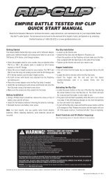
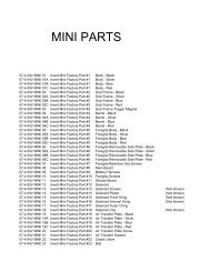
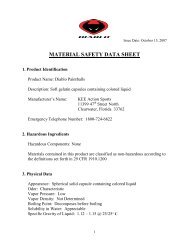
Adjusting VelocityAt the back of the Empire AXE main body is the bolt guide cap. The Allen screw in thebolt guide cap serves as your velocity adjuster. Confirm that the pressure on your EmpireAXE bottom-line regulator is at 180–200 psi. Then you can increase or decreasethe velocity on your Empire AXE by tightening or loosening the velocity adjustmentscrew, with a 1/4” inch Allen wrench; see Fig. 10.2.• To increase (+) velocity, unscrew or loosen the velocity adjustment screw byturning it counter-clockwise. Rotate the velocity adjustment screw counterclockwisein small increments (1/4 turn or less), stopping between slight turns totest velocity, until desired velocity is achieved. Do not back the adjuster out passedbeing flush. Stop if you hear an air leak, and adjust back in a 1/4 turn. A paintballspecific radar chronograph should be used to accurately measure your velocity.• To decrease (-) velocity, tighten or screw-in the velocity adjustment screw byturning it clockwise. Rotate the velocity adjustment screw clockwise in smallincrements (1/4 turn or less), stopping between slight turns to test velocity, untildesired velocity is achieved. A paintball-specific radar chronograph should beused to accurately measure your markers velocity.11. ProgrammingWarning: Before adjusting functions, remove the air source from the Empire AXE andinstall barrel-blocking device.The board inside your Empire AXE features 5 functions and uses a 3-color LED indicatoron the backside of the front fore-grip to indicate functions and modes duringprogramming.To adjust the board settings, place the Empire AXE on a flat surface with barrel pointingto the left. Using a 5/64” Allen wrench, loosen the screw that secures the removablefore grip door, remove the door, and set aside. This will expose the battery andthe circuit board.Locate the two buttons which are used to adjust the settings. The function button (B)is a small black button on the rear of the board, to the left and slightly above the powerbutton (A); see Fig.11.1 It is not necessary to remove the board from the housing inorder to manage settings.B.(Fig. 10.2)A.(Fig. 11.1)Notes:• This marker was designed with safety and safety standards in mind. If you attemptto shoot paintballs at a higher velocity than established safety standards, themarker may not function properly.• Check the velocity every time before using your Empire AXE.Functions and ModesThe Empire AXE must be off to begin managing functions. While the Empire AXE isoff, press the function button (B) to access one of the 5 different functions and makeadjustments.
Once you push the function button the appropriate amount of times to get into the desiredfunction, the LED will flash a specific color per the descriptions below followedby a number of flashes which will indicate the current setting in that function.• Firing Modes (Solid Red LED)• Rate of Fire (Solid Green LED)• Dwell (Solid Orange LED)• BIP Delay (Flashing Red LED)• Ramping Point (Quick-Flashing Green LED)To increase or decrease a setting of a function, use the power button (A) and functionbutton (B). The power button (A) will decrease a setting by one every time it is pushed.The function button (B) will increase a setting by one every time it is pushed. Thesetting can be changed when the function you select has a solid light LED which willcome on before the board flashes the current setting.Example: Press the function button (B) one time and you will be in function 1 which isfiring modes (solid red), or press the function button 3 times and you will be in function3 which is dwell (solid orange).Firing ModesTo get into the firing mode function, make sure the power is off; then push the functionbutton one time and the LED will turn to red and then flash to indicate the firingmode that it is currently in. For example the default mode is Semi-Auto which will bedemonstrated by 1 flash. There are 4 firing modes:• Semi-Auto (1 Flash) — One shot per trigger pull, defaulted to 20 bps maximum.• Ramping/PSP (2 Flashes) — The Empire AXE will operate in semi-auto mode forthe first 3 shots; then if player achieves the maximum trigger pull as defined by theramping point value in function 5, which is defaulted to 4 trigger pulls per second forthis mode, the Empire AXE will ramp to the rate of fire value in function 2, which isdefaulted to 13 shots per second for this mode.• Full-Auto/NXL (3 Flashes) — The Empire AXE will operate in semi-auto mode forthe first 3 shots; then pull and hold trigger on the 4th shot, and the Empire AXE will firefull-auto at the rate of fire value in function 2, which is defaulted to 13 shots per secondfor this mode.• Ramping/Millen. (4 Flashes) — The Empire AXE will operate in a semi-auto modeuntil player achieves the maximum trigger pull as defined by the ramping point value infunction 5, which is defaulted to 6 trigger pulls per second for this mode. At that point,and as long as 6 trigger pulls per second are maintained, the Empire AXE will ramp tothe rate of fire value in function 2, which is defaulted to 10 shots per second for thismode.Note: After modes 2 –4 are selected, it is possible to raise or lower both the rate of fireand ramping point values in case the tournament rules change.To cycle through the firing modes you use both the power and function buttons. Onceyou push the function button one time to get into the firing modes the LED will flashred. While the LED is lit red, push the function button (B) to cycle up (from 1 for semiautoto 4 for NXL full auto) and to go the opposite direction (from 4 at NXL full autothrough to 1 for semi-auto). Use the power button (A) to cycle down.Example: If you are in the default semi-auto mode and want to go to full-auto/NXL,push the function button (B) twice while the LED is lit red. Upon release you shouldsee the LED flash red 3 times. To move from full-auto/NXL to ramping/PSP, push thefunction button (B) one time to get into firing modes, then while LED is lit solid red,push power button (A) one time and release. The LED should flash red two times toindicate that you are now in firing mode 2-ramping/PSP.
Max Rate-of-Fire (ROF)To get into the ROF function, make sure power is off, then push function button (B)two times and LED will turn to a solid green and then flash to indicate the currentmaximum rate of fire that you are currently set to. Default is 20 BPS (balls per second).To adjust ROF push the function button (B) two times and while the LED is lit a solidgreen use either the function button (to toggle up or increase your ROF) or the powerbutton (to decrease the ROF). Max rate of fire is adjustable from 8–20 bps, with .5 bpsincrements.Example: To start you will be in a default setting of 20 BPS. Push the function buttontwice to get into ROF mode. While the LED is lit a solid green, press the power button(A) 5 times to take you to 15 BPS. Upon releasing the function button, the LED shouldthen blink 15 times indicating your new rate of fire.ROF (rate of fire)Flash BPS Flash BPS1 8.0 14 14.52 8.5 15 15.03 9.0 16 15.54 9.5 17 16.05 10.0 18 16.56 10.5 19 17.07 11.0 20 17.58 11.5 21 18.09 12.0 22 18.810 12.5 23 19.011 13.0 24 19.512 13.5 25 20.013 14.0Dwell SettingTo get into the dwell function, make sure the power is off, and then push the functionbutton (B) three times and the LED will turn to a solid orange and then flash toindicate the current dwell setting. The Empire AXE dwell setting is defaulted at setting28 (28 x .25 milliseconds = 7 ms). Dwell is adjustable from 1–45. This function is alsocontrolLED through the same techniques used for firing modes and ROF functions,while the LED is lit a solid orange, increase or decrease your dwell by increments of.25 milliseconds.BIP (Ball in Place) DelayTo get into the BIP function, make sure the power is off, and then push the functionbutton (B) 4 times. The LED will quickly flash red to indicate that you are in the BIPfunction. Then the LED will slowly flash to indicate the BIP setting that you are currentlyusing.Default is (5) (one flash =1 millisecond). BIP is adjustable from 1–40 milliseconds. Thisfunction is also controlLED through the same techniques used for firing modes andROF functions. While the LED is red, increase or decrease your BIP in 1 millisecondincrements.Note: If you are not using a force-feed loader, it is recommended that you use a higherBIP setting.
Ramping PointTo get into the ramping point function make sure the power is off, then push the functionbutton 5 times and the LED will turn to a quickly flashing green and then slowlyflash to indicate the ramping point setting you are currently using. The default rampingpoint for PSP firing mode is 8 flashes (4 BPS). The default ramping point when firingmode is changed to millennium firing mode is 10 (5 BPS). Ramping point is adjustablefrom (3– 9 BPS). Please see chart for corresponding flashes/pulls to ramp settings.Ramping PointFlash BPS6 3.07 3.58 4.09 4.510 5.011 5.512 6.013 6.514 7.015 7.516 8.017 8.518 9.0Factory <strong>Board</strong> ResetThere are three ways to reset the circuit board to default factory settings.• Turn the power off then push the function button and power button at thesame time.• Remove the battery then simultaneously push and hold the function button andpower button for a full 10 seconds.• Disconnect the battery and leave it idle for 15 seconds.<strong>Board</strong> Defaults1. Firing Modes – 1 blink (Semi-auto)2. Rate of Fire – 25 blinks (20 BPS)3. Dwell - 28 blinks (7 ms)4. BIP Delay – 5 blinks (5 ms)5. Ramping Point – 8 (4 BPS) for PSP, 10 (5 BPS) for Millen.12. Trigger AdjustmentsThe Empire AXE trigger can be adjusted by the four set screws in the trigger. Three ofthe set screws can be adjusted without removing the trigger frame assembly.When a trigger pull is recognized, the LED will quickly flash a dim red for each triggerpull. If no trigger pull is recognized, the LED flashes normally based on the status ofthe eyes and battery power level. If the trigger is held in, the dim red LED will stayilluminated.Before making any trigger adjustments, de-gas the Empire AXE, make sure the gaugereads 0 psi, and then switch on the Empire AXE with eyes turned off to easily monitorthe current activation point by watching the LED, while listening to the solenoidclicking.You will notice three set screws in your trigger (Fig. 12.1). These can be adjusted witha 1/16” Allen wrench. Make small adjustments and check that the trigger is activatingthe solenoid.
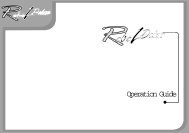
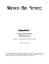
12. Trigger Adjustments.....(continued).13. General MaintenanceCAUTION: Before attempting to perform any maintenance operations, make surethat all paintballs and air sources have been removed from the marker and that theregulator gauge reads 0 psi. Install a barrel-blocking device, and push the powerbutton and hold for over 2 seconds until the LED light changes from red to green. Keepthe Empire AXE power off.Keep your Empire AXE clean and lubricated to eliminate the friction that would preventreliable operation. It is recommended that you clean and lube the marker before eachuse.123(Fig.12.1)• The (1) first set screw located in the top of the trigger adjusts forward movement,and forward stop point.• The (2) second set screw adjusts the rear movement range, and rear stop point.• The (3) third set screw located at the bottom of the trigger adjusts the triggermagnetic return. Turn it clockwise to increase the return strength and counterclockwise to decrease the return strength.• The first screw adjusts the trigger activation point. This screw can only be adjustedonce the frame or trigger has been removed. It is recommended that you do notadjust the factory setting of this set screw as setting this set screw to high maycause damage to the trigger switch.Notes:• Normal activity may cause set screws to back out of adjustment. If necessary useblue loctite to help keep them set correctly. However do not use an excessiveamount and allow the blue loctite to dry overnight before using your Empire AXE.• If any of the set screws are over adjusted in any direction the Empire AXE may notfi r e .• If the trigger travel is adjusted too short, the Empire AXE may fire on its own,repeatedly and/or uncontrollably.Do not use oil or petroleum-based lubricants in the lubrication of this marker. Teflonor silicon (non-spray only) lubricants designed for use on O-rings may be used forlubrication for the bolt, bolt guide and poppet area only. Dow 33 or the include factorygrease is recommended.External CleaningUse a clean cloth, dampened with water to clean the outside of the Empire AXE. Donot use any chemicals, as you may damage the protective finish.Warning: Do not rinse the Empire AXE under water, as you may damage the marker’selectronics.Internal Cleaning and GreasingThe Empire AXE is designed for easy access to the bolt guide assembly without removingany hardware. On the back of the Empire AXE is a push button to allow suchaccess for cleaning and maintenance. Refer to Section 15 for instructions on boltguide removal.
14. Storage and TransportationCaution: Never carry your Empire AXE uncased when not on a playing field. The nonplayingpublic and law enforcement personnel may not be able to distinguish betweena paintball marker and firearm. For your own safety and to protect the image of thesport, always carry your Empire AXE in a suitable marker case or in the box in whichit was shipped.• Your Empire AXE must be clear of all paint and propellant when not being usedduring transportation.• Make sure the Empire AXE marker is off. Push the power button and hold for2 seconds until the LED light changes from red to green.• Put the barrel-blocking device in its place.• Make sure the marker is clean.• Store your Empire AXE in a clean, cool, dry place.• Keep your Empire AXE away from unauthorized and unsafe users.• It may be a good idea to remove the battery when storing your Empire AXEto prevent unauthorized use.• Protect your Empire AXE from excessive heat during transportation.Observe and obey all local, state, and federal laws concerning the transportation ofpaintball markers. For information concerning any of the laws in your area, contactyour nearby law enforcement agency.If you must ship your Empire AXE for any reason, the box in which you purchased themarker should be used to protect your marker against rough handling during transport.Never ship charged CO2 or pressurized gas cylinders!15. Assembly/DisassemblyCAUTION: Before attempting to perform any marker disassembly, make sure that allpaintballs and air sources have been removed from the marker and that the regulatorgauge reads 0 psi. Install a barrel-blocking device. Push the power button and holdfor over 2 seconds until the LED light changes from red to green. Keep the EmpireAXE power off.Disassembly Tips• Make sure you have a clean area to work on your marker, so you don’t lose ormisplace parts.• Make sure the main spring is installed correctly on the bolt, as it needs to beinstalled in the right direction.• After reassembling the Empire AXE recheck your trigger activation settings.• Visit <strong>Paintball</strong><strong>Solutions</strong>.com for additional information.BarrelIt is recommended that the barrel be removed before any maintenance or disassemblyis performed. Simply turn the barrel counter-clockwise to remove. Use warm waterand a barrel cleaning device to keep the barrel in top condition.Bolt Guide AssemblyRemoval of Bolt and Bolt Guide AssemblyBefore you remove the bolt guide assembly, make sure you remove your air cylinderand that the pressure gauge reads 0 psi.• Push and hold in the bolt guide release button at the rear of the marker while therear of the marker is facing a safe direction.• While holding the button in, turn the bolt guide clockwise until it stops.• The bolt guide assembly should spring back and stop; if it does not, pull it backuntil it stops.• Next, push the bolt guide assembly slightly forward and then turn it counterclockwiseand remove.• If the bolt and spring do not come out with the bolt guide, use a barrel swab topush them out from the front of the marker.
Maintenance of Bolt and Bolt Guide• Inspect the O-rings on both the bolt and bolt guide for any wear or damage.Replace damaged or worn O-rings if necessary.• Wipe the parts down with a clean rag removing any old grease or debris.• Lubricate all O-rings on bolt and bolt guide with the supplied grease or Dow 33.Only a small amount of grease is needed.Maintenance of PoppetWhile the bolt guide assembly is out of the marker, you can service the poppet. Keepingthe poppet oring greased will make your AXE operate properly.• Use a 1/4” Allen wrench and insert it into the back of the bolt guide cap. Turncounter-clockwise until bolt guide cap is completely removed.• Inspect and lubricate bolt guide cap O-ring with grease.• Using the 1/4” Allen wrench, carefully insert it into the front of the bolt guide,pushing the poppet assembly (poppet and poppet spring) out the back of thebolt guide.• Inspect and lubricate poppet O-ring with grease and be careful not to lubricate thefront poppet seal. Your poppet seal should always stay dry.Reinstallation of Poppet, Poppet Spring and Bolt Guide Cap• Place poppet assembly into the back of the bolt guide and gently push forward.If installed properly, the poppet assembly will be all the way forward resting onthe bolt guide internal face.• Make sure the poppet spring is seated straight in the back of the poppet• Using the 1/4” Allen wrench, screw the bolt guide cap clockwise back into thebolt guide.• Screw the bolt guide cap all the way in, then turn out 3/4 of a turn.• Further adjustment over a chronograph will be needed to achieve desired velocity.Reinstallation of Main Spring, Bolt, and Bolt Guide AssemblyBefore reinstalling the bolt guide assembly, make sure the inside of the body is cleanand that the main spring is properly installed on the bolt. The main spring should lockonto the back of the bolt; if it’s on incorrectly it will be lose and will affect the AXE’sperformance.• Slide the bolt guide assembly into the body, aligning the bolt guide alignmentpin with the slot in the bolt guide release housing.• Push the bolt guide forward, then clockwise and forward again, until it’s flushwith the body.• Next, push the bolt guide assembly release button and turn the bolt guidecounter-clockwise• Release the locking button and confirm that the bolt guide is now locked in place.It should not be able to turn or move forward or back if installed correctly.Fore GripRemoval of Fore Grip Assembly• Using a 1/16” Allen wrench, loosen the fore grip retention set screws. They do notneed to be fully removed, only loosened.• The fore grip assembly will now slide down the front rail on the grip frame.Installation of Fore GripTo reinstall the fore grip assembly on to the marker, slide the fore grip assembly backonto the rail on the front of the grip frame. Slide fore grip assembly all the way upuntil it is back in place. Using the 1/16” Allen wrench, tighten the foregrip retentionset screws. Do not over tighten the set screws as they can become damaged easily.Note: If not installed correctly, you might damage the circuit boards!
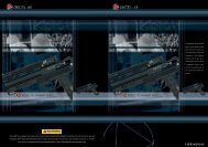
Grip Frame and Bolt Guide Locking AssemblyWarning: It is recommended that you do not remove the grip frame, as removing itwill expose the bolt guide locking assembly; this consists of a spring, detent, and button.These parts are held in place by the grip frame. If you do need to remove the gripframe, be careful not to lose these parts.Removal of Grip Frame• Using a 1/8” Allen wrench, remove both grip frame retention screws turningby them counter-clockwise.• Gently pull the frame up from the body. When pulling the frame off the body,make sure not to lose the bolt guide locking components.Bolt Guide Locking Assembly• Before you re-installing the grip frame make sure the bolt guide locking detent iswithin the housing; see Fig. 15.1.• Applying grease to the bolt guide locking detent will help keep it in place.(Fig. 15.1)• Next check that the bolt guide locking button and spring are located correctlywithin the grip frame; see Fig. 15.2.(Fig. 15.2)• Once you have confirmed all of the bolt guide locking parts are in place, youcan install the grip frame.Installation of Grip Frame• Inspect the male air transfer tube bottom O-ring and lightly grease.• Make sure the bolt guide locking spring and button are in place within the frameand that the bolt guide locking detent is within the air transfer plate.• As you install the grip frame, make sure the solenoid wires do not get pinched.• Gently push grip frame back on and line up the air transfer tubes.• When frame is back on, use the 1/8” Allen wrench and tighten the (2) grip frameretention screws clockwise.Removal, Installation, and Cleaning of Ball Detents• Using a 5/64” Allen wrench, insert Allen wrench into detent cover and turncounter-clockwise.• Clean the detents with a damp cloth and apply a small amount of grease tothe outer sides of the detents if sticking is an issue.• Installation is the reverse of the removal. Do not over tighten the ball detent covers!Note: Be careful not to lose any of the detent parts as they are small.
RegulatorRemoval of Regulator• Loosen the two regulator mount set screws located on the bottom of the grip framewith a 3/32” Allen wrench by turning them counter-clockwise.• The regulator and regulator mount can now be pulled down and removed fromthe grip frame. Be careful not to lose the female air transfer tube bottom O-ring,which sits on the bottom of the female air transfer tube.Installation of Air Transfer Plate• It is recommended that a small amount of factory-supplied grease orDow 33 grease is applied to the air transfer gasket before the air transfer plateis reattached.• Also make sure the check valve is in the body; see Fig. 15.3.• Place transfer plate back on body and evenly tighten all seven screws.• Plug the solenoid back into the sensor board.Installation of Regulator Assembly• Make sure the female air transfer tube O-ring is on the bottom of the air tube;grease if necessary.• Slide regulator and regulator rail back into the grip frame and tighten the regulatormount set screws with a 3/32” Allen wrench.Note: There are also two set screws in the regulator rail; they should only need to beadjusted if the regulator becomes loose.Warning: Do not take the regulator apart; it is not designed to be user serviceable.Damage to the regulator will not be covered under warranty.Air Transfer PlateRemoval of Air Transfer Plate• Remove fore grip and grip frame.• Carefully unplug the solenoid from the sensor board.• Remove the solenoid and male air transfer tube from the air transfer plate byunscrewing them counter-clockwise.• Using a 5/64” Allen wrench, remove all of the air transfer plate screws (6 total).Once the screws are removed the air transfer plate will then lift off.Note: Be careful not to lose the check valve (air restrictor). The check valve is a smallplastic piece located between the body and air transfer plate. Using grease on thecheck valve will help hold it within the body.(Fig. 15.3)Sensor <strong>Board</strong>Removal and Cleaning of Sensor <strong>Board</strong>• Remove fore grip, grip frame, and air transfer plate as described in thesteps above.• Gently remove the sensor board from the body.• Once board is removed, use a dry cloth to clean sensors, if paint is on the board,use a dry cloth to wipe paint off the board.Installation of Sensor <strong>Board</strong>• When installing sensor board back in main body, be careful that the sensors lineupcorrectly. The board should drop into the body very easily. Do not force the sensorboard into the body.
16. Troubleshooting GuideNote: If you are experiencing any problems and you are using any aftermarket parts, it is necessary to re-install the factory parts and re-test beforeattempting any troubleshooting, as non-factory aftermarket parts are not designed by Invert <strong>Paintball</strong> to work in the AXE, and they may be thecause of the problems. Do not contact Invert <strong>Paintball</strong> until you have returned the AXE to factory stock condition and tested.Does not turn on Make sure you have a fresh battery. If you have tried several different batteries, check to make sure the battery harness is plugged in to the board properly. Ifit is, unplug the battery from the harness for 5 minutes, then plug back in and try again.Doesn't fireMake sure the marker is turned on.Check the LED light on the back of the foregrip. The LED should be rapidly blinking green when a paintball is present.Doesn't fire with eyes turnedoffMake sure you have a paintball in thechamber.Trigger may need to be adjusted.Trigger may need to be adjusted.Solenoid may not be connected properly.The anti-chop eye system prevents the marker from firing unless a ball is present. Never put anything other than apaintball down the feedneck of the AXE.Check the LED light on the back of the foregrip. While holding in the trigger, the LED should stay red in the background,and not be red when the trigger is released. If it is not that way, then the trigger may need to be adjusted. See the"Adjusting your trigger" section earlier in the manual.Check the LED light on the back of the foregrip. While holding in the trigger, the LED should stay red in the background,and not be red when the trigger is released. If it is not that way, then the trigger may need to be adjusted. See the "Triggersdjustments" section earlier in the manual.Check to make sure the solenoid is connected properly to the sensor board. If it is, the solenoid may need to be reset.Leaks constantly throughthe chamberSolenoid may need to be reset.Poppet may need to be reset.To reset the solenoid, with the eyes off, pull the trigger repeatedly until the solenoid makes a loud clicking sound againwith each trigger pull, but do not pull the trigger more than 10 times, as this can damage the solenoid. If after 10 pullsthe solenoid still doesn't click, it may need to be serviced.To reset the poppet, remove the gas source from your AXE. Gently turn the velocity adjuster all the way in until it stops.Then gas up your AXE. If the leak has stopped, proceed to back out the velocity adjuster 3/4 of a turn, then measurevelocity with a chronograph and adjust as needed. If a small leak continues upon backing out the velocity adjuster, the airpassage through the poppet may be blocked, or the poppet seal face may be worn and needs to be replaced.Air coming out of body infront of triggerSolenoid may need to be reset.To reset the solenoid, with the eyes off, pull the trigger repeatedly until the solenoid makes a clicking sound again witheach trigger pull, but do not pull the trigger more than 10 times, as this can damage the solenoid. If after 10 pulls thesolenoid still doesn't click, it may need to be replaced.During each shot, it is normal for a puff of air to exit the body just in front of the trigger.Multiple balls fired from onlyone shotLoader forcing paintballs too hard into marker.Detents StickingIf the marker fires one time, but more than one ball exits the barrel, your loader may be pushing the paintballs into themarker too hard, and they are going past the ball detents. Remove both ball detent covers and clean the ball detents witha cloth. You may also add some grease to the outer surface of the detents to make sure they are not sticking within thecovers.Remove both ball detent assemblies and clean the ball detents with a cloth. You may also add some grease to the outersurface of the detent to make sure they are not sticking within the detent cover.
16. Trouble Shooting Guide.....(continued)Shoots more than once fromone trigger pullBattery may be low. Replace battery with a fresh Duracell or Energizer brand alkaline 9V.Trigger may need to be adjusted.Make sure the trigger has plenty of travel both before and after the activation point.Regulator leaks from bottomplugAdjust over-pressurization relief valve.The plug on the underside of the regulator is an over-pressurization relief. If it is leaking, most likely the regulator is setto too high of a pressure and needs to be lowered. If the regulator is set to 200 psi or less and the over-pressurizationrelief is still leaking, it is possible to turn the plug cap just a small amount in the clockwise direction, until the leak stops.Regulator is slow to rechargeAir tank is not screwed all the way into the<strong>Axe</strong>'s regulator ASA.If during rapid firing the first ball comes out of the barrel at full velocity and following shots decrease substantially, watchthe gauge on the AXE regulator to see if the needle drops down significantly and is slow to come back to the set pressure.This is typically the result of not screwing your air tank in enough. When screwing your air tank into the AXE's regulatorASA, it is important to not stop as soon as the marker pressurizes, but to continue turning until the air tank stops. It isalso acceptable to install the air tank when it is empty, then have it filled by a professional while it is installed. This willensure that you get the maximum air flow from your air tank.Regulator pressure spikesBreaks paint in chamberRegulator adjusted too high.Eyes are turned off.Low quality or brittle paintballs.If the needle on the regulator's gauge climbs well over 200 psi when attempting to install the air tank, first remove thebrass adjustment screw in the front of the regulator and try again to install the air tank. If the needle reads 0, reinstallthe adjustment screw and turn in until the needle reads 200 psi.Only fire paintballs with the eyes on.Do a paintball drop test. On a level and smooth, hard, outdoor surface, such as concrete or asphalt pavement, drop tenpaintballs one at a time from about 5 feet high. Don't toss them up or throw them at the ground, just drop them straightdown. If more than 3 paintballs out of 10 break, the paintballs are bad and should not be used in the AXE. In the case ofhigher-end tournament-grade paintballs, it may be possible to tune the AXE to successfully fire brittle paintballs. Sinceall conditions are different, it is best to ask for help with this from your local pro shop.Cycles very slowLoader pushing too hard.Bolt or bolt guide o-rings may be worn.Bolt front seal may be missing.Check valve may be missing.Ball detents may be dirty or worn.Regulator pressure may be set too high.Bolt or bolt guide o-rings may need grease.Try a different loader, such as the Empire Magna Drive Loader. If using a Halo series or Empire Reloader B series loader,try installing an Empire Magna Clutch Upgrade Kit.Air blowing past worn o-rings can easily break paintballs in the feed neck. Replace the bolt O-rings and the smaller 3 boltguide guide o-rings and apply fresh grease.Make sure the bolt front seal is in place and has a light application of grease to reduce friction.Make sure the check valve is in place. Without the check valve, the forward force on the bolt is too great and can be toohard on the paintballs.Clean the ball detents. If necessary, apply a small amount of grease around the outer surface to reduce friction inside theball detent covers. Replace if tips are worn down.Lower regulator pressure.Clean off old grease from the bolt and bolt guide O-rings, as well as the bolt front seal, and apply fresh grease.Rate of Fire setting may be adjusted too low.Raise Rate of Fire setting.Loader may not be feeding fast.Check your loader's batteries or use a faster loader.
Inconsistent velocityPressure may be set too low.Marker may need to be greased.Dwell may be set too low or too high.Check valve may be missing.Low pressures have difficulty supplying enough volume to maintain a constant velocity. Do not lower your AXE's regulatorpressure below 180 psi.Clean old grease from the poppet, bolt, and bolt guide O-rings and apply fresh grease. Do not use too much, as it willprevent the moving parts from cycling smoothly.Reset the dwell setting to the factory default.Make sure the check valve is in place.Battery may be low. Replace battery with a fresh brand-name alkaline 9V.Velocity drops off whenfiring multiple shotsPoppet o-ring may be worn.Air tank is not screwed all the way into theAXE's regulator ASA.Replace poppet o-ring and apply fresh grease.If during rapid firing the first ball comes out of the barrel at full velocity and following shots decrease substantially, watchthe gauge on the AXE regulator to see if the needle drops down significantly and is slow to come back to the set pressure.This is typically the result of not screwing your air tank in enough.Scratches on bolt Spring may be damaged. This can cause negative performance. The main spring should be repaired by a trained technician or it can just bereplaced.Leaks sometimes whileshooting multiple shotsPoppet may be sticking open.Clean the old grease from the poppet O-ring and apply fresh grease. If that doesn't help, replace the poppet O-ring andapply fresh grease.Battery may be low. Replace battery with a fresh brand-name alkaline 9V.Solenoid may be sticking open.If the solenoid is sticking open occasionally, the regulator pressure may be set too high. If the pressure is set to 200 psi orless, then the solenoid may be filled with dirt and/or grease. Do not attempt to disassemble the solenoid. Only a trainedtechnician should do this. Attempting to disassemble the solenoid will void the warranty. Take it to a trained technicianfor service or contact <strong>Paintball</strong> <strong>Solutions</strong>.Regulator's on/off lever ishard to operateParts are dryIf the on/off lever becomes hard to operate, you can add afew drops of oil on the base of the lever and work it back andforth. Only a small amount of oil is needed.
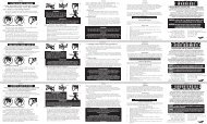
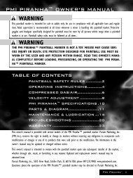
17. Diagrams and Parts ListREF # DESCRIPTION SKU #1 Set Screw (6-32 x .250) 175232 Main <strong>Board</strong> 175243 Battery Harness 175254 <strong>Board</strong> Screw 175265 Solenoid 175286 Air Transfer Plate Screw 175297 Air Transfer Gasket 175308 Check Valve 175319 Bolt 1753210 Bolt Rubber Tip 1753311 Bolt Oring 1753412 Main Spring 1753513 Bolt Guide Small (Front) Oring 1753714 Bolt Guide Cap Oring 1753815 Poppet with Spring 1753916 Poppet Oring 1754017 Feedneck Collar 1754518 Feedneck Screw 1754919 Air Transfer Tube Male 1755120 Air Transfer Tube Male Top Oring 1755221 Air Transfer Tube Male Bottom Oring 1755322 Air Transfer Tube Female 1755423 Air Transfer Tube Female Oring 1755524 Regulator Mount 1755625 Set Screw (10-24 x .250) 1755726 Regulator Cap Set Screw 1759927 Trigger Set Screw W/ Magnetic Top (chrome top) 1756428 Primary Body Retention Screw 1756529 Screw (BH 6-32 x .250) 1756730 Regulator Adjustment Screw 1759031 Poppet Spring 1762332 Poppet Seal 1762933 Body - Dust Black 7230034 Barrel - Dust Black 7230435 Grip Frame - Dust Black 7230836 Foregrip Body - Dust Black 7231237 Foregrip Door - Dust Black 7231638 Air Transfer Plate - Dust Black 7231939 Feedneck- Dust Black 7232340 Feedneck Clamp - Dust Black 7232741 Sensor <strong>Board</strong> 7233142 Bolt Guide - Black Dust 7233243 Bolt Guide Cap 7233644 Bolt Guide Large O-ring 7234045 Bolt Guide Lock Kit (3pc- spring, detent, button) 7234146 Bolt Guide Release Housing 7234547 Regulator - Dust Black (Complete) 7235048 Black 300psi Empire gauge 7237549 Trigger - Dust Black 7237750 Trigger Bearing 7238151 Trigger Pin (.155'") 7239452 Black/White Grips 7238253 Detent Assembly- (3pc) Dust Black 72386
17. Diagrams and Parts List ....(continued)103439 40 17918425333123233724163638412152087464511134416311415435019352950511492728122252829 2924233047522648
Empire <strong>Paintball</strong>570 Mantua Blvd.Sewell, NJ 08080www.empirepaintball.comEmpire <strong>Paintball</strong> is a brand of KEE Action Sports, Llc.Covered by one or more of the following U.S. patents: 5,881,707; 5,967,133; 6,035,843; 6,474,326; 6,637,421 and 7,100,593, marked under license; 6,601,780, 6,925,997, 6,161,573, 6,057,750and EPC Patented.
LIMITED LIFETIME WARRANTY INFORMATION (ORIGINAL PURCHASE RECEIPT REQUIRED)KEE Action Sports (“KEE”) warrants that this product is free from defects in materials and workmanship for as long as it is owned by the original purchaser, subject to the termsand conditions set forth below. KEE Action Sports will repair or replace with the same or equivalent model, without charge, any of its products that have failed in normal usebecause of a defect in material or workmanship.KEE Action Sports is dedicated to providing you with products of the highest quality and the industry’s best product support available for satisfactory play.Purchaser should register product to activate warranty. Register your product by:1. Online at www.paintballsolutions.com2. Complete the product registration card (if applicable) and mail along with a copy of your receipt to <strong>Paintball</strong> <strong>Solutions</strong>, 11723 Lime Kiln Rd., Neosho, MO 64850.WHAT THIS WARRANTY DOES NOT COVERThis warranty does not cover problems resulting from abuse, the unauthorized modification or alteration of our product, problems resulting from the addition of aftermarketproducts and scratches or minor superficial imperfections. Due to the nature of paintball products it is important that the product be maintained by the user as indicated in theproduct manual to remain in good operating condition. Your Limited Lifetime Warranty will be void if you fail to maintain the product as recommended in the product instructionmanual. In addition, certain parts of a product may be subject to wear through regular usage. Replacement and repair of such parts is the responsibility of the user throughoutthe life of the product. These parts are not covered under the Limited Warranty. Examples of this type of part include (but are not limited to) goggle lens, straps, O-ring seals,cup seals, springs, ball détentes, batteries, hoses, drive belts, gears and any part of a product subject to continuous impact from paintballs. Hydrotesting of air cylinders is notcovered under this warranty.The Limited Lifetime Warranty also does not cover incidental or consequential damages. This warranty is the sole written warranty on KEE’s product and limits any impliedwarranty to the period that the product is owned by the original purchaser.Some states, provinces and nations do not allow the limitation of implied warranties or of incidental or consequential damages, so the above limitations or exclusions may notapply to you. This warranty gives you specific legal rights and you may also have other rights which vary from state to state, province to province, nation to nation.If you should encounter any problems with your product and you have added aftermarket parts on your product, please test it with the original stock parts before sending it in.Always unload and remove air supply before shipping markers. Do not ship your air supply tank if it is not completely empty. Shipping a pressurized air supply tank is unsafeand unlawful. Remove all batteries from products prior to shipping.This Limited Warranty gives you specific legal rights, and you may also have other rights which vary from state to state. Some states do not allow the exclusion of incidental or consequential damages.For Warranty parts, service, information or manualsin other languages, (where applicable) go to:<strong>Paintball</strong> <strong>Solutions</strong>: www.paintballsolutions.comE-Mail: tech@paintballsolutions.comTelephone: 1-800-220-322211723 Lime Kiln Rd., Neosho, MO 64850