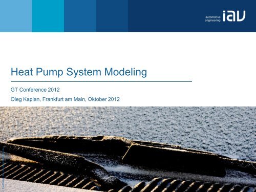
Heat Pump System Modeling
Heat Pump System Modeling
Heat Pump System Modeling

You also want an ePaper? Increase the reach of your titles
YUMPU automatically turns print PDFs into web optimized ePapers that Google loves.
Power [kW] / Waste heat flow [kW]MotivationRequired wasteheat fowInsufficient waste heat flow toaccomplish the customer’s demandfor comfort especially for HEVs andBEVsTemperature level of coolant too lowto fulfill the customer’s demand forcomfortHigh demand for additional heatsources especially for BEVsICE Internal Combustion EngineHEV Hybrid Electric VehicleBEV Battery Electric Vehicle© IAV · 10/2012 · oka · VI-E22 2
Power [kW]Impact of Conventional Auxiliary <strong>Heat</strong>ers• Electric heaters significantly decrease thepure electric driving range• Strong conflict between acceptabledriving range and high comfort level• Fuel heaters do not fulfill zero emissionrequirement.• Refueling an additional fuel decreasesthe driver’s comfortNew system approaches must beinvestigated to fulfill the customer’sdemand© IAV · 10/2012 · oka · VI-E22 3
Pressure [bar]Motivation for <strong>Heat</strong> <strong>Pump</strong> Investigationsaturated vaporsaturated liquidSpec. heaterpower.Q• Use of the environment as a heatsource at low temperature levels• Use of further waste heat producerslike EM, PE, as a heat sourceThe use of a heat pump makes aCOP of 3 or higher possible<strong>Heat</strong> pump system is superior toconventional electric heaters..QSpec.compressorpowerEnthalpy [kJ/kg]P fluidEM Electric MotorPE Power ElectronicCOP Coefficient Of Performance© IAV · 10/2012 · oka · VI-E22 4
RadiatorHCHVHConcept for a New <strong>Heat</strong> <strong>Pump</strong> DesignPEEMBPHE 1 BPHE 2P 2PECUPower electronicsCharging unitP 1CUDCD/CEMDC/DC-converterElectric motorTHCV 1CV 2HC<strong>Heat</strong>er coreEXV 1EXV 2HVCHigh voltage heaterElectrically driven pumpSOV 4ReceiverSOV 3Electric expansion valveCheck valveElectrically drivenrefrigerant compressorSOV 1EDRCSOV 2Brazed plateheat exchangerShut-off valveThermostat© IAV · 10/2012 · oka · VI-E22 5
RadiatorHCHVHConcept for a New <strong>Heat</strong> <strong>Pump</strong> Design<strong>Heat</strong>ing ModePEEMBPHE 1 BPHE 2P 2PECUPower electronicsCharging unitP 1CUDCD/CEMDC/DC-converterElectric motorTHCV 1CV 2HC<strong>Heat</strong>er coreEXV 1EXV 2HVCHigh voltage heaterElectrically driven pumpSOV 4ReceiverSOV 3Electric expansion valveCheck valveElectrically drivenrefrigerant compressorSOV 1EDRCSOV 2Brazed plateheat exchangerThermostatHigh temperature coolant loopShut-off valveLow temperature coolant loopclosedRefrigerant loop© IAV · 10/2012 · oka · VI-E22 6
From Concept to ModelCore components of the heat pump system to be modeled• Refrigerant compressor mechanically driven with and without displacement orelectrically driven• Brazed plate heat exchanger. One used as an evaporator and one as a condenser• Expansion valve thermostatic and electrically drivenFurther components• Water pumps• <strong>Heat</strong> exchangers such as Radiator and <strong>Heat</strong>er core• Auxiliary heatersBoundary conditions• Airflow through the heater core heat• Ambient temperature• Driving cycle waste heat from power train© IAV · 10/2012 · oka · VI-E22 7
Compressor power [kW]Refrigerant CompressorSimulation vs. Testpi = 2.6 testpi = 4.3 testpi = 7.8 testpi = 2.6 simulationpi = 4.3 simulationpi = 7.8 simulationn [RPM]pi [-]T in [°C]p in [bar].T out [°C]m [kg/h]P [kW]• Mean deviation in power calculation:0.1 kW• Mean deviation in discharge temperaturecalculation: 2 K• Mean deviation in mass flow calculation:6 kg/hAccurate results at all relevant operationpointsCompressor speed [rpm]Accurate results for the modeledrefrigerant compressors© IAV · 10/2012 · oka · VI-E22 9
BPHE as a CondenserInput from Test BenchInput variables water• Inlet temperature• Inlet pressure• Inlet volume flowInput variables refrigerant• Inlet temperature• Inlet pressure• Mass flowOutput variables water• Outlet temperature• Outlet pressure• <strong>Heat</strong> flowBPHEOutput variablesrefrigerant• Outlet temperature• Outlet pressure• <strong>Heat</strong> flowAdditional information• Detailed geometry dataBPHE Brazed Plate <strong>Heat</strong> Exchanger© IAV · 10/2012 · oka · VI-E22 10
<strong>Modeling</strong> a BPHE as a CondenserNusselt – Reynolds map for the water sideRefrigerant single – phase flow calculation by Dittus – Boelter correlation forcooling Refrigerant two – phase flow calculation by Shah correlationh: <strong>Heat</strong> transfer coefficientRe: Reynolds numberPr: Prandtl numberRe L : Liquid phase Reynolds numberPr L : Liquid phase Prandtl numberk: Thermal conductivityD: Characteristic lengthP re : Reduced pressureP: Actual pressureP cr : Critical pressurex: Refrigerant qualityNu L : Liquid phase Nusselt number© IAV · 10/2012 · oka · VI-E22 11
Simulation [%]BPHE as a CondenserSimulation vs. Test100<strong>Heat</strong> flow condenser80+ 10 %60- 10 %402020 30 40 50 60 70 80 90 100Test [%]• Mean deviation in power calculation: 0.1 kWAccurate results at all performance map points© IAV · 10/2012 · oka · VI-E22 12
<strong>Modeling</strong> a BPHE as a EvaporatorNusselt – Reynolds map for the water sideRefrigerant single – phase flow calculation by Dittus – Boelter correlation forheating Refrigerant two – phase flow calculation by Klimenko correlationh: <strong>Heat</strong> transfer coefficientRe: Reynolds numberPr: Prandtl numberPr L : Liquid phase Prandtl numberk: Thermal conductivityD: Characteristic lengthρ L : Liquid densityρ V : Vapor densityk l : Liquid thermal conductivityk w : Wall material thermal conductivity© IAV · 10/2012 · oka · VI-E22 14
Simulation [%]BPHE as an EvaporatorSimulation vs. Test10080<strong>Heat</strong> flow evaporator+ 10 %6040- 10 %2000 20 40 60 80 100Test [%]• Mean deviation in power calculation: 0.1 kWAccurate results at all performance map points© IAV · 10/2012 · oka · VI-E22 15
<strong>Heat</strong> <strong>Pump</strong> <strong>System</strong> in GT – Suite© IAV · 10/2012 · oka · VI-E22 16
Subcooling [K]Determination of Refrigerant Charge201510TestSimulationConventional systemBoundary conditions• Ambient temperature: 40 °C• Ambient humidity: 40 %• Air flow heater core: 480 kg/h• Air flow radiator: 1600 kg/h• Compressor speed: 4000 U/min• EXV target SH: 5 K50500 550 600 650 700 750 800 850Refrigerant charge [g]No subcooling track in thesystemNo subcooling plateauThe optimal refrigerantcharge is at the kink at 700 gSC SubcoolingSH Superheat© IAV · 10/2012 · oka · VI-E22 17
Power [kW]Validation of the <strong>Heat</strong> <strong>Pump</strong> ModelCompressor Power2.22.01.81.61.41.21.00.80.60.40.20.0With 0.7 kW wasteheat flowTestTestWithout wasteheat flowSimulationSimulation@ -10 °C2000 U/min@ 0°C5000 U/min@ 5°C5000 U/minOperating pointBoundary conditions• Air flow heater core: 300 kg/h• Air flow radiator: 1600 kg/h• EXV target SH: 5 K• Mean deviation in powercalculation: < 0.2 kWAccurate results at all testpoints© IAV · 10/2012 · oka · VI-E22 18
<strong>Heat</strong> flow [kW]Validation of the <strong>Heat</strong> <strong>Pump</strong> Model<strong>Heat</strong>er Core <strong>Heat</strong> Flow3.63.43.23.02.82.62.42.22.01.81.61.41.21.00.8With 0.7 kWwaste heatflowTestTestWithout wasteheat flowSimulationSimulation@ -10 °C2000 U/min@ 0°C5000 U/min@ 5°C5000 U/minOperating pointBoundary conditions• Air flow heater core: 300 kg/h• Air flow radiator: 1600 kg/h• EXV target SH: 5 K• Maximum deviation in heatflow calculation: < 0.4 kW• Mean deviation in heat flowcalculation: < 0.3 kWAccurate results at all testpoints© IAV · 10/2012 · oka · VI-E22 19
<strong>Heat</strong> flow [kW]Validation of the <strong>Heat</strong> <strong>Pump</strong> ModelRadiator <strong>Heat</strong> Flow2.22.01.81.61.41.21.00.80.60.40.20.0Without wasteheat flowTestTestWith 0.7 kW wasteheat flowSimulationSimulation@ -10 °C2000 U/min@ 0°C5000 U/min@ 5°C5000 U/minOperating pointBoundary conditions• Air flow heater core: 300 kg/h• Air flow radiator: 1600 kg/h• EXV target SH: 5 K• Maximum deviation in heatflow calculation: < 0.4 kW• Mean deviation in heat flowcalculation: < 0.3 kWAccurate results at all testpoints© IAV · 10/2012 · oka · VI-E22 20
ConclusionPresented concept• Promising system approach• New components were introduced<strong>Heat</strong> pump modeling and simulation:• <strong>Modeling</strong> of components and of system was achieved• Accurate results both on component and system level• Advantages compared to conventional heater were shown by test data and simulationOutlook• Further know-how development and investigation on transient behavior• Comparison to air / refrigerant heat pumps• Cabin modeling and integration into thermal vehicle simulation© IAV · 10/2012 · oka · VI-E22 21
Thank youOleg KaplanIAV GmbHDomagkstr. 11b, 80807 MünchenTelefon +49 89 23542 6631oleg.kaplan@iav.dewww.iav.com