Aqua 4 Gen Owners Manual.pdf - Fuji Yachts Website
Aqua 4 Gen Owners Manual.pdf - Fuji Yachts Website
Aqua 4 Gen Owners Manual.pdf - Fuji Yachts Website

You also want an ePaper? Increase the reach of your titles
YUMPU automatically turns print PDFs into web optimized ePapers that Google loves.
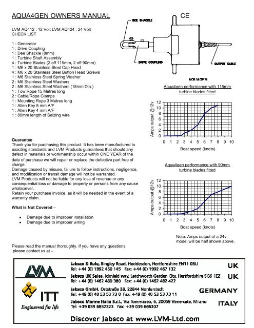
AQUA4GEN OWNERS MANUALCELVM AQ412 : 12 Volt LVM AQ424 : 24 VoltCHECK LIST1 : <strong>Gen</strong>erator1 : Drive Coupling1 : Dee Shackle (8mm)1 : Turbine Shaft Assembly4 : Turbine Blades (2 off 115mm, 2 off 90mm)1 : M6 x 20 Stainless Steel Cap Head4 : M6 x 20 Stainless Steel Button Head Screws1 : M6 Stainless Steel Spring Washer2 : M6 Stainless Steel Washers2 : M6 Stainless Steel Washers (18mm Dia.) <strong>Aqua</strong>4gen performance with 115mm1 : Tow Rope 15 Metres long2 : Cable/Rope Clamps1 : Mounting Rope 3 Metres long1 : Allen Key 5 mm A/F1 : Allen Key 4 mm A/F1 : 80mm length of Seizing wireGuaranteeThank you for purchasing this product. It has been manufactured toexacting standards and LVM Products guarantees that should anydefect in materials or workmanship occur within ONE YEAR of thedate of purchase we will repair or replace the defective part free ofcharge.Damage caused by misuse, failure to follow instructions, negligence,and modification or transit damage will not be warranted.LVM Products will not be liable for any loss of revenue or anyconsequential loss or damage to property or persons from any causewhatsoever.Retain your purchase invoice, as it will be needed in the event of awarranty claim.What is Not Covered –• Damage due to improper installation• Damage due to improper wiringAmps output @12vAmps output @12v121086420121086420turbine blades fitted0 1 2 3 4 5 6 7 8 9 10Boat speed (knots)<strong>Aqua</strong>4gen performance with 90mmturbine blades fitted0 1 2 3 4 5 6 7 8 9 10Boat speed (knots)Please read the manual thoroughly. If you have any questionsplease contact us at –Note: Amps output of a 24vmodel will be half shown above.
MOUNTINGThe <strong>Aqua</strong>gen is designed to mount onto the pushpit, using the 3M x12mmDia. braid on braid rope supplied. It is VERY IMPORTANT to use the ropemounting method as shown in photos 1 – 3 this keeps the unit balancedand allows the <strong>Aqua</strong>gen to swivel and pivot correctly to track the turbine.Failure to use this exact method of mounting will cause vibration andexcessive wear on the bronze bushes in the drive coupling. Ensure theknots shown in photo 2 are made on the front face of the unit and the ropegoes back through the lower mounting holes of the unit, then tied off to thebottom rail as shown in photos 2 – 3. If only one rail is available fit a deckmounted eyebolt to retain the lower section of the mounting rope.TURBINE ASSEMBLYFit the plastic propeller blades onto the turbinehub using the M6 X 20 Button Head Screws, M6Stainless steel washers using the Allen keysupplied. Note: the large diameter washers areused on the thinnest section of the blade. Photo 4.2
Photo 5. ATTACHING THE DRIVE COUPLING TO THE AQUAGEN MAIN SHAFTAlign the M6 clearance hole in the drive coupling with the M6 tapped hole in the main shaft. Fit the M6 spring washer underthe head of the M6 x 20 Allen bolt. Insert the bolt through the M6 clearance hole in the drive coupling and fully tighten it intothe main shaft using the Allen key supplied.Photo 6. ATTACHING THE TOW ROPE TO THE TURBINE AND DRIVE COUPLINGThe <strong>Aqua</strong>gen is supplied with 2 off cable/rope clamps these should be used as shown in Photos 5 & 6ELECTRICAL DATA<strong>Aqua</strong>4gen output cable colour Code - The Brown output wire is POSITIVE (+) The Blue output wire is NEGATIVE (-)Wire Rating - The output wires of the <strong>Aqua</strong>4gen will require extending. Electrical systems lose energy from the resistance ofthe wire size used. The larger the wire size the smaller the loss, however larger cross sectional area wire can be costly andin some cases more difficult to source. The following table shows recommended wire sizes, they are based on a 3% and5% energy loss at an average boat speed of 7 knots. It is recommended a minimum wire size of 2.5 sq mm be used.Single Wire Length0 – 5 Metres 6 – 10 Metres 11 – 20 MetresVoltage Drop (%) 3% 5% 3% 5% 3% 5%12 volt <strong>Aqua</strong>4gen 6.0 mm 2 4.0 mm 2 10 mm 2 6.0 mm 2 25 mm 2 16 mm 224 volt <strong>Aqua</strong>4gen 2.5 mm 2 2.5 mm 2 4.0 mm 2 2.5 mm 2 6.0 mm 2 4.0 mm 2Useful wire cross sectional area mm 2 conversion to AWG2.5 mm 2 = 14AWG, 4.0 mm 2 = 12 AWG, 6.0 mm 2 = 10 AWG,10.0 mm 2 = 8 AWG, 16.0 mm 2 = 6 AWG, 25.0mm 2 = 4AWGIf the <strong>Aqua</strong>4gen is connected directly to the battery terminalswe recommend a 15 Amp fuse for 12V Models and a 7.5 Ampfuse for 24v Models is fitted in the brown (positive) wire fromthe generator to the battery, so that if a dead short occurred itwould prevent serious damage to the wiring and the generator.The BROWN OUTPUT WIRE output is connected to thePOSITIVE + terminal of the battery. The BLUE OUTPUTWIRE to the NEGATIVE – terminal of the battery.Thread the <strong>Aqua</strong>gen output cable carefully through a deckgland, attach the push - on connectors and covers suppliedto the end of the output cable and the end of your extensioncable. Observing polarity plug them together. The output wiresare then connected to the battery. See Diagram 5. opposite.The BROWN WIRE is connected to the POSITIVE + terminal3
and the BLUE WIRE to the NEGATIVE - terminal.VERY IMPORTANT. BE CAREFUL, AS INCORRECT CONNECTION WILL DAMAGE THE RECTIFIER. WARRANTYWILL BE DISCLAIMED.WARNING : THE AQUAGEN MUST NEVER RUN OPEN CIRCUIT AS HIGH VOLTAGES CAN BE PRODUCED AND THESUPPRESSION CAPACITORS MAX. VOLTAGE MAY BE EXCEEDED.VOLTAGE REGULATIONThe output wires of the <strong>Aqua</strong>4gen can be connected directly to the terminals of the battery that requires charging, as shownin diagram 5., however, if the terminal voltage of the battery is not continually monitored for over voltage (14.2v for 12vbatteries) and (28.4v for 24v batteries) the battery can be seriously damaged. Fitting an LVM voltage regulator will protectthe battery from becoming over charged. You may well have chosen a voltage regulator when purchasing the <strong>Aqua</strong>4gen,but we would recommend you look at page 9 SELECTING THE CORRECT LVM VOLTAGE REGULATOR to make sureyou have purchased the correct unit.You may also consider installing an ammeter, voltmeter or an amphour meter – all are available from I LVM Products partnumber as follows - (LVM67) 0 –20A Ammeter, (LVM69) 0-15v dc Voltmeter, (LVM200) Digital Amp Hour Meter.VERY IMPORTANTIf you do not intend to use a LVM voltage regulator with the <strong>Aqua</strong>gen it is extremely important that a similar type ofregulator is used ie. It must be a shunt diverting type regulator that always keeps the <strong>Aqua</strong>gen on load.YOU MUST NEVER USE A REGULATOR THAT SIMPLY TURNS OFF AND ON THE OUTPUT OF THE AQUAGENWHEN THE BATTERY IS FULLY CHARGED. (THIS CAN LEAVE THE AQUAGEN IN AN OPEN CIRCUIT CONDITIONWHICH WILL ALLOW THE TURBINE TO ROTATE AT VERY HIGH SPEED AND DAMAGE THE UNIT)OPERATING INSTRUCTIONSThe towrope with the turbine attached should be stored in a neat coil close to the <strong>Aqua</strong>gen.Once under way in deep water the turbine/tow rope can be payed out. It is safer to do this at around 1-2 Knots as therope will start to turn as soon as it enters the water. The turbine is designed to surface at the following speedsStandard 115mm turbine blade - 9 Knots Small 90mm turbine blade - 11 knotsRetrieving the turbine/tow rope can be achieved in two ways1. Slow yacht/boat to 1-2 Knots, then pull in towrope.2. Make a tack to turn the yacht/boat at 90 Deg. to slow it down and bring along side the turbine/tow rope.When pulling in the towrope it is very important that it is untwisted and coiled neatly ready to use again.Note: If for any reason the turbine surfaces before 9 knots when using the 115mm blades or 11 knots using the 90mm(this may be caused by your particular hull shape of the yacht creating an underwater wash effect) add one or two25mm propeller shaft anodes to the turbine shaft close to the turbine hub, or increase the length of the towrope.MAINTENANCE1. Check drive shackle bronze bushes for wear. Apply a little marine greaseto the bronze bushes from time to time. Typical life of the bronze bushes3,000 – 7,000 nautical miles.2. Check the tow rope for wear at intervals, particularly the area around theDee Shackle and Eye bolt on the turbine shaft. By cutting 1 to 2 inches offthe rope a new section can be created.3. Check tightness of the Dee Shackle pin.4
TROUBLE SHOOTINGThe AQUA4GEN generator unit is design to give many years of reliable service as it contains really only one moving partand one electronic component; they are the permanent magnet rotor and a 3 phase rectifier.The only parts that can wear are the main bearing ball races.SIMPLE TESTA simple test to prove there is an output voltage from the <strong>Aqua</strong>4gen can be carried out whilst the <strong>Aqua</strong>4gen is in it'sworking position. Disconnect the <strong>Aqua</strong>4gen output cable from the battery, or the TB regulator if fitted. With the towropedisconnected turn the main shaft, it should turn freely ( Note : There will always be a slight resistance felt this is the coggingeffect of the generator) , then touch the two output leads together (shorting them) the main shaft should now be noticeablymore difficult to turn. If this does not happen, check that your extension wire connection from the actual <strong>Aqua</strong>4gen outputcables are not corroded or have become disconnected. If there is a fuse fitted in the output cable check it has not blown.The following tools and equipment will be needed to carry out tests and repairs to the <strong>Aqua</strong>4genA multimeter which can read 0 - 100 volts DC, measure resistance, have a diode test, and a continuity (buzzer test).Pozi drive screwdriver.Circlip pliers.Soldering iron and solder.Hammer.Piece of hardwood, and a brass rod 12mm diameter X 250mm long or similar.For pivot bearing replacement, a bench vice will be required.MEASURING OUTPUT VOLTAGEIf you have a lathe or some other means of turning the main shaft at a known RPM a 12v model produces 0.06v per rev.and a 24v model 0.12v per rev.If no voltage is present, check that your extension wire connection from the actual generators output cables are notcorroded or have become disconnected. If there is a fuse fitted in the output cable check it has not blown. Check outputvoltage again at the generators actual output cable. If there is still no voltage output, go to the instructions and tests listedunder heading NO OUTPUT.REDUCED OUTPUT1. Check turbine blades are not damaged.2. Check towrope is not kinked and twisted.3. Check main shaft of <strong>Aqua</strong>gen turns freely. Note : There will always be a slight resistance felt this is the cogging effect ofthe generator.4. If the output from the <strong>Aqua</strong>gen has been connected to the battery the wrong way round (reverse connection) the rectifierwill be damaged, but still may give a reduced output. (Replace rectifier).NO OUTPUT1.Using a multimeter check continuity of output extension cable, and connectors.2. Check fuse.3. Remove the generator from mounting,. Remove the rear cover (6 off screws) and hinge back cover. A component calleda rectifier that converts the 3 Phase A/C output voltage of the stator into D.C volts is mounted on the inside of the cover.(Note later models have also suppression capacitors soldered to the rectifier.)Disconnect the 3 push fit connectors (output wires from stator) which are attached to the centre terminals of the rectifier. Noneed to remember which order or terminal they come from, as they can fit on any of the 3 centre terminals.Using a multimeter set on resistance measurement (ohms) check the resistance in turn of the of 3 output wires (in pairs)from the stator. They should read 1.6 ohms 12v model, 6.5 ohms 24v model.CHECKING A/C OUTPUT VOLTAGE OF STATORSet the multimeter to read A/C volts, attach test leads to the 3 off stator output wires (in pairs) then turn the main shaft ofthe generator by hand (any direction) small voltage should be indicated on the multimeter.Check the stator and suppression capacitors do not look burnt or overheated. Check tightness of stator retaining screws.If at any time the generators output leads have ever been connected to battery terminals the wrong way round, or thegenerator has been struck by lightening then the rectifier may be have been damaged.5
RECTIFIER TESTReadings taken of a Good Rectifier.Set a multimeter to diode test, then check: -1. Disconnect all connectors from the rectifier.2. Attach the red test lead from multimeter to the + plus terminal of the rectifier, attach the black test lead to the - negativeterminal. RESULT No Reading.3. Reverse the test leads i.e. attach the red test lead to the - negative terminal of the rectifier then the black test lead to the+ plus terminal. RESULT 0.8 - 0.9 volts4. Connect the test leads to the 3 centre terminals of the rectifier in pairs. RESULT No Reading.Readings taken of a Faulty Rectifier.1. Disconnect all connectors from the rectifier.2. Attach the red test lead from multimeter to the + plus terminal of the rectifier, attach the black test lead to the - negativeterminal. RESULT 0 Volts3. Reverse the test leads ie. attach the red test lead to the - negative terminal of the rectifier then the black test lead to the+ plus terminal. RESULT 0 Volts4.Connect the test leads to the 3 centre terminals of the rectifier in turn in pairs. RESULT 0 VoltsIf in doubt about the condition of the rectifier, replace with a new one. Refit the 3 off 3 phase stator output leads to thecentre terminals of rectifier.Set the multimeter to read DC. volts. Attach the red test lead of the multimeter onto the + plus terminal of the rectifier, thenthe black test lead onto the - negative terminal. Turn the main shaft of the generator by hand (any direction) this shouldindicate a voltage on the multimeter. Refit Red and Black DC. output leads from the rectifier. Refit rear cover using a newgasket make sure all wires are clear of the rotor.6
KNOCKING/SCRAPING SOUND ONCE PER REVOLUTIONWhilst the generator is in it’s working position, check that the M6 allen screw which retains the drive coupling assembly tothe main shaft is fully tightened.Remove rear cover and check the condition of the rotor, it may be rubbing on the stator.Inner main bearing could be worn, check for axial and radial movement. Check the tightness of the 4off M5 stator retainingscrews, this can cause a noise if slightly loose.GENERAL MECHANICAL CONTINUOUS NOISERemove the towrope and check axial and radial play in the main front bearing. Remove rear cover and check inner mainbearing in the same manner. If large amount of play is found replace main bearings.Follow instructions listed REPLACING MAIN BEARINGS.GENERAL ELECTRICAL VIBRATION NOISEIt is normal for the <strong>Aqua</strong>4gen to produce a very slight magnetic cogging vibration when rotating, and an electrical vibrationwhilst charging. This noise will be greatly amplified if the <strong>Aqua</strong>4gen is mounted on a very hollow section of a yacht/boat.INSTRUCTIONS FOR REMOVING AND REPLACING MAIN BEARINGSParts required: 2 off - Main bearings LVM Part No. Bearing 7831 off – Main shaft water seal LVM Part No. Seal 6501 off - Rear cover gasket LVM Part No. Gasket 5482 off - Circlips 15mm LVM Part No. Circlip 8626 off - Rear cover retaining screws LVM Part No. Screw 6641 off - Small amount of Loctite 638 in tube.Tools required: Hammer, Circlip pliers, Pozi drive screwdriver, Piece of hardwood, and a brass rod 12mm diameter X250mm long or similar.1. Disconnect output leads, and remove <strong>Aqua</strong>4gen from mounting.2. Remove the main shaft water seal (pierce seal front face with screw driver and lever out.3. Remove the front 15mm circlip on the main shaft.4 . Remove 6 off self-tapping screws retaining the rear cover.5. Place a piece of hard wood on a concrete floor. Holding the <strong>Aqua</strong>4gen with the rear cover held back and main shaftdownwards, lift and force downwards the generators main shaft onto the piece of hard wood. This should displacethe main shaft inwards. Alternatively the main shaft can be pressed out, or hammered out, but take care not to bruisethe end of main shaft.6. The main shaft/ rotor assembly should now have moved inwards into the main housing.7. Using a piece of brass rod, or similar, so as not to damage the end of the main shaft - tap the shaft through both thebearings and remove rotor assembly from the rear of the main housing.8. Having removed the rotor from casting. Check the main shaft for wear, particularly the areas the main bearings arepositioned. If the shaft wear is found to be excessive a new shaft will have to be fitted. Contact LVM Products.9. Remove the large internal circlip which is located in front of the main outer bearing, then using a brass rod and ahammer knock out the main bearings from the casting.10. Refit new main bearings using a little Loctite Bearing Fit smeared on the O.D. of the bearings.11. Refit large internal circlip in front of main outer bearing (this circlip is acts as a spacer for the water seal)12. Clean the main shaft, then clean the rotor magnet with sellotape (sticky side) to remove small pieces of steel pickup.13. Smear a little Loctite Bearing Fit onto the main shaft close to the rotor, and in the bore of the outer main bearing.14. Insert the main shaft/rotor assembly into the generator main bearings. WARNING! The rotor magnets are very powerfuland will quickly draw the assembly into the stator. When the main shaft/rotor assembly is fully inserted check it rotateswithout rubbing.15. Smear a little Loctite Bearing Fit on the outer main bearing inner race to shaft. i.e. between the O.D. of the shaft andthe I.D. of the inner race. Push the main shaft in and out a little to spread the Loctite between the outer main bearingsbore and the main shaft.16. Fit new 15mm circlip on main shaft.17. Fit new main shaft water seal (grease well on assembly)18. Refit rear cover using a new gasket, make sure all internal wiring is clear of the rotor.7
SELECTING THE CORRECT LVM VOLTAGE REGULATORThe output of the <strong>Aqua</strong>gen can be simply connected directly to the terminals of the battery that requires charging, however,if the terminal voltage of the battery is not continually monitored for over voltage (14.2v for 12v batteries) and (28.4v for 24vbatteries) the battery can be seriously damaged. Fitting an LVM voltage regulator will protect the battery from becomingover charged.TEMPERATURE COMPENSATION - This additional feature is available on all LVM regulators. If the battery is located in abuilding where the ambient temperature is always around 20 deg.C then standard regulators can be used. However if youintend to locate a battery where temperatures may go down to freezing and perhaps rise to tropical temperatures then youshould install a regulator that is fitted with a temperature compensation circuit. This automatically allows the battery to becharged at a higher voltage as the temperature drops, and a lower voltage if the temperature increases. Simply add (-T)after the LVM Product No. ie. 4TB12 –T.The regulator suitable for the <strong>Aqua</strong>4gen –Twin battery regulator – LVM product No. 4TB12, 4TB24 - These units are connected between the output of the <strong>Aqua</strong>genor Solargen module and the battery terminals. They control the actual output voltage of <strong>Aqua</strong>gen or Solargen by divertingpower to a high wattage wire wound dump resistor when their output voltage reaches 14.2v (12v systems) or 28.4 (24vsystems). They have two schottky blocking diodes built into the regulator which enables them to monitor and control thecharge to two batteries totally independent of each other, therefore making it ideal for separate charging of engine startingand domestic batteries. The battery with the lowest terminal voltage will be charged first, then gradually when both batteriesbecome fully charged the <strong>Aqua</strong>gen or Solargen modules output is automatically diverted to the dump resistor, this does twothings it stops the batteries over charging and keeps the <strong>Aqua</strong>4gen always on load.Note: This regulator draws NO standby current from the battery.Also available from LVM Products are Diode Units – LVM product No. 4DU, 6DUThe 4DU when combined with a 2TB or 4TB regulator enables one additional battery to be charged.The 6DU when combined with a 4TB regulator enables two additional batteries to be charged.The <strong>Aqua</strong>4gen and a Solargen modules output may often be combined, the table below shows the recommended regulatorfor various systems. Note: Two batteries wired in parallel are classed as one independent battery. Having selected therecommended regulator model from the table simply add the voltage required ie. 4TB12 for a 12v system or 4TB24 for a 24vsystem. Basic wiring diagram are shown on page 10. If you cannot find your particular system or application within the tableor require full wiring diagrams please check our web site www.lvm-ltd.com or call our sales office who will e-mail, fax or postyou copies.VOLTAGE REGULATOR TABLENumber of independent batteries to be chargedSYSTEM 1 2 3 41 x <strong>Aqua</strong>4gen 4TB 4TB 4TB + 4DU 4TB + 6DU1 x <strong>Aqua</strong>4gen + 5w Solargen panel 4TB 4TB 4TB + 4DU 4TB + 6DU1 x <strong>Aqua</strong>4gen + 10w Solargen panel 4TB 4TB 4TB + 4DU 4TB + 6DU1 x <strong>Aqua</strong>4gen + 17w Solargen panel 4TB 4TB 4TB + 4DU 4TB + 6DU1 x <strong>Aqua</strong>4gen + 25w Solargen panel 4TB 4TB 4TB + 4DU 4TB + 6DU1 x <strong>Aqua</strong>4gen + 25w+10w Solargen panel 4TB 4TB 4TB + 4DU 4TB + 6DU1 x <strong>Aqua</strong>4gen + 25w+25w Solargen panel 4TB 4TB 4TB + 4DU 4TB + 6DU1 x <strong>Aqua</strong>4gen + up to 100w Solargen panels 4TB 4TB 4TB + 4DU 4TB + 6DU9