High Voltage 'Non-Persistent' Fault Finding Cable and ... - Dia-Test
High Voltage 'Non-Persistent' Fault Finding Cable and ... - Dia-Test
High Voltage 'Non-Persistent' Fault Finding Cable and ... - Dia-Test

You also want an ePaper? Increase the reach of your titles
YUMPU automatically turns print PDFs into web optimized ePapers that Google loves.
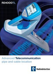
<strong>High</strong> <strong>Voltage</strong> <strong>'Non</strong>-<strong>Persistent'</strong> <strong>Fault</strong> <strong>Finding</strong><strong>Cable</strong> <strong>and</strong> <strong>Cable</strong> <strong>Fault</strong> Locating - Part 4This is the last of a four part series on cable <strong>and</strong> fault locating technologies that are in commonuse today. This installment addresses using high voltage surge generators also known as'Thumpers'. The previous articles have centered on what are basically low voltage test methods,cable locators, a-frames, <strong>and</strong> TDRs are all limited to between 5 <strong>and</strong> 50 volts. This means thefaults must be 'persistent' or always in a faulted state. In the electrical industry, there are somefaults that just don't show up under these conditions.We often need thous<strong>and</strong>s or tens of thous<strong>and</strong>s of volts to make the fault fail. This is where thethumper comes in. It is a portable source of high voltage. Common models put out 32 kV ormore but equally important to this specification is the amount of power that is available. Morepower will make a louder noise <strong>and</strong> make certain faults show up. The need to build up <strong>and</strong> storethis power means most thumpers put out a DC voltage.Thumpers have been around for the better part of the 20 th century but as with all technology,features <strong>and</strong> methods have improved for greater accuracy, easier use <strong>and</strong> interpretation of results.The original thumpers were just that, they repeatedly connected the high voltage to the cableunder test (CUT). Linemen would walk along the path of the cable listening for the 'whumph'(or sometimes a 'dtik' or a 'plunk') under ground. Different ground conditions, vehicle trafficpatterns <strong>and</strong> fault types can make these sounds hard to discern.<strong>Fault</strong>s aren't always the same, sometimes they happen with relatively little voltage, perhaps only500v if the splice was wet. But when the water vaporizes because of the resulting arc, it nowmay take 10 kV for that same breakdown to fail. To find the fault the voltage usually gets turnedup <strong>and</strong> up until the fault appearsRepeated thumping can have some unfortunate side effects to the CUT. <strong>Fault</strong>s that require ahigher voltage to break down often subject the cable to voltages above the design voltage. Whilethe existing fault was located, other areas of the cable may have been weakened. Statistically,thumped cables fail sooner. For this reason, thumping should be a last resort. Anotherconsideration of thumpers is that they are potentially very dangerous if used by unqualifiedpersonnel. The entire CUT must be isolated <strong>and</strong> protected from contact with apparatus <strong>and</strong>personnel.Advancements in thumper systems started with better listening devices. Mechanical methodslike a stethoscope were the first techniques. Antennas <strong>and</strong> meters were added as the flow ofcurrent makes an electro-magnetic (EM) field. In theory, most of the current is dissipated at thefault <strong>and</strong> the current (<strong>and</strong> hence the EM field) is reduced past the fault. The effectiveness of thistechnique is reduced when the fault is a short to another conductor in the same cable. Thecurrent returns on the other conductor in the same magnitude <strong>and</strong> opposite direction <strong>and</strong> the EMfields effectively cancel one another. Listening is still a good choice <strong>and</strong> all modern productsemploy a mechanical microphone or geophone that is placed directly on the ground over thecable. The amplifier <strong>and</strong> headphones connected to the microphone minimize the external noise<strong>and</strong> make the thump easier to hear.
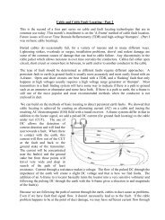
Safety systems were quickly integrated into thumpers. Self-discharge systems, grounding,manual discharge hot-sticks, key switch lock outs <strong>and</strong> other techniques are implemented tominimize the chances of injury. Like most aspects of line work though, there are still many waysto get hurt. Get full training <strong>and</strong> follow all of the manufacturers <strong>and</strong> your companies' guidelines.The next advancement was a visual 'pre-locator', making the thumper more like a high voltageTDR. The pre-locator will usually show the fault with an accuracy better than 10% - 15%. Thiswill cut the distance the lineman needs to walk by 80-90%, allowing more attention to be paid tothe suspected area <strong>and</strong> the faults to be more easily located.Remember that the theory of a TDR is that it transmits a pulse of energy that travels orpropagates along a cable. A portion of the energy will reflect back to the sending end wheneverit passes a relative change in the impedance of the cable. The time the reflections take to returnis proportional to the distance. If we know the approximate speed of the pulse in the cable <strong>and</strong>multiply it by the time the reflection takes to return, the distance to the anomaly is easilycalculated. Most TDR instruments automatically do the math, displaying the distance in feet ormeters.With thumpers there is alarge difference, thatbeing the impedancechange causing thereflection is the arc ofelectricity. The arcdoesn't happen the instantthe pulse gets to the fault,it requires the air betweenthe conductors to ionize<strong>and</strong> become conductive<strong>and</strong> this can add severalmilliseconds onto thetime. As you can see inthe picture to the right,there is a long dead spacebetween the left cursor onthe launch pulse <strong>and</strong> thefirst reflection. The actual distance to the fault from the launch end is the distance between anytwo of the large successive peaks. The peaks are the one pulse bouncing back <strong>and</strong> forth fromlaunch to fault <strong>and</strong> back.
The next advancement in thumper technique <strong>and</strong> technology is commonly called the SecondaryImpulse Method (SIM). This was developed primarily to make trace interpretation easier. Withthe high voltage pulses, the dynamics of the pulse <strong>and</strong> cable create many reflections that are partof the cable <strong>and</strong> the fault may be difficult to detect. Using a low voltage TDR <strong>and</strong> the thumpertogether in an integrated system, a low voltage TDR pulse is taken of the cable <strong>and</strong> stored in adisplay memory. Then the thumper is triggered to send a HV pulse <strong>and</strong> while the arc is burning,the TDR sends the same low voltage pulse which is overlaid upon the first trace. The arc is avery low impedance point that causes the TDR pulse to reflect as it would with a short circuit(which it is). The picture below shows the two traces displayed on top of one another with thedashed cursor at the launch point <strong>and</strong> the solid cursor on the short indication. Now the distanceto the fault is easily read off as 134 meters.Earlier we talked about the voltage <strong>and</strong> power available for the test. The formula for power is P= C * V 2 (power in Joules, C = capacitance <strong>and</strong> V = voltage) <strong>and</strong> the metric units are Joules.This shows using lower voltage will result in the power decreasing by the square, so less isavailable to ionize the air <strong>and</strong> support the thump arc. Newer thumpers have variable capacitance
that can be increased at lower voltages to maintain the same available power. It is entirelypossible that a fault that isn't apparent at a particular voltage will be detectable at a lower voltagewhen there is more stored charge to sustain the arc. This has the advantage of less voltage stresson the CUT.Since the thumper has all this voltage generation, control <strong>and</strong> safety interlocks, most can be usedas a high voltage proof-tester or Hi-Pot as well. The system can be connected to an installedcable or one undergoing a proactive reliability test. The output is enabled <strong>and</strong> stepped up to avoltage above the normal working voltage of the cable <strong>and</strong> held for a set amount of time.Success of this test usually means it is fit for service.Advanced controls include amplification. Control over the vertical amplification of thedisplayed trace allows smaller faults with weak reflections to be detected.A screen zoom function is desirable to allow more accurate placement of a cursor whenmeasuring distances. The resolution of the screen will affect the accuracy of cursor placement<strong>and</strong> the ability to zoom in to improve the resolution will give greater accuracy.Two channels <strong>and</strong>/or memory settings give additional trouble-shooting ability. Due to theirdesign, or environment (temperature <strong>and</strong> moisture for example), some cables may show a 'noisy'trace that is difficult to interpret. Comparing a trace from a non-arcing pulse to an arcing pulsewill often allow the fault to be detected.Training. The best equipment manufactured will not give the required information if theoperators don't underst<strong>and</strong> how to effectively use it. Make sure training <strong>and</strong> applications supportis available, included, <strong>and</strong> utilized when purchasing test equipment.I would be very remiss if I ended this series without thanking Nick Garrioch of Eecol Electric inWinnipeg for his help. I get along much better with the laws of physics than the laws of English.If anyone has cable or cable fault locating questions, please e-mail me at the address below <strong>and</strong> Iwill send you a reply. With your permission, I would like to share some of these situations infuture articles.
WorldleadersTechnicalsupportServicing<strong>and</strong> repairTrainingRadiodetection is a proudmember of the SPX groupof companies, which providetechnical products <strong>and</strong> servicesolutions worldwide.Radiodetection <strong>and</strong> itsassociated companies specializein the design <strong>and</strong> manufactureof products for the location <strong>and</strong>maintenance of undergroundpipes <strong>and</strong> cables. Our aim isto be viewed as the supplier ofchoice of ‘high performance’quality equipment using advancedproduct technologies. We arealso committed to both designinnovation <strong>and</strong> customer support.Radiodetection equipmentusers have easy access totechnical support. A call to yourregional representative, or theRadiodetection head office,will put you in contact withour team of field-experiencedtechnical experts.Radiodetection has a teamof factory-trained servicetechnicians <strong>and</strong> dedicatedservice facilities accreditedto ISO 9000. Turnaroundis fast, <strong>and</strong> costs are verycompetitive. All repairs carrya six month warranty.Product training for youroperators <strong>and</strong> training personnelis available on your site, or atRadiodetection’s headquarters.Training is with qualifiedinstructors <strong>and</strong> each traineereceives a certificate to confirmthey have received the training.AmericaRadiodetection154 Portl<strong>and</strong> RoadBridgton, ME 04009, USATel: +1 (207) 647 9495Toll Free: +1 (877) 247 3797Fax: +1 (207) 647 9496Email: bridgton@radiodetection.spx.comPearpoint72055 Corporate WayThous<strong>and</strong> Palms CA 92276, USATel: +1 800 688 8094Tel: +1 760 343 7350Fax: +1 760 343 7351Email: pearpoint@radiodetection.spx.comRadiodetection (Canada)Unit 34, 344 Edgeley Blvd.Concord, Ontario, Canada L4K 4B7Tel: +1 (905) 660 9995Toll Free: +1 (800) 665 7953Fax: +1 (905) 660 9579Email: support@radiodetection.caTo see the full range of products <strong>and</strong>services provided by Radiodetection visit:www.radiodetection.comEuropeRadiodetection products are under continuous development <strong>and</strong> are subject to change, we reserve the right toalter or amend any published specification without notice. StrikeAlert <strong>and</strong> AvoidanceScan are trademarks ofRadiodetection Ltd. Copyright 2007 Radiodetection Limited. All rights reserved.Radiodetection Ltd. is a subsidiary of SPX Corporation.Radiodetection (UK)Western DriveBristol BS14 0AF, UKTel: +44 (0) 117 976 7776Fax: +44 (0) 117 976 7775Email: sales.uk@radiodetection.spx.comRadiodetection (France)13 Gr<strong>and</strong>e Rue, 76220Neuf Marché, FranceTel: +33 (0) 232 8993 60Fax: +33 (0) 235 9095 58Email: infos@radiodetection.comRadiodetection (Benelux)Industriestraat 11, NL 7041GD’s-Heerenberg, Netherl<strong>and</strong>sTel: +31 (0) 314 66 47 00Fax: +31 (0) 314 66 41 30Email: info@radiodetection.nlRadiodetection (Germany)Groendahlscher Weg 118D-46446 Emmerich am Rhein, GermanyTel: +49 (0) 28 51 92 37 20Fax: +49 (0) 28 51 92 37 520E-Mail: info@radiodetection.deAsia-PacificRadiodetection (Asia-Pacific)Room 708, CC Wu Building302-308 Hennessy Road, Wan ChaiHong Kong SAR, ChinaTel: +852 2110 8160Fax: +852 2110 9681Email: chinasales@radiodetection.spx.comRadiodetection (China)Hong Fu Group Office Building Room 322-326Bei Qi Jia Township, Changping DistrictBeijing 102209, ChinaTel: +86 (0) 10 8975 5540Fax: +86 (0) 10 8975 5640Email: china.service@radiodetection.spx.comRadiodetection (Australia)Mactek Pty. LtdUnit 14, 5-7 Prosperity ParadeWarriewood NSW 2102, AustraliaTel: +61 (0) 2 9979 8555Fax: +61 (0) 2 9979 7733Email: mactek@mactek.com.au