Enclosure - Recom International Power Gmbh
Enclosure - Recom International Power Gmbh
Enclosure - Recom International Power Gmbh

Create successful ePaper yourself
Turn your PDF publications into a flip-book with our unique Google optimized e-Paper software.
Issue Date: 2011-02-14 Page 1 of 47 Report Reference # 1008095-CB<br />
Test Report issued under<br />
the responsibility of:<br />
UL <strong>International</strong> Demko A/S<br />
TEST REPORT<br />
IEC 60950-1:2005 (2nd Edition)<br />
Information technology equipment - Safety -<br />
Part 1: General requirements<br />
Report Reference No .................. : 1008095-CB<br />
Date of issue ................................. : 2011-02-14<br />
Total number of pages .................. : 47<br />
CB Testing Laboratory ............... : Superior Product Consulting, Inc.<br />
Address ......................................... : 3rd Fl, 10 Alley 6, Lane 235 Pao Chiao Rd, Hsin-Tien, Taipei, Taiwan<br />
Applicant's name ........................ :<br />
Address ......................................... :<br />
Test specification:<br />
RECOM ELECTRONIC GMBH<br />
OTTO HAHN STR 60<br />
63303 DREIEICH GERMANY<br />
Standard ....................................... : IEC 60950-1:2005 (Second Edition)<br />
Test procedure .............................. : CB Scheme<br />
Non-standard test method ............ : N/A<br />
Test Report Form No. ................. : IEC60950_1A<br />
Test Report Form originator ......... : SGS Fimko Ltd<br />
Master TRF ................................... : 2009-09<br />
Copyright © 2009 IEC System for Conformity Testing and Certification of Electrical Equipment<br />
(IECEE), Geneva, Switzerland. All rights reserved.<br />
This publication may be reproduced in whole or in part for non-commercial purposes as long as the IECEE is<br />
acknowledged as copyright owner and source of the material. IECEE takes no responsibility for and will not<br />
assume liability for damages resulting from the reader's interpretation of the reproduced material due to its<br />
placement and context.<br />
If this test Report is used by non-IECEE members, the IECEE/IEC logo and the reference to the CB Scheme<br />
procedure shall be removed.<br />
This report is not valid as a CB Test Report unless signed by an approved CB Testing Laboratory and<br />
appended to a CB Test Certificate issued by an NCB in accordance with IECEE 02.<br />
TRF No: IEC60950_1A UL <strong>International</strong> Demko A/S
Issue Date: 2011-02-14 Page 2 of 47 Report Reference # 1008095-CB<br />
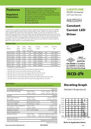
Test item description .................. : DC/DC Converters<br />
Trade Mark ................................... : RECOM<br />
Manufacturer ................................. : RECOM ELECTRONIC GMBH<br />
OTTO HAHN STR 60<br />
63303 DREIEICH GERMANY<br />
Model/Type reference ................... : 1) RECz-xxyySRWa/b/A/M/c and<br />
RECz-xxyyDRWa/b/A/M/c<br />
(z = 8 or 10; xx = 05, 12, 24 or 48; yy = 3.3, 05, 12 or 15;<br />
a = Z or none; b = H2 or H3; c = SMD, X1 to X9 or none)<br />
2) REC15-xySa/b/c and REC15-xyDa/b/c<br />
( x = 05, 12, 24 or 48; y = 3.3, 3.4, 05, 5.1, 12 or 15;<br />
a = Z or none; b = H2 or H3; c = X1 to X9 or none)<br />
Rating ........................................... : Input and Output ratings: See <strong>Enclosure</strong> Miscellaneous ID 7-02 for<br />
details.<br />
TRF No: IEC60950_1A UL <strong>International</strong> Demko A/S
Issue Date: 2011-02-14 Page 3 of 47 Report Reference # 1008095-CB<br />
Testing procedure and testing location:<br />
[x] CB Testing Laboratory<br />
Testing location / address ..............: Superior Product Consulting, Inc. 3rd Fl, 10 Alley 6, Lane 235<br />
Pao Chiao Rd, Hsin-Tien, Taipei, Taiwan<br />
[ ] Associated CB Test Laboratory<br />
Testing location / address ..............:<br />
Tested by (name + signature) ........: Judy Jeng<br />
Approved by (+ signature)..............: Allen Huang<br />
[ ] Testing Procedure: TMP<br />
Tested by (name + signature) ........:<br />
Approved by (+ signature)..............:<br />
Testing location / address ..............:<br />
[ ] Testing Procedure: WMT<br />
Tested by (name + signature) ........:<br />
Witnessed by (+ signature) ............:<br />
Approved by (+ signature)..............:<br />
Testing location / address ..............:<br />
[ ] Testing Procedure: SMT<br />
Tested by (name + signature) ........:<br />
Approved by (+ signature)..............:<br />
Supervised by (+ signature) ...........:<br />
Testing location / address ..............:<br />
[ ] Testing Procedure: RMT<br />
Tested by (name + signature) ........:<br />
Approved by (+ signature)..............:<br />
Supervised by (+ signature) ...........:<br />
Testing location / address ..............:<br />
TRF No: IEC60950_1A UL <strong>International</strong> Demko A/S
Issue Date: 2011-02-14 Page 4 of 47 Report Reference # 1008095-CB<br />
Summary Of Testing<br />
Unless otherwise indicated, all tests were conducted at Superior Product Consulting, Inc. 3rd Fl, 10 Alley 6,<br />
Lane 235 Pao Chiao Rd, Hsin-Tien, Taipei, Taiwan.<br />
Tests performed (name of test and test clause) Testing location / Comments<br />
Maximum Output Voltage, Current, and Volt-Ampere<br />
Measurement (1.2.2.1)<br />
Input: Single-Phase (1.6.2)<br />
Energy Hazard Measurements (2.1.1.5, 2.1.2, 1.2.8.10)<br />
SELV Reliability (2.2.2, 2.2.3, 2.2.4, Part 22 6.1)<br />
Humidity (2.9.1, 2.9.2, 5.2.2)<br />
Determination of Working Voltage; Working Voltage<br />
Measurement (2.10.2)<br />
Heating (4.5.1, 1.4.12, 1.4.13)<br />
Electric Strength (5.2.2)<br />
Component Failure (5.3.1, 5.3.4, 5.3.7)<br />
Transformer Abnormal Operation (5.3.3, 5.3.7b, Annex<br />
C.1)<br />
<strong>Power</strong> Supply Output Short-Circuit/Overload (5.3.7)<br />
Summary of Compliance with National Differences:<br />
AT, AU, BE, BG, BR, CA, CH, CN, CY, CZ, DE, DK, EE, ES, EU, FI, FR, GB, GR, HU, IE, IL, IS, IT,<br />
JP, KR, LT, LU, LV, MT, NL, NO, PL, PT, RO, SE, SG, SI, SK, UA, US<br />
Copy of Marking Plate - Refer to <strong>Enclosure</strong> titled Marking Plate for copy.<br />
TRF No: IEC60950_1A UL <strong>International</strong> Demko A/S
Issue Date: 2011-02-14 Page 5 of 47 Report Reference # 1008095-CB<br />
Test item particulars :<br />
Equipment mobility ..............................................: for building-in<br />
Connection to the mains ......................................: To be determined in end product<br />
Operating condition ..............................................: continuous<br />
Access location ....................................................: operator accessible<br />
Over voltage category (OVC) ..............................: --<br />
Mains supply tolerance (%) or absolute mains supply<br />
values ..................................................................: No direct connection<br />
Tested for IT power systems ...............................: No<br />
IT testing, phase-phase voltage (V) .....................: N/A<br />
Class of equipment ..............................................: Special Application - TNV-2<br />
Considered current rating (A) ..............................: 18A<br />
Pollution degree (PD) ..........................................: PD 2<br />
IP protection class ...............................................: IP X0<br />
Altitude of operation (m) ......................................: up to 2000 m<br />
Altitude of test laboratory (m) ..............................: 60 m<br />
Mass of equipment (kg) .......................................: 0.02 for REC8-xxxxSRW/DRW, REC10xxxxSRW/DRW-series<br />
0.03 for REC15-xxyySa/bb/c and REC15-xxyyDa/bb/c<br />
-series<br />
Possible test case verdicts:<br />
- test case does not apply to the test object ........: N / A<br />
- test object does meet the requirement ..............: P(Pass)<br />
- test object does not meet the requirement ........: F(Fail)<br />
Testing:<br />
Date(s) of receipt of test item ..............................: 2010-08-31<br />
Date(s) of Performance of tests ...........................: 2010-10-20 to 2010-12-15<br />
General remarks:<br />
The test results presented in this report relate only to the object tested.<br />
This report shall not be reproduced, except in full, without the written approval of the Issuing testing<br />
laboratory.<br />
"(see <strong>Enclosure</strong> #)" refers to additional information appended to the report.<br />
"(see appended table)" refers to a table appended to the report.<br />
Throughout this report a point is used as the decimal separator.<br />
GENERAL PRODUCT INFORMATION:<br />
Report Summary<br />
TRF No: IEC60950_1A UL <strong>International</strong> Demko A/S
Issue Date: 2011-02-14 Page 6 of 47 Report Reference # 1008095-CB<br />
All applicable tests according to the referenced standard(s) have been carried out.<br />
Product Description<br />
The equipment is a DC-DC converter for building in Information technology equipment and consists of<br />
electronic components mounted on PWB.<br />
The REC8-xxyySRW/DRW, REC10-xxyySRW/DRW-series offer single and dual regulated outputs in a<br />
DIP24 package with 2kV or 3kV isolation options and are suitable for Information technology equipment<br />
applications. Remote on/off control is standard and SMD pinning is offered with the /SMD option.<br />
The REC15-xxyySa/bb/c and REC15-xxyyDa/bb/c -series offer single and dual regulated outputs in a 2”x1”<br />
package with 2kVDC or 3kVDC isolation options and are suitable for Information technology equipment<br />
applications. Remote on/off control is standard.<br />
Model Differences<br />
All models are similar except for model designations, output power, output voltage, Package Size and<br />
transformer.<br />
Models REC8-xxyySRWa/bb/A/M/c and REC8-xxyyDRWa/bb/A/M/c series are identical to models REC10xxyySRWa/bb/A/M/c<br />
and REC10-xxyyDRWa/bb/A/M/c series except for model designation, transformer and<br />
output.<br />
Models REC15-xxyySa/bb/c and REC15-xxyyDa/bb/c series are identical to models REC10xxyySRWa/bb/A/M/c<br />
and REC10-xxyyDRWa/bb/A/M/c series except for model designation, output rating,<br />
transformer and Package Size.<br />
Models REC8-xxyySRWa/bb/A/M/c, REC10-xxyySRWa/bb/A/M/c and REC15-xxyySa/bb/c for single output<br />
Models REC8-xxyyDRWa/bb/A/M/c, REC10-xxyyDRWa/bb/A/M/c and REC15-xxyyDa/bb/c for dual output<br />
Model nomenclature:<br />
RECz-xxyySRWa/bb/A/M/c and RECz-xxyyDRWa/bb/A/M/c<br />
z can be 8 or 10, denote output power wattage<br />
When z is 8, Input voltage without a Z behind SRW or DRW xx=05 (4.5-9V), 12 (9-18), 24 (18-36V), 48 (36-<br />
75V)<br />
When z is 10, Input voltage without a Z behind SRW or DRW xx=12 (9-18), 24 (18-36V), 48 (36-75V)<br />
Input voltage with a Z behind SRW or DRW xx= 24 (9-36V), 48 (18-75V)<br />
Output voltage for SRW type yy can be 3.3, 05, 12 and 15, denote output voltage 3.3V, 5V, 12V and 15V<br />
Output voltage for DRW type yy can be 05, 12 and 15, denote dual output voltage ±5V, ±12V and ±15V<br />
a can be blank or Z (Input voltage see above)<br />
bb can be H2 or H3<br />
c can be / SMD or /X1 to /X9 or blank<br />
SMD for PIN SMD package<br />
blank PIN DIP package<br />
/X1 = Special customer requirement that does not affect safety*<br />
/X2 = Reduced pin out (one or more pins may be omitted during manufacture)<br />
/X3 = Reduced power (maximum converter power will be reduced to optimize<br />
efficiency at lower loads)<br />
/X4 = Reduced quiescent current (converter component values will be fine<br />
tuned to minimize no-load input current: this may reduce the operating<br />
temperature range of the converter)<br />
/X5 = reduced inrush current (component values optimized to reduce inrush<br />
TRF No: IEC60950_1A UL <strong>International</strong> Demko A/S
Issue Date: 2011-02-14 Page 7 of 47 Report Reference # 1008095-CB<br />
current)<br />
/X6 = non-standard isolation test (isolation will be tested according to a<br />
customer-specified protocol)<br />
/X7 = non-standard operating frequency (operating frequency adjusted to<br />
avoid interference effects in customer’s application)<br />
/X8 = Special customer requirement that does not affect safety*<br />
/X9 = Special customer requirement that does not affect safety*<br />
* examples of /X1, /X8 or /X9 suffixes are customer requests for<br />
non-standard case color, non-standard pin length, etc.<br />
REC15-xxyySa/bb/c and REC15-xxyyDa/bb/c<br />
Input voltage without a Z behind S or D xx=12 (9-18), 24 (18-36V), 48 (36-75V)<br />
Input voltage with a Z behind S or D xx= 24 (9-36V), 48 (18-75V)<br />
Output voltage for S type yy can be 3.4, 5.1, 12 and 15, denote output voltage 3.4V, 5.1V, 12V and 15V<br />
Output voltage for D type yy can be 05, 12 and 15, denote dual output voltage ±5V, ±12V and ±15V<br />
a can be blank or Z (Input voltage see above)<br />
bb can be H2 or H3<br />
c can be /X1 = Special customer requirement that does not affect safety*<br />
/X2 = Reduced pinout (one or more pins may be omitted during manufacture)<br />
/X3 = Reduced power (maximum converter power will be reduced to optimise<br />
efficiency at lower loads)<br />
/X4 = Reduced quiescent current (converter component values will be fine<br />
tuned to minimise no-load input current: this may reduce the operating<br />
temperature range of the converter)<br />
/X5 = reduced inrush current (component values optimised to reduce inrush<br />
current)<br />
/X6 = non-standard isolation test (isolation will be tested according to a<br />
customer-specified protocol)<br />
/X7 = non-standard operating frequency (operating frequency adjusted to<br />
avoid interference effects in customer’s application)<br />
/X8 = Special customer requirement that does not affect safety*<br />
/X9 = Special customer requirement that does not affect safety*<br />
* examples of /X1, /X8 or /X9 suffixes are customer requests for<br />
non-standard case colour, non-standard pin length, etc.<br />
Additional Information<br />
The product was investigated to the following additional standards: EN 60950-1:2006+A11:2009 (which<br />
includes all European national differences, including those specified in this test report).<br />
Licenses for critical components to be furnished by applicant upon request.<br />
The artwork below may be only a draft. The use of certification marks on a product must be authorized by the<br />
respective NCBs that own these marks.<br />
The artwork provided is representative of all models in the Series.<br />
Technical Considerations<br />
� The product was submitted and evaluated for use at the maximum ambient temperature (Tma)<br />
permitted by the manufacturer’s specification of: The product can be operated at a maximum<br />
TRF No: IEC60950_1A UL <strong>International</strong> Demko A/S
Issue Date: 2011-02-14 Page 8 of 47 Report Reference # 1008095-CB<br />
ambient temperature of 75°C for REC8-series, the product can be operated at a maximum ambient<br />
temperature of 70°C for REC10-series, the product can be operated at a maximum ambient<br />
temperature of 71°C for REC15-xyS/bb/c and REC15-xyD/bb/c, the product can be operated at a<br />
maximum ambient temperature of 65°C for REC15-xySZ/bb/c and REC15-xyDZ/bb/c.<br />
� The product was investigated to the following additional standards: EN 60950-1:2006+ A11:2009<br />
(which includes all European national differences, including those specified in this test report).<br />
� The following are available from the Applicant upon request: Installation (Safety) Instructions /<br />
Manual<br />
Engineering Conditions of Acceptability<br />
When installed in an end-product, consideration must be given to the following:<br />
� The end-product Electric Strength Test is to be based upon a maximum working voltage of: Input-<br />
Output: 86 Vrms, 136 V peak<br />
� The following secondary output circuits are SELV: All Outputs<br />
� The following secondary output circuits are at non-hazardous energy levels: All Outputs<br />
� The power supply terminals and/or connectors are: Suitable for factory wiring only<br />
� The investigated Pollution Degree is: 2<br />
� Proper bonding to the end-product main protective earthing termination is: Not required<br />
� The following end-product enclosures are required: Fire, Electrical,<br />
� Abnormal/Component Failure Tests were conducted with an power source capacity 18 A. Repeated<br />
tests in the end-use application shall be considered while installing different rated protective devices.<br />
� DC/DC converter is providing Basic isolation from SELV to Hazardous voltage secondary circuit<br />
consider as TNV-2. Per Clause 2.2.4, 2.3.2.2, the DC/DC converter has been tested by electrical<br />
strength test of insulation from transformer input to output for Basic insulation in accordance with<br />
sub-clause 5.2.2. The actual test voltage DC 3000V is an elevated test voltage from table 5B<br />
according to manufacturer's request.<br />
Factory Location(s):<br />
<strong>Recom</strong> Manufacturing and Trading Ltd,<br />
2F, No. 206, Feng Jen Road, Feng Shan,<br />
TRF No: IEC60950_1A UL <strong>International</strong> Demko A/S
Issue Date: 2011-02-14 Page 9 of 47 Report Reference # 1008095-CB<br />
Kaohsiung County,<br />
Taiwan, R.O.C<br />
Attachments to Test Report<br />
National Differences (22 pages)<br />
<strong>Enclosure</strong>s ( 41 pages)<br />
TRF No: IEC60950_1A UL <strong>International</strong> Demko A/S
Issue Date: 2011-02-14 Page 10 of 47 Report Reference # 1008095-CB<br />
IEC/EN 60950-1<br />
Clause Requirement + Test Result - Remark Verdict<br />
1 GENERAL Pass<br />
1.5 Components Pass<br />
1.5.1 General<br />
Comply with IEC 60950-1 or relevant component<br />
standard<br />
TRF No: IEC60950_1A UL <strong>International</strong> Demko A/S<br />
Pass<br />
(see appended table 1.5.1) Pass<br />
1.5.2 Evaluation and testing of components Components certified to IEC<br />
harmonized standard and<br />
checked for correct<br />
application.<br />
1.5.3 Thermal controls<br />
Components, for which no<br />
relevant IEC-Standard exist,<br />
have been tested under the<br />
conditions occurring in the<br />
equipment, using applicable<br />
parts of IEC 60950-1.<br />
Components not certified are<br />
used in accordance with their<br />
ratings and they comply with<br />
applicable parts of IEC 60950-<br />
1 and the relevant component<br />
Standard.<br />
1.5.4 Transformers See Annex C. Pass<br />
1.5.5 Interconnecting cables<br />
1.5.6 Capacitors bridging insulation<br />
1.5.7 Resistors bridging insulation<br />
1.5.7.1 Resistors bridging functional, basic or<br />
supplementary insulation<br />
1.5.7.2 Resistors bridging double or reinforced insulation<br />
between a.c. mains and other circuits<br />
1.5.7.3 Resistors bridging double or reinforced insulation<br />
between a.c. mains and antenna or coaxial cable<br />
1.5.8 Components in equipment for IT power systems<br />
1.5.9 Surge suppressors<br />
1.5.9.1 General<br />
1.5.9.2 Protection of VDRs<br />
1.5.9.3 Bridging of functional insulation by a VDR<br />
Pass<br />
N/A<br />
N/A<br />
N/A<br />
N/A<br />
N/A<br />
N/A<br />
N/A<br />
N/A<br />
N/A<br />
N/A<br />
N/A<br />
N/A
Issue Date: 2011-02-14 Page 11 of 47 Report Reference # 1008095-CB<br />
IEC/EN 60950-1<br />
Clause Requirement + Test Result - Remark Verdict<br />
1.5.9.4 Bridging of basic insulation by a VDR<br />
1.5.9.5 Bridging of supplementary, double or reinforced<br />
insulation by a VDR<br />
1.6 <strong>Power</strong> interface Pass<br />
1.6.1 AC power distribution systems Not connected to AC Mains. N/A<br />
1.6.2 Input current This is a build-in power<br />
module, there is no rated<br />
current declare by<br />
manufacturer.<br />
1.6.3 Voltage limit of hand-held equipment The unit is not a hand-held<br />
equipment.<br />
1.6.4 Neutral conductor DC input only. N/A<br />
1.7 Marking and instructions Pass<br />
1.7.1 <strong>Power</strong> rating Unit is no direct connection<br />
Mains supply and intended for<br />
building-in. To be evaluated in<br />
end product.<br />
Rated voltage(s) or voltage range(s) (V)................: Input: 4.5 -9 Vdc for Model<br />
REC8-05yySRW or<br />
DRW/b/A/M/c.<br />
Input: 9-18 Vdc for Model<br />
REC8-12yySRW or<br />
DRW/b/A/M/c and REC10-<br />
12yySRW or DRW/b/A/M/c<br />
and REC15-12yyS or D/b/c.<br />
Input: 18-36 Vdc for Model<br />
REC8-24yySRW or<br />
DRW/b/A/M/c and REC10-<br />
24yySRW or DRW/b/A/M/c<br />
and REC15-24yyS or D/b/c.<br />
Input: 36-75 Vdc for Model<br />
REC8-48yySRW or<br />
DRW/b/A/M/c and REC10-<br />
48yySRW or DRW/b/A/M/c<br />
and REC15-48yyS or D/b/c.<br />
Input: 9-36 Vdc for Model<br />
REC8-24yySRW or<br />
DRWZ/b/A/M/c and REC10-<br />
24yySRW or DRWZ/b/A/M/c<br />
and REC15-24yyS or DZ/b/c.<br />
Input: 18-75 Vdc for Model<br />
REC8-48yySRW or<br />
DRWZ/b/A/M/c and REC10-<br />
48yySRW or DRWZ/b/A/M/c<br />
and REC15-48yyS or DZ/b/c.<br />
TRF No: IEC60950_1A UL <strong>International</strong> Demko A/S<br />
N/A<br />
N/A<br />
Pass<br />
N/A<br />
Pass<br />
Pass
Issue Date: 2011-02-14 Page 12 of 47 Report Reference # 1008095-CB<br />
IEC/EN 60950-1<br />
Clause Requirement + Test Result - Remark Verdict<br />
Symbol for nature of supply, for d.c. only...............: Evaluation shall be considered<br />
in the end product.<br />
Rated frequency or rated frequency range (Hz) ....: DC input only N/A<br />
Rated current (mA or A) .........................................: This is a build-in power<br />
module, there is no rated<br />
current declare by<br />
manufacturer.<br />
Manufacturer's name or trademark or identification<br />
mark .......................................................................:<br />
TRF No: IEC60950_1A UL <strong>International</strong> Demko A/S<br />
N/A<br />
Pass<br />
RECOM Pass<br />
Model identification or type reference ....................: 1) RECz-xxyySRWa/b/A/M/c<br />
and<br />
RECz-xxyyDRWa/b/A/M/c<br />
(z = 8 or 10; xx = 05, 12, 24 or<br />
48; yy = 3.3, 05, 12 or 15;<br />
a = Z or none; b = H2 or H3; c<br />
= SMD, X1 to X9 or none)<br />
2) REC15-xySa/b/c and<br />
REC15-xyDa/b/c<br />
( x = 05, 12, 24 or 48; y = 3.3,<br />
3.4, 05, 5.1, 12 or 15;<br />
a = Z or none; b = H2 or H3; c<br />
= X1 to X9 or none)<br />
Symbol for Class II equipment only........................:<br />
Other markings and symbols .................................: Additional symbols may be<br />
provided when submitted for<br />
National Approval.<br />
1.7.2 Safety instructions and marking Evaluation shall be considered<br />
in the end product.<br />
1.7.2.1 General<br />
1.7.2.2 Disconnect devices<br />
1.7.2.3 Overcurrent protective device Evaluation shall be considered<br />
in the end product.<br />
1.7.2.4 IT <strong>Power</strong> distribution systems<br />
1.7.2.5 Operator access with a tool<br />
1.7.2.6 Ozone<br />
1.7.3 Short duty cycles The equipment is intended for<br />
continuous operation.<br />
1.7.4 Supply voltage adjustment .....................................: No voltage adjustment. N/A<br />
Method and means of adjustment; reference to<br />
installation instructions ...........................................:<br />
1.7.5 <strong>Power</strong> outlets on the equipment.............................: No standard power outlets are<br />
provided.<br />
Pass<br />
N/A<br />
N/A<br />
N/A<br />
N/A<br />
N/A<br />
N/A<br />
N/A<br />
N/A<br />
N/A<br />
N/A<br />
N/A<br />
N/A
Issue Date: 2011-02-14 Page 13 of 47 Report Reference # 1008095-CB<br />
IEC/EN 60950-1<br />
Clause Requirement + Test Result - Remark Verdict<br />
1.7.6 Fuse identification (marking, special fusing<br />
characteristics, cross-reference)............................:<br />
1.7.7 Wiring terminals<br />
1.7.7.1 Protective earthing and bonding terminals.............:<br />
TRF No: IEC60950_1A UL <strong>International</strong> Demko A/S<br />
No fuses are provided. N/A<br />
1.7.7.2 Terminals for a.c. mains supply conductors Not connect to AC Mains. N/A<br />
1.7.7.3 Terminals for d.c. mains supply conductors Evaluation shall be considered<br />
in the end product.<br />
1.7.8 Controls and indicators<br />
1.7.8.1 Identification, location and marking........................:<br />
1.7.8.2 Colours ...................................................................: Only functional indicators use<br />
color.<br />
1.7.8.3 Symbols according to IEC 60417...........................:<br />
1.7.8.4 Markings using figures ...........................................:<br />
1.7.9 Isolation of multiple power sources........................:<br />
1.7.10 Thermostats and other regulating devices.............: N/A<br />
1.7.11 Durability Permanently lasermark. Pass<br />
1.7.12 Removable parts No marking is located on<br />
removable part.<br />
1.7.13 Replaceable batteries ............................................: There are no lithium batteries<br />
in the equipment.<br />
Language(s) ...........................................................:<br />
1.7.14 Equipment for restricted access locations .............:<br />
2 PROTECTION FROM HAZARDS Pass<br />
2.1 Protection from electric shock and energy hazards N/A<br />
2.1.1 Protection in operator access areas The equipment is intended for<br />
installation in a building-in<br />
component, evaluation shall be<br />
considered in the end product.<br />
2.1.1.1 Access to energized parts The equipment is considered<br />
as a building-in component,<br />
evaluation shall be considered<br />
in the end product.<br />
Test by inspection ..................................................: The equipment is considered<br />
as a building-in component,<br />
evaluation shall be considered<br />
in the end product.<br />
N/A<br />
N/A<br />
N/A<br />
N/A<br />
N/A<br />
N/A<br />
N/A<br />
N/A<br />
N/A<br />
Pass<br />
N/A<br />
-<br />
N/A<br />
N/A<br />
N/A<br />
N/A
Issue Date: 2011-02-14 Page 14 of 47 Report Reference # 1008095-CB<br />
IEC/EN 60950-1<br />
Clause Requirement + Test Result - Remark Verdict<br />
Test with test finger (Figure 2A).............................: The equipment is considered<br />
as a building-in component,<br />
evaluation shall be considered<br />
in the end product.<br />
Test with test pin (Figure 2B) .................................: The equipment is considered<br />
as a building-in component,<br />
evaluation shall be considered<br />
in the end product.<br />
Test with test probe (Figure 2C).............................:<br />
2.1.1.2 Battery compartments No battery compartments<br />
provided as part of the<br />
equipment.<br />
2.1.1.3 Access to ELV wiring No ELV circuits provided as<br />
part of the equipment.<br />
Working voltage (Vpeak or Vrms); minimum<br />
distance through insulation (mm)...........................:<br />
2.1.1.4 Access to hazardous voltage circuit wiring The equipment is considered<br />
as a building-in component,<br />
evaluation shall be considered<br />
in the end product.<br />
2.1.1.5 Energy hazards ......................................................: The equipment is considered<br />
as a building-in component,<br />
evaluation shall be considered<br />
in the end product.<br />
2.1.1.6 Manual controls<br />
2.1.1.7 Discharge of capacitors in equipment DC Source N/A<br />
Measured voltage (V); time-constant (s)................:<br />
2.1.1.8 Energy hazards - d.c. mains supply Unit is intended to be used as<br />
a building-in component. To<br />
be evaluated in end product<br />
a) Capacitor connected to the d.c. mains supply ...:<br />
b) Internal battery connected to the mains supply .:<br />
2.1.1.9 Audio amplifiers......................................................:<br />
2.1.2 Protection in service access areas Unit is intended to be used as<br />
a building-in component. To<br />
be evaluated in end product<br />
2.1.3 Protection in restricted access locations<br />
2.2 SELV circuits Pass<br />
2.2.1 General requirements SELV levels are maintained<br />
after single fault condition.<br />
TRF No: IEC60950_1A UL <strong>International</strong> Demko A/S<br />
N/A<br />
N/A<br />
N/A<br />
N/A<br />
N/A<br />
-<br />
N/A<br />
N/A<br />
N/A<br />
-<br />
N/A<br />
N/A<br />
N/A<br />
N/A<br />
N/A<br />
N/A<br />
Pass
Issue Date: 2011-02-14 Page 15 of 47 Report Reference # 1008095-CB<br />
IEC/EN 60950-1<br />
Clause Requirement + Test Result - Remark Verdict<br />
2.2.2 Voltages under normal conditions (V)....................: All accessible voltages are<br />
less than 42.4 V peak or 60<br />
Vdc and are classified as<br />
SELV.<br />
2.2.3 Voltages under fault conditions (V) ........................: Under fault conditions,<br />
voltages never exceed 71 V<br />
peak and 120 Vdc and do not<br />
exceed 42.4 V peak or 60 Vdc<br />
for more than 0.2 second.<br />
2.2.4 Connection of SELV circuits to other circuits .........: SELV circuits are only<br />
connected to other SELV<br />
circuits.<br />
2.3 TNV circuits Pass<br />
2.3.1 Limits DC supply circuit considered<br />
as TNV-2.<br />
Type of TNV circuits...............................................: TNV-2 -<br />
2.3.2 Separation from other circuits and from accessible<br />
parts<br />
Pass<br />
2.3.2.1 General requirements See sub-clause 2.10.5.13. Pass<br />
2.3.2.2 Protection by basic insulation<br />
N/A<br />
2.3.2.3 Protection by earthing<br />
2.3.2.4 Protection by other constructions...........................:<br />
2.3.3 Separation from hazardous voltages<br />
Insulation employed ...............................................:<br />
2.3.4 Connection of TNV circuits to other circuits<br />
Insulation employed ...............................................:<br />
2.3.5 Test for operating voltages generated externally<br />
2.4 Limited current circuits N/A<br />
2.5 Limited power sources N/A<br />
2.6 Provisions for earthing and bonding N/A<br />
TRF No: IEC60950_1A UL <strong>International</strong> Demko A/S<br />
Pass<br />
Pass<br />
Pass<br />
Pass<br />
N/A<br />
N/A<br />
N/A<br />
-<br />
N/A<br />
-<br />
N/A
Issue Date: 2011-02-14 Page 16 of 47 Report Reference # 1008095-CB<br />
IEC/EN 60950-1<br />
Clause Requirement + Test Result - Remark Verdict<br />
2.7 Overcurrent and earth fault protection in primary circuits N/A<br />
2.8 Safety interlocks N/A<br />
2.9 Electrical insulation Pass<br />
2.9.1 Properties of insulating materials Natural rubber, materials<br />
containing asbestos and<br />
hygroscopic materials are not<br />
used as insulation.<br />
2.9.2 Humidity conditioning Electric strength test was<br />
conducted after the humidity<br />
treatment for 48 hours.<br />
Relative humidity (%), temperature (°C) ................: 93%, 30 degree C -<br />
2.9.3 Grade of insulation Basic insulation Pass<br />
2.9.4 Separation from hazardous voltages<br />
Method(s) used ......................................................: The DC/DC converter is<br />
providing Basic isolation from<br />
SELV to Hazardous voltage<br />
secondary circuit. Per Clause<br />
2.2.4, the DC/DC converter<br />
has been tested by electrical<br />
strength test of insulation from<br />
transformer input to output for<br />
Basic insulation in accordance<br />
with sub-clause 5.2.2. The<br />
actual test voltage DC 3000V<br />
is an elevated test voltage<br />
from table 5B according to<br />
manufacturer's request.<br />
2.10 Clearances, creepage distances and distances through insulation Pass<br />
2.10.1 General<br />
2.10.1.1 Frequency ..............................................................:<br />
2.10.1.2 Pollution degrees....................................................: Pollution degree 2. Pass<br />
2.10.1.3 Reduced values for functional insulation See sub-clause 5.3.4. Pass<br />
2.10.1.4 Intervening unconnected conductive parts<br />
2.10.1.5 Insulation with varying dimensions<br />
2.10.1.6 Special separation requirements<br />
TRF No: IEC60950_1A UL <strong>International</strong> Demko A/S<br />
Pass<br />
Pass<br />
Pass<br />
-<br />
Pass<br />
N/A<br />
Pass<br />
N/A<br />
N/A
Issue Date: 2011-02-14 Page 17 of 47 Report Reference # 1008095-CB<br />
IEC/EN 60950-1<br />
Clause Requirement + Test Result - Remark Verdict<br />
2.10.1.7 Insulation in circuits generating starting pulses<br />
2.10.2 Determination of working voltage<br />
2.10.2.1 General<br />
2.10.2.2 RMS working voltage (see appended table 2.10.3<br />
and 2.10.4)<br />
2.10.2.3 Peak working voltage (see appended table 2.10.3<br />
and 2.10.4)<br />
2.10.3 Clearances (see appended table 2.10.3<br />
and 2.10.4)<br />
2.10.3.1 General<br />
2.10.3.2 Mains transient voltages Secondary circuit only, see<br />
sub-clause 2.10.3.6.<br />
a) AC mains supply ................................................:<br />
b) Earthed d.c. mains supplies...............................:<br />
c) Unearthed d.c. mains supplies...........................:<br />
d) Battery operation................................................:<br />
2.10.3.3 Clearances in primary circuits No primary circuits. N/A<br />
2.10.3.4 Clearances in secondary circuits (see appended table 2.10.3<br />
and 2.10.4)<br />
2.10.3.5 Clearances in circuits having starting pulses<br />
2.10.3.6 Transients from a.c. mains supply .........................: Transient voltage of the<br />
secondary circuit that is 1500<br />
Vpeak one step lower from<br />
table 2J in the primary circuit.<br />
2.10.3.7 Transients from d.c. mains supply .........................:<br />
2.10.3.8 Transients from telecommunication networks and<br />
cable distribution systems ......................................:<br />
2.10.3.9 Measurement of transient voltage levels<br />
a) Transients from a mains supply<br />
For an a.c. mains supply ........................................:<br />
For a d.c. mains supply ..........................................:<br />
b) Transients from a telecommunication network<br />
2.10.4 Creepage distances (see appended table 2.10.3 Pass<br />
TRF No: IEC60950_1A UL <strong>International</strong> Demko A/S<br />
N/A<br />
Pass<br />
Pass<br />
Pass<br />
Pass<br />
Pass<br />
Pass<br />
N/A<br />
N/A<br />
N/A<br />
N/A<br />
N/A<br />
Pass<br />
N/A<br />
Pass<br />
N/A<br />
N/A<br />
N/A<br />
N/A<br />
N/A<br />
N/A<br />
N/A
Issue Date: 2011-02-14 Page 18 of 47 Report Reference # 1008095-CB<br />
IEC/EN 60950-1<br />
Clause Requirement + Test Result - Remark Verdict<br />
2.10.4.1 General<br />
2.10.4.2 Material group and comparative tracking index<br />
and 2.10.4)<br />
CTI tests .................................................................: Material group IIIb; 100
Issue Date: 2011-02-14 Page 19 of 47 Report Reference # 1008095-CB<br />
IEC/EN 60950-1<br />
Clause Requirement + Test Result - Remark Verdict<br />
b) Basic, supplementary, reinforced insulation ......:<br />
c) Compliance with Annex U ..................................:<br />
Two wires in contact inside wound component;<br />
angle between 45° and 90°....................................:<br />
2.10.5.13 Wire with solvent-based enamel in wound<br />
components<br />
Pass<br />
Electric strength test...............................................: See Table 5.2.2. -<br />
Routine test<br />
2.10.5.14 Additional insulation in wound components<br />
Working voltage......................................................:<br />
- Basic insulation not under stress .........................: A layer of insulation tape<br />
provide between winding and<br />
core.<br />
- Supplementary, reinforced insulation ..................:<br />
2.10.6 Construction of printed boards<br />
2.10.6.1 Uncoated printed boards<br />
2.10.6.2 Coated printed boards N/A<br />
2.10.6.3 Insulation between conductors on the same inner<br />
surface of a printed board<br />
N/A<br />
2.10.6.4 Insulation between conductors on different layers<br />
of a printed board<br />
Basic insulation. N/A<br />
Distance through insulation<br />
Number of insulation layers (pcs)...........................:<br />
2.10.7 Component external terminations<br />
2.10.8 Tests on coated printed boards and coated<br />
components<br />
2.10.8.1 Sample preparation and preliminary inspection<br />
2.10.8.2 Thermal conditioning<br />
2.10.8.3 Electric strength test<br />
2.10.8.4 Abrasion resistance test<br />
2.10.9 Thermal cycling<br />
TRF No: IEC60950_1A UL <strong>International</strong> Demko A/S<br />
N/A<br />
N/A<br />
N/A<br />
Pass<br />
Pass<br />
N/A<br />
Pass<br />
N/A<br />
Pass<br />
Pass<br />
N/A<br />
N/A<br />
N/A<br />
N/A<br />
N/A<br />
N/A<br />
N/A<br />
N/A<br />
N/A
Issue Date: 2011-02-14 Page 20 of 47 Report Reference # 1008095-CB<br />
IEC/EN 60950-1<br />
Clause Requirement + Test Result - Remark Verdict<br />
2.10.10 Test for Pollution Degree 1 environment and<br />
insulating compound<br />
2.10.11 Tests for semiconductor devices and cemented<br />
joints<br />
2.10.12 Enclosed and sealed parts<br />
3 WIRING, CONNECTIONS AND SUPPLY Pass<br />
3.1 General N/A<br />
3.1.1 Current rating and overcurrent protection<br />
3.1.2 Protection against mechanical damage<br />
3.1.3 Securing of internal wiring<br />
3.1.4 Insulation of conductors<br />
3.1.5 Beads and ceramic insulators The equipment does not have<br />
any beads or similar insulators.<br />
3.1.6 Screws for electrical contact pressure<br />
3.1.7 Insulating materials in electrical connections<br />
3.1.8 Self-tapping and spaced thread screws<br />
3.1.9 Termination of conductors N/A<br />
10 N pull test<br />
3.1.10 Sleeving on wiring No sleeving used as<br />
supplementary insulation.<br />
3.2 Connection to mains supply N/A<br />
3.3 Wiring terminals for connection of external conductors N/A<br />
3.4 Disconnection from the mains supply N/A<br />
3.5 Interconnection of equipment Pass<br />
3.5.1 General requirements<br />
3.5.2 Types of interconnection circuits............................: Interconnection circuits are<br />
only to SELV or TNV-2 .<br />
TRF No: IEC60950_1A UL <strong>International</strong> Demko A/S<br />
N/A<br />
N/A<br />
N/A<br />
N/A<br />
N/A<br />
N/A<br />
N/A<br />
N/A<br />
N/A<br />
N/A<br />
N/A<br />
N/A<br />
N/A<br />
Pass<br />
Pass
Issue Date: 2011-02-14 Page 21 of 47 Report Reference # 1008095-CB<br />
IEC/EN 60950-1<br />
Clause Requirement + Test Result - Remark Verdict<br />
3.5.3 ELV circuits as interconnection circuits<br />
3.5.4 Data ports for additional equipment<br />
4 PHYSICAL REQUIREMENTS Pass<br />
4.1 Stability N/A<br />
Angle of 10° Unit intended for building-in.<br />
To be evaluated in end product<br />
Test force (N) .........................................................:<br />
4.2 Mechanical strength N/A<br />
4.3 Design and construction Pass<br />
4.3.1 Edges and corners The equipment is considered<br />
as built in component, edges<br />
or corners are inaccessible to<br />
operator.<br />
4.3.2 Handles and manual controls; force (N) ................:<br />
TRF No: IEC60950_1A UL <strong>International</strong> Demko A/S<br />
Shall be considered in the end<br />
use.<br />
4.3.3 Adjustable controls No adjustable controls N/A<br />
4.3.4 Securing of parts No loosening of parts impairing<br />
creepage distances or<br />
clearances over<br />
supplementary or reinforced<br />
insulation is likely to occur.<br />
4.3.5 Connection by plugs and sockets N/A<br />
4.3.6 Direct plug-in equipment Not direct plug-in equipment. N/A<br />
Torque ....................................................................:<br />
Compliance with the relevant mains plug standard:<br />
4.3.7 Heating elements in earthed equipment The equipment does not have<br />
any heating elements.<br />
4.3.8 Batteries The equipment does not have<br />
any batteries.<br />
- Overcharging of a rechargeable battery<br />
- Unintentional charging of a non-rechargeable<br />
battery<br />
N/A<br />
N/A<br />
N/A<br />
N/A<br />
N/A<br />
N/A<br />
Pass<br />
N/A<br />
N/A<br />
N/A<br />
N/A<br />
N/A<br />
N/A
Issue Date: 2011-02-14 Page 22 of 47 Report Reference # 1008095-CB<br />
IEC/EN 60950-1<br />
Clause Requirement + Test Result - Remark Verdict<br />
- Reverse charging of a rechargeable battery<br />
- Excessive discharging rate for any battery<br />
4.3.9 Oil and grease The insulation of the internal<br />
wiring is not exposed to oil,<br />
grease, etc.<br />
4.3.10 Dust, powders, liquids and gases The equipment does not<br />
produce dust or employ<br />
powders, liquids or gases.<br />
4.3.11 Containers for liquids or gases The equipment does not<br />
contain liquids.<br />
4.3.12 Flammable liquids ..................................................: The equipment does not use<br />
any flammable liquids.<br />
4.3.13 Radiation<br />
4.3.13.1 General<br />
Quantity of liquid (l) ................................................:<br />
Flash point (°C) ......................................................:<br />
4.3.13.2 Ionizing radiation<br />
Measured radiation (pA/kg)....................................:<br />
Measured high-voltage (kV) ...................................:<br />
Measured focus voltage (kV) .................................:<br />
CRT markings ........................................................:<br />
4.3.13.3 Effect of ultraviolet (UV) radiation on materials<br />
Part, property, retention after test, flammability<br />
classification ...........................................................:<br />
4.3.13.4 Human exposure to ultraviolet (UV) radiation ........:<br />
4.3.13.5 Laser (including LEDs)<br />
Laser class .............................................................:<br />
4.3.13.6 Other types.............................................................:<br />
4.4 Protection against hazardous moving parts N/A<br />
TRF No: IEC60950_1A UL <strong>International</strong> Demko A/S<br />
N/A<br />
N/A<br />
N/A<br />
N/A<br />
N/A<br />
N/A<br />
N/A<br />
N/A<br />
N/A<br />
N/A<br />
N/A<br />
-<br />
-<br />
-<br />
-<br />
N/A<br />
N/A<br />
N/A<br />
N/A<br />
-<br />
N/A
Issue Date: 2011-02-14 Page 23 of 47 Report Reference # 1008095-CB<br />
IEC/EN 60950-1<br />
Clause Requirement + Test Result - Remark Verdict<br />
4.5 Thermal requirements Pass<br />
4.5.1 General<br />
4.5.2 Temperature tests (see appended table 4.5) Pass<br />
Normal load condition per Annex L........................: Output loaded to rated load. -<br />
4.5.3 Temperature limits for materials<br />
4.5.4 Touch temperature limits Unit intended for building-in.<br />
To be evaluated in end product<br />
4.5.5 Resistance to abnormal heat .................................: It has been determined from<br />
examination of the physical<br />
characteristics of the materials<br />
used that the material meets<br />
the requirements of the test.<br />
4.6 Openings in enclosures N/A<br />
4.7 Resistance to fire Pass<br />
4.7.1 Reducing the risk of ignition and spread of flame<br />
Method 1, selection and application of components<br />
wiring and materials<br />
Method 2, application of all of simulated fault<br />
condition tests<br />
4.7.2 Conditions for a fire enclosure<br />
4.7.2.1 Parts requiring a fire enclosure Unit intended for building-in.<br />
To be evaluated in end product<br />
4.7.2.2 Parts not requiring a fire enclosure<br />
4.7.3 Materials Pass<br />
4.7.3.1 General<br />
4.7.3.2 Materials for fire enclosures Unit intended for building-in.<br />
To be evaluated in end product<br />
4.7.3.3 Materials for components and other parts outside<br />
fire enclosures<br />
4.7.3.4 Materials for components and other parts inside fire<br />
enclosures<br />
TRF No: IEC60950_1A UL <strong>International</strong> Demko A/S<br />
Unit intended for building-in.<br />
To be evaluated in end product<br />
Materials are rated V-2 or<br />
better or are mounted on a<br />
PWB rated V-1 or better.<br />
Materials of epoxy potting<br />
compound passed the<br />
flammability test described in<br />
clause A.2.<br />
4.7.3.5 Materials for air filter assemblies The equipment does not have N/A<br />
Pass<br />
Pass<br />
N/A<br />
N/A<br />
Pass<br />
Pass<br />
N/A<br />
Pass<br />
Pass<br />
N/A<br />
Pass<br />
N/A<br />
N/A<br />
Pass
Issue Date: 2011-02-14 Page 24 of 47 Report Reference # 1008095-CB<br />
IEC/EN 60950-1<br />
Clause Requirement + Test Result - Remark Verdict<br />
any air filters.<br />
4.7.3.6 Materials used in high-voltage components No high-voltage components. N/A<br />
5 ELECTRICAL REQUIREMENTS AND SIMULATED ABNORMAL CONDITIONS Pass<br />
5.1 Touch current and protective conductor current N/A<br />
5.1.1 General<br />
5.1.2 Configuration of equipment under test (EUT)<br />
5.1.2.1 Single connection to an a.c. mains supply<br />
5.1.2.2 Redundant multiple connections to an a.c. mains<br />
supply<br />
N/A<br />
5.1.2.3 Simultaneous multiple connections to an a.c. mains<br />
supply<br />
N/A<br />
5.1.3 Test circuit N/A<br />
5.1.4 Application of measuring instrument<br />
N/A<br />
5.1.5 Test procedure<br />
5.1.6 Test measurements<br />
Supply voltage (V)..................................................:<br />
Measured touch current (mA) ................................:<br />
Max. allowed touch current (mA) ...........................:<br />
Measured protective conductor current (mA).........:<br />
Max. allowed protective conductor current (mA)....:<br />
5.1.7 Equipment with touch current exceeding 3,5 mA<br />
5.1.7.1 General...................................................................:<br />
5.1.7.2 Simultaneous multiple connections to the supply<br />
5.1.8 Touch currents to telecommunication networks and<br />
cable distribution systems and from<br />
telecommunication networks<br />
5.1.8.1 Limitation of the touch current to a<br />
telecommunication network or to a cable<br />
distribution system<br />
Supply voltage (V)..................................................:<br />
TRF No: IEC60950_1A UL <strong>International</strong> Demko A/S<br />
N/A<br />
N/A<br />
N/A<br />
N/A<br />
N/A<br />
-<br />
-<br />
-<br />
-<br />
-<br />
N/A<br />
N/A<br />
N/A<br />
N/A<br />
N/A<br />
-
Issue Date: 2011-02-14 Page 25 of 47 Report Reference # 1008095-CB<br />
IEC/EN 60950-1<br />
Clause Requirement + Test Result - Remark Verdict<br />
Measured touch current (mA) ................................:<br />
Max. allowed touch current (mA) ...........................:<br />
5.1.8.2 Summation of touch currents from<br />
telecommunication networks<br />
a) EUT with earthed telecommunication ports .......:<br />
b) EUT whose telecommunication ports have no<br />
reference to protective earth<br />
5.2 Electric strength Pass<br />
5.2.1 General<br />
5.2.2 Test procedure See appended table 5.2. Pass<br />
5.3 Abnormal operating and fault conditions Pass<br />
5.3.1 Protection against overload and abnormal<br />
operation<br />
TRF No: IEC60950_1A UL <strong>International</strong> Demko A/S<br />
-<br />
-<br />
N/A<br />
N/A<br />
N/A<br />
Pass<br />
See appended table 5.3. Pass<br />
5.3.2 Motors The equipment does not have<br />
any motors.<br />
5.3.3 Transformers See Annex C. Pass<br />
5.3.4 Functional insulation ..............................................: Functional insulation complies<br />
with the requirements (a), (b),<br />
or (c).<br />
5.3.5 Electromechanical components<br />
5.3.6 Audio amplifiers in ITE ...........................................:<br />
5.3.7 Simulation of faults<br />
5.3.8 Unattended equipment<br />
5.3.9 Compliance criteria for abnormal operating and<br />
fault conditions<br />
No fire, emission of molten<br />
metal or deformation was<br />
noted during the tests.<br />
Electric Strength tests<br />
performed after abnormal and<br />
fault tests.<br />
5.3.9.1 During the tests No fire, emission of molten<br />
metal or deformation was<br />
noted during the tests.<br />
5.3.9.2 After the tests Electric Strength tests<br />
performed after abnormal and<br />
fault tests.<br />
N/A<br />
Pass<br />
N/A<br />
N/A<br />
Pass<br />
N/A<br />
Pass<br />
Pass<br />
Pass
Issue Date: 2011-02-14 Page 26 of 47 Report Reference # 1008095-CB<br />
IEC/EN 60950-1<br />
Clause Requirement + Test Result - Remark Verdict<br />
6 CONNECTION TO TELECOMMUNICATION NETWORKS N/A<br />
6.2 Protection of equipment users from overvoltages on telecommunication<br />
networks<br />
6.3 Protection of the telecommunication wiring system from overheating N/A<br />
7 CONNECTION TO CABLE DISTRIBUTION SYSTEMS N/A<br />
A ANNEX A, TESTS FOR RESISTANCE TO HEAT AND FIRE Pass<br />
A.1 Flammability test for fire enclosures of movable equipment having a total mass<br />
exceeding 18 kg, and of stationary equipment (see 4.7.3.2)<br />
A.1.1 Samples .................................................................:<br />
Wall thickness (mm)...............................................:<br />
A.1.2 Conditioning of samples; temperature (°C)............:<br />
A.1.3 Mounting of samples ..............................................:<br />
A.1.4 Test flame (see IEC 60695-11-3)<br />
Flame A, B, C or D .................................................:<br />
A.1.5 Test procedure<br />
A.1.6 Compliance criteria<br />
Sample 1 burning time (s) ......................................:<br />
Sample 2 burning time (s) ......................................:<br />
Sample 3 burning time (s) ......................................:<br />
A.2 Flammability test for fire enclosures of movable equipment having a total mass not<br />
exceeding 18 kg, and for material and components located inside fire enclosures<br />
(see 4.7.3.2 and 4.7.3.4)<br />
A.2.1 Samples, material...................................................: See Table 1.5.1 epoxy potting<br />
compound for details.<br />
-<br />
Wall thickness (mm)...............................................: Complete part. -<br />
A.2.2 Conditioning of samples; temperature (°C)............: 120 degree C Pass<br />
TRF No: IEC60950_1A UL <strong>International</strong> Demko A/S<br />
N/A<br />
N/A<br />
-<br />
-<br />
N/A<br />
N/A<br />
N/A<br />
N/A<br />
N/A<br />
N/A<br />
-<br />
-<br />
-<br />
Pass
Issue Date: 2011-02-14 Page 27 of 47 Report Reference # 1008095-CB<br />
IEC/EN 60950-1<br />
Clause Requirement + Test Result - Remark Verdict<br />
A.2.3 Mounting of samples ..............................................: Vertical. Pass<br />
A.2.4 Test flame (see IEC 60695-11-4)<br />
Flame A, B or C......................................................: 20 mm (50 W) flame test. -<br />
A.2.5 Test procedure<br />
A.2.6 Compliance criteria<br />
Sample 1 burning time (s) ......................................: The sample continue to burn<br />
for 2 seconds after the second<br />
application of the test flame.<br />
Sample 2 burning time (s) ......................................: The sample continue to burn<br />
for 2 seconds after the second<br />
application of the test flame.<br />
Sample 3 burning time (s) ......................................: The sample continue to burn<br />
for 2 seconds after the second<br />
application of the test flame.<br />
A.2.7 Alternative test acc. to IEC 60695-11-5, cl. 5 and 9<br />
Sample 1 burning time (s) ......................................:<br />
Sample 2 burning time (s) ......................................:<br />
Sample 3 burning time (s) ......................................:<br />
A.3 Hot flaming oil test (see 4.6.2)<br />
A.3.1 Mounting of samples<br />
A.3.2 Test procedure<br />
A.3.3 Compliance criterion<br />
B ANNEX B, MOTOR TESTS UNDER ABNORMAL CONDITIONS (see 4.7.2.2 and<br />
5.3.2)<br />
C ANNEX C, TRANSFORMERS (see 1.5.4 and 5.3.3) Pass<br />
Position...................................................................: See appended table 1.5.1. -<br />
Manufacturer ..........................................................: See appended table 1.5.1. -<br />
Type .......................................................................: See appended table 1.5.1. -<br />
Rated values ..........................................................: See appended table 1.5.1. -<br />
TRF No: IEC60950_1A UL <strong>International</strong> Demko A/S<br />
Pass<br />
Pass<br />
Pass<br />
-<br />
-<br />
-<br />
N/A<br />
-<br />
-<br />
-<br />
N/A<br />
N/A<br />
N/A<br />
N/A<br />
N/A
Issue Date: 2011-02-14 Page 28 of 47 Report Reference # 1008095-CB<br />
IEC/EN 60950-1<br />
Clause Requirement + Test Result - Remark Verdict<br />
Method of protection ..............................................: See appended table 1.5.1. -<br />
C.1 Overload test See appended table 5.3. Pass<br />
C.2 Insulation See appended table 5.2. Pass<br />
Protection from displacement of windings .............: Fixed by tape. Pass<br />
D ANNEX D, MEASURING INSTRUMENTS FOR TOUCH-CURRENT TESTS (see<br />
5.1.4)<br />
E ANNEX E, TEMPERATURE RISE OF A WINDING (see 1.4.13) N/A<br />
F ANNEX F, MEASUREMENT OF CLEARANCES AND CREEPAGE DISTANCES<br />
(see 2.10 and Annex G)<br />
G ANNEX G, ALTERNATIVE METHOD FOR DETERMINING MINIMUM<br />
CLEARANCES<br />
H ANNEX H, IONIZING RADIATION (see 4.3.13) N/A<br />
J ANNEX J, TABLE OF ELECTROCHEMICAL POTENTIALS (see 2.6.5.6) N/A<br />
K ANNEX K, THERMAL CONTROLS (see 1.5.3 and 5.3.8) N/A<br />
L ANNEX L, NORMAL LOAD CONDITIONS FOR SOME TYPES OF ELECTRICAL<br />
BUSINESS EQUIPMENT (see 1.2.2.1 and 4.5.2)<br />
L.1 Typewriters<br />
L.2 Adding machines and cash registers<br />
L.3 Erasers<br />
L.4 Pencil sharpeners<br />
L.5 Duplicators and copy machines<br />
L.6 Motor-operated files<br />
L.7 Other business equipment Maximum Normal Load is the<br />
maximum specified DC load.<br />
TRF No: IEC60950_1A UL <strong>International</strong> Demko A/S<br />
N/A<br />
Pass<br />
N/A<br />
Pass<br />
N/A<br />
N/A<br />
N/A<br />
N/A<br />
N/A<br />
N/A<br />
Pass
Issue Date: 2011-02-14 Page 29 of 47 Report Reference # 1008095-CB<br />
IEC/EN 60950-1<br />
Clause Requirement + Test Result - Remark Verdict<br />
M ANNEX M, CRITERIA FOR TELEPHONE RINGING SIGNALS (see 2.3.1) N/A<br />
N ANNEX N, IMPULSE TEST GENERATORS (see 1.5.7.2, 1.5.7.3, 2.10.3.9, 6.2.2.1,<br />
7.3.2, 7.4.3 and Clause G.5)<br />
P ANNEX P, NORMATIVE REFERENCES Pass<br />
Q ANNEX Q, Voltage dependent resistors (VDRs) (see 1.5.9.1) N/A<br />
R ANNEX R, EXAMPLES OF REQUIREMENTS FOR QUALITY CONTROL<br />
PROGRAMMES<br />
S ANNEX S, PROCEDURE FOR IMPULSE TESTING (see 6.2.2.3) N/A<br />
T ANNEX T, GUIDANCE ON PROTECTION AGAINST INGRESS OF WATER (see<br />
1.1.2)<br />
U ANNEX U, INSULATED WINDING WIRES FOR USE WITHOUT INTERLEAVED<br />
INSULATION (see 2.10.5.4)<br />
V ANNEX V, AC POWER DISTRIBUTION SYSTEMS (see 1.6.1) N/A<br />
W ANNEX W, SUMMATION OF TOUCH CURRENTS N/A<br />
X ANNEX X, MAXIMUM HEATING EFFECT IN TRANSFORMER TESTS (see<br />
clause C.1)<br />
Y ANNEX Y, ULTRAVIOLET LIGHT CONDITIONING TEST (see 4.3.13.3) N/A<br />
Z ANNEX Z, OVERVOLTAGE CATEGORIES (see 2.10.3.2 and Clause G.2) N/A<br />
AA ANNEX AA, MANDREL TEST (see 2.10.5.8) N/A<br />
TRF No: IEC60950_1A UL <strong>International</strong> Demko A/S<br />
N/A<br />
N/A<br />
N/A<br />
N/A<br />
N/A
Issue Date: 2011-02-14 Page 30 of 47 Report Reference # 1008095-CB<br />
IEC/EN 60950-1<br />
Clause Requirement + Test Result - Remark Verdict<br />
1.5.1 TABLE: list of critical components Pass<br />
object/part No. manufacturer/<br />
trademark<br />
type/model technical data standard<br />
(edition/year)<br />
01. Marking -- -- Permanent by<br />
laser marker or<br />
other similar<br />
permanent<br />
method located<br />
on surface of<br />
Metal Case.<br />
02. Metal Case -- -- Aluminum.<br />
Overall 32 by<br />
20.4 by 9.4 mm,<br />
minimum 0.4<br />
mm thickness.<br />
03. Plastic Cover Various Various Rated min. V-2.<br />
Overall 51 by<br />
25.3 mm,<br />
minimum 0.4<br />
04. Epoxy<br />
Potting<br />
Compound<br />
04a. Epoxy<br />
Potting<br />
Compound<br />
(Alternate)<br />
05. Printed<br />
Wiring Board<br />
Yu Po Chemical<br />
Co Ltd<br />
Shin-Etsu<br />
Silicone Taiwan<br />
Co Ltd<br />
mm thickness.<br />
IR401 V-0, minimum 90<br />
degree C.<br />
KET-132 A/B V-0, minimum<br />
105 degree C.<br />
-- -- Minimum V-1.<br />
Minimum 130<br />
degree C.<br />
TRF No: IEC60950_1A UL <strong>International</strong> Demko A/S<br />
-- --, --<br />
-- --, --<br />
mark(s) of<br />
conformity 1 )<br />
UL 94, UL 746C UL , --<br />
UL 94, UL 746C UL , --<br />
UL 94, UL 746C UL, --<br />
UL 796 UL, --<br />
06. Inductor (L1) -- -- Rated minimum<br />
130 degree C.<br />
-- --, --<br />
07. Inductor (T2) -- -- Rated minimum -- --, --<br />
(Optional)<br />
130 degree C.<br />
07-1. Bobbin of Various Various Rated minimum UL 94, UL 746C UL, --<br />
Inductor (T2)<br />
V-2, minimum<br />
130 degree C.<br />
08. Transistor -- -- Rated 11 A, -- --, --<br />
(Q1)<br />
minimum 30 V.<br />
09. Capacitor -- -- Rated maximum -- --, --<br />
(C18)<br />
1000 pF,<br />
minimum<br />
isolation voltage<br />
of 2000 V.<br />
09-1. Capacitor -- -- Rated maximum -- --, --<br />
(C25) (only for<br />
1000 pF,<br />
Models REC15<br />
minimum<br />
series)<br />
isolation voltage<br />
of 2000 V.<br />
10. Photo Lite-on LTV-356 Rated 3750 Vac. UL 1577, IEC UL , VDE, UL, FI
Issue Date: 2011-02-14 Page 31 of 47 Report Reference # 1008095-CB<br />
IEC/EN 60950-1<br />
Clause Requirement + Test Result - Remark Verdict<br />
1.5.1 TABLE: list of critical components Pass<br />
object/part No. manufacturer/<br />
trademark<br />
type/model technical data standard<br />
(edition/year)<br />
TRF No: IEC60950_1A UL <strong>International</strong> Demko A/S<br />
mark(s) of<br />
conformity 1 )<br />
Coupler (PC1) technology Corp 60950-1, EN<br />
60747-5-2<br />
10a. Photo Toshiba Corp, TLP181 Rated 3750 Vac. UL 1577, IEC UL , VDE, UL, FI<br />
Coupler (PC1) Semiconductor<br />
60950-1, EN<br />
(Alternate) Co Discrete<br />
Semiconductor<br />
Div<br />
60747-5-2<br />
11. Transformer -- -- Open type -- --, --<br />
(T1)<br />
construction.<br />
Core: Ferrite.<br />
Overall 15.5 by<br />
5.8 by 4.6 mm.<br />
See enclosure ID<br />
4-01 for<br />
construction<br />
details.<br />
12-1. Bobbin of Sumitomo LCP-E4008 LCP. Minimum UL 94, UL 746 UL, --<br />
Transformer (T1) Bakelite Co Ltd<br />
V-0, minimum<br />
0.3 mm thick,<br />
rated 130 degree<br />
C.<br />
12-2. Winding of Various ANSI type MW Rated 130 UL 1446 UL, --<br />
Transformer (T1)<br />
28, MW75,<br />
MW79 MW80<br />
MW82 or MW83<br />
degree C.<br />
12-3. Insulation 3M Company 1350F-1 Rated 130 UL 510 UL, --<br />
Tape of Electrical<br />
degree C.<br />
Transformer (T1) Markets Div.<br />
(EMD)<br />
1 ) an asterisk indicates a mark which assures the agreed level of surveillance
Issue Date: 2011-02-14 Page 32 of 47 Report Reference # 1008095-CB<br />
IEC/EN 60950-1<br />
Clause Requirement + Test Result - Remark Verdict<br />
1.6.2 TABLE: electrical data (in normal conditions) Pass<br />
U (V) I (A) I rated (A) P (W) Fuse # I fuse (A) condition/status<br />
-- -- -- -- -- -- Test on Model REC10-<br />
1205SRW/H3/A/M Maximum<br />
normal load: +5V /2000mA<br />
9Vdc 1.296 -- 11.67 -- -- Maximum Normal Load<br />
18Vdc 0.642 -- 11.56 -- -- Maximum Normal Load<br />
-- -- -- -- -- -- Test on Model REC10-<br />
2405SRW/H3/A/M Maximum<br />
normal load: +5V /2000mA<br />
18Vdc 0.638 -- 11.49 -- -- Maximum Normal Load<br />
36Vdc 0.323 -- 11.63 -- -- Maximum Normal Load<br />
-- -- -- -- -- -- Test on Model REC10-<br />
4805SRW/H3/A/M Maximum<br />
normal load: +5V /2000mA<br />
36Vdc 0.325 -- 11.70 -- -- Maximum Normal Load<br />
75Vdc 0.165 -- 12.38 -- -- Maximum Normal Load<br />
-- -- -- -- -- -- Test on Model REC10-<br />
2405SRW/H3/A/MZ Maximum<br />
normal load: +5V /2000mA<br />
9Vdc 1.336 -- 12.03 -- -- Maximum Normal Load<br />
36Vdc 0.331 -- 11.92 -- -- Maximum Normal Load<br />
-- -- -- -- -- -- Test on Model REC10-<br />
4805SRW/H3/A/MZ Maximum<br />
normal load: +5V /2000mA<br />
18Vdc 0.651 -- 11.72 -- -- Maximum Normal Load<br />
75Vdc 0.169 -- 12.68 -- -- Maximum Normal Load<br />
-- -- -- -- -- -- Test on Model REC10-<br />
1205DRW/H3/A/M Maximum<br />
normal load: +5V /1000mA; -<br />
5V/1000mA<br />
9Vdc 1.378 -- 12.41 -- -- Maximum Normal Load<br />
18Vdc 0.691 -- 12.44 -- -- Maximum Normal Load<br />
-- -- -- -- -- -- Test on Model REC10-<br />
1212SRW/H3/A/M Maximum<br />
normal load: +12V /833mA<br />
9Vdc 1.312 -- 11.81 -- -- Maximum Normal Load<br />
18Vdc 0.645 -- 11.61 -- -- Maximum Normal Load<br />
-- -- -- -- -- -- Test on Model REC10-<br />
1212DRW/H3/A/M Maximum<br />
normal load: +12V /416mA; -12V<br />
/416mA<br />
9Vdc 1.318 -- 11.87 -- -- Maximum Normal Load<br />
18Vdc 0.652 -- 11.74 -- -- Maximum Normal Load<br />
-- -- -- -- -- -- Test on Model REC10-<br />
1215SRW/H3/A/M Maximum<br />
normal load: +15V /667 mA<br />
9Vdc 1.315 -- 11.84 -- -- Maximum Normal Load<br />
18Vdc 0.648 -- 11.61 -- -- Maximum Normal Load<br />
TRF No: IEC60950_1A UL <strong>International</strong> Demko A/S
Issue Date: 2011-02-14 Page 33 of 47 Report Reference # 1008095-CB<br />
IEC/EN 60950-1<br />
Clause Requirement + Test Result - Remark Verdict<br />
-- -- -- -- -- -- Test on Model REC10-<br />
1215DRW/H3/A/M Maximum<br />
normal load: +15V /333 mA; -15V<br />
/333 mA<br />
9Vdc 1.321 -- 11.89 -- -- Maximum Normal Load<br />
18Vdc 0.652 -- 11.74 -- -- Maximum Normal Load<br />
-- -- -- -- -- -- Test on Model REC15-<br />
1205S/H3/A/M Maximum normal<br />
load: +5V /3000mA<br />
9Vdc 1.966 -- 17.70 -- -- Maximum Normal Load<br />
18Vdc 0.962 -- 17.32 -- -- Maximum Normal Load<br />
-- -- -- -- -- -- Test on Model REC15-<br />
2405S/H3/A/M Maximum normal<br />
load: +5V /3000mA<br />
18Vdc 0.983 -- 17.34 -- -- Maximum Normal Load<br />
36Vdc 0.487 -- 17.54 -- -- Maximum Normal Load<br />
-- -- -- -- -- -- Test on Model REC15-<br />
4805S/H3/A/M Maximum normal<br />
load: +5V /3000mA<br />
36Vdc 0.493 -- 17.75 -- -- Maximum Normal Load<br />
75Vdc 0.238 -- 17.85 -- -- Maximum Normal Load<br />
-- -- -- -- -- -- Test on Model REC15-<br />
2405S/H3/A/MZ Maximum normal<br />
load: +5V /3000mA<br />
9Vdc 1.997 -- 17.98 -- -- Maximum Normal Load<br />
36Vdc 0.507 -- 18.26 -- -- Maximum Normal Load<br />
-- -- -- -- -- -- Test on Model REC15-<br />
4805SZ/H3/A/M Maximum normal<br />
load: +5V /3000mA<br />
18Vdc 0.988 -- 17.79 -- -- Maximum Normal Load<br />
75Vdc 0.240 -- 18.00 -- -- Maximum Normal Load<br />
supplementary information:<br />
--<br />
2.10.3 and<br />
2.10.4<br />
TABLE: clearance and creepage distance measurements Pass<br />
Clearance (cl) and creepage<br />
distance (cr) at/of/between:<br />
U peak<br />
(V)<br />
U r.m.s.<br />
(V)<br />
Required cl<br />
(mm)<br />
TRF No: IEC60950_1A UL <strong>International</strong> Demko A/S<br />
cl<br />
(mm)<br />
Required cr<br />
(mm)<br />
Test on Model REC8xxyySRW/bb/A/M/c,REC8xxyySRWZ/bb/A/M/c,REC10xxyySRW/bb/A/M/c,REC10xxyySRWZ/bb/A/M/c<br />
-- -- -- -- -- --<br />
Following measured on<br />
component side.<br />
-- -- -- -- -- --<br />
Input to output trace, under T1. 136 65 1.0 6.4 1.3 6.4<br />
cr<br />
(mm)
Issue Date: 2011-02-14 Page 34 of 47 Report Reference # 1008095-CB<br />
IEC/EN 60950-1<br />
Clause Requirement + Test Result - Remark Verdict<br />
T1 input trace to output R22<br />
trace.<br />
107 75 1.0 2.5 1.3 2.5<br />
Input to output trace, under<br />
C18.<br />
136 65 1.0 1.7 1.3 1.7<br />
Input to output trace, under<br />
PC1.<br />
36 31 1.0 2.7 1.3 2.7<br />
Following measured on solder<br />
side.<br />
-- -- -- -- -- --<br />
Input R26, C17 trace to output<br />
C10, C6, R9 trace.<br />
60 28 1.0 2.9 1.3 2.9<br />
Test on Model REC8xxyyDRW/bb/A/M/c,REC8xxyyDRWZ/bb/A/M/c,REC10xxyyDRW/bb/A/M/c,REC10xxyyDRWZ/bb/A/M/c<br />
-- -- -- -- -- --<br />
Following measured on<br />
component side.<br />
-- -- -- -- -- --<br />
Input to output trace, under T1. 116 78 1.0 6.3 1.3 6.3<br />
T1 input trace to output R23<br />
trace.<br />
107 75 1.0 2.5 1.3 2.5<br />
Input to output trace, under<br />
C18.<br />
136 65 1.0 1.8 1.3 1.8<br />
Input to output trace, under<br />
PC1.<br />
36 31 1.0 2.8 1.3 2.8<br />
Following measured on solder<br />
side.<br />
-- -- -- -- -- --<br />
Input R26, C17 trace to output<br />
C16, R9 trace.<br />
60 28 1.0 1.6 1.3 1.6<br />
Test on Model REC15xxyyS/bb,<br />
REC15-xxyySZ/bb,<br />
REC15-xxyyS/bb, REC15xx5.1SZ/bbWhere<br />
xx can be<br />
3.4, 5.1<br />
-- -- -- -- -- --<br />
Following measured on<br />
component side.<br />
-- -- -- -- -- --<br />
Input L1 trace to output +Vo<br />
trace.<br />
28 26 1.0 7.7 1.3 7.7<br />
Input to output trace, under<br />
PC1.<br />
28 26 1.0 4.2 1.3 4.2<br />
Following measured on solder<br />
side.<br />
-- -- -- -- -- --<br />
Input D7 trace to output +Vo<br />
trace.<br />
28 26 1.0 8.2 1.3 8.2<br />
C18 input trace to C25 output<br />
trace.<br />
107 75 1.0 3.4 1.3 3.4<br />
Test on Model REC15xxyyS/bb,REC15xxyySZ/bbWhere<br />
xx can be 05,<br />
12 or 15<br />
-- -- -- -- -- --<br />
Following measured on -- -- -- -- -- --<br />
TRF No: IEC60950_1A UL <strong>International</strong> Demko A/S
Issue Date: 2011-02-14 Page 35 of 47 Report Reference # 1008095-CB<br />
IEC/EN 60950-1<br />
Clause Requirement + Test Result - Remark Verdict<br />
component side.<br />
Input L1 trace to output L2<br />
trace.<br />
Input to output trace, under<br />
PC1.<br />
Following measured on solder<br />
side.<br />
Input D7 trace to output +Vo<br />
trace.<br />
C18 input trace to C25 output<br />
trace.<br />
Test on Model REC15xxyyD/bb,<br />
REC15-xxyyDZ/bb<br />
Following measured on<br />
component side.<br />
Input L1 trace to output +Vo<br />
trace.<br />
Input to output trace, under<br />
PC1.<br />
Following measured on solder<br />
side.<br />
Input D7 trace to output +Vo<br />
trace.<br />
C18 input trace to C25 output<br />
trace.<br />
Functional:<br />
Clearance (cl) and creepage<br />
distance (cr) at/of/between:<br />
Basic/supplementary:<br />
Clearance (cl) and creepage<br />
distance (cr) at/of/between:<br />
Reinforced:<br />
Clearance (cl) and creepage<br />
distance (cr) at/of/between:<br />
supplementary information:<br />
46 43 1.0 7.7 1.3 7.7<br />
28 26 1.0 4.2 1.3 4.2<br />
-- -- -- -- -- --<br />
46 43 1.0 8.1 1.3 8.1<br />
107 75 1.0 3.6 1.3 3.6<br />
-- -- -- -- -- --<br />
-- -- -- -- -- --<br />
44 37 1.0 7.7 1.3 7.7<br />
36 30 1.0 4.1 1.3 4.1<br />
-- -- -- -- -- --<br />
36 30 1.0 7.6 1.3 7.6<br />
107 75 1.0 3.5 1.3 3.5<br />
U peak<br />
(V)<br />
U peak<br />
(V)<br />
U peak<br />
(V)<br />
U r.m.s.<br />
(V)<br />
U r.m.s.<br />
(V)<br />
U r.m.s.<br />
(V)<br />
Required cl<br />
(mm)<br />
Required cl<br />
(mm)<br />
Required cl<br />
(mm)<br />
TRF No: IEC60950_1A UL <strong>International</strong> Demko A/S<br />
cl<br />
(mm)<br />
cl<br />
(mm)<br />
cl<br />
(mm)<br />
Required cr<br />
(mm)<br />
Required cr<br />
(mm)<br />
Required cr<br />
(mm)<br />
1. The CTI rating of PWB is material group IIIb. 2. Functional insulation shorted, complies with Sub Clause<br />
5.3.4 (method c). No clearance and creepage distance required<br />
cr<br />
(mm)<br />
cr<br />
(mm)<br />
cr<br />
(mm)
Issue Date: 2011-02-14 Page 36 of 47 Report Reference # 1008095-CB<br />
IEC/EN 60950-1<br />
Clause Requirement + Test Result - Remark Verdict<br />
2.10.5 TABLE: distance through insulation measurements N/A<br />
Distance through insulation (DTI) at/of: U peak<br />
(V)<br />
Urms<br />
(V)<br />
TRF No: IEC60950_1A UL <strong>International</strong> Demko A/S<br />
Test voltage<br />
(V)<br />
Required DTI<br />
(mm)<br />
-- -- -- -- -- --<br />
supplementary information:<br />
Recognized optical isolator used.<br />
DTI<br />
(mm)<br />
4.3.8 TABLE: Batteries N/A<br />
The tests of 4.3.8 are applicable only when appropriate<br />
battery data is not available.<br />
Is it possible to install the battery in a reverse polarity position<br />
Max.<br />
current<br />
during<br />
normal<br />
operation<br />
Max.<br />
current<br />
during fault<br />
operation<br />
Non-rechargeable batteries Rechargeable batteries<br />
Discharging Un-<br />
intentional<br />
charging<br />
Meas.<br />
current<br />
Manuf.<br />
specs.<br />
Charging Discharging Reversed<br />
charging<br />
Meas. current Manuf.<br />
specs.<br />
Meas.<br />
current<br />
Manuf.<br />
specs.<br />
Meas.<br />
current<br />
Manuf.<br />
specs.<br />
Test results: Verdict<br />
- Chemical leaks<br />
- Explosion of the battery<br />
- Emission of flame or expulsion of molten metal<br />
- Electric strength tests of equipment after completion of tests<br />
supplementary information:
Issue Date: 2011-02-14 Page 37 of 47 Report Reference # 1008095-CB<br />
IEC/EN 60950-1<br />
Clause Requirement + Test Result - Remark Verdict<br />
4.5 TABLE: Thermal requirements Pass<br />
Supply voltage (V)........................................... : See<br />
below<br />
See<br />
below<br />
TRF No: IEC60950_1A UL <strong>International</strong> Demko A/S<br />
-- -- -- —<br />
Ambient Tmin (°C) ...........................................: -- -- -- -- -- —<br />
Ambient Tmax (°C) ..........................................: -- -- -- -- -- —<br />
Maximum measured temperature T of part/at: T (°C) allowed<br />
Tmax<br />
(°C)<br />
Test on Model REC8-0505SRW/H3/A/MS Input:<br />
4.5 V,<br />
Maxim<br />
um<br />
Normal<br />
Load<br />
conditi<br />
-- Measu<br />
red<br />
under<br />
ambien<br />
on<br />
Input:<br />
4.5 V,<br />
Maxim<br />
um<br />
Normal<br />
Load<br />
conditi<br />
on<br />
Compu<br />
ted per<br />
Tma<br />
Input: 9<br />
V,<br />
Maxim<br />
um<br />
Normal<br />
Load<br />
conditi<br />
on<br />
Measu<br />
red<br />
under<br />
ambien<br />
Input: 9<br />
V,<br />
Maxim<br />
um<br />
Normal<br />
Load<br />
conditi<br />
on<br />
Compu<br />
ted per<br />
Tma<br />
-- --<br />
-- --<br />
t/<br />
t/<br />
L1 coil 61.0 109.7 59.3 108.5 -- 130<br />
T2 body 56.0 104.7 55.5 104.7 -- 130<br />
T1 coil 58.6 107.3 58.6 107.8 -- 110<br />
T1 core near enclosure inside 55.7 104.4 55.9 105.1 -- 110<br />
PCB near PC1 and T1 56.0 104.7 56.1 105.3 -- 130<br />
L2 coil 55.1 103.8 55.4 104.6 -- 130<br />
<strong>Enclosure</strong> outside near T1 47.7 96.4 48.4 97.6 -- --<br />
Ambient 26.3 75.0 25.8 75.0 -- --<br />
Test duration (Times) (hour: minute) 1: 04 -- 1: 15 -- -- --<br />
Test on Model REC8-1205SRW/H3/A/MS Input: 9 Input: 9 Input: Input: -- --<br />
V, V, 18 V, 18 V,<br />
Maxim Maxim Maxim Maxim<br />
um um um um<br />
Normal Normal Normal Normal<br />
Load Load Load Load<br />
conditi conditi conditi conditi<br />
on on on on<br />
-- Measu Compu Measu Compu -- --<br />
red ted per red ted per<br />
under Tma under Tma<br />
ambien ambien<br />
t/<br />
t/<br />
L1 coil 45.2 95.7 44.9 95.3 -- 130<br />
T2 body 44.7 95.2 45.3 95.7 -- 130
Issue Date: 2011-02-14 Page 38 of 47 Report Reference # 1008095-CB<br />
IEC/EN 60950-1<br />
Clause Requirement + Test Result - Remark Verdict<br />
T1 coil 48.2 98.7 49.3 99.7 -- 110<br />
T1 core near enclosure inside 46.0 96.5 47.3 97.7 -- 110<br />
PCB near PC1 and T1 44.6 95.1 45.6 96.0 -- 130<br />
L2 coil 45.5 96.0 46.9 97.3 -- 130<br />
<strong>Enclosure</strong> outside near T1 43.6 94.1 44.8 95.2 -- --<br />
Ambient 24.5 75.0 24.6 75.0 -- --<br />
Test duration (Times) (hour: minute) 1 : 09 -- 0 : 45 -- -- --<br />
Test on Model REC10-1205SRW/H3/A/M Input: 9 Input: 9 Input: Input: -- --<br />
V, V, 18 V, 18 V,<br />
Maxim Maxim Maxim Maxim<br />
um um um um<br />
Normal Normal Normal Normal<br />
Load Load Load Load<br />
conditi conditi conditi conditi<br />
on on on on<br />
-- Measu Compu Measu Compu -- --<br />
red ted per red ted per<br />
under Tma under Tma<br />
ambien ambien<br />
t/<br />
t/<br />
L1 coil 58.1 100.1 55.7 97.2 -- 130<br />
T2 body 57.4 99.4 56.2 97.7 -- 130<br />
T1 coil 62.4 104.4 60.9 102.4 -- 110<br />
T1 core near enclosure inside 59.3 101.3 58.5 100.0 -- 110<br />
PCB near PC1 and T1 56.7 98.7 56.3 97.8 -- 130<br />
L2 coil 58.7 100.7 58.3 99.8 -- 130<br />
<strong>Enclosure</strong> outside near T1 56.3 98.3 55.9 97.4 -- --<br />
Ambient 28.0 70.0 28.5 70.0 -- --<br />
Test duration (Times) (hour: minute) 1 : 45 -- 1: 31 -- -- --<br />
Test on Model REC10-4805SRW/H3/A/MZ Input: Input: Input: Input: -- --<br />
18 V, 18V, 75 V, 75 V,<br />
Maxim Maxim Maxim Maxim<br />
um um um um<br />
Normal Normal Normal Normal<br />
Load Load Load Load<br />
conditi conditi conditi conditi<br />
on on on on<br />
-- Measu Compu Measu Compu -- --<br />
red ted per red ted per<br />
under Tma under Tma<br />
ambien ambien<br />
t/<br />
t/<br />
L1 coil 51.0 93.3 56.2 99.8 -- 130<br />
T2 body 49.6 91.9 53.9 97.5 -- 130<br />
T1 coil 52.5 94.8 56.8 100.4 -- 110<br />
T1 core near enclosure inside 52.5 94.8 56.8 100.4 -- 110<br />
PCB near PC1 and T1 52.3 94.6 56.5 100.1 -- 130<br />
L2 coil 53.9 96.2 58.3 101.9 -- 130<br />
<strong>Enclosure</strong> outside near T1 43.7 86.0 47.5 91.1 -- --<br />
Ambient 27.7 70.0 26.4 70.0 -- --<br />
TRF No: IEC60950_1A UL <strong>International</strong> Demko A/S
Issue Date: 2011-02-14 Page 39 of 47 Report Reference # 1008095-CB<br />
IEC/EN 60950-1<br />
Clause Requirement + Test Result - Remark Verdict<br />
Test duration (Times) (hour: minute) 1 : 01 -- 0: 50 -- -- --<br />
Test on Model REC10-1205DRW/H3/A/M Input: 9 Input: 9 Input: Input: -- --<br />
V, V, 18 V, 18 V,<br />
Maxim Maxim Maxim Maxim<br />
um um um um<br />
Normal Normal Normal Normal<br />
Load Load Load Load<br />
conditi conditi conditi conditi<br />
on on on on<br />
-- Measu Compu Measu Compu -- --<br />
red ted per red ted per<br />
under Tma under Tma<br />
ambien ambien<br />
t/<br />
t/<br />
L1 coil 57.1 101.3 54.3 97.9 -- 130<br />
T2 body 53.3 97.5 51.6 95.2 -- 130<br />
T1 coil 58.3 102.5 56.1 99.7 -- 110<br />
T1 core near enclosure inside 56.1 100.3 54.5 98.1 -- 110<br />
PCB near PC1 and T1 55.1 99.3 53.7 97.3 -- 130<br />
L2 coil 55.7 99.9 54.5 98.1 -- 130<br />
<strong>Enclosure</strong> outside near T1 48.2 92.4 47.1 90.7 -- --<br />
Ambient 25.8 70.0 26.4 70.0 -- --<br />
Test duration (Times) (hour: minute) 1 : 19 -- 1: 36 -- -- --<br />
Test on Model REC10-1212SRW/H3/A/M Input: 9 Input: 9 Input: Input: -- --<br />
V, V, 18 V, 18 V,<br />
Maxim Maxim Maxim Maxim<br />
um um um um<br />
Normal Normal Normal Normal<br />
Load Load Load Load<br />
conditi conditi conditi conditi<br />
on on on on<br />
-- Measu Compu Measu Compu -- --<br />
red ted per red ted per<br />
under Tma under Tma<br />
ambien ambien<br />
t/<br />
t/<br />
L1 coil 60.3 103.7 61.0 103.5 -- 130<br />
T2 body 56.3 99.7 58.0 100.5 -- 130<br />
T1 coil 61.0 104.4 62.5 105.0 -- 110<br />
T1 core near enclosure inside 60.1 103.5 62.2 104.7 -- 110<br />
PCB near PC1 and T1 60.0 103.4 61.7 104.2 -- 130<br />
L2 coil 60.5 103.9 62.2 104.7 -- 130<br />
<strong>Enclosure</strong> outside near T1 48.8 92.2 50.5 93.0 -- --<br />
Ambient 26.6 70.0 27.5 70.0 -- --<br />
Test duration (Times) (hour: minute) 1 : 47 -- 1: 26 -- -- --<br />
Test on Model REC10-1212DRW/H3/A/M Input: 9 Input: 9 Input: Input: -- --<br />
V, V, 18 V, 18 V,<br />
Maxim Maxim Maxim Maxim<br />
um um um um<br />
Normal Normal Normal Normal<br />
TRF No: IEC60950_1A UL <strong>International</strong> Demko A/S
Issue Date: 2011-02-14 Page 40 of 47 Report Reference # 1008095-CB<br />
IEC/EN 60950-1<br />
Clause Requirement + Test Result - Remark Verdict<br />
Load<br />
conditi<br />
-- Measu<br />
red<br />
under<br />
ambien<br />
TRF No: IEC60950_1A UL <strong>International</strong> Demko A/S<br />
on<br />
Load<br />
conditi<br />
on<br />
Compu<br />
ted per<br />
Tma<br />
Load<br />
conditi<br />
on<br />
Measu<br />
red<br />
under<br />
ambien<br />
Load<br />
conditi<br />
on<br />
Compu<br />
ted per<br />
Tma<br />
-- --<br />
t/<br />
t/<br />
L1 coil 49.4 92.5 48.8 91.9 -- 130<br />
T2 body 46.4 89.5 46.3 89.4 -- 130<br />
T1 coil 51.3 94.4 51.0 94.1 -- 110<br />
T1 core near enclosure inside 50.1 93.2 50.3 93.4 -- 110<br />
PCB near PC1 and T1 49.1 92.2 49.5 92.6 -- 130<br />
L2 coil 48.8 91.9 49.3 92.4 -- 130<br />
<strong>Enclosure</strong> outside near T1 39.2 82.3 39.4 82.5 -- --<br />
Ambient 26.9 70.0 26.9 70.0 -- --<br />
Test duration (Times) (hour: minute) 1 : 26 -- 1: 12 -- -- --<br />
Test on Model REC10-1215SRW/H3/A/M Input: 9 Input: 9 Input: Input: -- --<br />
V, V, 18 V, 18 V,<br />
Maxim Maxim Maxim Maxim<br />
um um um um<br />
Normal Normal Normal Normal<br />
Load Load Load Load<br />
conditi conditi conditi conditi<br />
on on on on<br />
-- Measu Compu Measu Compu -- --<br />
red ted per red ted per<br />
under Tma under Tma<br />
ambien ambien<br />
t/<br />
t/<br />
L1 coil 55.8 100.6 51.8 97.4 -- 130<br />
T2 body 54.5 99.3 51.6 97.2 -- 130<br />
T1 coil 61.0 105.8 57.3 102.9 -- 110<br />
T1 core near enclosure inside 56.4 101.2 53.8 99.4 -- 110<br />
PCB near PC1 and T1 54.9 99.7 52.7 98.3 -- 130<br />
L2 coil 56.3 101.1 54.1 99.7 -- 130<br />
<strong>Enclosure</strong> outside near T1 53.6 98.4 51.4 97.0 -- --<br />
Ambient 25.2 70.0 24.4 70.0 -- --<br />
Test duration (Times) (hour: minute) 1 : 02 -- 0: 57 -- -- --<br />
Test on Model REC10-1215DRW/H3/A/M Input: 9 Input: 9 Input: Input: -- --<br />
V, V, 18 V, 18 V,<br />
Maxim Maxim Maxim Maxim<br />
um um um um<br />
Normal Normal Normal Normal<br />
Load Load Load Load<br />
conditi conditi conditi conditi<br />
on on on on<br />
-- Measu Compu Measu Compu -- --<br />
red ted per red ted per<br />
under Tma under Tma
Issue Date: 2011-02-14 Page 41 of 47 Report Reference # 1008095-CB<br />
IEC/EN 60950-1<br />
Clause Requirement + Test Result - Remark Verdict<br />
ambien ambien<br />
t/<br />
t/<br />
L1 coil 56.3 99.7 55.1 97.6 -- 130<br />
T2 body 53.6 97.0 52.9 95.4 -- 130<br />
T1 coil 59.1 102.5 58.2 100.7 -- 110<br />
T1 core near enclosure inside 53.8 97.2 53.4 95.9 -- 110<br />
PCB near PC1 and T1 54.0 97.4 53.5 96.0 -- 130<br />
L2 coil 53.9 97.3 53.6 96.1 -- 130<br />
<strong>Enclosure</strong> outside near T1 50.1 93.5 49.9 92.4 -- --<br />
Ambient 26.6 70.0 27.5 70.0 -- --<br />
Test duration (Times) (hour: minute) 1 : 20 -- 1: 26 -- -- --<br />
Test on Model REC15-1205S/H3/A/M Input: 9 Input: Input: Input: -- --<br />
V, 9V, 18 V, 18 V,<br />
Maxim Maxim Maxim Maxim<br />
um um um um<br />
Normal Normal Normal Normal<br />
Load Load Load Load<br />
conditi conditi conditi conditi<br />
on on on on<br />
-- Measu Compu Measu Compu -- --<br />
red ted per red ted per<br />
under Tma under Tma<br />
ambien ambien<br />
t/<br />
t/<br />
L1 coil 58.4 101.9 53.7 96.7 -- 130<br />
T2 body 50.9 94.4 47.6 90.6 -- 130<br />
T1 coil 55.3 98.8 52.0 95.0 -- 110<br />
T1 core near enclosure inside 51.8 95.3 49.1 92.1 -- 110<br />
PCB near PC1 and T1 51.3 94.8 49.0 92.0 -- 130<br />
L2 coil 59.9 103.4 57.1 100.1 -- 130<br />
<strong>Enclosure</strong> outside near T1 48.4 91.9 46.4 89.4 -- --<br />
Ambient 27.5 71.0 28.0 71.0 -- --<br />
Test duration (Times) (hour: minute) 1 : 29 -- 1: 04 -- -- --<br />
Test on Model REC15-4805SZ/H3/A/M Input: Input: Input: Input: -- --<br />
18 V, 18 V, 75 V, 75 V,<br />
Maxim Maxim Maxim Maxim<br />
um um um um<br />
Normal Normal Normal Normal<br />
Load Load Load Load<br />
conditi conditi conditi conditi<br />
on on on on<br />
-- Measu Compu Measu Compu -- --<br />
red ted per red ted per<br />
under Tma under Tma<br />
ambien ambien<br />
t/<br />
t/<br />
L1 coil 57.6 94.6 55.5 93.4 -- 130<br />
T2 body 51.1 88.1 50.1 88.0 -- 130<br />
T1 coil 58.2 95.2 56.6 94.5 -- 110<br />
T1 core near enclosure inside 55.2 92.2 53.5 91.4 -- 110<br />
TRF No: IEC60950_1A UL <strong>International</strong> Demko A/S
Issue Date: 2011-02-14 Page 42 of 47 Report Reference # 1008095-CB<br />
IEC/EN 60950-1<br />
Clause Requirement + Test Result - Remark Verdict<br />
PCB near PC1 and T1 55.4 92.4 54.5 92.4 -- 130<br />
L2 coil 59.9 96.9 61.2 99.1 -- 130<br />
<strong>Enclosure</strong> outside near T1 46.2 83.2 45.3 83.2 -- --<br />
Ambient 28.0 65.0 27.1 65.0 -- --<br />
Test duration (Times) (hour: minute) 1 : 34 -- 1: 25 -- -- --<br />
temperature T of winding: t1 (°C) R1 (�) t2 (°C) R2 ( �) T (°C) allowed<br />
-- -- -- -- -- -- -- --<br />
supplementary information:<br />
TRF No: IEC60950_1A UL <strong>International</strong> Demko A/S<br />
Tmax<br />
(°C)<br />
insulation<br />
class<br />
Note: The temperatures were measured under worst case normal mode defined in 1.2.2.1 and as described in<br />
sub-clause 1.6.2 and at voltages as described in sub-clause 1.4.5 with a specified max. ambient temperature of<br />
(Tma):<br />
Maximum Ambient: 8W: 75 degree C;<br />
10W: 70 degree C<br />
15W: 65 degree C for Model REC15-24yySZ/bb/c and REC15-24yyDZ/bb/c, REC15-48yySZ/bb/c and REC15-<br />
48yyDZ/bb/c<br />
71 degree C for Model REC15-12yyS/bb/c and REC15-12yyD/bb/c, REC15-24yyS/bb/c and REC15-<br />
24yyD/bb/c, REC15-48yyS/bb/c and REC15-48yyD/bb/c<br />
Choke : 130 degree C; Tmax = 130 degree C<br />
Optical Insulators : 100 degree C; Tmax = 100 degree C<br />
PWB: 130 degree C; Tmax = 130 degree C.<br />
4.5.5 TABLE: Ball pressure test of thermoplastic parts N/A<br />
allowed impression diameter (mm)......................... : less than or equal to 2.0 —<br />
part test temperature (°C) impression diameter<br />
(mm)<br />
supplementary information:<br />
4.7 TABLE: resistance to fire Pass<br />
part manufacturer of<br />
material<br />
type of material thickness<br />
(mm)<br />
-- -- -- -- --<br />
supplementary information:<br />
See table 1.5.1 for details.<br />
flammability<br />
class<br />
Evidence
Issue Date: 2011-02-14 Page 43 of 47 Report Reference # 1008095-CB<br />
IEC/EN 60950-1<br />
Clause Requirement + Test Result - Remark Verdict<br />
5.2 TABLE: electric strength tests, impulse tests and voltage surge tests Pass<br />
Test voltage applied between: Voltage shape<br />
(AC, DC,<br />
impulse, surge)<br />
TRF No: IEC60950_1A UL <strong>International</strong> Demko A/S<br />
Test voltage<br />
(V)<br />
C18 DC 3000 No<br />
Test on Model REC8-0505SRW/H3/A/M -- -- --<br />
Input / Output DC 3000 No<br />
Test on Model REC8-1205SRW/H3/A/M -- -- --<br />
Input / Output DC 3000 No<br />
Test on Model REC10-1205SRW/H3/A/M -- -- --<br />
Input / Output DC 3000 No<br />
Test on Model REC10-4805SRWZ/H3/A/M -- -- --<br />
Input / Output DC 3000 No<br />
Test on Model REC10-1212SRW/H3/A/M -- -- --<br />
Input / Output DC 3000 No<br />
Test on Model REC10-1215SRW/H3/A/M -- -- --<br />
Input / Output DC 3000 No<br />
Test on Model REC10-1205DRW/H3/A/M -- -- --<br />
Input / Output DC 3000 No<br />
Test on Model REC10-1212DRW/H3/A/M -- -- --<br />
Input / Output DC 3000 No<br />
Test on Model REC10-1215DRW/H3/A/M -- -- --<br />
Input / Output DC 3000 No<br />
Test on Model REC10-4805SRW/H3/A/M -- -- --<br />
T1: Input winding / Output winding DC 3000 No<br />
T1: Input winding / Core DC 3000 No<br />
T1: Output winding / Core DC 3000 No<br />
Test on Model REC15-1205S/H3/A/M -- -- --<br />
Input / Output DC 3000 No<br />
Test on Model REC15-4805SZ/H3/A/M -- -- --<br />
Input / Output DC 3000 No<br />
Test on Model REC15-4805S/H3/A/M -- -- --<br />
T1: Input winding / SELV winding DC 3000 No<br />
T1: Input winding / Core DC 3000 No<br />
T1: Output winding / Core DC 3000 No<br />
T1, Insulation tape, one layer, top surface to bottom<br />
surface (3M Company Electrical Markets Div (EMD)<br />
Type 1350F-1)<br />
DC 3000 No<br />
Functional:<br />
Test voltage applied between: Voltage shape<br />
(AC, DC,<br />
impulse, surge)<br />
Test voltage<br />
(V)<br />
Breakdown<br />
Yes / No<br />
Breakdown<br />
Yes / No
Issue Date: 2011-02-14 Page 44 of 47 Report Reference # 1008095-CB<br />
IEC/EN 60950-1<br />
Clause Requirement + Test Result - Remark Verdict<br />
Basic/supplementary:<br />
Test voltage applied between: Voltage shape<br />
(AC, DC,<br />
impulse, surge)<br />
Reinforced:<br />
Test voltage applied between: Voltage shape<br />
(AC, DC,<br />
impulse, surge)<br />
supplementary information:<br />
TRF No: IEC60950_1A UL <strong>International</strong> Demko A/S<br />
Test voltage<br />
(V)<br />
Test voltage<br />
(V)<br />
Test voltage DC 1000V between unit input and output is based on manufacturer's request.<br />
Breakdown<br />
Yes / No<br />
Breakdown<br />
Yes / No<br />
5.3 TABLE: fault condition tests Pass<br />
Component<br />
No.<br />
ambient temperature (°C) ....................................... : See below —<br />
<strong>Power</strong> source for EUT: Manufacturer, model/type,<br />
output rating............................................................. :<br />
Fault Supply<br />
voltage<br />
(V)<br />
Test time Fuse<br />
#<br />
See below —<br />
Fuse current<br />
(A)<br />
Observation<br />
-- -- -- -- -- -- Test on Model REC10-<br />
1215SRW/H3/A/M<br />
Q1 (D to S) Short 18Vdc 1 sec -- 0 CD (L1, Q1, R27, R29), NC,<br />
NT, NB<br />
Q1 (D to G) Short 18Vdc 1 sec -- 0 CD (L1, Q1, R4, R27, R29),<br />
NC, NT, NB<br />
Q1 (G to S) Short 18Vdc 1 sec -- 0.141 SD, NC, NT, NB<br />
T1 (2 to 10) Short 18Vdc 0.5 hr -- 0.645 Unit operation normally, NC,<br />
NT, NB<br />
T1 (2 to 8) Short 18Vdc 0.5 hr -- 0.645 Unit operation normally, NC,<br />
NT, NB<br />
C18 Short 18Vdc 0.5 hr -- 0.645 Unit operation normally, NC,<br />
NT, NB<br />
PC1 (1 to Short 18Vdc 0.5 hr -- 0.645 Unit operation normally, NC,<br />
2)<br />
NT, NB<br />
PC1 (3 to Short 18Vdc 1 sec -- 0.141 SD, NC, NT, NB<br />
4)<br />
D1 Short 18Vdc 1 sec -- 0.141 SD, NC, NT, NB<br />
-- -- -- -- -- -- Test on Model REC10-<br />
T1 (10 to 6<br />
and 8 to 6)<br />
1205SRW/H3/A/M<br />
Overload 18Vdc 3.5 hrs -- 0.996 Unit temp was stable at load<br />
3.5A, T1 = 90.6 degree C,
Issue Date: 2011-02-14 Page 45 of 47 Report Reference # 1008095-CB<br />
IEC/EN 60950-1<br />
Clause Requirement + Test Result - Remark Verdict<br />
at C7 for<br />
unit shut down at load 3.7A,<br />
+5V/2A<br />
temp was drop, NC, NT, NB<br />
-- -- -- -- -- -- Test on Model REC10-<br />
1205DRW/H3/A/M<br />
T1 (9 to Overload 18Vdc 3.5 hrs -- 1.071 Unit temp was stable at load<br />
8,7) at C7<br />
3.3A, T1 = 100.1 degree C,<br />
for +5V/1A<br />
unit shut down at load 3.5A,<br />
temp was drop, NC, NT, NB<br />
T1 (6 to Overload 18Vdc 3.5 hrs -- 1.071 Unit temp was stable at load<br />
8,7) at C9<br />
3.3A, T1 = 100.2 degree C,<br />
for -5V/1A<br />
unit shut down at load 3.5A,<br />
temp was drop, NC, NT, NB<br />
-- -- -- -- -- -- Test on Model REC10-<br />
1212SRW/H3/A/M<br />
T1 (10 to 6 Overload 18Vdc 6 hrs -- 1.052 Unit temp was stable at load<br />
and 8 to 6)<br />
1.8A, T1 = 87.1 degree C,<br />
at C7 for<br />
unit shut down at load 2.0A,<br />
+12V/0.833<br />
A<br />
temp was drop, NC, NT, NB<br />
-- -- -- -- -- -- Test on Model REC10-<br />
1212DRW/H3/A/M<br />
T1 (9 to Overload 18Vdc 6 hrs -- 1.046 Unit temp was stable at load<br />
8,7) at C7<br />
1.4A, T1 = 79.8 degree C,<br />
for<br />
unit shut down at load 1.6A,<br />
+12V/0.416<br />
A<br />
temp was drop, NC, NT, NB<br />
T1 (6 to Overload 18Vdc 6 hrs -- 1.046 Unit temp was stable at load<br />
8,7) at C7<br />
1.4A, T1 = 80.1 degree C,<br />
for -<br />
unit shut down at load 1.6A,<br />
12V/0.416A<br />
temp was drop, NC, NT, NB<br />
-- -- -- -- -- -- Test on Model REC10-<br />
1215SRW/H3/A/M<br />
T1 (10 to 6 Overload 18Vdc 6 hrs -- 0.996 Unit temp was stable at load<br />
and 8 to 6)<br />
2.6A, T1 = 87.9 degree C,<br />
at C7 for<br />
unit shut down at load 2.7A,<br />
+15V/0.677<br />
A<br />
temp was drop, NC, NT, NB<br />
-- -- -- -- -- -- Test on Model REC10-<br />
1215DRW/H3/A/M<br />
T1 (9 to Overload 18Vdc 6 hrs -- 0.919 Unit temp was stable at load<br />
8,7) at C7<br />
2.2A, T1 = 79.7 degree C,<br />
for<br />
unit shut down at load 2.3A,<br />
+15V/0.33A<br />
temp was drop, NC, NT, NB<br />
T1 (6 to Overload 18Vdc 6 hrs -- 0.919 Unit temp was stable at load<br />
8,7) at C7<br />
2.2A, T1 = 79.5 degree C,<br />
for -<br />
unit shut down at load 2.3A,<br />
15V/0.33A<br />
temp was drop, NC, NT, NB<br />
-- -- -- -- -- -- Test on Model REC10-<br />
1205SRW/H3/A/M<br />
+5V/2A Overload 18Vdc 3 hrs -- 0.883 Unit temp was stable at load<br />
3.3A, T1 = 86.4 degree C,<br />
TRF No: IEC60950_1A UL <strong>International</strong> Demko A/S
Issue Date: 2011-02-14 Page 46 of 47 Report Reference # 1008095-CB<br />
IEC/EN 60950-1<br />
Clause Requirement + Test Result - Remark Verdict<br />
unit shut down at load 3.5A,<br />
temp was drop, NC, NT, NB<br />
+5V/2A Short 18Vdc 0.5 hr -- 0.124 SD, NC, NT, NB<br />
-- -- -- -- -- -- Test on Model REC10-<br />
1205DRW/H3/A/M<br />
+5V/1A Overload 18Vdc 3 hrs -- 1.008 Unit temp was stable at load<br />
3.0A, T1 = 96.3 degree C,<br />
unit shut down at load 3.3A,<br />
temp was drop, NC, NT, NB<br />
+5V/1A Short 18Vdc 0.5 hr -- 0.188 SD, NC, NT, NB<br />
-5V/1A Overload 18Vdc 3 hrs -- 1.008 Unit temp was stable at load<br />
3.0A, T1 = 96.1 degree C,<br />
unit shut down at load 3.3A,<br />
temp was drop, NC, NT, NB<br />
-5V/1A Short 18Vdc 0.5 hr -- 0.188 SD, NC, NT, NB<br />
-- -- -- -- -- -- Test on Model REC10-<br />
+12V/0.833<br />
A<br />
TRF No: IEC60950_1A UL <strong>International</strong> Demko A/S<br />
1212SRW/H3/A/M<br />
Overload 18Vdc 5 hrs -- 1.027 Unit temp was stable at load<br />
1.6A, T1 = 83.3 degree C,<br />
unit shut down at load 1.8A,<br />
temp was drop, NC, NT, NB<br />
Short 18Vdc 0.5 hr -- 0.141 SD, NC, NT, NB<br />
+12V/0.833<br />
A<br />
-- -- -- -- -- -- Test on Model REC10-<br />
1212DRW/H3/A/M<br />
+12V/0.416 Overload 18Vdc 5 hrs -- 1.031 Unit temp was stable at load<br />
A<br />
1.2A, T1 = 78.6 degree C,<br />
unit shut down at load 1.4A,<br />
temp was drop, NC, NT, NB<br />
+12V/0.416<br />
A<br />
Short 18Vdc 0.5 hr -- 0.091 SD, NC, NT, NB<br />
-<br />
Overload 18Vdc 5 hrs -- 1.031 Unit temp was stable at load<br />
12V/0.416A<br />
1.2A, T1 = 78.8 degree C,<br />
unit shut down at load 1.4A,<br />
temp was drop, NC, NT, NB<br />
-<br />
12V/0.416A<br />
Short 18Vdc 0.5 hr -- 0.091 SD, NC, NT, NB<br />
-- -- -- -- -- -- Test on Model REC10-<br />
1215SRW/H3/A/M<br />
+15V/0.677 Overload 18Vdc 5 hrs -- 0.941 Unit temp was stable at load<br />
A<br />
2.4A, T1 = 86.7 degree C,<br />
unit shut down at load 2.5A,<br />
temp was drop, NC, NT, NB<br />
+15V/0.677<br />
A<br />
Short 18Vdc 0.5 hr -- 0.120 SD, NC, NT, NB<br />
-- -- -- -- -- -- Test on Model REC10-<br />
1215D/H3/A/M<br />
+15V/0.33A Overload 18Vdc 5.5 hrs -- 0.915 Unit temp was stable at load<br />
2.0A, T1 = 78.4 degree C,<br />
unit shut down at load 2.1A,
Issue Date: 2011-02-14 Page 47 of 47 Report Reference # 1008095-CB<br />
IEC/EN 60950-1<br />
Clause Requirement + Test Result - Remark Verdict<br />
+15V/0.33A Short 18Vdc 0.5 hr -- 0.091<br />
temp was drop, NC, NT, NB<br />
SD, NC, NT, NB<br />
-15V/0.33A Overload 18Vdc 5.5 hrs -- 0.915 Unit temp was stable at load<br />
2.0A, T1 = 78.5 degree C,<br />
unit shut down at load 2.1A,<br />
temp was drop, NC, NT, NB<br />
-15V/0.33A Short<br />
supplementary information:<br />
18Vdc 0.5 hr -- 0.091 SD, NC, NT, NB<br />
Results Key: IP = Internal protection operated (component indicated) CT = Constant temperatures were<br />
obtained CD = Components damaged (damaged components indicated) NC = Cheesecloth remained intact NT<br />
= Tissue paper remained intact SD = Unit shut down and no indication of output voltage and current<br />
TRF No: IEC60950_1A UL <strong>International</strong> Demko A/S
Issue Date: 2011-02-14 Page 1 of 22 Report Reference # 1008095-CB<br />
<strong>Enclosure</strong><br />
National Differences<br />
Australia*<br />
Austria**<br />
Belgium**<br />
Brazil*<br />
Bulgaria**<br />
China*<br />
Cyprus**<br />
Czech Republic**<br />
Denmark<br />
Estonia**<br />
Finland<br />
France**<br />
Germany<br />
Greece**<br />
Group<br />
Hungary**<br />
Iceland**<br />
Ireland<br />
Israel*<br />
Italy**<br />
Japan*<br />
Korea<br />
Latvia**<br />
Lithuania**<br />
Luxembourg**<br />
Malta**<br />
Netherlands**<br />
Norway<br />
Poland**<br />
Portugal**<br />
Romania**<br />
Singapore*<br />
Slovakia**<br />
Slovenia**<br />
Spain<br />
Sweden<br />
TRF No: IEC60950_1A UL <strong>International</strong> Demko A/S
Issue Date: 2011-02-14 Page 2 of 22 Report Reference # 1008095-CB<br />
Switzerland<br />
USA / Canada<br />
Ukraine*<br />
United Kingdom<br />
* No National<br />
Differences<br />
Declared<br />
** Only Group<br />
Differences<br />
TRF No: IEC60950_1A UL <strong>International</strong> Demko A/S
Issue Date: 2011-02-14 Page 3 of 22 Report Reference # 1008095-CB<br />
IEC/EN 60950-1<br />
Clause Requirement + Test Result - Remark Verdict<br />
Denmark - Differences to IEC 60950-1:2005 (Second Edition)<br />
1.2.4.1 In Denmark, certain types of Class I appliances<br />
(see sub-clause 3.2.1.1) may be provided with plug<br />
not establishing earthing continuity when inserted<br />
into Danish socket-outlets.<br />
1.7.5 In Denmark, socket-outlets for providing power to<br />
other equipment shall be in accordance with the<br />
Heavy Current Regulations, Section 107-2-D1,<br />
Standard Sheet DK 1-3a, DK 1-5a or DK 1-7a,<br />
when used on Class I equipment. For stationary<br />
equipment, the socket-outlet shall be in accordance<br />
with Standard Sheet DK 1-1b or DK 1-5a.<br />
1.7.5 For CLASS II EQUIPMENT the socket outlet shall<br />
be in accordance with Standard Sheet DKA 1-4a.<br />
(Heavy Current Regulations, Section 107-2-D1)<br />
3.2.1.1 Supply cord of single-phase equipment having a<br />
rated current not exceeding 13 A shall be provided<br />
with a plug according to the Heavy Current<br />
Regulations, Section 107-2-D1.<br />
Class I equipment provided with socket-outlets with<br />
earth contact or which are intended to be used in<br />
locations where protection against indirect contact<br />
is required according to the wiring rules shall be<br />
provided with a plug in accordance with standard<br />
sheet DK 2-1a or DK 2-5a.<br />
If poly-phase equipment and single-phase<br />
equipment having a rated current exceeding 13 A<br />
is provided with a supply cord with a plug, this plug<br />
shall be in accordance with the Heavy Current<br />
Regulations, Section 107-2-D1 or EN 60309-2.<br />
Finland - Differences to IEC 60950-1:2005 (Second Edition)<br />
1.5.7.1 Resistors bridging BASIC INSULATION in CLASS I<br />
PLUGGABLE EQUIPMENT TYPE A must comply<br />
with the requirements in 1.5.7.2. In addition when<br />
a single resistor is used, the resistor must<br />
withstand the resistor test in 1.5.7.2.<br />
1.5.9.4 The third dashed sentence is applicable only to<br />
equipment as defined by this annex, 6.1.2.2<br />
1.7.2.1 Class I Pluggable Equipment Type A intended for<br />
connection to other equipment or a network shall, if<br />
safety relies on connection to protective earth or if<br />
surge suppressors are connected between the<br />
network terminals and accessible parts, have a<br />
marking stating that the equipment must be<br />
connected to an earthed mains socket-outlet. The<br />
marking text shall be:<br />
TRF No: IEC60950_1A UL <strong>International</strong> Demko A/S<br />
N/A<br />
N/A<br />
N/A<br />
N/A<br />
N/A<br />
N/A<br />
N/A
Issue Date: 2011-02-14 Page 4 of 22 Report Reference # 1008095-CB<br />
IEC/EN 60950-1<br />
Clause Requirement + Test Result - Remark Verdict<br />
"Laite on liitettävä suojakosketinpistorasiaan"<br />
5.1.7.1 Touch current measurement results exceeding 3,5<br />
mA r.m.s are permitted only for the following<br />
equipment:<br />
- Stationary pluggable equipment Type A that: (1)<br />
is intended to be used in a Restricted Access<br />
Location where equipotential bonding has been<br />
applied, for example, in a telecommunication<br />
centre; and (2) has provision for a permanently<br />
connected protective earthing conductor; and (3) is<br />
provided with instructions for the installation of that<br />
conductor by a service person;<br />
- Stationary pluggable equipment Type B<br />
- Stationary permanently connected equipment<br />
6.1.2.1 Add the following text between the first and second<br />
paragraph of the compliance clause:<br />
If this insulation is solid, including insulation<br />
forming part of a component, it shall at least consist<br />
of either<br />
- two layers of thin sheet material, each of which<br />
shall pass the electric strength test below, or<br />
- one layer having a distance through insulation of<br />
at least 0,4 mm, which shall pass the electric<br />
strength test below.<br />
If this insulation forms part of a semiconductor<br />
component (e.g. an optocoupler), there is no<br />
distance through insulation requirement for the<br />
insulation consisting of an insulating compound<br />
completely filling the casing, so that CLEARANCES<br />
and CREEPAGE DISTANCES do not exist, if the<br />
component passes the electric strength test in<br />
accordance with the compliance clause below and<br />
in addition<br />
- passes the tests and inspection criteria of 2.10.11<br />
with an electric strength test of 1,5 kV multiplied by<br />
1,6 (the electric strength test of 2.10.10 shall be<br />
performed using 1,5 kV), and<br />
- is subject to ROUTINE TESTING for electric<br />
strength during manufacturing, using a test voltage<br />
of 1,5 kV.<br />
It is permitted to bridge this insulation with a<br />
capacitor complying with EN 132400:1994,<br />
subclass Y2.<br />
A capacitor classified Y3 according to EN<br />
132400:1994, may bridge this insulation under the<br />
following conditions:<br />
- the insulation requirements are satisfied by<br />
having a capacitor classified Y3 as defined by EN<br />
132400, which in addition to the Y3 testing, is<br />
tested with an impulse test of 2,5 kV defined in EN<br />
60950-1:2006, 6.2.2.1;<br />
- the additional testing shall be performed on all the<br />
TRF No: IEC60950_1A UL <strong>International</strong> Demko A/S<br />
N/A<br />
N/A
Issue Date: 2011-02-14 Page 5 of 22 Report Reference # 1008095-CB<br />
IEC/EN 60950-1<br />
Clause Requirement + Test Result - Remark Verdict<br />
test specimens as described in EN 132400;<br />
- the impulse test of 2,5 kV is to be performed<br />
before the endurance test in EN 132400, in the<br />
sequence of tests as described in EN 132400.<br />
6.1.2.2 The exclusions are applicable for permanently<br />
connected equipment and pluggable equipment<br />
type B and equipment intended to be used in a<br />
restricted access location where equipotential<br />
bonding has been applied, e.g. in a<br />
telecommunication centre, and which has provision<br />
for a permanently connected protective earthing<br />
conductor and is provided with instructions for the<br />
installation of that conductor by a service person.<br />
7.2 Requirements according to this annex, 6.1.2.1 and<br />
6.1.2.2 apply with the term telecommunication<br />
network in 6.1.2 being replaced by the term cable<br />
distribution system.<br />
Germany - Differences to IEC 60950-1:2005 (Second Edition)<br />
1.7.2.1 If for the assurance of safety and health certain<br />
rules during use, amending or maintenance of a<br />
technical labour equipment or readymade<br />
consumer product are to be followed, a manual in<br />
German language has to be delivered when<br />
placing the product on the market. Of this<br />
requirement, rules for use even only by SERVICE<br />
PERSONS are not exempted.<br />
Group - Differences to IEC 60950-1:2005 (Second Edition)<br />
1.3.Z1 Exposure to excessive sound pressure - The<br />
apparatus shall be so designed and constructed as<br />
to present no danger when used for its intended<br />
purpose, either in normal operating conditions or<br />
under fault conditions, particularly providing<br />
protection against exposure to excessive sound<br />
pressures from headphones or earphones.<br />
NOTE Z1 A new method of measurement is<br />
described in EN 50332-1, Sound system<br />
equipment: Headphones and earphones<br />
associated with portable audio equipment -<br />
Maximum sound pressure level measurement<br />
methodology and limit considerations - Part 1:<br />
General method for “one package equipment”, and<br />
in EN 50332-2, Sound system equipment:<br />
Headphones and earphones associated with<br />
portable audio equipment - Maximum sound<br />
pressure level measurement methodology and limit<br />
considerations - Part 2: Guidelines to associate<br />
sets with headphones coming from different<br />
manufacturers.<br />
TRF No: IEC60950_1A UL <strong>International</strong> Demko A/S<br />
N/A<br />
N/A<br />
N/A<br />
N/A
Issue Date: 2011-02-14 Page 6 of 22 Report Reference # 1008095-CB<br />
IEC/EN 60950-1<br />
Clause Requirement + Test Result - Remark Verdict<br />
1.5.1 Add the following NOTE Z1: The use of certain<br />
substances in electrical and electronic equipment is<br />
restricted within the EU: see Directive 2002/95/EC<br />
1.7.2.1 Add the following NOTE Z1: In addition, the<br />
instructions shall include, as far as applicable, a<br />
warning that excessive sound pressure from<br />
earphones and headphones can cause hearing<br />
loss.<br />
2.7.1 Replace the subclause as follows:<br />
Basic requirements<br />
To protect against excessive current, short-circuits<br />
and earth faults in primary circuits, protective<br />
devices shall be included either as integral parts of<br />
the equipment or as parts of the building<br />
installation, subject to the following, a), b) and c):<br />
a) except as detailed in b) and c), protective<br />
devices necessary to comply with the requirements<br />
of 5.3 shall be included as parts of the equipment;<br />
b) for components in series with the mains input to<br />
the equipment such as the supply cord, appliance<br />
coupler, r.f.i. filter and switch, short-circuit and<br />
earth fault protection may be provided by protective<br />
devices in the building installation;<br />
c) it is permitted for pluggable equipment type B or<br />
permanently connected equipment, to rely on<br />
dedicated overcurrent and short-circuit protection in<br />
the building installation, provided that the means of<br />
protection, e.g. fuses or circuit breakers, is fully<br />
specified in the installation instructions.<br />
If reliance is placed on protection in the building<br />
installation, the installation instructions shall so<br />
state, except that for pluggable equipment type A<br />
the building installation shall be regarded as<br />
providing protection in accordance with the rating<br />
of the wall socket outlet.<br />
2.7.2 Void<br />
3.2.3 Delete the NOTE and conduit sizes in parentheses<br />
in Table 3A<br />
3.2.5.1 Replace:<br />
"60245 IEC 53" by "H05 RR-F"<br />
"60227 IEC 52" by "H03 VV-F or H03 VVH2-F"<br />
"60227 IEC 53" by "H05 VV-F or H05 VVH2-F"<br />
In table 3B, replace the first four lines by the<br />
following:<br />
Up to and including 6 0.75 a)<br />
Over 6 up to and including 10 0.75 b) 1.0<br />
Over 10 up to and including 16 1.0 c) 1.5<br />
In the conditions applicable to table 3B, delete the<br />
words "in some countries" in condition a).<br />
In Note 1, applicable Table 3B, to delete the<br />
TRF No: IEC60950_1A UL <strong>International</strong> Demko A/S<br />
Additional investigation when<br />
submitted for National<br />
Approval.<br />
N/A<br />
N/A<br />
N/A<br />
N/A<br />
N/A<br />
N/A
Issue Date: 2011-02-14 Page 7 of 22 Report Reference # 1008095-CB<br />
IEC/EN 60950-1<br />
Clause Requirement + Test Result - Remark Verdict<br />
second sentence.<br />
3.3.4 In table 3D, delete the fourth line: conductor sizes<br />
for 10 to 13 A, and replace with the following:<br />
"Over 10 up to and<br />
including 16 1.5 to 2.5 1.5 to by 4"<br />
Delete the fifth line: conductor sizes for 13 to 16A.<br />
4.3.13.6 Add the following NOTE Z1: Attention is drawn to<br />
1999/519/EC: Council <strong>Recom</strong>mendation on the<br />
limitation of exposure of the general public to<br />
electromagnetic fields 0 Hz to 300 GHz. Standards<br />
taking into account this <strong>Recom</strong>mendation which<br />
demonstrate compliance with the applicable EU<br />
Directive are indicated in the OJEC.<br />
H Replace the last paragraph of this annex by:<br />
At any point 10 cm from the surface of the operator<br />
access area, the dose rate shall not exceed 1<br />
µSv/h (0,1 mR/h) (see note). Account is taken of<br />
the background level.<br />
Replace the notes as follows:<br />
NOTE - These values appear in Directive<br />
96/29/Euratom.<br />
Delete Note 2.<br />
Ireland - Differences to IEC 60950-1:2005 (Second Edition)<br />
3.2.1.1 Apparatus which is fitted with a flexible cable or<br />
cord and is designed to be connected to a mains<br />
socket conforming to I.S. 411 by means of that<br />
flexible cable or cord and plug, shall be fitted with a<br />
13 A plug in accordance with Statutory Instrument<br />
525:1997 - National Standards Authority of Ireland<br />
(section 28) (13 A Plugs and Conversion Adaptors<br />
for Domestic Use) Regulations 1997.<br />
4.3.6 DIRECT PLUG-IN EQUIPMENT is known as plug<br />
similar devices. Such devices shall comply with<br />
Statutory Instrument 526:1997 - National<br />
Standards Authority of Ireland (Section 28)<br />
(Electrical plugs, plug similar devices and sockets<br />
for domestic use) Regulations, 1997.<br />
Korea - Differences to IEC 60950-1:2005 (Second Edition)<br />
1.5.101 Plugs for the connection of the apparatus to the<br />
mains supply shall comply with the Korean<br />
requirement (KSC 8305)<br />
8 EMC - The apparatus shall comply with the<br />
relevant CISPR standards<br />
TRF No: IEC60950_1A UL <strong>International</strong> Demko A/S<br />
Additional investigation when<br />
submitted for National<br />
Approval.<br />
N/A<br />
N/A<br />
N/A<br />
N/A<br />
N/A<br />
N/A<br />
N/A
Issue Date: 2011-02-14 Page 8 of 22 Report Reference # 1008095-CB<br />
IEC/EN 60950-1<br />
Clause Requirement + Test Result - Remark Verdict<br />
Norway - Differences to IEC 60950-1:2005 (Second Edition)<br />
1.5.7.1 Resistors bridging BASIC INSULATION in CLASS I<br />
PLUGGABLE EQUIPMENT TYPE A must comply<br />
with the requirements in 1.5.7.2. In addition when<br />
a single resistor is used, the resistor must<br />
withstand the resistor test in 1.5.7.2.<br />
1.5.8 Due to the IT power system used (see annex V,<br />
figure V.7), capacitors are required to be rated for<br />
the applicable line-to-line voltage (230 V).<br />
1.5.9.4 The third dashed sentence is applicable only to<br />
equipment as defined by this annex, 6.1.2.2<br />
1.7.2.1 Class I Pluggable Equipment Type A intended for<br />
connection to other equipment or a network shall, if<br />
safety relies on connection to protective earth or if<br />
surge suppressors are connected between the<br />
network terminals and accessible parts, have a<br />
marking stating that the equipment must be<br />
connected to an earthed mains socket-outlet. The<br />
marking text shall be:<br />
"Apparatet må tilkoples jordet stikkontakt"<br />
1.7.2.1 In Norway, the screen of the cable distribution<br />
system is normally not earthed at the entrance of<br />
the building and there is normally no equipotential<br />
bonding system within the building. Therefore the<br />
protective earthing of the building installation need<br />
to be isolated from the screen of a cable<br />
distribution system. It is however accepted to<br />
provide the insulation external to the equipment by<br />
an adapter or an interconnection cable with<br />
galvanic isolator, which may be provided by e.g. a<br />
retailer.<br />
The user manual shall then have the following or<br />
similar information in Norwegian and Swedish<br />
language respectively, depending on in what<br />
country the equipment is intended to be used in:<br />
"Equipment connected to the protective earthing of<br />
the building installation through the mains<br />
connection or through other equipment with a<br />
connection to protective earthing - and to a cable<br />
distribution system using coaxial cable, may in<br />
some circumstances create a fire hazard.<br />
Connection to a cable distribution system has<br />
therefore to be provided through a device providing<br />
electrical isolation below a certain frequency range<br />
(galvanic isolator, see EN 60728-11)."<br />
NOTE: In Norway, due to regulation for installations<br />
of cable distribution systems, and in Sweden, a<br />
galvanic isolator shall provide electrical insulation<br />
below 5 MHz. The insulation shall withstand a<br />
dielectric strength of 1,5 kV r.m.s., 50 Hz or 60 Hz,<br />
for 1 min.<br />
TRF No: IEC60950_1A UL <strong>International</strong> Demko A/S<br />
N/A<br />
N/A<br />
N/A<br />
N/A<br />
N/A
Issue Date: 2011-02-14 Page 9 of 22 Report Reference # 1008095-CB<br />
IEC/EN 60950-1<br />
Clause Requirement + Test Result - Remark Verdict<br />
Translation to Norwegian (the Swedish text will<br />
also be accepted in Norway): “Utstyr som er koplet<br />
til beskyttelsesjord via nettplugg og/eller via annet<br />
jordtilkoplet utstyr - og er tilkoplet et kabel-TV nett,<br />
kan forårsake brannfare. For å unngå dette skal det<br />
ved tilkopling av utstyret til kabel-TV nettet<br />
installeres en galvanisk isolator mellom utstyret og<br />
kabel-TV nettet."<br />
2.2.4 Requirements according to this annex, 1.7.2.1,<br />
6.1.2.1 and 6.1.2.2 apply.<br />
2.3.2 Requirements according to this annex, 6.1.2.1 and<br />
6.1.2.2 apply.<br />
2.3.4 Requirements according to this annex, 1.7.2.1,<br />
6.1.2.1 and 6.1.2.2 apply.<br />
2.10.5.13 Requirements according to this annex, 6.1.2.1 and<br />
6.1.2.2 apply.<br />
5.1.7.1 Touch current measurement results exceeding 3,5<br />
mA r.m.s are permitted only for the following<br />
equipment:<br />
- Stationary pluggable equipment Type A that: (1)<br />
is intended to be used in a Restricted Access<br />
Location where equipotential bonding has been<br />
applied, for example, in a telecommunication<br />
centre; and (2) has provision for a permanently<br />
connected protective earthing conductor; and (3) is<br />
provided with instructions for the installation of that<br />
conductor by a service person;<br />
- Stationary pluggable equipment Type B<br />
- Stationary permanently connected equipment<br />
6.1.2.1 Add the following text between the first and second<br />
paragraph of the compliance clause:<br />
If this insulation is solid, including insulation<br />
forming part of a component, it shall at least consist<br />
of either<br />
- two layers of thin sheet material, each of which<br />
shall pass the electric strength test below, or<br />
- one layer having a distance through insulation of<br />
at least 0,4 mm, which shall pass the electric<br />
strength test below.<br />
If this insulation forms part of a semiconductor<br />
component (e.g. an optocoupler), there is no<br />
distance through insulation requirement for the<br />
insulation consisting of an insulating compound<br />
completely filling the casing, so that CLEARANCES<br />
and CREEPAGE DISTANCES do not exist, if the<br />
component passes the electric strength test in<br />
accordance with the compliance clause below and<br />
in addition<br />
- passes the tests and inspection criteria of 2.10.11<br />
with an electric strength test of 1,5 kV multiplied by<br />
1,6 (the electric strength test of 2.10.10 shall be<br />
TRF No: IEC60950_1A UL <strong>International</strong> Demko A/S<br />
N/A<br />
N/A<br />
N/A<br />
N/A<br />
N/A<br />
N/A
Issue Date: 2011-02-14 Page 10 of 22 Report Reference # 1008095-CB<br />
IEC/EN 60950-1<br />
Clause Requirement + Test Result - Remark Verdict<br />
performed using 1,5 kV), and<br />
- is subject to ROUTINE TESTING for electric<br />
strength during manufacturing, using a test voltage<br />
of 1,5 kV.<br />
It is permitted to bridge this insulation with a<br />
capacitor complying with EN 132400:1994,<br />
subclass Y2.<br />
A capacitor classified Y3 according to EN<br />
132400:1994, may bridge this insulation under the<br />
following conditions:<br />
- the insulation requirements are satisfied by<br />
having a capacitor classified Y3 as defined by EN<br />
132400, which in addition to the Y3 testing, is<br />
tested with an impulse test of 2,5 kV defined in EN<br />
60950-1:2006, 6.2.2.1;<br />
- the additional testing shall be performed on all the<br />
test specimens as described in EN 132400;<br />
- the impulse test of 2,5 kV is to be performed<br />
before the endurance test in EN 132400, in the<br />
sequence of tests as described in EN 132400.<br />
6.1.2.2 The exclusions are applicable for permanently<br />
connected equipment and pluggable equipment<br />
type B and equipment intended to be used in a<br />
restricted access location where equipotential<br />
bonding has been applied, e.g. in a<br />
telecommunication centre, and which has provision<br />
for a permanently connected protective earthing<br />
conductor and is provided with instructions for the<br />
installation of that conductor by a service person.<br />
7.2 Requirements according to this annex, 6.1.2.1 and<br />
6.1.2.2 apply with the term telecommunication<br />
network in 6.1.2 being replaced by the term cable<br />
distribution system.<br />
7.3 Refer to EN 60728-11:2005 for installation<br />
conditions<br />
Spain - Differences to IEC 60950-1:2005 (Second Edition)<br />
3.2.1.1 Supply cords of single-phase equipment having a<br />
rated current not exceeding 10 A shall be provided<br />
with a plug according to UNE 20315:1994. Supply<br />
cords of single-phase equipment having a rated<br />
current not exceeding 2,5 A shall be provided with<br />
a plug according to UNE-EN 50075:1993.<br />
CLASS I EQUIPMENT provided with socket-outlets<br />
with earth contacts or which are intended to be<br />
used in locations where protection against indirect<br />
contact is required according to the wiring rules,<br />
shall be provided with a plug in accordance with<br />
standard UNE 20315:1994.<br />
TRF No: IEC60950_1A UL <strong>International</strong> Demko A/S<br />
N/A<br />
N/A<br />
N/A<br />
N/A
Issue Date: 2011-02-14 Page 11 of 22 Report Reference # 1008095-CB<br />
IEC/EN 60950-1<br />
Clause Requirement + Test Result - Remark Verdict<br />
If poly-phase equipment is provided with a supply<br />
cord with a plug, this plug shall be in accordance<br />
with UNE-EN 60309-2.<br />
Sweden - Differences to IEC 60950-1:2005 (Second Edition)<br />
1.5.1 (Ordinance (1990:944)) Add NOTE: Switches<br />
containing mercury are not permitted.<br />
1.5.7.1 Resistors bridging BASIC INSULATION in CLASS I<br />
PLUGGABLE EQUIPMENT TYPE A must comply<br />
with the requirements in 1.5.7.2. In addition when<br />
a single resistor is used, the resistor must<br />
withstand the resistor test in 1.5.7.2.<br />
1.5.9.4 The third dashed sentence is applicable only to<br />
equipment as defined by this annex, 6.1.2.2<br />
1.7.2.1 Class I Pluggable Equipment Type A intended for<br />
connection to other equipment or a network shall, if<br />
safety relies on connection to protective earth or if<br />
surge suppressors are connected between the<br />
network terminals and accessible parts, have a<br />
marking stating that the equipment must be<br />
connected to an earthed mains socket-outlet. The<br />
marking text shall be:<br />
"Apparaten skall anslutas till jordat uttag"<br />
1.7.2.1 In Norway, the screen of the cable distribution<br />
system is normally not earthed at the entrance of<br />
the building and there is normally no equipotential<br />
bonding system within the building. Therefore the<br />
protective earthing of the building installation need<br />
to be isolated from the screen of a cable<br />
distribution system. It is however accepted to<br />
provide the insulation external to the equipment by<br />
an adapter or an interconnection cable with<br />
galvanic isolator, which may be provided by e.g. a<br />
retailer.<br />
The user manual shall then have the following or<br />
similar information in Norwegian and Swedish<br />
language respectively, depending on in what<br />
country the equipment is intended to be used in:<br />
"Equipment connected to the protective earthing of<br />
the building installation through the mains<br />
connection or through other equipment with a<br />
connection to protective earthing - and to a cable<br />
distribution system using coaxial cable, may in<br />
some circumstances create a fire hazard.<br />
Connection to a cable distribution system has<br />
therefore to be provided through a device providing<br />
electrical isolation below a certain frequency range<br />
(galvanic isolator, see EN 60728-11)."<br />
NOTE: In Norway, due to regulation for installations<br />
of cable distribution systems, and in Sweden, a<br />
galvanic isolator shall provide electrical insulation<br />
TRF No: IEC60950_1A UL <strong>International</strong> Demko A/S<br />
N/A<br />
N/A<br />
N/A<br />
N/A<br />
N/A
Issue Date: 2011-02-14 Page 12 of 22 Report Reference # 1008095-CB<br />
IEC/EN 60950-1<br />
Clause Requirement + Test Result - Remark Verdict<br />
below 5 MHz. The insulation shall withstand a<br />
dielectric strength of 1,5 kV r.m.s., 50 Hz or 60 Hz,<br />
for 1 min.<br />
Translation to Swedish: "Utrustning som är kopplad<br />
till skyddsjord via jordat vägguttag och/eller via<br />
annan utrustning och samtidigt är kopplad till kabel-<br />
TV nät kan i vissa fall medfõra risk fõr brand. Fõr<br />
att undvika detta skall vid anslutning av<br />
utrustningen till kabel-TV nät galvanisk isolator<br />
finnas mellan utrustningen och kabel-TV nätet."<br />
2.3.2 Requirements according to this annex, 6.1.2.1 and<br />
6.1.2.2 apply.<br />
2.10.5.13 Requirements according to this annex, 6.1.2.1 and<br />
6.1.2.2 apply.<br />
5.1.7.1 Touch current measurement results exceeding 3,5<br />
mA r.m.s are permitted only for the following<br />
equipment:<br />
- Stationary pluggable equipment Type A that: (1)<br />
is intended to be used in a Restricted Access<br />
Location where equipotential bonding has been<br />
applied, for example, in a telecommunication<br />
centre; and (2) has provision for a permanently<br />
connected protective earthing conductor; and (3) is<br />
provided with instructions for the installation of that<br />
conductor by a service person;<br />
- Stationary pluggable equipment Type B<br />
- Stationary permanently connected equipment<br />
6.1.2.1 "Add the following text between the first and<br />
second paragraph of the compliance clause:<br />
If this insulation is solid, including insulation<br />
forming part of a component, it shall at least consist<br />
of either<br />
- two layers of thin sheet material, each of which<br />
shall pass the electric strength test below, or<br />
- one layer having a distance through insulation of<br />
at least 0,4 mm, which shall pass the electric<br />
strength test below.<br />
If this insulation forms part of a semiconductor<br />
component (e.g. an optocoupler), there is no<br />
distance through insulation requirement for the<br />
insulation consisting of an insulating compound<br />
completely filling the casing, so that CLEARANCES<br />
and CREEPAGE DISTANCES do not exist, if the<br />
component passes the electric strength test in<br />
accordance with the compliance clause below and<br />
in addition<br />
- passes the tests and inspection criteria of 2.10.11<br />
with an electric strength test of 1,5 kV multiplied by<br />
1,6 (the electric strength test of 2.10.10 shall be<br />
performed using 1,5 kV), and<br />
- is subject to ROUTINE TESTING for electric<br />
strength during manufacturing, using a test voltage<br />
TRF No: IEC60950_1A UL <strong>International</strong> Demko A/S<br />
N/A<br />
N/A<br />
N/A<br />
N/A
Issue Date: 2011-02-14 Page 13 of 22 Report Reference # 1008095-CB<br />
IEC/EN 60950-1<br />
Clause Requirement + Test Result - Remark Verdict<br />
of 1,5 kV.<br />
It is permitted to bridge this insulation with a<br />
capacitor complying with EN 132400:1994,<br />
subclass Y2.<br />
A capacitor classified Y3 according to EN<br />
132400:1994, may bridge this insulation under the<br />
following conditions:<br />
- the insulation requirements are satisfied by<br />
having a capacitor classified Y3 as defined by EN<br />
132400, which in addition to the Y3 testing, is<br />
tested with an impulse test of 2,5 kV defined in EN<br />
60950-1:2006, 6.2.2.1;<br />
- the additional testing shall be performed on all the<br />
test specimens as described in EN 132400;<br />
- the impulse test of 2,5 kV is to be performed<br />
before the endurance test in EN 132400, in the<br />
sequence of tests as described in EN 132400."<br />
6.1.2.2 The exclusions are applicable for permanently<br />
connected equipment and pluggable equipment<br />
type B and equipment intended to be used in a<br />
restricted access location where equipotential<br />
bonding has been applied, e.g. in a<br />
telecommunication centre, and which has provision<br />
for a permanently connected protective earthing<br />
conductor and is provided with instructions for the<br />
installation of that conductor by a service person.<br />
7.2 Requirements according to this annex, 6.1.2.1 and<br />
6.1.2.2 apply with the term telecommunication<br />
network in 6.1.2 being replaced by the term cable<br />
distribution system.<br />
7.3 There are many buildings where the screen of the<br />
coaxial cable is not normally connected to the earth<br />
in the building installation<br />
Switzerland - Differences to IEC 60950-1:2005 (Second Edition)<br />
1.5.1 Switches containing mercury such as thermostats,<br />
relays and level controllers are not allowed.<br />
1.7.13 Annex 2.15 of SR 814.81 applies for batteries<br />
containing cadmium and mercury.<br />
3.2 Supply cords of portable electrical appliances<br />
having a rated current not exceeding 10 A shall be<br />
provided with a plug complying with IEC 60884-1<br />
(3rd Ed.) + Amd. 1, SEV 1011 and one of the<br />
following dimension sheets:<br />
SEV 6532-2.1991, Plug Type 15, 3P+N+PE,<br />
250/400 V,10 A<br />
SEV 6533-2.1991, Plug Type 11, L+N, 250 V,10 A<br />
SEV 6534-2.1991, Plug Type 12, L+N+PE, 250<br />
V,10 A<br />
TRF No: IEC60950_1A UL <strong>International</strong> Demko A/S<br />
N/A<br />
N/A<br />
N/A<br />
N/A<br />
N/A<br />
N/A
Issue Date: 2011-02-14 Page 14 of 22 Report Reference # 1008095-CB<br />
IEC/EN 60950-1<br />
Clause Requirement + Test Result - Remark Verdict<br />
Supply cords of portable electrical appliances<br />
having a rated current not exceeding 16 A shall be<br />
provided with a plug complying with IEC 60884-1<br />
(3rd Ed.) + Amd. 1, SEV 1011 and one of the<br />
following dimension sheets:<br />
SEV 5932-2.1998, Plug Type 25, 3P+N+PE,<br />
230/400 V,16 A<br />
SEV 5933-2.1998, Plug Type 21, L+N, 250 V,16 A<br />
SEV 5934-2.1998, Plug Type 23, L+N+PE, 250<br />
V,16 A<br />
USA / Canada - Differences to IEC 60950-1:2005 (Second Edition)<br />
1.1 Equipment able to be installed in accordance with<br />
the National Electrical Code ANSI/NFPA 70 and<br />
the Canadian Electrical Code, Part1, and when<br />
applicable, the National Electrical Safety Code,<br />
IEEE C2.<br />
1.1.1 Equipment able to be installed in accordance with<br />
ANSI/NFPA 75 and NEC Art. 645 unless intended<br />
for use outside of computer room and provided with<br />
such instructions.<br />
1.1.2 Equipment in wire-line communication facilities<br />
serving high-voltage electric power stations<br />
operating at greater than 1kV are excluded.<br />
1.1.2 Special requirements apply to equipment intended<br />
for use outdoors.<br />
1.4.14 For Pluggable Equipment Type A, the protection in<br />
the installation is assumed to be 20 A.<br />
1.5.1 All IEC standards for components identified in<br />
Annex P.1 replaced by the relevant requirements of<br />
CSA and UL component standards in Annex P.1.<br />
1.5.1 All IEC standards for components identified in<br />
Annex P.2 alternatively satisfied by the relevant<br />
requirements of CSA and UL component standards<br />
in Annex P.2.<br />
1.5.5 Interconnecting cables acceptable for the<br />
application regarding voltage, current, temperature,<br />
flammability, mechanical serviceability and the like.<br />
1.5.5 For other than limited power and TNV circuits, the<br />
type of output circuit identified for output connector.<br />
1.5.5 External cable assemblies that exceed 3.05 m in<br />
length to be types specified in the NEC and CEC.<br />
1.5.5 Detachable external interconnecting cables 3.05 m<br />
or less in length and provided with equipment<br />
marked to identify the responsible organization and<br />
the designation for the cable.<br />
TRF No: IEC60950_1A UL <strong>International</strong> Demko A/S<br />
The equipment is intended for<br />
use indoors.<br />
Not Pluggable Equipment<br />
Type A.<br />
No TNV circuits provided as<br />
part of the equipment.<br />
Pass<br />
Pass<br />
N/A<br />
N/A<br />
N/A<br />
Pass<br />
Pass<br />
N/A<br />
N/A<br />
N/A<br />
N/A
Issue Date: 2011-02-14 Page 15 of 22 Report Reference # 1008095-CB<br />
IEC/EN 60950-1<br />
Clause Requirement + Test Result - Remark Verdict<br />
1.5.5 Building wiring and cable for use in ducts, plenums<br />
and other air handling space subject to special<br />
requirements and excluded from scope.<br />
1.5.5 Telephone line and extension cords and the like<br />
comply with UL 1863 and CSA C22.2 No. 233.<br />
1.6.1.2 Equipment intended for connection to a d.c. power<br />
(mains) distribution system is subject to special<br />
circuit classification requirements (e.g., TNV-2)<br />
1.6.1.2 Earthing of d.c. powered equipment provided.<br />
1.7 Lamp replacement information indicated on<br />
lampholder in operator access area.<br />
1.7.1 Special marking format for equipment intended for<br />
use on a supply system with an earthed neutral<br />
and more than one phase conductor.<br />
1.7.1 Equipment voltage rating not higher than rating of<br />
the plug except under special conditions.<br />
1.7.6 Special fuse replacement marking for operator<br />
accessible fuses.<br />
1.7.7 Identification of terminal connection of the<br />
equipment earthing conductor.<br />
1.7.7 Connectors and field wiring terminals for external<br />
Class 2 or Class 3 circuits provided with marking<br />
indicating minimum Class of wiring to be used.<br />
1.7.7 Marking located adjacent to terminals and visible<br />
during wiring.<br />
2.1.1.1 Bare TNV conductive parts in the interior of<br />
equipment normally protected against contact by a<br />
cover intended for occasional removal are exempt<br />
provided instructions include directions for<br />
disconnection of TNV prior to removal of the cover.<br />
2.3.1.b Other telecommunication signaling systems (e.g.,<br />
message waiting) than described in 2.3.1(b) are<br />
subject to M.4.<br />
2.3.1.b For TNV-2 and TNV-3 circuits with other than<br />
ringing signals and with voltages exceeding 42.4<br />
Vp or 60 V d.c., the maximum current limit through<br />
a 2000 Ohm or greater resistor with loads<br />
disconnected is 7.1 mA peak or 30 mA d.c. under<br />
normal conditions.<br />
2.3.1.b Limits for measurements across 5000 ohm resistor<br />
in the event of a single fault are replaced after 200<br />
ms with the limits of M.3.1.4.<br />
2.3.2.1 In the event of a single fault, the limits of 2.2.3<br />
apply to SELV circuits and accessible conductive<br />
parts.<br />
2.3.2.4 Enamel coating on signal transformer winding wire<br />
allowed as an alternative to Basic insulation in<br />
TRF No: IEC60950_1A UL <strong>International</strong> Demko A/S<br />
evaluation shall be considered<br />
in the end product.<br />
N/A<br />
N/A<br />
N/A<br />
N/A<br />
N/A<br />
N/A<br />
N/A<br />
No operator accessible fuses. N/A<br />
No TNV circuits provided as<br />
part of the equipment.<br />
N/A<br />
N/A<br />
N/A<br />
N/A<br />
N/A<br />
N/A<br />
N/A<br />
N/A<br />
N/A
Issue Date: 2011-02-14 Page 16 of 22 Report Reference # 1008095-CB<br />
IEC/EN 60950-1<br />
Clause Requirement + Test Result - Remark Verdict<br />
specific telecommunication applications when<br />
subjected to special construction requirements and<br />
routine testing.<br />
2.5 Overcurrent protection device required for Class 2<br />
and Class 3 limiting in accordance with the NEC, or<br />
for a Limited <strong>Power</strong> Source, not interchangeable<br />
with devices of higher ratings if operator<br />
replaceable.<br />
2.6 Equipment having receptacles for output a.c. power<br />
connectors generated from an internal separately<br />
derived source have the earthed (grounded) circuit<br />
conductor suitably bonded to earth.<br />
2.6.3.3 For Pluggable Equipment Type A, if a) b) or c) are<br />
not applicable, the current rating of the circuit is<br />
taken as 20 A<br />
2.6.3.4 Capacity of connection between earthing terminal<br />
and parts required to be earthed subject to special<br />
conditions based on the current rating of the circuit.<br />
2.6.3.4 Protective bonding conductors and their terminals<br />
of non-standard constructions (e.g. PWB traces)<br />
evaluated to limited short-circuit test of CSA C22.2<br />
No.0.4.<br />
2.6.4.1 Field wiring terminals for earthing conductors<br />
suitable for wire sizes (gauge) used in US and<br />
Canada.<br />
2.7.1 Data for selection of special external branch circuit<br />
overcurrent devices marked on the equipment.<br />
2.7.1 Standard supply outlets protected by overcurrent<br />
device in accordance with the NEC, and CEC, Part<br />
1.<br />
2.7.1 Overcurrent protection for individual transformers<br />
that distribute power to other units over branch<br />
circuit wiring.<br />
2.7.1 Additional requirements for overcurrent protection<br />
apply to equipment provided with panelboards.<br />
2.7.1 Non-motor-operated equipment requiring special<br />
overcurrent protective device marked with device<br />
rating.<br />
2.10.5.12 Multi-layer winding wire subject to UL component<br />
wire requirements in addition to 2.10.5.12 and<br />
Annex U.<br />
3.1.1 Permissible combinations of internal wiring/external<br />
cable sizes for overcurrent and short circuit<br />
protection.<br />
3.1.1 All interconnecting cables protected against<br />
overcurrent and short circuit.<br />
3.2 Wiring methods permit connection of equipment to<br />
primary power supply in accordance with the NEC<br />
and CEC, Part 1.<br />
TRF No: IEC60950_1A UL <strong>International</strong> Demko A/S<br />
N/A<br />
N/A<br />
N/A<br />
N/A<br />
N/A<br />
N/A<br />
N/A<br />
N/A<br />
N/A<br />
N/A<br />
N/A<br />
N/A<br />
N/A<br />
N/A<br />
N/A
Issue Date: 2011-02-14 Page 17 of 22 Report Reference # 1008095-CB<br />
IEC/EN 60950-1<br />
Clause Requirement + Test Result - Remark Verdict<br />
3.2.1 Permitted use for flexible cords and plugs. No flexible cords and plugs<br />
provided as part of the<br />
equipment.<br />
3.2.1 Flexible cords provided with attachment plug rated<br />
125% of equipment current rating.<br />
3.2.1 Any Class II equipment provided with 15 or 20 A<br />
standard supply outlets, Edison-base lampholders<br />
or single pole disconnect device provided with a<br />
polarized type attachment plug.<br />
3.2.1.2 Equipment intended for connection to DC mains<br />
supply power systems complies with special wiring<br />
requirements (e.g., no permanent connection to<br />
supply by flexible cord).<br />
3.2.1.2 Equipment with one pole of the DC mains supply<br />
connected to both the equipment mains input<br />
terminal and the main protective earthing terminal<br />
provided with special instructions and construction<br />
provisions for earthing<br />
3.2.1.2 Equipment with means for connecting supply to<br />
earthing electrode conductor has no switches or<br />
protective devices between supply connection and<br />
earthing electrode connection.<br />
3.2.1.2 Special markings and instructions for equipment<br />
with provisions to connect earthed conductor of a<br />
DC supply circuit to earthing conductor at the<br />
equipment.<br />
3.2.1.2 Special markings and instructions for equipment<br />
with earthed conductor of a DC supply circuit<br />
connected to the earthing conductor at the<br />
equipment.<br />
3.2.1.2 Terminals and leads provided for permanent<br />
connection of DC powered equipment to supply<br />
marked to indicate polarity if reverse polarity may<br />
result in a hazard.<br />
3.2.3 Permanently connected equipment has provision<br />
for connecting and securing a field wiring system<br />
(i.e. conduit, or leads etc.) per the NEC and CEC,<br />
Part 1.<br />
3.2.3 Permanently connected equipment may have<br />
terminals or leads not smaller than No. 18 AWG<br />
(0.82 mm²) and not less than 150 mm in length for<br />
connection of field installed wiring.<br />
3.2.3 If supply wires exceed 60 °C, marking indicates<br />
use of 75 °C or 90 °C wiring for supply connection<br />
as appropriate.<br />
3.2.3 Equipment compatible with suitable trade sizes of<br />
conduits and cables.<br />
3.2.5 Length of power supply cord limited to between 1.5<br />
and 4.5 m unless shorter length used when<br />
intended for a special installation.<br />
TRF No: IEC60950_1A UL <strong>International</strong> Demko A/S<br />
Evaluation shall be considered<br />
in the end product.<br />
Evaluation shall be considered<br />
in the end product.<br />
Evaluation shall be considered<br />
in the end product.<br />
Evaluation shall be considered<br />
in the end product.<br />
Evaluation shall be considered<br />
in the end product.<br />
Evaluation shall be considered<br />
in the end product.<br />
N/A<br />
N/A<br />
N/A<br />
N/A<br />
N/A<br />
N/A<br />
N/A<br />
N/A<br />
N/A<br />
N/A<br />
N/A<br />
N/A<br />
N/A<br />
N/A
Issue Date: 2011-02-14 Page 18 of 22 Report Reference # 1008095-CB<br />
IEC/EN 60950-1<br />
Clause Requirement + Test Result - Remark Verdict<br />
3.2.5 Conductors in power supply cords sized according<br />
to NEC and CEC, Part I.<br />
3.2.5 <strong>Power</strong> supply cords and cord sets incorporate<br />
flexible cords suitable for the particular application.<br />
3.2.6 Strain relief provided for non-detachable<br />
interconnecting cables not supplied by a limited<br />
power source.<br />
3.2.9 Adequate wire bending space and volume of field<br />
wiring compartment required to properly make the<br />
field connections.<br />
3.2.9 Equipment intended solely for installation in<br />
Restricted Access Locations using low voltage d.c.<br />
systems may not need provision for connecting and<br />
securing a field wiring system. A method of<br />
securing wiring or instructions provided to ensure<br />
the wiring is protected from abuse.<br />
3.3 Field wiring terminals provided for interconnection<br />
of units for other then LPS or Class 2 circuits also<br />
comply with 3.3.<br />
3.3 Interconnection of units by LPS or Class 2<br />
conductors may have field wiring connectors other<br />
than those specified in 3.3 if wiring is reliably<br />
separated.<br />
3.3.1 Terminals for the connection of neutral conductor<br />
identified by a distinctive white marking or other<br />
equally effective means.<br />
3.3.3 Wire binding screw terminal permitted for<br />
connection of No. 10 AWG (5.3 mm²) or smaller<br />
conductor if provided with upturned lugs, cupped<br />
washer or equivalent retention.<br />
3.3.4 Terminals accept wire sizes (gauge) used in the<br />
U.S. and Canada.<br />
3.3.4 Terminals accept current-carrying conductors rated<br />
125% of the equipment current rating.<br />
3.3.6 Field wiring terminals marked to indicate the<br />
material(s) of the conductor appropriate for the<br />
terminals used.<br />
3.3.6 Connection of an aluminum conductor not<br />
permitted to terminal for equipment earthing<br />
conductor.<br />
3.3.6 Field wiring connections made through the use of<br />
suitable pressure connectors (including set screw<br />
type), solder lugs or splices to flexible leads.<br />
3.4.2 Separate motor control device(s) required for cordconnected<br />
equipment rated more than 12 A, or with<br />
motor rated more than 1/3 hp or more than 120 V.<br />
3.4.8 Vertically mounted disconnect devices oriented so<br />
up position of handle is "on".<br />
TRF No: IEC60950_1A UL <strong>International</strong> Demko A/S<br />
N/A<br />
N/A<br />
N/A<br />
N/A<br />
N/A<br />
N/A<br />
N/A<br />
N/A<br />
N/A<br />
N/A<br />
N/A<br />
N/A<br />
N/A<br />
N/A<br />
N/A<br />
N/A
Issue Date: 2011-02-14 Page 19 of 22 Report Reference # 1008095-CB<br />
IEC/EN 60950-1<br />
Clause Requirement + Test Result - Remark Verdict<br />
3.4.11 For computer-room applications, equipment with<br />
battery systems capable of supplying 750 VA for 5<br />
min require battery disconnect means.<br />
4.2.8.1 Special opening restrictions for enclosures around<br />
CRTs with face dimension of 160 mm or more.<br />
4.2.9 Compartment housing high-pressure lamp marked<br />
to indicate risk of explosion.<br />
4.2.11 For equipment intended for mounting on racks and<br />
provided with slide/rails allowing the equipment to<br />
slide away from the rack for installation, service<br />
and maintenance, additional construction,<br />
performance and marking requirements are<br />
applicable to determine the adequacy of the<br />
slide/rails.<br />
4.3.2 Loading test for equipment with handle(s) used to<br />
support more than 9 kg tested at four times the<br />
weight of the unit.<br />
4.3.6 In addition to the IEC requirements, Direct Plug-in<br />
Equipment complies with UL 1310 or CSA 223<br />
mechanical assembly requirements.<br />
4.3.12 The maximum quantity of flammable liquid stored<br />
in equipment complies with ANSI/NFPA 30(Table<br />
NAE.6).<br />
4.3.12 Equipment using replenishable liquids marked to<br />
indicate type of liquid to be used.<br />
4.3.13.2 Equipment that produces x-radiation and does not<br />
comply with 4.3.12 under all conditions of servicing<br />
marked to indicate the presence of radiation where<br />
readily visible.<br />
4.3.13.5 Requirements contained in the applicable national<br />
codes and regulations apply to lasers (21 CFR<br />
1040 and REDR C1370).<br />
4.7 Automated information storage equipment intended<br />
to contain more than 0.76 m³ of combustible media<br />
requires provision for automatic sprinklers or a<br />
gaseous agent extinguishing system.<br />
4.7.3.1 Equipment for use in environmental air space other<br />
than ducts or plenums provided with metal<br />
enclosure or with non-metallic enclosure having<br />
adequate fire-resistance and low smoke producing<br />
characteristics. Low smoke-producing<br />
characteristics evaluated according to UL 2043.<br />
Equipment for installation in space used for<br />
environmental air as described in Sec. 300-22(c) of<br />
the NEC provided with instructions indicating<br />
suitability for installation in such locations.<br />
4.7.3.1 Flame spread rating for external surface of<br />
combustible material with exposed area greater<br />
than 0.93 m² or a single dimension greater than 1.8<br />
m; 50 or less for computer room applications or<br />
TRF No: IEC60950_1A UL <strong>International</strong> Demko A/S<br />
No battery systems provided. N/A<br />
N/A<br />
N/A<br />
N/A<br />
N/A<br />
Not direct plug-in equipment. N/A<br />
N/A<br />
N/A<br />
N/A<br />
N/A<br />
N/A<br />
N/A<br />
N/A
Issue Date: 2011-02-14 Page 20 of 22 Report Reference # 1008095-CB<br />
IEC/EN 60950-1<br />
Clause Requirement + Test Result - Remark Verdict<br />
200 or less for other applications.<br />
4.7.3.4 Wire marked "VW-1" or "FT-1" considered<br />
equivalent.<br />
5.1.8.2 Special earthing provisions and instructions for<br />
equipment with high touch current due to<br />
telecommunication network connections.<br />
5.1.8.3 Touch current due to ringing voltage for equipment<br />
containing telecommunication network leads.<br />
5.3.7 Overloading of SELV connectors and printed wiring<br />
board receptacles accessible to the operator.<br />
5.3.7 Tests interrupted by opening of a component<br />
repeated two additional times.<br />
5.3.9.1 Test interrupted by opening of wire or trace subject<br />
to certain conditions.<br />
6 Specialized instructions provided for telephones<br />
that may be connected to a telecommunications<br />
network.<br />
6 Marking identifying function of telecommunication<br />
type connectors not used for connection to a<br />
telecommunication network.<br />
6.3 Equipment remotely powered over<br />
telecommunication wiring systems provided with<br />
specialized markings adjacent to the connection.<br />
6.3 Overcurrent protection incorporated into equipment<br />
to provide power over telecommunication wiring<br />
system not interchangeable with devices of higher<br />
ratings if operator replaceable.<br />
6.4 Additional requirements for equipment intended for<br />
connection to a telecommunication network using<br />
cable subject to overvoltage from power line<br />
failures (Fig. 6C).<br />
6.4 Where 26 AWG line cord required by Fig. 6C,<br />
either the cord is provided with the equipment or<br />
described in the safety instructions.<br />
7 Equipment associated with the cable distribution<br />
system may need to be subjected to applicable<br />
parts of Chapter 8 of the NEC.<br />
H Ionizing radiation measurements made under<br />
single fault conditions in accordance with the<br />
requirements of the Code of Federal Regulations<br />
21 CFR 1020 and the Canadian Radiation Emitting<br />
Devices Act, REDR C1370.<br />
M.2 Continuous ringing signals evaluated to Method A<br />
subjected to special accessibility considerations.<br />
M.4 Special requirements for message waiting and<br />
similar telecommunications signals.<br />
NAC Equipment intended for use with a generic<br />
secondary protector marked with suitable<br />
TRF No: IEC60950_1A UL <strong>International</strong> Demko A/S<br />
N/A<br />
N/A<br />
N/A<br />
No accessible connector N/A<br />
N/A<br />
N/A<br />
N/A<br />
N/A<br />
N/A<br />
N/A<br />
N/A<br />
N/A<br />
N/A<br />
N/A<br />
N/A<br />
N/A<br />
N/A
Issue Date: 2011-02-14 Page 21 of 22 Report Reference # 1008095-CB<br />
IEC/EN 60950-1<br />
Clause Requirement + Test Result - Remark Verdict<br />
instructions.<br />
NAC Equipment intended for use with a specific primary<br />
or secondary protector marked with suitable<br />
instructions.<br />
N/A<br />
NAD Acoustic pressure from an ear piece less than 136<br />
dBA for short duration disturbances, and less than<br />
125 dBA for handsets, 118 dBA for headsets, and<br />
121 dBA for insert earphones, for long duration<br />
disturbances.<br />
N/A<br />
NAD Equipment connected to a telecommunication and<br />
cable distribution networks and supplied with an<br />
earphone intended to be held against, or in the ear<br />
is required to comply with special acoustic pressure<br />
requirements.<br />
N/A<br />
NAF Household/Home Office Document Shredders N/A<br />
NAF.1.7 Markings and instructions alert the user to key<br />
safety considerations related to use of shredders,<br />
including not intended to be used by children, avoid<br />
touching document feed opening, avoid clothes<br />
and hair entanglement, and avoid aerosol products.<br />
N/A<br />
NAF.2.8.3 Safety interlock cannot be inadvertently activated<br />
by the articulated accessibility probe (figure<br />
NAF.1).<br />
N/A<br />
NAF.3.4 Provided with an isolating switch complying with<br />
3.4.2, including 3 mm contact gap, with appropriate<br />
markings associated with the switch.<br />
N/A<br />
NAF.4.4 Hazardous moving parts are not accessible, as<br />
determined using the articulated accessibility probe<br />
(figure NAF.1) and the accessibility probe/wedge<br />
(figures NAF.2/NAF.3).<br />
N/A<br />
United Kingdom - Differences to IEC 60950-1:2005 (Second Edition)<br />
2.6.3.3 The current rating of the circuit shall be taken as 13<br />
A, not 16 A.<br />
2.7.1 To protect against excessive currents and shortcircuits<br />
in the PRIMARY CIRCUIT of DIRECT<br />
PLUG-IN EQUIPMENT, tests according to 5.3 shall<br />
be conducted, using an external protective device<br />
rated 30 A or 32 A. If these tests fail, suitable<br />
protective devices shall be included as integral<br />
parts of the DIRECT PLUG-IN EQUIPMENT, so<br />
that the requirements of 5.3 are met.<br />
3.2.1.1 Apparatus which is fitted with a flexible cable or<br />
cord and is designed to be connected to a mains<br />
socket conforming to BS 1363 by means of that<br />
flexible cable or cord and plug, shall be fitted with a<br />
"standard plug" in accordance with Statutory<br />
Instrument 1786: 1994 - The Plugs and Sockets<br />
etc. (Safety) Regulations 1994, unless exempted<br />
TRF No: IEC60950_1A UL <strong>International</strong> Demko A/S<br />
N/A<br />
N/A<br />
N/A
Issue Date: 2011-02-14 Page 22 of 22 Report Reference # 1008095-CB<br />
IEC/EN 60950-1<br />
Clause Requirement + Test Result - Remark Verdict<br />
by those regulations.<br />
NOTE: "Standard plug" is defined in SI 1786: 1994<br />
and essentially means an approved plug<br />
conforming to BS 1363 or an approved conversion<br />
plug.<br />
3.2.5.1 A power supply cord with conductor of 1.25 mm² is<br />
allowed for equipment with a rated current over<br />
10A and up to and including 13A.<br />
3.3.4 The range of conductor sizes of flexible cords to be<br />
accepted by terminals for equipment with a rated<br />
current of over 10 A up to and including 13 A is<br />
1.25 mm² to 1.5 mm² nominal cross-sectional area.<br />
4.3.6 The torque test is performed using a socket outlet<br />
complying with BS 1363 part 1:1995, including<br />
Amendment 1:1997 and Amendment 2:2003 and<br />
the plug part of DIRECT PLUG-IN EQUIPMENT<br />
shall be assessed to BS 1363: Part 1, 12.1, 12.2,<br />
12.3, 12.9, 12.11, 12.12, 12.13, 12.16 and 12.17,<br />
except that the test of 12.17 is performed at not<br />
less than 125 °C. Where the metal earth pin is<br />
replaced by an Insulated Shutter Opening Device<br />
(ISOD), the requirements of clauses 22.2 and 23<br />
also apply.<br />
TRF No: IEC60950_1A UL <strong>International</strong> Demko A/S<br />
N/A<br />
N/A<br />
N/A
Issue Date: 2011-02-14 Page 1 of 41 Report Reference # 1008095-CB<br />
<strong>Enclosure</strong>s<br />
Type Supplement Id Description<br />
Marking Plate 13-01 Rating label for Model REC15-xxyySa/bb/c and REC15xxyyDa/bb/c<br />
Marking Plate 13-02 Rating label for RECz-xxyySRWa/bb/A/M/c and RECzxxyyDRWa/bb/A/M/c<br />
z can be 8, 10<br />
Photographs 3-01 External view -1 for RECz-xxyySRWa/bb/A/M/c and RECzxxyyDRWa/bb/A/M/c<br />
z can be 8, 10<br />
Photographs 3-02 External view -2 for RECz-xxyySRWa/bb/A/M/c and RECzxxyyDRWa/bb/A/M/c<br />
z can be 8, 10<br />
Photographs 3-03 External view-1 for Model REC15-xxyySa/bb/c and REC15xxyyDa/bb/c<br />
Photographs 3-04 External view-2 for Model REC15-xxyySa/bb/c and REC15xxyyDa/bb/c<br />
Photographs 3-05 Internal view- top side for REC8-xxyySRW/bb/A/M/c, REC8xxyySRWZ/bb/A/M/c,<br />
REC10-xxyySRW/bb/A/M/c, REC10xxyySRWZ/bb/A/M/c<br />
Photographs 3-06 Internal view- Bottom side for REC8-xxyySRW/bb/A/M/c, REC8xxyySRWZ/bb/A/M/c,<br />
REC10-xxyySRW/bb/A/M/c, REC10xxyySRWZ/bb/A/M/c<br />
Photographs 3-07 Internal view- top side for REC8-xxyyDRW/bb/A/M/c, REC8xxyyDRWZ/bb/A/M/c,<br />
REC10-xxyyDRW/bb/A/M/c, REC10xxyyDRWZ/bb/A/M/c<br />
Photographs 3-08 Internal view- Bottom side for REC8-xxyyDRW/bb/A/M/c, REC8xxyyDRWZ/bb/A/M/c,<br />
REC10-xxyyDRW/bb/A/M/c, REC10xxyyDRWZ/bb/A/M/c<br />
Photographs 3-09 Internal view- top side for REC15-xxyyS/bb/c, REC15xxyySZ/bb/c,<br />
REC15-xxyyS/bb/c, REC15-xx5.1SZ/bb/where xx<br />
can be 3.4, 5.1<br />
Photographs 3-10 Internal view- bottom side for REC15-xxyyS/bb/c, REC15xxyySZ/bb/c,<br />
REC15-xxyyS/bb/c, REC15-xx5.1SZ/bb/where xx<br />
can be 3.4, 5.1<br />
Photographs 3-11 Internal view- top side for REC15-xxyyS/bb/c, REC15-xxyySZ/bb/c<br />
Where xx can be 05, 12 or 15<br />
Photographs 3-12 Internal view-bottom side for REC15-xxyyS/bb/c, REC15xxyySZ/bb/c<br />
Where xx can be 05, 12 or 15<br />
Photographs 3-13 Internal view- top side for REC15-xxyyD/bb/c, REC15-xxyyDZ/bb/c<br />
Photographs 3-14 Internal view- bottom side for REC15-xxyyD/bb/c, REC15xxyyDZ/bb/c<br />
Diagrams 4-01 Transformer (T1) list<br />
Schematics + PWB 5-01 PWB layout for Model REC8-xxyySRW/bb/A/M/c, REC8xxyySRWZ/bb/A/M/c,<br />
REC10-xxyySRW/bb/A/M/c, REC10xxyySRWZ/bb/A/M/c<br />
Schematics + PWB 5-02 PWB Layout for Model REC8-xxyyDRW/bb/A/M/c, REC8xxyyDRWZ/bb/A/M/c,<br />
REC10-xxyyDRW/bb/A/M/c, REC10xxyyDRWZ/bb/A/M/c<br />
TRF No: IEC60950_1A UL <strong>International</strong> Demko A/S
Issue Date: 2011-02-14 Page 2 of 41 Report Reference # 1008095-CB<br />
Schematics + PWB 5-03 PWB Layout for Model REC15-xxyyS/bb/c, REC15-xxyySZ/bb/c,<br />
REC15-xxyyS/bb/c, REC15-xx5.1SZ/bb/c Where xx can be 3.4,<br />
5.1<br />
Schematics + PWB 5-04 PWB Layout for Model REC15-xxyyS/bb/c, REC15-xxyySZ/bb/c<br />
Where xx can be 05, 12 or 15<br />
Schematics + PWB 5-05 PWB Layout for Model REC15-xxyyD/bb/c, REC15-xxyyDZ/bb/c<br />
Miscellaneous 7-01 Addition Test Tables<br />
Miscellaneous 7-02 Models and Rating List<br />
TRF No: IEC60950_1A UL <strong>International</strong> Demko A/S
Issue Date: 2011-02-14 Page 3 of 41 Report Reference # 1008095-CB<br />
Marking Plate ID 13-01<br />
TRF No: IEC60950_1A UL <strong>International</strong> Demko A/S
Issue Date: 2011-02-14 Page 4 of 41 Report Reference # 1008095-CB<br />
Marking Plate ID 13-02<br />
TRF No: IEC60950_1A UL <strong>International</strong> Demko A/S
Issue Date: 2011-02-14 Page 5 of 41 Report Reference # 1008095-CB<br />
Marking Plate ID 13-02<br />
TRF No: IEC60950_1A UL <strong>International</strong> Demko A/S
Issue Date: 2011-02-14 Page 6 of 41 Report Reference # 1008095-CB<br />
Photographs ID 3-01<br />
TRF No: IEC60950_1A UL <strong>International</strong> Demko A/S
Issue Date: 2011-02-14 Page 7 of 41 Report Reference # 1008095-CB<br />
Photographs ID 3-02<br />
TRF No: IEC60950_1A UL <strong>International</strong> Demko A/S
Issue Date: 2011-02-14 Page 8 of 41 Report Reference # 1008095-CB<br />
Photographs ID 3-03<br />
TRF No: IEC60950_1A UL <strong>International</strong> Demko A/S
Issue Date: 2011-02-14 Page 9 of 41 Report Reference # 1008095-CB<br />
Photographs ID 3-04<br />
TRF No: IEC60950_1A UL <strong>International</strong> Demko A/S
Issue Date: 2011-02-14 Page 10 of 41 Report Reference # 1008095-CB<br />
Photographs ID 3-05<br />
TRF No: IEC60950_1A UL <strong>International</strong> Demko A/S
Issue Date: 2011-02-14 Page 11 of 41 Report Reference # 1008095-CB<br />
Photographs ID 3-06<br />
TRF No: IEC60950_1A UL <strong>International</strong> Demko A/S
Issue Date: 2011-02-14 Page 12 of 41 Report Reference # 1008095-CB<br />
Photographs ID 3-07<br />
TRF No: IEC60950_1A UL <strong>International</strong> Demko A/S
Issue Date: 2011-02-14 Page 13 of 41 Report Reference # 1008095-CB<br />
Photographs ID 3-08<br />
TRF No: IEC60950_1A UL <strong>International</strong> Demko A/S
Issue Date: 2011-02-14 Page 14 of 41 Report Reference # 1008095-CB<br />
Photographs ID 3-09<br />
TRF No: IEC60950_1A UL <strong>International</strong> Demko A/S
Issue Date: 2011-02-14 Page 15 of 41 Report Reference # 1008095-CB<br />
Photographs ID 3-10<br />
TRF No: IEC60950_1A UL <strong>International</strong> Demko A/S
Issue Date: 2011-02-14 Page 16 of 41 Report Reference # 1008095-CB<br />
Photographs ID 3-11<br />
TRF No: IEC60950_1A UL <strong>International</strong> Demko A/S
Issue Date: 2011-02-14 Page 17 of 41 Report Reference # 1008095-CB<br />
Photographs ID 3-12<br />
TRF No: IEC60950_1A UL <strong>International</strong> Demko A/S
Issue Date: 2011-02-14 Page 18 of 41 Report Reference # 1008095-CB<br />
Photographs ID 3-13<br />
TRF No: IEC60950_1A UL <strong>International</strong> Demko A/S
Issue Date: 2011-02-14 Page 19 of 41 Report Reference # 1008095-CB<br />
Photographs ID 3-14<br />
TRF No: IEC60950_1A UL <strong>International</strong> Demko A/S
Issue Date: 2011-02-14 Page 20 of 41 Report Reference # 1008095-CB<br />
Diagrams ID 4-01<br />
TRF No: IEC60950_1A UL <strong>International</strong> Demko A/S
Issue Date: 2011-02-14 Page 21 of 41 Report Reference # 1008095-CB<br />
Diagrams ID 4-01<br />
TRF No: IEC60950_1A UL <strong>International</strong> Demko A/S
Issue Date: 2011-02-14 Page 22 of 41 Report Reference # 1008095-CB<br />
Diagrams ID 4-01<br />
TRF No: IEC60950_1A UL <strong>International</strong> Demko A/S
Issue Date: 2011-02-14 Page 23 of 41 Report Reference # 1008095-CB<br />
Diagrams ID 4-01<br />
TRF No: IEC60950_1A UL <strong>International</strong> Demko A/S
Issue Date: 2011-02-14 Page 24 of 41 Report Reference # 1008095-CB<br />
Diagrams ID 4-01<br />
TRF No: IEC60950_1A UL <strong>International</strong> Demko A/S
Issue Date: 2011-02-14 Page 25 of 41 Report Reference # 1008095-CB<br />
Diagrams ID 4-01<br />
TRF No: IEC60950_1A UL <strong>International</strong> Demko A/S
Issue Date: 2011-02-14 Page 26 of 41 Report Reference # 1008095-CB<br />
Schematics + PWB ID 5-01<br />
TRF No: IEC60950_1A UL <strong>International</strong> Demko A/S
Issue Date: 2011-02-14 Page 27 of 41 Report Reference # 1008095-CB<br />
Schematics + PWB ID 5-02<br />
TRF No: IEC60950_1A UL <strong>International</strong> Demko A/S
Issue Date: 2011-02-14 Page 28 of 41 Report Reference # 1008095-CB<br />
Schematics + PWB ID 5-03<br />
TRF No: IEC60950_1A UL <strong>International</strong> Demko A/S
Issue Date: 2011-02-14 Page 29 of 41 Report Reference # 1008095-CB<br />
Schematics + PWB ID 5-04<br />
TRF No: IEC60950_1A UL <strong>International</strong> Demko A/S
Issue Date: 2011-02-14 Page 30 of 41 Report Reference # 1008095-CB<br />
Schematics + PWB ID 5-05<br />
TRF No: IEC60950_1A UL <strong>International</strong> Demko A/S
Issue Date: 2011-02-14 Page 31 of 41 Report Reference # 1008095-CB<br />
Miscellaneous ID 7-01<br />
TRF No: IEC60950_1A UL <strong>International</strong> Demko A/S
Issue Date: 2011-02-14 Page 32 of 41 Report Reference # 1008095-CB<br />
Miscellaneous ID 7-01<br />
TRF No: IEC60950_1A UL <strong>International</strong> Demko A/S
Issue Date: 2011-02-14 Page 33 of 41 Report Reference # 1008095-CB<br />
Miscellaneous ID 7-01<br />
TRF No: IEC60950_1A UL <strong>International</strong> Demko A/S
Issue Date: 2011-02-14 Page 34 of 41 Report Reference # 1008095-CB<br />
Miscellaneous ID 7-01<br />
TRF No: IEC60950_1A UL <strong>International</strong> Demko A/S
Issue Date: 2011-02-14 Page 35 of 41 Report Reference # 1008095-CB<br />
Miscellaneous ID 7-01<br />
TRF No: IEC60950_1A UL <strong>International</strong> Demko A/S
Issue Date: 2011-02-14 Page 36 of 41 Report Reference # 1008095-CB<br />
Miscellaneous ID 7-02<br />
TRF No: IEC60950_1A UL <strong>International</strong> Demko A/S
Issue Date: 2011-02-14 Page 37 of 41 Report Reference # 1008095-CB<br />
Miscellaneous ID 7-02<br />
TRF No: IEC60950_1A UL <strong>International</strong> Demko A/S
Issue Date: 2011-02-14 Page 38 of 41 Report Reference # 1008095-CB<br />
Miscellaneous ID 7-02<br />
TRF No: IEC60950_1A UL <strong>International</strong> Demko A/S
Issue Date: 2011-02-14 Page 39 of 41 Report Reference # 1008095-CB<br />
Miscellaneous ID 7-02<br />
TRF No: IEC60950_1A UL <strong>International</strong> Demko A/S
Issue Date: 2011-02-14 Page 40 of 41 Report Reference # 1008095-CB<br />
Miscellaneous ID 7-02<br />
TRF No: IEC60950_1A UL <strong>International</strong> Demko A/S
Issue Date: 2011-02-14 Page 41 of 41 Report Reference # 1008095-CB<br />
Miscellaneous ID 7-02<br />
TRF No: IEC60950_1A UL <strong>International</strong> Demko A/S