HVAC Pages 2-51 - Supco
HVAC Pages 2-51 - Supco
HVAC Pages 2-51 - Supco

You also want an ePaper? Increase the reach of your titles
YUMPU automatically turns print PDFs into web optimized ePapers that Google loves.
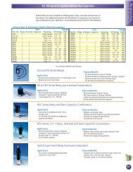
ContactorsCR353 (F&E) Series CoilSelection.Part Number Digit 10Denotes Coil VoltageCR353 Series50 to 90 Full Load Amps / 3 PoleFeatures• The standard CR353 contactors in the 50–90 FLA ratings are supplied with box lugterminals.• Power poles in the 50 – 90 FLA sizes aresupplied with two ¼” quick connectterminals.• Coils are provided with screw connectionswith a single ¼” quick connect terminal onthe 50 and 60 FLA size and two ¼” quickconnect terminals on the 75 and 90 FLAsize.PART NO. DIGIT H A B F C DCOIL VOLTAGE 60 Hz 24 110-120 208-240 277 460-480 440COIL VOLTAGE 50 Hz 24 110-120 208-240 *** 575-600 550FULL RESISTIVE LRA THREE PHASE 50/60 HzPART LOAD AMPS/ COILNO. AMPS POLE 240V 480V 600V VOLTAGECR353FE3BH1 50 62 300 250 200 24CR353FE3BA1 50 62 300 250 200 120CR353FE3BB1 50 62 300 250 200 208/240CR353FF3BH1 60 75 360 300 240 24CR353FF3BA1 60 75 360 300 240 120CR353FF3BB1 60 75 360 300 240 208/240CR353EG3BH1 75 90 450 375 300 24CR353EG3BA1 75 90 450 375 300 120CR353EG3BB1 75 90 450 375 300 208/240CR353EH3BH1 90 90 540 450 360 24CR353EH3BA1 90 90 540 450 360 120CR353EH3BB1 90 90 540 450 360 208/240Field Installed Auxiliary ContactsPART USE w/SUPCO FULLApplication NoteThe contactor is the primary controller in a coolingcontrols circuit. It is the switching device which activatesthe compressor motor to pump refrigerant through thesystem to provide cooling.Contactors are used to break the power supply to thecompressor. Either 1 or 2 poles are needed for singlephase; 2 or 3 poles for 3 phase motors. Auxiliarycontacts may be used for interlock switching, fan loadsor crankcase heaters. If the contactor is selected withan adequate current rating, the condenser fan may alsobe wired in parallel with the compressor. Then thecondenser fan is energized whenever the compressoris powered.Checking Contactor Operation:• Check contactor operation by switching thecontactor from the system controls.• Make sure that the pressure and overload controlscan break the system circuit to prevent contactoroperation, if necessary.• Check electrical conductance of the contacts.• Check the voltage source to the coil.8 8NO. CONTACTORS SERIES LOAD AMPS POLES DESCRIPTIONCR453XC211 CR453A 25-40 2-3 250V Side Mounted SPDTCR453XC222 CR453A 25-40 2-3 250V Side Mounted Two SPDTCR453XC611 CR453A 25-40 2-3 600V Side Mounted 1 NO - 1 NCCR453XM602 CR453A 25-40 2-3 600V Side Mounted 2 NOCR353XAAA CR353F 50-60 3 250V SPDTCR353XAAB CR353E 75-90 3 250V SPDT