
You also want an ePaper? Increase the reach of your titles
YUMPU automatically turns print PDFs into web optimized ePapers that Google loves.
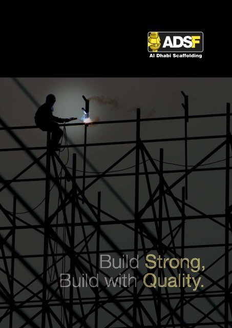
INTRODUCTION<strong>ADSF</strong> distinguishes itself from other scaffolding companies by offering completeturnkey scaffolding solutions. <strong>ADSF</strong> consists of three specialized divisions: rental,erection and manufacturing – which seamlessly work in conjunction with each otherto provide innovative, cost-effective and timely solutions to all your scaffoldingneeds.<strong>ADSF</strong> team produces the highest quality product for all form and false work solutions.With using the highest quality materials, <strong>ADSF</strong> delivers a product that canstand time after time the harsh environment of the construction world.
ADLOCK SUPPORT& DECKING SYSTEMOur ‘ADLock’ Support & Decking System is a multipurpose,safe and versatile scaffold system (erected with theleast number of moving parts) thus providing efficiency inspeed and savings on cost. The versatility of the deckingsystems enables it to provide a supporting grid for Beamand Trough as well as Flat & Hourdi slab construction.The Drop Head system allows early striking (3-4) dayswhich enables the Decking, Infill & the Plywood to beremoved leaving the support to the slab intact & in contactwith the concrete till the curing period.FAST EFFICIENT & SECURE ASSEMBLYWith this system, erection of support work is fast, efficient and secure due to thefact that there are no moving parts like nuts & bolts. The Ledger ends are placedon the bottom cups, the top cup turned in position and hammer tightened.ADLOCK SYSTEM COMPONENTS1. STANDARDSVertical element in 9 standard sizes with the horizontal element (Ledger) joint cups every 0.5m intervals.The top cups are castings made of high grade steel to allow the rigors of daily use.The bottom cups are high grade pressed steel.Length (mm)Weight (Kg)10005.3313006.6215007.1018008.7020009.30230011.60250012.04280015.003000 15.802. LEDGERSHorizontal element in 9 standard sizes with the locking element – the ledger end plate made of forged steel.Length (mm)Weight (Kg)6002.44800 3.089003.2610003.6612004.8013005.0016006.0418006.2425008.603. INTERMEDIATE TRANSOMLength (mm)10001200130018002500Weight (Kg)5.96.16.48.110.5
ADLOCK SUPPORT& DECKING SYSTEMBEAM BRACKETThis component used in conjunction with the Standard eliminates the use of Props in situations where the minimumdistance two support grids is greater than standard Ledger sizes. It also allows accommodation of Drop Beam supportwithin a supporting grid.4. SOCKET BASEA multi purpose component – combines with the Drop Head to make up the Drop Headassembly and also when bracing to the base is required it can be used in combination withthe Universal Jack to make up the base component.Height (mm)110Weight (Kg)1.45.‘U’ HEADUsed with the Universal Jack to take on Timber, Aluminium or Steel when these are usedas Primary Decking elements. It is also used as the base support when ‘Steel Soldiers’as used to span across voids in the base slab.Length (mm) Width (mm) Weight (Kg)150 170 2.9200 186 5.06. CANTILEVER FRAMEUsed when support on the base slab is not possiblespecially when drop beams around the perimeter of thebuildings needs to be supported and the earth aroundthe building is not levelled / compacted and in mostcases form the first floor onwards to either support thedrop beams or as access for the working personnel.Three hollow tubes at the edge allows slight adjustmentsfrom 1.2m to 1.3m and they come in 2 sizes – 1.0m & 1.5mLength (mm) Lift Height (mm) Weight (Kg)1625 1.0 15.52010 1.5 18.07. UNIVERSAL JACK & BASE JACKAllows adjustments in height at either the top or the bottom of the supportLength (mm) Effective Range (mm) Weight (Kg)760 520 3.98. BASE PLATEUsed when the combination of Base Jack, Standard,Universal Jack & Drop Head Assembly is not possible due to tricky heights.It also transfers the load from the Standard evenly.
ADLOCK SUPPORT& DECKING SYSTEMDECKING SYSTEMS9. DECKING BEAMThis main decking member is light weight due to the use of high grade steel.Heavy Duty pressings at the ends help it withstand rigors of daily site use.Slots at the ends take on the tongue of the Drop Head.Width of the top flange is 100mm. It comes in 3 standard sizes.Effective Length (mm) Flange Width (mm) Weight (Kg)1.2 100 12.51.8 100 18.12.5 100 28.210. DECKING BEAM SHOEAn element that allows usage of special lengths of timber as a deckingelement in conjunction with the Drop Head.11. INFILL BEAMThis secondary decking element is placed in between (at 90 deg. to) the maindecking members filling up the gaps to maintain allowable plywood spans.This component comes in 6 standard sizes.Actual Length (mm)Weight (Kg)500 4.0 (2.0mm thk.)800 4.8 (2.0mm thk.)900 5.0 (2.0mm thk.)1200 7.0 (2.0mm thk.)1500 9.0 (2.0mm thk.)1700 10.0 (2.0mm thk.)12. DROP HEADThis component enables the early striking of the system allowing theDecking & the Infill Beams along with the plywood to be removed for re-useon upper levels in 3 to 4 days of concrete pour. Before, during and afterthe early striking the top plate of the Drop Head maintains contact with theconcrete which can be left in position till the concrete is cured.Height (mm) Top Plate (mm) Weight (Kg)214 150 X 100 5.1TECHINICAL INFORMATION ON SLAB SUPPORTING GRIDSBay sizes – inversely proportional to the slab / beam thickness are showedin the following tabular form.Slab / Beam Thickness Bay SizeFrom To150mm 250mm 2.5m X 1.6m250mm 350mm 2.5m X 1.3m250mm 350mm 1.8m X 1.8m350mm 400mm 1.8m X 1.6m400mm 500mm 1.8m X 1.3m500mm 750mm 1.2m X 1.3m750mm 1000mm 1.2m X 1.0m1000mm 1750mm 1.2m X 0.6m
ADS QUIK STAGESYSTEM COMPONENTSEARLY STRIKINGADS QUIK STAGE SYSTEMA fast, economical and sturdy support system designed to enable quicksetting up and dismantling specially due to the lack of loose elements.The Drop Head allows Decking Beams on all four directions making thesystem more versatile to site conditions.ADS Quik Stage Support & Decking Layout1. STANDARDSA vertical support element, it is available in either ‘metric’ or ‘imperial’.It has ‘V’ pressings welded at every 495mm Intervals In 4 directionsat 90 degs to adjacent ‘V’ pressings. Load bearing capacities of theseStandards are 40kN & 55kN. Standards of a higher Load bearingcapacity of 75kN are available on special orders.Length (Feet)Weight (Kg)Length (mm)Weight (Kg)4’ 10 ½” Standard 8.0 kg6’6” Standard 11.5 kg9’9” Standard 17.5 kgHeavy Duty Standard 1000 mmHeavy Duty Standard 1500 mmHeavy Duty Standard 2000 mmHeavy Duty Standard 3000 mm5 kg8kg11.9 kg17.9 kg2. PROPPING TIESA horizontal support element, it has ‘C’ pressings designed to lockon to the ‘V’ pressings of the Standards.These are available in the following sizes:Length (mm)Weight (Kg)1200 mm 5.4 kg1800 mm 7.4 kg2400 mm 9.7 kg3. LEDGERSAnother horizontal support element, it has ‘J’ pressings at two endsdesigned to easily lock on to the ‘V’ pressings of the Standards.These are available in the following sizes:Length (Feet)Weight (Kg)2’8” Ledgers 3.5 kg4’2” Ledgers 5 kg6’ Ledgers 7.4 kg8’ Ledgers 9.3 kg
ADS QUIK STAGESYSTEM COMPONENTS4. SHORING TIESIt’s a horizontal support element designed with cast ‘C’ pressings to easily lock on to the ‘V’pressings of the Standards. It’s available in the following sizes:Length (mm)Weight (Kg)600 mm 4.2 kg900 mm 5.41 kg1200 mm 7.3 kg1800 mm 8.8 kg2400 mm 11.13 kg3000 mm 13.9 kg5. TRIGGER BRACESA diagonal bracing component, its designed with pins at both ends to easily lock onto the holes in the cast ‘C’ pressings of the Shoring Ties providing fast and sturdybracing. It’s available in the following sizes:Length (mm)Weight (Kg)2400 x 2000 mm 10.81 kg1800 x 2000 mm 9.43 kg1200 x 2000 mm 8.37 kg1800 x 1500 mm 8.27 kg1800 x 1000 mm 7.3 kg1200 x 1500 mm 7.0 kg1200 x 1000 mm 5.72 kg6. TRIGGER BRACE JACKUsed with the Top & Bottom adjustable Jacks and the Drop Head before final levelling.Range (mm)1900 to 2700 12.61100 to 1900 9.25800 to 1300 7.8Weight (Kg)7.SPIGOT ADAPTORIt’s used to connect two Standards vertically specially in higher soffit heights.8. TRANSOMSDesigned to fit into the ‘V’ pressings of the Standards, these inverted ‘T’section ional element comes in two different types, the ‘C’ pressing endsones and the ‘J’ pressing end ones. They are designed thus to accommodatethe Scaffold Boards.(a) ‘J’ Pressing Length (Feet) Weight (Kg)4’2” 7.22’8” 5.2(b) ‘C’ Pressing Length (mm) Weight (Kg)793 5.31250 7.41800 15.02400 20.0
ADS QUIK STAGESYSTEM COMPONENTS9. RETURN TRANSOMSTo avoid overlaps in right angle scaffolding extensions, these Transoms are used.‘J’ PressingLength (Feet)4’2” 10.02’8” 8.7Weight (Kg)‘C’ PressingLength (mm)1250 13.0793 8.0Weight (Kg)10. BEAM BRACKETAvailable in two standard sizes, 1.0 & 1.5m it’s used intight situations where support to the ground is not possible / desirable.11. CANTILEVER FRAMEAvailable in two standard sizes of 1.5m & 1.0m.It’s an element that continues the Decking / Infill tooutside the perimeter of the building for support to theSlab & Beams or as an Access platform for personnel access.12. CANTILEVER BEAM FRAMEAn Extension element normally used in the perimeter of the building speciallyas support to Drop Beams on higher floors were support legs cannot bebrought from the ground level. Available in two standard sizes of 1.5m & 1.0m13. HEAVY DUTY SPIGOT JACKAn adjustable Jack normally used under the Drop Headfor adjustments at the top made of high grade steel withrolled thread allowing adjustments to a maximum of 520mmwith a tubular lock welded towards the top end to lock the DropHead in position.14. TIE BARSThese are available in the following sizes:-Length (Feet)8’0” 7.26’0” 5.44’2” 3.82’8” 2.3Weight (Kg)15. DROP HEADA unique design whereby both Decking & Infill can be loaded onin all four directions. The dropping mechanicism allows the deckingand Infill along with the plywood to be removed for reuse withoutdisturbing the support work which can be left undisturbed till theconcrete is cured.
ADS QUIK STAGESYSTEM COMPONENTS16. DECKING BEAMSHeavy duty decking elements designed to allow one decking beamto sit on another at 90 degs. to each other making the Decking /Infill layout versatile. It’s available in the following sizes….17. INFILL BEAMSThis decking component is used in between the Decking Beams reducingthe gaps to allow plywood to span within allowable limits. It can also beloaded on to the Drop Head.ASSEMBLY OF <strong>ADSF</strong> QUIK STAGE DECKING ON THE SUPPORT SYSTEM1. Space out Base Jacks, Plane bases or Socket base/Spigot Jack assembly as per the Layout on the Shop Drawings provided.2. Fix a Standard on the Base Jack and two Propping Ties or Ledgers at the lowest ‘V’ pressings of the Standard at right anglesto each other as per the sizes specified in the drawing. Do not tighten.3. Attach another Standard adjacent to the first Standard and fix the Ledger/Propping Tie to the ‘V’ pressing repeat this witha third Standard and complete a right angled corner.4. Add another standard and two Ledgers/Propping Ties and complete a square/rectangle formation.5. Add another layer of Ledgers/Propping Ties on top of the previous one at intervals as shown on the provided Shop Drawing.Fix Spigot Jacks on top of the Standards to take on the Drop Heads and fix diagonal Bracings as per the Shop Drawingsprovided.6. Now add the Decking and Infill Beams to complete the Decking layout. Hammer tighten all the wedges on the ‘V’ pressings.7. Adjacent supporting grids can be fixed in a similar manner to complete the layout.DISMANTLING OF THE SYSTEMDismantling follows the whole process in reverse order whether the ‘Early Striking’ method is followed or not.15. EARLY STRIKINGDecking and Infill Beams can be removed before the concrete attains the required strength by striking the DropHead lock whereby the Decking / Infill plate on the Drop Head drops allowing easy removal of the Decking systemfor reuse to upper floors thus gaining concrete production by adding only one set of Supporting Components.<strong>ADSF</strong> QUIK STAGE AS HEAVY DUTY ACCESS SCAFFOLDINGMade up of mostly the same components as the Falsework counterpart, this system offers very strong access scaffolding tomeet stringent needs specially in load bearing terms. It’s also highly adaptable to difficult situations due to its versatility.
ADS QUIK STAGESYSTEM COMPONENTSADS QUIK STAGE SYSTEM COMPONENTS1. STANDARDSA vertical support element, it is available in either ‘metric’ or ‘imperial’.It has ‘V’ pressings welded at every 495mm Intervals In 4 directions at 90degs to adjacent ‘V’ pressings. Load bearing capacities of these Standardsare 40kN & 55kN. Standards of a higher Load bearing capacity of 75kN areavailable on special orders.2. GUARD RAIL LEDGERSThese Guard Rail are used as Ledgers connecting the Standards. These come in the following sizes:-Length (Feet)8’0” 11.36’0” 8.24’2” 5.82’8” 3.92’2” 3.7Weight (Kg)3. ADJUSTABLE HEAD & BASE JACKComprising of an inner & outer tube, the jack can be adjusted for height using the heavy duty pin onthe outer tube. Finer adjustments can be made utilizing the threaded collar.4. END TOE BOARD BRACKETUsed at the end of a scaffold run when a Toe Board is required.5. TOE BOARD BRACKETClamp and wedge connection for Toe Board to Standard
ADS QUIK STAGESYSTEM COMPONENTS6. SPIGOT & BASE JACKDescriptionUniversal Jack 5.3Base Jack 6.4Weight (Kg)7. DIAGONAL BRACESComponent with ‘C’ pressings fixed as a swivel on the sides of both endsallows quick & hassle free diagonal bracing on the Standards.Length (Feet)Weight (Kg)12’0” 13.89’0” 10.88. CANTILEVER PLATFORM BRACKETDesigned to fit into the ‘V’ pressings of the Standards, these inverted ‘T’ section ional element comes in three different sizes.They are designed to provide Scaffold Boards as cantilever access platform.Description3 Board Bracket 6.02 Board Bracket 5.41 Board Bracket 2.0Weight (Kg)9. STEEL BOARDIt is available in three different sizes:Length (Feet)8’0” 16.06’0” 12.24’0” 8.3Weight (Kg)10. STEEL SCAFFOLD BOARDScaffold Board designed with steel making it highly durable and providing sturdy access platforms. Load bearing of theseboards are 500 kg / bay. It comes in standard width of 225mm.
ADS HEAVY DUTYSOLDIER SYSTEM1. ADS HEAVY DUTY SOLDIER SYSTEMThe ADS Soldier is designed to be light weight but capable to handle immense loads. In applications with Aluminium Wailings,the system can be utilised to the optimum economies by increased spaces between the Soldiers thereby reducing the no ofties thus reducing the time required to erect / dismantle.• Deflections can be minimized even when faced with high concrete pressures.• Soldiers and Aluminium Wailing combination enhances productivity by reducing the no of vertical elements in the formworkresulting in less No. of ties. Can also be utilized for Non-Formwork applications.• Availability in different standard sizes optimizes adaptability.2. WALL FORMSADS Soldiers used in combination with Aluminium Walers, afford economical solutions to simple as well as complex concretestructures. It also provides high resistance to concrete pressures whereby deflections are kept to within allowable limits thussaving costs in repair works.This combination also allows ease in assembling and dismantling the formwork. The timber inserts in the Aluminium Walingsprovide easy fixing of the plywood.The versatility of the Soldier system, allows the Soldier to be used as Heavy Duty inclined Propping when used with Left& Right Jacks in instances were the pour height is substantial. It can also be used as Vertical Heavy Duty Propping for HeavyStructures.The 15mm Tie System with a SWL of 90kN optimises the full potential of the Soldier System.3. ADS HD SOLDIERSAvailable in eight standard sizes,Non-standard sizes can also be made to order.
ADS HEAVY DUTYSOLDIER SYSTEM4. TIMBER WALING CLAMPSA very user friendly fixture used to connect Soldiersto Timber when it is used as walings.5. UNIVERSAL CLAMPSA quick-fix fixture to connect the Soldiers to AluminiumWhalers by means of a ‘T’ Bolt & Nut.6. WEDGE CLAMPSAnother efficient connection between Soldier and Aluminium Walings, this clampassembly uses a tightening wedge instead of a Nut & Bolt assembly.7. LIFTING BRACKETSA Soldier top end assembly usually two Nos. per shutter allows secure lifting of theFormwork.8. SUPPORT PLATEA Soldier bottom end assembly usually used at every lifting points (Two Nos. / Shutter)to strengthen the Walings by attaching timber wedges between the Aluminium Walersand Support Plate. It is also used as support bases on uneven grounds.9. END TIE WASHERUsed when the Formwork needs to be stabilized these bottom end assembly is fixedto the ground by means of a Base plate and Strut.
ADS HEAVY DUTYSOLDIER SYSTEM10. STABILIZERA triangular anchoring assembly, normally used when the Formwork need tobe anchored securely.11. FORM JACKUsed as a bottom end assembly, it helps in levelling the Formwork as wellas acts as a plumbing device in Climbing Forms.SOLDIER ACCESSORIESHighly qualified personnel Design & Fabricate all special requirements for Formwork including Special Wallforms,Column Forms & Precast Moulds in our State-of-the-art facility.
ADS LIGHT WEIGHTSCAFFOLDING<strong>ADSF</strong> Light-weight access scaffold frames are manufactured with sturdy steel tubes with fixed spigot tubes and simple lockingdevices that make for rapid and easy connections between frames, horizontal ledgers and braces. All minor components are builtinto the frames thereby reducing the task of having to assemble and dismantle several components.It is essential to ensure that the light weight scaffolding is erected on a level area with frames located plumb and securely fastenedto the main structure while being. Couplers and scaffold tubes offer added security and stability to scaffolds over 20m high.Two types of Light Duty Frames are available – Italian Frame (Half-Ladder Frame) and the Korean Frame. It is manufactured usingsturdy steel tubes. There are no loose fittings providing Hassle-free Erection & Dismantling. The sturdy frames ensure safe personnel/ material access. Provided that the system is tied back to the building it can be utilised for plastering / painting / maintenancejobs in tall building structures.1. KOREAN FRAMENormally used for Interior, Exterior Painting, Plastering,Cabling, Ducting & Cleaning jobs.The dimensions are as follows: 1.7m High X 1.2m WideThe frames are placed 1.8m apart horizontally and crossbraces (2.2m) are fixed on both sides ensuring a Sturdyworking platform.
ADS LIGHT WEIGHTSCAFFOLDING2. ITALIAN FRAMEA very versatile access system, the Italian frame, made of 48mm steel tubes, provides economical solutions to a host ofaccess requirements. With no loose fittings they are simple to erect & dismantle.Dimensions as follows: 2.0m High X 1.0m WideThey are placed 3.0 / 2.75 / 2.5m apart horizontally and the cross braces along with a horizontal brace are fixed ensuring aSturdy working platform.It must be ensured that the base of the scaffold is level and that the frames are erected plumb. The system must be tied backto the building for safety & stability and in instances where the application is on buildings higher than 20m the base of thesystem need to be tied together.The Cross & Horizontal braces are made of27mm Dia. Tube and the length determinesthe bay sizes of 3.0, 2.75 or 2.5m.
ADS LIGHT DUTYMOBILE TOWER3. LIGHT WEIGHT MOBILE TOWERSMade of steel tubes with a load bearing capacity of 500 kgwhich includes the personnel & material weight. Combination ofthe base frame (2.0m X 2.0m) with castor wheels along with thestandard frame (2.0m X 1.0m) make up the Mobile tower.The standard frame allows two platform locations @ 0.5mintervals.Caution is advised as follows:• The castor wheel must always be locked for movement.• Guard post & rail are fixed at all times when the system is in use.• The platform boards bust have built in end hooks.• Never move the system with material / personnel.
ADS HEAVY DUTYMOBILE TOWER4. ADS HEAVY DUTY MOBILE TOWERStandard System (ADLock / ADS QUIK STAGE)accessories used in combination with Outriggersbuild the Heavy Duty Mobile Tower.Some of the salient features are:• Hassle-free erection & dismantling.• Economic, space saving storage.• Platform height range of 4m to 12m.• Variable bay / base sizes to meet specificrequirement.• A safe working height of 10m for externaluse and 12m for internal can be achived.5. ADS PROPSBuilt, confirming to British Standard BS 4074 : 1982 and tested toBS 5507 Part 3 : 1982, of high grade steel, these Props can be usedfor a multitude of purposes where an adjustable Load bearingelement is required.Coarse adjustments are possible utilising the heavy duty pin throughthe slot in the outer tube and the holes (@ regular intervals) in theinner tube. Finer adjustments are achieved through the rolled threadon the cast iron collar.
ADS FORMWORK / FALSEWORK ACCESSORIES6. HEAVY DUTY PROPMade of 3.2mm inner and 3.2mm outer tube they are available in five standard sizes offering extensions from 1.07m to 4.87mLenght (mm) Closed Open Weight3000 1750 3000 15.0 kg3500 2000 3500 16.8 kg4000 2500 4000 18.5 kg4500 3000 4500 20.0 kg7. MEDIUM DUTY PROPA 2.0mm Inner and 2.0mm Outer tube is used to make the Medium Duty Prop.Lenght (mm) Closed Open Weight3000 1750 3000 10.0 kg3500 2000 3500 12.0 kg4000 2500 4000 13.0 kg4500 3000 4500 14.0 kgCaution is advised as follows:• Props must always be loaded concentrically and be plumb.• SWLs allow not more than 1.5 Deg. Out-of-plumb loaded concentrically.• Any extension attachment bolted to the Prop must be considered in height when using the table.• It should be ensured that the Prop always rests on the safest axis and loaded concentrically.ADS TUBES & COUPLERS AND TIE SYSTEM1. ADS HEAVY DUTY TIE SYSTEMTwo types of Tie system make up the Heavy Duty Tie system. Removable, reusable and lost system. A protective tie cover(Plastic sleeve and plastic Cones) enables the reusable Tie system to be removed for re-use by preventing the Tie rods fromcontact with concrete.2. TIE RODAvailable in both 60kN and 90kN SWL versions, these generally are stocked and supplied in 6.0m lengths. Another optionavailable to the end user is the ‘All thread’ and the self cleaning ‘Intermittent thread’. Running the Wing Nut ensures that theTie rods are kept free of concrete / rust.3. WING NUTMade of malleable iron, it has a hexagonal head that facilitates use of a spanner to tighten it. The wings allow the nut to beeither hammer tightened or levered with a length of reinforcing bar. Available either in self colour or galvanised / electroplated.4. WALER PLATEAvailable in self colour (Black), painted or Galvanised / Electroplated, These come in the following sizes:-• 120 x 120 x 6mm• 150 x 150 x 8mm
ADS FORMWORK / FALSEWORK ACCESSORIES5. WATER STOPPERThis cast iron connector incorporates an impermeable core and flange. These are used when casting water-tight structureslike water tank walls were the use of through ties are not possible. This is a non-reusable item as it’s lost in the concreteafter pour.6. PLASTIC CONESThese recoverable cones are used at each end of the plastic conduit tube. This set the conduit tube 10mm short of the faceof the concrete wall / column. It also prevents the cohesion of the Plastic Tube to the plywood.7. PLASTIC TUBEThis rigid plastic tube is used to sheath the Tie Rod from the wet concrete allowing re-use of the Tie Rod after the concreteis set.8. COUPLERSAll fitting accessories confirm to BS/EN – 74 A-B.9. SLEEVE COUPLERUsed in joining two scaffold tube ends by wrapping around them. A central steel plate ensures that equal portions of both thetubes are held.10. PUTLOG COUPLERUsed to wrap around two vertical tubes without leaving a gap in between, these elements can also be utilized in connectingTransoms to Ledgers to support scaffold battens.11. SWIVEL COUPLERAs the name suggests, it’s a connector between two Scaffold Tubes connected at any angle. Removable ‘T’ bolt assemblyensures replacement in case of damage to the threads. Available either in Pressed or Drop-forged versions.12. DOUBLE COUPLERA right angle connector between Scaffold Tubes to Scaffold Tube or Scaffold Tube to Standard. Available in either Pressed orDrop Forged Versions.13. GRAVLOCK COUPLERA connector between Scaffold tubes to Slodier / Girder flange used in pairs.14. JOINT PINGenerally used in conjunction with Sleeve Coupler, the Joint Pin connects Two Tubes internally offering a secure connection.15. JACK NUTVertical Height adjustments are made possible with theuse of these nuts in either the Base or Universal jacks.Available in self colour, Galvanised or Electroplated.16. SCAFFOLD PALLETDesigned to stack long scaffolding accessories,it can be stacked one on top of the other saving spaceand enabling the stocking yard to be optimally utilized.