Operating Instructions (PDF) - Universal Minerals, Inc.
Operating Instructions (PDF) - Universal Minerals, Inc.
Operating Instructions (PDF) - Universal Minerals, Inc.

Create successful ePaper yourself
Turn your PDF publications into a flip-book with our unique Google optimized e-Paper software.
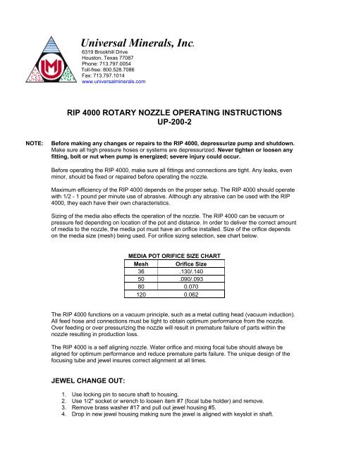
<strong>Universal</strong> <strong>Minerals</strong>, <strong>Inc</strong>.6319 Brookhill DriveHouston, Texas 77087Phone: 713.797.0054Toll-free: 800.528.7086Fax: 713.797.1014www.universalminerals.comRIP 4000 ROTARY NOZZLE OPERATING INSTRUCTIONSUP-200-2NOTE:Before making any changes or repairs to the RIP 4000, depressurize pump and shutdown.Make sure all high pressure hoses or systems are depressurized. Never tighten or loosen anyfitting, bolt or nut when pump is energized; severe injury could occur.Before operating the RIP 4000, make sure all fittings and connections are tight. Any leaks, evenminor, should be fixed or repaired before operating the nozzle.Maximum efficiency of the RIP 4000 depends on the proper setup. The RIP 4000 should operatewith 1/2 - 1 pound per minute use of abrasive. Although any abrasive can be used with the RIP4000, they each have their own characteristics.Sizing of the media also effects the operation of the nozzle. The RIP 4000 can be vacuum orpressure fed depending on location of the pot and distance. In order to deliver the correct amountof media to the nozzle, the media pot must have an orifice installed. Size of the orifice dependson the media size (mesh) being used. For orifice sizing selection, see chart below.MEDIA POT ORIFICE SIZE CHARTMesh Orifice Size36 .130/.14050 .090/.09380 0.070120 0.062The RIP 4000 functions on a vacuum principle, such as a metal cutting head (vacuum induction).All feed hose and connections must be tight to obtain optimum performance from the nozzle.Over feeding or over pressurizing the nozzle will result in premature failure of parts within thenozzle resulting in production loss.The RIP 4000 is a self aligning nozzle. Water orifice and mixing focal tube should always bealigned for optimum performance and reduce premature parts failure. The unique design of thefocusing tube and jewel insures correct alignment at all times.JEWEL CHANGE OUT:1. Use locking pin to secure shaft to housing.2. Use 1/2" socket or wrench to loosen item #7 (focal tube holder) and remove.3. Remove brass washer #17 and pull out jewel housing #5.4. Drop in new jewel housing making sure the jewel is aligned with keyslot in shaft.
5. Replace brass washer #17 and insert #7 focal tube housing into shaft and tighten to seatjewel. Seat jewel to 35-40 ft./lbs.6. We recommend pressurizing pump to desired pressure for approximately 10-15 secondsand retightening the focal tube holder before operating. Carbide focal tube can bereplaced by tapping on carbide from the front of housing forcing it out from the back.Insert new carbide and slightly tap to secure.SHAFT AND BEARING REMOVAL:Refer to Assembly and Parts List Sheet.For Proper Installation:1. Use locking pin to secure shaft and housing to remove #9 locking nut. Shaft can beremoved by pushing or tapping it from back to front of housing.2. Remove snap-rings #14 and #15.3. Next, remove washer and bearings. Please note that when replacing the bearing washers#12 and #13, always replace them correctly. Each washer has a slight counter bore onone side. Always put the counter bore side facing the bearing.4. Install bearing, outside washer and snap-rings.5. Install shaft from the front and tighten locking nut #9. Do not over tighten nut.Always use a stainless steel anti-galling lube such as <strong>Universal</strong> Mineral’s Yellow Lube UP-00003on all threads.TROUBLESHOOTING GUIDEPROBLEM POSSIBLE CAUSE SOLUTIONWater back-up in feed tube a. Jewel not seated a. Tighten focal tube nutb. Blown jewel b. Replace with new jewelNozzle Hsg, running hot Jewel not seated Tighten focal tube nutMedia flow slugging a. Wet material a. Use dry mediab. Wrong size orifice in pot b. For proper sizing, see MediaPot Orifice Size Chart aboveRotation slow when pressurized a. Air motor gyro-gun worn a. Repair gyro-gunb. Bad bearings b. Replace bearingsc. Over feeding bearings c. Lean out gritExcessive vibrationa. Worn bearings a. Replaceb. RIP brushing in gyro-gun b. Replacec wornShaft rotation tight after assembly a. Bent or warped washers a. Replaceb. Washers in backwards b. Put washers in correctly