Submarine Power Cables - Nexans
Submarine Power Cables - Nexans
Submarine Power Cables - Nexans
- No tags were found...

You also want an ePaper? Increase the reach of your titles
YUMPU automatically turns print PDFs into web optimized ePapers that Google loves.
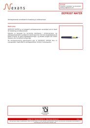
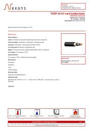
Medium-voltage submarine cable, XLPE insulatedTypical design of a medium-voltagesubmarine cable with a maximumvoltage up to 36 kVType: (F)2XS2Y>c
(F)2XS(FL)2Y>cccc
Cable Data XLPELegend for tablesConstructional Data1, 2, 3, 4, 5, – Nominal values6, 7, 89, 10, 11 – Approx. valuesElectrical Data1 – Nominal value2 – Max. value to IEC 602283, 4, 5, 6, 9 – Approx. values7 – Calculated in accordance to IEC publications 60287and the following assumptions– Max. conductor temperature at continuous load 90 °C– Frequency 50 Hz– Max. ambient temperature 20 °C– Screens bonded at both ends and connected to earth– burrial depth of cables 1.0 m– Thermal resistivity of surroundings 1.0 K · m/W8 – at current acc. to 7Constructional Data, Electrical DataA2XS(FL)2Y>cc
A2XS(FL)2Y>cccc
Cable Data XLPELegend for tablesConstructional Data1, 2, 3, 4, 5, – Nominal values6, 7, 89, 10, 11 – Approx. valuesElectrical Data1 – Nominal value2 – Max. value to IEC 602283, 4, 5, 6, 9 – Approx. values7 – Calculated in accordance to IEC publications 60287and the following assumptions– Max. conductor temperature at continuous load 90 °C– Frequency 50 Hz– Max. ambient temperature 20 °C– Screens bonded at both ends and connected to earth– burrial depth of cables 1.0 m– Thermal resistivity of surroundings 1.0 K · m/W8 – at current acc. to 7Constructional Data, Electrical Data(F)2XS2Y>cc
(F)2XS2Y>cccc
Cable Data EPRLegend for tablesConstructional Data1, 2, 3, 4, 5, 6 – Nominal values7, 8, 9 – Approx. valuesElectrical Data1 – Nominal value2 – Max. value to IEC 602283, 4, 5, 6, 9 – Approx. values7 – Calculated in accordance to IEC publications 60287and the following assumptions– Max. conductor temperature at continuous load 90 °C– Frequency 50 Hz– Max. ambient temperature 20 °C– Screens bonded at both ends and connected to earth– burrial depth of cables 1.0 m– Thermal resistivity of surroundings 1.0 K · m/W8 – at current acc. to 7Constructional Data, Electrical Data(F)3GSERAA 6/10(12) kVConstructional Data1 2 3 4 5 6 7 8 9Nominal cross Conductor Insulation Screen Bedding Armour Serving Outer <strong>Cables</strong>ectional area copper round EPR copper tapes wall thickness steel wires bitumen diameter weightof conductor stranded wall thickness cross round fib. material of cablediameter over sectional area galvanized incl. colour stripconductor diameter wall thickness(mm 2 ) (mm) (mm) (mm 2 ) (mm) (mm) (mm) (mm) (t/km)35 7.0 3.4 3x4 2 4.0 3.5 56 5.450 8.2 3.4 3x4 2 4.0 3.5 58 6.070 9.9 3.4 3x5.4 2 4.0 3.5 64 7.395 11.5 3.4 3x5.4 2 4.0 3.5 68 8.5120 13.0 3.4 3x5.4 2 4.0 3.5 71 9.5150 14.5 3.4 3x6 2 4.0 3.5 74 10.7185 16.1 3.4 3x6 2 4.0 3.5 78 12.2240 18.6 3.4 3x6 2 4.0 3.5 83 14.3(F)3GSERAA 6/10(12) kVElectrical Data1 2 3 4 5 6 7 8 9Nominal cross Conductor Conductor Screen Capacitance Inductance Current rating Losses 1s short circuit currentsectional area resistance resistance resistance after full load at 90 °CDC 20 °C AC 90 °C 20 °C conductor temperatureconductor screen conductor screen(mm 2 ) (mm 2 ) (Ω/km) (Ω/km) (Ω/km) (µF/km) (mH/km) (A) (W/m) (kA) (kA)35 3x4 0.524 0.67 1.83 0.28 0.36 165 55 5.0 2.250 3x4 0.387 0.49 1.83 0.31 0.34 195 58 7.1 2.270 3x5.4 0.268 0.34 1.15 0.39 0.34 239 61 10.0 2.995 3x5.4 0.193 0.25 1.15 0.43 0.32 286 63 13.6 2.9120 3x5.4 0.153 0.20 1.15 0.46 0.31 325 65 17.1 2.9150 3x6 0.124 0.16 1.05 0.50 0.30 364 67 21.4 3.3185 3x6 0.0991 0.13 1.05 0.54 0.29 410 69 26.5 3.3240 3x6 0.0754 0.099 1.05 0.61 0.28 472 73 34.3 3.312
(F)3GSERAA 12/20(24) kVConstructional Data1 2 3 4 5 6 7 8 9Nominal cross Conductor Insulation Screen Bedding Armour Serving Outer <strong>Cables</strong>ectional area copper round EPR copper tapes wall thickness steel wires bitumen diameter weightof conductor stranded wall thickness cross round fib. material of cablediameter over sectional area galvanized incl. colour stripconductor diameter wall thickness(mm 2 ) (mm) (mm) (mm 2 ) (mm) (mm) (mm) (mm) (t/km)35 7.0 5.5 3x5.4 2 4.0 3.5 64 6.650 8.2 5.5 3x5.4 2 4.0 3.5 67 7.470 9.9 5.5 3x6 2 4.0 3.5 73 8.795 11.5 5.5 3x6 2 4.0 3.5 76 9.9120 13.0 5.5 3x6 2 4.0 3.5 80 11.1150 14.5 5.5 3x6 2 4.0 3.5 83 12.3185 16.1 5.5 3x6 2 4.0 3.5 86 13.8240 18.6 5.5 3x10 2 4.0 3.5 92 16.0(F)3GSERAA 12/20(24) kVElectrical Data1 2 3 4 5 6 7 8 9Nominal cross Conductor Conductor Screen Capacitance Inductance Current rating Losses 1s short circuit currentsectional area resistance resistance resistance after full load at 90 °CDC 20 °C AC 90 °C 20 °C conductor temperatureconductor screen conductor screen(mm 2 ) (mm 2 ) (Ω/km) (Ω/km) (Ω/km) (µF/km) (mH/km) (A) (W/m) (kA) (kA)35 3x5.4 0.524 0.67 1.05 0.20 0.41 165 56 5.0 2.950 3x5.4 0.387 0.49 1.05 0.22 0.39 191 56 7.1 2.970 3x6 0.268 0.34 1.05 0.27 0.37 239 61 10.0 3.395 3x6 0.193 0.25 1.05 0.29 0.35 286 64 13.6 3.3120 3x6 0.153 0.20 1.05 0.32 0.34 322 65 17.1 3.3150 3x6 0.124 0.16 1.05 0.34 0.33 363 68 21.4 3.3185 3x6 0.0991 0.13 1.05 0.37 0.32 408 70 26.5 3.3240 3x10 0.0754 0.098 0.63 0.41 0.31 470 74 34.3 5.4(F)3GSERAA 18/30(36) kVConstructional Data1 2 3 4 5 6 7 8 9Nominal cross Conductor Insulation Screen Bedding Armour Serving Outer <strong>Cables</strong>ectional area copper round EPR copper tapes wall thickness steel wires bitumen diameter weightof conductor stranded wall thickness cross round fib. material of cablediameter over sectional area galvanized incl. colour stripconductor diameter wall thickness(mm 2 ) (mm) (mm) (mm 2 ) (mm) (mm) (mm) (mm) (t/km)50 8.2 8.0 3x6 2 4.0 3.5 77 9.170 9.9 8.0 3x6 2 4.0 3.5 83 10.695 11.5 8.0 3x6 2 4.0 3.5 86 11.8120 13.0 8.0 3x6 2 4.0 3.5 89 13.0150 14.5 8.0 3x10 2 4.0 3.5 93 14.3185 16.1 8.0 3x10 2 4.0 3.5 96 15.8240 18.6 8.0 3x10 2 4.0 3.5 102 18.2(F)3GSERAA 18/30(36) kVElectrical Data1 2 3 4 5 6 7 8 9Nominal cross Conductor Conductor Screen Capacitance Inductance Current rating Losses 1s short circuit currentsectional area resistance resistance resistance after full load at 90 °CDC 20 °C AC 90 °C 20 °C conductor temperatureconductor screen conductor screen(mm 2 ) (mm 2 ) (Ω/km) (Ω/km) (Ω/km) (µF/km) (mH/km) (A) (W/m) (kA) (kA)50 3x6 0.387 0.49 1.05 0.17 0.42 195 58 7.1 3.370 3x6 0.268 0.34 1.05 0.21 0.41 238 62 10.0 3.395 3x6 0.193 0.25 1.05 0.22 0.39 285 64 13.6 3.3120 3x6 0.153 0.20 1.05 0.24 0.37 323 66 17.1 3.3150 3x10 0.124 0.16 0.63 0.26 0.36 361 68 21.4 5.4185 3x10 0.0991 0.13 0.63 0.28 0.35 406 71 26.5 5.4240 3x10 0.0754 0.098 0.63 0.30 0.33 467 74 34.3 5.413
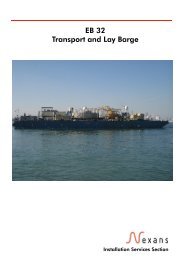
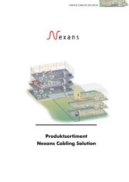
ApplicationsOffshore windfarmOffshore production platform in Indonesia,with power supply through a submarine cable34.5 kV shore substation submarine cable project Mindanao, PhilippinesLanding a submarine cable at shore of an Australien Island14
Accessories and ServicesAccessoriesAccessories – from cable hang-offs viasealing ends for the connection to theswitchgears up to the splice boxes for opticalfibre cables – enable comprehensivesolutions for cabling systems. They offerplanners and operators a wide varietyof standardized components for a highdegree of flexibility.ServiceHighspecialized <strong>Nexans</strong> employees,trained for offshore jobs, carry out the demandingtasks on site – from the connectionto switchgears, the splicing of opticalfibre cables for data communication, upto the commissioning tests which successfullyconclude the installation work.Project management<strong>Nexans</strong> project management teamsare looking after the submarine cableprojects. The project manager or projectteam in charge plans and supervisesindividual operational sequences andcoordinates processes – until the successfulconclusion of the project.EngineeringThe development of new products, processesand systems in close collaborationwith the customer is the concept behindthe success of <strong>Nexans</strong>. The fact thatproduction, project management, salesand engineering are all located at thesame premises, is an advantage turnedto good account at our Hanover location.This way, the individual technically andeconomically optimized system solutionsare developed to guarantee the safeoperation of offshore wind park facilitiesand other applications.Environment managementKeeping ecological concerns for the protectionof resources in mind, economicaladvantages can be achieved. A constantreduction of raw materials and energyconsumption as well as the consistentimprovement of our products, processesand technologies in ecological terms ispart of our environmental policy.15
<strong>Nexans</strong> welcomes your inquiries. For elaboration of a proposal most suitable for your individual requirements, detailed informationsshould be given to the following questions (as far as applicable):1. ApplicationAttach plan of layout, if possible................................................................................................................................2. Transmitted voltageRated system voltage (U O/U).....................................................................................................................................Highest continuous voltage (U m).................................................................................................................................Operating frequency...............................................................................................................................................3. Transmitted powerRated transmitted power (kVA)...................................................................................................................................Short circuit current (kA)............................................................................................................................................Short circuit duration (s)............................................................................................................................................4. Type of operationPublic network (load cycling).....................................................................................................................................Continuous full load operation...................................................................................................................................Requirements for control/telecommunication circuits.......................................................................................................5. Grounding conditions ............................................................................................................................................6. Conditions of cable routeLength of cable route (route plan)...............................................................................................................................Water depth..........................................................................................................................................................Water flow conditions/tide.......................................................................................................................................Thermal resistance of the soil.....................................................................................................................................Laying depth..........................................................................................................................................................Soil temperature......................................................................................................................................................Conditions of the cable route at the beginning and at the end.........................................................................................Cable laying in pipes or in the air..............................................................................................................................Ambient temperature................................................................................................................................................On-shore cable protection requirements.......................................................................................................................7. Transport and laying conditionsRequired laying method (laying on bottom, water jet trenching)........................................................................................Will laying be performed by customer or seperate subcontractor......................................................................................Are there limitations for handling sizes and weights.......................................................................................................Are cable laying barges available.............................................................................................................................Load carrying capacity of the laying barge..................................................................................................................Dimensions of the loading platform.............................................................................................................................16
For your notes17
For your notes18
For your notes19
Global experts in cables and cabling systems<strong>Nexans</strong> Deutschland GmbHKabelkamp 20 · 30179 HannoverTel.: +49 511 676-1 · Fax: +49 511 676-2444 · www.nexans.deJune 2013 - Copyright © 2013 - <strong>Nexans</strong> - (0613.010.08) - (844 12 002)