HP Integrity rx7640 Server
HP Integrity rx7640 Server
HP Integrity rx7640 Server
You also want an ePaper? Increase the reach of your titles
YUMPU automatically turns print PDFs into web optimized ePapers that Google loves.
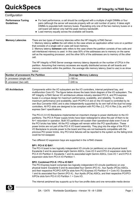
QuickSpecs<strong>HP</strong> <strong>Integrity</strong> <strong>rx7640</strong> <strong>Server</strong>ConfigurationPerformance TuningGuidelinesFor best performance, a cell should be configured with a multiple of eight DIMMs or fourpairs (although the server will execute properly with an odd number of pairs). It takes eightDIMMs to populate both memory buses. Populating only one of the two memory buses on acell board will deliver only half the peak memory bandwidth.Load memory equally across the available cell boards.Memory LatenciesThere are two types of memory latencies within the <strong>HP</strong> <strong>Integrity</strong> <strong>rx7640</strong> <strong>Server</strong>:1. Memory latency within the cell refers to the case where an application either runs on a partitionthat consists of a single cell or uses cell local memory.2. Memory latency between cells refers to the case where the partition consists of two cells andcell interleaved memory is used. In this case 50% of the addresses are to memory on the samecell as the requesting processor, and the other 50% of the addresses are to memory of the othercell.Number of processors Per PartitionThe <strong>HP</strong> <strong>Integrity</strong> <strong>rx7640</strong> <strong>Server</strong> average memory latency depends on the number of CPUs in thepartition. Assuming that memory accesses are equally distributed across all cell boards andmemory controllers within the partition, the average idle memory latency (load to use) is as showbelow:4- processor (single cell) ~185 ns8- processor (two cell) ~249 nsAverage Memory LatencyI/O ArchitectureComponents within the I/O subsystem are the I/O controllers, internal peripheral bay, andmultifunction Core I/O. The figure below shows the basic block diagram of the I/O subsystem. The<strong>HP</strong> <strong>Integrity</strong> <strong>rx7640</strong> <strong>Server</strong> I/O architecture utilizes industry standard PCI X, and PCI-expressbuses in a unique design for maximum performance, scalability, and reliability. To achievemaximum performance and availability, each PCI/PCI-X slot on the I/O board is controlled by itsown Bus Converter ASIC and is also independently supported by its own half of the dual hot swapcontrollers. All PCI slots are designed to be compliant with PCI Rev.2.2, PCI-X Rev.2.0a, and PCIexpressGen1 specifications.The PCI-X 2.0 I/O Backplane implemented an important change to power distribution to the I/Opartitions. The PCI-X Power supply bricks have been redesigned to allow the pair of them to beN+1 redundant in operation. Both I/O partitions will sustain their operational state even if one ofthe PCI bricks has failed. All the PCI voltages will remain within the PCI specification. Thesepower bricks are not part of the PCI-X I/O board assembly. They plug into the edge of the PCI-XI/O Backplane to provide power to the board and they are not backwards compatible with theprevious PCI power bricks. Any PCI brick failures will be reported to the system so the failing brickcould be hot swapped.Two different IO expansion bays are supported in the <strong>rx7640</strong> chassis:BP1: PCI-X IO BAY:The PCI-X board is two logically independent I/O circuits (or partitions) on one physical board:Escalante 0 and its associated eight Gemini ASICs, Core I/O 0 and 8 PCI-X expansion slots formPCI-X I/O Partition 0. Escalante 1 and its associated eight Gemini ASICs, Core I/O 1 and 8 PCI-Xexpansion slots form PCI-X I/O Partition 1.BP2: Combined PCI-X / PCI-e IO BAY:The PCI-Express board comprises two logically independent I/O circuits (partitions) on onephysical board: Escalante 0 and its associated four Gemini (PCI-X) , four Apollo (PCIe) ASICs,and their respective PCI/PCI-X/PCIe slots form PCI-Express I/O Partition 0 + Core I/O. Escalante1 and its associated four Gemini (PCI-X) , four Apollo (PCIe) ASICs, and their respective PCI/PCI-X/PCIe slots form PCI-X I/O Partition 1 + Core I/O.The internal peripheral bay supports up to four low profile disks and one removable media deviceDA - 12470 Worldwide QuickSpecs — Version 19 — 8-1-2008 Page 8


