BEsT MANAGEMENT PRACTICEs HANDbooK - Tahoe BMP
BEsT MANAGEMENT PRACTICEs HANDbooK - Tahoe BMP
BEsT MANAGEMENT PRACTICEs HANDbooK - Tahoe BMP

You also want an ePaper? Increase the reach of your titles
YUMPU automatically turns print PDFs into web optimized ePapers that Google loves.
PREFACEThe <strong>Tahoe</strong> Regional Planning Agency (TRPA) Best Management Practices(<strong>BMP</strong>) Handbook provides technical and planning guidance to landowners,private businesses, agencies, and jurisdictions for water quality improvementprojects. The Handbook is offered to help meet the standards set forth in theTRPA Code of Ordinances and for reducing pollutants of concern identified inthe Lake <strong>Tahoe</strong> Total Maximum Daily Loads (TMDL) as set forth by theNevada Division of Environmental Protection and the Lahontan RegionalWater Quality Control Board.This Handbook should be used as a general guidance document to aid with siteanalysis, <strong>BMP</strong> design, and long-term maintenance of stormwater qualitycontrol measures. Because not all of the control practices noted in thisHandbook are necessary or even appropriate for all sites, individual siteconditions must be considered when projects are designed. TRPA makes noclaims that this <strong>BMP</strong> Handbook is all inclusive. On the contrary, there are<strong>BMP</strong> technologies that, while not currently a part of this <strong>BMP</strong> Handbook, canbe effectively designed and employed in the Lake <strong>Tahoe</strong> Region to fulfillenvironmental regulations.<strong>BMP</strong> HANDBOOK REVISIONSThis revised 2012 <strong>BMP</strong> Handbook updates and replaces the existing 1988Handbook of Best Management Practices, which previously served as VolumeII of the 1988 Water Quality Management Plan for the Lake <strong>Tahoe</strong> Region(208 Plan).At Lake <strong>Tahoe</strong>, TMDLs have been developed through a collaborative effortbetween TRPA, the U.S. Environmental Protection Agency, the States ofCalifornia and Nevada, other regulatory agencies, the science community, andlocal jurisdictions. The revised <strong>BMP</strong> Handbook incorporates relevantinformation from the Lake <strong>Tahoe</strong> TMDLs related to reducing Lake <strong>Tahoe</strong>’spollutants of concern (namely, fine sediments, phosphorus, and nitrogen).The science, research, and technology of stormwater quality management areevolving and new innovative control measure technologies are regularly beingintroduced and revised. Therefore, the TRPA <strong>BMP</strong> Handbook will bereviewed and updated periodically as new information becomes available withregards to <strong>BMP</strong> design, installation, effectiveness, and maintenance.. Users ofthis <strong>BMP</strong> Handbook are responsible for ensuring that they are referencing themost current edition by checking tahoebmp.org, trpa.org, or by contacting the<strong>Tahoe</strong> Regional Planning Agency.TRPA <strong>BMP</strong> HandbookPreface2012 Page i
DISCLAIMERTRPA and the contributing agencies do not claim any responsibility for anyloss, damage, or injury resulting from the use of this Handbook, includingerrors or omissions that might contribute to non-performance or failure of thestormwater quality control measures. Many of the <strong>BMP</strong>s described in this <strong>BMP</strong>Handbook must be designed by, or under the supervision of, a licensedprofessional civil or hydrological engineer and/or other specialists, dependingon the type of control measure and site conditions. <strong>BMP</strong>s and theirmaintenance are ultimately the responsibility of the landowner.PrefaceTRPA <strong>BMP</strong> HandbookPage ii 2012
TABLE OF CONTENTSPREFACE....................................................................................................................................................................... iINTRODUCTION ....................................................................................................................................................................1CHAPTER 1: URBAN HYDROLOGY .......................................................................................................................... 1-11.1 Purpose and Use of Chapter ............................................................................................................ 1-11.2 Overview of Hydrologic Analysis .................................................................................................. 1-21.2.1 Hydrology Processes ........................................................................................................................ 1-21.2.2 Impervious Coverage and <strong>BMP</strong> Implementation ................................................................. 1-41.2.3 Pollutant Loads ................................................................................................................................... 1-51.2.4 Hydrologic Data and Modeling ................................................................................................... 1-61.3 Summary of Selected Methods ..................................................................................................... 1-81.3.1 Project Categories – Defining Scale and Complexity ........................................................ 1-81.3.1.1 Projects Less than 1 Acre and all Single Family Residential (SFR) .......... 1-81.3.1.2 Projects 1 to 5 Acres and all Commercial (CICU)............................................. 1-91.3.1.3 Projects Greater than 5 Acres ............................................................................... 1-101.3.2 Key to Hydrologic and StormWater Quality Analysis Methods ................................ 1-101.3.3 Summary Sheets ............................................................................................................................. 1-111.3.3.1 Template and Typical Content .............................................................................. 1-141.3.3.2 NRCS <strong>BMP</strong> Calculation Spreadsheet ................................................................... 1-151.3.3.3 Rational Method ......................................................................................................... 1-171.3.3.4 Load Reduction Planning Tool (LRPT)................................................................ 1-191.3.3.5 Hydrologic Modeling System (HMS).................................................................. 1-201.3.3.6 Pollutant Load Reduction Model (PLRM)......................................................... 1-231.3.3.7 HSPF and LSPC ............................................................................................................. 1-251.3.3.8 Storm Water Management Model (SWMM).................................................. 1-271.4 Available Information – Lake <strong>Tahoe</strong> Region Hydrology ................................................... 1-291.4.1 TMDL Development and Modeling ........................................................................................ 1-291.4.2 Soils, Land Use, and Hydrometeorology ............................................................................... 1-30CHAPTER 2: SITE ANALYSIS ....................................................................................................................................... 2-12.1 Purpose and Use of This Chapter .................................................................................................. 2-12.2 Projects Less Than 1 Acre and All Single Family Residential Projects ......................... 2-22.2.1 Initial Data Gathering ....................................................................................................................... 2-22.2.1.1 Land Use ............................................................................................................................ 2-22.2.1.2 Project Area Base Map ................................................................................................ 2-22.2.1.3 Parcel Boundaries .......................................................................................................... 2-22.2.1.4 Topographic Information ............................................................................................ 2-22.2.1.5 NRCS Soil Survey ........................................................................................................... 2-22.2.1.6 Utilities ................................................................................................................................ 2-52.2.2 Initial Site Visit .................................................................................................................................... 2-52.2.2.1 Existing Site Conditions and Uses On-site .......................................................... 2-52.2.2.2 Complex On-site Hydrology ................................................................................... 2-11TRPA <strong>BMP</strong> HandbookTable of Contents2012 Page i
2.2.2.3 Site limitations and Constraints ........................................................................... 2-132.2.3 Additional Data Gathering .......................................................................................................... 2-142.3 Projects 1 to 5 Acres and All Commercial Industrial Communications Utilities Sites(CICU) ....................................................................................................................................................... 2-172.3.1 Initial Data Gathering .................................................................................................................... 2-172.3.1.1 Land Use ......................................................................................................................... 2-172.3.1.2 Project Area Base Map ............................................................................................. 2-172.3.1.3 Parcel and Property Boundaries ........................................................................... 2-172.3.1.4 Topography Information .......................................................................................... 2-172.3.1.5 Precipitation Information ........................................................................................ 2-182.3.1.6 NRCS Soil Survey ........................................................................................................ 2-182.3.1.7 Land Capability Classification and Allowable Land Coverage ................ 2-202.3.1.8 Utilities ............................................................................................................................. 2-212.3.2 Initial Site Visit ................................................................................................................................. 2-212.3.2.1 Existing Site Conditions and Uses On-site ....................................................... 2-222.3.2.2 Complex On-site Hydrology ................................................................................... 2-262.3.2.3 Site Constrained Properties .................................................................................... 2-292.3.3 Additional Data Gathering for Design or Follow-Up Site Visits ................................. 2-292.3.3.1 On-site Constant Head Permeameter (CHP) or Percolation Test ........... 2-292.3.3.2 Soils Hydrologic report ............................................................................................. 2-302.3.3.3 Piezometer ..................................................................................................................... 2-302.3.3.4 Land Capability Verification/Land Coverage Verification .......................... 2-302.3.3.5 Topographic Survey ................................................................................................... 2-312.3.3.6 On-site Utility Verification ....................................................................................... 2-312.4 Projects Greater Than 5 Acres ...................................................................................................... 2-31CHAPTER 3: PERMANENT <strong>BMP</strong> PLANNING AND SELECTION ...................................................................... 3-13.1 Purpose and Organization of this Chapter ................................................................................ 3-13.2 Relationship of <strong>BMP</strong> Plan Development to Preferred Design Approach (PDA)...... 3-23.3 Project Scale and Complexity ......................................................................................................... 3-33.4 Projects Less Than 1 Acre and All Single Family Residential Projects ......................... 3-33.4.1 Standards and Regulations ............................................................................................................ 3-43.4.2 Pollutant Source Control ................................................................................................................ 3-43.4.2.1 Waste Management and Materials Pollution Prevention ........................... 3-53.4.2.2 Soil Stabilization ............................................................................................................. 3-53.4.3 Hydrologic Source Control ............................................................................................................. 3-73.4.4 Stormwater Collection and Conveyance................................................................................. 3-93.4.5 Stormwater Treatment ................................................................................................................. 3-103.5 Projects 1 to 5 Acres and All Commercial, Industrial, Communications and Utilities(CICU) Projects < 5 Acres ................................................................................................................. 3-113.5.1 Standards and Regulations ......................................................................................................... 3-143.5.2 Pollutant Source Control ............................................................................................................. 3-143.5.2.1 Waste Management and Materials Pollution Prevention ........................ 3-143.5.2.2 Roadway and Parking Lot Pollution Prevention ........................................... 3-173.5.2.3 Soil Stabilization .......................................................................................................... 3-193.5.3 Hydrologic Source Control .......................................................................................................... 3-213.5.4 Stormwater Collection and Conveyance.............................................................................. 3-23Table of ContentsTRPA <strong>BMP</strong> HandbookPage ii 2012
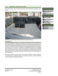
3.5.5 Stormwater Treatment ................................................................................................................. 3-253.5.5.1 Meet Discharge Standards ..................................................................................... 3-253.5.5.2 PreTreat Stormwater Runoff Prior to Infiltration ......................................... 3-253.6 Projects Greater Than 5 Acres and WQIPs ............................................................................. 3-263.6.1 Standards and Regulations ......................................................................................................... 3-263.6.1.1 Jurisdiction ..................................................................................................................... 3-273.6.1.2 Private Projects ............................................................................................................ 3-283.7 Inspection, Maintenance, and Monitoring .............................................................................. 3-283.8 Site Constraints and Limitations ................................................................................................. 3-293.8.1 Special circumstances if infiltration is not feasible ......................................................... 3-293.8.2 Common Site Constraints and Associated <strong>BMP</strong> Design Concepts ........................... 3-293.8.2.1 High Groundwater and Bedrock .......................................................................... 3-303.8.2.2 Utilities and Infrastructure ...................................................................................... 3-303.8.2.3 Run-On from Off-Site Upstream Locations ...................................................... 3-303.8.2.4 Shared Access and Easements, and Impervious Areas over MultipleParcel Ownerships ..................................................................................................... 3-313.8.2.5 Retaining Walls along Driveways and Roads ................................................ 3-313.8.2.6 Proximity to Drinking Water Wells ..................................................................... 3-313.8.2.7 100 Percent Imperviousness .................................................................................. 3-323.8.2.8 Stream Environment Zones (SEZs) ...................................................................... 3-333.9 Special Land Use Considerations ................................................................................................ 3-333.9.1 Scenic Highway Corridors ........................................................................................................... 3-333.9.2 Lakefront and Shorezone ............................................................................................................ 3-333.9.3 Wildland Urban Interface............................................................................................................. 3-333.9.4 Forest Service Summer Seasonal Use Only Designation .............................................. 3-343.9.5 Conservation and Recreation Areas ....................................................................................... 3-343.10 Temporary Construction <strong>BMP</strong>s ................................................................................................... 3-343.11 Agency <strong>BMP</strong> Inspections ............................................................................................................... 3-35CHAPTER 4: <strong>BMP</strong> TOOLKIT .............................................................................................................................................14.1 Hydrologic Source Control ................................................................................................................... 14.1.1.1 Pervious Pavement ........................................................................................................... 14.1.1.2 Infiltration Basin ................................................................................................................. 14.1.1.3 Infiltration Trench .............................................................................................................. 14.1.1.4 SubSurface Infiltration System .................................................................................... 14.1.1.5 Rain Barrel and Cistern .................................................................................................... 14.1.1.6 Rain Garden .......................................................................................................................... 14.1.1.7 Filter Strip .............................................................................................................................. 14.2 Pollutant Source Control ...................................................................................................................... 14.2.1 Roadway and Parking Lot Pollutant Prevention ...................................................................... 14.2.1.1 Abrasive and Deicer Management ............................................................................ 14.2.1.2 Street Sweeping ................................................................................................................. 14.2.1.3 Snow Storage ...................................................................................................................... 14.2.2 Slope Stabilization ................................................................................................................................. 14.2.2.1 Vegetated Slope Stabilization ...................................................................................... 14.2.2.2 Terracing ................................................................................................................................ 14.2.2.3 Retaining Wall ..................................................................................................................... 1TRPA <strong>BMP</strong> HandbookTable of Contents2012 Page iii
4.5.1.7 Dust Control ......................................................................................................................... 14.5.1.8 Vehicle Ingress Egress Management ........................................................................ 14.5.1.9 Winterization ....................................................................................................................... 14.5.1.10 Construction Staging ........................................................................................................ 14.5.1.11 Material Handling Storage and Safety ..................................................................... 14.5.1.12 Topsoil Salvage ................................................................................................................... 14.5.1.13 Concrete/Bentonite Management .............................................................................. 14.5.1.14 Stockpile Management ................................................................................................... 14.5.2 Erosion and Sediment Control ......................................................................................................... 14.5.2.1 Sweeping .............................................................................................................................. 14.5.2.2 Drain Inlet Protection....................................................................................................... 14.5.2.3 Fiber Roll ................................................................................................................................ 14.5.2.4 Silt Fence ............................................................................................................................... 14.5.2.5 Erosion Control Blanket System .................................................................................. 14.5.2.6 Hydromulch, Tackifier, and Soil Binder ..................................................................... 1CHAPTER 5: SOIL AND VEGETATION <strong>MANAGEMENT</strong> ..................................................................................... 5-15.1 Purpose and Use of this Chapter ................................................................................................... 5-15.2 Soil .............................................................................................................................................................. 5-25.2.1 Soil Restoration .................................................................................................................................. 5-35.2.2 Soil Stabilization ................................................................................................................................. 5-45.3 Vegetation ............................................................................................................................................... 5-45.3.1 Vegetation Selection ........................................................................................................................ 5-45.3.1.1 Lawns and Turf ............................................................................................................... 5-65.3.2 Protecting, Establishing, and Maintaining Vegetation ...................................................... 5-75.3.2.1 Fertilizers ........................................................................................................................... 5-95.3.2.2 Irrigation ......................................................................................................................... 5-115.3.2.3 Pesticides ........................................................................................................................ 5-125.3.2.4 Invasive Weeds ............................................................................................................ 5-145.3.2.5 Fire Defensible Space ................................................................................................ 5-165.4 Project Scale Requirements .......................................................................................................... 5-205.4.1 Revegetation Plan........................................................................................................................... 5-205.4.1.1 Site Description ........................................................................................................... 5-215.4.1.2 Project goals and objectives .................................................................................. 5-215.4.1.3 Project Schedule .......................................................................................................... 5-215.4.1.4 Selection of Plant Materials ................................................................................... 5-215.4.1.5 Project Installation ..................................................................................................... 5-225.4.1.6 Revegetation Maintenance .................................................................................... 5-235.4.1.7 Success Criteria and Project Conclusion ........................................................... 5-235.4.2 Fertilizer Management Plan ....................................................................................................... 5-245.4.2.1 Fertilizer Management Plan Elements ............................................................... 5-245.4.2.2 Storage and Disposal ................................................................................................ 5-25CHAPTER 6: INSPECTION, MAINTENANCE, AND MONITORING ................................................................. 6-16.1 Purpose and Use of this Chapter .................................................................................................. 6-16.2 Projects Less than 1 Acre and all Single Family Residential (SFR) ................................. 6-2TRPA <strong>BMP</strong> HandbookTable of Contents2012 Page v
6.3 Projects 1 to 5 Acres and all Commercial, Industrial, Communications, and Utilities(CICU) ........................................................................................................................................................ 6-36.3.1 <strong>BMP</strong> Inspection and Maintenance Plan ................................................................................... 6-36.3.2 <strong>BMP</strong> Monitoring Plan ....................................................................................................................... 6-46.4 Projects Greater than 5 Acres ......................................................................................................... 6-56.5 Maintenance Agreements and <strong>BMP</strong>-Related Legal Documents ..................................... 6-7CHAPTER 7: PERMITTING ............................................................................................................................................ 7-17.1 Purpose and Use of this Chapter ................................................................................................... 7-17.2 Other Permitting Agencies ............................................................................................................... 7-17.3 Project Components that May Require a TRPA Permit ....................................................... 7-27.3.1 Grading ................................................................................................................................................... 7-27.3.2 Landscaping in a Stream Environment Zone (SEZ) ............................................................. 7-37.3.3 Paving ..................................................................................................................................................... 7-37.3.4 Changes to Land Coverage ........................................................................................................... 7-47.3.5 Tree Removal ....................................................................................................................................... 7-57.3.6 Shorezone Modification .................................................................................................................. 7-57.3.7 Soils/Hydrology Investigations .................................................................................................... 7-67.3.8 Water Quality Improvement Projects ....................................................................................... 7-67.4 Submitting a Permit ............................................................................................................................ 7-67.5 Securities ................................................................................................................................................... 7-77.6 Inspections Schedule ........................................................................................................................... 7-7CHAPTER 8: SHOREZONE PROTECTIVE STRUCTURES AND <strong>BMP</strong>S............................................................. 8-18.1 Purpose and Use of this Chapter .................................................................................................. 8-18.1.1 Applicability .......................................................................................................................................... 8-28.1.2 Purpose ................................................................................................................................................... 8-28.1.3 Scope ....................................................................................................................................................... 8-28.1.4 Alternative Strategies for Shorezone Protection ................................................................. 8-38.1.5 Protective Structures: Advantages and Disadvantages .................................................... 8-68.1.6 Design Considerations and Planning ........................................................................................ 8-78.1.7 Regulatory Permitting ................................................................................................................... 8-108.1.8 The Physiographic Setting .......................................................................................................... 8-108.1.8.1 Shorezone Tolerance Districts............................................................................... 8-118.1.8.2 Tolerance District and Backshore Delineation Methods (CurrentRegional Standards) ................................................................................................... 8-158.1.8.3 Backshore Setbacks and Buffers........................................................................... 8-188.1.9 Additional TRPA Threshold Standards ................................................................................... 8-188.1.9.1 Dichotomous Key for ‘Permittee Steering” Tool – Wildlife and Fisheries8-198.2 Bulkheads and Lake Walls .............................................................................................................. 8-218.2.1 Overview ............................................................................................................................................ 8-218.2.2 Bulkheads and Lake Walls: Advantages and Disadvantages ....................................... 8-228.2.3 Design Considerations and Planning ..................................................................................... 8-258.2.4 Installation ......................................................................................................................................... 8-278.2.5 Maintenance ..................................................................................................................................... 8-27Table of ContentsTRPA <strong>BMP</strong> HandbookPage vi 2012
8.3 Static Revetments ............................................................................................................................. 8-308.3.1 Overview ............................................................................................................................................ 8-308.3.2 Static Revetments: Advantages and Disadvantages ....................................................... 8-308.3.3 Design Considerations and Planning ..................................................................................... 8-328.3.4 Installation ......................................................................................................................................... 8-358.3.5 Maintenance ..................................................................................................................................... 8-358.4 Dynamic Revetments .......................................................................................................................8-368.4.1 Overview ............................................................................................................................................ 8-368.4.2 Dynamic Revetments: Advantages and Disadvantages ................................................ 8-368.4.3 Design Considerations and Planning ..................................................................................... 8-378.4.4 Installation ......................................................................................................................................... 8-398.4.5 Maintenance ..................................................................................................................................... 8-398.5 Beach Nourishment and Replenishment ................................................................................. 8-418.5.1 Overview ............................................................................................................................................ 8-418.5.2 Beach Nourishment and Replenishment: Advantages and Disadvantages .......... 8-418.5.3 Design Considerations and Planning ..................................................................................... 8-428.5.4 Installation ......................................................................................................................................... 8-468.5.5 Maintenance ..................................................................................................................................... 8-468.6 Jetties ...................................................................................................................................................... 8-488.6.1 Overview ............................................................................................................................................ 8-488.6.2 Jetties: Advantages and Disadvantages ............................................................................... 8-488.6.3 Design Considerations and Planning ..................................................................................... 8-498.6.4 Installation ......................................................................................................................................... 8-508.6.5 Maintenance ..................................................................................................................................... 8-508.7 Breakwaters .......................................................................................................................................... 8-518.7.1 Overview ............................................................................................................................................ 8-518.7.2 Breakwaters: Advantages and Disadvantages ................................................................... 8-518.7.3 Design Considerations and Planning ..................................................................................... 8-528.7.4 Installation ......................................................................................................................................... 8-538.7.5 Maintenance ..................................................................................................................................... 8-538.8 Shorezone Vegetation ..................................................................................................................... 8-558.8.1 Overview ............................................................................................................................................ 8-558.8.2 Shorezone Vegetation: Advantages and Disadvantages .............................................. 8-558.8.3 Design Considerations and Planning ..................................................................................... 8-568.8.4 Installation ......................................................................................................................................... 8-568.8.5 Maintenance ..................................................................................................................................... 8-578.9 Dredging ............................................................................................................................................... 8-588.9.1 Overview ............................................................................................................................................ 8-588.9.2 Dredging: Advantages and Disadvantages ......................................................................... 8-598.9.3 Design Considerations and Planning ..................................................................................... 8-598.9.4 Installation ......................................................................................................................................... 8-648.9.5 Maintenance ..................................................................................................................................... 8-648.10 Turbidity Curtains ............................................................................................................................. 8-658.10.1 Overview ............................................................................................................................................ 8-658.10.2 Turbidity Curtains: Advantages and Disadvantages ........................................................ 8-658.10.3 Design Considerations and Planning ..................................................................................... 8-668.10.4 Installation ......................................................................................................................................... 8-68TRPA <strong>BMP</strong> HandbookTable of Contents2012 Page vii
8.10.5 Maintenance ..................................................................................................................................... 8-688.11 Boating Discharge Control and Marina Maintenance ..................................................... 8-708.11.1 Overview ............................................................................................................................................ 8-708.11.2 Boating Discharge Controls and Marina Maintenance: Advantages andDisadvantages ................................................................................................................................. 8-718.11.3 Design Considerations and Planning ..................................................................................... 8-728.11.4 Installation ......................................................................................................................................... 8-768.11.5 Maintenance ..................................................................................................................................... 8-768.12 Boat Ramp Construction and Vehicle Source Control Methods and Design ........ 8-778.12.1 Overview ............................................................................................................................................ 8-778.12.2 Boat Ramp Construction and Vehicle Source Control: Advantages andDisadvantages ................................................................................................................................. 8-788.12.3 Design Considerations and Planning ..................................................................................... 8-798.12.4 Installation ......................................................................................................................................... 8-818.12.5 Maintenance ..................................................................................................................................... 8-818.13 Site Characterization Checklist ................................................................................................... 8-848.13.1 Overview ............................................................................................................................................ 8-848.13.2 Geotechnical and Engineering Modeling Requirements for Design and ImpactAnalysis ............................................................................................................................................... 8-848.14 Shorezone Protective Structure Project Monitoring and Assessment ..................... 8-878.14.1 Overview ............................................................................................................................................ 8-878.14.2 Additional Considerations for Monitoring ........................................................................... 8-898.14.3 Biological Monitoring .................................................................................................................... 8-918.14.3.1 Biological Design Considerations ........................................................................ 8-918.14.3.2 Biological Impact Assessment .............................................................................. 8-928.14.3.3 Habitat Modification .................................................................................................. 8-928.14.3.4 Fish Migration .............................................................................................................. 8-928.14.3.5 Predation Pressure ..................................................................................................... 8-938.15 Bibliography ........................................................................................................................................ 8-948.16 Appendices .......................................................................................................................................... 8-998.16.1 Design Calculations ........................................................................................................................ 8-998.16.1.1 Wind-Wave Generation ........................................................................................... 8-998.16.1.2 Wave Run-Up Formula for Backshore Delineation (Using the 80 mile perhour sustained design storm wind event) .................................................... 8-1038.16.1.3 Wave Run-up (for Design) .................................................................................... 8-1038.16.1.4 Calculating Wave Height at Toe of Protective Structure ........................ 8-1068.16.1.5 Height of Broken Wave – Broken Offshore of the Toe ........................... 8-1088.16.1.6 Height of Broken Wave – Just Breaking at the Toe .................................. 8-1108.16.1.7 Height of Unbroken Wave .................................................................................... 8-1108.16.1.8 Riprap Sizing ............................................................................................................... 8-111GLOSSARY ......................................................................................................................................................................1ACRONYMS ......................................................................................................................................................................1ACKNOWLEDGEMENTS .....................................................................................................................................................1Table of ContentsTRPA <strong>BMP</strong> HandbookPage viii 2012
LIST OF TABLESTable I-1: Pollutants Commonly Found in Urban Runoff ............................................................................... 12Table I-2: Differences in <strong>BMP</strong> Retrofit versus Incorporating <strong>BMP</strong> into New or Redevelopment 17Table 1-1: Key to Recommended Methods ...................................................................................................... 1-12Table 2-1: Base Land Coverage per Land Capability District .................................................................... 2-16Table 2-2: Base Coverage per Land Capability District ............................................................................... 2-20Table 2-3: Basis of Capability Classification for Lake <strong>Tahoe</strong> Basin Lands ........................................... 2-21Table 3-1: Waste Management and Materials Pollution Prevention ...................................................... 3-5Table 3-2: Soil Stabilization ......................................................................................................................................... 3-7Table 3-3: Hydrologic Source Control .................................................................................................................... 3-8Table 3-4: Stormwater Collection and Conveyance ........................................................................................ 3-9Table 3-5: Waste Management and Materials Pollution Prevention ................................................... 3-17Table 3-6: Roadway and Parking Lot Pollution Prevention ...................................................................... 3-18Table 3-7: Soil Stabilization ...................................................................................................................................... 3-20Table 3-8: Hydrologic Source Control ................................................................................................................. 3-22Table 3-9: Stormwater Collection and Conveyance ..................................................................................... 3-25Table 4.1-1: Pervious Pavement Inspection and Maintenance .......................................................................6Table 4.1-2: Infiltration Basin Inspection and Maintenance .............................................................................6Table 4.1-3: Infiltration Trench Inspection and Maintenance ..........................................................................6Table 4.1-4: Subsurface Infiltration System Inspection and Maintenance ................................................3Table 4.1-5: Vegetated Filter Strip Inspection and Maintenance ..................................................................4Table 4.2-1: Terracing Inspection and Maintenance ............................................................................................4Table 4.2-2: Retaining Wall Inspection and Maintenance ................................................................................5Table 4.2-3: Riprap Inspection and Maintenance ..................................................................................................4Table 4.3-1: Culvert Inspection and Maintenance ................................................................................................5Table 4.3-2: Storm Drain Inspection and Maintenance .....................................................................................4Table 4.3-3: Outlet Protection Inspection and Maintenance ...........................................................................5Table 4.3-4: Slotted Channel Drain Inspection and Maintenance .................................................................3Table 4.3-5: A/C Swale Inspection and Maintenance .........................................................................................4Table 4.3-6: Subsurface Drain Inspection and Maintenance ...........................................................................3Table 4.3-7: Rock Lined and Vegetated Swale Inspection and Maintenance ..........................................4Table 4.4-1: Wet Basin Inspection and Maintenance .........................................................................................5Table 4.4-2: Dry Basin Inspection and Maintenance Activities ......................................................................4Table 4.4-3: Sediment Trap Inspection and Maintenance ................................................................................4Table 5-1: Description of Revegetation Site Types ..............................................................................................1Table 5-2: Site Type Recommended Species List .................................................................................................1Table 5-3: Site Type Recommended Seed Mixes ..................................................................................................1Table 5-4: Attributes of Suitable and Available Species ....................................................................................1Table 8-1: Types of Mitigation Alternatives ........................................................................................................ 8-5Table 8-2: General Advantages and Disadvantages of Protective Structures ..................................... 8-6Table 8-3: Categorical Classification of Shorezone Engineering Problems ........................................... 8-9TRPA <strong>BMP</strong> HandbookList of Tables2012 Page i
Table 8-4: Federal, State and Regional Permits Required for the Installation or Repair ofShorezone Protective Structures in Lake <strong>Tahoe</strong> .................................................................... 8-10Table 8-5: The General Geomorphic Characteristics of the Shorezone Tolerance Districts ....... 8-13Table 8-6: Overview of Bulkhead and Lake Wall Structures .................................................................... 8-21Table 8-7: Potential Erosional Mechanisms Concerns when using a Bulkhead or Lake Wall ... 8-23Table 8-8: Advantages and Disadvantages of Bulkheads and Lake Walls ......................................... 8-25Table 8-9: Advantages and Disadvantages of using Concrete Block Revetments ......................... 8-31Table 8-10: Advantages and Disadvantages of using Riprap Revetments ........................................ 8-31Table 8-11: Advantages and Disadvantages of Using Dynamic Revetments ................................... 8-37Table 8-12: Overview of the Advantages and Disadvantages in using Beach Nourishment andReplenishment as a <strong>BMP</strong> ................................................................................................................. 8-42Table 8-13: Summary of Recommended A Values (USACE) ..................................................................... 8-45Table 8-14: Advantages and Disadvantages of Jetties as Shorezone Protection <strong>BMP</strong> ................ 8-49Table 8-15: Advantages and Disadvantages of Breakwaters as a <strong>BMP</strong> .............................................. 8-51Table 8-16: Advantages and Disadvantages of Shorezone Vegetation <strong>BMP</strong>s ................................. 8-56Table 8-17: Advantages and Disadvantages of Dredging ......................................................................... 8-59Table 8-18: Advantages and Disadvantages of using Turbidity Curtains ........................................... 8-66Table 8-19: Advantages and Disadvantages of Boating Control Measures ...................................... 8-71Table 8-20: Advantages and Disadvantages of Boat Ramp Construction and Vehicle SourceControl ...................................................................................................................................................... 8-79Table 8-21: Considerations for Boat Ramp Construction ........................................................................... 8-82Table 8-22: Overview of Geotechnical and Engineering Modeling Requirements ........................ 8-85Table 8-23: Surface Roughness Reduction Factor (USACE) ..................................................................... 8-105Table 8-24: Interpolation Values for Wave Run-Up .................................................................................... 8-110List of TablesTRPA <strong>BMP</strong> HandbookPage ii 2012
LIST OF FIGURESFigure I-a: Urban Boundaries in the Lake <strong>Tahoe</strong> Region ...................................................................................4Figure I-b: Decline of Lake <strong>Tahoe</strong>’s Water Clarity ................................................................................................6Figure I-c: Impervious Cover versus Surface Runoff ...........................................................................................9Figure I-d: Impervious Surfaces Changes to Stream Hydrology ................................................................. 10Figure I-e: Availability of Potential Pollutants on the Land Surface ......................................................... 14Figure 1-a: Runoff Processes ...................................................................................................................................... 1-3Figure 1-b: Hydrologic Processes and Models ................................................................................................ 1-13Figure 2-a: Soil Horizons .............................................................................................................................................. 2-4Figure 3-a: <strong>BMP</strong> Selection Flowchart .................................................................................................................. 3-12Figure 3-b: Infiltration Basin Sited Between Parking Areas to Collect and Infiltrate Water ..... 3-22Figure 3-c: Offline System ........................................................................................................................................ 3-24Figure 4.1-a: Pervious Concrete ....................................................................................................................................7Figure 4.1-b: Infiltration Basin .......................................................................................................................................8Figure 4.1-c: Infiltration Trench .....................................................................................................................................7Figure 4.1-d: Infiltration Facility ....................................................................................................................................8Figure 4.1-e: Roof Dripline Planter Beds ...................................................................................................................9Figure 4.1-f: Armored Dripline .................................................................................................................................... 10Figure 4.1-g: Subsurface Infiltration System with Pretreatment ...................................................................1Figure 4.1-h: Level Spreader ...........................................................................................................................................6Figure 4.1-i: Vegetated Filter Strip (Conceptual Drawing) ...............................................................................7Figure 4.2-a: Slope Stabilization Alternatives .........................................................................................................2Figure 4.2-b: Willow Wattle ...........................................................................................................................................5Figure 4.2-c: Terrace Retaining Wall ...........................................................................................................................5Figure 4.2-d: Timber Retaining Wall ...........................................................................................................................6Figure 4.2-e: Stacked Rock Wall ....................................................................................................................................7Figure 4.2-f: Riprap Slope Protection .........................................................................................................................5Figure 4.2-g: Slope Bottom Bench ...............................................................................................................................4Figure 4.2-h: Serrations .....................................................................................................................................................4Figure 4.2-i: Contour Furrows ........................................................................................................................................5Figure 4.2-j: Examples of Alternative Grading for Parking Lot Infiltration ................................................5Figure 4.2-k: Grading for Sheet Flow .........................................................................................................................6Figure 4.2-l: Rock Armor – Elevated Structure .......................................................................................................4Figure 4.2-m: Parking Barriers ........................................................................................................................................3Figure 4.3-a: Curb Break ...................................................................................................................................................5Figure 4.3-b: Rolled Curb..................................................................................................................................................6Figure 4.3-c: Outlet Protection ......................................................................................................................................4Figure 4.3-d: Flow Splitter ...............................................................................................................................................3Figure 4.3-e: Slotted Channel Drain ............................................................................................................................4Figure 4.3-f: Pavement Swale ........................................................................................................................................5Figure 4.3-g: Subsurface Drain ......................................................................................................................................4Figure 4.3-h: Rock Lined Swale .....................................................................................................................................5TRPA <strong>BMP</strong> HandbookList of Figures2012 Page i
Figure 4.3-i: Vegetated Swale .......................................................................................................................................6Figure 4.3-j: Check Dam ....................................................................................................................................................5Figure 4.4-a: Wet Basin (Concept Drawing) ...........................................................................................................7Figure 4.4-b: Bioswale (Linear Basin) .........................................................................................................................5Figure 4.4-c: Detention Basin .........................................................................................................................................7Figure 4.4-d: Subsurface Infiltration System Using Baffle Vault for Pretreatment ................................2Figure 4.4-e: Sediment Trap............................................................................................................................................5Figure 4.4-f: Sediment Trap #2 ......................................................................................................................................6Figure 4.5-a: Construction Boundary Fencing ........................................................................................................3Figure 4.5-b: Dewatering .................................................................................................................................................3Figure 4.5-c: Flexible Downdrain .................................................................................................................................4Figure 4.5-d: Pipe Slope Drain .......................................................................................................................................5Figure 4.5-e: Chute or Flume .........................................................................................................................................6Figure 4.5-f: Water Diversion .........................................................................................................................................9Figure 4.5-g: Vegetation Protection ............................................................................................................................5Figure 4.5-h: Vehicle Tracking Control .......................................................................................................................4Figure 4.5-i: Concrete Washout Station ....................................................................................................................3Figure 4.5-j: Stockpile Management ...........................................................................................................................3Figure 4.5-k: Drain Inlet Protection .............................................................................................................................5Figure 4.5-l: Fiber Rolls......................................................................................................................................................5Figure 4.5-m: Silt Fence ....................................................................................................................................................5Figure 4.5-n: Silt Fence Placement ..............................................................................................................................6Figure 4.5-o: Erosion Control Blanket ........................................................................................................................4Figure 4.5-p: Anchoring Geotextiles in Channels .................................................................................................5Figure 5-a: Soil Horizons .............................................................................................................................................. 5-3Figure 5-b: Fire Districts Map .................................................................................................................................. 5-19Figure 8-a: Planning Approaches for Shorezone Protection ....................................................................... 8-4Figure 8-b: Shorezone Tolerance Districts ........................................................................................................ 8-12Figure 8-c: The Shorezone of Lake <strong>Tahoe</strong> ......................................................................................................... 8-16Figure 8-d: Option 1—Backshore Delineation Using Bluff Height .......................................................... 8-16Figure 8-e: Option 2—Backshore Delineation Using Wave Run-Up Area ............................................ 8-17Figure 8-f: Option 3—Backshore Delineation by Determining the Area of Instability .................. 8-17Figure 8-g: Potential Beach Erosion Scenarios Associated with Shorezone Protective Structures..................................................................................................................................................................... 8-24Figure 8-h: Typical Anchored Sheet Pile Bulkhead Design ....................................................................... 8-28Figure 8-i: Typical Lake Wall (Gravity Wall) Design ...................................................................................... 8-29Figure 8-j: Static Revetment Design .................................................................................................................... 8-35Figure 8-k: Dynamic Revetment Design ............................................................................................................ 8-39Figure 8-l: Potential Modes of Failure for a Dynamic Revetment ......................................................... 8-40Figure 8-m: Beach Re-Nourishment Design ..................................................................................................... 8-47Figure 8-n: Fixed Breakwater Design .................................................................................................................. 8-54Figure 8-o: Turbidity Curtain Design ................................................................................................................... 8-69Figure 8-p: Boat Ramp Design ............................................................................................................................... 8-83List of FiguresTRPA <strong>BMP</strong> HandbookPage ii 2012
Figure 8-q: Fetch Definition ................................................................................................................................... 8-100Figure 8-r: Definition of Wave Characteristics .............................................................................................. 8-101Figure 8-s Wave Height Nomograph ................................................................................................................ 8-102Figure 8-t: Wave Run-Up ......................................................................................................................................... 8-104Figure 8-u: Design Wave Cases ........................................................................................................................... 8-107Figure 8-v: Wave Setup and Run-Up for Design Wave Determination ............................................. 8-109TRPA <strong>BMP</strong> HandbookList of Figures2012 Page iii
INTRODUCTIONPURPOSE AND USERS OF THIS HANDBOOKThe primary purpose of this <strong>BMP</strong> Handbook is to provide guidance forselecting and implementing water quality Best Management Practices (<strong>BMP</strong>s)that reduce or prevent the pollutants of concern identified in the Lake <strong>Tahoe</strong>Total Maximum Daily Load (TMDL) and other pollutants from enteringsurface and ground waters. It is also provided to assist property owners withplanning and implementing proper inspection, maintenance, and monitoring oftheir <strong>BMP</strong> drainage improvements.The intended users of the manual include developers, planners, designengineers, contractors, subcontractors, construction staff, and agency staffinvolved in <strong>BMP</strong> retrofits, new development, redevelopment, and publicprojects within the Lake <strong>Tahoe</strong> Region.Implementation of the design guidance provided in this manual will help toreduce stormwater runoff volumes and pollutants, decrease erosion andsedimentation in rivers, creeks, and streams, improve the water quality ofreceiving waters, increase groundwater recharge, assist with water conservationefforts, and reduce the potential for flooding.RELATIONSHIP TO OTHER MANUALS AND HANDBOOKSDuring the design of water quality improvements, the designer should crossreferencethe appropriate jurisdictions drainage design manuals to ensureconsistency with local government technical requirements and related policiesand procedures, based on the jurisdiction where the project is located.Small residential property owners and residents may want to reference theHome Landscaping Guide for Lake <strong>Tahoe</strong> and Vicinity, published by theUniversity of Nevada Cooperative Extension (UNCE). It contains a broadspectrum of information covering <strong>BMP</strong>s, invasive weeds, native and adaptedlandscaping, and other related conservation topics. Contractors installing <strong>BMP</strong>son small residential sites may also reference another UNCE publication titledHow to Install <strong>BMP</strong>s on Small Sites in the Lake <strong>Tahoe</strong> Region.USE AND ORGANIZATION OF THIS HANDBOOKThis <strong>BMP</strong> Handbook is organized into eight chapters:• Chapter 1 Urban Hydrology• Chapter 2 Site Analysis• Chapter 3 <strong>BMP</strong> Planning and SelectionTRPA <strong>BMP</strong> HandbookIntroduction2012 Page 1
• Chapter 4 <strong>BMP</strong> Toolkit• Chapter 5 Soil and Vegetation Management• Chapter 6 Inspection, Maintenance, and Monitoring• Chapter 7 Permitting• Chapter 8 Shorezone <strong>BMP</strong>s and Protective StructuresChapter 1 provides an overview of hydrologic and associated stormwaterquality analysis methods and includes summaries of these methods commonlyused for planning and implementing effective stormwater <strong>BMP</strong>s in the Lake<strong>Tahoe</strong> Region.Chapters 2 and 3 represent a systematic approach for analyzing a site andselecting <strong>BMP</strong>s for a project.Chapter 4 is a toolkit of distinct <strong>BMP</strong>s representing four categories includinghydrologic source controls, pollutant source controls, treatment <strong>BMP</strong>s, andtemporary construction <strong>BMP</strong>s.Chapter 5 gives general guidelines for revegetation projects, and includes plantspecies lists based on common site conditions and an overall list of approvedspecies for the Lake <strong>Tahoe</strong> Region.Chapter 6 provides information for developing an inspection, maintenance,and monitoring plan for stormwater <strong>BMP</strong>s, including example templates.Chapter 7 covers common permits that may be necessary when planning andimplementing a stormwater quality improvement project.Chapter 8 includes shorezone protective structure planning and selection, andcovers various temporary and permanent <strong>BMP</strong>s used in the shorezone toprevent or minimize shoreline erosion.LAKE TAHOE WATERSHEDLake <strong>Tahoe</strong>’s vast depth and small ratio of watershed to lake area, combinedwith mostly granitic geology produces a lake of very low fertility. Known asultra-oligotrophic, these conditions help create the lake’s renowned hightransparency.Although 85 percent of the land in the Lake <strong>Tahoe</strong> Region is undevelopedNational Forest, urbanization has been concentrated much along the perimeterof Lake <strong>Tahoe</strong>. An interconnected set of roadways and stormwater pipes carrypollutant runoff from the urbanized uplands into tributary creeks andultimately the lake.IntroductionTRPA <strong>BMP</strong> HandbookPage 2 2012
Lake <strong>Tahoe</strong>’s world renowned blue waters.TRPA <strong>BMP</strong> HandbookIntroduction2012 Page 3
Figure I-a: Urban Boundaries in the Lake <strong>Tahoe</strong> RegionIntroductionTRPA <strong>BMP</strong> HandbookPage 4 2012
Urbanization in the Lake <strong>Tahoe</strong> watershed has eliminated and damagedwetlands, wet meadows, and riparian habitat, all crucial for natural waterquality treatment. Aquatic biodiversity has been altered due to changes inenvironmental conditions and the introduction of exotic species. Air qualitydegradation is visible and atmospheric deposition directly to the lake surfacehas fundamentally changed the nutrient balance in the lake. 1Filling the wetlands at the outlet of the Upper Truckee River prior to comprehensiveregulation in the Lake <strong>Tahoe</strong> Region removed a natural filtration system for pollutants.Measurements of Lake <strong>Tahoe</strong>’s clarity have been ongoing since 1968. Thedeterioration of Lake <strong>Tahoe</strong>’s world-renowned clarity and cobalt-blue colorhas prompted regional, state, and federal agencies to adopt a large collection ofregulations. California designated Lake <strong>Tahoe</strong> as an Outstanding NationalResource Water under the Federal Clean Water Act and considers noncontactrecreation (aesthetic enjoyment of the Lake’s clarity) as a primary beneficialuse. Similarly, the Nevada Division of Environmental Protection (NDEP) hasdesignated Lake <strong>Tahoe</strong> as a “water of extraordinary ecological or aestheticvalue.”Despite stringent water quality goals and associated watershed regulations,Lake <strong>Tahoe</strong> has continued to lose its famed clarity at a rate of nearly nineinches per year since the late 1960’s and has failed to meet transparency andclarity standards. 21Reuter, John E., Goldman, Charles R. , Cahill, Thomas A., Cliff, Steve S., Heyvaert, Alan C.,Jassby, Alan D., and Rizzo, David M., 2003, Managing for Healthy Ecosystems An IntegratedWatershed Approach to Studying Ecosystem Health at Lake <strong>Tahoe</strong>, pp. 1283-12982Roberts, David M. and Reuter, John E., September 2007, Lake <strong>Tahoe</strong> Total Maximum Daily LoadTechnical ReportTRPA <strong>BMP</strong> HandbookIntroduction2012 Page 5
Figure I-b: Decline of Lake <strong>Tahoe</strong>’s Water ClarityDecline in Lake <strong>Tahoe</strong> Clarity between 1965 and 2009. From <strong>Tahoe</strong> State of the Lake Report2010, UC Davis <strong>Tahoe</strong> Environmental Research Center.As a result of not meeting specific numeric transparency and clarity standards,Lake <strong>Tahoe</strong> is considered “impaired” with respect to the aesthetic-recreationbeneficial use. Impaired water bodies are placed on the Federal Clean WaterAct Section 303(d) list, which also identifies the pollutant(s) that cause theimpairment. Lake <strong>Tahoe</strong> is impaired from an input of too much nutrients(nitrogen and phosphorus) and fine (less than 16 microns) sediment.For detailed information aboutthe Lake <strong>Tahoe</strong> TMDL,reference the State WaterResources Control Boardwebsite at:http://www.swrcb.ca.gov/lahontan/water_issues/programs/tmdl/lake_tahoe/index.shtml.TOTAL MAXIMUM DAILY LOAD FINDINGSA TMDL is a water quality restoration plan required by the U.S. Federal CleanWater Act to achieve water quality standards in impaired surface water bodies.A TMDL identifies the maximum pollutant load a water body is able toassimilate while maintaining its water quality standards and supporting itsdesignated beneficial uses. The Lake <strong>Tahoe</strong> TMDL is managed jointly by theCalifornia Lahontan Regional Water Quality Control Board and the NevadaDivision of Environmental Protection. The Lake <strong>Tahoe</strong> TMDL quantifies thesource and amount of fine sediment and nutrient loading from various landusesand outlines an implementation plan to achieve an annual average Secchidepth of 29.7 meters as required by existing water quality standards. 3LAKE TAHOE WATER CLARITY AND POLLUTANTS OF CONCERNDr. Ted Swift, of UC Davis, determined that very fine particles of inorganicmatter are the most important factor in Lake <strong>Tahoe</strong>’s clarity loss. These siltand clay-sized particles are only 0.5 to 10 microns in diameter and areextremely difficult to remove from runoff migrating toward the lake. Swift’sresearch reports that suspended fine inorganic particulates cause approximately3Roberts, David M. and Reuter, John E., September 2007, Lake <strong>Tahoe</strong> Total Maximum Daily LoadTechnical ReportIntroductionTRPA <strong>BMP</strong> HandbookPage 6 2012
50 percent of the light scattering that deteriorates clarity in Lake <strong>Tahoe</strong>, 30percent of clarity loss is caused by algae particles, and 20 percent is caused bylight absorption by pure water and dissolved organic matter. 4Ultra-fine particles can remain suspended in the lake for months and even yearsbefore settling to the bottom. Theoretical calculations show that a 10-micronsoil particle of typical shape and density will take over 100 days to settle to theaverage depth of the lake floor (1,027 feet) under ideal conditions, while a 4-micron particle will take almost 1,000 days to settle. However, winter stormsoften mix lake water to a depth of 300 meters, so particles are frequentlybrought back up hydrodynamically toward the lake surface before they resumesettling to the bottom. Nitrogen and phosphorus stimulate algae growth,which in turn absorbs light and reduce how far light can penetrate the water.Left: Fine sediment laden runoff from a commercialparking lot. Right: Suspended fine sediment mixing with Lake <strong>Tahoe</strong> waters.The Lake <strong>Tahoe</strong> TMDL Technical Report provides detailed discussion on thesources and amounts of these pollutants. Mitigating the urbanized uplands with<strong>BMP</strong>s is targeted in the Lake <strong>Tahoe</strong> TMDL Pollutant Load ReductionOpportunity Report as providing the highest potential pollutant loadreductions 5 .4Swift, T.J., Perez-Losada, J.,Schladow, S.G., Reuter, J.E., Jassby, A.D. and Goldman, C.R., 2006,Aquatic Sciences, 68, 1, Water Clarity Modeling in Lake <strong>Tahoe</strong>: Linking Suspended MatterCharacteristics to Secchi Depth5Lahontan Regional Water Quality Control Board and Nevada Division of EnvironmentalProtection, September 2007, Lake <strong>Tahoe</strong> TMDL Pollutant Load Reduction Opportunity ReportTRPA <strong>BMP</strong> HandbookIntroduction2012 Page 7
A detailed natural and humanhistory of the Basin is providedin the Lake <strong>Tahoe</strong> WatershedAssessment.Source: USDA (United StatesDepartment of Agriculture).2000. Lake <strong>Tahoe</strong> WatershedAssessment. Volume 1. PacificSouthwest Research Station,USDA Forest Service.IMPERVIOUS COVER AFFECTS ON HYDROLOGYWhile the Lake <strong>Tahoe</strong> Region has experienced human use for thousands ofyears, the period of rapid urban development following the winter Olympics atSquaw Valley in 1960 prompted the today’s water quality protectionregulations <strong>BMP</strong>s.Impervious land coverage is a fundamental characteristic of urban andsuburban landscapes. Rooftops, roadways, parking areas, and other impervioussurfaces cover the soil that, before development, allowed rainwater andsnowmelt to infiltrate. Infiltration is the process by which surface water entersthe soil and is influenced by many factors including soil structure, porosity,texture, moisture content, and vegetation among other attributes. Impervioussurfaces such as asphalt, concrete, and compacted soils, prevent or reduceinfiltration of water into the soil.In a naturally functioning watershed, rain and snowmelt slowly infiltrates closeto where it drops, or is captured through evapotranspiration. In contrast,impervious surfaces cause rainfall to run off quickly, taking with it pollutantsthat have collected over time on the surface. While roads and rooftops are themost prevalent types of impervious surface, other types include sidewalks,patios, bedrock outcrops, and compacted soil. As development increases andalters a natural landscape, the percentage of the land covered by impervioussurfaces also increases.IntroductionTRPA <strong>BMP</strong> HandbookPage 8 2012
Figure I-c: Impervious Cover versus Surface RunoffRelationship between impervious cover and surface runoff. Impervious cover in awatershed results in increased surface runoff. As little as 10 % impervious cover in awatershed can result in stream degradation. Taken from: In Stream Corridor Restoration:Principles, Processes, and Practices (10/98). By the Federal Interagency Stream restorationWorking Group (FISRWG) (15 Federal agencies of the U.S.)Even the smallest rainstorms can generate runoff from impervious surfaces,collecting pollutants and sediment that has accumulated over time, andconcentrates into gutters, channels and pipes. This rapid, concentrated waterflow can affect the hydrologic cycle in the following ways:• Increase total runoff volume from a storm event• Increase runoff flows, usually expressed in cubic feet per second (cfs)• Increase the concentration and quantity of pollutants• Reduce groundwater rechargeA hydrograph (Figure 1-d) shows the rate and volume of runoff for a particularwatershed or site. The area beneath the hydrograph is the total volume ofrunoff discharged from the site. Under natural (pre-development) conditions,runoff from a site does not begin immediately because of infiltration. Once thesoil becomes saturated, (when the rate of precipitation exceeds the rate ofpermeability of the soils) surface runoff increases rapidly. As precipitation ratesTRPA <strong>BMP</strong> HandbookIntroduction2012 Page 9
decline, runoff rates decline as well. Even in forests and other natural areas, alot of surface runoff can result during larger storms and snowmelt events.However, this occurs more frequently in developed impervious conditions, anda host of human generated pollutants such as sediment and oil can be washedinto a receiving water body.Developed areas without any stormwater management controls (e.g. without<strong>BMP</strong>s) present a hydrograph much different from a natural area. Severalobservations relating to the Post Development hydrograph can be made:• Stormwater runoff begins earlier than pre-development.• Runoff rapidly increases and peaks at a rate considerably higher than thepeak rate for pre-development.• The area under the curve is considerably larger (meaning total runoffdischarge is greater) than the area under the pre-development curve.Figure I-d: Impervious Surfaces Changes to Stream HydrologyChanges in stream hydrology as a result of urbanization. Taken from Schueler, 1992 6 .CONNECTED VERSUS DISCONNECTED IMPERVIOUS SURFACESImpervious surfaces can be described as connected or disconnected. Connectedimpervious areas drain to stormwater conveyance systems via a hydraulicconnection. Connected impervious areas can include driveways or vehicleparking lots that drain into a roadway, or a rooftop that drains directly onasphalt. Connected impervious areas create higher runoff volumes andpollutant loading potential downstream.6Schueler, T.R., 1992, Metropolitan Washington Council of Governments for WatershedRestoration Sourcebook. Publication 92701, Mitigating the Adverse Impacts of Urbanization onStreams: A Comprehensive Strategy for Local GovernmentIntroductionTRPA <strong>BMP</strong> HandbookPage 10 2012
Disconnected impervious areasdrain to pervious surfaces thatpromote infiltration,distribution, energy dissipation,or storage before overflowingto a conveyance system.Disconnected impervious areascan include roadways drainingto grass or forested lands, or aparking lot sheet flowing to anatural area or a stormwaterinfiltration basin.In <strong>BMP</strong> planning, finding waysto disconnect impervious areasand infiltrate stormwater helpsslow and soften the aggravatedhydrographs typical ofdeveloped urban areas.Commercial parking areas directly connected to thehighway right-of-way and contributing dirty runoffto a drain inlet.NONPOINT SOURCE POLLUTIONAlthough fine sediments and nutrients cause lake clarity decline and aretargeted by water quality projects in the Lake <strong>Tahoe</strong> Region, other non-pointsource pollutants can damage the overall health of the Lake <strong>Tahoe</strong> watershed.Controlling these pollutants and restoring native ecosystems are still importantelements in a holistic watershed plan.Unlike pollution from industrial and sewage treatment plants, nonpoint source(NPS) pollution comes from many diffuse sources. NPS pollution is caused byrainfall or snowmelt moving over and through the ground. As the runoffmoves, it picks up and carries away natural and human-made pollutants, finallydepositing them into lakes, rivers, wetlands, and ground waters.The following table shows various pollutants, environmental effects, typicalsources, and the <strong>BMP</strong>s contained in this <strong>BMP</strong> Handbook that can be used toreduce or eliminate the pollution.TRPA <strong>BMP</strong> HandbookIntroduction2012 Page 11
Table I-1: Pollutants Commonly Found in Urban RunoffPOLLUTANT EFFECT URBAN SOURCES ASSOCIATED <strong>BMP</strong>SSedimentReduces the amount of light inthe water available for plantgrowth and thereby reducing thesupply of food for otherorganisms. Can clog and damagesensitive tissues such as the gillsof fish. Can suffocate organismswhich live on or in the bed oflakes and streams by formingthick deposits when thissuspended material settles out.Land surface erosionUnpaved driveways and roadsPavement and vehicle wearRoad abrasives applicationBuilding and construction sitesSnow storage pilesVehicle washingWeathering ofbuildings/structuresRe-suspension out of permanent<strong>BMP</strong>s such as unmaintainedpretreatment <strong>BMP</strong>s.Chapter 5 Soil and VegetationManagementSection 4.2.3.1 Paving Parking Areasand RoadsSection 4.2.1 Roadway and Parking LotPollutant PreventionSection 4.5 Temporary <strong>BMP</strong>s forConstructionSection 4.2.1.3 Snow StorageSection 4.2.4.7 Vehicle WashingSection 4.1 Hydrologic Source Control<strong>BMP</strong>sChapter 6 Inspection, Maintenance, andMonitoringFine Sediment(particles lessthan 16micrometers)Nutrients(Nitrogen andPhosphorus)Fine Sediment (particles less than16 micrometers) becomesuspended for long periods inLake <strong>Tahoe</strong>'s water column andreduces water clarity. Finesediment has been determinedthrough the Lake <strong>Tahoe</strong> TotalMaximum Daily Load to be thelargest contributing factor in theloss of Lake <strong>Tahoe</strong>'s clarity.An increase of nutrients in waterstimulates the growth of aquaticplants. This causes excessivegrowth of aquatic weeds andalgae that may choke lakes andstreams and lead to dramaticdaily fluctuations in dissolvedoxygen levels. Currently,phosphorus is the limitingnutrient preventing additionalalgal growth in Lake <strong>Tahoe</strong>.Decaying organic matter andnutrients can result in a drop inoxygen levels, at times sufficientto kill fish and other aquaticorganisms. If all the oxygen inthe water is used up, unpleasantodors can result.Atmospheric depositionAll of the aboveOrganic matter (e.g. leaf litter,grass)Fertilizer application onresidential, nursery, commercial,and landscapingLandscape and nurserybusinessesSewer overflows, septic tankleaksAnimal fecesVehicle washingAtmospheric depositionSpillage, illegal discharge, andimproper storage of materialsNutrients attached to sedimentChapter 5 Soil and VegetationManagement and Section 4.5.1.7 DustControlChapter 5 Soil and VegetationManagement, Section 4.1 HydrologicSource Control, Section 4.2.2 SlopeStabilization, Section 4.2.1 Roadwayand Parking Lot Pollutant Prevention,Section 4.4 Stormwater Treatment,Section 4.2.3.1 Paving Parking Areasand RoadsChapter 5 Soil and VegetationManagementChapter 5 Soil and VegetationManagementSection 4.2.4.3 Nursery FacilityManagement4.2.4.2 Hazardous MaterialManagementSection 4.2.4.4 Pet Waste Managementand Section 4.2.4.5 Livestock FacilityManagementSection 4.2.4.7 Vehicle WashingChapter 5 Soil and VegetationManagement and Section 4.5.1.7 DustControlSection 4.2.4 Waste Management andMaterials Pollution PreventionSee Sediment and Fine SedimentPollutants aboveIntroductionTRPA <strong>BMP</strong> HandbookPage 12 2012
POLLUTANT EFFECT URBAN SOURCES ASSOCIATED <strong>BMP</strong>SConcrete washouts atconstruction sitesSection 4.5.1.13 Concrete/BentoniteManagementpH acidityMicro-organismsIncreased acidity damages plantsand animalsContain very high numbers ofbacteria and viruses. Some ofthese organisms can causeillnesses, including hepatitis andgastroenteritis. Especiallyprevalent from owners walkingtheir dogs on trails, beaches, andin forests.Spillage, illegal discharge, andimproper storage of materialsOrganic matter decayErosion of roofing materialDog and other pet fecesEquestrian and other livestockfacilitiesSewer overflows and septic tankleaksSection 4.2.4 Waste Management andMaterials Pollution PreventionChapter 5 Soil and VegetationManagementSection 4.1 Hydrologic Source Control<strong>BMP</strong>sSection 4.2.4.4 Pet Waste ManagementSection 4.2.4.5 Livestock FacilityManagementSection 4.2.4 Waste Management andMaterials Pollution PreventionPesticides andHerbicidesCan poison living organisms ordamage their life processes.Application on residential,commercial business, andgovernment landscapingLandscape and nurserybusinessesChapter 5 Soil and VegetationManagementSpillage, illegal discharge, andimproper storage of materialsSection 4.2.4 Waste Management andMaterials Pollution PreventionConcrete washouts fromconstruction sitesSection 4.5.1.13 Concrete/BentoniteManagementHeavy metalsGross pollutants(litter and debris)Poison living organisms ordamage their life processes insome other way. Persists in theenvironment for a long time.Unsightly. Animals such as bears,coyotes, and raccoons can eatand choke on this material. Canclog stormwater systems andcause isolated flooding.Machine and industrial shopsSewer overflows, septic tankleaksWeathering of buildings,structuresVehicle wear (brake pads, etc.)Human carelessnessWaste collection systemsPine needles and lawn clippingsAsphalt pavementsSection 4.2.4 Waste Management andMaterials Pollution PreventionSection 4.2.4 Waste Management andMaterials Pollution PreventionSection 4.1 Hydrologic Source ControlSection 4.1 Hydrologic Source ControlSection 4.2.4.1 Dumpster ManagementSection 4.2.4.1 Dumpster ManagementChapter 5 Soil and VegetationManagementSection 4.1 Hydrologic Source ControlSection 4.4 Stormwater TreatmentGrease, oils,detergents, andshampoos(surfactants)Highly toxic poison to fish andother aquatic life.Parking lots and leaky vehiclesfrom commercial and industrialparcelsSpillage, illegal discharge, andimproper storage of materialsVehicle washingSection 4.1 Hydrologic Source ControlSection 4.4 Stormwater TreatmentSection 4.2.4 Waste Management andMaterials Pollution PreventionSection 4.2.4.7 Vehicle WashingTRPA <strong>BMP</strong> HandbookIntroduction2012 Page 13
POLLUTANT EFFECT URBAN SOURCES ASSOCIATED <strong>BMP</strong>SIncreased watertemperatureHigh temperatures are lethal tofish and other aquatic organisms.Elevated water temperaturesstimulate the growth of nuisanceplants and algae. This and othereffects can lead to decreasedlevels of dissolved oxygen whichcan threaten other aquatic life.Runoff from impervious surfacesRemoval of riparian vegetation.Section 4.1 Hydrologic Source ControlChapter 5 Soil and VegetationManagementNonpoint Source Pollutants in the Environment and Associated <strong>BMP</strong>s. Adapted from Urban Stormwater: Best PracticeEnvironmental Management Guidelines, 1999 Commonwealth Scientific and Industrial Research Organisation (CSIRO)Figure I-e: Availability of Potential Pollutants on the Land SurfaceNonpoint Source Pollutants from Land Uses.IntroductionTRPA <strong>BMP</strong> HandbookPage 14 2012
BEST <strong>MANAGEMENT</strong> PRACTICESHistorically, stormwater systems were designed to convey (or transport) runoffas quickly and efficiently as possible away from the developed area. To this daynationwide and at Lake <strong>Tahoe</strong>, stormwater conveyance without <strong>BMP</strong>scontinues to cause downstream flooding, nonpoint source pollution, Lake<strong>Tahoe</strong> clarity decline, and stream degradation.All landowners are required at Lake <strong>Tahoe</strong> to integrate permanent <strong>BMP</strong>s intostormwater drainage systems for their developed sites in order to prevent andminimize stormwater impacts and to help preserve and restore the naturalhydrologic cycle.An infiltration approach to stormwater management seeks to preserve andrestore the natural hydrologic cycle. Infiltrating runoff allows rain orsnowmelt to flow into permeable areas and enter the soil profile. Infiltrationallows much of the runoff to return to the soil, which reduces runoff volumes,treats light pollutant concentrations, and replenishes groundwater. Infiltrationallows light pollutants to settle into the soil where they are naturally mitigated.Even when runoff continues after infiltration of a design storm, the overallpollutant load into the nearest water body is still reduced.The design storm for parcelbased<strong>BMP</strong>s at Lake <strong>Tahoe</strong> isthe 20-yr/1-hr rainfall event,approximately 1 inch of waterfalling in 1 hour. This designstorm is used to calculaterunoff volume capacity ofinfiltration based <strong>BMP</strong>s. For thepublic right of way, localjurisdictions use pollutant loadreduction modeling tools forplanning and designing <strong>BMP</strong>s.A small landscaped rain garden captures and infiltrates stormwater runoff from a Lake<strong>Tahoe</strong> marina parking lot.Reasonable steps should also be taken to prevent the illegal discharge ofpollution and wastes to jurisdiction drainage systems. <strong>BMP</strong>s manage waste andhazardous material and are effective at preventing oil, fertilizers, and otherhazardous wastes from entering public storm drains, native soil, surface water,and groundwater.TRPA <strong>BMP</strong> HandbookIntroduction2012 Page 15
PRIVATE VERSUS PUBLIC <strong>BMP</strong> IMPLEMENTATIONThe importance of the private sector implementing <strong>BMP</strong>s cannot beoverstated. Private <strong>BMP</strong> implementation contributes to the upkeep of publicjurisdictional stormwater facilities. When private properties do not have <strong>BMP</strong>sin place, public stormwater treatment facilities can be rendered less effective, beoverwhelmed, or create the need for more frequent maintenance.Public <strong>BMP</strong> design and implementation follows a standard protocol developedby the Storm Water Quality Improvement Committee (SWQIC) and dealprimarily with the public rights-of-ways including roads and highways.Planning and implementing effective <strong>BMP</strong>s at both the private and publicscales is a comprehensive strategy and a watershed based approach that willassist Lake <strong>Tahoe</strong> Region communities in meeting the goals and objectives ofthe Lake <strong>Tahoe</strong> TMDL.RETROFITTING EXISTING DEVELOPMENT VERSUS NEW ORREDEVELOPMENT<strong>BMP</strong> RETROFITStormwater <strong>BMP</strong> retrofits help restore watersheds by providing stormwatertreatment in locations where <strong>BMP</strong>’s previously did not exist or wereineffective. Designers need to simultaneously envision stormwateropportunities and anticipate potential problems within the existing builtenvironment. The design, permitting, and construction of retrofits are almostalways more complex, expensive, and time consuming than planning andimplementing <strong>BMP</strong>s for new or redevelopment 7 .NEW DEVELOPMENT AND REDEVELOPMENTNew and redevelopment projects provide significant opportunities to designstormwater <strong>BMP</strong>s that fit seamlessly into the proposed project. Whileopportunities for incorporating Low Impact Development (LID) conceptsincrease greatly with new and redevelopment projects, LID concepts can stillbe applied to <strong>BMP</strong> retrofitting projects.7Center for Watershed Protection, August 2007, Urban Stormwater Retrofit PracticesIntroductionTRPA <strong>BMP</strong> HandbookPage 16 2012
Table I-2: Differences in <strong>BMP</strong> Retrofit versus Incorporating <strong>BMP</strong> into New or RedevelopmentISSUE URBAN RETROFIT PRACTICES NEW OR REDEVELOPMENTEffectivenessCostDesignData CollectionSoilsUtilities/InfrastructureFeasibilityStorm DrainSystems/OverflowUsually less effective than new or redevelopmentprojects.Construction costs are typically 1.5 to 4 timesgreaterRetrofit may require significant custom design of<strong>BMP</strong> elementsRequires significant data collectionDisturbed and compacted "urbanized" soils oftencannot support infiltration as well.Installation of designs would generally have to"work around" existing utilities due to prohibitiveexpense in moving utilities.Physical site constraints may limit the feasibilityof on-site <strong>BMP</strong> implementationOften must tie into the existing stormwaterconveyance systemUsually more effective than retrofits.Lower costs because mobilization on-site for all otherrelated construction.Standard <strong>BMP</strong>s, LID, and other practices can beapplied to "fit" the site.Much of the data are already available through thedevelopment and/or redevelopment process.If native areas are protected during construction, soilsmay better support overall infiltration.Utilities can be consolidated and localized toeliminate conflict with designs.Most sites are able to include on-site <strong>BMP</strong>s.Sometimes creates a new stormwater conveyancesystem.Adapted from Urban Stormwater Retrofit Practices, Urban Subwatershed Restoration Manual Series, Center for WatershedProtection 2007.LOW IMPACT DEVELOPMENT (LID)The TRPA regulations requiring parcel-based <strong>BMP</strong> implementation have beenin place for decades and are probably some of the earliest and mostcomprehensive regulatory controls to achieve what has more recently beenreferred to as Low Impact Development (LID). The principles of LID areintended to reduce the transport of runoff and pollutants from the site atwhich they are generated. More information on LID principles is availablethrough the US Environmental Protection Agency website 8 . Additionally,many of the <strong>BMP</strong>s outlined and discussed in this <strong>BMP</strong> Handbook can beconsidered LID practices.The objective of LID site design is to mimic natural hydrology through the useof techniques that maintain hydrologic functions such as runoff storage,infiltration, and ground water recharge, while lowering runoff volumes andfrequency of discharges. LID uses integrated and distributed parcel-based andmicro-scale stormwater retention and detention areas, reduction of impervioussurfaces, and lengthening flow paths and runoff time 9 . Other strategies includethe preservation and protection of environmentally sensitive site features such8EPA websites – www.epa.gov/npdes/greeninfrastructure and www.epa.gov/nps/lid9Coffman, Larry, Prince George's County, Maryland Department of Environmental Resources,Programs and Planning Division, EPA 841-B-00-003, and EPA 841-B-00-003, 2000, Low-ImpactDevelopment Design Strategies, An Integrated Design ApproachTRPA <strong>BMP</strong> HandbookIntroduction2012 Page 17
as riparian buffers, wetlands, steep slopes, trees, flood plains, woodlands, andhighly permeable soils. 10LID is unlike conventional approaches that convey and manage runoff in largefacilities located at the base of drainage areas. LID can reduce or eliminate theneed for traditional storm drain piping and centralized stormwater facilities.LID techniques are encouraged in the Lake <strong>Tahoe</strong> Region. Although not allLID technologies are represented in this <strong>BMP</strong> Handbook, a balanced approachfor design, implementation, and monitoring is encouraged so that theeffectiveness of these technologies can be better understood.10EPA, October 2000, Low Impact Development (LID) A Literature ReviewIntroductionTRPA <strong>BMP</strong> HandbookPage 18 2012
CHAPTER 1: URBAN HYDROLOGY1.1 PURPOSE AND USE OF CHAPTERRunoff from urbanized areas is recognized as a major source of nonpointsource pollution and is identified by the Lake <strong>Tahoe</strong> TMDL Technical Report 1 asthe largest source of fine sediment particles (FSP) to Lake <strong>Tahoe</strong>. The quantityand rate of stormwater runoff directly influences the generation and transportof suspended sediment, nutrients, and other pollutants to drainage systems,streams, and Lake <strong>Tahoe</strong>. Hydrologic processes are highly variable in natureand are extremely complex in urbanized watersheds. Resource managers andengineers use a variety of methods, ranging from simple calculations tocomplex numerical models, to estimate the volume and rate of runoff to designinfrastructure and Best Management Practices (<strong>BMP</strong>s) for the control of runoffand associated pollutants.The purpose of this chapter is to provide an overview of hydrologic andassociated stormwater quality analysis methods and a simple summary of theanalysis methods commonly used for planning and implementing effectivestormwater <strong>BMP</strong>s in the Lake <strong>Tahoe</strong> Region. Drainage design and floodprotection are touched upon briefly in this chapter, but readers engaged inthese objectives should refer to appropriate local, state, and federal guidance.This chapter is organized to allow readers with different levels of experience inhydrologic and water quality analyses to either read background material orskip to quick references on particular methods.• Section 2 provides an overview of hydrologic processes and analysismethods.• Section 3 identifies typical project scales, types of analyses, and levels ofcomplexity as a guide for selecting appropriate methods. A key is presentedbased on typical project scales and applications in the Lake <strong>Tahoe</strong> Regionthat refers readers to Summary Sheets for commonly accepted methods.Summary Sheets follow the key to provide more detail on particularmethods.• Section 4 lists additional information that is available to the interestedreader or to support analysis using some of the methods summarized.This chapter is not intended to be a comprehensive resource for hydrologiccalculation methods – such a reference would require several hundred pages –but to guide readers in selecting methods based on typical Lake <strong>Tahoe</strong> Regionprojects and practice, and to refer readers to more detailed information andguidance.1Lahontan Regional Water Quality Control Board and Nevada Division of EnvironmentalProtection, 2009, Lake <strong>Tahoe</strong> TMDL Technical ReportTRPA <strong>BMP</strong> HandbookCHAPTER 1: Urban Hydrology2012 Page 1-1
1.2 OVERVIEW OF HYDROLOGIC ANALYSIS1.2.1 HYDROLOGY PROCESSESThe physiographic characteristics of watersheds influence complex hydrologicprocesses that store and route water in the atmosphere, on the earth’s surface,and underground. Hydrologic analysis for urbanized areas often focuses on theprocesses that affect the fraction of precipitation that occurs as surface runoffand the rates at which surface runoff occurs.Storage of precipitation occurson vegetation (e.g., watercollected on leaves), on theground surface (e.g., puddles,filling of depressions, wettingof mulch or duff layer), and insoil (e.g., filling of air voidsbetween particles of soil untilsoil is saturated). The amountof storage can be a significantfraction of storm precipitation,especially for smaller events.The stored water may laterinfiltrate deeper into theground or be carried back intothe atmosphere by evaporationor transpiration.In the Lake <strong>Tahoe</strong> Region, precipitation rate and volume varies significantlywith location and elevation. Precipitation that falls as snow is storedtemporarily in snow pack, and is released as water at varying rates dependingon temperature, wind, solar radiation, and other climatic factors. Because 60 to70 percent of the total precipitation in the Lake <strong>Tahoe</strong> Region falls as snow,hydrologic processes associated with snowmelt are important in understandingthe overall water balance. However, rain and rain-on-snow events typicallyproduce the highest rates of surface runoff, and these events are typically thefocus of <strong>BMP</strong> design for surface runoff. The amount of surface runoff fromrain or snowmelt is affected by storage of water on the ground surface and insoils, by infiltration at the surface and from the soil into groundwater, and bylosses back to the atmosphere through evaporation and transpiration.Figure 1-a illustrates the surface runoff process on a segment of undevelopedland. For low rates of precipitation or snowmelt, storage on the land surfaceand soils, as well as infiltration in soils reduces the amount of water availablefor surface runoff. For low rates of precipitation or snowmelt no surface runoffmay occur. As storage is filled or rates of precipitation and snowmelt increase,surface runoff begins. The point at which surface runoff begins and the rate ofsurface runoff depend on specific land surface and soil characteristics, whichvary substantially with location.CHAPTER 1: Urban HydrologyTRPA <strong>BMP</strong> HandbookPage 1-2 2012
Figure 1-a: Runoff ProcessesTRPA <strong>BMP</strong> HandbookCHAPTER 1: Urban Hydrology2012 Page 1-3
As shown in Figure 1-a, surface runoff to channels is typically a combination ofoverland flow (the portion of precipitation or snowmelt that does not infiltratethrough the surface but flows across it) and interflow (water that initiallyinfiltrates to surface soils but eventually emerges onto the land surface or intochannels). Surface runoff can be considered the amount of water that exceedsthe storage and infiltration capacities of particular segment of land. Mosthydrologic calculations and models of surface runoff focus on calculation ofthis excess, either for a particular precipitation rate or for time-varyingprecipitation and snowmelt. Because of the effects of storage and infiltration,the surface runoff response of a land surface is not simply proportional toprecipitation and snowmelt inputs. As storage and infiltration capacities areexceeded, a larger fraction of precipitation/snowmelt occurs as runoff. Thus, aland surface may produce little or no surface runoff up to some point in astorm event or season, and then experience rapidly increasing surface runoff asstorage is filled on the land surface and saturated conditions are reached in soils.During periods when precipitation does not occur, storage capacities on thesurface and in soils are replenished by evaporation and transpiration to theatmosphere, and by percolation to groundwater. This recovery of storage andinfiltration capacities allows a higher fraction of precipitation/snowmelt fromsubsequent events to be absorbed without surface runoff. Figure 1-a shows asimple cycle illustrating these processes, but actual events occur in complexpatterns with highly variable rates and intervening periods withoutprecipitation. Because snow is a form of storage and it is affected bytemperature and wind conditions, the Lake <strong>Tahoe</strong> Region has particularlycomplex relationships between precipitation, storage, infiltration, and surfacerunoff.1.2.2 IMPERVIOUS COVERAGE AND <strong>BMP</strong> IMPLEMENTATIONDifferences in land surface characteristics associated with vegetation types (e.g.,forest, turf) and constructed features (e.g., pavement, roofs) are typicallyreferred to as land cover types and impervious coverage. For a given volume orrate of precipitation or snowmelt, the amount of surface runoff that occursdepends on storage and infiltration capacities on the land surface and in thesoils. Changes to cover types and impervious coverage increase runoff, andenhancing infiltration and storage to mitigate for these changes is the objectiveof many stormwater <strong>BMP</strong>s in the Lake <strong>Tahoe</strong> Region that focus on hydrologic(runoff) source control.Rates and volumes of runoff are affected by urbanization through multiplemechanisms, but the most important of these are: 1) the conversion ofvegetated or pervious surfaces to impervious surfaces such as roofs andpavement; and 2) the development of efficient drainage systems that connectthese impervious surfaces to streams and other water bodies, thus increasingthe rate of runoff and eliminating storage and infiltration that occurs alongnatural drainage paths.CHAPTER 1: Urban HydrologyTRPA <strong>BMP</strong> HandbookPage 1-4 2012
Although many urbanized areas face similar challenges in managing runoff, theLake <strong>Tahoe</strong> Region is especially sensitive to changes in land use condition dueto the naturally low runoff potential of land surfaces and exceptional naturalquality and clarity of surface waters. Since its formation, TRPA has placed ahigh priority on managing changes in land condition that affect runoff quantityand quality. The Bailey Land Capability System was developed in 1970 as ameans to manage impervious coverage, and the Individual Parcel EvaluationSystem (IPES) was adopted in 1987 to more specifically address developmenteligibility and allowable land coverage on specific parcels. The TRPA Code ofOrdinances contains <strong>BMP</strong> requirements for development, including <strong>BMP</strong>retrofits of existing private property. The regulation requires that the runofffrom impervious surfaces be controlled to infiltrate the volume from a 20-yr/1-hr storm. The regulation provides that a precipitation intensity of 1”/hr beused for calculation of the volume, and refers to this <strong>BMP</strong> Handbook fordesign of infiltration facilities.The TRPA regulations described above have been in place for decades and areprobably some of the earliest and most comprehensive regulatory controls toachieve what has more recently been referred to as Low Impact Development(LID) 2 . The principles of LID are intended to reduce the transport of runoffand pollutants from the site at which they are generated. More information onLID principles is available through the US Environmental Protection Agency(EPA) website 3 . Additionally, many of the <strong>BMP</strong>s outlined and discussed in thishandbook can be considered LID practices.1.2.3 POLLUTANT LOADSAs runoff occurs from the land surface, it collects and carries material availablefrom the land surface. If the entrained material has potentially harmful effectson receiving waters downstream (e.g., fine sediment particles (FSP) in Lake<strong>Tahoe</strong>), the material is defined as a stormwater pollutant. The condition of theland surface directly influences the amount of stormwater pollutants entrainedin runoff. Pollutants may be contributed to runoff not just from the landsurface but from underlying soils when runoff rates are sufficient to cause landsurface erosion. Controlling land surface condition and erosion is the objectiveof many stormwater <strong>BMP</strong>s in the Lake <strong>Tahoe</strong> Region that focus on pollutantsource control.The amount of pollutants carried in runoff may be estimated from the amountof runoff and the amount of a pollutant carried per unit of runoff, representedas a concentration. For example, a concentration of suspended sediment (e.g.,100 milligrams per liter [mg/l] 4 ) may be multiplied by the number of liters of2EPA 841-F-07-006, December 2007, Reducing Stormwater Costs Through Low Impact Development(LID) Strategies and Practices3EPA websites – www.epa.gov/npdes/greeninfrastructure and www.epa.gov/nps/lid4Although runoff is typically computed in English units (e.g., cubic feet per second) water qualityconcentrations are nearly always represented in metric units.TRPA <strong>BMP</strong> HandbookCHAPTER 1: Urban Hydrology2012 Page 1-5
unoff over a period of time to compute the total weight, or load, of theentrained pollutant. In general terms, this relationship can be written:Pollutant Load = Runoff Volume x Pollutant ConcentrationThis is an important relationship in estimating the water quality effects ofrunoff. In the Lake <strong>Tahoe</strong> Region, a major effort is in progress to define andadopt a Total Maximum Daily Load (TMDL) to improve and protect theclarity of Lake <strong>Tahoe</strong> 5 . Loads in the equation above may be computed atdifferent time intervals (e.g. hourly, daily, or annual loads). In planning effortsfor the Lake <strong>Tahoe</strong> TMDL program, loads of pollutants carried by stormwaterand other mechanisms have been computed as annual or average annual loads.While conceptually simple, calculations on long time scales for annual oraverage annual loads are computationally difficult due to concentrations andflow rates that are highly variable with time. The accuracy of load estimatesdepends on long-term data collection and careful analysis to define the effectsof meteorological and land cover conditions. Site specific data may be helpfulin developing or validating pollutant load estimates, but short term data maybe misleading if it does not reflect long term averages or characteristics.1.2.4 HYDROLOGIC DATA AND MODELINGStatistical metrics are used inhydrologic design as measuresof performance. For example,a <strong>BMP</strong> may be designed tostore or convey a storm eventwith the probability ofoccurring, on average, onceevery twenty years. This event(20-year storm) has a 5 percentannual exceedence probabilityor a recurrence interval of 20years.The process of designing stormwater facilities and water quality <strong>BMP</strong>s involvesestimation or forecast of runoff, as well as pollutant concentrations or loads,based on known characteristics of the tributary watershed. The flow of waterthrough the storage, infiltration, and runoff pathways shown in Figure 1-avaries significantly in response to changes in key process variables such asprecipitation rates and saturation of soils. Thus, measurements at a particularpoint in time may not represent long term average characteristics. For example,a particular measurement of runoff rate or quality cannot directly be used toestimate average annual runoff volume or annual pollutant load because bothrate and quality have naturally high variability through seasons, between stormor runoff events, and even within runoff events. Similarly, a particularmeasurement cannot be directly used to estimate appropriate design flows orperformance standards for <strong>BMP</strong>s.A systematic series of measurements or observations can be used to estimateaverage or other statistical metrics for use in hydrologic design. Whereavailable, runoff or pollutant load data may be analyzed statistically toextrapolate to design events of interest (e.g., the 1 percent annual chance or100-year peak flow may be estimated from a gaging station record that does notinclude an event of such magnitude). If sufficient data are available for a specificwatershed (or can be collected in anticipation of project needs), this type ofanalysis is powerful, accurate, and the logical first choice when selectinghydrologic methods. However, sufficient data are seldom available for urban5LRWQCB and NDEP, 2009, Lake <strong>Tahoe</strong> Total Maximum Daily LoadCHAPTER 1: Urban HydrologyTRPA <strong>BMP</strong> HandbookPage 1-6 2012
watersheds to make the necessary estimates or predictions for design directlyfrom measurements.Hydrologic modeling and calculations provide powerful tools to estimatehydrologic variables such as runoff volume and rate when adequate data are notavailable for direct statistical analysis. The model or calculation methodprovides a general framework, and input parameters are estimated for thewatershed of interest based on local conditions. Hydrologic and water qualitymodeling typically involves making estimates of known or measurablecharacteristics for a watershed of interest (e.g., area, impervious area, soils,slope, etc.) in combination with hydrologic or water quality relationshipsderived from data on a broader geographic scale (e.g., precipitation).For example, application of the well-known “Rational Method” involvesderivation of a runoff coefficient based on measurable land use conditions,estimation of a time of concentration (Refer to Section 1.3.3.3 for definition)based on measurable physical characteristics of the watershed, and applicationof precipitation depth-duration relationships (Refer to Section 1.4.2) that arederived regionally from precipitation gages that are commonly outside thewatershed of interest. In addition to regional data analysis, a hydrologist orlicensed professional civil engineer typically relies on coefficients orrelationships that are derived from hydrologic research or regional or nationalstandards of practice. In the Rational Method, for example, the hydrologistmay refer to a manual of practice (e.g. ASCE and WEF, 1992 6 ) or a localdrainage design manual (e.g. El Dorado County 7 ) to select runoff coefficientsbased on land use type, soils, vegetative cover, and other factors.Hydrologic modeling andcalculations are typicallyfounded on systematicmeasurements, but provide ameans to transfer or applymeasurements in one locationto another by representing keyhydrologic processes. Forexample, measurements ofinfiltration in a particular soiltype might be applied in amodel to another location withthe same soil type.The level of sophistication will vary, but all hydrologic and water qualityanalyses rely on a process that combines specific watershed characteristics withbroader hydrologic relationships or methods derived outside the area ofinterest. The extent to which broader relationships apply to the area of interestis a source of uncertainty in all estimates. To reduce this uncertainty,standardized relationships are typically applied, and then adjusted based on acomparison of initial results with watershed observations. For example, if aninitial estimate for a 10-year event greatly exceeds observed flows or thecapacity of a drainage system where no flooding has been observed over a fewdecades, the hydrologist may adjust the model or calculation parameters tomatch observations. This process is referred to as calibration, and testing ofcalibrated parameters with observations from independent events is sometimesreferred to as validation.Calibration and validation of hydrologic estimates is extremely important inlarger studies and where public safety or large capital expenditures are6American Society of Civil Engineers, and Water Environment Federation. ASCE Manual ofPractice No. 77 and WEF Manual of Practice FD-20. New York, NY. 1992, Design and Constructionof Urban Stormwater Management Systems7County of El Dorado, March 1995, Drainage Design ManualTRPA <strong>BMP</strong> HandbookCHAPTER 1: Urban Hydrology2012 Page 1-7
involved. The extent to which calibration is possible depends on available data– where data are unavailable, more than one method may be applied and resultscompared to improve confidence in the estimates. For smaller areas, or wherevery standardized methods are routinely applied, calibration may not bepractical or necessary.Process-based computation of surface runoff is very complex because severalprocesses are involved that vary in both time and space. Therefore, simplifyingassumptions are made to varying degrees in most models – where differences inhydrologic models and modeling capabilities are generally associated with 1)the degree to which processes are “lumped” into a single calculation, and 2) thelevel of sophistication in a calculation for representing processes and variables.In addition to varying degrees of sophistication in representing hydrologicprocesses, models vary in their representation of runoff over time. Somemethods compute a specific flow parameter (e.g., peak flow for a design event,average annual flow, etc.), some compute hydrographs for a defined event (e.g.,historical rainfall event or design storm), and some compute flow continuouslyover periods with and without precipitation, thus accounting for changes inwater storage on the land surface or in soils between events.1.3 SUMMARY OF SELECTED METHODS1.3.1 PROJECT CATEGORIES – DEFINING SCALE AND COMPLEXITYGuidelines for determining the scale and complexity of a project are providedbelow using three project categories: 1) Projects Less Than 1 Acre and all SingleFamily Residential (SFR); 2) Projects 1 to 5 Acres and all Commercial (CICU);and 3) Projects Greater Than 5 Acres. The reader should review thedescription of each project category and compare typical physicalimprovements and environmental analysis requirements to determine whichmethod is most appropriate. The project categories have been chosen toillustrate typical choices for analysis methods. However, the characteristics,objectives, and conditions of individual projects will vary and no categorizationsystem can apply to all cases.1.3.1.1 PROJECTS LESS THAN 1 ACRE AND ALL SINGLE FAMILY RESIDENTIAL(SFR)A project or land use of interest less than 1 acre in size, or single familyresidential areas of any size. Projects in this category typically require onlyminor conveyance facilities that are sized by rule of thumb or standardpractice. Hydrologic source controls (storage) and water quality requirementsare specifically addressed for this project category by Chapter 60.4 of theTRPA Code of Ordinances and the <strong>BMP</strong> Retrofit Program led by TRPA.Chapter 60.4 of the TRPA Code of Ordinances provides guidelines for sitestabilization and simple sizing criteria for storage and infiltration of runoff.CHAPTER 1: Urban HydrologyTRPA <strong>BMP</strong> HandbookPage 1-8 2012
Pollutant load estimates are typically not required to meet permitting orenvironmental analysis requirements at this scale.1.3.1.2 PROJECTS 1 TO 5 ACRES AND ALL COMMERCIAL (CICU)A parcel, or collection of parcels, greater than 1 acre in total size, orcommercial areas of any size.A project of this size typically includes stormwater collection and conveyancesystems that require engineering calculations and design. Due to relatively highamounts of impervious coverage, projects in this category typically involvemore complex storage and treatment systems to protect downstream waterquality, and are subject to individual permitting review and environmentalanalysis that may require quantitative analysis of stormwater runoff rates,volumes, and quality. An estimate of water quality improvement achieved byproject is typically desired.Because project conditions and their effect on water quality can be highlyvariable in this category, simple guidelines that apply to all projects in thiscategory are difficult to provide. The following conditions may warrant a moredetailed, or less detailed, level of water quality analysis for this category ofprojects.A. MORE DETAILED WATER QUALITY ANALYSIS (SIMILAR TO THATREQUIRED FOR PROJECTS GREATER THAN 5 ACRES):• Constraints inhibit achievement of standard design goals for waterquality. For example, design standards for storage and infiltration ofrunoff on the project site cannot be achieved.• An alternative analysis is needed to select a recommended alternativeor site design based on water quality.• The project area is judged to contribute a significant pollutant load,and therefore a detailed analysis is desired to estimate the loadreduction that will be achieved by the project.• The project has a direct link to the Lake Clarity Crediting Program.B. LESS DETAILED WATER QUALITY ANALYSIS (SIMILAR TO PROJECTSLESS THAN 1 ACRE OR SFR):• Large parcels with minimal, or no, high-density or highly imperviousurban land uses and require only simple sizing criteria for stormwaterfacilities. For example, large parcels that can comply with regulatoryrequirements as defined in Chapter 60.4 of the TRPA Code ofOrdinances.• A pollutant load estimate is not required to meet permitting orenvironmental analysis requirements.TRPA <strong>BMP</strong> HandbookCHAPTER 1: Urban Hydrology2012 Page 1-9
1.3.1.3 PROJECTS GREATER THAN 5 ACRESTypically a large redevelopment or publicly funded water quality improvementproject that analyzes, designs, and implements improvements for an urban areaon the order of 5 to 100 acres, including roadways and other public stormwatersystems.These projects are complex to design and implement compared to the otherproject categories, and may use the Project Delivery Process developed by theStorm Water Quality Improvement Committee (SWQIC) 8 . Project areas maybe comprised of multiple land uses and land ownership. Significant conveyancefacilities are required to serve multiple tributary areas and flow paths, oftenwith differing hydrologic and water quality characteristics. Stormwater designflows depend on routing and storage in the drainage system and typically mustbe considered in the context of design storm events rather than a single peakflow. Compliance with municipal drainage design standards intended to protectpublic safety is typically a requirement for the project. Stormwater storage andtreatment systems are potentially complex, and sizing may not be standardizeddue to variable opportunities and constraints in individual project areas. Analternatives analysis process is typically conducted to formulate and exploreoptions for improvements to maximize water quality improvement within siteor project constraints. A pollutant load reduction estimate is usually requiredto evaluate alternatives, obtain permits, evaluate environmental effects, andinform TMDL compliance.1.3.2 KEY TO HYDROLOGIC AND STORMWATER QUALITY ANALYSISMETHODSTable 1-1 relates each project category to typical analysis methods forhydrology and water quality for: 1) sizing conveyances; 2) sizing storagefacilities; and 3) estimating pollutant loads. Table 1-1 identifies therecommended method for each project category in the typical case, andprovides a brief discussion on considerations for using other analysis methods.In general, the simplest methods that provide adequate results under typicalcircumstances are shown as the recommended method. More complex methodsmay be suitable, but additional resources and expertise are required to utilizethem and they may not be warranted unless specific conditions require theiruse. Brief descriptions of some cases where more, or less, complex analysis maybe suitable are provided in Table 1-1. The table serves as a key for the reader toreference specific Summary Sheets that are most applicable to a particularproject. The Summary Sheets include more details about each method andreferences for additional information. The reader should note that Table 1-1provides recommendations based on hydrologic and water quality objectives,but individual public works and regulatory agencies may have criteria that8SWQIC, 2004, Collaborative Storm Water Quality Project Delivery for the Lake <strong>Tahoe</strong> Basin,http://www.trpa.org/documents/swqip.pdfCHAPTER 1: Urban HydrologyTRPA <strong>BMP</strong> HandbookPage 1-10 2012
differ from the following recommendations, which may control the analysismethods selected.1.3.3 SUMMARY SHEETSBased on typical Lake <strong>Tahoe</strong> Region practice and recent work for SWQIC andthe TMDL program, this chapter includes Summary Sheets for the followinghydrologic and water quality analysis methods and tools:• NRCS <strong>BMP</strong> Calculation Spreadsheet• Rational Method• Load Reduction Planning Tool (LRPT)• U.S. Army Corps of Engineers, Hydrologic Engineering Center,Hydrologic Modeling System (HEC-HMS)• Pollutant Load Reduction Model (PLRM)• EPA Hydrologic Simulation Program – FORTRAN, and Load SimulationProgram in C++ (HSPF and LSPC)• EPA Storm Water Management Model (SWMM)Figure 1-b provides an overview of hydrologic processes and illustrates theprocesses that may be explicitly represented in the models and methods listedabove. For the more complex models discussed, the user typically has theoption to select more than one calculation method and to decide whether aparticular process should be represented. For example, HEC-HMS includesseveral methods for computation of “losses” to infiltration and storage and theresulting excess precipitation that is converted to runoff. Where sufficient dataare not available to adequately define a particular process or its associatedvariables, model accuracy may not be improved by explicitly representing theprocess in the computations.Various time and spatial relationships are used to define the basic parametersthat make actual model computations very complex. Figure 1-b indicates themodels described in this section that have capabilities for computation of waterquality or pollutant load parameters as well as the time scale for computations.TRPA <strong>BMP</strong> HandbookCHAPTER 1: Urban Hydrology2012 Page 1-11
Table 1-1: Key to Recommended MethodsPROJECT SCALE ANDCOMPLEXITYRECOMMENDATIONS BY CATEGORYSIZING CONVEYANCE SIZING STORAGE FACILITIES POLLUTANT LOAD ESTIMATELESSTHAN 1ACREAND SFR1 TO 5ACRESANDCICUGREATERTHAN 5ACRESTypicalMethodAlternateMethods(More orLessComplexSituations)TypicalMethodAlternateMethods(More orLessComplexSituations)TypicalMethodAlternateMethods(More orLessComplexSituations)Not Typically Necessary <strong>BMP</strong> Calculation Spreadsheet Not Typically NecessaryWhere peak flows are needed to size a smallchannel, culvert, or storm drain the RationalMethod can be used.If <strong>BMP</strong> designs differ substantially from standardpractice and estimates of complex storage orinfiltration systems are needed, event hydrographor continuous simulation models such as HEC-HMS or SWMM could be applied to demonstrateperformance or equivalence with standard sizingcriteria.Rational Method <strong>BMP</strong> Calculation Spreadsheet LRPTIf the drainage system involves storage, multipletributary areas with different characteristics, orcomplex routing, an event hydrograph modelsuch as HEC-HMS may be needed. If it isnecessary to estimate the time variance of flowcharacteristics (e.g., the fraction of time aparticular flow will be exceeded), a continuoussimulation model such as SWMMM may beneeded.If <strong>BMP</strong> designs differ substantially from standardpractice and estimates of complex storage orinfiltration systems are needed, event hydrographor continuous simulation models such as HEC-HMS or SWMM could be applied to demonstrateperformance or equivalence with standard sizingcriteria.HEC-HMS HEC-HMS PLRMThe Rational Method may be appropriate insome simple applications, such as sizingindividual inlets or pipes with small tributaryareas and largely impervious surfaces. Moresophisticated continuous models such as HSPFor SWMM may be used, but calibrationrequirements are generally more intensive. If itis necessary to estimate the time variance offlow characteristics a continuous simulationapplication may be needed.If the duration or sequence of flows or stagesover time must be known, long term continuoussimulation models such as HSPF/LSPC or SWMMmay be needed. HEC-HMS can be executed as acontinuous model, but soil moisture accountingand pervious area routing methods are currentlyless sophisticated than HSPF/LSPC or SWMM.LRPT could be used, but Pollutant LoadEstimates are typically not required at thisproject scale.If land use conditions with respect to waterquality are complex, estimates of load reductionfrom routing through multiple <strong>BMP</strong>s are needed,or <strong>BMP</strong> performance is likely to varysubstantially with flows, a more sophisticatedpollutant load model such as PLRM may beneeded.SWMM and HSPF/LSPC are applicable topollutant load estimates, but PLRM iscustomized for Lake <strong>Tahoe</strong> Region stormwater.If the tributary area includes large non-urbanareas, HSPF/LSPC may be preferable. In someprojects, particular water quality algorithms inSWMM or HSPF/LSPC that are not included inPLRM may be advantageous. Where timevariance in runoff quality is desired, HSPF/LSPCor SWMM may be useful.CHAPTER 1: Urban Hydrology TRPA <strong>BMP</strong> HandbookPage 1-12 2012
Figure 1-b: Hydrologic Processes and ModelsTRPA <strong>BMP</strong> HandbookCHAPTER 1: Urban Hydrology2012 Page 1-13
APPLICATION1.3.3.1 TEMPLATE AND TYPICAL CONTENTEach Summary Sheet is organized as follows:MODEL SUMMARY• Provides a brief background on what the model was developed toaccomplish• Describes basics of how the model works• Discusses output the model was designed to reportEXAMPLE TEMPLATELess Than 1 Acre andSFRPROJECT SCALE AND COMPLEXITY1 to 5 Acres and CICU Greater Than 5 AcresSizing Conveyance• √ ×Sizing Storage Facilities× • ×Estimating Pollutant Loads× × ××Model NotRecommendedModel Could Be• Used√RecommendedModelAPPLICATIONS• Recommendations describing the appropriate uses for the model (Refer toFigure 1-b)• Recommendations are categorized by relating a desired application (SizingConveyance, Sizing Storage, or Estimating Pollutant Loads) to categories ofproject complexity and scale.• The reader should be familiar with the definitions of the categories forproject complexity and scale before reviewing a Summary Sheet – Refer toSection 1.3.1.INPUT DATA NEEDSSummarizes typical data needs for recommended application(s).TYPICAL LEVEL OF EFFORTProvides a qualitative discussion on ease of use relative to other modelsdescribed in these Summary Sheets and the typical level of experience/trainingnecessary to successfully apply the model.AVAILABILITY AND SUPPORTING DOCUMENTATION• Identifies location(s) to obtain the model and supporting documentation.• Describes the types of supporting documentation available.CHAPTER 1: Urban HydrologyTRPA <strong>BMP</strong> HandbookPage 1-14 2012
1.3.3.2 NRCS <strong>BMP</strong> CALCULATION SPREADSHEETMODEL SUMMARYThe Natural Resource Conservation Service (NRCS) developed the <strong>BMP</strong>Calculation Spreadsheet to assist Conservation Districts and project designersto properly size storage facilities to detain and infiltrate stormwater runoff atthe Less Than 1 Acre scale. The <strong>BMP</strong> Calculation Spreadsheet targets design ofstorage facilities to meet TRPA regulations, which require containment of thestormwater runoff volume generated by a 20-year return period, 1-hourduration “design storm” from impervious surfaces on a parcel. The calculationof runoff volume in the <strong>BMP</strong> Calculation Spreadsheet is made by multiplyingthe intensity of the 20-yr/1-hr design storm (generally taken as 1 inch of rain in1 hour) by the area of each impervious surface defined by the user. Because<strong>BMP</strong>s designed in accordance with TRPA regulations store and then infiltraterunoff, implementation of facilities designed using the <strong>BMP</strong> CalculationSpreadsheet provides hydrologic source control to maintain or reduce runoffvolumes.<strong>BMP</strong> Calculation Spreadsheet output will confirm for a user if the design of astorage facility will satisfy TRPA regulations for a specified impervious area.APPLICATION<strong>BMP</strong> CALCULATIONSPREADSHEETLess Than 1 Acreand SFRPROJECT SCALE AND COMPLEXITY1 to 5 Acres andCICUGreater Than 5AcresSizing Conveyance× × ×Sizing Storage Facilities √ • ×Estimating Pollutant Loads× × ×APPLICATIONSThe <strong>BMP</strong> Calculation Spreadsheet is designed for Sizing Storage Facilities. Itcannot be used to Size Conveyances and will not provide Pollutant LoadEstimates.The <strong>BMP</strong> Calculation Spreadsheet is the recommended model for SizingStorage Facilities at the Less Than 1 Acre scale (the model was specificallydesigned for this application). The model may also be used to Size StorageFacilities at the 1 to 5 Acre scale as site conditions allow.The method can be used to size storage facilities to be filled with drain rock(e.g., drip line infiltration trenches) or open basins. It also includes an optionfor water spreading over a vegetated area.TRPA <strong>BMP</strong> HandbookCHAPTER 1: Urban Hydrology2012 Page 1-15
INPUT DATA NEEDSThe <strong>BMP</strong> Calculation Spreadsheet requests, but does not necessarily require,input of an Assessor’s Parcel Number (APN) for the parcel of interest. If anAPN is provided, the model will query the NRCS Soil Survey Data to estimatesaturated hydraulic conductivity (Ksat) of the soils on the subject parcel.Additionally, the model will flag any potential design constraints for storagefacilities on the subject parcel by relating the entered APN to the NRCS SoilSurvey Data (e.g., potential constraints associated with high groundwater,shallow restrictive layers in the soil, etc.). However, the Soil Survey wasdesigned for planning purposes and it is recommended that on-site data shouldbe collected to verify the soils information.The <strong>BMP</strong> Calculation Spreadsheet requires the following data inputs:• Dimensions of each impervious surface on the parcel (length and width).Where impervious surfaces are defined based on drainage (e.g. a roof withtwo eaves that drain to opposite sides of the house would typically bedefined as two impervious surfaces in the <strong>BMP</strong> Calculation Spreadsheet).• Dimensions of storage facilities serving each impervious surface (length,width, and depth).• Void space of any material used within each storage facility (e.g., void spaceof drain rock placed in an infiltration trench).• Measured saturated hydraulic conductivity (Ksat) on the subject parcel. Thisdata input is optional but preferred. Entry of this parameter will overrideany Ksat value estimated from the NRCS Soil Survey Data if an APN isentered for the subject parcel.TYPICAL LEVEL OF EFFORTRelative to other models described in these Summary Sheets, the <strong>BMP</strong>Calculation Spreadsheet is very easy to apply. Users should possess a basicunderstanding of hydrology, water quality design, and site specific conditionsof the subject parcel to successfully apply the model. A user of the <strong>BMP</strong>Calculation Spreadsheet may need some basic training, and at most, a fewhours of time to review supporting documentation to become familiar withapplication of the model.AVAILABILITY AND SUPPORTING DOCUMENTATIONThe most recent version of the <strong>BMP</strong> Calculation Spreadsheet and supportingmaterials can be downloaded at: http://www. tahoebmp.org/Supporting materials include 1) a brief set of instructions that steps a userthrough application of the <strong>BMP</strong> Calculation Spreadsheet, and 2) generalinformation on functions included in the current version of the model.Workshops are periodically provided that discuss the use of the <strong>BMP</strong>Calculation Spreadsheet. Information on upcoming workshops is typicallyposted at: http://www.tahoebmp.org/.CHAPTER 1: Urban HydrologyTRPA <strong>BMP</strong> HandbookPage 1-16 2012
1.3.3.3 RATIONAL METHODMODEL SUMMARYThe Rational Method is a very common method used to estimate peak flowsgenerated from small drainage areas when storage and routing characteristics donot have a significant influence on the magnitude of peak flows. The basicequation for the Rational Method is as follows:Q = CiAWhere:Q = peak discharge (cfs)C = runoff coefficient (dimensionless)i = intensity of precipitation (inches/hour) for the time of concentrationof the drainage area and a specific recurrence intervalA = area of drainage (acres)The Rational Method will estimate peak flow that can be used to sizeconveyances.APPLICATIONRATIONAL METHODLess Than 1 Acreand SFRPROJECT SCALE AND COMPLEXITY1 to 5 Acres andCICUGreater Than 5AcresSizing Conveyance• √ •Sizing Storage Facilities× × ×Estimating Pollutant Loads× × ×APPLICATIONSThe Rational Method is appropriate for Sizing Conveyances based on estimatesof peak flow, including pipes and channels, and collection devices such as dropor slotted drain inlets. The Rational Method cannot be used to Size StorageFacilities and will not provide a Pollutant Load Estimate.The Rational Method is recommended for use on most projects at the 1 to 5Acre scale because of its ease of use and the relatively homogenous nature ofdrainage conditions at this project scale. However, a more sophisticated modelmay be necessary if site specific drainage conditions are more complex (e.g.more similar to the Greater Than 5 Acre scale).The Rational Method has been used for Lake <strong>Tahoe</strong> Region projects at theGreater Than 5 Acre scale. However, at this scale it is relatively common forstorage and routing characteristics to influence the magnitude of peak flows,and therefore a more sophisticated model is typically the most appropriate.TRPA <strong>BMP</strong> HandbookCHAPTER 1: Urban Hydrology2012 Page 1-17
At the Less Than 1 Acre scale, it is typically unnecessary for engineeringcalculations to be performed to Size Conveyances. Therefore, no specificmodel is recommended for this application as shown in Table 1-1. If needed,the Rational Method could be used, but results may be sensitive to short timesof concentration when attempting to estimate peak flows at the Less Than 1Acre scale.INPUT DATA NEEDSThe following data inputs are necessary to estimate peak flow using theRational Method.• Runoff Coefficient (C) – this is a dimensionless factor used to convertrainfall intensity to runoff intensity. A number of hydrologic engineeringtextbooks provide recommended values based on land use type, soil type,and the distribution of impervious coverage.• Precipitation Intensity (i) – commonly estimated using NOAA14 depthduration-frequencycurves in the Lake <strong>Tahoe</strong> Region, where the recurrenceinterval and duration of the design storm are specified by the applicabledrainage design manuals for the project area. NOAA14 data for the Lake<strong>Tahoe</strong> Region are accessible at: http://hdsc.nws.noaa.gov/hdsc/pfds/index.html• Drainage Area (A) – the area draining to an index point where an estimate ofpeak flow is desired (e.g. drainage area tributary to a culvert).• Time of Concentration (Tc) – travel time of runoff from the hydraulicallymost distant point of the drainage area to an index point. A commonmethod for estimating time of concentration is provided in TechnicalRelease 55 (TR-55), NRCS, 1986, available at:http://www.wsi.nrcs.usda.gov/products/W2Q/H&H/Tools_Models/WinTR55.htmlTYPICAL LEVEL OF EFFORTRelative to the other models covered in these Summary Sheets, the RationalMethod is relatively easy to apply. Users should possess an intermediateunderstanding of hydrology to successfully apply the model. Most users wouldonly need a few hours of time to become comfortable applying the model.AVAILABILITY AND SUPPORTING DOCUMENTATIONThe Rational Method is a simple and commonly used equation for estimatingpeak runoff in small drainage areas with simple drainage conditions. A notablereference that provides the theory and application of the Rational Method is:Design and Construction of Urban Stormwater Management Systems. AmericanSociety of Civil Engineers and the Water Environment Federation. Manual ofPractice No. 77. New York: ASCE, 0-87262-855-8, 1993, 724 pp.CHAPTER 1: Urban HydrologyTRPA <strong>BMP</strong> HandbookPage 1-18 2012
1.3.3.4 LOAD REDUCTION PLANNING TOOL (LRPT)MODEL SUMMARYThe Load Reduction Planning Tool (LRPT) was designed to EstimatePollutant Loads from redevelopment projects under both existing andproposed conditions and is applicable to the 1 to 5 Acre project scale. TheLRPT is a new tool developed specifically for use in the Lake <strong>Tahoe</strong> Regionand was released in 2010.Pollutant loads are derived from average annual runoff estimates multiplied byTMDL land use event mean concentrations (EMCs) under existing andproposed conditions. EMCs by land use and land use condition were takenfrom the Lake <strong>Tahoe</strong> TMDL Pollutant Reduction Opportunity Report (LRWQCBand NDEP, 2008).The LRPT outputs average annual pollutant loads between existing andproposed conditions associated with: 1) stormwater runoff volume reductionsdue to onsite infiltration; and 2) pollutant load reductions due to sourcecontrol measures.APPLICATIONLRPTLess Than 1 Acre andSFRPROJECT SCALE AND COMPLEXITY1 to 5 Acres andCICUGreater Than 5 AcresSizing Conveyance× × ×Sizing Storage Facilities× × ×Estimating Pollutant Loads• √ ×APPLICATIONSThe LRPT was designed to Estimate Pollutant Loading at the scale of typicalredevelopment projects and is recommended for use at the 1 to 5 Acre scale.The LRPT was not designed to Size Conveyances or Size Storage Facilities, andshould not be used for these applications.Projects at the 1 to 5 Acre scale with complex water quality conditions or thosewith expectations of detailed water quality analyses may need to use a moresophisticated model. The LRPT is not intended for use in typical public waterquality improvement projects or projects with complex storage, conveyance,and water quality improvements. It is therefore not recommended forPollutant Load Estimates at the Greater Than 5 Acre scale. Pollutant LoadEstimates are typically not performed at the Less Than 1 Acre scale. Therefore,no specific model is recommended as best for this application in Table 1-1.However, the LRPT could be used for this application.TRPA <strong>BMP</strong> HandbookCHAPTER 1: Urban Hydrology2012 Page 1-19
INPUT DATA NEEDSThe following data inputs are necessary for a Pollutant Load Estimate inLRPT:• Average annual precipitation for the subject parcel• Parcel area and delineation of parcel boundary• Land use(s) and land use condition(s) for the parcel, which is used to deriveEMCs• Surface types (e.g. pervious/impervious) and routing among surfaces• Runoff yield estimate by surface typeTYPICAL LEVEL OF EFFORTCompared to the other models covered in these Summary Sheets that canprovide a Pollutant Load Estimate, the LRPT is relatively easy to apply. Usersmust possess an understanding of hydrologic routing and the TMDL waterquality data to successfully apply the model. A user of the LRPT will benefitfrom some basic training, and will need a few hours to one day of time toreview supporting documentation to become familiar with the model.AVAILABILITY AND SUPPORTING DOCUMENTATIONThe LRPT program is available for download at: www.tahoebmp.org.The supporting document: Load Reduction Planning Tool (LRPT) - AMethodology for Estimating Water Quality Benefits of RedevelopmentProjects in the Lake <strong>Tahoe</strong> Basin (2NDNATURE, 2009) describes the: 1)theory and methods for runoff calculations in the LRPT; 2) basis for EMCsused in the LRPT; and 3) instructions on how to apply the LRPT organized ina step-wise procedure. This document is available for download at:www.tahoebmp.org.1.3.3.5 HYDROLOGIC MODELING SYSTEM (HMS)MODEL SUMMARYThe Hydrologic Modeling System (HMS) is developed and supported by theU.S. Army Corps of Engineers Hydrologic Engineering Center (HEC) inDavis, California. HMS is designed to simulate precipitation-runoff processesfrom a wide range of watershed conditions and hydrologic applications, frommodeling large river basins for water supply and flood hydrology to modelingsmall urban drainages for public works designs. The computational enginesupporting HMS is based on over 30 years of hydrologic software developmentat HEC. HMS is the successor to the widely used HEC-1 program.HMS provides seven methods to estimate rainfall losses on pervious surfacesand six methods to transform excess precipitation to runoff. Availablecomputation intervals in HMS range from 1 minute to 24 hours. SimulationsCHAPTER 1: Urban HydrologyTRPA <strong>BMP</strong> HandbookPage 1-20 2012
in HMS may be event-based or continuous and can range in duration fromhours to years. Water quality algorithms are currently being developed forincorporation into HMS, but are not yet available within the public version ofthe model.Output provided by HMS includes time-series of runoff (e.g., hydrographs),losses, and baseflow; as well as estimates of peak flows, total runoff volumes,total losses, and total baseflow.APPLICATIONHMSLess Than 1 Acreand SFRPROJECT SCALE AND COMPLEXITY1 to 5 Acres andCICUGreater Than 5AcresSizing Conveyance× • √Sizing Storage Facilities× • √Estimating Pollutant Loads× × ×APPLICATIONSHMS is recommended for use when Sizing Conveyances or Storage Facilities atthe Greater Than 5 Acre scale. HMS is also appropriate for these applicationsat the 1 to 5 Acre scale when stormwater routing is a key consideration. Thecurrent version of HMS does not provide water quality algorithms and cannotbe used for Pollutant Load Estimates.Note that other models included in these Summary Sheets may successfully beused for Sizing Conveyances and Storage Facilities. HMS is the recommendedmodel for these applications because most project designers working in theLake <strong>Tahoe</strong> Region are familiar with HMS, the model incorporates severaldifferent methods for rainfall inputs, loss rate estimation, and excessprecipitation-runoff transformation, and is well supported by HEC.Furthermore, many of the local government jurisdictions in the Lake <strong>Tahoe</strong>Region have adopted hydrologic design manuals that accept or require HEC-1or HMS modeling for larger urban catchments. HMS is a relatively complexmodel, and simpler models (e.g., <strong>BMP</strong> Calculation Spreadsheet) arerecommended for use at the Less Than 1 Acre scale.INPUT DATA NEEDSA user can select from numerous methods in HMS to simulate precipitationlosses, transform excess precipitation to runoff, and estimate baseflow. Many ofthe input data needs for a model simulation depend on the methods selected bythe user and are not discussed in detail here. The following are common inputdata needs for recommended applications of HMS within the context of theseSummary Sheets (e.g. Sizing Conveyances and Sizing Storage Facilities).TRPA <strong>BMP</strong> HandbookCHAPTER 1: Urban Hydrology2012 Page 1-21
• Precipitation inputs – manual inputs and/or algorithms to developprecipitation time series (historical events, design storms, etc.)• Catchment delineation(s) and catchment data:• Total area and Percent imperviousness• Loss method for pervious areas (e.g., SCS Curve Number, Initial andConstant Loss, Green Ampt, etc.)• Surface runoff plane(s) characterized by Slope, Length, and Roughness• Routing Reaches• Routing method (e.g., Kinematic Wave)• Length of reach• Cross section dimensions and slope• Manning’s N• Storage Facilities• Stage-volume-discharge relationships• Storage routing methodTYPICAL LEVEL OF EFFORTHMS is a commonly used model in the fields of hydrologic engineering andhydrologic science. Typical users of HMS have completed a college-level coursein hydrology. A user of HMS requires a moderate level of training andexperience, and a few days of time to review supporting documentation tounderstand how to apply the model.AVAILABILITY AND SUPPORTING DOCUMENTATIONThe HMS program and supporting documentation is available for download at:http://www.hec.usace.army.mil/software/hec-hms/ index.htmlKey supporting documentation includes:• Quick Start Guide – includes a tutorial to help new users become familiarwith the basic operations of the model.• User’s Manual - provides information that is directly applicable for settingup and performing HMS simulations.• Applications Guide – illustrates various applications of HMS for typicalstudies.• Technical Reference Manual – describes the technical basis of the program interms of the available mathematical models and parameter estimationtechniques.CHAPTER 1: Urban HydrologyTRPA <strong>BMP</strong> HandbookPage 1-22 2012
1.3.3.6 POLLUTANT LOAD REDUCTION MODEL (PLRM)MODEL SUMMARYThe Pollutant Load Reduction Model (PLRM) was developed specifically forthe Lake <strong>Tahoe</strong> Region to compute Pollutant Load Estimates at the scale ofpublic water quality improvement projects. The PLRM uses long-termcontinuous simulations of hydrology and Lake <strong>Tahoe</strong> Region water qualitydata to compare stormwater project alternatives based on quantitativecomparisons of pollutant loads and runoff volumes. The PLRM program codeaugments the source code from EPA’s Storm Water Management Modelversion 5 (SWMM5) graphical user interface (GUI) to include customized userinput forms specific to Lake <strong>Tahoe</strong> Region stormwater management practices.The customized user input forms are linked to a Microsoft Access® databasethat contains <strong>Tahoe</strong>-specific data and default parameters necessary for runninga SWMM5 simulation.Modeled scenarios in the PLRM may vary based on user specified inputs thataffect pollutant load generation and reduction, which can include: land usetypes and land use conditions, pollutant source controls, hydrologic sourcecontrols, and centralized stormwater treatment <strong>BMP</strong>s.The PLRM reports output summarized as average annual runoff volumes andpollutant loads for each modeled scenario. The PLRM allows for comparisonof various alternatives against a baseline scenario to evaluate potential loadreductions.APPLICATIONPLRMLess Than 1 Acreand SFRPROJECT SCALE AND COMPLEXITY1 to 5 Acres andCICUGreater Than 5AcresSizing Conveyance× × ×Sizing Storage Facilities× × ×Estimating Pollutant Loads× • √APPLICATIONSThe PLRM was designed for Pollutant Load Estimates at the scale of typicalpublic water quality improvement projects and is the recommended model forthis application. The PLRM does not Size Conveyances or Storage Facilities.Projects at the 1 to 5 Acre scale with complex water quality conditions, orthose with expectations of detailed water quality analyses, may benefit fromthe use of the PLRM.The PLRM does not assist in Sizing Storage Facilities or Pollutant LoadEstimates at the Less Than 1 Acre scale. However, the PLRM can be used toTRPA <strong>BMP</strong> HandbookCHAPTER 1: Urban Hydrology2012 Page 1-23
estimate pollutant loads for varying levels of private <strong>BMP</strong> implementation at alarger (e.g., catchment, neighborhood) scale for planning studies. For example,the PLRM can be used to estimate differences in pollutant loads for a projectarea with 25 percent private property <strong>BMP</strong> compliance compared to 75 percentprivate property <strong>BMP</strong> compliance (or any variation of this example).INPUT DATA NEEDSThe PLRM uses long-term continuous simulations to estimate pollutantloading. Because of the complexity of the analyses employed by the PLRM,input data needs are relatively complex compared to other hydrology andwater quality applications currently used in the Lake <strong>Tahoe</strong> Region. However,the PLRM was specifically designed for use in Lake <strong>Tahoe</strong> Region stormwaterpractice, and relative to other available models that could also be used toestimate pollutant loading from the Greater Than 5 Acre scale (e.g. SWMMand HSFP/LSPC) the PLRM significantly reduces input data needs.Input data needs to perform a model simulation require data typically collectedand compiled in current Lake <strong>Tahoe</strong> Region practice for implementingstormwater quality improvement projects (i.e. Formulating and EvaluatingAlternatives [SWQIC, 2004]). Generalized data inputs include:• Project location in the Lake <strong>Tahoe</strong> Region• Catchment delineation(s) and catchment specific data:• Total area• Land use distributions and impervious area by land use• Soil distributions from NRCS Soil Survey Data• Average slope• Road conditions• Drainage conditions• Storm water treatment (SWT) facility design parameters (when a SWTfacility is present or proposed)TYPICAL LEVEL OF EFFORTBecause the PLRM was specifically built for Pollutant Load Estimatesgenerated by public water quality projects in the Lake <strong>Tahoe</strong> Region, it ismuch easier to apply than other continuous simulation models that can servethis purpose (e.g. HSPF/LSPC and SWMM). However, while the PLRM ispractical for application in a relative sense, it requires experience in waterquality, hydrology, and water resources modeling to successfully apply. A userof the PLRM will typically need a moderate level of training and experience,and a few days to one week of time to review supporting documentation tounderstand how to apply the model.CHAPTER 1: Urban HydrologyTRPA <strong>BMP</strong> HandbookPage 1-24 2012
AVAILABILITY AND SUPPORTING DOCUMENTATIONThe PLRM program and supporting documentation is available for downloadat: http://www.tiims.org/TIIMS-Sub-Sites/PLRM/docs-downloads.aspxKey supporting documentation includes:• User’s Manual and Quick Start Guide - provides information that is directlyapplicable for setting up and performing basic PLRM simulations.• Applications Guide - walks the user through key aspects of developing aPLRM simulation.• Model Development Document - background on the PLRM programstructure; development of data sets supporting the PLRM; and descriptionsof the technical algorithms used to develop data sets and informcomputational methods.1.3.3.7 HSPF AND LSPCMODEL SUMMARYThe Hydrologic Simulation Program – Fortran (HSPF) is developed andsupported by the EPA. The HSPF program code has evolved over the past 50years with its origins based in the Stanford Watershed Model. The HSPF codecontains hundreds of algorithms with extensive capabilities for simulatinghydrology and water quality. WinHSPF is the most recent version of HSPFavailable within the EPA’s BASINS watershed modeling package. The BASINSpackage links a number of EPA’s water resources models under a publiclyavailable GIS platform (MapWindow). WinHSPF consists of a graphical userinterface (GUI) that allows access to the underlying HSPF program code.The Load Simulation Program - C++ (LSPC) is combined with HSPF in thisSummary Sheet because LSPC modernized many of the HSPF technicalalgorithms by bringing the HSPF code into the C++ programming language.LSPC is the modeling platform for the Lake <strong>Tahoe</strong> Watershed Model. TheLake <strong>Tahoe</strong> Watershed Model is a customized application of LSPC and is anupgraded version of the publicly available LSPC program on EPA’s website.Both HSPF and LSPC were designed primarily for watershed-scale modelingapplications (e.g. the Lake <strong>Tahoe</strong> Region). Both models simulate multiplewatershed processes including soil moisture accounting, surface runoff,interflow, base flow, snowpack hydrology, evapotranspiration, andgroundwater interactions. Both models are typically used to assess and reportoutput on the effects of land-use changes, reservoir operations,surface/groundwater interactions, and point or nonpoint source treatmentalternatives.TRPA <strong>BMP</strong> HandbookCHAPTER 1: Urban Hydrology2012 Page 1-25
APPLICATIONHSPF/LSPCLess Than 1 Acreand SFRPROJECT SCALE AND COMPLEXITY1 to 5 Acres andCICUGreater Than 5AcresSizing Conveyance× • •Sizing Storage Facilities× • •Estimating Pollutant Loads× • •APPLICATIONSBoth HSPF and LSPC are very sophisticated numerical models that can be usedfor a wide range of applications including Sizing Conveyances, Sizing StorageFacilities, and conducting Pollutant Load Estimates. HSPF and LSPC may beused for these applications at the 1 to 5 Acre project scale and the Greater Than5 Acre project scale.HSPF and LSPC are not the recommended models for Sizing Conveyances orSizing Storage Facilities as simpler models that are more familiar to Lake <strong>Tahoe</strong>Region practitioners are typically sufficient. However, if they are selected forother reasons, the models are applicable to these purposes. For complexapplications in non-urban areas, HSPF/LSPC may be the most appropriatemodel as soil moisture accounting and pervious area routing methods aresuperior to other models included in these Summary Sheets. HSPF and LSPCare not the recommended models for Estimating Pollutant Loading in urbanareas of the Lake <strong>Tahoe</strong> Region as the PLRM was designed specifically for thispurpose. Some water quality algorithms in HSPF/LSPC that are not includedin PLRM may be advantageous in particular settings or projects, but theseapplications typically require more intensive data inputs and calibration. HSPFand LSPC are not recommended for application at the Less Than 1 Acreproject scale because other models that are much simpler to apply can be usedat this scale.INPUT DATA NEEDSMany input data needs for a HSPF or LSPC simulation depend upon themodeling methods selected by the user and the desired application. Input dataneeds are not presented here given the variability and breadth of potential datainputs that can be necessary for a simulation and the desired application. ForSizing Conveyances and Storage Facilities, most input data needs forHSPF/LSPC are similar to those of HMS. For Estimating Pollutant Loading,many of the water quality algorithms in HSPF/LSPC are physically-based,which increases the predictive capability of the models, but also increases datainput needs and calibration requirements.CHAPTER 1: Urban HydrologyTRPA <strong>BMP</strong> HandbookPage 1-26 2012
TYPICAL LEVEL OF EFFORTHSPF and LSPC are both very sophisticated computer models that require astrong understanding of water resources modeling and water quality modelingto successfully apply. A user of HSPF or LSPC will typically need to havecompleted college-level courses in hydrology and hydraulics, and potentiallywater quality modeling courses if Pollutant Load Estimates are a desiredapplication. A user of HSPF or LSPC will typically need a high level oftraining and experience, and a few days to a week of time to review supportingdocumentation to understand how to apply the model.AVAILABILITY AND SUPPORTING DOCUMENTATIONThe WinHSPF program and supporting documentation is available fordownload at: http://www.epa.gov/waterscience/basins/Note that the current version of HSPF is bundled with EPA’s BASINSprogram.The Lake <strong>Tahoe</strong> Watershed Model version of the LSPC program is availablefor download at: http://www.waterboards.ca.gov/lahontan/water_issues/programs/tmdl/lake_tahoe/index.shtml1.3.3.8 STORM WATER <strong>MANAGEMENT</strong> MODEL (SWMM)MODEL SUMMARYThe Storm Water Management Model Version 5 (SWMM5) is a rainfall-runoffsimulation program that estimates runoff quantity and quality. SWMM hasbeen developed over the past 40 years and was originally designed to modelrunoff and routing in urban drainage areas. Various updates to SWMM haveadded capabilities to model less-developed watersheds, but it is still primarilyused for urban areas. The release of SWMM5 modernized the SWMM code andthe graphical user interface (GUI). SWMM5 is actively supported by EPA andhas a very large user group. SWMM5 is the computational engine for the Lake<strong>Tahoe</strong> Pollutant Load Reduction Model (PLRM).SWMM5 provides three methods to estimate rainfall losses on pervious surfacesand two methods to transform excess precipitation to runoff. Simulations maybe event-based or continuous and can range in duration from hours to years.SWMM5 includes algorithms for the hydraulic analysis of channels and pipesystems as well as hydrologic analysis.SWMM5 tracks and provides output on the quantity and quality of runoffgenerated within catchments, pipes, and channels; as well as flow rates and flowdepths at various nodes and channels in a simulation.TRPA <strong>BMP</strong> HandbookCHAPTER 1: Urban Hydrology2012 Page 1-27
APPLICATIONSWMMLess Than 1 Acreand SFRPROJECT SCALE AND COMPLEXITY1 to 5 Acres andCICUGreater Than 5AcresSizing Conveyance× • •Sizing Storage Facilities× • •Estimating Pollutant Loads× • •APPLICATIONSSWMM5 is a very flexible and powerful numerical model that can be used for awide range of applications including Sizing Conveyances, Sizing StorageFacilities, and conducting Pollutant Load Estimates. SWMM5 may be used forthese applications at the 1 to 5 Acre scale and the Greater Than 5 Acre scale.SWMM5 is not the recommended models for Sizing Conveyances or SizingStorage Facilities as simpler models that are more familiar to Lake <strong>Tahoe</strong>Region practitioners are typically sufficient. However, if they are selected forother reasons, the model is applicable to these purposes. For complexapplications in urban areas, SWMM5 may be desirable as the hydraulic routingalgorithms in SWMM5 are superior to other models included in theseSummary Sheets. SWMM5 is not the recommended models for EstimatingPollutant Loading in urban areas of the Lake <strong>Tahoe</strong> Region as the PLRM wasdesigned specifically for this purpose and significantly reduces input data needsfor the user (SWMM5 is the computational engine of the PLRM). Some waterquality algorithms in SWMM5 that are not included in PLRM may beadvantageous in particular settings or projects, but typically require moreintensive data inputs and calibration.SWMM5 is not recommended for application at the Less Than 1 Acre projectscale because other models that are much simpler to apply can be used at thisscale.INPUT DATA NEEDSMany input data needs for a SWMM5 simulation depend upon the modelingmethods selected by the user and the desired application. Input data needs arenot presented here given the variability and breadth of potential data inputsthat can be necessary for a SWMM simulation and the desired application.TYPICAL LEVEL OF EFFORTSWMM5 is a very powerful and sophisticated computer model that requires astrong understanding of water resources modeling and water quality modelingto successfully apply. A user of SWMM5 will typically need to have completedcollege-level courses in hydrology and hydraulics, and potentially water qualitymodeling courses if Pollutant Load Estimates are a desired application. A userof SWMM5 will typically need a high level of training and experience, and aCHAPTER 1: Urban HydrologyTRPA <strong>BMP</strong> HandbookPage 1-28 2012
few days to a week of time to review supporting documentation to understandhow to apply the model.AVAILABILITY AND SUPPORTING DOCUMENTATIONThe SWMM5 program and key supporting documentation is available fordownload at: http://www.epa.gov/ednnrmrl/models/swmm/Supporting documentation includes:• User’s Manual - provides information that is directly applicable for settingup and performing basic SWMM simulations.• Applications Manual – provides example applications that walk the userthrough applications of the model for stormwater management issues anddesign problems that are fairly common.1.4 AVAILABLE INFORMATION – LAKE TAHOE REGIONHYDROLOGY1.4.1 TMDL DEVELOPMENT AND MODELINGThe TMDL process was established by Congress under Section 303(d) of theClean Water Act. TMDLs are tools for implementing State water qualitystandards and are based on the relationship between pollution sources and instream(or lake) water quality conditions. The TMDL establishes the allowableloadings or other quantifiable parameters for a water body and therebyprovides the basis for States to establish water quality-based controls. Thesecontrols should be designed to provide the pollution reduction necessary for awater body to meet water quality standards. The EPA provides descriptionsand guidance for the TMDL process at: http://www.epa.gov/owow/tmdl.The Lake <strong>Tahoe</strong> TMDL program has conducted extensive research andproduced technical reports related to hydrology and stormwater quality in theLake <strong>Tahoe</strong> Region. The Lake <strong>Tahoe</strong> TMDL development is described inCharting a Course to Clarity, the Lake <strong>Tahoe</strong> Total Maximum Daily Load 9 and theLake <strong>Tahoe</strong> TMDL Technical Report 10 .As part of the TMDL program, a Lake Clarity Model and Watershed Modelwere developed for the Lake <strong>Tahoe</strong> Region. The Watershed Model wasdeveloped to quantify sources of pollutants from upland sources, and simulatesboth hydrology and pollutant loading. The model simulates fine sediment (
inputs to the lake, plus nine groups of intervening zones, which are drainageareas between the mouths of streams that drain directly to the lake.The Watershed Model is more fully described in Lake <strong>Tahoe</strong> Total MaximumDaily Load Technical Report and Watershed Hydrologic Modeling and Sedimentand Nutrient Loading Estimation for the Lake <strong>Tahoe</strong> Total Maximum DailyLoad 11 .In addition to the Watershed Model, the TMDL program developed thePollutant Load Reduction Model (PLRM) through assistance from the U.S.Army Corps of Engineers (USACE). The PLRM is intended for application ata smaller scale than the Watershed Model and was specifically developed foranalysis of pollutant load reductions associated with typical Lake <strong>Tahoe</strong> Regionpublic water quality improvement projects 12 . A summary sheet with a link toPLRM executable files and model documentation is included in Section 1.3.3.6.1.4.2 SOILS, LAND USE, AND HYDROMETEOROLOGYThe Natural Resources Conservation Service (NRCS) completed acomprehensive soil survey for the Lake <strong>Tahoe</strong> Region in 2006 13 , which can bedownloaded from the NRCS for Soil Survey Symbol = CA693 at(http://soildatamart. nrcs.usda.gov/Survey.aspx?State=CA). The Web SoilSurvey is available at: (http://websoilsurvey.nrcs.usda.gov/app/HomePage.htm).The TMDL program developed a GIS land use layer for the Lake <strong>Tahoe</strong>Region. This information is available as a downloadable zip file at:(http://www.swrcb.ca.gov/rwqcb6/water_issues/programs/tmdl/lake_tahoe/index.shtml)Hydrometeorology data for the Lake <strong>Tahoe</strong> Region was analyzed by theUSACE as part of development of guidance for the SWQIC and by hydrologicconsultants for development of the Watershed Model and PLRM for theTMDL program. The Watershed Model and PLRM models use similar longterm data sets developed from eight SnoTel gages around the Lake <strong>Tahoe</strong>Region. The SnoTel records were quality assured as part of modeldevelopment. These gages provide the best available short-interval (1-hour)meteorologic records for the Lake <strong>Tahoe</strong> Region, but are generally located athigher elevations and outside of urbanized areas. Both the Watershed Modeland PLRM use adjustments to this data set to develop synthetic meteorologicrecords for use in simulations. The data sets and extrapolations used in PLRMare described in model documentation at: http://www.tiims.org/TIIMS-Sub-Sites/PLRM/docs-down loads.aspx.11LRWQCB prepared by Tetra Tech, 2007. Watershed Hydrologic Modeling and Sediment andNutrient Loading Estimation for the Lake <strong>Tahoe</strong> Total Maximum Daily Load12USACE, Sacramento District prepared by Northwest Hydraulic Consultants, Geosyntec, and2NDNATURE, 2009, Pollutant Load Reduction Model (PLRM) Model Development Document13NRCS – U.S. Department of Agriculture, 2006, Soil Survey for the Lake <strong>Tahoe</strong> Basin, CA and NVCHAPTER 1: Urban HydrologyTRPA <strong>BMP</strong> HandbookPage 1-30 2012
USACE studies recommended use of the NOAA 14 Atlas for designprecipitation values. Depth-duration-frequency relationships from NOAA 14are available at the NOAA Hydro-meteorological Design Studies Center dataserver: http://hdsc.nws.noaa.gov/hdsc/pfds/index.htmlTRPA <strong>BMP</strong> HandbookCHAPTER 1: Urban Hydrology2012 Page 1-31
CHAPTER 2: SITE ANALYSIS2.1 PURPOSE AND USE OF THIS CHAPTERThe purpose of the Site Analysis Chapter is to assist the reader in determiningthe existing on-site conditions before developing a Best Management Practices(<strong>BMP</strong>) plan for a project. The analysis informs <strong>BMP</strong> alternatives and enables adesigner to select optimal <strong>BMP</strong>s based on the goals and objectives of theProject. Each site has unique opportunities and constraints for <strong>BMP</strong>implementation. For example, available open space presents opportunities for<strong>BMP</strong> installation, while lack of open space may be a constraint. The level anddetail of information that needs to be gathered during this phase of planningdepends on the land use and scale of the project. A small residential projectrequires less information to plan for <strong>BMP</strong>s compared to a jurisdiction scaleproject in which several more factors affect the <strong>BMP</strong> design. This chaptershould be used in conjunction with Chapter 3, Permanent <strong>BMP</strong> Planning andSelection to help design the optimal <strong>BMP</strong>s for a project.The chapter is organized based on the scale of the project. The reader canreference the section that is applicable to their project scale. The threecategories of scale are:• Section 2.2 describes methods for Projects Less than 1 Acre and all SingleFamily Residential (SFR).• Section 2.3 describes methods for Projects 1 to 5 Acres and all Commercial,Industrial, Communications and Utilities (CICU).• Section 2.4 describes methods for Projects Greater than 5 Acres, whichincludes most jurisdiction scale projects.Within each category are three steps to conducting the site analysis and acompilation of information that should be collected during each phase of theanalysis. The three steps to the site analysis include:• Initial Data Gathering (Pre Site Visit): Gather existing site information usingavailable resources. Planning level information is available to assist in the<strong>BMP</strong> selection and design process, which is referenced in this chapter.• Initial Site Visit: Towards the beginning of the planning process, an initialsite visit should be performed to identify site specific characteristics. Thisincludes characteristics such as pollutant sources and on-site hydrology.Compare the site specific characteristics to the planning level informationalready gathered. Identify information that require specific tools, expertise,or a TRPA application to accurately depict (e.g. specific soil information,land capability verification) and plan accordingly.• Additional Data Gathering: Often times an additional site visit will benecessary because the appropriate tools or expertise were not availableTRPA <strong>BMP</strong> HandbookCHAPTER 2: Site Analysis2012 Page 2-1
during the initial site visit, or conditions are believed to be different thaninformation gathered during the pre-site visit. For example, a TRPA LandCapability and Land Coverage Verification may be required to design <strong>BMP</strong>s,and that requires an additional application and site visit from TRPA staff.2.2 PROJECTS LESS THAN 1 ACRE AND ALL SINGLE FAMILYRESIDENTIAL PROJECTS2.2.1 INITIAL DATA GATHERINGPlan Area Statements providespecific land use policies andregulations for a particulargeographic area. CommunityPlans provide historical contextand direct future land use anddevelopment within that area.All projects and activities shallbe consistent with the PlanArea Statement or CommunityPlan.2.2.1.1 LAND USEIdentify the land use on-site. Make sure the land use(s) on-site are consistentwith the applicable Plan Area Statement or Community Plan. These can all beidentified by consulting with the TRPA website at www.trpa.org under TRPARegulations.2.2.1.2 PROJECT AREA BASE MAPDevelop a simple base map which may be built upon throughout the siteanalysis and <strong>BMP</strong> design process. A map may be obtained from the CountyAssessor office or assembled by compiling record and field survey information.On the map identify if the project area is located within a scenic corridor,located within the shorezone, or located within a Steam Environment Zone(SEZ) setback. Special consideration shall be taken when planning anddesigning <strong>BMP</strong>s within these areas.2.2.1.3 PARCEL BOUNDARIESIdentify the parcel or project area boundaries and delineate it on the projectarea map. Include all easements, encroachments, setbacks, and county/cityright of ways as <strong>BMP</strong>s shall not be installed within these areas, unlesspermission is obtained from the appropriate entity. Parcel scale informationmay be obtained from the parcel deed or a site survey.2.2.1.4 TOPOGRAPHIC INFORMATIONIdentify basic topography. If a site survey has been done, use that informationto identify on-site topography and incorporate the information onto the basemap if a site survey has not been done for the project area, basic topographysuch as low spots and flow lines may be identified on-site during the initial sitevisit.2.2.1.5 NRCS SOIL SURVEYIdentify the mapped soil unit(s) within the project area. The Natural ResourcesConservation Service (NRCS) published the updated Soil Survey for the Lake<strong>Tahoe</strong> Basin (Soil Survey) in 2007. The soil survey includes characteristics ofsoil types that are needed to design <strong>BMP</strong>s. Soil map units directly correlateCHAPTER 2: Site AnalysisTRPA <strong>BMP</strong> HandbookPage 2-2 2012
with specific infiltration rates and influence rainfall-runoff characteristics andthe annual water balance. 1 The soil survey is an order II/III survey, which isperformed on a large scale and intended for general planning purposes only. Anon-site soils investigation is recommended to get site specific information.The Web Soil Survey may be found at www.websoilsurvey.nrcs.usda.gov/app/HomePage.html. Basic soil information pertinent to designing <strong>BMP</strong>sis also embedded into the <strong>BMP</strong> Calculation spreadsheet which can be found atwww.tahoebmp.org. The following is applicable soil information needed indesigning <strong>BMP</strong>s on small residential scale projects and is available from the websoil survey.• Saturated hydraulic conductivity (Ksat): The Ksat is a quantitativemeasure of a saturated soils ability to transmit water when subject to ahydraulic gradient. 2 Ksat varies in the Lake <strong>Tahoe</strong> Region from slow (lessthan 1 inch per hour) to very fast (greater than 12 inches per hour). <strong>BMP</strong>opportunities and constraints vary depending on the Ksat of the soil. Soilswith a low Ksat may make infiltration on-site a challenge, especially withlarge impervious areas. It is significantly easier to infiltrate stormwater onsites with a high Ksat value. Reducing the amount of impervious surfacesand disconnecting impervious surfaces can help infiltrate stormwater on siteswith low Ksats.• Thickness of O horizon: A soil horizon is a layer of soil or soil materialapproximately parallel to the land surface and differing from adjacentgenetically related layers in physical, chemical, and biological properties orcharacteristics such as color, structure, texture, consistency, kinds andnumber of organisms present, and degree of acidity or alkalinity. 3 The Ohorizon is the uppermost layer consisting of decomposing organic material.It helps establish and maintain vegetation and increases the soils ability toresist erosion. Many soils in the Lake <strong>Tahoe</strong> Region are lacking a substantialO horizon so it may be necessary to add humus and soil binding materials tosediment source control projects.1SWQIC, Formulating and Evaluating Alternatives, Appendix A-3 Table A3.82NRCS, 2004, Saturated Hydraulic Conductivity: Water Movement Concepts and Class History,Technical Note 6, http://soils.usda.gov/technical/3Soil Science Society of America, Glossary of Soil Science Terms,https://www.soils.org/publications/soils-glossary#TRPA <strong>BMP</strong> HandbookCHAPTER 2: Site Analysis2012 Page 2-3
Figure 2-a: Soil Horizons• Depth to Bedrock: Shallow rocky soils, and rock outcrops are common inthe Lake <strong>Tahoe</strong> Region. These features may hinder the installation of <strong>BMP</strong>s.They may slow infiltration and reduce <strong>BMP</strong> effectiveness. Some fracturedbedrocks can short circuit the treatment process by providing preferentialflow pathways.• Depth to seasonal high groundwater: Groundwater levels and movementaffect transport of pollutants, vegetation types, and the feasibility of <strong>BMP</strong>s 4 ;therefore seasonal high groundwater level may limit the depth of infiltration<strong>BMP</strong>s. To prevent discharge of pollutants into groundwater, TRPA Code4SWQIC, 2004, Formulating and Evaluating Alternatives, Appendix A-3 Table A3.8,http://www.trpa.org/documents/Final_FEA.pdfCHAPTER 2: Site AnalysisTRPA <strong>BMP</strong> HandbookPage 2-4 2012
states “The bottom of infiltration trenches or drywells shall be a minimumof one foot above the seasonal high water table.” 52.2.1.6 UTILITIESObtain mapped utility information from the local utility district andincorporate the information onto the base map to ensure <strong>BMP</strong>s are notdesigned near a utility. Always call 811 to get utilities marked prior to anyexcavation. Hitting a utility during construction is avoidable and measuresshould be taken throughout the project to know utility locations prior to andduring construction.2.2.2 INITIAL SITE VISITThe initial site visit should identify existing conditions such as landscapefeatures and drainage patterns. Identify the location of discharge points, slopelength, aspect, and gradient and natural features including trees, streams, andwetlands. Sensitive areas such as SEZs and erodible slopes shall be protectedfrom disturbance including clearing, grading, and encroachment from vehiclesand heavy equipment. 6 The initial site visit should compare these fieldobservations with the information that was previously gathered. If the site visitleads to the assumption that a portion of the mapped information is inaccurate,an additional site visit may be required. As you perform the initial site visit,identify what opportunities and constraints there are for <strong>BMP</strong> implementationincluding on-site infiltration capacity, slope stabilization, revegetation, drainageconveyances, and paving requirements.2.2.2.1 EXISTING SITE CONDITIONS AND USES ON-SITECOMPACTED AND DISTURBED AREASIdentify compacted and disturbed areas. Evidence of compacted, disturbed soilincludes precipitation not being able to naturally infiltrate and the lack ofvegetation compared to surrounding undisturbed areas. Parking off pavement,long-term storage of equipment/materials and heavy foot/animal traffic allcause compaction and disturbance to the natural soil.5TRPA, Regional Plan for the Lake <strong>Tahoe</strong> Basin, Code of Ordinances, 60.4.6.A.16EPA, 2007, Developing your Stormwater Pollution Prevention Plan: A Guide for Construction Sites;Page 11TRPA <strong>BMP</strong> HandbookCHAPTER 2: Site Analysis2012 Page 2-5
Evidence of compacted and disturbed soil from vehicle traffic is shown above. Rainfall andsnowmelt will not infiltrate and instead becomes stormwater runoff causing erosion andcarrying sediment-laden water with it.Coverage:The TRPA defines LandCoverage as “A structure,improvement or covering shallnot be considered as landcoverage if it permits at least75 percent of normalprecipitation directly to reachthe ground and permits thegrowth of vegetation on theapproved species list.“OFF-PAVEMENT PARKINGIdentify all unpaved areas that exhibit signs of disturbance, primarily fromdriving and parking vehicles and/or heavy equipment. All areas used forparking and/or driving shall be paved in accordance with TRPA and localjurisdiction regulations. If a project has unpaved parking or vehicle trafficareas, work with TRPA or the local jurisdiction to bring that property intocompliance through either paving or restoring the area.All properties in the Lake <strong>Tahoe</strong> Region are subject to land coverageregulations that limit the amount of disturbance in the watershed. The landcapability and land coverage shall be verified prior to any changes in coverage(e.g. paving or restoring). Refer to Chapter 4, <strong>BMP</strong> Toolkit, Section 4.2.3 SoilStabilization (Non-Vegetative), and Chapter 7 Permitting for moreinformation.This unpaved driveway should be paved. It is currently a sediment source when vehiclestrack dirt onto the roadway and during disturbance from snow plows.CHAPTER 2: Site AnalysisTRPA <strong>BMP</strong> HandbookPage 2-6 2012
SEZ/SEASONAL HIGH GROUNDWATER AREAS ANDFLOODPLAINSLook for indicators of a SEZ, including the SEZ setback,and/or or seasonal high groundwater on all projects as theseareas require special protection and certain <strong>BMP</strong>s are notappropriate. Some indicators of a SEZ and seasonal highground water are evidence of surface water, presence ofriparian vegetation such as meadow species, willow thickets,alder thickets and Lodgepoles, beach soils or certain alluvialsoils. If there are indicators of a SEZ or seasonal high groundwater request either a TRPA Site Assessment or LandCoverage Verification and a Soil/Hydrologic Reportrespectively to determine the presence and limits of thesefeatures.ERODING AND UNSTABLE HILL-SLOPESIdentify all eroding and/or unstable slopes on all projects.Include the length and steepness of the slope as this willdetermine the appropriate stabilization technique. Steeperslopes contribute more rapid runoff and generally higher peakflows than low-gradient slopes. 7 Gentle slopes may bestabilized through vegetation, while steeper slopes may requirestructural stabilization alone or in combination withvegetation.Wetland grasses are an indicator of a StreamEnvironment Zone.This slope is showing signs of significant gully erosion and should be stabilized. Thesource of any uncontrolled upslope runoff that is possibly causing the issue also should beidentified.7SWQIC, 2004, Formulating and Evaluating Alternatives, Appendix A-3, Table A3-8,http://www.trpa.org/documents/Final_FEA.pdfTRPA <strong>BMP</strong> HandbookCHAPTER 2: Site Analysis2012 Page 2-7
UNMAPPED ROCK OUTCROPS, STEEP SLOPESIdentify the location of all unmapped outcrops and steep slopes. A naturallysteep slope that is already stable and not slated for legally permittedconstruction should be left undisturbed. If the steep slope exhibits signs oferosion it should be stabilized.Refer to the Lake <strong>Tahoe</strong> BasinWeed Coordinating Groupwebsite,www.tahoeinvasiveweeds.org,for more information oninvasive weeds.EXISTING VEGETATIONIdentify existing vegetation including native and adapted species, noxious andinvasive species, and uncommon or sensitive species. Native and adaptedspecies should be protected from site disturbance and may be a good referencewhen revegetating other areas of the property. Invasive and noxious speciesshould be properly removed and disposed of. Refer to the Lake <strong>Tahoe</strong> BasinWeed Coordinating Group website, www.tahoeinvasiveweeds.org, for moreinformation on invasive weeds. Uncommon or sensitive species, such as SEZvegetation, have special protection and should be protected from any sitedisturbance. Identify vegetated areas that may be optimal for stormwaterinfiltration. TRPA requires the preservation and management of vegetation ofsignificant scenic, recreational, educational, scientific, or natural values of theLake <strong>Tahoe</strong> Region, and for management of vegetation to prevent the spread ofwildfires. For example, riparian or wetland species within the project areaboundaries shall be protected and preserved. Vegetation cover influencesrainfall-runoff characteristics and annual water balance. 8This well vegetated area is protected from disturbance with parking barriers.8SWQIC, 2004, Formulating and Evaluating Alternatives, Appendix A-3, Table A3-8,http://www.trpa.org/documents/Final_FEA.pdfCHAPTER 2: Site AnalysisTRPA <strong>BMP</strong> HandbookPage 2-8 2012
Fire Defensible Space: All property owners should request a fire defensiblespace evaluation from their local fire protection district. Refer to the “Livingwith Fire” document and visit www.livingwithfire.info/tahoe for more firedefensible space guidelines. A few basic fire defensible space managementprinciples include removing all combustible materials within 0 to 5 feet of theproperty and removing dead vegetation within the 5-30- foot “lean, clean, andgreen” zone.Keep your property lean cleanand green. Refer to the Livingwith Fire document,www.livingwithfire.info, andrequest a fire defensible spaceevaluation from your local fireprotection district today.Junipers, as seen here, are an example of flammable vegetation that should be removedfrom the 5-foot noncombustible zone.ON-SITE POLLUTANTSIdentify all pollutants, pollutant sources, and pollutant transport processes.Runoff water from impervious surfaces shall meet TRPA discharge standardsprior to discharge to groundwater or surface water. On a small residential sitethe type and amount of pollutants present are typically low enough thattreatment of stormwater should not be required prior to infiltration. Table I-1:Pollutants Commonly Found in Urban Runoff has more information onidentifying primary pollutants of concern, their sources, and potential impactsto water quality. (Refer to Introduction Chapter for Table I-1) Goodhousekeeping practices such as proper storage and handling of materials andproper irrigation may help to reduce or eliminate pollutant sources.TRPA <strong>BMP</strong> HandbookCHAPTER 2: Site Analysis2012 Page 2-9
The primary pollutants of concern on projects Less than 1 Acre and all SFRare:A. Sediment: Land disturbance is the primary cause of elevated sedimentsupply. 9 Identify sediment sources on-site such as unstable and erodingslopes. Erosion control practices <strong>BMP</strong>s such as revegetation, slopestabilization, and protection of sensitive areas should be implemented atthe source.1. Fine Sediment: Specifically fine sediment particles less than 16microns, is of primary concern because it remains suspended in thewater column for a long time, contributing significantly to loss inLake <strong>Tahoe</strong> water clarity. Once fine sediment gets entrained instormwater it may be difficult and expensive to treat.2. Coarse Sediment: Typically found in areas with heavy applications ofroad abrasives, stream or channel bedload transport, or gullies anddrainage system development, especially where discharge is directly toa Stream Environment Zone (SEZ) or stream. 10 Install a pretreatmentsystem to catch coarse sediment before stormwater discharges to aninfiltration system or further treatment. This will reduce themaintenance and increase the longevity of downstream systems.B. Nutrients: The primary nutrients of concern in the Lake <strong>Tahoe</strong> Regionare nitrogen and phosphorus because they contribute to algae growth inthe lake. Common sources of nutrients are fertilizers and animal waste.Nutrient and sediment loads are directly related because a significantfraction of nutrient loads occur as particulates or adsorbed on particles. 11Direct runoff from urban upland sources, including residential sites, aremajor contributors of nutrients to Lake <strong>Tahoe</strong>.C. Hydrocarbons: Major sources of hydrocarbons are automobile leaks,wear and emissions, and improper disposal of used motor oil.D. Heavy Metals: Heavy metals may be present from automobile brakestire, leaks and emissions, metal roofs, and weathering of buildings.E. Toxic Organics: Toxic organics such as pesticides and herbicides are mostcommonly associated with lawn care.F. Organic materials: Organic materials are common because they arisefrom leave, grass clippings, and pine needles.G. Trash and Debris: Typical household trash may be a problem if notproperly disposed of.9SWQIC, 2004, Formulating and Evaluating Alternatives, Appendix A-4, pg A-81,http://www.trpa.org/documents/Final_FEA.pdf10SWQIC, 2004, Formulating and Evaluating Alternatives, Appendix A-4, Pg. A-80,http://www.trpa.org/documents/Final_FEA.pdf11SWQIC, 2004, Formulating and Evaluating Alternatives, Appendix A-4, Pg. A-76,http://www.trpa.org/documents/Final_FEA.pdfCHAPTER 2: Site AnalysisTRPA <strong>BMP</strong> HandbookPage 2-10 2012
ADJACENT PARCEL RUN-ON AND ENCROACHMENTWater running on a parcel from an adjacent property is a common issue andmay cause problems for the receiving parcel. Property owners are onlyrequired to treat stormwater runoff generated from their impervious surfaces;however run-on has the potential to cause erosion on the property or flow intoinstalled <strong>BMP</strong>s and exceed their capacity. Identify the source of the run-onwater such as an adjacent private property, county or city right of way, orupland, overland flows and determine the extent of the run-on. This shouldhelp determine a solution.2.2.2.2 COMPLEX ON-SITE HYDROLOGYIMPERVIOUS AND PERVIOUS AREASIdentify and measure the square feet of all impervious surfaces (e.g. rooftops,driveways, roads, patios). On a small residential site this may be done with atape measure or measuring wheel. Stormwater runoff from impervious surfacesshall be infiltrated within the property boundaries. Infiltration facilities shall bedesigned to accommodate the volume from the 20-yr/1-hr storm equivalent toone inch per hour). Reference Chapter 1, Urban Hydrology for moreinformation on using this information to size your infiltration <strong>BMP</strong>s. Exploreopportunities to reduce and disconnect impervious surfaces on-site. Forexample you can install a roof gutter and downspout to direct water to a raingarden that would otherwise drain onto a driveway. Breaking up stormwaterallows for smaller, low impact infiltration systems as opposed to larger, moreintrusive infiltration systems. 12Identify existing pervious areas that are optimal for infiltration. Low, wellvegetated areas, where stormwater already flows or can easily be conveyed tomay be optimal areas for infiltration. If there are no pervious areas feasible forinfiltration, can some impervious coverage be removed to provide a place forinfiltration? If not, then infiltration may have to be sub-surface (e.g. belowasphalt). Opportunities for <strong>BMP</strong>s increase with more pervious areas on-site.DRAINAGE PATTERNS/TOPOGRAPHYIdentify the existing flow paths for both impervious and pervious surfaces.There is a huge benefit to performing an on-site visit during a stormwaterrunoff event to identify the existing flow paths; however, due to lack offrequent storm events and the timing of planning, this may not always bepossible. Flow paths may be identified through a visual inspection and runninga hose on the impervious surfaces or using a level.12SWQIC, 2004, Formulating and Evaluating Alternatives, A-49,http://www.trpa.org/documents/Final_FEA.pdfTRPA <strong>BMP</strong> HandbookCHAPTER 2: Site Analysis2012 Page 2-11
On the map use an arrow to delineate flows. Indicate steep, moderate, andgradual slopes, and identify crowns and low spots in pavement. Drainagepatterns include surface drainage features and existing drainage infrastructure.Surface drainage features include streams, ponds, wetlands, lakes, manmadechannels, and stormwater runoff from impervious surfaces. Existing drainageinfrastructure includes sediment traps, infiltration systems (e.g. linear gravelinfiltration, infiltration basins, rain gardens), and conveyance systems (e.g.swales or slotted channel drains). Determine if any existing drainageinfrastructure on-site may be used as is or if it can be retrofitted easily toaccommodate the design storm. To determine this you will need to know theamount of volume generated from impervious surfaces from the 20-yr/1-hrstorm and the capacity of any existing systems.DISCHARGE LOCATIONSIdentify where stormwater drains. Does it drain to existing infrastructure, apervious and vegetated dispersion area, pond up on impervious surfaces, ordischarge off-site? If water discharges off-site to the county/city right of way acollection and conveyance system shall be installed to direct water to atreatment/infiltration area, unless the site has a constraint that makesinfiltration on-site impractical. For example, if water is flowing from adriveway to the street a swale or slotted channel drain shall be installed at theproperty line to convey water to an area where it can infiltrate on-site.Collection and conveyance systems convey water to an appropriate infiltrationsystem without causing erosion. If there are existing drain inlets (DI) on thesite identify them as well as where they outfall. Does the DI discharge to anarea on-site where infiltration exists or is feasible? If so the existinginfrastructure may be used to retrofit the site with <strong>BMP</strong>s. Note theconnectedness between DI’s and outfalls.Running a hose on a property can help identify flow patterns and discharge locations.CHAPTER 2: Site AnalysisTRPA <strong>BMP</strong> HandbookPage 2-12 2012
2.2.2.3 SITE LIMITATIONS AND CONSTRAINTSProperties may have existing conditions that do not lend themselves toimplementing all of the <strong>BMP</strong>s required by TRPA.Identify potential site limitations/constraints:HIGH GROUND WATER AND BEDROCKThe presence of high ground water and shallow bedrock may limit the depthof infiltration <strong>BMP</strong>s. Indicators of seasonal high ground water include evidenceof surface water, riparian vegetation including willows, alders, and Lodgepolepines. A Soils/Hydrology Report will identify the depth to seasonal high watertable and the presence of bedrock and is recommended if there is the questionas to whether or not a site has these features.SLOW SOILS, LESS THAT 1“/HRSlow draining soils may be a constrained because they may require largesystems to infiltrate the design storm, particularly when they are combinedwith a large amount of impervious surface and shallow ground water orbedrock. A CHP test is recommended to verify the Ksat of the soil.UTILITIES AND INFRASTRUCTUREUtilities locations may be a constraint, depending on their location relative towhere collection, conveyance, and infiltration <strong>BMP</strong>s are scoped. Some utilitylocations may be obvious; however; you should always call USA DIG prior toany excavation to verify utility locations.RETAINING WALLS AND STEEP CUT AND FILL SLOPESIdentify retaining walls and steep cut and fill slopes, particularly those adjacentto driveways as they may prohibit the installation of an infiltration system.If it is determined that a project has a site constraint, alternative <strong>BMP</strong>s may beapproved by the permitting authority. By preserving natural drainage patterns,trees, native vegetation, riparian buffers, and wetlands, you may be able toconstruct smaller structural stormwater controls to cope with runoff fromyour site. You should aim to reduce the volume and velocity of the runoff andreduce the pollutants in the stormwater that does leave your site. 1313EPA, 2007, Developing your Stormwater Pollution Prevention Plan: A Guide for Construction SitesTRPA <strong>BMP</strong> HandbookCHAPTER 2: Site Analysis2012 Page 2-13
2.2.3 ADDITIONAL DATA GATHERINGAfter the initial site visit, you should know if a follow up site visit is requiredto complete the existing conditions site analysis. The following tools are usedto identify site specific conditions that require specific expertise or a TRPAapplication to get an accurate characterization of on-site conditions. The moresite specific information obtained, the better the <strong>BMP</strong>s can be designed and thebetter they will function.CONSTANT HEAD PERMEAMETER (CHP)The CHP will identify the Ksat of the soil, giving more accurate informationthan the soil survey. A CHP should be requested if you think the Ksat may bedifferent than the mapped soil survey. For example, if the soil survey indicatesa Ksat of less than 1”/hr and the soils on site seem sandy there is a chance theKsat is greater than 1”/hr and you will want to verify it with a CHP test.Designing infiltration <strong>BMP</strong>s based on inaccurate soils information may causethe system to be over or under sized. Request a CHP from the Nevada <strong>Tahoe</strong>Conservation District for properties in Nevada and the <strong>Tahoe</strong> RCD forproperties in California.A Constant Head Permeameter (CHP) test being conducting on a residential site todetermine the on-site Ksat of the soil.CHAPTER 2: Site AnalysisTRPA <strong>BMP</strong> HandbookPage 2-14 2012
SOILS HYDROLOGY REPORTThe soils hydrology report identifies the depth of seasonal high groundwater.It is required for all excavation greater than 5 feet or if there is a reasonablepossibility of interference or interception of groundwater. A Soils/HydrologyReport application needs to be completed. The application can be found atwww.trpa.org in the Permits & Documents section.Soil pit dug in preparation for a soils/hydrologic investigation to determine the depth ofseasonal high ground water.SITE ASSESSMENT AND LAND CAPABILITY/LAND COVERAGE VERIFICATIONThe land capability and land coverage are verified through a Land CapabilityVerification and Land Coverage Verification for multi-family residentialproperties and through a Site Assessment for single family residentialproperties. They are required if there is the potential that coverage will beadded in order to comply with <strong>BMP</strong>s. The main reason coverage would beadded for <strong>BMP</strong> purposes is paving a dirt driveway or parking area. If anunpaved, compacted, and disturbed area is slated for restoration, it isrecommended that the Land Capability and Land Coverage be verified prior torestoration taking place. If it is restored before being legally verified, anypotential legal coverage may be permanently lost. These applications can befound at www.trpa.org.If an unpaved, compacted, anddisturbed area is slated forrestoration, it is recommendedthat the Land Capability andLand Coverage be verified priorto restoration taking place. If itis restored before being legallyverified, any potential legalcoverage may be permanentlylost.Land capability and allowable land coverage are determined using the landcapability classification system and allowable coverage limitations developed byBailey (1974). The Land Capability identifies how sensitive a parcel is and howwell it will recover from development. Land capability 7 is the least sensitive,therefore allowing the most development and variety of land uses, while landcapability 1 is extremely sensitive and limited in the amount of developmentTRPA <strong>BMP</strong> HandbookCHAPTER 2: Site Analysis2012 Page 2-15
and allowable uses. Baseline Land Capability overlay maps are available fromTRPA, but this is not field verified.Table 2-1: Base Land Coverage per Land Capability DistrictLAND CAPABILITY DISTRICT 1a, 1b, 1c 2 3 4 5 6, 7BASE COVERAGE 1% 1% 5% 20% 25% 30%1a1b= Steep mountainous land (slope >30%) with very shallow soils.= Naturally wet and poorly drained lands, including SEZs. SEZs are directly influenced by thepresence of surface water or near surface groundwater. The natural functions of an SEZinclude wildlife habitat, protection of soil resources, and filtration of nutrients andsediments from tributary or storm runoff. SEZ mapping (riparian and wetland delineation):SEZs are located in land capability class 1b. Disturbance should be avoided in SEZs,including but not limited to excavation or fill, and removing vegetation.1c = Mountainous uplands having little or no soil mantle. The harsh climate and lack of soil limitplant growth and wildlife.2 = Steep land suitable for limited recreation, restricted grazing, and selective timber harvest.3 = Slope ranges from 9% - 30%, well suited for forestry and low-density housing.4 = Land is moderately sloping and well suited for forestry and low-density housing.5 = Land is flat to moderately sloping and well suited for urbanization, active recreation, andforestry.6 = Land is gently sloping and well suited for urbanization, active recreation, and forestry.7 = Land is nearly level and the soil is deep and supports a dense forest cover. It is very wellsuited for urbanization, active recreation, or forestry.TOPOGRAPHIC SURVEYA topographic survey is required for any TRPA permit including a <strong>BMP</strong>Retrofit permit. Refer to Chapter 7, Permitting, for more information onwhen projects require a permit.ON-SITE UTILITY VERIFICATIONAll projects that are doing any excavation should always call 811 before anydigging occurs.CHAPTER 2: Site AnalysisTRPA <strong>BMP</strong> HandbookPage 2-16 2012
2.3 PROJECTS 1 TO 5 ACRES AND ALL COMMERCIALINDUSTRIAL COMMUNICATIONS UTILITIES SITES (CICU)Projects of this scale often require a licensed professional civil engineer todesign and stamp the final <strong>BMP</strong> plans; however on simple projects thepermitting authority may waive the requirement to consult with a licensedprofessional civil engineer. Large redevelopment projects may be subject tomore thorough review and therefore benefit from following the StormwaterQuality Improvement Committee (SWQIC) process.2.3.1 INITIAL DATA GATHERINGObtain the following information by compiling existing information fromavailable resources.2.3.1.1 LAND USEIdentify the land use(s) for the project area. Make sure the land use(s) areconsistent with the applicable Plan Area Statements or Community Plan.These can all be identified by consulting the TRPA website at www.trpa.orgunder TRPA Regulations. Different land uses may have different <strong>BMP</strong>requirements. For example a restaurant will require pretreatment prior toinfiltrating stormwater, whereas a small office building may not.2.3.1.2 PROJECT AREA BASE MAPDevelop a base map that may be built upon throughout the existing conditionsanalysis and <strong>BMP</strong> design process. A map may be obtained from the CountyAssessor office, or if accurate property boundary information is not available, amap may be assembled by compiling record and field survey information. Onthe map identify if the project area is located within a scenic corridor, theshorezone, or within an SEZ including the SEZ setback. Special considerationshall be taken when planning and designing <strong>BMP</strong>s within these areas.Plan Area Statements providespecific land use policies andregulations for a particulargeographic area. CommunityPlans provide historical contextand direct future land use anddevelopment within that area.All projects and activities shallbe consistent with the PlanArea Statement or CommunityPlan.2.3.1.3 PARCEL AND PROPERTY BOUNDARIESIdentify the parcel or project area boundaries and delineate it on the projectarea map. Include all easements, encroachments, setbacks, and county/cityright of ways as <strong>BMP</strong>s should not be installed in these areas unless permissionis obtained from the appropriate entity. The project implementer shall identifythe boundaries of the project if it encompasses multiple parcels.2.3.1.4 TOPOGRAPHY INFORMATIONA topographic survey is typically required to accurately design <strong>BMP</strong>s. Thepermitting authority may waive the requirement depending on the complexityof the project. Consult with the permitting authority to determine if aTRPA <strong>BMP</strong> HandbookCHAPTER 2: Site Analysis2012 Page 2-17
topographic survey will be required. Schedule a topographic survey at thispoint if one has not already been completed for the project area.2.3.1.5 PRECIPITATION INFORMATIONPrecipitation drives the processes that generate runoff and transport sediment,nutrients, and other pollutants in the Lake <strong>Tahoe</strong> Region. Precipitation in theregion varies with the geographic location and elevation. Precipitation alsovaries in form between rain and snow. Precipitation data are useful forestimating the rate of runoff that occurs for a range of storm events which canbe used to estimate annual runoff and selecting and sizing <strong>BMP</strong>s. Most projectsof this scale will be able to size <strong>BMP</strong>s based on the 20-yr/1-hr storm unless thesite is complex and more accurate information is required. Refer to Chapter 1,Urban Hydrology for more guidance on when the design storm is sufficient orwhen a more specific method should be used. Ultimately it is up to thepermitting authority to determine the level of information required to design<strong>BMP</strong>s for a project.2.3.1.6 NRCS SOIL SURVEYIdentify the mapped soil unit(s) within the project area. The NRCS publishedthe updated Soil Survey for the Lake <strong>Tahoe</strong> Basin (Soil Survey) in 2007. Thesoil survey includes characteristic of soil types that are needed to design <strong>BMP</strong>s.Soil map units directly correlate with specific Ksat rates and influence rainfallrunoffcharacteristics and the annual water balance. 14 The soil survey is anorder II/III survey, which is performed on a large scale and intended forgeneral planning purposes only. An on-site soils investigation should beconducted to get site specific information.The Web Soil Survey may be found at www.websoilsurvey.nrcs.usda.gov/app/HomePage.html. Basic soil information pertinent to designing <strong>BMP</strong>s is alsoembedded into the <strong>BMP</strong> Calculation and Sizing Spreadsheet which can befound at www.tahoebmp.org. The following is applicable soil informationneeded in designing <strong>BMP</strong>s and is available from the web soil survey and/or the<strong>BMP</strong> Calculation and Sizing Spreadsheet.A. Saturated hydraulic conductivity (Ksat): The Ksat is a quantitativemeasure of a saturated soils ability to transmit water when subject to ahydraulic gradient; 15 therefore informing the size of infiltration <strong>BMP</strong>s.Ksat varies in the Lake <strong>Tahoe</strong> Region from slow (less than, 1 inch perhour) to very fast (greater than 12 inches per hour). <strong>BMP</strong> opportunitiesand constraints vary depending on the Ksat of the soil. Soils with a lowKsat may make infiltration on-site a challenge, especially with largeimpervious areas. It is significantly easier to infiltrate stormwater on sites14SWQIC, 2004, Formulating and Evaluating Alternatives, Appendix A-3 Table A3.8,http://www.trpa.org/documents/Final_FEA.pdf15NRCS, 2004, Saturated Hydraulic Conductivity: Water Movement Concepts and Class History,Technical Note 6, http://soils.usda.gov/technical/CHAPTER 2: Site AnalysisTRPA <strong>BMP</strong> HandbookPage 2-18 2012
susceptibility to, being erodible (K factor in the universal soil lossequation). 22 This information can be useful for slope revegetation projectssuch as ski-slope, road cut, and similar projects. This information isgenerally gathered for larger projects and typically not required forsmaller sites.2.3.1.7 LAND CAPABILITY CLASSIFICATION AND ALLOWABLE LANDCOVERAGEDetermine if a land capability verification and land coverage verification hasalready been completed for the project area by accessing TRPA’s publicrecords at http://aaweb.trpa.org/CitizenAccess/. If they have been completedincorporate the verifications into the <strong>BMP</strong> project map.Land capability and allowable land coverage are determined using the landcapability classification system and allowable coverage limitations developed byBailey (1974). The Land capability identifies how sensitive a parcel is and howwell it will recover from development. Land Capability 7 is the least sensitive,therefore allowing the most development and variety of land uses, while landcapability 1 is extremely sensitive and limited in the amount of developmentand allowable uses. Land coverage is a man-made structure, improvement ofcovering that prevents normal precipitation from directly reaching the surfaceof the land underlying the structure, improvement of covering. Baseline LandCapability overlay maps are available from TRPA, but this is not field verified.Table 2-2: Base Coverage per Land Capability DistrictLAND CAPABILITY DISTRICT 1a, 1b, 1c 2 3 4 5 6, 7BASE COVERAGE 1% 1% 5% 20% 25% 30%1a1b= Steep mountainous land (slope >30%) with very shallow soils.= Naturally wet and poorly drained lands, including SEZs. SEZs are directly influenced by thepresence of surface water or near surface groundwater. The natural functions of an SEZinclude wildlife habitat, protection of soil resources, and filtration of nutrients andsediments from tributary or storm runoff. SEZ mapping (riparian and wetland delineation):SEZs are located in land capability class 1b. Disturbance should be avoided in SEZs,including but not limited to excavation or fill, and removing vegetation.1c = Mountainous uplands having little or no soil mantle. The harsh climate and lack of soil limitplant growth and wildlife.2 = Steep land suitable for limited recreation, restricted grazing, and selective timber harvest.3 = Slope ranges from 9% - 30%, well suited for forestry and low-density housing.4 = Land is moderately sloping and well suited for forestry and low-density housing.5 = Land is flat to moderately sloping and well suited for urbanization, active recreation, andforestry.6 = Land is gently sloping and well suited for urbanization, active recreation, and forestry.7 = Land is nearly level and the soil is deep and supports a dense forest cover. It is very wellsuited for urbanization, active recreation, or forestry.22Soil Science Society of America, Glossary of Soil Science Terms,https://www.soils.org/publications/soils-glossary#CHAPTER 2: Site AnalysisTRPA <strong>BMP</strong> HandbookPage 2-20 2012
Table 2-3: Basis of Capability Classification for Lake <strong>Tahoe</strong> Basin Lands 23CAPABILITYLEVELSTOLERANCEFOR USESLOPEPERCENTRELATIVEEROSIONPOTENTIALRUNOFFPOTENTIAL7 Most 0-5 Slight Low tomoderately low6 0-16 Slight Low tomoderately low5 0-16 Slight Moderately highto high4 9-30 Moderate Low tomoderately low3 9-30 Moderate Moderately highto high2 30-50 High Low tomoderately low1a Least 30 + High Moderately highto high1b1cPoor natural drainageFragile Flora and FaunaDISTURBANCEHAZARDSLow Hazard LandsLow Hazard LandsLow Hazard LandsModerate HazardlandsModerate HazardLandsHigh Hazard LandsHigh Hazard Lands2.3.1.8 UTILITIESIncorporate mapped utilities onto the <strong>BMP</strong> map to ensure <strong>BMP</strong>s are notdesigned near a utility. Local utility districts will have information on mappedutilities. Hitting a utility during construction is avoidable and measures shouldbe taken throughout the project to know all utility locations prior to andduring construction.2.3.2 INITIAL SITE VISITThe initial site visit should identify existing conditions such as landscapefeatures and drainage patterns. The initial site visit should compare these fieldobservations with the information that was previously gathered. If the site visitleads to the assumption that a portion of the mapped information is inaccurate,an additional site visit may be required. This is the step where you shoulddetermine if permits or a follow up site visit should be performed to verifyinformation. As you perform the initial site visit, think what opportunities andconstraints there are for <strong>BMP</strong> implementation including on-site infiltrationcapacity, slope stabilization, revegetation, drainage conveyances, and pavingrequirements.23Bailey, Robert G., 1974, Land Capability Classification of the Lake <strong>Tahoe</strong> Basin, California-NevadaTRPA <strong>BMP</strong> HandbookCHAPTER 2: Site Analysis2012 Page 2-21
SEZ/SEASONAL HIGH GROUNDWATER AREAS AND FLOODPLAINSLook for indicators of an SEZ, including the SEZ setback, and/or or seasonalhigh groundwater on all projects as these areas require special protection andcertain <strong>BMP</strong>s are not appropriate. Some indicators of a SEZ and seasonal highground water are evidence of surface water, presence of riparian vegetationsuch as meadow species, willow thickets, alder thickets, and Lodgepole pines,beach soils or certain alluvial soils. If there are indicators of a SEZ or seasonalhigh ground water request either a Land Capability Verification or aSoil/Hydrologic report respectively to determine the presence and limits ofthese features.ERODING AND UNSTABLE HILL-SLOPESIdentify all eroding and/or unstable slopes on all projects. Include the lengthand steepness of the slope as this will determine the appropriate stabilizationtechnique. Steeper slopes contribute more rapid runoff and generally higherpeak flows than low-gradient slopes. 24 Gentle slopes may be stabilized throughvegetation, while steeper slopes may require structural stabilization alone or incombination with vegetation.This cut slope is eroding, delivering sediment to the paved roadway.UNMAPPED ROCK OUTCROPS, STEEP SLOPESIdentify the location of all unmapped outcrops and steep slopes. A naturallysteep slope that is already stable and not slated for legally permittedconstruction should be left undisturbed. If the steep slope exhibits signs oferosion it should be stabilized.24SWQIC, 2004, Formulating and Evaluating Alternatives, Appendix A-3 Table A3.8,http://www.trpa.org/documents/Final_FEA.pdfTRPA <strong>BMP</strong> HandbookCHAPTER 2: Site Analysis2012 Page 2-23
Keep your property lean, clean,and green. Request a firedefensible space evaluationfrom your local fire protectiondistrict and visitwww.livingwithfire.info/tahoe.EXISTING VEGETATIONIdentify existing vegetation including native and adapted species, noxious andinvasive species, and uncommon or sensitive species. Native and adaptedspecies should be protected from site disturbance and may be a good referencewhen revegetating other areas of the property. Invasive species should beproperly removed and disposed of. Refer to the Lake <strong>Tahoe</strong> Basin WeedCoordinating Group website, www.tahoeinvasiveweeds.org, for moreinformation on invasive weeds. Uncommon or sensitive species have specialprotection and should be protected from any site disturbance. TRPA requiresthe preservation and management of vegetation of significant scenic,recreational, educational, scientific, or natural values of the Lake <strong>Tahoe</strong>Region, and for management of vegetation to prevent the spread of wildfires.For example, riparian or wetland species within the project area boundariesshall be protected and preserved by fencing off the individual population orhabitat and restricting access to the areas. Vegetation cover influences rainfallrunoffcharacteristics and annual water balance. 25 Identify vegetated areas thatmay be optimal for stormwater infiltration.Fire Defensible Space: Identify combustible materials within 5 feet of anystructure, any dead vegetation on-site, and accumulation of pine needles so theycan be managed according to Fire Defensible Space requirements as specified inChapter 5 – Soil and Vegetation Management, Section 5.3.2.5 – Fire DefensibleSpace.ON-SITE POLLUTANTSIdentify all pollutants, pollutant sources, and pollutant transport processes.Runoff water from impervious surfaces shall meet TRPA discharge standardsprior to discharge to groundwater or surface water. Depending on the type andamount of pollutant, the water may meet discharge standards throughinfiltration alone as the water is cleansed as it moves through the soil profile.Treatment prior to infiltration may be required depending on the type andamount of pollutant(s). Refer to Introduction Chapter, Table I-1: PollutantsCommonly Found in Urban Runoff for more information on identifyingprimary pollutants of concern, their sources and potential impacts to waterquality. Good housekeeping practices such as proper storage and handling ofmaterials and proper irrigation may help to reduce or eliminate pollutantsources.Soils may be contaminated due to existing or previous uses such as a leaky gastank or hazardous waste spill not properly cleaned up. Identify the presence ofsoil contamination. Contaminated soil shall be removed and properly disposedof. Infiltration systems shall not be installed within the vicinity of acontaminated soil because it may facilitate the migration of the contaminationinto groundwater or surface water. Cleanup and abatement of contaminatedsoils require a permit from the Lahontan Regional Water Quality Control25SWQIC, 2004, Formulating and Evaluating Alternatives, Appendix A-3 Table A3.8,http://www.trpa.org/documents/Final_FEA.pdfCHAPTER 2: Site AnalysisTRPA <strong>BMP</strong> HandbookPage 2-24 2012
Board in California and the Nevada Department of Environmental Protectionin Nevada.Make sure all hazardous materials are properly contained, controlled, and managed.The primary pollutants of concern are:Sediment: Land disturbance is the primary cause of elevated sediment supply. 26Identify sediment sources on-site. Erosion control practices <strong>BMP</strong>s such asrevegetation, slope stabilization, and protection of sensitive areas should beimplemented at the source. There are several methods to quantitativelyestimate the sediment supply including RUSLE, MUSLE, and SWMM. Thesecalculations should be done by a qualified professional or consultant. Refer toChapter 1, Urban Hydrology for more information on these formulas.A. Fine Sediment: Specifically fine sediment particles less than 16 microns, isof primary concern because it remains suspended in the water columnfor a long time, contributing significantly to loss in Lake <strong>Tahoe</strong> waterclarity. Once fine sediment gets entrained in stormwater it may bedifficult and expensive to treat.B. Coarse Sediment: Typically found in areas with heavy applications ofroad abrasives, stream or channel bedload transport, or gullies anddrainage system development, especially where discharge is directly to aSEZ or stream. 27 Install a pre-treatment system to catch coarse sedimentbefore stormwater discharges to an infiltration system or further26SWQIC, 2004, Formulating and Evaluating Alternatives, Appendix A-4, pg A-81,http://www.trpa.org/documents/Final_FEA.pdf27SWQIC, 2004, Formulating and Evaluating Alternatives, A-4, Pg. A-80,http://www.trpa.org/documents/Final_FEA.TRPA <strong>BMP</strong> HandbookCHAPTER 2: Site Analysis2012 Page 2-25
treatment. This will reduce the maintenance and increase the longevity ofdownstream systems.C. Nutrients: The primary nutrients of concern in the Lake <strong>Tahoe</strong> Regionare nitrogen and phosphorus because they contribute to algae growth inthe lake. Common sources of nutrients on large projects are fertilizers,animal waste, detergents, failing septic systems, atmospheric deposition,leaking sewage pipes, and spills/illicit discharges. Nutrient and sedimentloads are directly related because a significant fraction of nutrient loadsoccur as particulates or adsorbed on particles. 28D. Hydrocarbons (oil/grease): Parking lots, roads, automobile leaks,industrial areas, gas stations, improper disposal of motor oil, and illicitconnections to storm drain systems are all major contributors ofhydrocarbons from a project.E. Heavy Metals: Industrial areas, automobile brakes and tires, automobileleaks and emissions, metal roofs, and weathering of building andstructures are all major contributors of heavy metals from a project.F. Toxic Organics: Toxic organics such as pesticides and herbicidescommonly derive from lawn care, agricultural lands, industrial areas,illicit connections to storm drain systems and road salting and impropersalt storage.G. Organic Materials: Organic materials originate from leaves, grassclippings, and pine needles.H. Trash and Debris: Trash and debris may become a pollutant of concernthrough improper site management including waste management, openor uncovered dumpsters, and spills.ADJACENT PARCEL RUN-ON AND ENCROACHMENTWater running on a parcel from an adjacent property is a common issue andmay cause problems for the receiving parcel. Property owners are onlyrequired to treat stormwater runoff generated from their impervious surfaces;however run-on has the potential to cause erosion on the property or flow intoinstalled <strong>BMP</strong>s and exceed their capacity. Identify the source of the run-onwater such as an adjacent private property, county or city right of way, orupland, overland flows and determine the extent of the run-on. This shouldhelp determine a solution.2.3.2.2 COMPLEX ON-SITE HYDROLOGYIMPERVIOUS AND PERVIOUS AREASIdentify and measure the square feet of all impervious surfaces (e.g. rooftops,driveways, roads, patios). On sites with simple drainage areas, this may be donewith a tape measure or measuring wheel. On larger more complex sites withmultiple large drainage areas, engineering tools may be needed to accuratelyand efficiently measure impervious surfaces. It is critical to know the squarefeet of impervious surfaces to determine the volume of stormwater that needs28SWQIC, 2004, Formulating and Evaluating Alternatives, A-4, Pg. A-76,http://www.trpa.org/documents/Final_FEA.CHAPTER 2: Site AnalysisTRPA <strong>BMP</strong> HandbookPage 2-26 2012
to be infiltrated. For a small site this will be based on the 20-yr/1-hr storm. Amore complex site will require a quantitative analysis of stormwater runoffrates, volumes, and quality. Reference Chapter 1, Urban Hydrology forguidelines on the appropriate method for sizing infiltration <strong>BMP</strong>s.Explore opportunities to reduce and disconnect impervious surfaces. Forexample install a roof gutter to direct stormwater to a rain garden that wouldotherwise drain to a parking lot. Disconnecting impervious surfaces andbreaking up the stormwater allows for smaller, low impact development (LID)designs as opposed to conventional <strong>BMP</strong>s like storm drain piping andcentralized <strong>BMP</strong>s. An increase in impervious coverage affects the magnitudeand timing of runoff in a watershed. The amount of precipitation that runs offis greater due to decreased interception, storage, and infiltration ofprecipitation and it increases the speed and efficiency of runoff, making thepeak flows more sensitive to short-term intense precipitation. 29Identify existing pervious areas that are optimal for infiltration. Low, wellvegetated areas, where stormwater already flows or can easily be conveyed tooptimal areas for infiltration. If there are no pervious areas feasible forinfiltration, can some impervious coverage be removed to provide a place forinfiltration? If not, then infiltration may have to be sub-surface (e.g. belowasphalt). Opportunities for <strong>BMP</strong>s increase with more open, pervious areas onsite.DRAINAGE PATTERNS/TOPOGRAPHYIdentify the existing flow paths for both impervious and pervious surfaces andexisting drainage infrastructure.There is a huge benefit to performing an on-site visit during a stormwaterrunoff event to identify the existing flow paths; however, due to lack offrequent storm events and the timing of planning, this may not always bepossible. Flow paths for relatively small impervious surfaces may be identifiedby running a hose on the surface or using a level. Large projects, with multiplesub-drainage patterns require a site survey to determine flow paths andtopography.Micro-drainage patterns on a property may lead to separate hydrologic zonesthat are treated separately for <strong>BMP</strong> Installation. Refer to Chapter 1, UrbanHydrology for methodology for calculating flow rates. Flow rates are requiredto design collection and conveyance systems on larger scale projects.On the map use an arrow, or alternative method to delineate flows. Indicatesteep, moderate, and gradual slopes, and identify crowns and low spots inpavement. Identify drainage patterns including surface drainage features andexisting drainage infrastructure. Surface drainage features include streams,29SWQIC, 2004, Formulating and Evaluating Alternatives, A-49,http://www.trpa.org/documents/Final_FEATRPA <strong>BMP</strong> HandbookCHAPTER 2: Site Analysis2012 Page 2-27
ponds, wetlands, lakes, manmade channels, and stormwater runoff fromimpervious surfaces. Existing drainage infrastructure includes curb and gutter,drain inlets, sediment traps, infiltration systems, storm drains, outfalls, anddetention basins. Determine if any existing drainage infrastructure may be usedas is or retrofitted to accommodate improved and updated <strong>BMP</strong>s. The volumeand peak flow of runoff from the site and the capacity of the existinginfrastructure should be identified to determine this.Running a hose on a property will help identify flow patterns on-site and can simulatewhat happens during a stormwater runoff event.DISCHARGE LOCATIONSIdentify where stormwater drains. Does it drain to existing infrastructure, apervious and vegetated dispersion area, pond up on impervious surfaces, ordischarge off-site? If water is discharging to the county/city right of way, installa collection and conveyance system. For example, if water is flowing from aparking lot to the county/city right of way, installing a collection andconveyance system installed will convey water to an area where it can infiltrateon-site. Refer to Chapter 1, Urban Hydrology for more information on sizingconveyance systems.Collection and conveyance systems shall convey water to an appropriateinfiltration system without causing erosion. If there are existing drain inlets(DI) on the site identify them as well as where they outfall. Does the DIdischarge to an area on-site where infiltration exists or is feasible? If so, theexisting infrastructure may be used to retrofit the site with <strong>BMP</strong>s. Note theconnectedness between DI’s and outfalls.CHAPTER 2: Site AnalysisTRPA <strong>BMP</strong> HandbookPage 2-28 2012
2.3.2.3 SITE CONSTRAINED PROPERTIESProperties may have existing conditions that do not lend themselves toimplementing all of the <strong>BMP</strong>s on-site that are required by TRPA, thereforethey are considered constrained. Some common constraints found on-siteinclude shallow seasonal high ground water, shallow bedrock, utilityplacement, and a driveway on a steep cut and fill slope. For example, if seasonalhigh ground water is verified through the entire site infiltration is not feasibleand the property is considered constrained. If a property is determined to beconstrained by TRPA, alternative <strong>BMP</strong>s shall be implemented.By preserving natural drainage patterns, trees, native vegetation, riparianbuffers, and wetlands, you may need to construct smaller structural stormwatercontrols to cope with runoff from your site. You should aim to reduce thevolume and velocity of the runoff and reduce the pollutants in the stormwaterthat does leave your site. 302.3.3 ADDITIONAL DATA GATHERING FOR DESIGN OR FOLLOW-UP SITEVISITSAfter the initial site visit, you should know if a follow-up site visit will berequired to complete the existing conditions site analysis. The following toolsare used to identify site specific conditions that require specific expertise orpotentially a TRPA application to get an accurate characterization of on-siteconditions. The more site specific information obtained, the better the <strong>BMP</strong>scan be designed and the better they will function.2.3.3.1 ON-SITE CONSTANT HEAD PERMEAMETER (CHP) OR PERCOLATIONTESTThe CHP will identify the Ksat of the soil, which will give you more accurateinformation than what is found in the soil survey. A CHP should be requestedfrom TRPA if the Ksat appears to be different than what the Soil Surveyindicated. For example, if the Ksat is mapped at less than 1”/hr and the soils aresandy, chances are the Ksat may be different and it should be verified. Requesta CHP test from TRPA or a qualified professional.Licensed professional civil engineers may use a Percolation test to determinethe soils ability to absorb water as an alternative to the CHP test. Apercolation test will be acceptable to the permitting authority as long as theirmethodology is approved.Designing infiltration <strong>BMP</strong>s based on inexact soils information may result ininaccurately sized infiltration systems.30EPA, 2007, Developing your Stormwater Pollution Prevention Plan: A Guide for Construction Sites;Page 13TRPA <strong>BMP</strong> HandbookCHAPTER 2: Site Analysis2012 Page 2-29
2.3.3.2 SOILS HYDROLOGIC REPORTThe soils hydrological report identifies the depth of seasonal high groundwater.It is required for all excavation greater than 5 feet, if there is a reasonablepossibility of interference or interception of groundwater and at the permittingauthorities’ discretion. A Soils/Hydrology Report application needs to becompleted to request the investigation and report. The application can befound at www.trpa.org in the Permits & Documents section.Soil pit excavated for a soil/hydrologic report to identify the depth to seasonal high groundwater.2.3.3.3 PIEZOMETERIf an unpaved, compacted, anddisturbed area is slated forrestoration, it is recommendedthat the Land Capability andLand Coverage be verified priorto restoration taking place. If itis restored before being legallyverified, any potential legalcoverage may be permanentlylost.A piezometer is a small-diameter water well used to measure the hydraulic headof groundwater in aquifers. A piezometer may be used determine rate anddirection of subsurface flow, which would be applicable when a large basin isbeing installed and you want to make sure that water is not going to flowsubsurface and resurface in an undesirable location downstream. This may ormay not be applicable for projects of this size and/or land use and it is up tothe permitting authority to determine if this is required.2.3.3.4 LAND CAPABILITY VERIFICATION/LAND COVERAGE VERIFICATIONThe land capability and land coverage shall be verified if there are anyproposed changes that will potentially add to on-site coverage. A primaryexample of a <strong>BMP</strong> Retrofit project requiring a Land Capability and CoverageVerification is if there is an unpaved, compacted area that is identified to bepaved. If an unpaved, compacted, and disturbed area is slated for restoration, itis recommended that the Land Capability and Land Coverage be verified priorCHAPTER 2: Site AnalysisTRPA <strong>BMP</strong> HandbookPage 2-30 2012
to restoration taking place. If it is restored before being legally verified, anypotential legal coverage may be permanently lost. The Land CapabilityVerification and Land Coverage Verification applications may be found atwww.trpa.org in the Permits & Documents section.2.3.3.5 TOPOGRAPHIC SURVEYA topographic survey is typically required to accurately design <strong>BMP</strong>s. Thepermitting authority may waive the requirement depending on the complexityof the project. Consult with the permitting authority to determine if atopographic survey will be required.2.3.3.6 ON-SITE UTILITY VERIFICATIONAll projects that are doing any excavation should always call 811 before anydigging. Hitting a utility during construction is dangerous and costly and withthe proper verification is avoidable.2.4 PROJECTS GREATER THAN 5 ACRESJurisdiction scale projects go through the Stormwater Quality ImprovementCommittee (SWQIC) Existing Conditions Analysis Memorandum (ECAM) orequivalent process to analyze the project area. SWQIC is a group of agencyrepresentatives that were chartered to develop streamlined protocols toimprove the planning, design, and effectiveness of Stormwater QualityImprovement Projects. The ECAM is similar to this Site Analysis chapter as itis a compilation of information gathered regarding hydrologic and waterquality analysis used to inform the project alternatives. A large amount ofinformation may be gathered and it should be up to the Technical AdvisoryCommittee (TAC), or equivalent group, to determine the amount and detail ofinformation collected. A TAC is group of project advisors, usually comprisedof the implementer, funder, permitting agencies, and local jurisdictions.Contact the TRPA to obtain a copy of the SWQIC documents, or go towww.tahoebmp.org.TRPA <strong>BMP</strong> HandbookCHAPTER 2: Site Analysis2012 Page 2-31
CHAPTER 3: PERMANENT <strong>BMP</strong> PLANNINGAND SELECTION3.1 PURPOSE AND ORGANIZATION OF THIS CHAPTERPermanent Best Management Practices (<strong>BMP</strong>s) are required on all developedproperties for the control and management of stormwater runoff andpollution. <strong>BMP</strong>s are planned and installed for all project scales from smallsingle-family residential parcels to large municipal and highway projects. Largeimpervious areas, multiple land uses, and high pollutant loads may warrant theservices of a licensed professional civil engineer or water quality specialist todesign <strong>BMP</strong>s. Projects subject to a permit have <strong>BMP</strong>s evaluated and selectedduring the project planning phase in coordination with the input and approvalof the permitting authority.The purpose of this chapter is to provide <strong>BMP</strong> planning and selection guidanceto project proponents including landowners, consultants, engineers, and agencypermitting and planning staff.This chapter is organized into the following sections:• Section 3.2 describes the relationship of <strong>BMP</strong> plan development tothe Preferred Design Approach (PDP).• Section 3.3 discusses the three typical project scales based on parcelsize and land use that are used in this <strong>BMP</strong> Handbook to guide aproject proponent in developing and implementing a <strong>BMP</strong> plan.• Section 3.4 provides <strong>BMP</strong> selection guidance for all single-familyresidential projects and projects less than 1 acre except commercialuses.• Section 3.5 provides <strong>BMP</strong> selection guidance for all other land uses(except single-family) between 1 and 5 acres and any commercialland use.• Section 3.6 provides on overview of <strong>BMP</strong> planning and selectionfor all projects that are over 5 acres and all Water QualityImprovement Projects (WQIP) where a local jurisdiction, typicallya county or the city, is the lead agency or implementer.• Section 3.7 gives an overview of <strong>BMP</strong> inspection, maintenance, andmonitoring. More details on this subject are provided in Chapter 6,Inspection, Maintenance, and Monitoring.• Section 3.8 recommends general approaches to address physical sitelimitations and other constraints such as high groundwater andbedrock, utility conflicts, run-on from upstream properties, andothers.TRPA <strong>BMP</strong> HandbookCHAPTER 3: Permanent <strong>BMP</strong> Planning and Selection2012 Page 3-1
• Section 3.9 has considerations for planning <strong>BMP</strong> projects in specialland uses including the shorezone, scenic corridors, and others.• Section 3.10 briefly summarizes the importance of temporary<strong>BMP</strong>s. More details on this subject are provided in Section 4.5,Temporary <strong>BMP</strong>s for Construction• Section 3.11 briefly describes agency project inspection processes.3.2 RELATIONSHIP OF <strong>BMP</strong> PLAN DEVELOPMENT TOPREFERRED DESIGN APPROACH (PDA)Planning and selecting <strong>BMP</strong>s can result in very different choices depending onthe site analysis, project scale, and applicable permit requirements of a givenproject. However, regardless of scale and land-use the overall process willgenerally follow a standard approach based on the California <strong>Tahoe</strong>Conservancy’s Preferred Design Approach (PDA) and the objectives of theproject 1 . The PDA emphasizes <strong>BMP</strong> design that prevents the mobilization offine sediments and nutrients, and reduces the volume of runoff reaching surfacewaters primarily through infiltration. These two elements should beconsidered together when first exploring <strong>BMP</strong> opportunities. Stormwatertreatment <strong>BMP</strong>s are employed as pretreatment to remove pollutants of concernprior to infiltration and to promote maintenance and <strong>BMP</strong> longevity.Stormwater treatment may be used as a “treat and release” stormwater <strong>BMP</strong>alternative based on project objectives and site constraints that limit on-siteinfiltration opportunities.The first three categories below are representative of the PDA. The last twocategories are included in this <strong>BMP</strong> Handbook for easy reference and to assistthe reader in selecting techniques that are commonly integrated into <strong>BMP</strong>systems. The reader should be aware that some <strong>BMP</strong>s contained in this <strong>BMP</strong>Handbook may provide benefits for more than one category, but are placed ina single category that most accurately describes the intended function of the<strong>BMP</strong>. All five categories are represented both in this chapter and in theChapter 4, <strong>BMP</strong> Toolkit where individual <strong>BMP</strong>s are described for consistentreference:POLLUTANT SOURCE CONTROL<strong>BMP</strong>s that prevent or minimize the initial mobilization of sediment, nutrients,and other pollutants associated with roadways, households, animals, andcommercial/industrial uses.HYDROLOGIC SOURCE CONTROLPractices and <strong>BMP</strong>s that promote infiltration and reduce the volume and rateof stormwater runoff, thereby reducing the pollutant loading entrained instormwater.1California <strong>Tahoe</strong> Conservancy, State of California, September 2008, California <strong>Tahoe</strong> ConservancySoil Erosion Control Grants Program. Program Announcement and Guidelines.CHAPTER 3: Permanent <strong>BMP</strong> Planning and SelectionTRPA <strong>BMP</strong> HandbookPage 3-2 2012
STORMWATER TREATMENTRepresents <strong>BMP</strong>s that treat stormwater through detention, settling, filtration,and nutrient cycling and less so through infiltration.STORMWATER COLLECTION AND CONVEYANCEWhile these practices typically have no water quality benefit by themselves,they are often a component of a <strong>BMP</strong> plan to capture and direct stormwater toan appropriate treatment and/or infiltration <strong>BMP</strong>.TEMPORARY <strong>BMP</strong>S FOR CONSTRUCTIONSite preparation and erosion and sediment control <strong>BMP</strong>s that are used tominimize pollutant impacts during project construction.3.3 PROJECT SCALE AND COMPLEXITYGuidelines for determining the scale and complexity of a project are providedbelow using three project categories: 1) Projects Less Than 1 Acre and all SingleFamily Residential (SFR); 2) Projects 1 to 5 Acres and all Commercial,Industrial, Communications and Utilities (CICU); and 3) Projects GreaterThan 5 Acres and all Water Quality Improvement Projects (WQIPs). Theproject categories were chosen to illustrate typical breakpoints in project scaleand <strong>BMP</strong> regulatory requirements. However, the characteristics, objectives,and conditions of individual projects will vary and no categorization systemcan apply to all cases.Each of the three project scales covered below includes a discussion of thestandards and regulations applied to that scale, typical stormwater problemsand pollutant sources, and a table of associated <strong>BMP</strong>s that can be applied toremedy or address the water quality problem or pollutant. Each <strong>BMP</strong> listed inthe tables has an associated fact sheet in Chapter 4, <strong>BMP</strong> Toolkit that providesmore details for applicability, planning criteria, and maintenance.3.4 PROJECTS LESS THAN 1 ACRE AND ALL SINGLE FAMILYRESIDENTIAL PROJECTSSingle family and small multi-family residential parcels with no <strong>BMP</strong>s in placehave stormwater and pollution issues typical of the following:• Sediment tracking into roads from vehicles parking on unpaveddriveways.• Compacted soils from vehicle and equipment storage on unpavedsurfaces.• Over-use of fertilizers, pesticides, and irrigation in intensivelandscaping and turf areas.• Stormwater runoff from driveways, rooftops, and other structures.• Leaking pollutants from improper household hazardous wastestorage.A valuable resource for smallresidential properties is theHome Landscaping Guide toLake <strong>Tahoe</strong> and Vicinity, apublication of the University ofNevada Cooperative Extension.TRPA <strong>BMP</strong> HandbookCHAPTER 3: Permanent <strong>BMP</strong> Planning and Selection2012 Page 3-3
3.4.1 STANDARDS AND REGULATIONSIn order to fulfill <strong>BMP</strong> regulatory requirements and receive a <strong>BMP</strong> Certificateof Completion, all small residential parcels must either install parcel level<strong>BMP</strong>s AND/OR participate in an area-wide treatment that is part of a TMDLregistered catchment or a conforming Area Plan. Parcel level <strong>BMP</strong>s must, at aminimum, 1) control sediment sources, erosion, and other pollutants on-siteAND 2) infiltrate stormwater generated from all impervious surfaces to thecapacity of a 20-yr/1-hr storm, approximately 1 inch of water in 1 hour(1”/hr). If infiltration is not feasible due to site constraints, as defined anddetermined by TRPA, then special considerations may apply. These arediscussed in this chapter in Section 3.8 Site Constraints and Limitations.Inability to infiltrate the design storm from all impervious surfaces may resultin TRPA issuing a Source Control Certificate when all other required on-site<strong>BMP</strong>s that control sediment sources, erosion, and other pollutants are in place.A Source Control Certificate provides proof that a property owner has done asmuch as possible to comply with regulatory requirements. However, in thefuture they may be required to update their <strong>BMP</strong>s in order to receive a full<strong>BMP</strong> Certificate. If legal agreements are established with a local jurisdiction toaccept and treat stormwater runoff from the project as part of an area-widetreatment, and all sediment, erosion, and other pollutant control measures arein place on-site, a <strong>BMP</strong> Certificate of Completion may be issued by TRPA.3.4.2 POLLUTANT SOURCE CONTROLPollutant controls may include legally paving dirt parking and driveways,protecting natural areas from damage caused by vehicles, removing turf andreplacing with native and adapted plants, restoring compacted and disturbedareas, and properly storing and managing household hazardous waste.CHAPTER 3: Permanent <strong>BMP</strong> Planning and SelectionTRPA <strong>BMP</strong> HandbookPage 3-4 2012
Table 3-1: Waste Management and Materials Pollution PreventionHANDBOOKSECTIONPollutant Source Control <strong>BMP</strong>s(Section 4.2.4 Waste Management andMaterials Pollution Prevention)APPLICABLE <strong>BMP</strong>SSoil and VegetationManagement(Chapter 5)Filter Strip(Section 4.1.1.7)Hazardous MaterialManagement(Section 4.2.4.2)Pet Waste Management(Section 4.2.4.4)Pool and Hot TubManagement(Section 4.2.4.6)Vehicle Washing(Section 4.2.4.7)Turf andIntensiveLandscapingxxCOMMON WATER QUALITY PROBLEMS TO ADDRESSPet WastexRunoff fromWashingVehiclesxHouseholdHazardousWastexHot Tub andPoolDischargex3.4.2.1 WASTE <strong>MANAGEMENT</strong> AND MATERIALS POLLUTION PREVENTIONWhile small sites may not individually generate high amounts of nutrients, oil,and waste from household hazardous materials, neighborhoods maycumulatively generate significant pollutant loads. The practices referenced inTable 3-1 are the most common <strong>BMP</strong>s that can prevent pollutants from leavinga site and contaminating soil, groundwater, and surface waters.3.4.2.2 SOIL STABILIZATIONThe following are the most common actions property owners can take toimplement soil stabilization <strong>BMP</strong>s. Also see Table 3-2 for common soilstabilization problems and associated <strong>BMP</strong> solutions.A. RESTORE DISTURBED AND COMPACTED SOILSRestore soil infiltration function by aerating soils, increasing soil organicmatter, planting native and adapted plants, and mulching bare soils. Refer toChapter 5 Soil and Vegetation Management or consult the Home LandscapingGuide for Lake <strong>Tahoe</strong> and Vicinity.B. LEGALLY PAVE DIRT DRIVEWAYS, ROADS, AND PARKINGDriveways, roads, and parking areas designated for year round use shall bepaved with a hard surface that can withstand snow plowing during the wintermonths. Snow plowing must be done without disturbing soils.A Site Assessment or LandCoverage Verification may berequired when paving morethan the minimum allowed bythe local jurisdiction. Refer toChapter 7 Permitting.TRPA <strong>BMP</strong> HandbookCHAPTER 3: Permanent <strong>BMP</strong> Planning and Selection2012 Page 3-5
C. PROTECT NATURAL AREASInstall permanent barriers such as large shrub and tree landscaping, bollards,fencing, or boulders to prevent vehicle damage to natural areas, particularlythose adjacent to driveways and parking areas.When using vehicle barriers, beaware of, and adjust for, anyemergency response accessrequirements.Split rail fencing is a simple and aesthetic alternative to protect natural areas andlandscaping from vehicle disturbance.CHAPTER 3: Permanent <strong>BMP</strong> Planning and SelectionTRPA <strong>BMP</strong> HandbookPage 3-6 2012
D. STABILIZE STEEP DISTURBED SLOPESA naturally steep slope that is already stable and not slated for legally permittedconstruction shall be left undisturbed. Always maintain the overall naturaltopography of a site to the greatest extent possible. Slopes created from cut andfill during legally permitted construction may need structural solutions such asriprap, terracing, or retaining walls. Use native and adapted plants to increasesoil stability and visually break up structural elements with soft pockets ofvegetation. Where vegetation is unlikely to establish, riprap without additionalvegetation may be appropriate.Table 3-2: Soil StabilizationHANDBOOKSECTIONSediment Source Control <strong>BMP</strong>s(Section 4.2.2 Slope Stabilization andSection 4.2.3 Soil Stabilization)APPLICABLE <strong>BMP</strong>SSoil and Vegetation Restoration(Chapter 5)Pervious Pavement(Section 4.1.1.1)Slope Stabilization(Section 4.2.2)Paving Parking Areas and Roads(Section 4.2.3.1)Bare Soil Protection(Section 4.2.3.2)Deck Armor(Section 4.2.3.3)Snow Storage(Section 4.2.1.3)Parking and Vehicle Barriers(Section 4.2.3.4)Disturbed andCompactedSoilsxxxCOMMON WATER QUALITY PROBLEMSUnpavedDrivewaysand ParkingAreasxxSoil Erosionon SlopesxSnowplowsDisturbingSoilxRunoffthroughDecksx3.4.3 HYDROLOGIC SOURCE CONTROLThe Design Storm used for infiltration <strong>BMP</strong>s on small residential sites is the 20-yr/1-hr storm, approximately 1”/hr. Using the Natural ResourceConservation Service (NRCS) calculation spreadsheet is usually adequate fordesigning this storage capacity. Chapter 1, Urban Hydrology further discussesthe <strong>BMP</strong> Calculation Spreadsheet, and the most recent version of thespreadsheet with supporting materials can be downloaded at:http://www.tahoebmp.org/. See Table 3-3 for appropriate infiltrationtechniques that provide hydrologic source control for stormwater runoff fromdriveways, parking lots, and rooftops.TRPA <strong>BMP</strong> HandbookCHAPTER 3: Permanent <strong>BMP</strong> Planning and Selection2012 Page 3-7
Table 3-3: Hydrologic Source ControlHANDBOOKSECTIONAPPLICABLE <strong>BMP</strong>SRunoff fromStructures andHomesCOMMON WATER QUALITY PROBLEMS TO ADDRESSRunoff from PavedDriveways andParkingInfiltration Trench(Section 4.1.1.3) x xNotes and UsesTypically used for runoff sheet flowing fromrooftops or driveways.Hydrologic Source Control <strong>BMP</strong>s(Section 4.1 Hydrologic Source Control)Rain Garden(Section 4.1.1.6) x xFilter Strip(Section 4.1.1.7)xRock Lined andVegetated Swale(Section 4.3.1.10)x xSubsurfaceInfiltration System(Section 4.1.1.4)x xPervious Pavement(Section 4.1.1.1)xLandscaped depression that typically includesintensive planting and permanent irrigation.Can induce/increase soil infiltration function.Also useful along turf perimeter and for SEZbuffers.In order to incorporate infiltration capacity,use of check dams is necessary. Refer also toCheck Dam (Section 4.1.1.9)Useful to "hide" infiltration systems belowground. May provide increased runoffstorage capacity where space for infiltrationis limited.A rigorous maintenance regime is necessaryto maintain effectiveness over time.Redundant <strong>BMP</strong>s may be required by thepermitting authority.This rain garden collects driveway stormwater via a rock swale constructed through a grassarea. An above ground low-flow irrigation system supports aesthetically pleasing nativeand adapted plants.CHAPTER 3: Permanent <strong>BMP</strong> Planning and SelectionTRPA <strong>BMP</strong> HandbookPage 3-8 2012
This infiltration trench collects sheet flowing stormwater off the edge of a driveway and isbordered with larger stones.3.4.4 STORMWATER COLLECTION AND CONVEYANCECollection and conveyance techniques may be necessary to capture runofffrom impervious areas and direct it to infiltration and/or treatment <strong>BMP</strong>s.Sediment Traps (Refer to Chapter 4 <strong>BMP</strong> Toolkit, Section 4.4.2.6) are neededat the end of all conveyance systems prior to infiltration <strong>BMP</strong>s to promotelongevity and ease of maintenance. Table 3-4 provides guidance for commoncollection and conveyance systems.Table 3-4: Stormwater Collection and ConveyanceHANDBOOKSECTIONStormwater Collection andConveyance(Section 4.3)APPLICABLE <strong>BMP</strong>SLess than orEqual to 5%SlopeCOMMON RUNOFF CONVEYANCE SYSTEMSGreater Than 5%SlopeNotesSlotted Channel Drain(Section 4.3.1.7) x xThe discharge point of all conveyanceA/C Swale(Section 4.3.1.8)xSubsurface Drain(Section 4.3.1.9) x xRock Lined Swale(Section 4.3.1.10) x xVegetated Swale(Section 4.3.1.10)xsystems to infiltration systems arerequired to have a Sediment Trap(Section 4.4.2.6)Used for higher runoff velocities andsteeper slopes.Not applicable over 6% slope. Use checkdams for vegetated swales over 3%slope. Refer also to Check Dam (Section4.1.2.2)TRPA <strong>BMP</strong> HandbookCHAPTER 3: Permanent <strong>BMP</strong> Planning and Selection2012 Page 3-9
Slotted channel drain collecting driveway runoff. Note the sediment trap at the dischargepoint of the slotted channel drain prior to a subsurface infiltration system.3.4.5 STORMWATER TREATMENTIn the case of small residential sites, stormwater treatment usually takes theform of a sediment trap at the end of a conveyance system such as an asphaltswale or slotted channel drain prior to stormwater entering an infiltrationsystem. It may also include sediment traps at the end of downspouts prior torooftop runoff entering a subsurface gravel infiltration system. In some caseswhere there are site constraints such as high groundwater that prevent or limitinfiltration, Filter Strips (Refer to Chapter 4 <strong>BMP</strong> Toolkit, Section 4.1.1.7) anddripline gravel armor (Refer to Chapter 4 <strong>BMP</strong> Toolkit, Section 4.1.1.3,Infiltration Trench) may be used as stormwater treatment for driveway androoftop runoff.CHAPTER 3: Permanent <strong>BMP</strong> Planning and SelectionTRPA <strong>BMP</strong> HandbookPage 3-10 2012
3.5 PROJECTS 1 TO 5 ACRES AND ALL COMMERCIAL,INDUSTRIAL, COMMUNICATIONS AND UTILITIES (CICU)PROJECTS < 5 ACRESThese properties may be large and/or include multiple parcels that incombination create complex drainage and a high potential for on-sitepollutants. These projects have stormwater and pollution issues typical of thefollowing:• High percentage of impervious surfaces (sometimes 80-100 percent),which generates high stormwater runoff volumes and leaves littleroom for open infiltration basins.• Unpaved parking and vehicle tracking of sediment.• Soil compaction and heavy equipment storage on bare soil.• Over-use of fertilizer, pesticides, and irrigation.• High pollutant loads in stormwater runoff.• Improperly stored hazardous waste materials.• Old and hidden illicit discharge connections leading directly to soilor municipal storm drains.Figure 3-a shows a <strong>BMP</strong> selection flowchart providing general guidance at theconceptual level for a project <strong>BMP</strong> planner or designer. The flowchart alsopoints the reader toward specific <strong>BMP</strong>s or a <strong>BMP</strong> category for furtherinformation and guidance.TRPA <strong>BMP</strong> HandbookCHAPTER 3: Permanent <strong>BMP</strong> Planning and Selection2012 Page 3-11
Figure 3-a: <strong>BMP</strong> Selection FlowchartCHAPTER 3: Permanent <strong>BMP</strong> Planning and SelectionTRPA <strong>BMP</strong> HandbookPage 3-12 2012
This Page Blank.TRPA <strong>BMP</strong> HandbookCHAPTER 3: Permanent <strong>BMP</strong> Planning and Selection2012 Page 3-13
3.5.1 STANDARDS AND REGULATIONSIn order to fulfill <strong>BMP</strong> regulatory requirements and receive a <strong>BMP</strong> Certificateof Completion, all projects at this scale must either install parcel level <strong>BMP</strong>sAND/OR participate in an area-wide treatment that is part of a TMDLregistered catchment or a conforming Area Plan. Parcel level <strong>BMP</strong>s must, at aminimum, 1) control sediment, erosion, and other pollutants on-site AND 2)infiltrate stormwater generated from all impervious surfaces to the capacity of a20-yr/1-hr storm, approximately 1”/hr.If infiltration is not feasible due to site constraints, as defined and determinedby TRPA, then special considerations will apply. In these cases, the propertymay be required to “treat and release” their stormwater to meet TRPAdischarge standards and monitor effluent concentrations to ensure thesestandards are met. Site constraints are discussed in further detail in Section 3.8of this chapter. If legal agreements are established with a local jurisdiction toaccept and treat stormwater runoff from the project as part of an area-widetreatment, and all sediment, erosion, and other pollutant control measures arein place on-site, a <strong>BMP</strong> Certificate of Completion may be issued by TRPA.3.5.2 POLLUTANT SOURCE CONTROLIdentify all potential pollutants on the property. Ensure that all land-useactivities on the property are appropriate and conducted in a manner thatminimizes and prevents release of pollutants.Homeowners Associations(HOA’s) and Neighborhood<strong>BMP</strong>sA group of landowners canchoose to work together todesign and implement acomprehensive <strong>BMP</strong> system tocomply with regulations.Sharing project costs canreduce individual landownercosts through economies ofscale. This takes commitmentand time from eachlandowner, but can provesatisfactory in the long term.Moderately sized project site pollutant controls are likely to include or surpassthose typical for small residential sites. These sites may have large areas ofdisturbed and compacted dirt areas that need to be legally paved or restored,including dirt and gravel parking, driveways, equipment and supply storageareas, and roads. Snow stored from impervious areas tends to be laden with oil,grease, and dirt from abrasives, requiring a detailed snow removal and storageplan. Multi-family condominium and homeowner association (HOA) facilitiesmay have large common areas of turf that require proper fertilizer andirrigation management. Many commercial sites store, transport, and usehazardous waste material on-site. Implementing on-going pollutionpreventative measures minimize risk and reduce potential stormwaterpollution delivery to surface water 2 .3.5.2.1 WASTE <strong>MANAGEMENT</strong> AND MATERIALS POLLUTION PREVENTIONA. MANAGE AND REDUCE TURFTurf and other intensive landscaping can lead to over application of fertilizersand irrigation, increasing nutrient rich runoff to Stream Environment Zones(SEZs), public storm drains, and Lake <strong>Tahoe</strong>. Use proper fertilizer andirrigation management, and filter strips along turf perimeters. Remove2EPA http://www.epa.gov/ppic/pubs/ppicdist.htmlCHAPTER 3: Permanent <strong>BMP</strong> Planning and SelectionTRPA <strong>BMP</strong> HandbookPage 3-14 2012
unnecessary turf areas and replace with native and adapted plants. The practicesreferenced in Table 3-5 are common <strong>BMP</strong>s that can prevent pollutants fromleaving a site and contaminating soil, groundwater, and surface waters.Large turf users such as golfcourses, parks, cemeteries,plant nurseries, recreationalball fields, and large residentialyards with an acre or more ofturf, are required to submitfertilizer management plans forreview and approval by TRPA.Refer Chapter 5 Soil andVegetation Management.The common areas in this large multi-family complex are undergoing turf removal andreplacement with native and adapted plants.B. MANAGE ANIMAL AND PET WASTEPet and livestock owners have a water quality and public health obligation tomanage and properly dispose of animal feces and other wastes.Use bags provided by local agencies attrail entrances to collect and properlydispose of pet waste when walking dogs.Be aware of any signs indicating seasonalprohibitions to dogs such as duringwildlife nesting seasons.TRPA <strong>BMP</strong> HandbookCHAPTER 3: Permanent <strong>BMP</strong> Planning and Selection2012 Page 3-15
C. DETECT AND REMOVE ILLICIT DISCHARGE CONNECTIONSAn illicit connection from a land use such as an automobile maintenance garageor other commercial land use to the public storm drain or soil may exist foryears without employee or landowner knowledge or consideration. Localjurisdictions are the appropriate contact for illicit connection detection andremoval. Any needed soil remediation activities will require a permit from theLahontan Regional Water Quality Control Board in California (LRWQCB), orthe Nevada Division of Environmental Protection in Nevada (NDEP).D. IMPLEMENT A HAZARDOUS MATERIALS AND SPILL <strong>MANAGEMENT</strong> PLANCommercial properties that use, store, or transport hazardous materials on-sitesuch as oils, grease, solvents, fuels, and other chemicals shall develop andimplement a hazardous materials, spill, and cleanup management plan thatincludes employee education.E. COVER AND ENCLOSE DUMPSTERSPrevent trash exposure to rain and snow by ensuring dumpsters have adequatecovering. Lock and enclose dumpsters to prevent animal entry.Properly enclosing and securing dumpsters can prevent unwanted intrusions from wildlifeand screening.CHAPTER 3: Permanent <strong>BMP</strong> Planning and SelectionTRPA <strong>BMP</strong> HandbookPage 3-16 2012
Table 3-5: Waste Management and Materials Pollution PreventionCOMMON WATER QUALITY PROBLEMS TO ADDRESSHANDBOOKSECTIONAPPLICABLE<strong>BMP</strong>SIllicitDischargeConnectionsto StormDrains or SoilTurf andIntensiveLandscapingPet FecesandWasteRunofffromWashingVehiclesHouseholdandCommercialHazardousWasteDumpstersOpen to theElementsand VisiblePooland HotTubEffluentPollutant Source Control <strong>BMP</strong>s (Section 4.2.4 Waste Management andMaterials Pollution Prevention)Contact LocalJurisdiction (Cityor County)Soil andVegetationManagement(Chapter 5)Filter Strip(Section 4.1.1.7)HazardousMaterialsManagement(Section 4.2.4.2)Pet WasteManagement(Section 4.2.4.4)Pool and Hot TubManagement(Section 4.2.4.6)DumpsterManagement(Section 4.2.4.1)Vehicle Washing(Section 4.2.4.7)xxxxxxxx3.5.2.2 ROADWAY AND PARKING LOT POLLUTION PREVENTIONA. MANAGE ROADS AND ASSOCIATED ABRASIVES AND SNOW REMOVALACTIVITIESA winter snow climate demands intensive management of roads, driveways,and parking areas to minimize pollutants. This may include properly removingand storing snow, using abrasives and deicers efficiently, and sweeping largeparking lots and roadways where abrasives are applied. Identify proper snowstorage locations including flat or slightly depressed areas that are covered withvegetation and mulch, areas with good sun exposure, and areas upslope of <strong>BMP</strong>treatment systems. Careless snowplow techniques and lack of snow stakes cancause damage to landscaping, natural areas, and <strong>BMP</strong>s such as infiltrationbasins.Locate snow storage areas separate from infiltration <strong>BMP</strong>s, and away fromstormwater inlets and conveyances to minimize ice and snow blockage that cancause stormwater to bypass infiltration and treatment <strong>BMP</strong>s. If separation isTRPA <strong>BMP</strong> HandbookCHAPTER 3: Permanent <strong>BMP</strong> Planning and Selection2012 Page 3-17
not feasible, infiltration basins can be approved by the regulatory agency todouble as snow storage if designed for a larger volume than the design stormbased on anticipated snow loads, and access accommodations are made toprevent snowplow damage. Table 3-6 lists several roadway and parking lotpollution prevention techniques for common water quality issues.Snow stored upslope of a slotted channel drain that conveys melt water into a subsurfaceinfiltration system. Avoid storing snow directly over conveyances or drain inlets in order toprevent blockage.Table 3-6: Roadway and Parking Lot Pollution PreventionHANDBOOKSECTIONAPPLICABLE <strong>BMP</strong>SCOMMON WATER QUALITY PROBLEMS TO ADDRESSSanding and Deicer Use onRoads, Parking, andPathwaysImproper Removal andStorage of Pollutant LadenSnowPollutant Source Control <strong>BMP</strong>s(Section 4.2.1 Roadway and ParkingLot Pollutant Prevention)Abrasives and DeicerManagement(Section 4.2.1.1)Street Sweeping(Section 4.2.1.2)Snow Storage(Section 4.2.1.3)XXXCHAPTER 3: Permanent <strong>BMP</strong> Planning and SelectionTRPA <strong>BMP</strong> HandbookPage 3-18 2012
3.5.2.3 SOIL STABILIZATIONA. RESTORE DISTURBED AND COMPACTED SOILSRestore soil infiltration function by aerating soils, increasing soil organicmatter, planting native and adapted plants, and mulching bare soils. ReferChapter 5 Soil and Vegetation Management for more details.B. LEGALLY PAVE DIRT DRIVEWAYS, ROADS, AND PARKINGDriveways, roads, heavy equipment storage areas, and parking areas designatedfor year-round shall be paved with a hard surface that can withstand snowplowing during the winter months. Snow plowing must be done withoutdisturbing soils.A Site Assessment or LandCoverage Verification may berequired when paving morethan the minimum allowed bythe local jurisdiction. Refer toChapter 7 Permitting.C. PROTECT NATURAL AREASInstall permanent barriers such as large shrub and tree landscaping, bollards,fencing, or boulders to prevent vehicle damage to natural areas, particularlythose adjacent to driveways and parking areas.When using vehicle barriers, beaware of and adjust for anyemergency response accessrequirements.Boulders prevent compaction along the newly revegetated shoulders of a neighborhoodstreet.D. STABILIZE STEEP DISTURBED SLOPESA naturally steep slope that is already stable and not slated for legally permittedconstruction shall be left undisturbed. Always maintain the overall naturaltopography of a site to the greatest extent possible. Slopes created from cut andfill during legally permitted construction may need structural solutions such asriprap, terracing, or retaining walls. Use native and adapted plants to increasesoil stability and visually break up structural elements with soft pockets ofvegetation. Where vegetation is unlikely to establish, riprap without additionalvegetation may be appropriate. Large, deep slope cuts for roads, driveways, andbuildings may need larger, engineered structural solutions.TRPA <strong>BMP</strong> HandbookCHAPTER 3: Permanent <strong>BMP</strong> Planning and Selection2012 Page 3-19
E. PROTECT STORMWATER DISCHARGE POINTSStabilized outlets are required at all stormwater discharge points to slowstormwater velocity and protect soil from erosion. Rock aprons are typicallyused, although in some cases, well vegetated areas are appropriate and canaccept flows.Rock armor at a stormwater discharge into an infiltration basin.Table 3-7: Soil StabilizationHANDBOOKSECTIONSediment Source Control <strong>BMP</strong>s(Section 4.2.2 Slope Stabilization and4.2.3 Soil Stabilization Non-Vegetative)APPLICABLE <strong>BMP</strong>SSlope Stabilization(Section 4.2.2)Soil and VegetationRestoration(Chapter 5)Paving Parking Areas andRoads(Section 4.2.3.1)Pervious Pavement(Section 4.1.1.1)Parking and Vehicle Barriers(Section 4.2.3.4)Deck Armor(Section 4.2.3.3)Disturbed andCompacted SoilsXXCOMMON WATER QUALITY PROBLEMS TO ADDRESSUnpavedDriveways,Parking, andEquipment StorageAreasXXXSoil Erosion onSlopesXRunoff throughDecksXCHAPTER 3: Permanent <strong>BMP</strong> Planning and SelectionTRPA <strong>BMP</strong> HandbookPage 3-20 2012
Left: Dripline erosion below a deck needs at least 3 inches of gravel to protect the soil.Right: Riprap protecting the toe of a cut slope down to an A/C curb prevents soil fromsloughing onto the parking lot.3.5.3 HYDROLOGIC SOURCE CONTROLIn most cases, the baseline design storm used for calculating the size ofinfiltration <strong>BMP</strong>s on these scale sites is the 20-yr/1-hr storm, approximately1”/hr. Using the <strong>BMP</strong> Calculation Spreadsheet may be adequate for driplinetrenches and small impervious areas within the project to design this storagecapacity. However, other calculation techniques for designing storage andconveyance may be more appropriate. Refer to Chapter 1, Urban Hydrologyfor further discussion of the <strong>BMP</strong> Calculation Spreadsheet and other usefulstormwater tools.Where project proponents are required to document an Environmental ImpactStatement or similar, the environmental analysis and mitigation maynecessitate an updated or unique design storm.See Table 3-8 for appropriate infiltration techniques that provide hydrologicsource control for stormwater runoff from driveways, parking lots, and rooftops.Figure 3-b shows an example of an infiltration basin collecting runoff between twoparking areas.TRPA <strong>BMP</strong> HandbookCHAPTER 3: Permanent <strong>BMP</strong> Planning and Selection2012 Page 3-21
Table 3-8: Hydrologic Source ControlHANDBOOKSECTIONHydrologic Source Control <strong>BMP</strong>s(Section 4.1)APPLICABLE <strong>BMP</strong>SRunoff fromStructures andHomesCOMMON WATER QUALITY PROBLEMS TO ADDRESSRunoff from PavedParking Areas, andRoadwaysInfiltration Trench(Section 4.1.1.3) x xNotesTypically used for runoff sheet flowing fromrooftops or small impervious low traffic areas.Infiltration Basin(Section 4.1.1.2) x xEngineered structure for large impervious areas.Rain Garden(Section 4.1.1.6) x xFilter Strip(Section 4.1.1.7)Subsurface InfiltrationSystem(Section 4.1.1.4)Rock Lined andVegetated Swale(Section 4.3.1.10)xxxxxRain Barrels and Cisterns(Section 4.1.1.5) x xImpervious SurfaceRemoval and Reduction x xBioswale(Section 4.4.1.2) x xPervious Pavement(Section 4.1.1.1)xLandscaped depression that typically includesintensive planting and permanent irrigation.Can induce/increase soil infiltration function. Alsouseful along turf perimeter and SEZ buffers.Useful to "hide" infiltration systems below ground.May provide increased runoff storage capacitywhere space for infiltration is limited.In order to incorporate infiltration capacity, use ofcheck dams is necessary.Check Dam (Section 4.1.1.9)Adequate stormwater treatment meeting allapplicable public health laws is required prior toany landscape water re-use.While there is no associated <strong>BMP</strong> fact sheet,permanent removal of impervious areas andrestoration of the soils effectively eliminates thesource of the stormwater.Must be sited correctly and not use a sub-drain tobe considered an infiltration <strong>BMP</strong>.Commercial and industrial sites with high pollutantloads and high potential for hazardous materialspills may not be approved to use this <strong>BMP</strong>.Figure 3-b: Infiltration Basin Sited Between Parking Areas to Collect and Infiltrate WaterTRPA <strong>BMP</strong> HandbookCHAPTER 3: Permanent <strong>BMP</strong> Planning and Selection2012 Page 3-22
Pervious concrete parking pad located at the <strong>Tahoe</strong> Regional Planning Agency.3.5.4 STORMWATER COLLECTION AND CONVEYANCECollection and conveyance techniques are commonly necessary to capturerunoff from impervious areas and direct it to treatment and infiltration <strong>BMP</strong>s.Pretreatment <strong>BMP</strong>s (Refer to Chapter 4, Section 4.4 Stormwater Treatment)are needed at the end of all conveyance systems prior to infiltration <strong>BMP</strong>s topromote longevity, ease of maintenance, and to protect soil and groundwaterresources from pollutant loads in stormwater.Online <strong>BMP</strong> systems are designed to receive and safely convey an entire stormevent, but only treat up to a specified design storm. Offline <strong>BMP</strong> systems aredesigned to receive only a specified flow rate or volume through a flowregulator (diversion structure, flow splitter, etc.). The advantage of an offlinesystem is that there is less chance that previously captured sediment and otherpollutants in the <strong>BMP</strong> will not be suspended during higher flows movingthrough a system as may happen in an online system.TRPA <strong>BMP</strong> HandbookCHAPTER 3: Permanent <strong>BMP</strong> Planning and Selection2012 Page 3-23
Figure 3-c: Offline SystemA flow splitter for an offline system using a chamber weir that supplies a predeterminedwater quality flow rate.An offline system via a curb cut into a rain garden that allows runoff in excess of thedesign volume to bypass. 33City of Bursville, MN website. http://www.ci.burnsville.mn.us/index.aspx?NID=594CHAPTER 3: Permanent <strong>BMP</strong> Planning and SelectionTRPA <strong>BMP</strong> HandbookPage 3-24 2012
3.5.5 STORMWATER TREATMENT3.5.5.1 MEET DISCHARGE STANDARDSTRPA has a set of groundwater and surface water discharge standards. Refer toChapter 60.1 in the TRPA Code of Ordinances for the most up-to-datestandards. These standards apply to all discharges from developed properties toboth surface waters and groundwater.3.5.5.2 PRETREAT STORMWATER RUNOFF PRIOR TO INFILTRATIONAlthough infiltrating stormwater into the soil column provides adequatetreatment of light pollutant loads, project areas with high vehicle traffic orland-uses that create high pollutant loads require pretreatment prior toinfiltration. If there are few pollutants from a project area, a simple sedimenttrap will add longevity to an infiltration system. Incorporate cleanout ports,fore-bays, and other maintenance design elements into all <strong>BMP</strong>s.Table 3-9: Stormwater Collection and ConveyanceHANDBOOKSECTIONAPPLICABLE <strong>BMP</strong>SAPPLICABILITY OF COMMON RUNOFF CONVEYANCE SYSTEMSLess than or Equalto 5% SlopeGreater Than 5%SlopeNotesStormwater Collection and Conveyance(Section 4.3)Slotted Channel Drain(Section 4.3.1.7) x xA/C Swale(Section 4.3.1.8)Subsurface Drain(Section 4.3.1.9) x xCurb and Gutter, Culverts,Storm Drains, and Drop Inlets(Sections 4.3.1.1-5)Rock Lined Swale(Section 4.3.1.10) x xVegetated Swale(Section 4.3.1.10)Flow Splitter(Section 4.3.1.6) x xxxxxThe discharge point of conveyancesystems into infiltration facilities arerequired to have a StormwaterTreatment (Section 4.4) appropriateto the land use and pollutants foundon the site.Used for higher velocities andsteeper slopes.Not applicable over 6% slope.Incorporate check dams into swalesover 3% slope.May be used for volume or flowbased treatment and infiltrationsystems.TRPA <strong>BMP</strong> HandbookCHAPTER 3: Permanent <strong>BMP</strong> Planning and Selection2012 Page 3-25
3.6 PROJECTS GREATER THAN 5 ACRES AND WQIPSThis scale typically involves a large redevelopment or publicly funded waterquality improvement project that analyzes, designs, and implementsimprovements for an urban area on the order of 5 to 100 acres, includingroadways and other public stormwater systems.Project areas may be comprised of multiple land uses and land ownership.Significant conveyance facilities are required to serve multiple tributary areasand flow paths, often with differing hydrologic and water qualitycharacteristics. Stormwater design flows depend on routing and storage in thedrainage system and typically must be considered in the context of designstorm events rather than a single peak flow. Compliance with municipaldrainage design standards intended to protect public safety is typically arequirement for the project. Stormwater storage and treatment systems arepotentially complex, and sizing may not be standardized due to variableopportunities and constraints in individual project areas. An alternativesanalysis process is typically conducted to formulate and explore options forimprovements to maximize water quality improvement within site or projectconstraints. A pollutant load reduction estimate is usually required to evaluatealternatives, obtain permits, evaluate environmental effects, and inform TotalMaximum Daily Load (TMDL) compliance.The following stormwater and pollution issues are typical of projects at thisscale:• A substantial amount of impervious linear project area includingprimary (highway) and secondary (county and city) roads creatingstormwater runoff.• Road abrasives are frequently applied and pulverized by vehicletraffic, creating a fine sediment source.• Winter chained tires, plowing, and studded tires cause roaddegradation that creates sediment sources.• Road shoulder compaction, sediment tracking, and erosion fromoff-pavement parking.• Erosion on steep cut and fill slopes.• High stormwater runoff volumes from large impervious squarefootage areas including multiple parking areas and large buildingswith significant roof surfaces3.6.1 STANDARDS AND REGULATIONSIn order to fulfill <strong>BMP</strong> regulatory requirements and receive a <strong>BMP</strong> Certificate ofCompletion, all projects at this scale must either install parcel level <strong>BMP</strong>sAND/OR participate in an area-wide treatment that is part of a TMDL registeredcatchment or a conforming Area Plan.CHAPTER 3: Permanent <strong>BMP</strong> Planning and SelectionTRPA <strong>BMP</strong> HandbookPage 3-26 2012
3.6.1.1 JURISDICTIONThese projects are complex to design and implement and use the ProjectDelivery Process developed by the Storm Water Quality ImprovementCommittee (SWQIC) 4 . A Technical Advisory Committee (TAC), usuallycomprised of the implementer, funder, permitting agencies, and localjurisdictions, determine a set of <strong>BMP</strong> alternatives and the final <strong>BMP</strong> design forthe project.Elements of the SWQIC Project Delivery Process:A. GOALS AND OBJECTIVESDevelopment of project goals and objectives is the first step after projectinitiation and should receive formal support from the technical advisorycommittee. Project goals and objectives should directly relate to the problemthe project is intended to address, and depict issues that will continue or resultif the project is not implemented. Project goals and objectives should alsodefine criteria by which project effectiveness can be evaluated to provide themeans of tracking project success.B. EXISTING CONDITIONS ANALYSISA general description of the project site, including physical description, use andcondition, key issues, available technical data such as watershed location, soiltype, land capability, pollutants of concern, hydrologic connectivity, as well asproject opportunities and constraints should be documented as part of theexisting conditions analysis.C. FORMULATE AND EVALUATE ALTERNATIVESFormulation of viable project alternatives should be based on the informationcollected as part of the existing conditions analysis and address the problem theproject intends to solve. Each alternative should be evaluated based on itsability to meet the project goals and objectives, with those that do not beingexcluded from further analysis.D. SELECT A RECOMMENDED ALTERNATIVE AND DEVELOP A PRELIMINARYDESIGN.From the Alternatives Evaluation, select a recommended alternative whichmay be an originally formulated alternative or a combination of alternatives.Once selected, design criteria, benefits, costs, and implementation constraintsof the Recommended Alternative should be well defined in order to complete aPreliminary Design that is feasible to permit and construct.The Lake Clarity Crediting Program (Crediting Program) establishes acomprehensive and consistent accounting system administered by the4SWQIC, 2004 ,Collaborative Storm Water Quality Project Delivery for the Lake <strong>Tahoe</strong> Basin,(http://www.trpa.org/documents/swqip.pdf)TRPA <strong>BMP</strong> HandbookCHAPTER 3: Permanent <strong>BMP</strong> Planning and Selection2012 Page 3-27
Lahontan Regional Water Quality Control Board and NDEP to trackpollutant load reductions from urban stormwater using Lake Clarity Credits.The Crediting Program encourages the use of a standard set of tools andmethods. The Pollutant Load Reduction Model (PLRM) is the standard loadreduction estimation tool that models load reductions achieved throughcombinations of pollutant controls, including source control practices andtreatment <strong>BMP</strong>s within catchments. The <strong>BMP</strong> Maintenance Rapid AssessmentMethodology (<strong>BMP</strong> RAM) and Road RAM are the standard conditionassessment methodologies used to inspect and report actual conditions. TheTMDL Accounting and Tracking Tool stores all credit information, showingthe number of credits awarded each year for specific catchments and urbanjurisdictions. The TMDL Accounting and Tracking Tool also tracks andreports load reductions achieved, at all scales, from specific catchments to theentire Lake <strong>Tahoe</strong> Region. 53.6.1.2 PRIVATE PROJECTSThese projects are also complex to design and implement compared to theother project categories, and typically use an equivalent of the Project DeliveryProcess developed by the SWQIC. This equivalent process typically takes theform of an Environmental Impact Statement document and project alternativesassessment with extensive public and regulatory scrutiny. These projects likelyneed TRPA Governing Board approval.3.7 INSPECTION, MAINTENANCE, AND MONITORINGAll <strong>BMP</strong>s require inspection and maintenance, whether installed on smallsingle family residences, large commercial sites or jurisdiction scale. When aproject is permitted, a <strong>BMP</strong> inspection and maintenance plan will be requiredunder the Special Conditions of the permit. Some projects under permit mayalso be required to implement a monitoring plan to assess whether TRPAdischarge standards are being met. Monitoring is usually required on “treat andrelease” projects where infiltration is not feasible due to on-site constraints, andon projects that include an Environmental Impact Statement requiring TRPAGoverning Board certification.While maintenance has long been recognized as a critical component to longterm <strong>BMP</strong> performance, it is frequently neglected. Land owners and managersshall maintain a log of inspection and maintenance activities related to the<strong>BMP</strong>s that have been installed throughout a project site or property.<strong>BMP</strong> planners and designers during the planning process should identify andinclude design elements that allow easier inspection, maintenance, andmonitoring activities to take place. An accurate reference map depicts <strong>BMP</strong>locations. Property owners should designate specific staff or hire a consultant5LWQCB and NDEP, prepared by Environmental Incentives, LLC, 2009. Lake Clarity CreditingProgram Handbook: for Lake <strong>Tahoe</strong> TMDL Implementation v0.99CHAPTER 3: Permanent <strong>BMP</strong> Planning and SelectionTRPA <strong>BMP</strong> HandbookPage 3-28 2012
to perform required inspection and maintenance activities. Refer to Chapter 6Inspection, Maintenance, and Monitoring for detailed requirements andguidance for creating a project specific plan.Lake <strong>Tahoe</strong> Region jurisdictions use Lake <strong>Tahoe</strong> TMDL tools including a <strong>BMP</strong>RAM and a Road RAM to assess relative conditions of <strong>BMP</strong>s and roadwayswithin the public right-of-way. These tools assist local jurisdiction staff toprioritize and target maintenance activities on a regular basis to maintainpollutant load reduction targets set forth in the Lake <strong>Tahoe</strong> TMDL.3.8 SITE CONSTRAINTS AND LIMITATIONSRetrofitting or redeveloping existing properties can bring difficult designchallenges. Obstacles may hinder design progress and, in some cases, potentialsolutions may be cost prohibitive.3.8.1 SPECIAL CIRCUMSTANCES IF INFILTRATION IS NOT FEASIBLEIf infiltration is not feasible due to site constraints, as defined and determinedby TRPA, then special circumstances may apply. A list of potential siteconstraints is discussed below. In the event that site conditions do not provideopportunities to infiltrate the runoff volume generated by a 20-yr/1-hr storm,project proponents must do either of the following:• “Treat and Release” of Stormwater to Surface WatersTreat stormwater to meet TRPA discharge standards outlined in Section 60.1.3of the TRPA Code of Ordinances using proprietary or publicly availabletechnologies and establish a legal agreement with the local jurisdiction oranother property owner to allow stormwater to discharge offsite. Proprietary“treat and release” media filtration technology may be an appropriate option inareas with infiltration site constraints.• Coordination with Local jurisdictionsCoordinate with the local municipality or state highway department todocument that shared stormwater treatment facilities treating private propertydischarges and public right-of-way stormwater sufficiently contribute tomeeting the jurisdictions’ pollutant load reduction requirements.3.8.2 COMMON SITE CONSTRAINTS AND ASSOCIATED <strong>BMP</strong> DESIGN CONCEPTSSite constraints are defined as physical land attributes that prevent, orcontribute to difficulties in, the implementation of <strong>BMP</strong>s required to meetregulatory water quality standards. The following are general suggestions foraddressing commonly occurring site limitations and constraints. While these<strong>BMP</strong> design concepts may assist a project designer or planner in findingsolutions to site constraints, each site has a unique set of issues andcharacteristics that need to be assessed individually to find the most appropriatesolution.Stormwater In-LieuAssessmentsWhere permitted and legallyestablished by a localjurisdiction, a private parcelowner may at times providean easement or cashcontribution toward a publicproject in-lieu of installing theirinfiltration <strong>BMP</strong>s. Thisexchange is determined on anindividual, project, orjurisdiction-wide basis. A localjurisdiction may choose toaccept runoff from privateparcels and enter into legalagreements or assess parcelsthrough local ordinances.Sediment and erosion controland pollutant source controlmeasures are still required onall private properties regardlessif they are part of an in-lieustormwater fee or assessmentdistrict.TRPA requires at least 1 foot ofseparation from the bottom ofinfiltration systems to seasonalhigh groundwater soilindicators. This distance mayincrease or decreasedependent upon the projectsite and the discretion of thepermitting authority.TRPA <strong>BMP</strong> HandbookCHAPTER 3: Permanent <strong>BMP</strong> Planning and Selection2012 Page 3-29
3.8.2.1 HIGH GROUNDWATER AND BEDROCKThese constraints can limit the depth of infiltration systems. Where soilinvestigations show seasonal high groundwater levels or bedrock interfering orintersecting a designed infiltration system, alternative <strong>BMP</strong>s need to beconsidered.<strong>BMP</strong> Concepts:• Design shallower and wider <strong>BMP</strong> systems.• Use shallow check dams to pool stormwater and to facilitateinfiltration.• Convey stormwater to a location with more appropriate soils.3.8.2.2 UTILITIES AND INFRASTRUCTUREPoor siting of <strong>BMP</strong>s can harm existing utilities and create further costs. Inaddition, many existing developments at Lake <strong>Tahoe</strong> have unmarked andunmapped infrastructure.<strong>BMP</strong> Concepts:• Verify all existing utilities during site analysis.• Avoid installing <strong>BMP</strong>s over utilities.• Convey water away from utilities.• Relocating utilities typically have high costs, but may be an optionfor larger projects.• Field fit the <strong>BMP</strong> to avoid any utilities during construction.3.8.2.3 RUN-ON FROM OFF-SITE UPSTREAM LOCATIONSStormwater runoff from upstream (run-on), off-site locations can causeproblems as it flows into and through a project.<strong>BMP</strong> Concepts:• Contact the property owner where the run-on originates and thelocal regulatory agency to ensure that water quality <strong>BMP</strong>s areinstalled on properties upstream.• Size <strong>BMP</strong>s for larger flows to accommodate additional stormwaterrun-on volumes, however extra costs are associated.• Convey water through the site in a stabilized channel following theexisting historical flow lines and discharge to a stabilized location.CHAPTER 3: Permanent <strong>BMP</strong> Planning and SelectionTRPA <strong>BMP</strong> HandbookPage 3-30 2012
3.8.2.4 SHARED ACCESS AND EASEMENTS, AND IMPERVIOUS AREAS OVERMULTIPLE PARCEL OWNERSHIPSWhere ownership and access is shared over a small watershed area, confiningstormwater runoff to within each respective parcel boundary may be costlyand difficult.<strong>BMP</strong> Concepts:• Re-grade the site to separate flows between parcels.• Use stormwater collection and conveyance techniques to separateflows.• Cooperate with the adjacent property owner to design andconstruct <strong>BMP</strong>s for both properties. This would require deedrestrictions on both parcels that outline long term maintenanceresponsibilities, however, could potentially provide design,construction, and maintenance cost savings.3.8.2.5 RETAINING WALLS ALONG DRIVEWAYS AND ROADSCut and fill slopes are common given Lake <strong>Tahoe</strong> Region’s steep topographyin order to construct roads, driveways, and other development. These areasmay require retaining walls for stabilization. This <strong>BMP</strong> retrofit situation isfairly common in many areas around the lake, and cause problems whenlooking for infiltration areas.<strong>BMP</strong> Concepts:• Implement all sediment and erosion control and pollutant control<strong>BMP</strong>s.• Collect and convey stormwater to a more appropriate location.• Use pervious paving.• Use a subsurface infiltration system with adequate stormwaterpretreatment and rebuild slope stabilization over the top.3.8.2.6 PROXIMITY TO DRINKING WATER WELLSDrinking source water protection is critical for health and safety. Wherefeasible, infiltration <strong>BMP</strong>s in commercial areas shall be placed no closer than600 feet of a drinking water source.<strong>BMP</strong> Concepts:• Stormwater treatment is required for all related land use pollutantsprior to infiltration <strong>BMP</strong>s that are installed within a 600 foot radiusbuffer from any wells or springs and any lake intakes.• Collect and convey stormwater to outside the 600 foot buffer zone.Proprietary <strong>BMP</strong>TechnologiesTechnologies are approved bypermitting authorities on aproject-by-project basis. Aproject designer shouldcarefully review and comparethe product technicalspecifications with existing orfuture project site conditions.Consider carefully thefollowing guidance:• Consult effectiveness studiesand third party certificationsto determine how well theproduct removes pollutantsof concern.• Determine design andinstallation guidelines andmaintenance procedures.• Educate the contractor onany unique installationrequirements.• Discuss technology optionswith the regulatory andpermitting planner.TRPA <strong>BMP</strong> HandbookCHAPTER 3: Permanent <strong>BMP</strong> Planning and Selection2012 Page 3-31
3.8.2.7 100 PERCENT IMPERVIOUSNESSThe urban core can be challenging for infiltration system design when parkingis at a premium and minimal open space is available.<strong>BMP</strong> Concepts:• Remove asphalt and install an infiltration basin.• Install subsurface pre-fabricated proprietary systems that are trafficrated.• Consider pervious paving systems.CHAPTER 3: Permanent <strong>BMP</strong> Planning and SelectionTRPA <strong>BMP</strong> HandbookPage 3-32 2012
3.8.2.8 STREAM ENVIRONMENT ZONES (SEZS)SEZs are sensitive water-influenced environments that are mapped by TRPAand legally protected.<strong>BMP</strong> Concepts:• Where alternatives are identified, <strong>BMP</strong>s shall not be installed withinan SEZ or SEZ setback.• Convey water to higher capability land with higher soil Ksat rates.• Use filter strips adjacent to SEZs and SEZ setbacks.• Avoid storing snow in SEZ and SEZ setback areas.• If a project plans to disturb SEZ or SEZ setback, contact TRPA forany applicable permits.3.9 SPECIAL LAND USE CONSIDERATIONS3.9.1 SCENIC HIGHWAY CORRIDORSAll projects visible from a scenic corridor, including <strong>BMP</strong> Retrofit projects,shall comply with TRPA scenic threshold standards. Incorporate screening andlandscaping into <strong>BMP</strong> plans for these areas. Obtain applicable encroachmentpermits from Caltrans, NDOT, and/or the local jurisdiction.3.9.2 LAKEFRONT AND SHOREZONEAny land modifications in the backshore of Lake <strong>Tahoe</strong> require specialpermitting through a TRPA Shorezone application. Permits from otheragencies with jurisdiction over the Shorezone (Nevada Division of State Lands,US Army Corps of Engineers, CA State Lands Commission, etc.) may also benecessary. <strong>BMP</strong> work above the delineated backshore boundary can beaddressed with standard <strong>BMP</strong>’s. However, scenic requirements must beconsidered. For parcels with turf next to the lake, fertilizer management plansare necessary to prevent over watering and fertilizing. Refer to Chapter 5 Soilsand Vegetation Management for more details regarding guidelines.Community Plans and PlanArea StatementsDuring <strong>BMP</strong> design andselection, there may beopportunities to meet multipleland use objectives andpromote vibrantneighborhoods in the Lake<strong>Tahoe</strong> Region. CommunityPlans provide historical contextand direct future land use anddevelopment within the area.Plan Area Statements definepermissible uses and allowabledensities within the plan area.Check the TRPA website atwww.trpa.org for the mostrecent Community Plans andPlan Area Statements.3.9.3 WILDLAND URBAN INTERFACEAlthough fire defensible space measures are important for ALL developmentproperties in the Lake <strong>Tahoe</strong> Region, this becomes especially important on thefringes of urban areas where development and forest lands meet. <strong>BMP</strong>s shouldalso conform to local, state, and national fire defensible space requirements.Call your local fire protection district to request a fire defensible spaceinspection (Refer to http://www.livingwithfire.info/tahoe/).TRPA <strong>BMP</strong> HandbookCHAPTER 3: Permanent <strong>BMP</strong> Planning and Selection2012 Page 3-33
3.9.4 FOREST SERVICE SUMMER SEASONAL USE ONLY DESIGNATIONRoads that lead into these areas are typically gated to prevent winter plowingaccess. If the existing structures are subject to a Forest Service Lease agreement,contact the Forest Service for a <strong>BMP</strong> inspection. If the roads are closed via agate and lock by the Forest Service during the winter, paving with a hardplowable surface may not be required. However, parking areas need erosionand sediment control, and parking barriers and infiltration facilities are stillrequired.Example of a lakefront property that used native logs, plants, and rocks to stabilize theslope while integrating closely with local environmental conditions.3.9.5 CONSERVATION AND RECREATION AREASThese include parks, trails, campgrounds, and day-use areas. Bear-proof cansand <strong>BMP</strong>s that blend into the native landscape are required so that anystormwater and erosion control systems do not detract from a visitor’sexperience. Parking barriers and designated parking areas also apply in theseareas.3.10 TEMPORARY CONSTRUCTION <strong>BMP</strong>SAll permanent <strong>BMP</strong> plans must also identify the temporary construction <strong>BMP</strong>sthat provide sediment, erosion, and other pollutant controls during gradingand other disturbance activities proposed on the project during construction.Refer to Section 4.5 Temporary <strong>BMP</strong>s for Construction for a description andlist of <strong>BMP</strong>s required during construction.CHAPTER 3: Permanent <strong>BMP</strong> Planning and SelectionTRPA <strong>BMP</strong> HandbookPage 3-34 2012
Sediment versus erosion:Suspended sediment isentrained in stormwater, anddeposited sediment is settledout of stormwater. Erosion isthe process of detaching soilfrom one location andtransporting it to anotherlocation.A silt fence installation for temporary sediment control on a construction project.Permanent erosion control using native and adapted grasses.3.11 AGENCY <strong>BMP</strong> INSPECTIONSFor permitted projects, a pre-grade inspection by the permitting authority isnecessary after the temporary <strong>BMP</strong>s are in place, but before constructionbegins. Stamped plans and signed permits must be available on-site at all timesduring construction. Any changes to the permitted plans require approval fromthe permitting authority prior to being implemented on-site.A final inspection by the permitting authority is required to ensure all <strong>BMP</strong>sare in place per the permit conditions and plans prior to issuance of a <strong>BMP</strong>The official grading season inthe Lake <strong>Tahoe</strong> Region beginsMay 1 and ends on October 15.Fines may apply for gradingoutside of this season. Gradingexceptions are granted only forwater quality and public healthand safety projects.TRPA <strong>BMP</strong> HandbookCHAPTER 3: Permanent <strong>BMP</strong> Planning and Selection2012 Page 3-35
Certificate of Completion. Project proponents should be prepared to test the<strong>BMP</strong>s during the final inspection to show that <strong>BMP</strong>s are functioning. This mayinclude a “hose” test where water is sprayed into conveyances to ensure wateris flowing to the correct places.Photos of the <strong>BMP</strong> installationthat include a scale such asmeasuring tape in the photowill come in handy whenproviding proof of correctsizing to an inspector for asubsurface infiltration system.Excavation of an infiltration trench with a measuring tape to show depth.Testing runoff sheet flowing to a <strong>BMP</strong> for a final <strong>BMP</strong> inspection.CHAPTER 3: Permanent <strong>BMP</strong> Planning and SelectionTRPA <strong>BMP</strong> HandbookPage 3-36 2012
CONTENTSCHAPTER 4: <strong>BMP</strong> TOOLKIT ............................................................................................................................................. 14.1 Hydrologic Source Control ................................................................................................................... 14.1.1.1 Pervious Pavement .......................................................................................................................... 14.1.1.2 Infiltration Basin ................................................................................................................................ 14.1.1.3 Infiltration Trench ............................................................................................................................. 14.1.1.4 SubSurface Infiltration System ................................................................................................... 14.1.1.5 Rain Barrel and Cistern ................................................................................................................... 14.1.1.6 Rain Garden ......................................................................................................................................... 14.1.1.7 Filter Strip ............................................................................................................................................. 1TRPA <strong>BMP</strong> HandbookCHAPTER 4: <strong>BMP</strong> Toolkit2012 Page i
LIST OF FIGURESFigure 4.1-a: Pervious Concrete ...............................................................................................................................................7Figure 4.1-b: Infiltration Basin .................................................................................................................................................. 8Figure 4.1-c: Infiltration Trench ................................................................................................................................................7Figure 4.1-d: Infiltration Facility .............................................................................................................................................. 8Figure 4.1-e: Roof Dripline Planter Beds ............................................................................................................................. 9Figure 4.1-f: Armored Dripline ............................................................................................................................................... 10Figure 4.1-g: Subsurface Infiltration System with Pretreatment ............................................................................. 1Figure 4.1-h: Level Spreader ..................................................................................................................................................... 6Figure 4.1-i: Vegetated Filter Strip (Conceptual Drawing) ..........................................................................................7LIST OF TABLESTable 4.1-1: Pervious Pavement Inspection and Maintenance ................................................................................. 6Table 4.1-2: Infiltration Basin Inspection and Maintenance ....................................................................................... 6Table 4.1-3: Infiltration Trench Inspection and Maintenance .................................................................................... 6Table 4.1-4: Subsurface Infiltration System Inspection and Maintenance .......................................................... 3Table 4.1-5: Vegetated Filter Strip Inspection and Maintenance ............................................................................ 4CHAPTER 4: <strong>BMP</strong> ToolkitTRPA <strong>BMP</strong> HandbookPage ii 2012
CHAPTER 4: <strong>BMP</strong> TOOLKIT4.1 HYDROLOGIC SOURCE CONTROLThe term hydrologic source control is used in this Handbook to refer to BestManagement Practices (<strong>BMP</strong>s) that limit or control the amount of stormwaterrunoff generated from a developed site by enhancing on-site infiltration andstorage. Hydrologic source control <strong>BMP</strong>s are intended to mitigate for the lossof vegetated cover and other natural storage areas during development.Reducing the amount of runoff generated by a developed site is one of the mosteffective <strong>BMP</strong>s for removing nutrients and fine sediments from runoff. These<strong>BMP</strong>s also tend to be the most cost effective <strong>BMP</strong> for removing thesepollutants when compared to stormwater treatment <strong>BMP</strong>s and in someinstallations also provide the added benefits of flood control and reducingimpacts to receiving streams.The primary reduction comes from the direct relationship of runoff volume topollutant loading (Pollutant Load = Runoff Volume x PollutantConcentration). This reduction is accomplished through the installation ofinfiltration <strong>BMP</strong>s which direct stormwater into the ground. Infiltration <strong>BMP</strong>sfor parcels in the Lake <strong>Tahoe</strong> Region are generally designed to accommodatethe volume of runoff generated by on-site impervious surfaces during a 20-yr/1-hr storm (about 1 inch in 1 hour). Capturing this design storm removes the“first flush” of pollutants and reduces the volume of stormwater that entersLake <strong>Tahoe</strong> and its tributaries. Sites that have high pollutant loading, such ascommercial or industrial sites or sites with ground or surface waters willrequire pretreatment <strong>BMP</strong>s prior to infiltration.These <strong>BMP</strong>s apply across all project scales and range in complexity frominfiltration trenches under eaves on a residential home, to large-scale subsurfaceinfiltration systems installed below pavement in a commercial parking lot, toinfiltration basins for jurisdictional public works projects.TRPA <strong>BMP</strong> HandbookCHAPTER 4: <strong>BMP</strong> Toolkit2012 Page 1
CHAPTER 4: <strong>BMP</strong> ToolkitTRPA <strong>BMP</strong> HandbookPage 2 2012
4.1.1.1 PERVIOUS PAVEMENTAlternative Names: Permeable Pavement, Porous Concrete, Porous PaversDESCRIPTIONPervious pavement is any system comprised of a load bearing surface thatallows for movement of water through the load bearing surface into anunderlying storage layer that can infiltrate or attenuate stormwater runoff.Pervious pavements are most applicable to locations with light vehicle loading.The load bearing surface can be made of porous concrete, or unit pavers or turfblocks separated by spaces and joints, through which water can drain. Perviouspavement decreases the effective impervious area of an urbanized site, therebyreducing runoff and pollutant loads leaving the site. Pervious asphalt is nolonger considered a pervious pavement in the Lake <strong>Tahoe</strong> Region due torepeated failure of pilot project testing.<strong>BMP</strong> DESIGN APPROACHPollutant Source ControlHydrologic SourceControlStormwater TreatmentSCALE OF APPLICATIONAll SFR and MFR < 1acreMFR 1-5 Acre and CICU< 5 acresMFR and CICU > 5acres and all WQIPsTYPE OF APPLICATIONTemporaryPermanentAPPLICABILITY• Not appropriate for soils with Ksat rates less than 1”/hr or areas withseasonally high groundwater (e.g., SEZ) where groundwater contaminationand connection to surface drainage systems are concerns.• Appropriate for locations with low traffic volumes and light vehicle loads.• Most appropriate for areas that are relatively flat (generally less than a 5percent slope).• Not appropriate where sediment-laden runoff could clog the surface layer.For example, pervious pavement shall not be designed to receive runoffTRPA <strong>BMP</strong> HandbookCHAPTER 4: <strong>BMP</strong> Toolkit2012 4.1.1.1-Pervious PavementPage 1
from roads or parking lots that are sanded, or receive runoff from erodibleslopes.Advantages• Reduces stormwater runoff while providing a stable surface for lightvehicle loads.• Often eliminates the need for stormwater drainage systems and eliminatesthe need for downstream infiltration systems.• Unobtrusive subsurface infiltration design increases aestheticacceptability.Disadvantages• Requires relatively frequent maintenance.• Applicability is limited to sites with higher soil Ksat rates, low trafficvolumes, and low pollutant loads.• May be more expensive than conventional pavement options. However,overall costs can be offset by reducing or eliminating drainage systems anddownstream treatment and infiltration systems.• Snowplow activities can damage pervious pavement dependent upon thetype of equipment used and the experience of the operator.• Does not provide pretreatment of potential pollutants.• To date, pervious pavements have not been extensively applied or testedin the Lake <strong>Tahoe</strong> Region and construction experience is limited.DESIGN CONSIDERATIONS• Preferable for locations where the depth to seasonal high groundwater,bedrock, or any impermeable layer is at least 3 feet below the underlyingbase course.• Provide a base course in a level layer underlying the pervious pavement.This base course shall be:• Washed, clean, and free of fine sediments.• Uniformly graded to achieve 30-40 percent void space.• Angular crushed rock to create an interlocking base course to improvestability and resistance to compaction or deformation.• Where infiltration is unlikely but application is still desired, an underdrainsystem consisting of an impermeable membrane and perforated piping maybe used to route runoff to an appropriate detention or infiltration facility.• Pervious surfaces require redundant <strong>BMP</strong>s for infiltration. A typical methodis to grade pervious surface for sheet flow into an adjacent vegetated ordepressed area in case pervious material becomes clogged. To do this, gentlygrade pervious surface to the side (not downslope) so that excess stormwaternot infiltrated will be captured on site.CHAPTER 4: <strong>BMP</strong> ToolkitTRPA <strong>BMP</strong> Handbook4.1.1.1-Pervious Pavement 2012Page 2
• Tree canopy overhead can decrease the infiltration of pervious surfaces andincrease their maintenance needs because leaves, pine needles, and otherorganic debris will clog pore spaces.• Consider selecting a pervious pavement from the types described below.Note that limited applications of pervious asphalt in the Lake <strong>Tahoe</strong> Regionhave been unsuccessful, and this type of pervious pavement is not currentlyrecommended. When necessary, consult with a geotechnical engineer toassess the suitability of various types of pervious pavement in relation to theloads and traffic anticipated.Porous Concrete:• Similar in composition to a standard concrete mixture. Voids are createdby eliminating finer aggregates from the concrete mix.• Provide a minimum of 12 inches of base course below the porousconcrete layer to minimize the potential for standing water to reach theporous concrete section and damage the section during freeze/thawconditions.Unit Pavers:• Pre-cast units forming interlocking patterns. Discrete units (brick, stonepavers, etc.) are available in a variety of materials, colors, and shapes andare set in a pattern on theprepared base course.• Because unit pavers are laidloose, enclose a field ofpavers with a rigid framemade of concrete, metal, orplastic.• Open-celled unit pavers aredesigned with precast voids.Solid unit pavers can form apermeable surface whenspaced with permeablejoints and set on apermeable base.Installation of open-celled pavers thatwill be filled with washed gravel onthe edge of a narrow roadway inCrystal Bay.TRPA <strong>BMP</strong> HandbookCHAPTER 4: <strong>BMP</strong> Toolkit2012 4.1.1.1-Pervious PavementPage 3
Turf Blocks:• Open-celled units, installed similar to unit pavers, but filled with soil andplanted with turf or other vegetation. In some installations, the cells arefilled with crushed gravel instead of vegetation.• Requires deep-rooted grass species or vegetation that can penetrate thereservoir base course. Frequent watering may be required for successfulvegetation establishment because the bulk of the root and soil mass arelocated in the top 3 to 4 inches of the turf block.• When vegetation establishment is desired, applications are not suitable forareas providing all-day parking and heavy use areas because of insufficientsun or suppression by constant abrasion.INSTALLATION CONSIDERATIONSPorous Concrete:• Any installation of porous concrete shall be overseen by an experiencedprofessional.• Ensure subgrade is level. Avoid exposure of subgrade to heavyconstruction equipment prior to the placement of the base course.• Compact base course using a vibratory plate or other equivalent means.• Develop a construction sequence that installs the porous concrete sectionafter other pollutant sources have been addressed at the site to avoidclogging the porous concrete during subsequent construction activities.• Never load materials such as soil, sand, or mulch onto perviouspavements.• Inspect for clogging after installation and site clean-up.Unit Pavers and Turf Blocks:• Follow the manufacturer’s specifications.• Special subgrade preparation is required for expansive soils.INSPECTION AND MAINTENANCEThe most crucial need is maintaining the infiltration capability of perviouspavements by not allowing the void spaces or pores to become clogged.Inspection crews can easily identify clogged pores in pervious pavements byroutinely pouring water on the pavement to verify infiltration performance. Ifperformance is borderline, use an infiltrometer 1 to test the infiltration rate. Ifthe infiltration rate has decreased by 20 percent or more from the benchmark1 The Lake <strong>Tahoe</strong> Stormwater Community and Environmental Improvement Program. Final -September 2009, <strong>BMP</strong> RAM Users Manual V.1, Step 4. Field Observation Protocol. Infiltrometer. pg 53-54.CHAPTER 4: <strong>BMP</strong> ToolkitTRPA <strong>BMP</strong> Handbook4.1.1.1-Pervious Pavement 2012Page 4
ate determined at the time of installation, immediate maintenance is needed torestore the benchmark infiltration rate 2 .Vacuuming of pervious paving systems shall be a routine practice to maintainopen void space. Expect more frequent maintenance cycles for areas with denseoverhead tree canopy that generates substantial leaf and needle litter.Consider taking core samples of pervious pavement after installation as a futurebaseline reference and for quality assurance of installation.EFFECTIVENESS CONSIDERATIONSPervious pavements can be highly effective for hydrologic source control ofstormwater runoff because the <strong>BMP</strong> provides a large surface area forinfiltration and the capacity of the underlying storage layer will typicallyexceed current design standards (e.g., 20-yr/1-hr storm). For example, thedesign recommendations contained herein for porous concrete call for a basecourse of 12 inches of uniformly graded crushed rock with an average voidspace of 30-40 percent. Assuming pervious pavement is designed to onlyinfiltrate precipitation that directly falls on its surface; the designrecommendations provide a storage capacity of roughly 4 inches ofprecipitation.Performance of pervious pavements can markedly decline if the voids in thestructural surface layer clog over time. Furthermore, standing water coulddamage the structural integrity of the <strong>BMP</strong> during freeze/thaw conditions.Care should be taken when designing pervious pavement to ensure thatinfiltrated stormwater will have low sediment loads, especially if the designroutes stormwater runoff to pervious pavement for infiltration. Dependingupon the design and site conditions, continued effectiveness of perviouspavement may require relatively frequent maintenance to preserve theinfiltration rate of the structural surface.2 The Lake <strong>Tahoe</strong> Stormwater Community and Environmental Improvement Program, Final -September 2009, <strong>BMP</strong> RAM Users Manual V.1, Step 3. Porous Pavements. Figure 9.TRPA <strong>BMP</strong> HandbookCHAPTER 4: <strong>BMP</strong> Toolkit2012 4.1.1.1-Pervious PavementPage 5
Table 4.1-1: Pervious Pavement Inspection and MaintenanceINSPECTION AND MAINTENANCE ACTIVITIESSUGGESTEDFREQUENCYINSPECTIONEQUIPMENTMAINTENANCEEQUIPMENTInspect and treat contributing sediment sources.• Stabilize contributing eroding slopes and bare soil areas to prevent sediment entry onto pavement. Most perviouspavement failures occur when substantial quantities of sediment erode onto the pavement surface, either during theconstruction period or over time.Inspect pervious pavements for signs of reduced void space or for ponding water during spring snowmelt and majorstorms. It may be helpful to pour water on the pervious surface to verify infiltration performance.• If ponding water is present or void spaces are clogged, cleaning of the pavement is needed.• Clean pavement by removing sediment, litter, and debris from the surface and voids with a vacuum sweeper, effectiveat PM-10 (particulate matter ≤10 microns) removal.• If vacuuming doesn’t restore desired infiltration, pressure washing the surface may restore infiltration of the perviouspavement. Use less than 3000 psi of pressure and always perform first on a test section to be sure there is nostructural damage to the pavement 3 . A combination of first vacuuming, followed by pressure washing may be used forextremely clogged voids 4 .• If routine cleaning does not restore infiltration rates, consider pavement rehabilitation or replacement (describedbelow).Measure the infiltration rate of the pervious pavement using an infiltrometer and the protocols outlined in the <strong>BMP</strong> RAM.• When infiltration rates have decreased 20% over the baseline (construction) readings, or if the average infiltrationrates are below 1.5”/hr, thorough cleaning of the pavement with vacuum sweeper and/or pressure washer isnecessary.• If infiltration rates remain below acceptable levels after thorough cleaning, rehabilitation, or replacement may benecessary.o Rehabilitate pervious pavement to restore infiltration capability by lifting surface materials (where possible) forinspection of the underlying materials to identify locations and extents of blockages and remove sediment asnecessary.o Evaluate need for cleaning and replacing geotextiles and clean or replace as necessary.Inspect pervious pavement surface for signs of deterioration, spalling, or structural damage by vehicles (snowplow).• Repair areas as necessary.• It may be necessary to replace or refill the pea gravel in a gravel filled paver block installation.Inspect outlets (if applicable) annually for signs of erosion, undercutting, and clogging. Make sure that any excess runoff isproperly accessing the downstream treatment system and is not flowing off the property.• Stabilize eroded or undercut areas.• If outlet is clogged, the system likely needs rehabilitation (described above).Annually(May—June)Spring andfall and aftermajor stormevents(April—Oct)Annually(May—June)Annuallyin springAnnuallyin spring6”InfiltrometerPlumber’sPuttyWaterRulerStop WatchSoil AmendmentSeeds/Plants IrrigationMulch, Riprap,Coir Logs, etc.PM-10 Street SweeperVacuumPressure WasherPM-10 Street SweeperVacuumPressure WasherTools as necessary forrehabilitationPervious PavementPatch or New PaverFiller MaterialRock, Cobble, RiprapTools as necessary forrehabilitation3 Tennis, P., Leming, M. and Akers,D., Portland Cement Association, 2004, Pervious Concrete Pavements page 214 EPA, 1999, Storm Water Technology Fact Sheet—Porous PavementCHAPTER 4: <strong>BMP</strong> Toolkit TRPA <strong>BMP</strong> Handbook4.1.1.1-Pervious Pavement 2012Page 6
Figure 4.1-a: Pervious ConcreteTRPA <strong>BMP</strong> HandbookCHAPTER 4: <strong>BMP</strong> Toolkit2012 4.1.1.1-Pervious PavementPage 7
CHAPTER 4: <strong>BMP</strong> ToolkitTRPA <strong>BMP</strong> Handbook4.1.1.1-Pervious Pavement 2012Page 8
4.1.1.2 INFILTRATION BASINAlternative Names: Infiltration PondDESCRIPTIONAn infiltration basin is a large engineered structure designed to detainstormwater runoff and infiltrate the detained runoff over a period of days.Infiltration basins, while similar in design to a dry basin, do not include anoutlet structure that is designed to slowly draw down the water quality storagevolume of the basin. Infiltration basins designed as on-line facilities include ahigh-flow bypass or emergency spillway. Infiltration basins designed as off-linefacilities may not have an emergency spillway, as runoff can be designed tobypass the facility based on the elevation of the water stored in the facility.<strong>BMP</strong> DESIGN APPROACHPollutant Source ControlHydrologic SourceControlStormwaterTreatmentSCALE OF APPLICATIONAll SFR and MFR < 1 acreMFR 1-5 Acre andCICU < 5 acresMFR and CICU > 5acres and all WQIPsTYPE OF APPLICATIONTemporaryPermanentAPPLICABILITY• Not appropriate for soils with infiltration rates less than 1”/hr or areas withseasonally high groundwater (e.g., SEZ) where groundwater contaminationand low Ksat rates are concerns.• Site above-ground infiltration basins on relatively flat terrain (less than a 5percent slope).• Subsurface infiltration basins can be sited on terrain steeper than 5 percent;however, engineering design and installation procedures are more complexfor this type of application.TRPA <strong>BMP</strong> HandbookCHAPTER 4: <strong>BMP</strong> Toolkit2012 4.1.1.2-Infiltration BasinPage 1
• Infiltration basins shall not be located near building foundations or otherstructural features. As a rule of thumb, site an infiltration basin at least 10feet down gradient and 50 feet up gradient of a structural feature. (Suggesteddistances may be shortened or lengthened at the discretion of the licensedprofessional civil engineer dependent on the measures taken to mitigatepotential damages from seepage).• Install as close to the source of runoff as possible, while still remaining incompliance with building practices identified directly above.• Avoid siting within 600 feet of a drinking water source.• Avoid using an infiltration basin as a snow storage facility unless the basinwas specifically designed for this purpose as snow storage activities candamage or block the inlet and outlet structures to the basin.Advantages• Reduces stormwater discharged to surface waters and can provide effectiveremoval of pollutants of concern to lake clarity.• When land area is adequate, an appropriately sized infiltration basin canreplicate predevelopment runoff characteristics more closely than mostother <strong>BMP</strong>s included in this Handbook.• Can provide stormwater volume reductions to prevent downstreamchannel erosion and can reduce potential downstream flooding.Disadvantages• Applicability limited to sites with higher soil Ksat rates and low pollutantloads (unless pretreatment is provided). Depending upon inflowingpollutant loads, frequent maintenance may be necessary to maintaineffectiveness.• Siting is frequently constrained due to a lack of available land area andhigh seasonal groundwater elevations.DESIGN CONSIDERATIONSThe following guidelines are water quality design considerations for infiltrationbasins. Refer to applicable drainage design manuals within the responsiblejurisdiction for requirements associated with structural integrity, drainagedesign, public safety, and other factors.• Consider designing an accessible forebay or an equivalent pretreatmentdevice at the inlet of an infiltration basin for removal of coarse sedimentsand debris. Accessible maintenance facilities, especially for subsurfaceinfiltration basins, can markedly improve the ease of maintenance andcontribute to extended effectiveness.• A soils/hydrology investigation is typically necessary when siting aninfiltration basin to determine soil permeability, depths to seasonal highCHAPTER 4: <strong>BMP</strong> ToolkitTRPA <strong>BMP</strong> Handbook4.1.1.2-Infiltration Basin 2012Page 2
groundwater, depths to restrictive layers, and any other potentialimpediments to successful infiltration.• The bottom of an infiltration basin shall not be closer than 1 foot to highseasonal groundwater indicators.• Where space is available, size the basin to retain at least the 20-yr/1-hrvolume generated from the tributary impervious area.• Above ground infiltration basins shall be designed to infiltrate stormwaterwithin 96 hours.• An underdrain system may be used to increase infiltration through aboveground systems during winter periods when soils are more likely to freeze.A minimum 8-inch diameter underdrain pipe, encased in gravel, can be usedto drain the soils below infiltration basins. A valve attached to theunderdrain system can be used to control the rate of draw down in thebasin. The valve can either be actively managed, or left open during thewinter season to allow snowmelt to quickly move through the soils in thebasin and reduce the potential for frozen soils to occur.• In areas where salt-based deicers are directed to infiltration basins, soil maybecome less fertile and less capable of supporting vegetation. Incorporatingorganic amendments such as dry wood chips or composted material can helpto mitigate this potential problem.• Snow storage within Infiltration Basins may be acceptable if the followingconditions are met:• Drainage design standards for the responsible jurisdiction allow thepractice.• The limits of snow storage within the basin are clearly designated and donot encroach on the inlet and outlet structures of the basin.• Basin capacity has been increased to accommodate expected snow storageamounts in addition to the design storm (typically the 20-yr/1-hr storm).The basin must retain the capacity to hold the design storm at all timesduring snow storage operations.• Stabilized access for snow plowing equipment is provided.• Maintenance is conducted annually after spring snowmelt to removematerial and debris from the basin, rehabilitate the infiltration capacity ofthe basin, and to confirm conveyance facilities are functional.TRPA <strong>BMP</strong> HandbookCHAPTER 4: <strong>BMP</strong> Toolkit2012 4.1.1.2-Infiltration BasinPage 3
An infiltration basin functioning during a summer storm event.INSTALLATION CONSIDERATIONS• Remove and stockpile any native topsoil for use after rough grading basindimensions.• After completing basin grading activities, till back in topsoil or other soilamendments to improve infiltration capacity, which may be diminished bycompaction from heavy equipment during grading. Tilling activities aretypically at least 12 inches deep.• The basin bottom shall be graded flat to provide uniform ponding andinfiltration across the surface area of the basin.INSPECTION AND MAINTENANCEThe following inspection and maintenance protocols were developed generallyfollowing those outlined in the <strong>BMP</strong> Rapid Assessment Methodology (RAM)for the Lake <strong>Tahoe</strong> Region. RAM protocols include setting and monitoringbenchmark and threshold standard values for infiltration, materialaccumulation, and vegetation establishment within an infiltration basin.EFFECTIVENESS CONSIDERATIONSAn appropriately sized infiltration basin that is adequately maintained isassumed to be one of the most effective <strong>BMP</strong>s described in this Handbook forremoval of pollutants of concern while achieving runoff reductions fromdevelopment. However, continued effectiveness may require frequentmaintenance, especially if infiltrated stormwater contains significant sedimentloads. Infiltration basins are relatively easy to construct when adequate land isavailable, and are typically less maintenance intensive than <strong>BMP</strong>s relying onfiltration of stormwater for pollutant load reductions.CHAPTER 4: <strong>BMP</strong> ToolkitTRPA <strong>BMP</strong> Handbook4.1.1.2-Infiltration Basin 2012Page 4
Very few performance monitoring studies have been conducted in the <strong>Tahoe</strong>Basin and outside the <strong>Tahoe</strong> Basin to assess the short- and long-termperformance of infiltration basins, as well as the potential impacts of infiltratedstormwater on groundwater quality. This research deficiency primarily arisesbecause infiltration basins are exceptionally difficult to monitor, as a properlyfunctioning infiltration basin routes surface runoff into the soil andgroundwater. The Lake <strong>Tahoe</strong> <strong>BMP</strong> Monitoring Evaluation Process 5 analyzedresults from three performance monitoring studies conducted in <strong>Tahoe</strong> Basinthat attempted to characterize potential impacts to groundwater quality frominfiltration. The report noted the following:• No significant impact to shallow groundwater quality with respect tonutrients (and most other chemical compounds, Iron being the exception)was observed in one study.• Nitrate is known to migrate freely in groundwater. Limited nutrientsampling results in one study suggested a nitrate pulse in shallowgroundwater during spring snowmelt conditions.• Hydrocarbons when infiltrated at concentrations typical of <strong>Tahoe</strong> Basinstormwater do not appear to pose a risk to groundwater quality wheninfiltrated through the soil column before reaching shallow groundwater.5 2 nd Nature, 2006, <strong>Tahoe</strong> Basin <strong>BMP</strong> Monitoring Evaluation Process: Synthesis of Existing Researchprepared for USFS <strong>Tahoe</strong> Basin Management UnitTRPA <strong>BMP</strong> HandbookCHAPTER 4: <strong>BMP</strong> Toolkit2012 4.1.1.2-Infiltration BasinPage 5
Table 4.1-2: Infiltration Basin Inspection and MaintenanceINSPECTION AND MAINTENANCE ACTIVITIESInspect inlets and outlets to ensure stormwater is being properly conveyed.• Repair any blocked or diverted conveyances.Inspect forebays or pretreatment devices at the inlet of infiltration basin for accumulated sediment and debris.• Remove sediment and debris.Inspect the basin for standing water 96 hours after a storm event. If water has not fully infiltrated, theninfiltration rehabilitation is needed.• Drain and rehabilitate basin (described below).• Contact your local vector abatement office for specific instructions on controlling mosquitoes untilrehabilitation can be performed.Inspect for trash and debris especially at the inlet structures.• Remove trash and debris from basin.Inspect for erosion, especially at the inlet locations.• Identify causes for erosion and stabilize.Inspect for invasive weeds6.• Remove invasive weeds monthly during the first two growing seasons. Thereafter, weed annually, or asneeded.Inspect vegetation for percent cover according to <strong>BMP</strong> RAM protocols7.• If riparian and wetland species percent cover is greater than 20%, vegetation removal is needed. Presenceof riparian or wetland vegetation likely indicates a decline in infiltration rate. (reference CHP protocolsdescribed below)• Prune and remove woody vegetation (leaving the roots) in the fall.• If vegetation exceeds 12”, mow to 6” height, use care (such as not mowing while ground is moist) to avoidexcess compaction.• Remove and compost or otherwise dispose of vegetative cuttings and debris.Inspect site for unusual or unsafe conditions (snowplow damage, structural damage, dumping, vandalism,etc.).• Repair structural components as necessary.SUGGESTEDFREQUENCYDuring major stormsAnnuallyin spring and aftermajor storms96 hours after majorstormsAnnuallyin spring and aftermajor stormsAnnuallyin spring and aftermajor stormsMonthly during firstgrowing season andannually thereafterSpring and fallINSPECTIONEQUIPMENTInvasive WeedsInspectorVegetationInspectorMAINTENANCEEQUIPMENTTools as needed forrepairTools suggested perqualified individualTrash BagErosion ControlBlanket, Coir LogsTools as needed tocontrol infestationLoppersMowerTrash BagAnnually in spring Tools as needed6 Lake <strong>Tahoe</strong> Basin Weed Coordinating Group. http://www.tahoeinvasiveweeds.org/7 The Lake <strong>Tahoe</strong> Stormwater Community and Environmental Improvement Program, Final – September 2009, <strong>BMP</strong> RAM Users Manual V.1. Step 4. Field Observation Protocol.Vegetation Cover. pg 63-64CHAPTER 4: <strong>BMP</strong> Toolkit TRPA <strong>BMP</strong> Handbook4.1.1.2-Infiltration Basin 2012Page 6
INSPECTION AND MAINTENANCE ACTIVITIESSUGGESTEDFREQUENCYINSPECTIONEQUIPMENTMAINTENANCEEQUIPMENTMeasure depth of sediment to determine accumulated depth according to <strong>BMP</strong> RAM protocols 8 .• If accumulated material has decreased basin capacity by 30%, removal of accumulated material as needed.To prevent compaction, perform only when basin is dry.Annually in summerStaff plate orStadia rodShovel, Backhoe, orVactor TruckPickup or DumpTruck Aerator forBasin BottomPerform Constant Head Permeameter (CHP) infiltration tests according to <strong>BMP</strong> RAM protocols 9 to determinecurrent infiltration rates.• Compare Ksat test results to initial Ksat rates of the basin. If the rate has decreased by 20%, rehabilitationof the basin is needed.• Rehabilitate basin to restore infiltration capability. To prevent compaction, perform maintenance only whenbasin is dry. Rehabilitation options include:o Scrape bottom (shovel, backhoe, or other equipment to remove sediment.o Dispose of sediment at an approved facility.o Remove riparian vegetation species with accumulated sediment.o Till the bottom of basin to restore Ksat rate and reseed/replant if necessary.Annually in summerCHP kit andinstructionsShovel, Backhoe, orEquipment NeededPickup or DumpTruck TillingEquipment8 The Lake <strong>Tahoe</strong> Stormwater Community and Environmental Improvement Program, Final – September 2009, <strong>BMP</strong> RAM Users Manual V.1. Step 4. Field Observation Protocol.Material Accumulation. pg 55-579 The Lake <strong>Tahoe</strong> Stormwater Community and Environmental Improvement Program, Final – September 2009, <strong>BMP</strong> RAM Users Manual V.1. Step 4. Field Observation ProtocolConstant Head Permeameter (CHP). pg 49-52TRPA <strong>BMP</strong> Handbook CHAPTER 4: <strong>BMP</strong> Toolkit2012 4.1.1.2-Infiltration BasinPage 7
Figure 4.1-b: Infiltration BasinCHAPTER 4: <strong>BMP</strong> ToolkitTRPA <strong>BMP</strong> Handbook4.1.1.2-Infiltration Basin 2012Page 8
4.1.1.3 INFILTRATION TRENCHAlternative Names: Soak Away Pit, Infiltration Tube, Drywell, SubsurfaceInfiltration System<strong>BMP</strong> DESIGN APPROACHPollutant Source ControlHydrologic SourceControlStormwater TreatmentSCALE OF APPLICATIONAll SFR and MFR < 1acreMFR 1-5 Acre andCICU < 5 acresMFR and CICU > 5acres and all WQIPsTYPE OF APPLICATIONTemporaryPermanentExample of an infiltration trench with a non-flammable border.DESCRIPTIONInfiltration trenches are gravel filled holding areas that receive and storestormwater runoff from impervious surfaces such as roofs, driveways, andparking lots. Detained stormwater slowly infiltrates through the bottom andsides of the trench into the surrounding sub-soil. Trenches are typically filledwith clean, washed angular gravel that is ¾ to 1½ inches in diameter.Infiltration trenches promote stormwater infiltration, reduce discharge ofstormwater to receiving waters and drainage systems and provide pollutantremoval.TRPA <strong>BMP</strong> HandbookCHAPTER 4: <strong>BMP</strong> Toolkit2012 4.1.1.3-Infiltration TrenchPage 1
APPLICABILITY• Widely applicable for storage of runoff from roof tops, driveways, and smallparking areas.• Not appropriate for soils with infiltration rates less than 1”/hr, areas withseasonally high groundwater (e.g., SEZ), or where groundwatercontamination is a concern.• Site infiltration trenches on relatively flat terrain (less than a 5 percentslope). Infiltration trenches may be sited on steeper terrain by designingflatter storage cells that step down the steeper slope or through the use ofsubsurface drains.• Avoid placing within 600 feet of a drinking water source.• Avoid placing infiltration trenches in locations sloping towards foundations.Advantages• If properly installed and maintained, infiltration trenches can significantlyreduce or eliminate the discharge of runoff from impervious surfaces toreceiving waters or drainage systems.• Reduces the peak loading of receiving waters and storm drain systems.• Design is adaptable to fit easily along the margins, perimeter, and unusedsections of developed sites and under roof eaves.• Installation is relatively easy and inexpensive.• Reduces localized flooding or ponding problems while avoiding the needto construct a drainage system.• Recharges the groundwater.Disadvantages• Unless pretreatment is provided, applicability is limited to sites with lowpollutant loads (especially for sediment).• If inflowing pollutant loads are high, frequent maintenance will benecessary to maintain effectiveness. Once clogged, restoration typicallyrequires rebuilding the infiltration trench.• Clogged systems with standing surface water can become a nuisance dueto mosquito breeding and ice formation during the winter.DESIGN CONSIDERATIONS• Size standard infiltration trenches to retain at least the 20-yr/1-hr volumegenerated from the tributary impervious area.• Where space is limited, consider use of prefabricated subsurface storagechambers instead of gravel-filled infiltration trenches to increase stormwaterstorage capacity. Prefabricated systems are rigid structures that are wrappedwith geotextile fabric, placed into the trench, and then backfilled withgravel. Refer to Section 4.1.1.4 for more details regarding SubsurfaceInfiltration Systems.CHAPTER 4: <strong>BMP</strong> ToolkitTRPA <strong>BMP</strong> Handbook4.1.1.3-Infiltration Trench 2012Page 2
• Consult the NRCS <strong>Tahoe</strong> Basin Soil Survey (NRCS 2007) or the <strong>BMP</strong>Calculation Spreadsheet (found at: www.tahoebmp.org) for design guidance.The <strong>BMP</strong> Calculation Spreadsheet estimates potential depths togroundwater, restrictive layers, and soil permeability rates for every parcelin the Lake <strong>Tahoe</strong> Region.• On-site measurements of the Ksat are typically recommended over valuesestimated in the <strong>BMP</strong> Calculation Spreadsheet for designing aninfiltration trench.• Depth to seasonal high groundwater, bedrock, or a restrictive layer shallbe at least 1 foot below the bottom of the trench.• As a rule of thumb, shallow infiltration trenches with a large surface areawill perform better (and require less maintenance) than a deep infiltrationtrench with a small surface area.• Pretreatment of runoff is necessary for large parking lots, commercial sites,and industrial sites when a significant potential exists for discharge ofcontaminants to groundwater or surface water (e.g., heavy metals orhydrocarbons).• Where stormwater runoff may have high sediment loads, include apretreatment device (e.g., sediment trap) at the inlet of an infiltration systemfor removal of coarse sediment and debris. For applications where apretreatment device is not possible at the inlet to the system (roof drip linetrench), perforated piping with inspection ports embedded in the gravel maybe used to provide maintenance access. Improving the ease of maintenancecan promote maintenance, thereby extending the effective life on aninfiltration trench.• For soils with slower infiltration rates, consider lining the bottom of thetrench with 6 inches to 1 foot of sand. This technique provides a layer of soilthat may infiltrate better than the native soils during freezing conditions.• On slopes greater than 5 percent baffles, headers, or terraces(noncombustible materials) to provide a level bottom to the infiltrationtrench. Alternatively, use a rock lined ditch or subsurface drain to collectand convey runoff to a more appropriate location for infiltration.• When the ground slopes toward the foundation install a subsurface drain toconvey runoff to a more appropriate location for infiltration.• An alternative to the gravel dripline trench is a roof dripline planter bed (SeeFigure 4.1-e). Ensure that the plantings are dense, irrigated, low-growing,non-woody vegetation that comply with fire defensible space guidelines ofthe local fire protection district.TRPA <strong>BMP</strong> HandbookCHAPTER 4: <strong>BMP</strong> Toolkit2012 4.1.1.3-Infiltration TrenchPage 3
This infiltration trench is too steep and is acting as a conveyance rather than infiltrationsystem. A subsurface drain could be added and connected to a subsurface infiltrationsystem at the bottom.INSTALLATION CONSIDERATIONS• Install infiltration trenches after other pollutant sources have been stabilizedto avoid clogging the trench during subsequent construction activities.• Avoid excessive compaction of the bottom of the trench duringconstruction. Use lightweight equipment to excavate the trench to protectthe Ksat of the underlying soil. Place excavated material downslope from thetrench in a stable location to avoid washing material back into the trenchshould a runoff event occur.• Excavate the system to the required size with enough extra width and lengthfor placement of a border.• The bottom of the trench shall be flat to provide uniform infiltration acrossthe surface area of the trench.• Consider wrapping the system with non-woven geotextile fabric to reducesediment accumulation throughout the infiltration trench. This shouldextend the effective life of the infiltration trench and reduce the need torebuild a clogged system.• Preferred Method: Excavate the trench and place geotextile fabric in thetrench with enough remaining fabric to overlap the top of the gravel.Place gravel in the trench to within 3 inches of the final grade. Overlapthe top of the gravel with the fabric. Add a final layer of gravel over thefabric to the final grade.CHAPTER 4: <strong>BMP</strong> ToolkitTRPA <strong>BMP</strong> Handbook4.1.1.3-Infiltration Trench 2012Page 4
• Alternative Method: Excavate the trench and place gravel to within 3inches of the final grade. Place a layer of geotextile fabric over the graveland add more gravel to reach the final grade.• Using Fabric: When overlapping geotextile fabric, provide a maximumoverlap of 1 foot from the upstream sheet to the downstream sheet tocreate a shingled effect. When laying out geotextile fabric for installation,provide sufficient material to compensate for perimeter irregularities andfor overlapping.• Use gravel that is angular, washed, and uniformly graded to ¾ to 1½ inchesin diameter. This specification will provide roughly a 30-40 percent voidspace for storage or runoff.• If gravel aggregate is not washed prior to delivery, wash on site to removedirt and fines before placement into the trench. Ensure that dirt and fineswashed from the gravel are contained on site and do not enter a drainagesystem.• Install a containment border around the system. If it the trench is within 5feet of a structure use noncombustible border and baffle materials such aslarger rocks.• Ensure the surrounding surface is stable. This will reduce the potential forerosion to occur if the capacity of the infiltration trench is exceeded during arunoff event.• Ensure that runoff from impervious areas will flow into and not bypass thesystem.• Vehicles shall not park or drive on an infiltration trench. Install parkingbarriers next to infiltration trenches constructed near vehicle parking areas.INSPECTION/MAINTENANCE CONSIDERATIONSInfiltration trenches shall be inspected at a minimum semiannually (in thespring and fall) and after major storm events. Inspect infiltration trenches areflow obstruction, sediment accumulation, standing water, and safety hazardsand spills. An inspection and maintenance log, writing utensil and a cameraamong other things will help keep track of inspection and maintenanceactivities. Use the following Table 4.1-3 for more specific information oninspection and maintenance activities.EFFECTIVENESS CONSIDERATIONSAn appropriately sized infiltration trench that is adequately maintained is ahighly effective <strong>BMP</strong> for runoff reduction from development. Routinemaintenance is necessary to prolong the effectiveness of infiltration trenches,because once clogged, restoration typically requires rebuilding the system.TRPA <strong>BMP</strong> HandbookCHAPTER 4: <strong>BMP</strong> Toolkit2012 4.1.1.3-Infiltration TrenchPage 5
Table 4.1-3: Infiltration Trench Inspection and MaintenanceINSPECTION AND MAINTENANCE ACTIVITIESInspect for signs that stormwater runoff is properly accessing the infiltration feature. It may be necessary topour water on the impervious surface the feature is designed to capture.• Repair any blocked or diverted conveyances.Inspect the feature for standing water.• If water has not fully infiltrated after 96 hours then rehabilitate the infiltration feature (described below).• Contact your local vector abatement office for specific instructions on controlling mosquitoes untilrehabilitation can be performed.Inspect for trash and debris (especially pine needles).• Remove trash and debris from infiltration feature.Inspect for invasive weeds.• Remove invasive weeds monthly during the first two growing seasons. Thereafter, weed annually, or asneeded.Inspect for upslope or adjacent contributing sediment sources to reduce the accumulation of sediment in theinfiltration feature.• Stabilize contributing erosion and bare soil areas to prevent sediment entry into infiltration feature.Inspect for sediment and debris accumulation in the infiltration feature especially at the inlet.• If there is visual evidence of sediment at the top of the trench.• When dry, remove gravel, sieve gravel to remove sediment, clean or replace the underlying fabric, replacecleaned gravel and dispose of sediment in a TRPA approved stable on-site location or out of the Lake <strong>Tahoe</strong>Region.Inspect site for unusual or unsafe conditions (snowplow damage, structural damage, dumping, vandalism, etc.).• Repair structural components as necessary.Inspect infiltration feature for signs of compaction caused by vehicle traffic. Compaction will compromiseperformance and cause the feature to fail.• May need to aerate compacted soil below gravel to rehabilitate infiltration function.• Install parking barriers to exclude vehicle entry if signs of vehicle-caused compaction exist.Monitor ongoing effectiveness and determine whether another <strong>BMP</strong> type or additional <strong>BMP</strong>s could improvelong-term effectiveness and improve benefits to costs versus the existing infiltration feature.• Analyze Inspection and Maintenance Log for trends and recurring issues.• Prepare a plan that more effectively addresses stormwater capture, reduces long term maintenance costs,and improves overall effectiveness and safety of the <strong>BMP</strong>.SUGGESTEDFREQUENCYBefore and duringmajor storms96 hours aftermajor stormsMonthly(April—Oct)Monthly duringfirst growingseason andannually thereafterSpringSemi-annually(spring and fall)and after majorstormsINSPECTIONEQUIPMENTWater sourceInvasive WeedsInspectorShovelMAINTENANCEEQUIPMENTTrash bagShovelTools suggested perqualified individualLeaf rakeTrash bagTools as needed tocontrol infestationSoil Amendment,Seeds/Plants,Irrigation, Mulch,Erosion ControlBlanket, Riprap, orCoir LogsShovelSieving screenTrash bagAnnually in spring Tools as neededAnnually in fallEvery 5 yearsQualified Inspectoror ConsultantParking barrierInstallation toolsQualified Inspector orConsultantCHAPTER 4: <strong>BMP</strong> Toolkit TRPA <strong>BMP</strong> Handbook4.1.1.3-Infiltration Trench 2012Page 6
Figure 4.1-c: Infiltration TrenchTRPA <strong>BMP</strong> HandbookCHAPTER 4: <strong>BMP</strong> Toolkit2012 4.1.1.3-Infiltration TrenchPage 7
Figure 4.1-d: Infiltration FacilityCHAPTER 4: <strong>BMP</strong> ToolkitTRPA <strong>BMP</strong> Handbook4.1.1.3-Infiltration Trench 2012Page 8
Figure 4.1-e: Roof Dripline Planter BedsTRPA <strong>BMP</strong> HandbookCHAPTER 4: <strong>BMP</strong> Toolkit2012 4.1.1.3-Infiltration TrenchPage 9
Figure 4.1-f: Armored DriplineCHAPTER 4: <strong>BMP</strong> ToolkitTRPA <strong>BMP</strong> Handbook4.1.1.3-Infiltration Trench 2012Page 10
4.1.1.4 SUBSURFACE INFILTRATION SYSTEMAlternative Names: Sump, Drywell, Infiltration Trench, Infiltration Galleries,Leach Fields<strong>BMP</strong> DESIGN APPROACHPollutant Source ControlHydrologic SourceControlStormwater TreatmentSCALE OF APPLICATIONAll SFR and MFR < 1acreMFR 1-5 Acre andCICU < 5 acresMFR and CICU > 5acres and all WQIPsTYPE OF APPLICATIONTemporaryPermanentInstallation of a proprietary prefabricated infiltration system, Rainstore®.DESCRIPTIONSubsurface infiltration systems are underground holding areas that receive andstore stormwater from impervious areas such as roofs, driveways, and parkinglots. Detained stormwater slowly infiltrates through the bottom and sides ofthe system into the surrounding sub-soil. These systems are typically filledwith clean, angular gravel that is ¾ to 1½ inches in diameter, a prefabricatedproduct, or corrugated pipe. Prefabricated systems are rigid structures that arewrapped with geotextile fabric, placed into the trench, and then backfilled withgravel. Cleanouts and observation wells are typically designed into thesesystems to facilitate inspection and maintenance.Subsurface infiltration systems promote stormwater infiltration, reducedischarge of stormwater to receiving waters and drainage systems, providepollutant removal, and help recharge groundwater.TRPA <strong>BMP</strong> HandbookCHAPTER 4: <strong>BMP</strong> Toolkit2012 4.1.1.4-SubSurface Infiltration SystemPage 1
APPLICABILITY• Widely applicable for storage of runoff from roof tops, driveways, andparking areas.• Typically used on sites where there are space constraints or a very highpercent of impervious surface.• Not appropriate for areas with seasonally high groundwater (e.g., SEZ)where groundwater contamination and low infiltration rates are concerns.• Site on relatively flat terrain (less than a 5 percent slope). Subsurfaceinfiltration systems may be sited on steeper terrain by designing flatterstorage cells that step down the steeper slope.• Avoid placing within 600 feet of a drinking water source.• Avoid placing infiltration trenches in locations sloping towards foundations.Advantages• If properly installed and maintained, subsurface infiltration systems cansignificantly reduce or eliminate the discharge of runoff from impervioussurfaces to receiving waters or drainage systems.• Reduces the peak loading of receiving waters and storm drain systems.• Can be designed to be located below parking and landscaping.• Allows for the use of entire site.Disadvantages• May be expensive to install.• Unless adequate pretreatment is provided, applicability is limited to siteswith low pollutant loads.• If inflowing pollutant loads are high, frequent maintenance will benecessary to maintain effectiveness.• If subsurface infiltration systems are not designed with accessiblemaintenance ports they are nearly impossible to maintain withoutrebuilding the system.• Incorrectly designed or poorly installed systems may be structurallyunsound.• Subsurface systems may be “out of sight, out of mind” and not receiveregular maintenance. New property owners may be unaware of theexistence of these systems.DESIGN CONSIDERATIONS• Size subsurface infiltration systems to retain at least the 20-yr/1-hr stormvolume generated from the tributary impervious area.• Where space is limited, consider use of prefabricated subsurface storagechambers instead of gravel-filled infiltration trenches to increase stormwaterstorage capacity. Prefabricated systems typically have between 80 and 90CHAPTER 4: <strong>BMP</strong> ToolkitTRPA <strong>BMP</strong> Handbook4.1.1.4-SubSurface Infiltration System 2012Page 2
percent void space compared to 40 percent void space for gravel. Thisgreater void space allows for more storage in a smaller footprint.• Subsurface infiltration systems which will be load bearing shall be designedby a licensed professional civil engineer or other qualified professional toensure structural integrity.• Subsurface installations which utilize a prefabricated product shall followthe manufacturer’s specifications for design and installation.• Consult the NRCS <strong>Tahoe</strong> Basin Soil Survey (NRCS 2007) or the <strong>BMP</strong>Calculation Spreadsheet (found at: www.tahoebmp.org) for design guidance.The <strong>BMP</strong> Calculation Spreadsheet estimates potential depths togroundwater, restrictive layers, and soil permeability rates for every parcelin the Lake <strong>Tahoe</strong> Region.• On-site measurements of the Ksat are typically recommended over valuesestimated in the <strong>BMP</strong> Calculation Spreadsheet for designing aninfiltration trench.• Depth to seasonal high groundwater, bedrock, or a restrictive layer shallbe at least 1 foot below the bottom of the trench.• Pretreatment of runoff for oil and grease is necessary for large parking lots,commercial sites, and industrial sites when a significant potential exists fordischarge of contaminants to groundwater or surface water (e.g. spills andhigh concentrations of oil/grease).• Sediment traps may be sufficient for low polluting residential and smallmultifamily sites.• For soils with slower Ksat rates, consider lining the bottom of the trenchwith 6 inches to 1 foot of sand. This technique provides a layer of soil thatmay infiltrate better than the native soils during freezing conditions.• Avoid infiltrating water adjacent to structures when the ground slopestowards the foundation. In this instance, install a subsurface drain to conveyrunoff to a more appropriate location for infiltration.TRPA <strong>BMP</strong> HandbookCHAPTER 4: <strong>BMP</strong> Toolkit2012 4.1.1.4-SubSurface Infiltration SystemPage 3
Figure 4.1-g: Subsurface Infiltration System with PretreatmentWater flows through a pretreatment system to remove pollutants prior to discharging to asubsurface infiltration system.INSTALLATION CONSIDERATIONS• Install subsurface infiltration systems after other pollutant sources have beenstabilized to avoid clogging the trench during subsequent constructionactivities.• Avoid excessive compaction of the bottom of the system duringconstruction. Use lightweight equipment when excavating to protect theKsat of the underlying soil. Place excavated material downslope from theinfiltration system in a stable location to avoid washing material back intothe trench should a runoff event occur.• The bottom of the system shall be flat to provide uniform infiltration acrossthe surface area of the infiltration system.• Install inspection and clean out ports in all subsurface infiltration systems.• Wrap the system with non-woven geotextile fabric to reduce sedimentmigration into the infiltration system. This should extend the effective lifeof infiltration system and reduce the need to rebuild a clogged system.• If installing a gravel system, use gravel that is angular, washed, anduniformly graded to ¾ to 1½ inches in diameter. This specification willprovide roughly a 30-40 percent void space for storage or runoff.• If gravel aggregate is not washed prior to delivery, it shall be washed on siteto remove dirt and fines before placement into the infiltration system.Ensure that dirt and fines washed from the gravel are contained on site anddo not enter a drainage system.• Install a containment border around the system. Within 5 feet of a structureuse a noncombustible border such as larger rocks.TRPA <strong>BMP</strong> HandbookCHAPTER 4: <strong>BMP</strong> Toolkit2012 4.1.1.4-SubSurface Infiltration SystemPage 1
• Ensure the surrounding surface is stable. This will reduce the potential forerosion to occur if the capacity of the infiltration system is exceeded duringa runoff event.• Ensure that runoff from impervious areas will flow into and not bypass thesystem.• Vehicles shall not park or drive on an infiltration trench. Install parkingbarriers next to infiltration trenches constructed near vehicles parking areas.INSPECTION AND MAINTENANCE• Inspect all subsurface infiltration systems at least twice annually, including atthe end of the wet season to allow summer maintenance and after periods ofsubstantial runoff. Remove and properly dispose of accumulated sediment,debris, litter from sediment traps, or other pretreatment areas.• Remove excessive sediment and fine particles from subsurface system byintroducing water into the system to re-suspend fine particles and thenremoving the water with a vactor system.Commercial installation of prefabricated proprietary infiltration system with accessiblecleanout ports.CHAPTER 4: <strong>BMP</strong> ToolkitTRPA <strong>BMP</strong> Handbook4.1.1.4-SubSurface Infiltration System 2012Page 2
Table 4.1-4: Subsurface Infiltration System Inspection and MaintenanceINSPECTION AND MAINTENANCE ACTIVITIESInspect for signs that stormwater runoff is properly accessing the infiltration feature. It may be necessary topour water on the impervious surface the feature is designed to capture.• Repair any blocked or diverted conveyances.Inspect the feature for standing water.• If water has not fully infiltrated after 96 hours then rehabilitate the infiltration feature (described below).• Contact your local vector abatement office for specific instructions on controlling mosquitoes untilrehabilitation can be performed.Inspect any inlets, pretreatment systems, and sediment traps for trash and debris (especially pine needles).• Remove trash and debris.For larger prefabricated installations, inspect all maintenance ports annually and record depths in a logbook.When accumulated material has decreased infiltration capacity by 30%, remove (e.g. vactor) accumulatedmaterial out of the infiltration facility.Inspect for upslope or adjacent contributing sediment sources to reduce the accumulation of sediment inthe infiltration feature.• Stabilize contributing erosion and bare soil areas to prevent sediment entry into infiltration feature.Inspect for sediment and debris accumulation in the infiltration feature especially at the inlet.• If there is visual evidence of sediment at the top of the trench.• When dry, remove gravel, sieve gravel to remove sediment, clean or replace the underlying fabric, replacecleaned gravel and dispose of sediment in a TRPA approved stable on-site location or out of the Lake<strong>Tahoe</strong> Region.Inspect site for unusual or unsafe conditions (snowplow damage, structural damage, dumping, vandalism,etc.).• Repair structural components as necessary.Inspect infiltration feature for signs of compaction caused by vehicle traffic. Compaction will compromiseperformance and cause the feature to fail.• Rehabilitate infiltration feature to its designed Ksat rate.• Install parking barriers to exclude vehicle entry if signs of vehicle-caused compaction exist.Monitor ongoing effectiveness and determine whether another <strong>BMP</strong> type or additional <strong>BMP</strong>s could improvelong-term effectiveness and improve benefits to costs versus the existing infiltration feature.• Analyze Inspection and Maintenance Log for trends and recurring issues.• Prepare a plan that more effectively addresses stormwater capture, reduces long term maintenance costs,and improves overall effectiveness and safety of the <strong>BMP</strong>.SUGGESTEDFREQUENCYBefore and duringmajor storms96 hours after majorstormsMonthly(April—Oct)AnnuallySpringSemi-annually (springand fall) and aftermajor stormsINSPECTIONEQUIPMENTWater SourceStadia rodShovelMAINTENANCETrash bagShovelEQUIPMENTTools suggested perqualified individualLeaf rakeTrash bagVactor Truck (for largeinstallations)Soil Amendment,Seeds/Plants, Irrigation,Mulch, Erosion ControlBlanket, Riprap, orCoir LogsShovelSieving ScreenTrash BagAnnually in spring Tools as neededAnnually in fallEvery 5 yearsQualifiedInspector orConsultantParking barrierInstallation toolsQualified Inspector orConsultantTRPA <strong>BMP</strong> Handbook CHAPTER 4: <strong>BMP</strong> Toolkit2012 4.1.1.4-SubSurface Infiltration SystemPage 3
4.1.1.5 RAIN BARREL AND CISTERNAlternative Names: Rainwater Harvesting, Stormwater Reservoir, Gray WaterCollection System, Stormwater Storage TankDESCRIPTIONRain barrels and cisterns capture and store stormwater runoff from rooftopsand other impervious catchment areas, providing water for non-potable usessuch as landscape irrigation. The difference between a barrel and a cisternrelates to their size and application. Barrels are smaller and typically used inresidential applications, whereas cisterns store larger volumes of water and aremore applicable for larger drainage areas and structures.<strong>BMP</strong> DESIGN APPROACHPollutant Source ControlHydrologic SourceControlStormwater TreatmentSCALE OF APPLICATIONAll SFR and MFR < 1acreMFR 1-5 Acre andCICU < 5 acresMFR and CICU > 5acres and all WQIPsTYPE OF APPLICATIONTemporaryPermanentInternal cistern stormwater collection tank at the Platinum LEED certified <strong>Tahoe</strong>Environmental Research Center (TERC) in Incline Village. Photo Courtesy of TERC.APPLICABILITY• Barrels are suitable for small scale applications such as collection of roofrunoff from private residences.• Barrels have limitations in <strong>Tahoe</strong> due to freezing winter conditions and lowsummer precipitation totals.• Cisterns are most suitable for large scale applications such as collection ofroof runoff from commercial properties or redevelopment projects.TRPA <strong>BMP</strong> HandbookCHAPTER 4: <strong>BMP</strong> Toolkit2012 4.1.1.5-Rain Barrel and CisternPage 1
Advantages• Recycles roof stormwater runoff for non-potable water uses.• Reduces water demands and cost for landscape irrigation.Disadvantages• Standing water can potentially promote mosquito breeding if the systemis not properly covered.• Recommended underground systems may require pumping dependentupon site topography and where captured water will be used.• Because summer precipitation in the Lake <strong>Tahoe</strong> Region is infrequent,water availability from the barrel or cistern is uncertain.DESIGN CONSIDERATIONS• Use barrels, cisterns, drainpipes, and roof surfaces made of non-reactive,chemically inert materials such as galvanized steel or plastic in order to avoidadverse effects on water quality.• Size barrels and cisterns to retain at least the 20-yr/1-hr storm volumegenerated from the contributing roof area. Consider sizing barrels andcisterns above this minimum criterion to provide additional water supply.• Consider using multiple barrels or cisterns to increase available waterstorage.• Eliminate access openings to the extent possible to control adult mosquitoes.• Ensure the design includes appropriate safety devices to avoid unauthorizedaccess to the water storage reservoir (e.g., child safety).• Install a bypass/overflow system to accommodate the conveyance of runoffwhen the system is full.• Consider the cold winters in the Lake <strong>Tahoe</strong> Region when designingsystems, including microclimate, aspect and topography, to weighfunctionality of above ground versus below ground or indoor systems infreezing conditions and potential damage to barrels and cisterns.• Pre-manufactured residential and commercial use rain barrels and cisternscome in a variety of sizes.• Paved non-vehicular surfaces may also be generally suitable for waterharvesting; vehicular paving with light traffic may also be clean enough.INSTALLATION CONSIDERATIONS• Install according to manufacturer’s specifications.• Grade a level footing for placement of a barrel or cistern to connect to agutter downspout.• Connect the downspout to the barrel or cistern. Several types of gutteradapters are available to direct water into the barrel or cistern, such asflexible hoses or downspout redirectors.CHAPTER 4: <strong>BMP</strong> ToolkitTRPA <strong>BMP</strong> Handbook4.1.1.5-Rain Barrel and Cistern 2012Page 2
• Position the rain barrel or cistern at an elevation above the location of thedesired use of the captured water (e.g., vegetation/landscaping, rain garden,etc.) to gravity feed rather than pump whenever possible.• Consider installing a sediment trap between the downspout and the rainbarrel or cistern for easier maintenance of the system.INSPECTION AND MAINTENANCE• Inspect gutter systems draining to rain barrels and cisterns in the spring andfall. Remove accumulated sediment and debris.• Inspect barrels and cisterns in the spring and fall. Flush any accumulatedsediment and debris out the system.EFFECTIVENESS CONSIDERATIONSRain barrels and cisterns are likely most applicable and effective for largerredevelopment projects in the Lake <strong>Tahoe</strong> Region that can account for coldclimate constraints in the overall site design and operations of the project.Underground or indoor systems are more appropriate for year-round use, butthese systems are more difficult to design, construct, and maintain.TRPA <strong>BMP</strong> HandbookCHAPTER 4: <strong>BMP</strong> Toolkit2012 4.1.1.5-Rain Barrel and CisternPage 3
CHAPTER 4: <strong>BMP</strong> ToolkitTRPA <strong>BMP</strong> Handbook4.1.1.5-Rain Barrel and Cistern 2012Page 4
4.1.1.6 RAIN GARDENAlternative Names: Small Vegetated Basin, Infiltration Garden, Bio-RetentionGardenDESCRIPTIONRain gardens are small, vegetated depressions used to promote infiltration ofstormwater runoff. Runoff may enter the gardens via sheet flow or pointdischarge. Rainwater gardens can be planned and integrated into both new andexisting developments and usually combine amended soils, shrubs, grasses, andflowering perennials. Plant roots, foliage, and soil help to retain and infiltratewater. Rain gardens can achieve an appealing, aesthetic look and are well suitedfor small sites, such as individual homes, and larger sites, such as common areasand schools.<strong>BMP</strong> DESIGN APPROACHPollutant Source ControlHydrologic SourceControlStormwater TreatmentSCALE OF APPLICATIONAll SFR and MFR < 1acreMFR 1-5 Acre andCICU < 5 acresMFR and CICU > 5acres and all WQIPsTYPE OF APPLICATIONTemporaryPermanentAPPLICABILITY• Primarily used to treat and infiltrate runoff from small impervious surfacestypically less than 1 acre in size.• Rain gardens may not be suitable to treat the entire design storm for a largedrainage area but they may be able to treat a small sub-drainage area if flowscan be broken up.• Site rain gardens on relatively flat terrain (less than a 5 percent slope).• Not appropriate for soils with infiltration rates less than 1”/hr or areas withseasonally high groundwater (e.g., SEZ) where groundwater contaminationand low infiltration rates are concerns.• Because of the potential to pollute surrounding water sources, rain gardensshall not infiltrate stormwater runoff from pollutant “hot spots” such asTRPA <strong>BMP</strong> HandbookCHAPTER 4: <strong>BMP</strong> Toolkit2012 4.1.1.6-Rain GardenPage 1
industrial properties, vehicle fueling and maintenance areas, and any otherlocation where spills may occur without adequate measures forpretreatment.• Avoid using a rain garden as a snow storage facility as snow storage activitiescan damage or block the inlet and outlet and can damage vegetation.Advantages• Rain gardens can be incorporated into a number of different landscapesettings, such as front and back yards of residential areas, parking lotplanter islands, and in connection with roof downspouts.• Can help alleviate downstream flooding and other drainage problems.• When properly designed and maintained, integrates into home andneighborhood landscapes and enhances aesthetic value.• Can provide benefits besides water quality, such as wildlife habitat andopen space.Disadvantages• May require irrigation to maintain vegetation.• Applicability limited to sites with higher infiltration rates and lowpollutant loads (unless pretreatment is provided). Depending uponinflowing pollutant loads, frequent maintenance may be necessary tomaintain effectiveness.• If improperly designed, installed, or maintained standing water maypersist and provide a location for mosquito breeding.DESIGN CONSIDERATIONS• Configure the rain garden ponding area (bottom) to be a shallow depressionbetween 6 to 18 inches deep.• Design side slopes to be 3:1 (run to rise) or flatter to encourage growth ofvegetation and slope stability.• Where space is available, size the rain garden to retain at least the 20-yr/1-hrstorm volume generated from the tributary impervious area.• Rain gardens shall be designed to infiltrate stormwater within 96 hours.• Consider designing an accessible forebay, sediment trap, or an equivalentpretreatment device at the inlet of a rain garden for removal of coarsesediments and debris. Accessible maintenance facilities can markedlyimprove the ease of maintenance and contribute to extended effectiveness.• Avoid siting near building foundations or other structural features. As a ruleof thumb, a rain garden shall be sited as least 10 feet down gradient and 50feet upgradient of a structural feature. (Suggested distances may be shortenedor lengthened at the discretion of the design engineer dependent on themeasures taken to mitigate potential damages from seepage).CHAPTER 4: <strong>BMP</strong> ToolkitTRPA <strong>BMP</strong> Handbook4.1.1.6-Rain Garden 2012Page 2
• To manage high flows, design a stabilized outlet that directs overflow to astabilized channel or other appropriate stabilized area.• Develop planting plans in accordance with fire defensible spacerecommendations found in “Living with Fire: A Guide for the Homeowner”for the Lake <strong>Tahoe</strong> Region.A grass swale leading runoff from a small commercial parking area into a rain garden.INSTALLATION CONSIDERATIONS• Prior to construction, stabilize the drainage area to the facility withtemporary <strong>BMP</strong>s to keep runoff and sediment from entering the work area.• Scrape away and stockpile any organic topsoil for later use prior toexcavating the rain garden.• Grade the bottom of the rain garden flat (less than 1 percent slope) toprovide uniform distribution and infiltration of runoff.• After completing grading activities, till back in topsoil or other soilamendments to improve infiltration capacity, which may have beendiminished by compaction from heavy equipment during grading. Tillingactivities are typically at least 12 inches deep.• Where topsoil is lacking or has been depleted, amend the soil with at least 4to 6 inches of organic compost incorporated into the soil prior to planting.• Choose any combination of native and/or adapted perennial flowers,ornamental grasses, shrubs, or small trees. Use native plants to reducemaintenance and irrigation needs. Contain the vegetation within the raingarden through the use of a border, such as an attractive wall, pavers, or aband of turf.TRPA <strong>BMP</strong> HandbookCHAPTER 4: <strong>BMP</strong> Toolkit2012 4.1.1.6-Rain GardenPage 3
INSPECTION AND MAINTENANCE• Inspect after large runoff events and the spring melt period. Inspect foroverall plant health; inflow and outflow function; and accumulation ofsediment, trash, and debris.• If a large quantity of sediment has discharged to the rain garden, examine thedrainage area to the rain garden and identify potential sources of sedimentthat may be addressed through other pollutant source control <strong>BMP</strong>sidentified in this Handbook. Alternatively, consider retrofitting the inlet tothe rain garden to include a pretreatment device.• Remove sediment from a rain garden when it hinders infiltration or createsan unfavorable condition for vegetation. Vegetation may need to be replacedor replanted after sediment removal. Salvage existing native or adaptedplants to the greatest extent possible.• If erosion is found to occur at the inlet or outlet, stabilize with rock riprapor other types of energy dissipation and stabilization <strong>BMP</strong>s identified in thisHandbook.• Irrigate vegetation as necessary to maintain soil moisture required for densegrowth, but do not overwater. Some level of irrigation will likely be neededto maintain vegetation.EFFECTIVENESS CONSIDERATIONSAn appropriately sized rain garden that is adequately maintained is one of themost effective <strong>BMP</strong>s described in this Handbook for achieving runoffreductions from development. However, continued effectiveness may requirefrequent maintenance if infiltrated stormwater contains significant sedimentloads. Rain gardens are relatively easy to construct when land is available, butirrigation may be necessary to maintain vegetation.A rain garden accepting parking lot runoff.CHAPTER 4: <strong>BMP</strong> ToolkitTRPA <strong>BMP</strong> Handbook4.1.1.6-Rain Garden 2012Page 4
4.1.1.7 FILTER STRIPAlternative Names: Filter Strip, Vegetated Buffer, Flow SpreadingDESCRIPTIONVegetated filter strips are methods for uniformly distributing stormwaterrunoff over vegetated pervious areas as sheet flow. The practice is intended totrap and filter sediments, nutrients, and other pollutants by maximizingstormwater runoff contact with vegetation and soil. A reduction in thequantity of surface water runoff is achieved through surface infiltration.APPLICABILITY• Limited to gently sloping areas where the vegetative cover is well-establishedand channelized flow will not develop. Avoid siting on slopes greater than 5percent to avoid the formation of rills and gullies that disrupt sheet flow andconcentrate runoff.• Well suited for treating runoff that sheet flows from roofs, driveways, smallamount of tributary roadway, parking lots, and other impervious surfaces.• Not appropriate for soils with Ksat rates less than 2”/hr, soils with higherosion potential, and for addressing runoff from large tributary imperviousareas.• Vegetated filter strips may also be used as buffer zones between landscapeareas that require fertilization (e.g., turf grass) and sensitive receiving watersto reduce the potential for nutrient transport. In this application, soils withKsat rates lower than 2”/hr are also applicable.Advantages• Can be incorporated into a number of different landscape settings astopography allows, such as front and back yards of residential areas androad shoulder rights-of-way.• Can help alleviate downstream flooding and other drainage problems.• When properly designed and maintained, integrates into home andneighborhood landscapes and enhances aesthetic value.• Can provide benefits besides water quality, such as wildlife habitat andopen space.<strong>BMP</strong> DESIGN APPROACHPollutant SourceControlHydrologic SourceControlStormwater TreatmentSCALE OF APPLICATIONAll SFR and MFR < 1acreMFR 1-5 Acre andCICU < 5 acresMFR and CICU > 5acres and all WQIPsTYPE OF APPLICATIONTemporaryPermanentDisadvantages• May require irrigation to maintain vegetation.• May not retain (or may be difficult to demonstrate to project reviewersthat the design retains) the 20-yr/1-hr storm volume generated from thetributary impervious area.TRPA <strong>BMP</strong> HandbookCHAPTER 4: <strong>BMP</strong> Toolkit2012 4.1.1.7-Filter StripPage 1
DESIGN CONSIDERATIONS• When using a water spreading system to uniformly distribute concentratedrunoff, stabilize the outlet of the spreading area using appropriate vegetationor rock.• Size vegetative filter strips to convey and treat the design flow. Increase theflow path length across the filter strip as much as possible to maximizefiltration of pollutants and infiltration of runoff through increased contactwith soil and vegetation.• For concentrated stormwater runoff with high pollutant loads, use asediment trap or an equivalent pretreatment device at the inlet of the flowspreading device to remove coarse sediment and debris.• For concentrated stormwater runoff, design a flow spreading device toevenly distribute flows along the design length of the vegetative filter strip.Use slotted curbing, modular block porous pavement, a concrete weir, orother flow spreading techniques.• The length of flow through a well vegetated filter strip should equal thewidth of the tributary area for the recommended slope (less than 5 percent).• Preferably, place vegetated filter strips outside of snow storage areas.• Select native vegetation and provide a dense and diverse selection of lowgrowingplants. For areas that will not be irrigated or sited within naturallywet areas, selected drought tolerant vegetation. If permanent irrigation willbe used, a wider selection of vegetation may be selected.• Protect vegetated filter strips and water spreading areas from pedestrian andvehicular traffic, which can damage the vegetative cover, compact soils, andimpact the even distribution of runoff as sheet flow.• Consider providing a means for runoff collection at the outlet of the systemas site conditions dictate. Consider the use of a bioswale for this purpose orother <strong>BMP</strong>s in this Handbook.• Use organic amendments to prepare soil and maintain a dense cover ofvegetation. Avoid chemical fertilizers.INSTALLATION CONSIDERATIONS• A flow spreading device must be installed level to uniformly spreadstormwater runoff.• Grade water spreading area to be a uniform surface that promotes sheetflow.• After completing grading activities, till back in topsoil or other soilamendments to improve infiltration capacity, which may have beendiminished by compaction from heavy equipment during grading. Tillingactivities are typically at least 12 inches deep.CHAPTER 4: <strong>BMP</strong> ToolkitTRPA <strong>BMP</strong> Handbook4.1.1.7-Filter Strip 2012Page 2
• The top of the vegetated filter strip shall be a few inches below the tributaryimpervious area or water spreading device to ensure runoff enters the waterspreading area.• Establish vegetation as soon as possible to prevent erosion and scour.Consider a construction schedule that allows for planting early in thegrowing season or in late fall when successful vegetation establishment ismost likely.INSPECTION AND MAINTENANCEThe primary maintenance tasks associated with vegetated filter strips and waterspreading areas are: maintaining dense vegetation; removing accumulatedsediment and debris; and maintaining infiltration capability.EFFECTIVENESS CONSIDERATIONSAdequately sized vegetated filter strips and water spreading areas are highlyeffective <strong>BMP</strong>s for runoff reduction from development and for pollutantsource control. Overall effectiveness will depend on factors such as soilpermeability, slope, flow path length, density of vegetation, and the size of thewater spreading area relative to the tributary impervious area. When properlydesigned and installed, water spreading areas can be effective for long periods oftime while requiring minimal maintenance or relatively simple maintenance(e.g., tilling soils and vegetation maintenance).TRPA <strong>BMP</strong> HandbookCHAPTER 4: <strong>BMP</strong> Toolkit2012 4.1.1.7-Filter StripPage 3
Table 4.1-5: Vegetated Filter Strip Inspection and MaintenanceINSPECTION AND MAINTENANCE ACTIVITIESSUGGESTEDFREQUENCYINSPECTIONEQUIPMENTMAINTENANCEEQUIPMENTInspect for trash and debris.• Remove trash and debris.Annually and aftermajor stormsTrash bagInspect for signs of concentrated flow and erosion, especially if a level spreader is used. Ensure that runoff isdistributing over the spreading area as sheet flow.• Stabilize and revegetate eroded areas.• If concentrated flow is an issue in a spreading area, repair or redesign the spreader to ensure sheet flowand proper function.Inspect for successful vegetation establishment and initial die off to determine if any remedial actions areneeded, such as reseeding and irrigation.• Amend soils, re-grade, reseed/replant, mulch, and irrigate as necessary to achieve desired vegetationestablishment.During major stormsSoil Amendment,Seeds/Plants, Mulch,Erosion ControlBlanket, Coir Logs,IrrigationMonthly during firstgrowing season andannually thereafterVegetationInspectorSoil Amendment,Seeds/Plants,Mulch, Irrigation,Temporary <strong>BMP</strong>sInspect for invasive weeds 10 .• Remove invasive weeds monthly during the first two growing seasons. Thereafter, weed annually, or asneeded.Measure depth of sediment to determine accumulated depth in the level spreader and spreading areas.• If accumulated material is greater than 2 inches deep remove accumulated material. Routine removal ofaccumulated sediment in spreading areas will ensure proper function.• Use a leaf rake to remove sediment from spreading areas. Dispose of sediment at a stable on-site locationor outside of the Lake <strong>Tahoe</strong> Region.Inspect vegetation and measure vegetation percent cover following <strong>BMP</strong> RAM protocols. 11• If percent cover of plant species is not at least 80%, additional vegetation is needed.• Reseed and patch thin or bare areas as needed. Replace vegetation as needed.• If vegetation exceeds 12”, mow to 6” height. Use care (such as not mowing while ground is moist) to avoidexcess compaction.• For lawns, fertilize in the spring and late summer with a biodegradable, nontoxic, slow-release fertilizer(with zero or low phosphorus or based on soil testing) to maintain vegetative health if needed.• Water according to plant species needs. Do not overwater. Water vegetation to maintain minimum soilmoisture for dense growth.Monthly during firstgrowing season andannually thereafterInvasive WeedsInspectorTools as needed tocontrol infestationSemi-annually(spring and fall) andafter major stormsRulerShovelLeaf rakeTrash bagSemi-annually(spring and fall)VegetationInspectorClippers, LoppersTrash bag, Mower,Soil Amendment,Fertilizer, Seed/Sod,Mulch, Irrigation10 Lake <strong>Tahoe</strong> Basin Weed Coordinating Group. http://www.tahoeinvasiveweeds.org/.11 The Lake <strong>Tahoe</strong> Stormwater Community and Environmental Improvement Program, September 2009, <strong>BMP</strong> RAM Users Manual V.1.Vegetation Cover. pg 63-64CHAPTER 4: <strong>BMP</strong> Toolkit TRPA <strong>BMP</strong> Handbook4.1.1.7-Filter Strip 2012Page 4
INSPECTION AND MAINTENANCE ACTIVITIESSUGGESTEDFREQUENCYINSPECTIONEQUIPMENTMAINTENANCEEQUIPMENTPerform Constant Head Permeameter (CHP) infiltration tests according to <strong>BMP</strong> RAM protocols to determinecurrent infiltration rates 12 . Only perform when spreading area is dry.• Compare Ksat test results to initial Ksat rates of the spreading area. If the rate has decreased by 20%,rehabilitation of the spreading area is needed.• Rehabilitate spreading area to restore infiltration capability and establish healthy vegetation. To preventcompaction, perform only when area is dry. Rehab options include:o Remove vegetation and top few inches of soil with a sod cutter or equivalent.o Dispose of sediment in a stable on-site location or out of the Lake <strong>Tahoe</strong> Region.o Spread amendment, compost, or topsoil and re-grade as necessary to ensure even sheet flow overentire spreading area.o Reseed/replant spreading area.o Mulch (if needed) and irrigate to establish healthy vegetation.o Once vegetation is established perform CHP tests to determine baseline infiltration rates.• Aerate the spreading area in spring when the soil is dry to restore infiltration rate and promote healthyvegetation.Inspect for animal burrows, holes, and mounds.• If burrows are causing erosion or compromising function, backfill firmly.Annually in summerAnnually in fallCHP kit andinstructionsSod cutter orequivalentPickup or DumpTruck AmendedTopsoil LandscapeRakeSeed/Sod MulchIrrigationAeratorTools as needed torepair12 The Lake <strong>Tahoe</strong> Stormwater Community and Environmental Improvement Program, Final – September 2009, <strong>BMP</strong> RAM Users Manual V.1. Step 4. Field Observation Protocol Constant Head Permeameter (CHP). pg49-52TRPA <strong>BMP</strong> Handbook CHAPTER 4: <strong>BMP</strong> Toolkit2012 4.1.1.7-Filter StripPage 5
Figure 4.1-h: Level SpreaderCHAPTER 4: <strong>BMP</strong> ToolkitTRPA <strong>BMP</strong> Handbook4.1.1.7-Filter Strip 2012Page 6
Figure 4.1-i: Vegetated Filter Strip (Conceptual Drawing)TRPA <strong>BMP</strong> HandbookCHAPTER 4: <strong>BMP</strong> Toolkit2012 4.1.1.7-Filter StripPage 7
CONTENTS4.2 Pollutant Source Control ...................................................................................................................... 14.2.1 Roadway and Parking Lot Pollutant Prevention ....................................................................... 14.2.1.1 Abrasive and Deicer Management .............................................................................. 14.2.1.2 Street Sweeping .................................................................................................................. 14.2.1.3 Snow Storage ........................................................................................................................ 14.2.2 Slope Stabilization .................................................................................................................................. 14.2.2.1 Vegetated Slope Stabilization ........................................................................................ 14.2.2.2 Terracing .................................................................................................................................. 14.2.2.3 Retaining Wall ....................................................................................................................... 14.2.2.4 Riprap ........................................................................................................................................ 14.2.2.5 Slope Shaping ....................................................................................................................... 14.2.3 Soil Stabilization (Non-Vegetative) ................................................................................................. 14.2.3.1 Paving Parking Areas and Roads .................................................................................. 14.2.3.2 Bare Soil Protection ............................................................................................................ 14.2.3.3 Deck Armor ............................................................................................................................ 14.2.3.4 Parking and Vehicle Barriers ........................................................................................... 14.2.4 Waste Management and Materials Pollution Prevention .................................................... 14.2.4.1 Dumpster Management .................................................................................................... 14.2.4.2 Hazardous Material Management ................................................................................ 14.2.4.3 Nursery Facility Management ........................................................................................ 14.2.4.4 Pet Waste Management ................................................................................................... 14.2.4.5 Livestock Facility Management ..................................................................................... 14.2.4.6 Pool and Hot Tub Management .................................................................................... 14.2.4.7 Vehicle Washing .................................................................................................................. 1TRPA <strong>BMP</strong> HandbookChapter 4: <strong>BMP</strong> Toolkit2012 Page i
LIST OF FIGURESFigure 4.2-a: Slope Stabilization Alternatives ................................................................................................................... 2Figure 4.2-b: Willow Wattle ..................................................................................................................................................... 5Figure 4.2-c: Terrace Retaining Wall ..................................................................................................................................... 5Figure 4.2-d: Timber Retaining Wall ..................................................................................................................................... 6Figure 4.2-e: Stacked Rock Wall...............................................................................................................................................7Figure 4.2-f: Riprap Slope Protection ................................................................................................................................... 5Figure 4.2-g: Slope Bottom Bench......................................................................................................................................... 4Figure 4.2-h: Serrations ............................................................................................................................................................... 4Figure 4.2-i: Contour Furrows .................................................................................................................................................. 5Figure 4.2-j: Examples of Alternative Grading for Parking Lot Infiltration ......................................................... 5Figure 4.2-k: Grading for Sheet Flow ................................................................................................................................... 6Figure 4.2-l: Rock Armor – Elevated Structure ................................................................................................................. 4Figure 4.2-m: Parking Barriers .................................................................................................................................................. 3LIST OF TABLESTable 4.2-1: Terracing Inspection and Maintenance ...................................................................................................... 4Table 4.2-2: Retaining Wall Inspection and Maintenance .......................................................................................... 5Table 4.2-3: Riprap Inspection and Maintenance ............................................................................................................ 4Chapter 4: <strong>BMP</strong> ToolkitTRPA <strong>BMP</strong> HandbookPage ii 2012
4.2 POLLUTANT SOURCE CONTROLUrban land uses around the Lake <strong>Tahoe</strong> Region can generate pollutants such assediment, nutrients, heavy metals, pesticides, oil and grease, and hazardousmaterials; all which can impact surface water, groundwater, soils, aquaticecosystems, and human health.Source control <strong>BMP</strong>s are standard practices that help avoid and minimize therelease of pollutants from various land use activities into the environment.Rather than expending time and limited resources to treat pollutants that havebeen displaced into surface or ground waters, source control prevents orminimizes the pollutant loading at the source. Pollutant source control <strong>BMP</strong>sare the first line of defense to prevent pollution of surface and ground waters ofthe Lake <strong>Tahoe</strong> Region.4.2.1 ROADWAY AND PARKING LOT POLLUTANT PREVENTIONHighways, roads, and parking lots are the primary contributors of finesediment into Lake <strong>Tahoe</strong>, the leading cause of water clarity decline. Otherpollutants that accumulate on asphalt surfaces and become entrained instormwater include nutrients, salts, oil and grease, and heavy metals. Frequentand appropriate management of asphalt surfaces will provide many pollutantsource control benefits, and prevent premature clogging and failure ofdownstream infiltration and treatment based <strong>BMP</strong>s. Following properapplication and timing of abrasives and deicing agents, conducting frequentstreet sweeping, and storing snow in designated areas away from surface waterscan drastically minimize these pollutants from degrading surface and groundwaters.TRPA <strong>BMP</strong> HandbookChapter 4: <strong>BMP</strong> Toolkit2012 Page 1
Chapter 4: <strong>BMP</strong> ToolkitTRPA <strong>BMP</strong> HandbookPage 2 2012
4.2.1.1 ABRASIVE AND DEICER <strong>MANAGEMENT</strong>Alternative Names: Road Sand, Road Salt, Traction Abrasive, BriningDESCRIPTIONRoad abrasives and deicers are applied on Lake <strong>Tahoe</strong> Region roads andparking lots to improve traffic safety during the winter. These practices canhave negative impacts on water quality and other resources such as vegetation,soils, and air quality. This <strong>BMP</strong> provides guidelines for managing road abrasiveand deicer applications primarily with the use of best available technology(BAT). The intent of the guidelines is to improve water quality throughincreased efficiency of operations without diminishing traffic safety. Theguidelines do not set numerical targets for the mass of road abrasives thatshould be applied, as specific operational practices necessary to ensure trafficsafety are the responsibility of each jurisdiction maintaining roads within theLake <strong>Tahoe</strong> Region.APPLICABILITYAll Lake <strong>Tahoe</strong> Region roads and parking lots where road abrasives and deicersare applied to provide safer driving conditions.<strong>BMP</strong> DESIGN APPROACHPollutant SourceControlHydrologic SourceControlStormwater TreatmentSCALE OF APPLICATIONAll SFR and MFR < 1acreMFR 1-5 Acre andCICU < 5 acresMFR and CICU > 5acres and all WQIPs<strong>BMP</strong> TYPETemporaryPermanentAdvantages• Can reduce the discharge of road abrasives and deicers to receiving watersor other sensitive areas (e.g., SEZs).• Can reduce maintenance requirements for downstream stormwatertreatment and infiltration <strong>BMP</strong>s.• May cost effectively reduce pollutant loading, including fine sedimentparticles, from roads and parking lots.Disadvantages• There may be increased costs associated with procurement of newequipment, training, and support services.DESIGN AND OPERATION CONSIDERATIONS• Keep accurate records of all road abrasive and deicer applications, includinglocation, date/time, and application rate.• Material storage facilities should be designed to protect surface andgroundwater quality:• Store road abrasives and deicing materials on paved surfaces, protectedfrom precipitation and runoff by covered three-sided bins or otherstructures. Face openings away from prevailing winds.• Thoroughly sweep the loading pad after loading.TRPA <strong>BMP</strong> HandbookChapter 4: <strong>BMP</strong> Toolkit2012 4.2.1.1-Abrasive and Deicer ManagementPage 1
• Obtain and use a road abrasive source that minimizes the potential for finesediment particle generation. At a minimum, specifications for an abrasivesource should meet the following general water quality standards:• Contain no fine sediment particles (defined as particles 16 microns or lessin diameter).• Resist pulverization into fine sediment particles.• Contain minimal to no phosphorus and nitrogen.• Use BAT bulk spreading equipment for road abrasive and deicerapplications that meet the following general standards:• Abrasives within the hopper should not rest on the conveyer belt.Abrasives should be supplied to the conveyor belt using an agitator anddelivery roller, which allows for a more consistent application rate.• Operators should have the ability to adjust the quantity, width, andsymmetry of abrasive applications.• Equipment should provide the ability for pre-wetting of abrasivesoccurring at the spreader disc, which helps abrasives stick to the roadsurface.• Equipment should provide automated width and rate compensation toensure constant spreading rates.• The bulk spreading system should be controlled by a computer andinclude data logging features that record the mass of abrasives applied perevent and per winter season.• Use BAT weather and temperature monitoring to inform the timing andintensity of road abrasive and deicer applications.• Subscribe to a weather forecasting service that specializes in forecasts forthe Sierra Nevada region, or develop meteorological expertise in-house.Base decisions and tailor road abrasive and deicer applications to the typeof storm and the timing of snowfall or rainfall.• Develop a network of gages or an equivalent system that monitors thetemperature of pavement where abrasives are typically applied. Basedecisions and tailor road abrasive and deicer applications to changes in thetemperature of pavement in coordination with the timing of forecastedsnowfall.Chapter 4: <strong>BMP</strong> ToolkitTRPA <strong>BMP</strong> Handbook4.2.1.1-Abrasive and Deicer Management 2012Page 2
Abrasives and deicers should be stored on a paved surface and covered on the top andthree sides to protect the material from precipitation and wind.INSPECTION AND MAINTENANCE• Jurisdictions responsible for maintaining roads within the Lake <strong>Tahoe</strong>Region shall follow TRPA requirements for Maintenance EfficiencyReporting.• For large properties that use abrasives and deicers (but are not required tosubmit a Maintenance Efficiency Report to TRPA), internally track the rateand amount of material applied per season. Use this information to increaseefficiency of operations over time.EFFECTIVENESS CONSIDERATIONSThe Lake <strong>Tahoe</strong> Total Maximum Daily Load (TMDL) identified stormwaterrunoff from developed portions of the Lake <strong>Tahoe</strong> Region as the primarycontributor of fine sediment particle (FSP) loading impacting lake clarity.Among urban land uses generating stormwater runoff, the Lake <strong>Tahoe</strong> TMDLidentified roads as the primary source of pollutant loading to Lake <strong>Tahoe</strong> 1 .While monitoring studies are lacking that definitely link changes in winterroad operations to improvements in water quality in the Lake <strong>Tahoe</strong> Region,the premise of the guidelines provided for this <strong>BMP</strong> are as follows: 1) pollutantloading from Lake <strong>Tahoe</strong> Region roads has been identified as a primary causeof lake clarity decline; 2) winter road operations influence the magnitude ofpollutant loading; 3) operational improvements that can reduce road abrasivesapplications without diminishing traffic safety will reduce pollutant loading toLake <strong>Tahoe</strong>.1Roberts, David M. and Reuter, John E., September 2007, Lake <strong>Tahoe</strong> Total Maximum Daily LoadTechnical ReportTRPA <strong>BMP</strong> HandbookChapter 4: <strong>BMP</strong> Toolkit2012 4.2.1.1-Abrasive and Deicer ManagementPage 3
Chapter 4: <strong>BMP</strong> ToolkitTRPA <strong>BMP</strong> Handbook4.2.1.1-Abrasive and Deicer Management 2012Page 4
4.2.1.2 STREET SWEEPINGDESCRIPTIONStreet sweepers are used to remove pollutants, debris, and sediment from roadsand parking lots. When routine street sweeping practices are employed, aportion of pollutants that accumulate on roads and parking lots may beremoved before they are entrained in stormwater runoff and potentiallytransported to receiving waters.APPLICABILITY• Applicable to all Lake <strong>Tahoe</strong> Region roads and parking lots, but mostapplicable for roads and parking lots where road abrasives are applied.• Not applicable when snow or ice is present on a road.Advantages• Can reduce the total mass of pollutants on roads and parking lots.• Can reduce maintenance requirements for downstream stormwatertreatment <strong>BMP</strong>s and infiltration systems.• Certain types of street sweepers can reduce pollutants of concern for lakeclarity from roads and parking lots.<strong>BMP</strong> DESIGN APPROACHPollutant SourceControlHydrologic SourceControlStormwater TreatmentSCALE OF APPLICATIONAll SFR and MFR < 1acreMFR 1-5 Acre andCICU < 5 acresMFR and CICU > 5acres and all WQIPs<strong>BMP</strong> TYPETemporaryPermanentDisadvantages• Significant costs associated with procurement of sweeping equipment, aswell as operation and maintenance of sweeping equipment.• Ineffective when roads are wet or muddy.• Ineffective when snow and ice are present on roads.DESIGN AND OPERATION CONSIDERATIONSThree types of street sweepers are defined in this Handbook:A. Mechanical Broom Sweeper: uses brooms typically spanning the width ofthe sweeper that contact the pavement surface and sweep debris onto aconveyer which deposits the debris into a hopper. Mechanical broomsweepers commonly spray water on the pavement surface to reduce thegeneration of fugitive dust, which can reduce the efficiency of materialrecovery.• Mechanical broom sweepers are not considered an effective type ofsweeper for recovery of pollutants of concern for lake clarity (inparticular fine sediment particles).• Relative to the other sweeper types discussed, mechanical broom sweepersmay be the most practical and effective sweeper to operate on roads withsignificant material accumulation, pack-down material, or significantamounts of debris such as pine needles.TRPA <strong>BMP</strong> HandbookChapter 4: <strong>BMP</strong> Toolkit2012 4.2.1.2-Street SweepingPage 1
• Mechanical broom sweepers may also be applicable for construction siteswhere large debris collection is needed.B. Regenerative Air Sweeper: uses a recirculating air supply to blast thepavement surface with air to dislodge and entrain sediment and debris inthe air. A vacuum system is positioned to pull the blasted air, and thematerial it has entrained, back into the sweeper hopper.• Regenerative air sweepers are considered an effective type of sweeper forrecovery of pollutants of concern for lake clarity (in particular finesediment particles).• Relative to mechanical brush sweepers, regenerative air sweepers may beless expensive to maintain because they operate with less moving parts,including less moving parts that touch the pavement.The TYMCO DST-6, a popular regenerative air sweeper used by the local jurisdictions.C. High Efficiency Street Sweeper: the term “high efficiency” implies that asweeper is designed with an advanced air filtration system for dustcontainment in combination with the use of both main and gutter brooms 2 .• High efficiency street sweepers are considered the most effective type ofsweeper for recovery of pollutants of concern for lake clarity (inparticular fine sediment particles).• High efficiency street sweepers can only operate when roads are free ofice and snow.2Sutherland, R.C., and Jelen, S.L., 1997, Advances in Modeling the Management of Stormwater Impacts,Volume 5, (Edited by William James) CHI. Guelph, Ontario, Canada: 179-190, Contrary toConventional Wisdom: Street Sweeping Can be an Effective <strong>BMP</strong>.Chapter 4: <strong>BMP</strong> ToolkitTRPA <strong>BMP</strong> Handbook4.2.1.2-Street Sweeping 2012Page 2
OPERATION CONSIDERATIONS• For roads with significant amounts of debris, if may be impractical tooperate a regenerative air or high-efficiency street sweeper because the heavydebris load may overwhelm the sweeper and create an impracticalmaintenance burden. For this situation, consider using a mechanical broomsweeper first, followed by sweeping with a regenerative air or high-efficiencysweeper to reduce the maintenance burden on the more technologicallyadvanced sweeper while recovering pollutants of concern for lake clarity.• Maintenance departments that have used high efficiency street sweepers inthe Lake <strong>Tahoe</strong> Region have reported significant recovery of fine grainedmaterial in the air filtration system. However, the maintenance departmentsalso noted that the high efficiency street sweeper was the most resourceintensive piece of equipment to maintain among the equipment theyoperate.• To maximize recovery of pollutant loads when applying limited resourcesfor street sweeping, consider the following approach:• Prioritize sweeping on roads that receive frequent road abrasiveapplications that are also directly connected to a drainage system and/orreceiving waters.• Prioritize sweeping on road shoulders above sweeping on travel lanes.Research has identified material accumulations to be most significantalong the road shoulder 3 .• Sweep roads that receive road abrasives after every abrasive application (asroad conditions allow).• All roads should be swept a minimum of twice per year. Preferably in thespring and fall.INSPECTION AND MAINTENANCEInspection and maintenance activities for street sweepers will vary dependentupon the type of sweeper used, the frequency of sweeping, and the condition ofthe roads being swept. In general, manufacturer’s guidelines should be followedto determine maintenance needs and maintenance frequencies. Below aregeneral maintenance considerations for a street sweeper after each use:• Clean the sweeper to remove sediment and debris.• Dispose of sediment and debris at a TRPA approved location.• Check for clogged/damaged pathways and parts and repair as needed.32NDNATURE, 2010, Road Rapid Assessment Methodology (RAM), Technical Document prepared forCalifornia <strong>Tahoe</strong> Conservancy and Nevada Division of Environmental ProtectionTRPA <strong>BMP</strong> HandbookChapter 4: <strong>BMP</strong> Toolkit2012 4.2.1.2-Street SweepingPage 3
EFFECTIVENESS CONSIDERATIONSA significant number of street sweeper effectiveness studies have beenconducted for a range of street sweeper types, models, and sweepingfrequencies 4,5,6,7 . However, the majority of existing sweeper effectivenessresearch does not directly address the primary pollutant of concern for lakeclarity: fine sediment particles. While a Lake <strong>Tahoe</strong> Region study thatcompares the type of street sweeper to efficiencies for fine sediment particlerecovery has not been conducted, the existing sweeper effectiveness studiesmentioned above agree that mechanical broom sweepers are not effective forrecovery of fine sediment particles.The newest and most technologically advanced sweepers that apply vacuumassistedair filtration systems are currently considered the most effective type ofsweeper for fine sediment particle recovery. However, the magnitude ofpollutant load reductions that can be achieved by these types of sweepers on anannual basis is not well understood because of constraints associated with: 1)limited maintenance resources to operate the sweepers at a high frequency andmaintain the sweepers; 2) inconclusive of conflicting performance monitoringstudies; and 3) operational impairment during the winter season (i.e. sweepersare generally ineffective when snow, ice, and water is present on the roads).4Center for Watershed Protection (CWP), 2008, Deriving Reliable Pollutant Removal Rates forMunicipal Street Sweeping and Storm Drain Cleanout Programs in the Chesapeake Bay Basin5Selbig, W.R. and Bannerman, R.T., 2007, Evaluation of Street Sweeping as a Stormwater-Quality-Management Tool for the U.S. Geological Survey in Water Resource Investigations Report 2007-5156.,6Shoemaker, L., Lahlou, M., Doll, A., and Cazenas,P., 2002, Stormwater Best Management Practices inan Ultra-Urban Setting: Selection and Monitoring for the U.S. Department of Transportation FederalHighway Administration7Sutherland, R.C., and Jelen, S.L., 1997, Contrary to Conventional Wisdom: Street Sweeping Can be anEffective <strong>BMP</strong> in Advances in Modeling the Management of Stormwater Impacts, Volume 5, (Editedby William James) CHI. Guelph, Ontario, Canada: 179-190,.Chapter 4: <strong>BMP</strong> ToolkitTRPA <strong>BMP</strong> Handbook4.2.1.2-Street Sweeping 2012Page 4
4.2.1.3 SNOW STORAGEDESCRIPTIONSnow is removed from streets, roadways, and parking areas to ensure publicsafety and to accommodate transportation. Plowed snow can containpollutants such as salt, sand, oil, grease, heavy metals, and trash, which canaccumulate in the area where the snow is stored and can be released when thesnow melts.In the Lake <strong>Tahoe</strong> Region snow storage practices vary dependent upon landuse conditions: 1) in residential areas snow is plowed from roads onto roadshoulders, and from driveways to pervious areas adjacent to driveways; 2) incommercial areas snow is commonly plowed to the corners of a parking lot;and 3) in the most densely developed areas (e.g., Lake <strong>Tahoe</strong> Boulevard in theCity of South Lake <strong>Tahoe</strong>), snow is removed and stored at an off-site location.The guidance provided for this <strong>BMP</strong> primarily targets appropriate snowstorage practices for commercial areas and densely developed areas.<strong>BMP</strong> DESIGN APPROACHPollutant SourceControlHydrologic SourceControlStormwater TreatmentSCALE OF APPLICATIONAll SFR and MFR < 1acreMFR 1-5 Acre andCICU < 5 acresMFR and CICU > 5acres and all WQIPs<strong>BMP</strong> TYPETemporaryPermanentThis snow storage area is ideal because it is on a paved surface, upslope of drainage <strong>BMP</strong>sand the sign clearly indicates the area is dedicated for snow storage.APPLICABILITY• Appropriate snow storage practices are necessary for all properties andfacilities where snow is plowed and stored.• Snow should not be stored within a Stream Environment Zone (SEZ) or anSEZ setback.• Snow should not be stored in stormwater treatment <strong>BMP</strong>s. Exceptions maybe temporarily granted by the permitting authority on a case-by-case basisTRPA <strong>BMP</strong> HandbookChapter 4: <strong>BMP</strong> Toolkit2012 4.2.1.3-Snow StoragePage 1
for dry basins or infiltration basins installed as part of a <strong>BMP</strong> Retrofit withsevere space constraints. Refer to Design and Installation Considerationsbelow for more details.• Snow should not be stored within <strong>BMP</strong>s defined in this Handbook as a WetBasin or a Media Filter.• Snow may be stored above a vegetated Filter Strip as defined in thisHandbook.Advantages• If properly sited and designed, snow storage practices can prevent thesurface discharge of poor quality melt water.• Regional snow storage facilities, where applicable, provide locationswhere pollutants in plowed/hauled snow can be directed through largescale stormwater treatment <strong>BMP</strong>s.Disadvantages• Requires designated locations for snow storage that may take up parkingor other useful space.• Can damage landscaping and vegetation.DESIGN AND INSTALLATION CONSIDERATIONS• Snow storage areas should be sited and designed to minimize pollutant andrunoff impacts.• Size the area designated for snow storage to accommodate the expectedvolume of snow. As a rule of thumb, size snow storage areas to be roughly20 percent of the plowed area.• Do not locate snow storage areas on top of drain inlets.• Snow storage within dry basins and infiltration basins may be acceptable ifthe following conditions are met:• Drainage design standards for the responsible jurisdiction allow thepractice.• The limits of snow storage within the basin are clearly designated and donot encroach on the inlet and outlet structures of the basin.• Basin capacity has been increased to accommodate expected snow storageamounts in addition to the design storm (typically the 20-yr/1-hr storm).The basin must retain the capacity to hold the design storm at all timesduring snow storage operations.• Stabilized access for snowplowing equipment is provided.• Maintenance is conducted annually after spring snowmelt to removematerial and debris from the basin, rehabilitate the infiltration capacity ofthe basin, and to confirm conveyance facilities are functional.Chapter 4: <strong>BMP</strong> ToolkitTRPA <strong>BMP</strong> Handbook4.2.1.3-Snow Storage 2012Page 2
• Clearly identify the boundaries of the snow storage area to be visible underwinter conditions.• Site pervious snow storage areas so that plowing and snowmelt will causethe least disturbance to soils and vegetation. Avoid siting snow storage oncompacted or poorly draining soils.• When storing snow in close proximity to an SEZ setback or other sensitiveareas, construct a berm around the perimeter of the snow storage area tocontain the snowmelt. Alternatively, construct a vegetated filter stripbetween the SEZ setback and the snow storage area.• For snow that may contain elevated levels of pollutants (e.g., commercialparking lots or roads), site snow storage on an impervious surface that drainsto a stormwater treatment <strong>BMP</strong> described in this Handbook.• If an appropriate on-site snow storage area cannot be sited or designed, makearrangements for removal of snow and off-site storage.• When storing snow in landscaped areas, plant with native and adaptedspecies tolerant of snow storage (perennials that die back annually andshrubs/trees that can bend with weight, but not break).• Employ concave landscaped areas rather than mounded landscapes for snowstorage.• Locate snow storage areas to maximize solar exposure and away fromprimary roadways to the greatest extent feasible.Snow shall not be stored in the shorezone where polluted snowmelt can go directly intoLake <strong>Tahoe</strong>.TRPA <strong>BMP</strong> HandbookChapter 4: <strong>BMP</strong> Toolkit2012 4.2.1.3-Snow StoragePage 3
• For unpaved snow storage areas where snowplowing equipment willoperate, the snow storage area should be covered with gravel or plowed tomaintain 12 inches of packed snow to reduce soil disturbance and soilcompaction.• Site basins outside of the jurisdictional snow storage ROWs – usually 15-20feet off of roadway.INSPECTION AND MAINTENANCE• Before and after winter, clean the designated snow storage area ofaccumulated sand, trash, and debris, and inspect any associated drainageoutlets or conveyance facilities for damage or erosion.• Before and after winter, repair any damage or erosion that may haveoccurred to the snow storage area from snow removal equipment or othersnow storage activities.EFFECTIVENESS CONSIDERATIONSWhen properly sited, designed, and maintained, snow storage areas cansignificantly reduce the discharge of poor quality melt water to receivingwaters and other sensitive areas.Chapter 4: <strong>BMP</strong> ToolkitTRPA <strong>BMP</strong> Handbook4.2.1.3-Snow Storage 2012Page 4
4.2.2 SLOPE STABILIZATIONVegetated slope stabilization, terracing, retaining wall, riprap, and slopeshaping are different slope stabilization techniques that minimize erosion onpreviously disturbed slopes. The primary pollutant of concern associated withdisturbed slopes is sediment. These techniques help prevent or minimizeerosion to the extent possible, and in many cases allow improved vegetationestablishment. A naturally steep slope that is already stable and not slated forlegally permitted construction should be left undisturbed. With all slopestabilization, always maintain the overall natural topography of a site to thegreatest extent possible.TRPA <strong>BMP</strong> HandbookChapter 4: <strong>BMP</strong> Toolkit2012 Page 1
Figure 4.2-a: Slope Stabilization AlternativesChapter 4: <strong>BMP</strong> ToolkitTRPA <strong>BMP</strong> HandbookPage 2 2012
4.2.2.1 VEGETATED SLOPE STABILIZATIONAlternative Names: Willow Wattles, Live Bundles, Fascines, Live Staking, JointPlanting, Branch Packing, Brush Layering, and Brush MattingDESCRIPTIONVegetated slope stabilization practices use vegetated structures to reinforcesloped soil surfaces by trapping sediment, reducing the velocity of surfacerunoff, increasing infiltration and facilitating vegetation establishment.Vegetated structures are made up of bound live roots, branches, and cuttings ofnative woody vegetation that when embedded into the soil can establish rootsand grow. Vegetated structures are driven into the soil, placed in shallowtrenches, or positioned in rows along the contour of the slope and securedusing stakes and/or wire. Vegetated slope stabilization practices requireadequate moisture for rooting and sprouting to occur and therefore are oftenemployed along stream banks or in wet areas.APPLICABILITY• Appropriate for use on slopes experiencing surface erosion and shallow masswasting where adequate moisture exists to allow for rooting and sprouting,including:• Cut or fill slopes• Stream banks and other channels• Moist and seep areas• Long eroded slopes (where the length can be interrupted by vegetation)• Earth embankments• Small gullies<strong>BMP</strong> DESIGN APPROACHPollutant SourceControlHydrologic SourceControlStormwater TreatmentSCALE OF APPLICATIONAll SFR and MFR < 1acreMFR 1-5 Acre andCICU < 5 acresMFR and CICU > 5acres and all WQIPs<strong>BMP</strong> TYPETemporaryPermanent• Not applicable on over-steepened slopes, greater than 2:1(run to rise), or cutslopes with shallow soils. Increased infiltration from structures can saturatethe subsoil and lead to soil slippage and landslides.• For over steepened slopes, use in conjunction with other slope stabilizationtechniques such as riprap and retaining walls. Refer to Sections 4.2.2.3Retaining Wall and 4.2.2.4 Riprap for more detail.Advantages• Structural stabilization of slopes using native materials that sprout rootsand grow vegetation.• Over time materials biodegrade providing organic mulch and nutrientsfor established vegetation.• Can be installed by hand.TRPA <strong>BMP</strong> HandbookChapter 4: <strong>BMP</strong> Toolkit2012 4.2.2.1-Vegetated Slope StabilizationPage 1
Disadvantages• Not always successful in Lake <strong>Tahoe</strong> Region’s dry climate, especially onsouth or southwest slopes. Rooting and sprouting will only occur ifadequate moisture is available at the time of placement and throughoutthe first few growing seasons.• Labor intensive to install.• Plantings must establish before taking full effect in slowing erosion.• Excavation to install vegetated structures can disturb the soil and furtherundermine the slope if installed improperly.• Vegetated structures can float away if not properly secured along streambanks.DESIGN CONSIDERATIONS• Work along or within a stream must be approved by TRPA and otherapplicable agencies prior to construction.• Use vegetation that establishes quickly by developing adventitious roots (i.e.cuttings sprout roots and shoots without having a root mass), such aswillows, dogwood, and snowberry, especially along stream banks or in wetareas.Storm bank stabilization.• Have a geotechnical engineer or landscape architect assess site conditions andconfirm that vegetated slope stabilization practices provide sufficientstability and structural integrity or if additional slope stabilization practicesare required.Chapter 4: <strong>BMP</strong> ToolkitTRPA <strong>BMP</strong> Handbook4.2.2.1-Vegetated Slope Stabilization 2012Page 2
INSTALLATION CONSIDERATIONSGeneral installation guidelines that apply to all vegetated slope stabilizationpractices discussed in this Handbook are listed below. Following the generalguidelines are specific installation considerations for willow wattling, brushlayering and matting, and live stake planting.• Install vegetative structures at the onset of plant dormancy in late autumn orin the early spring. Plants that are dormant are more likely to survive.• Prepare dormant plant cuttings no more than seven days in advance ofplacement. Keep cuttings moist at all times by placing them intoflowing/oxygenated water. Store in a cool place away from direct sunlight(i.e. under the shade of trees) or refrigerate until needed.• Retain existing topsoil and woody vegetation for future planting. Refer toSection 4.5.1.12, for more detail regarding Topsoil Salvage.• Grade or terrace the slope to reduce possible failure by sliding or slumping.Flatten slopes to reduce potential slumping or undercutting fromstormwater flows.• Work should progress from the bottom of the slope toward the top.Willow WattlingWillow wattles are bound bundles of long live branch cuttings placedhorizontally along the contour of the slope in trenches. This method isgenerally considered appropriate for slopes of 2:1 (run to rise) or less.Willow wattling.TRPA <strong>BMP</strong> HandbookChapter 4: <strong>BMP</strong> Toolkit2012 4.2.2.1-Vegetated Slope StabilizationPage 3
• Bind together long live branch cuttings approximately 0.5 inches in diameterto form bundles that vary in length from 4 to 8 feet. Alternate the directionof cuttings so approximately one-half of the rootward ends are at each end ofthe bundle. Fasten bundles every 18 inches using durable twine or wire andcompress to no more than 6 to 8 inches in diameter.• Space trenches a minimum of 3 feet apart and excavate trenches to containabout two-thirds the diameter of the bundle.• Overlap bundles a minimum of 12 inches within the trench and secure usingwooden stakes every 2 to 3 feet. Size stakes at least 2.5 feet long on cutslopes and 3 feet long on fill slopes. Drive them directly through the bundlesuntil flush with the top and use extra at connections and overlaps.• Install live stakes on the down slope side of bundles, protruding 2-3 inchesabove the top of the bundle.• Backfill trenches with moist soil, ensuring good soil-plant contact in andaround the wattles. The tops of wattles should remain slightly visible wheninstallation is complete.• Use mulch or erosion control blankets to secure disturbed soil and preventerosion in between rows of willow wattles. Refer to Sections 4.2.3.2, BareSoil Protection and 4.5.2.5, Erosion Control Blanket Systems for moredetail.Chapter 4: <strong>BMP</strong> ToolkitTRPA <strong>BMP</strong> Handbook4.2.2.1-Vegetated Slope Stabilization 2012Page 4
Figure 4.2-b: Willow WattleTRPA <strong>BMP</strong> HandbookChapter 4: <strong>BMP</strong> Toolkit2012 4.2.2.1-Vegetated Slope StabilizationPage 5
Brush Layering and MattingBrush layering and matting provides slope stability and resistance to soilslumping by inserting branch stems, roots or mulched woody material in atrench or cut slope parallel to the slope contour and backfilling with soil.Stems and roots trap sediment and debris, aid infiltration on dry slopes anduptake moisture on wet slopes. They also sprout and grow, further stabilizingthe slope, once vegetation becomes established. This method is more effectivethan wattles with respect to earth reinforcement and stability.Brush layering.• Install brush parallel to the slope contour in a trench or cut slope, andbackfill with soil excavated from the trench immediately uphill. Brush mayneed to be secured using stakes and/or wire prior to backfilling.• Consider use of mulch, temporary seeding, and erosion control blanketsbetween the trenches.• Avoid slopes steeper than 2:1 (run to rise) and generally limit slope lengthsto 20 feet or less.Live StakesLive stakes involve tamping live woody cuttings into the soil at depths close tothe water table. This practice creates a living root mat that stabilizes the soilby reinforcing and binding soil particles together and by extracting excess soilmoisture. Live stakes help repair small soil slumps caused by excessively wetsoil. They are an inexpensive technique and can be used in combination withother slope stabilization methods, such as riprap or erosion control blankets.Refer to Sections 4.2.2.4, Riprap and 4.5.2.5, Erosion Control Blanket Systemsfor more detail.Chapter 4: <strong>BMP</strong> ToolkitTRPA <strong>BMP</strong> Handbook4.2.2.1-Vegetated Slope Stabilization 2012Page 6
Live stakes.• Select live stakes that are 0.5 to 1.5 inches in diameter, and approximatelytwo to three feet in length. Install live stakes 2 to 3 feet apart. For easyinsertion, cut the rootward end to an angled point, and square the top todrive it into the ground.• Space stakes along the contour of the slope, with stakes offset relative toadjacent rows to avoid placing stakes above or below each other.• Establish a pilot hole for each live stake prior to driving it into the ground.Gently tamp stakes approximately 80 percent below the surface and firmlypack with soil after installation. Do not use stakes that split duringinstallation and remove top sections of stakes damaged during installation.INSPECTION AND MAINTENANCE• Check vegetated structures annually and after significant storm events fordamage, soil slumping, and loose stakes or fasteners. Immediately repair andreplace as needed.• Ensure vegetated structures stay moist to facilitate rooting and sproutinguntil vegetation becomes established. Irrigation may be needed during thefirst two years after planting for vegetation establishment.EFFECTIVENESS CONSIDERATIONSMany unstable areas can be improved by supplemental plantings that enhancebank stability, increase biodiversity, create wildlife habitat, and improve waterquality. One study, Improving the Establishment of Willow Cuttings inRiparian Areas by the USDA Natural Resources Conservation Service,highlights the importance of using indigenous plant materials to the site,proper sizing of cuttings, and pretreatment such as soaking. 88Logar R., Scianna J., 2005, Improving the Establishment of Willow Cuttings in Riparian Areas ForestryTechnical Note No. MT-25 for the USDA NRCSTRPA <strong>BMP</strong> HandbookChapter 4: <strong>BMP</strong> Toolkit2012 4.2.2.1-Vegetated Slope StabilizationPage 7
Chapter 4: <strong>BMP</strong> ToolkitTRPA <strong>BMP</strong> Handbook4.2.2.1-Vegetated Slope Stabilization 2012Page 8
4.2.2.2 TERRACINGAlternate Names: Benches, Slope Stepping, StepsDESCRIPTIONTerraces are cut into an erodible slope to divide a steep slope into flattersections that are supported by low retaining walls. The flatter sections of theslope help to reduce the overall length of the slope. Terraces can reducesediment movement by intercepting runoff, thus decreasing runoff velocitiesand increasing infiltration. Terracing can also trap sediment and better supportthe establishment of vegetative cover.Terraces can be constructed by installing stone, blocks, or other material at thebase of the flatter section of a slope to help stabilize the soil above. Thispractice is similar to constructing a number of small retaining walls up theslope.<strong>BMP</strong> DESIGN APPROACHPollutant SourceControlHydrologic SourceControlStormwater TreatmentSCALE OF APPLICATIONAll SFR and MFR < 1acreMFR 1-5 Acre andCICU < 5 acresMFR and CICU > 5acres and all WQIPs<strong>BMP</strong> TYPETemporaryPermanentTerracing.APPLICABILITY• Unstable or eroding slopes typically steeper than 3:1 (run to rise), or anysloped area prone to erosion that may be difficult to revegetate.• Typically not applicable for slopes of decomposed granitic material, or anysignificantly sandy soil, because of excessive sloughing of material andconstruction difficulties.TRPA <strong>BMP</strong> HandbookChapter 4: <strong>BMP</strong> Toolkit2012 4.2.2.2-TerracingPage 1
Advantages• Reduces the erosion potential of runoff originating on the slope.• Improves the condition of the slope for plant establishment.• Reduces runoff velocities and increases infiltration.• Can be aesthetically pleasing when combined with successful vegetationestablishment.Disadvantages• Increased cost relative to alternative slope stabilization techniques.• Can be complicated to design and install, and may fail if not properlydesigned and installed.DESIGN CONSIDERATIONSFor complicated applications, consult with a licensed professional civil engineerwhen designing any retaining wall for a steep slope. For simple applicationswith terraces less than 3 feet in height, the following design considerations maybe applicable:• Various retaining walls can be selected to build terrace walls. Refer toSection 4.2.2.3, Retaining Wall for more details regarding designconsiderations.• Design the terrace wall heights and spacing of terraces to allow for levelgrading of soil behind the terraces (target a maximum 2 percent slope foreach terrace).INSTALLATION CONSIDERATIONS• Starting at the bottom of the slope, prepare a level surface for installation ofthe first retaining wall, which may include cutting into the slope.• Refer to Section 4.2.2.3, Retaining Wall for more details regardinginstallation considerations.• When installing retaining walls for terracing, consider leaving space betweenthe retaining wall and the uphill slope. When leveling the terrace above theretaining wall, fill the void space with soil taken from the cut on the uphillslope.• Flatten the slope behind the retaining wall and compact the soil firmlyagainst the downhill retaining wall. Over-excavate the uphill slope toprovide space to construct the next retaining wall for uphill terraces. Repeatthis process up the slope for each terrace.• Loosen the top 6 inches of compacted soil on the terraces to encouragevegetation establishment. Where necessary, add soil amendments such asmulch and compost.• If desired, plant native vegetation on the terraces. Irrigate the terraces asnecessary to improve plant establishment.Chapter 4: <strong>BMP</strong> ToolkitTRPA <strong>BMP</strong> Handbook4.2.2.2-Terracing 2012Page 2
INSPECTION AND MAINTENANCE• If properly installed, terracing requires little maintenance. Checkperiodically for structural problems and repair as needed.• Check the terraces annually and after significant storm events for signs oferosion. If signs of erosion are evident, consider augmenting the terraceswith other forms of slope stabilization described in this <strong>BMP</strong> Handbook.EFFECTIVENESS CONSIDERATIONSTerracing can be highly effective at preventing soil erosion from steep slopes.When properly installed, terracing can be effective for long periods of timewhile requiring minimal maintenance. Among steep slope stabilizationpractices, terracing is considered a more aesthetic option because it promotessuccessful vegetation establishment.TRPA <strong>BMP</strong> HandbookChapter 4: <strong>BMP</strong> Toolkit2012 4.2.2.2-TerracingPage 3
Table 4.2-1: Terracing Inspection and MaintenanceInspect for trash and unwanted debris.• Remove trash and unwanted debris from the area.INSPECTION AND MAINTENANCE ACTIVITIESInspect for invasive weeds9.• Remove invasive weeds monthly during the first two growing seasons. Thereafter, weed annually, or asneeded.Inspect for soil erosion and/or accumulation, especially on the slope and at toe of wall and behind freeboard.• Remove accumulated sediment with shovel or vactor truck and dispose of sediment at TRPA approvedstable on-site location or out of the Lake <strong>Tahoe</strong> Region.• Seed, mulch, and irrigate eroded areas as necessary to establish vegetation and stabilize area.Inspect for bulging or leaning in the terrace walls which are warning signs of a structurally unsound wall orslope erosion pressuring the wall.• Repair or replace unsafe terrace walls.• Relieve pressure on wall by ensuring proper drainage, removing sediment, and stabilizing the slope.Inspect vegetation health and growth on the terraces.• If necessary, remove woody vegetation (leaving roots) for fire defensible space, structural integrity oraesthetics.• If necessary, fertilize in the spring and fall with a biodegradable, nontoxic, slow-release fertilizer low inphosphorus to maintain vegetative health.Inspect site for unusual or unsafe conditions (snowplow damage, structural damage, dumping, trails, etc.).• Repair terraces as necessary.Inspect for animal burrows, holes, and mounds.• If burrows are causing erosion or compromising structural integrity, backfill firmly.Monitor ongoing effectiveness and determine whether another <strong>BMP</strong> type or additional <strong>BMP</strong>s could improvelong-term effectiveness and improve benefits to costs versus the existing terrace wall.• Analyze Inspection and Maintenance Log for trends and recurring issues.• Prepare a plan that more effectively addresses slope stabilization, reduces long term maintenance costs,and improves overall effectiveness and safety of the <strong>BMP</strong>.SUGGESTEDFREQUENCYINSPECTIONEQUIPMENTMonthly (April—Oct) Trash bagMonthly during firstgrowing season andannually thereafterSemi-annually(spring and fall) andafter major stormsAnnually in springAnnually in fallInvasive WeedsInspectorVegetationInspectorMAINTENANCEEQUIPMENTTools as needed tocontrol infestationShovel, Vactor Truck,Topsoil, Seed/Plants,Mulch, IrrigationTools as needed torepair wall (wood,concrete, blocks,etc.)LoppersTrash bagSoil amendmentFertilizerAnnually in spring Tools as neededAnnually in fall aftervegetation trimmingEvery 5 yearsQualified Inspectoror ConsultantTools as needed torepairQualified Inspectoror Consultant9Lake <strong>Tahoe</strong> Basin Weed Coordinating Group. http://www.tahoeinvasiveweeds.org/.Chapter 4: <strong>BMP</strong> Toolkit TRPA <strong>BMP</strong> Handbook4.2.2.2-Terracing 2012Page 4
Figure 4.2-c: Terrace Retaining WallTRPA <strong>BMP</strong> HandbookChapter 4: <strong>BMP</strong> Toolkit2012 4.2.2.2-TerracingPage 5
Chapter 4: <strong>BMP</strong> ToolkitTRPA <strong>BMP</strong> Handbook4.2.2.2-Terracing 2012Page 6
4.2.2.3 RETAINING WALLAlternate Names: Rock Wall, Gravity Wall, Toe Wall, Gabion Wall, TimberWallDESCRIPTIONRetaining walls are structures placed at the toe of an over-steepened slope tostabilize the slope and reduce erosion. Retaining walls can provide a flatterslope above the retaining wall that can promote revegetation and can trapsediment dislodged upslope.<strong>BMP</strong> DESIGN APPROACHPollutant SourceControlHydrologic SourceControlStormwater TreatmentSCALE OF APPLICATIONAll SFR and MFR < 1acreMFR 1-5 Acre andCICU < 5 acresMFR and CICU > 5acres and all WQIPs<strong>BMP</strong> TYPETemporaryPermanentAPPLICABILITY• Slopes typically steeper than 2:1 (run to rise) that cannot be graded to amilder slope due to site constraints.• Located at the toe of a slope and used to create clearance between a slope andan adjacent roadway, driveway, or structure.Advantages• Prevents slope failures.• Reduces the erosion potential of runoff originating on the slope.• Can improve the condition of the slope above the retaining wall andpromote plant establishment.• By using natural materials, retaining walls can be aesthetically pleasing byblending into the natural landscape.TRPA <strong>BMP</strong> HandbookChapter 4: <strong>BMP</strong> Toolkit2012 4.2.2.3-Retaining WallPage 1
Disadvantages• Can be complicated to design and install, and may fail if not properlydesigned and installed.• Can be damaged by snow removal equipment when located adjacent tostreets and highways.DESIGN CONSIDERATIONSFor complicated applications, consult with a licensed professional civil engineerwhen designing any retaining wall for a steep slope. For simple applicationswith retaining walls less than 3 feet in height, the following designconsiderations may be applicable:• Design walls with adequate drainage immediately behind the wall. This istypically accomplished by placing porous backfill or drain rock behind thewall with a perforated underdrain at the base of the porous backfill.• Design retaining walls to extend slightly above the fill compacted behind thewall (typically 6 inches is sufficient). This approach allows the retaining wallto trap sediment that may be dislodged upslope, and reduces sloughing ofsediment over the top of the wall.• Install retaining walls on firm foundation of compacted soil.• When constructing a retaining wall adjacent to a paved surface, install astabilized conveyance at the toe of the wall adjacent to the paved surface toavoid the potential for runoff to undercut the wall.• Ensure that the color of retaining walls is compatible with the surroundings.Select colors from the Munsell® colors set forth in Appendix G, TRPAApproved Range of Earthtone Colors, of the TRPA Design ReviewGuidelines.Retaining structures can be built from a variety of materials, both natural andartificial. Retaining walls discussed in the Handbook are classified into thefollowing categories:Gravity Wall:Gravity walls rely on the mass or weight of their structure to resist lateral earthforces to stabilize a slope. Gravity walls can be made of concrete or masonry,prefabricated interlocking concrete units, or rock. Rock walls are the preferredtype of gravity wall in the Lake <strong>Tahoe</strong> Region because rock can be selected toblend with the natural environment better than concrete or masonry options.ROCK WALL:• Rock walls are typically built from rock 1.5 feet to 3 feet in diameterand are typically no more than 3 feet in height.• Rock walls are not intended to resist large lateral earth pressures, andbehave more like a revetment than a retaining wall.Chapter 4: <strong>BMP</strong> ToolkitTRPA <strong>BMP</strong> Handbook4.2.2.3-Retaining Wall 2012Page 2
• Rock walls are porous and provide interstitial spaces that can beplanted.GABION WALL:• Gabion walls consist of a wire mesh box filled with rock and wiredtogether to form a retaining wall.• Low gabion walls are a comparable alternative to rock walls whenlarge rock is not available. However, gabion walls are considered theleast aesthetic option among the retaining walls described in thisHandbook.• Advantages of gabions include their ability to be stacked in variousshapes, accommodate ground movement, dissipate energy of flowingwater, and drain freely.Timber Wall:• Timber walls are typically built using wood planking and posts. A firmfoundation is necessary to securely anchor the wall. When the foundationfor the wall is less than optimal, longer posts with deeper concretefootings and closer spacing may be considered.• Lumber, timber, and posts should be treated with an EPA approvedwood preservative.• The alignment of a wood wall needs to be straighter than that requiredfor a rock wall. Some rough grading may be required to provide anadequate alignment.• Timber walls typically have a shorter life-span relative to the gravity wallsdescribed in this Handbook and may require more maintenance.INSTALLATION CONSIDERATIONSRock Wall:• Remove all large rocks from the slope face and stockpile on site.• Excavate a footing trench along the toe of the slope, and stockpilematerial for fill behind the rocks.• Place the largest rocks in the footing trench with their longitudinal axisinto the slope face.• Arrange rocks so that each rock has at least a three-point bearing on thefooting trench or the underlying rocks. Place rocks so that their centers ofgravity are as low as possible.• As the rocks are placed, add fill material around and behind the rocks andtamp it thoroughly.• Configure the rock wall so that the external face is inclined slightly intothe slope (battered) using a 6:1 (rise to run) batter angle. Battering shiftsthe center of gravity away from the toe and into the slope, and increasesresistance to overturning.TRPA <strong>BMP</strong> HandbookChapter 4: <strong>BMP</strong> Toolkit2012 4.2.2.3-Retaining WallPage 3
• Revegetate the backfilled bench and slope behind the wall as soon aspossible.Gabion Wall:• Remove all large obstacles from the slope face.• Excavate a footing trench along the toe of the slope and stockpile materialfor fill behind the rocks.• Place the empty gabions into position and wire them together.• Fill the baskets to one-third of their depth with 4 to 8 inch rock or stone.This size of material is preferred because it is easily handled by equipmentand produces rather small voids when dumped into the empty baskets.The rock material should have a minimum specific gravity of 2.5.• Tie in the connecting wires which brace opposing walls together. Theconnecting wires prevent the baskets from bulging as they are filled.• Repeat this operation until the basket is filled and then secure the topwith wires to the ends, sides, and middle diaphragms.• Backfill and compact the slope behind the wall.• Revegetate the backfilled bench and slope behind the wall as soon aspossible.Timber Wall:• For a 3-foot high retaining wall, posts (6 inch x 6 inch) are typically 5 feetlong and 2 feet deep into concrete footings. Posts are typically set on 5-foot centers.• After the concrete has set, install planking (3 inch x 12 inch or 2 inch x 12inch) on the upslope side of the posts.• Leave space at the base of the wall and between planks to allow drainage.• Use galvanized or zinc-coated steel bolts and washers to secure plankingto posts.• Backfill behind the wall with soil from excavations or soil from the slopeabove. Compact the backfill behind the wall.• Revegetate the backfilled bench and slope behind the wall as soon aspossible.INSPECTION AND MAINTENANCERefer to Table 4.2-2.EFFECTIVENESS CONSIDERATIONSRetaining walls can be highly effective at preventing soil erosion from steepslopes. When properly installed, retaining walls can be effective for longperiods of time while requiring minimal maintenance. Among steep slopestabilization practices, a retaining wall can be an aesthetic option because it canpromote successful vegetation establishment on slopes behind the wall.Chapter 4: <strong>BMP</strong> ToolkitTRPA <strong>BMP</strong> Handbook4.2.2.3-Retaining Wall 2012Page 4
Table 4.2-2: Retaining Wall Inspection and MaintenanceInspect for trash and unwanted debris.• Remove trash and unwanted debris from the area.INSPECTION AND MAINTENANCE ACTIVITIESInspect for invasive weeds10.• Remove invasive weeds monthly during the first two growing seasons. Thereafter, weed annually, or asneeded.Inspect for soil erosion and accumulation, especially on the slope and overtopping the wall.• Remove accumulated sediment and dispose of sediment at stable on-site location or out of the Lake <strong>Tahoe</strong>Region.• Restore proper freeboard as indicated on engineered plans, or determine an appropriate amount per siteconditions.• Seed, mulch, and irrigate eroded areas as necessary to establish vegetation and stabilize area.Inspect the underdrain system or porous backfill behind the retaining wall and ensure its functioning properly.It may be necessary to observe the function of an underdrain system during a rain event.• If the underdrain system appears clogged, flush the system.Inspect for bulging or leaning in the wall which are warning signs of a structurally unsound wall. Look for anybroken or cracked timbers or dislodged rocks.• Repair or replace unsafe and structurally unsound retaining walls.• Relieve pressure on wall by ensuring proper drainage behind the wall (see above).Inspect site for unusual or unsafe conditions (snowplow damage, structural damage, graffiti, tree growth, etc.).• Repair walls as necessary.Inspect for animal burrows, holes, and mounds.• If burrows are causing erosion or compromising structural integrity, backfill firmly.SUGGESTEDFREQUENCYINSPECTIONEQUIPMENTAnnually Trash bagMonthly during firstgrowing season andannually thereafterAnnually and aftermajor stormsInvasive WeedsInspectorMAINTENANCEEQUIPMENTTools as needed tocontrol infestationShovel, Topsoil,Seed/Plants, Mulch,IrrigationAnnually Tools as neededAnnuallyTools as needed torepair wall (wood,concrete, blocks,etc.)Annually Tools as neededAnnuallyTools as needed torepair10Lake <strong>Tahoe</strong> Basin Weed Coordinating Group. http://www.tahoeinvasiveweeds.org/.TRPA <strong>BMP</strong> Handbook Chapter 4: <strong>BMP</strong> Toolkit2012 4.2.2.3-Retaining WallPage 5
Figure 4.2-d: Timber Retaining WallChapter 4: <strong>BMP</strong> ToolkitTRPA <strong>BMP</strong> Handbook4.2.2.3-Retaining Wall 2012Page 6
Figure 4.2-e: Stacked Rock WallTRPA <strong>BMP</strong> HandbookChapter 4: <strong>BMP</strong> Toolkit2012 4.2.2.3-Retaining WallPage 7
Chapter 4: <strong>BMP</strong> ToolkitTRPA <strong>BMP</strong> Handbook4.2.2.3-Retaining Wall 2012Page 8
4.2.2.4 RIPRAPAlternative Names: Rock Slope ProtectionDESCRIPTIONRock riprap is the controlled placement of large angular rock (stone, cobbles,boulders) over soil to protect and stabilize the soil surface from erosion. Riprapis commonly used to stabilize over-steepened slopes. Riprap can also be used toprotect culvert inlets and outlets, stream banks, drainage channels (as a lining),or other areas subject to erosion by stormwater runoff.<strong>BMP</strong> DESIGN APPROACHPollutant SourceControlHydrologic SourceControlStormwater TreatmentSCALE OF APPLICATIONAll SFR and MFR < 1acreMFR 1-5 Acre andCICU < 5 acresMFR and CICU > 5acres and all WQIPs<strong>BMP</strong> TYPETemporaryPermanentAPPLICABILITY• Cut and fill slopes typically steeper than 3:1 (run to rise), or any sloped areaprone to erosion that may be difficult to revegetate.• Along stream banks or within drainage channels as a stable lining resistantto scour.• Within small drainage channels where infiltration is desirable but thepotential for scour is too great for application of vegetative stabilization orgeotextile linings.• In the shorezone, or other areas subject to wave action.• Energy dissipation for pipe outlets and inlets to prevent scour andundercutting.TRPA <strong>BMP</strong> HandbookChapter 4: <strong>BMP</strong> Toolkit2012 4.2.2.4-RiprapPage 1
Advantages• Versatile and applicable for many applications.• When installed correctly, riprap can be highly effective at hinderingerosion and stabilizing soils.• When used to line small drainage channels, riprap provides a stablechannel structure and reduces stormwater velocities.• Allows for seeding or inter-planting between rocks.Disadvantages• Displacement of riprap may occur:• On steep slopes typically greater than 1.5:1 (run to rise).• If riprap is too small.• If the toe is not stabilized properly or if riprap is not correctlyinstalled.• Displacement occurring adjacent to roadsides may present a safety hazard.• Installation without successful revegetation results in a barren appearancethat is typically considered a poor aesthetic.• The cost of hauling rock can make riprap a relatively expensive comparedto other stabilization techniques.DESIGN CONSIDERATIONS• Typically applied when revegetation success is unlikely for slopes steeperthan 3:1 (run to rise). Displacement and constructability issues are concernsfor riprap on slopes typically steeper than 1.5:1.• When designing a channel lining with riprap, ensure that design calculationsconsider potential reductions in channel capacity caused by the riprap.• Use durable angular rock and avoid rounded stones or cobbles.• Ensure that the color of Riprap is compatible with the surroundings. Selectcolors from the Munsell® colors set forth in Appendix G, TRPA ApprovedRange of Earthtone Colors, of the TRPA Design Review Guidelines.• For complicated applications, consult with a licensed professional civilengineer to design riprap based on drainage computations, slope conditions,soil conditions, and other constructability issues. For simple applications thefollowing design guidelines may be followed:• Riprap should be sound, dense, and durable angular rock with aminimum specific gravity of 2.6.• Riprap ranges in size from 9 inches to 18 inches. Smaller size rock istypically not appropriate.Chapter 4: <strong>BMP</strong> ToolkitTRPA <strong>BMP</strong> Handbook4.2.2.4-Riprap 2012Page 2
INSTALLATION CONSIDERATIONS• If desired, broadcast seed before rock placement. Consider provisions tocontrol weed establishment in riprap prior to installation.• Remove ground cover, litter, and smaller woody vegetation. Retain largertrees and shrubs where desirable, around which rock should be placed byhand.• Compact subgrade to prevent slumping or undercutting where feasible. Placeriprap by hand or using mechanized equipment.• A gravel filter layer or geotextile filter fabric layer is typically placed priorto riprap placement to maintain separation between the rock material andthe underlying soil, which prevents soil loss and provides a bed to alloweasier placement of rock.• Gravel filter layer: A layer of well-compacted gravel provides a smoothbed to allow easier placement of riprap. A few inches of gravel is typicallysufficient as a filter layer.• Geotextile filter fabric layer: A filter fabric layer is typically easier toinstall on steeper slopes relative to a gravel filter layer, but it is moredifficult to bed the rock relative to a gravel filter layer. Place the filterfabric so that it is not stretched and conforms closely to the subgrade.Secure filter fabric by using anchor trenches, stakes, staples, or othermeans necessary according to the manufacturer’s recommendations. Burythe upper portion of the filter fabric and the toe of the filter fabric toprevent unraveling.• Typically, the riprap layer should be at least twice as thick as the maximumrock diameter used. Rocks should be securely bedded in contact to oneanother, with larger rocks uniformly distributed and smaller rocks fillingthe voids.• Ensure that the slope above the riprap is stable to prevent sloughing andfailure of the slope into the riprap section.INSPECTION AND MAINTENANCERefer to Table 4.2-3: Riprap Inspection and Maintenance for inspection andmaintenance protocols.EFFECTIVENESS CONSIDERATIONSRock riprap can be highly effective at preventing soil erosion from steep slopes.When properly installed, rock riprap can be effective for long periods of timewhile requiring minimal maintenance. Riprap is more broadly accepted froman aesthetic standpoint when vegetation is established throughout the riprap.TRPA <strong>BMP</strong> HandbookChapter 4: <strong>BMP</strong> Toolkit2012 4.2.2.4-RiprapPage 3
Table 4.2-3: Riprap Inspection and MaintenanceInspect for trash and unwanted debris.• Remove trash and unwanted debris from the area.INSPECTION AND MAINTENANCE ACTIVITIESInspect for soil erosion and accumulation, especially at the top and bottom of the slope.• Remove accumulated sediment with shovel, backhoe, or vactor truck.• Dispose of sediment at a TRPA approved stable on-site location or out of the Lake <strong>Tahoe</strong> Region.• Stabilize eroded and undercut areas.• If upslope soil is overtopping treatment repeatedly, extend rock to hinge of slope.Inspect for invasive weeds 11 .• Remove invasive weeds monthly during the first two growing seasons. Thereafter, weed annually, or asneeded.Inspect for animal burrows, holes and mounds.• If burrows are causing erosion or compromising structural integrity, backfill firmly. It may be necessary tochink void spaces with smaller rock.Inspect for dislodged or unstable rock which could pose safety hazards.• Repair dislodged or unstable rock.Inspect site for unusual or unsafe conditions (snowplow damage, structural damage, dumping, treeestablishment, etc.).• Repair or replace rock as necessary.Monitor ongoing effectiveness and determine whether another <strong>BMP</strong> type or additional rock could improvelong-term effectiveness and improve benefits to costs versus the existing rock slope protection.• Analyze Inspection and Maintenance Log for trends and recurring issues.• Prepare a plan that more effectively addresses slope stabilization, reduces long term maintenance costs,and improves overall effectiveness and safety of the <strong>BMP</strong>.SUGGESTEDFREQUENCYINSPECTIONEQUIPMENTMonthly (April—Oct) Trash bagMonthly (April—Oct)Monthly during firstgrowing season andannually thereafterAnnually in fall aftervegetation trimmingInvasive WeedsInspectorMAINTENANCEEQUIPMENTShovel, Backhoe, orVactor TruckAdditional RockTools as needed tocontrol infestationTools as needed torepairAnnually in spring Additional RockAnnually in spring Tools as neededEvery 5 yearsQualified Inspectoror ConsultantQualified Inspectoror Consultant11Lake <strong>Tahoe</strong> Basin Weed Coordinating Group. http://www.tahoeinvasiveweeds.org/.Chapter 4: <strong>BMP</strong> Toolkit TRPA <strong>BMP</strong> Handbook4.2.2.4-Riprap 2012Page 4
Figure 4.2-f: Riprap Slope ProtectionTRPA <strong>BMP</strong> HandbookChapter 4: <strong>BMP</strong> Toolkit2012 4.2.2.4-RiprapPage 5
Chapter 4: <strong>BMP</strong> ToolkitTRPA <strong>BMP</strong> Handbook4.2.2.4-Riprap 2012Page 6
4.2.2.5 SLOPE SHAPINGAlternative Names: Slope Stepping, Gradient Terraces, Benching, SurfaceRoughing, Slope Bottom BenchingDESCRIPTIONSlope shaping is a physical modification to a steep slope that alters thegeometry of the slope and/or increases the surface roughness of the soil on theslope. Slope shaping reduces the erosion potential of a slope by reducing runoffvelocities, reducing the concentration of stormwater runoff, and increasinginfiltration and sediment collection. Slope shaping also provides betterconditions for vegetation establishment.APPLICABILITY• Typically used for slopes greater than 3:1 (run to rise) and more than 5 feetin height.• Slope shaping practices should be used in conjunction with other soilstabilization practices described in this Handbook.• Slope stepping practices described are not recommended for decomposedgranitic soils, sandy soils, or other soils with low cohesiveness.Advantages• Helps promote vegetation establishment.• Helps stabilize steep slopes and reduce the erosion potential of a steepslope.• Typically promotes increased infiltration, which reduces surface runoffand may assist with vegetation establishment.• Can be aesthetically pleasing when grading matches surroundingtopography and vegetation is established.<strong>BMP</strong> DESIGN APPROACHPollutant SourceControlHydrologic SourceControlStormwater TreatmentSCALE OF APPLICATIONAll SFR and MFR < 1acreMFR 1-5 Acre andCICU < 5 acresMFR and CICU > 5acres and all WQIPs<strong>BMP</strong> TYPETemporaryPermanentDisadvantages• Slope stepping practices described have limited success in granitic orhighly sandy soils that are common in the Lake <strong>Tahoe</strong> Region.• Drainage structures may be needed for designs that collect runoff.DESIGN AND INSTALLATION CONSIDERATIONSSlope shaping as defined in this Handbook includes the practices of surfaceroughening, slope bottom benching, and slope stepping. Considerations andguidance for each practice are given below.Surface RougheningSurface roughening is the practice of modifying the soil of a compacted slope tocreate a soil surface that is looser and less uniform. Surface roughening canTRPA <strong>BMP</strong> HandbookChapter 4: <strong>BMP</strong> Toolkit2012 4.2.2.5-Slope ShapingPage 1
educe the concentration of runoff, enhance infiltration, and promote soilmoisture retention to assist in vegetation establishment.• Surface roughening methods are classified as follows:• Scalloping and pocking are methods to produce small pockets in thesoil that increase water retention.• Tracking is a method for creating a pattern of tracks along thecontours of a slope using a crawler tractor or equivalent equipment.Indentations in the soil created by the tracks can trap sediment andwater along the slope.• Grooving is a method of loosening or stirring the soil without turningit over. Grooves can be made using spring harrows, serrated wingblades attached to the side of bulldozer, or with the teeth on a frontendloader bucket. Grooving should follow the contours of the slopeand should be less than 3 inches deep and less than 15 inches apart.• Avoid surface roughening on slopes with a stable rock face.• Avoid surface roughening when soil is wet.• After a slope is roughened, do not drive on the slope or compact thesurface in any manner.Slope Bottom BenchingSlope bottom benching is the practice of grading a flat bench at the base of asteeper slope to retain material that erodes and sloughs from the steeper slopeonto the bench. Slope bottom benching is typically used for over-steepenedslopes that cannot be fully stabilized using other practices described in theHandbook because of constraints such as: lack of available land, lack ofequipment access, and poor soil stability. Refer to Figure 4.2-g.• A slope bottom bench should be installed after roadside curb and gutters,retaining walls, or other structures that will be adjacent to the slopebottom bench have been installed.• A slope bottom bench should be a minimum of 3 feet wide. Wheredrainage behind a structural facility is of concern, the bench should have aminimum slope of 2 percent. If drainage is not a concern, the bench maybe flat.• The slope bottom bench should be revegetated. If possible, the steeperslope section should be stabilized and revegetated.Slope SteppingSlope stepping is the practice of grading flatter terraced sections betweensteeper slope sections. Slope stepping practices may have limited success ingranitic or highly sandy soils and may not be applicable in many locations inthe Lake <strong>Tahoe</strong> Region. To be approved in the Lake <strong>Tahoe</strong> Region, slopestepping techniques should be combined with other structural slopeChapter 4: <strong>BMP</strong> ToolkitTRPA <strong>BMP</strong> Handbook4.2.2.5-Slope Shaping 2012Page 2
stabilization techniques described in this Handbook (e.g., Terracing, RetainingWalls, etc.).Slope stepping practices described require slopes that are flat enough to permitaccess to heavy equipment, typically 2:1 (run to rise) or less. Three slopestepping techniques are described:• Serrations – small steps graded into a slope using a grader equipped witha special blade, usually a serrated wing blade having a series of 10 inchgrooves. The blade is positioned at the same angle as the slope, and theserrations are made along the contour of the slope. The maximum slopelength for this slope stepping technique should be 100 feet. Refer toFigure 4.2-h Serrations.TRPA <strong>BMP</strong> HandbookChapter 4: <strong>BMP</strong> Toolkit2012 4.2.2.5-Slope ShapingPage 3
Figure 4.2-g: Slope Bottom BenchFigure 4.2-h: SerrationsChapter 4: <strong>BMP</strong> ToolkitTRPA <strong>BMP</strong> Handbook4.2.2.5-Slope Shaping 2012Page 4
Figure 4.2-i: Contour FurrowsTRPA <strong>BMP</strong> HandbookChapter 4: <strong>BMP</strong> Toolkit2012 4.2.2.5-Slope ShapingPage 5
• Contour Furrows – relatively deep inundations graded into a slope toprovide a location for collection of sediment and runoff. The distancebetween contour furrows typically ranges from 10 to 20 feet, with amaximum distance of 40 feet. The maximum slope length for this slopestepping technique should be 200 feet. Refer to Figure 4.2-i ContourFurrows.Slope steps should be roughly level, or angled back into the predominant slope.Grading of a step should occur in the opposite direction relative to grading ofthe preceding step to minimize buildup of material at the edges of grading.Where concentration of runoff on a slope step is a concern, the design shouldincorporate drainage channels to control runoff that collects on a slope step.Construction of downdrains may be required to convey runoff from the slopesteps to the base of the slope to avoid erosion.INSPECTION AND MAINTENANCE• Inspect shaped slopes at least monthly in the first year after construction.Thereafter, inspect after significant runoff events. If signs of rilling orerosion are evident, consider installing additional slope stabilization <strong>BMP</strong>sto the steeper slope segments between slope steps.• Remove accumulated sediment from slope bottom benches whenaccumulated sediment has the potential to slough off the bench into adrainage system.EFFECTIVENESS CONSIDERATIONSSlope shaping can be a highly effective practice for reducing soil erosion fromsteep slopes when combined with other soil stabilization measures. However,slope stepping practices described may have limited success in granitic orhighly sandy soils found in many areas of the Lake <strong>Tahoe</strong> Region.Chapter 4: <strong>BMP</strong> ToolkitTRPA <strong>BMP</strong> Handbook4.2.2.5-Slope Shaping 2012Page 6
4.2.3 SOIL STABILIZATION (NON-VEGETATIVE)Soil stabilization practices seek to protect soils by minimizing disturbance thatwould cause soil erosion and sediment transport to surface waters. Disturbedbare soil can be protected by various means to avoid becoming a contributingsediment source. Paving driveways and parking areas and installing parkingbarriers are common practices in the Lake <strong>Tahoe</strong> Region. In general,impervious surfaces cumulatively can modify natural hydrologic regimes andexacerbate water quality problems. But paving driveways and parking areas canbe considered a best practice when it removes obvious sediment sources, suchas rutted dirt surfaces continually disturbed by vehicles, or scraped bysnowplows in the winter. Parking barriers are intended to prevent soilcompaction by keeping vehicles off areas that are not intended for parking (e.g.yards). Deck armoring protects bare soils under decks from rainfall impact anderosion. Bare soil protection discusses ways to physically cover bare soilsurfaces with mulches to minimize erosion and retain soil moisture, while stillretaining fire defensible space. Refer to Chapter 5 Soil and VegetationManagement, Section 5.3.2.5 Fire Defensible Space for more detail.TRPA <strong>BMP</strong> HandbookChapter 4: <strong>BMP</strong> Toolkit2012 Page 1
Chapter 4: <strong>BMP</strong> ToolkitTRPA <strong>BMP</strong> HandbookPage 2 2012
4.2.3.1 PAVING PARKING AREAS AND ROADSAlternate Names: Pavement Practices, Impervious PavingDESCRIPTIONAll roads, driveways, and parking lots proposed for year-round use shall bepaved with a hard plowable surface. A variety of materials may be used to paveincluding asphalt, concrete, paving stones, and pervious paving materials.Paved surfaces shall be designed and located to preserve natural vegetation,prevent future soil disturbance, maintain relatively clean stormwater runoff,convey stormwater to infiltration systems, blend with the natural landforms,protect against erosion, and cause the least adverse impacts on water quality,traffic, air quality, transportation, and safety.Limited grading to achieve sheet flow supports achievement of on-sitetreatment and infiltration with minimal storm-drain infrastructure. Paving isbest incorporated into projects during the design and engineering phases.Stormwater runoff generated from paved surfaces shall be contained andinfiltrated on-site, unless specifically authorized by the regulatory orpermitting agency. Refer to Section 4.1.1, Hydrologic Source Control for<strong>BMP</strong>s designed to infiltratestormwater runoffgenerated from pavedsurfaces.<strong>BMP</strong> DESIGN APPROACHPollutant SourceControlHydrologic SourceControlStormwater TreatmentSCALE OF APPLICATIONAll SFR and MFR < 1acreMFR 1-5 Acre andCICU < 5 acresMFR and CICU > 5acres and all WQIPs<strong>BMP</strong> TYPETemporaryPermanentSediment laden runoff enteringthe right of way from anunpaved driveway.TRPA <strong>BMP</strong> HandbookChapter 4: <strong>BMP</strong> Toolkit2012 4.2.3.1-Paving Parking Areas and RoadsPage 1
APPLICABILITYAll roads, driveways, and parking areas proposed for year-round use shall bepaved.Advantages• Prevents the discharge of degraded runoff from dirt roads, driveways, andparking areas.• Allows snow removal activities without causing soil disturbance.• Provides access to homes, buildings, and parking areas.Disadvantages• Paved impervious areas increase the volume of runoff and velocity ofstormwater flow (particularly on slopes), reducing the time ofconcentration and increasing peak runoff.• Asphalt contains material derived from crude oil that degrades whenweathered and adds to pollutants entering the watershed. Asphalts alsolose their plasticity with age and harden, crack, and crumble when theyare oxidized. This requires routine maintenance/replacement despite thelower initial installation cost.DESIGN CONSIDERATIONS• All paving practices shall conform to local, state, and/or federal agencyguidelines.• Paved surfaces must be designed and installed by qualified professionals.• Prior to paving, verify land coverage or it may be subject to removal and theland restored to natural conditions. Refer to Chapter 7 Permitting for moredetails regarding land coverage.• Limit the amount of paved surfaces on a property to the extent feasible toreduce the volume of stormwater runoff.• Preserve natural vegetation to the greatest extent possible and in accordancewith fire defensible space practices. Refer to Chapter 5 Soil and VegetationManagement, Section 5.3.2.5 Fire Defensible Space for more detail.• Use landscaping and screen planting around parking areas as much aspossible.• Paved surfaces should be sloped slightly, 1 to 5 percent, to provide drainageand to prevent pooling and ponding. A paved surface shall not exceed a 10percent slope; however, if the construction of a paved surface with a 10percent slope or less will require excessive excavation, the maximum slopeallowed would be 15 percent. In no case shall a paved surface exceed 15percent.• Stormwater runoff from paved surfaces must be contained and infiltratedon-site.Chapter 4: <strong>BMP</strong> ToolkitTRPA <strong>BMP</strong> Handbook4.2.3.1-Paving Parking Areas and Roads 2012Page 2
• On a relatively level site, grade the paved surface away from the right ofway so that water sheet flows on-site to an infiltration system. This mayavert the need for a separate structural conveyance system (e.g. slottedchannel drain). See Figure 4.2-j Examples of Alternative Grading forParking Lot Infiltration and Figure 4.2-k Grading for Sheet Flow.• Grading an A/C swale seamlessly into the pavement may also prevent theneed of a separate structural conveyance system.• Where new paving or repaving is not feasible, retrofit with a slottedchannel drain, A/C swale, or curb and gutter.• Refer to Section 4.3, Stormwater Collection and Conveyance for moredetails regarding these systems.• Use stormwater pretreatment for paved surfaces generating runoff thatcontains high levels of pollutants or with the potential for hazardous wastespills prior to discharging to an infiltration system or off-site.• Paved surfaces shall be designed for snow removal and storage. Snow storageareas must be relatively flat, well mulched, and vegetated to minimizeerosion and facilitate immediate infiltration, or stored on paved surfacesupslope of conveyance structures and infiltration systems. Alternatively,snow may be removed from the property and stored off-site at an approvedlocation. Refer to Section 4.2.1.3, Snow Storage for more details regardingthis practice.• Install parking barriers to limit disturbance from vehicles to adjacent soiland vegetation (Refer to Section 4.2.3.4, Parking and Vehicle Barriers).• Un-paved roadways, driveways, pathways, or parking lots may be permittedonly when the use is of a seasonal or temporary nature to provide access toNational Forest areas or construction sites. Vehicle access shall be excludedduring periods of soil saturation or surface water runoff, and traffic uponsuch roads is limited to light vehicles and low speeds. No snow removal shallbe conducted.• Orient parking areas and walkways toward the south, east and west, wherepractical, to optimize solar gain and minimize ice build-up.• Efficient design of parking areas is encouraged:• Segregate parking areas for small and large cars with landscape areas tobreak up the pattern of parking lots, include stormwater retention areas,and provide parking for an equivalent number of automobiles with lessland surface coverage.• The necessary capacity of discharge drainage systems can be reduced byincluding infiltration and treatment systems between and within parkingareas. (Refer to Figure 4.2-j below)TRPA <strong>BMP</strong> HandbookChapter 4: <strong>BMP</strong> Toolkit2012 4.2.3.1-Paving Parking Areas and RoadsPage 3
Stormwater runoff from a paved parking lot and the use of pervious pavement along theperimeter and for designated parking stalls.INSTALLATION CONSIDERATIONSDriveways should be designed and installed by a qualified professional. Installpaved surfaces in a way that limits soil disturbance and utilize temporary <strong>BMP</strong>sto reduce construction impacts.INSPECTION AND MAINTENANCE• Winter conditions in the Lake <strong>Tahoe</strong> Region bring continuous freeze thawevents that can create sheets of ice over impervious paving. Snow and icecontrol compounds shall be used only in quantities necessary to remove andprevent ice build-up and for public safety.• Paved areas should not be allowed to deteriorate and should be kept clean ofdebris and free from substances which will worsen the quality of runoffwaters from these surfaces.• Anytime an exceptional build-up of tiller, sediment material, or debris ispresent, sweep the surface, regardless of any set schedule. Accelerate thesweeping schedule after heavy pine needle fall or excessive ice controlactivities. Sweeping after ice control shall proceed as expediently as possiblefollowing the drying of the pavement surface.EFFECTIVENESS CONSIDERATIONSPaved roads, driveways, and parking areas effectively cover compacted,disturbed soils and prevent vehicle tracking of soil if they are properly installedin accordance with the design criteria. Paved areas generate stormwater runoffand require an associated treatment and infiltration system to prevent furtherwater quality degradation.Chapter 4: <strong>BMP</strong> ToolkitTRPA <strong>BMP</strong> Handbook4.2.3.1-Paving Parking Areas and Roads 2012Page 4
Figure 4.2-j: Examples of Alternative Grading for Parking Lot InfiltrationTRPA <strong>BMP</strong> HandbookChapter 4: <strong>BMP</strong> Toolkit2012 4.2.3.1-Paving Parking Areas and RoadsPage 5
Figure 4.2-k: Grading for Sheet FlowChapter 4: <strong>BMP</strong> ToolkitTRPA <strong>BMP</strong> Handbook4.2.3.1-Paving Parking Areas and Roads 2012Page 6
4.2.3.2 BARE SOIL PROTECTIONAlternative Names: Organic and Inorganic Mulch, Bark, Pine Needle andWood Chip Mulch, Rock, Cobble and Gravel ArmoringDESCRIPTIONBare soil protection employs vegetative, wood, or rock material to secure thesoil surface and prevent wind and water erosion. Materials include organicmulch (pine needles, wood chips, bark chips) and inorganic mulch (rock,gravel, cobble, pea gravel). These materials uniformly laid over exposed ordisturbed soil stabilize and protect the soil surface from raindrop impact,prevent sediment mobilization and transport by stormwater, snowmelt, andwind, and allow energy dissipation of surface water flow. Organic andinorganic mulch also enhances vegetation establishment and preservation byproviding favorable conditions for seed germination and vegetative growth.These conditions include moderating soil temperature, conserving soilmoisture, preventing soil compaction, and decreasing surface runoff.<strong>BMP</strong> DESIGN APPROACHPollutant SourceControlHydrologic SourceControlStormwater TreatmentSCALE OF APPLICATIONAll SFR and MFR < 1acreMFR 1-5 Acre andCICU < 5 acresMFR and CICU > 5acres and all WQIPs<strong>BMP</strong> TYPETemporaryPermanentOrganic and inorganic mulch.APPLICABILITYORGANIC MULCH:• Bare or disturbed soil areas where application is in accordance with firedefensible space requirements. Refer to Chapter 5 Soil and VegetationManagement, Section 5.3.2.5 Fire Defensible Space for more detail.• Bare soil on construction sites needing stabilization, includingwinterization practices.TRPA <strong>BMP</strong> HandbookChapter 4: <strong>BMP</strong> Toolkit2012 4.2.3.2-Bare Soil ProtectionPage 1
INORGANIC MULCH:• Areas where organic mulch is prohibited due to fire defensible spacerequirements, such as within the 5-foot wide noncombustibleperimeter around structures.• Armoring beneath elevated structures (decks, patios) and roofdriplines. Refer to Section 4.2.3.3 for more details regarding DeckArmor.Noncombustible mulch serving as both dripline protection and fire defensible space.Rock mulch providing soil protection that blends well into landscaping.Chapter 4: <strong>BMP</strong> ToolkitTRPA <strong>BMP</strong> Handbook4.2.3.2-Bare Soil Protection 2012Page 2
Advantages• Prevents transport of dust by wind and sediment by stormwater runofffrom disturbed soil surfaces into roadways, drainage ways, and surfacewaters.• Improves vegetation growth and establishment by stabilizing soil andregulating soil moisture and temperature.• Organic mulch can be used as a soil amendment to improve soil structure,help prevent future soil compaction, retain soil moisture, and addnutrients to the soil when it decomposes.• Low in cost when organic mulching materials can be found on-site orwhen provided free by local tree removal services.• Rock mulch reduces concentrated flow velocities and prevents erosionaround discharge outlets.• Suppresses weeds.Disadvantages• May increase construction and landscaping costs if materials are not foundonsite.• High flows of surface runoff may mobilize and transport organic mulchoff-site.• Organic mulches may affect soil pH through decomposition.• Organic mulches can be a fuel source and can increase fire hazard if closeto structures. It is not permitted within 5 feet of any structure.DESIGN CONSIDERATIONS• Follow Fire Defensible Space (FDS) requirements when selecting andapplying appropriate bare soil protection materials.• 0-5 foot Noncombustible perimeter – No combustible materials arepermitted within 5 feet of any structure. Use inorganic mulch to stabilizethe soil and routinely remove organic materials, such as pine needles andwoody vegetation, which accumulate into this zone.• 5-30 foot zone – Only discontinuous patches of organic mulch arepermitted within 5-30 feet of a structure. Remove pine needles andvegetative litter to the duff layer annually by May 1 every spring and donot allow them to accumulate more than 1 inch in depth after May 1.• 30+ foot zone – Organic mulch and vegetative litter shall not accumulatein excess of 3 inches in depth in areas more than 30 feet from a structure.• For construction sites where construction activities cease for a period oftime, such as during winter months (winterization), use organic mulchsparingly on no more than 50 percent of the bare soil area. Apply mulch indiscontinuous patches that do not create a direct line fire to any structureshould they become ignited. Target areas with a higher risk of erosion forapplication. No organic mulch is permitted within 5 feet of all structures.TRPA <strong>BMP</strong> HandbookChapter 4: <strong>BMP</strong> Toolkit2012 4.2.3.2-Bare Soil ProtectionPage 3
• Stockpile and use existing organic materials for on-site bare soil protectionneeds.• For inorganic mulch, use washed clean coarse gravel ranging in size from3/4 to 1 1/2 inches in diameter. Larger rock is also acceptable for situationswith a dense overhead canopy to facilitate maintenance.• Use organic mulch on steep slopes in conjunction with erosion controlblanket systems to hold mulch in place. Refer to Section 4.5.2.5 for moredetails regarding Erosion Control Blanket Systems.• Straw mulch is not permitted for use in the Lake <strong>Tahoe</strong> Region because ofthe risk it poses for introducing invasive weeds.• Do not use newspaper as organic mulch because of ink and chemicalleaching.• Contain inorganic mulch within a border to prevent migration of soil andmulch. Only borders made from noncombustible materials are permittedwithin the 5-foot noncombustible area around structures. Noncombustiblematerials include composite landscape edging, brick, metal, or large rock.Use inorganic mulch around structures and contain within a noncombustible border.Chapter 4: <strong>BMP</strong> ToolkitTRPA <strong>BMP</strong> Handbook4.2.3.2-Bare Soil Protection 2012Page 4
INSTALLATION• Install permeable geotextile fabric underneath mulch to minimize migrationof soil and to suppress weed growth from below.• Apply a minimum 3 inch deep layer for inorganic mulch armoring.• Organic mulch shall not exceed 1 inch in depth in the 5-30 foot zone and 3inches in depth in the 30+ foot zone.• To avoid unnecessary cleanup, do not apply during high wind weather.• Avoid compacting mulched areas by maintaining vehicle traffic barriers andfencing as necessary.INSPECTION AND MAINTENANCE• Inspect mulched areas annually in the spring and after precipitation eventsand periods of strong winds for degradation and signs of erosion. Replacemulch and remove weeds as needed.• Routinely clean inorganic mulch of accumulated sediment and vegetativedebris, particularly within the 5-foot noncombustible area aroundstructures. Gravel may need to be removed, cleaned, and reset or replaced asneeded.• Maintain the layer of mulch above the geotextile fabric by removingaccumulated dirt and debris. This prevents the establishment of weeds overtime.TRPA <strong>BMP</strong> HandbookChapter 4: <strong>BMP</strong> Toolkit2012 4.2.3.2-Bare Soil ProtectionPage 5
Chapter 4: <strong>BMP</strong> ToolkitTRPA <strong>BMP</strong> Handbook4.2.3.2-Bare Soil Protection 2012Page 6
4.2.3.3 DECK ARMORAlternative Names: Armor Under Elevated Structures, Gravel ArmorDESCRIPTIONBare soil underneath raised structures (e.g. decks and stairs) should be armoredwith a layer of gravel or rock riprap. The armor permits the stormwater runoffto infiltrate into the soil, protects the soil from water and wind erosion andprovides fire defensible space near structures.APPLICABILITYAppropriate under raised decks and stairs that drain onto pervious surfaces.Advantages• Facilitates stormwater infiltration into the soil.• Provides protective inorganic mulch on the soil, preventing wind andwater erosion.• Provides fire defensible space under the raised structure.<strong>BMP</strong> DESIGN APPROACHPollutant SourceControlHydrologic SourceControlStormwater TreatmentSCALE OF APPLICATIONAll SFR and MFR < 1acreMFR 1-5 Acre andCICU < 5 acresMFR and CICU > 5acres and all WQIPsTYPE OF APPLICATIONTemporaryPermanentDisadvantages• Requires frequent maintenance to function properly.This deck has 3 inches of gravel underneath and is bordered with lumber that is treated tobe fire resistant.TRPA <strong>BMP</strong> HandbookChapter 4: <strong>BMP</strong> Toolkit2012 4.2.3.3-Deck ArmorPage 1
The surface under the raised deckshows signs of rill erosion. Theflammable vegetation and storedlumber are both fire hazards.DESIGN CONSIDERATIONS• Design with ¾ to 1½ inches clean angular gravel (i.e. drain rock) or rockriprap.• 3 inches of drain rock or a layer of rock riprap under the elevated structureshould be sufficient to protect the soil and facilitate infiltration; however, ifan impervious surface is contributing runoff to the raised surface (e.g. roofdraining onto a raised deck) the capacity may need to be increased. Increasethe capacity by installing an infiltration trench under the roof driplineportion in addition to the armor under the rest of the raised surface. The<strong>BMP</strong> calculation spreadsheet will help size the <strong>BMP</strong> in this scenario.INSTALLATION CONSIDERATIONS• Install armor as far back under the elevated structure as possible. Distancedepends on accessibility and the height of the elevated structure.• Extend armor 12 inches past the edge of the elevated structure.• The finish grade of the armor shall be at least 6 inches below the woodsiding of a structure to maintain earth and wood separation required by localbuilding codes.• Install a noncombustible border (e.g. cobble-sized rock) around the edge ofthe armor to keep it in place.• Install non-flammable baffles if the slope under the raised structure exceeds 2percent.Chapter 4: <strong>BMP</strong> ToolkitTRPA <strong>BMP</strong> Handbook4.2.3.3-Deck Armor 2012Page 2
INSPECTION AND MAINTENANCE• Inspect bi-annually, in the spring after snowmelt and in the fall. Visuallyinspect to make sure the area is free of pine needles, sediment, and debris.• Keep area clear of flammable materials such as firewood and lumber.• Rake pine needles and remove accumulated debris from the surface of thegravel armor.• If sediment accumulates, the drain rock or rock riprap should be cleaned byremoving the rock, washing or sifting through it and replacing once clean.EFFECTIVENESS CONSIDERATIONSEffective if designed and installed correctly and frequently maintained.TRPA <strong>BMP</strong> HandbookChapter 4: <strong>BMP</strong> Toolkit2012 4.2.3.3-Deck ArmorPage 3
Figure 4.2-l: Rock Armor – Elevated StructureChapter 4: <strong>BMP</strong> ToolkitTRPA <strong>BMP</strong> Handbook4.2.3.3-Deck Armor 2012Page 4
4.2.3.4 PARKING AND VEHICLE BARRIERSAlternate Names: Parking Bollards or BlocksDESCRIPTIONParking barriers restrict vehicle access to all unpaved areas without impedingsnow removal practices. Vehicle traffic compacts soil and disturbs vegetatedareas.APPLICABILITY• Use parking barriers to protect soil and vegetated areas with the potentialfor vehicle disturbance. Parking barriers are also suitable along the edges ofdesignated traffic and parking areas.• Emergency access for fire trucks, ambulance, and police may preclude theuse of vehicle barriers in some areas or otherwise must be addressed as partof their design.Advantages• Parking barriers protect soil and vegetated areas from vehicular trafficdisturbance and compaction.• Parking barriers can provide attractive means to separate pedestrian andvehicular circulation zones, to organize public spaces, or to use aselements of transition.• Where emergency vehicle and operations vehicle access is necessary,bollards can be easily removable and retractable.<strong>BMP</strong> DESIGN APPROACHPollutant SourceControlHydrologic SourceControlStormwater TreatmentSCALE OF APPLICATIONAll SFR and MFR < 1acreMFR 1-5 Acre andCICU < 5 acresMFR and CICU > 5acres and all WQIPsTYPE OF APPLICATIONTemporaryPermanentDisadvantages• Parking barriers can be damaged by snowplow activities.DESIGN CONSIDERATIONS• Parking barriers shall be treated as potential visual features and shall haveconsistency with neighborhood and regional character and with otherlandscape elements such as lighting, adjacent building details, and streetfurniture.• Cluster and stagger boulders to mimic natural conditions.• Materials can include large boulders, stone masonry, concrete, composite,wood or metal posts (bollards), or fencing with appropriateness of materialdetermined by location and function of use. Large shrubs or well establishedvegetation is acceptable as well; however, they are generally notrecommended in areas used for snow storage unless the plants are staked orcan handle snow loads.• Ensure any required emergency access is provided for in the design andmaterial selection.TRPA <strong>BMP</strong> HandbookChapter 4: <strong>BMP</strong> Toolkit2012 4.2.3.4-Parking and Vehicle BarriersPage 1
Clustered boulders used for parking barriers enables vegetation establishment and isaesthetically pleasing.INSTALLATION CONSIDERATIONS• Parking barriers shall be placed no more than 4 feet apart.• Boulders shall be greater than 3 feet in diameter and be keyed in to the soil aminimum of 6 inches.• Posts shall be a minimum of 2 feet above grade and anchored in a concretefooting.• Fencing posts shall be anchored in a concrete footing.• Chain link fencing shall not be used.• Shrubs and vegetation can be used as parking barriers. Do not use flammableshrubs and vegetation as parking barriers next to a driveway. All flammablevegetation should be cleared at least 10 feet from both sides of the driveway.12INSPECTION AND MAINTENANCEEnsure parking barriers are sized and spaced correctly so they remain intact.Yearly maintenance may be necessary to repair damage from snow removalactivities.12University of Nevada Cooperative Extension, 2007, Living with Fire: A Guide for the HomeownerLake <strong>Tahoe</strong> Basin Second EditionChapter 4: <strong>BMP</strong> ToolkitTRPA <strong>BMP</strong> Handbook4.2.3.4-Parking and Vehicle Barriers 2012Page 2
Figure 4.2-m: Parking BarriersTRPA <strong>BMP</strong> HandbookChapter 4: <strong>BMP</strong> Toolkit2012 4.2.3.4-Parking and Vehicle BarriersPage 3
Chapter 4: <strong>BMP</strong> ToolkitTRPA <strong>BMP</strong> Handbook4.2.3.4-Parking and Vehicle Barriers 2012Page 4
4.2.4 WASTE <strong>MANAGEMENT</strong> AND MATERIALS POLLUTION PREVENTIONThis section includes dumpster management, hazardous material management,nursery facility management, pet waste management, livestock facilitymanagement, pool and hot tub management, and vehicle washing. Thiscategory of activities generates a variety of pollutants that, if not carefullymanaged, will enter surface and ground waters of the Lake <strong>Tahoe</strong> Region.Hazardous materials in the water and air can have health impacts even in smallconcentrations. Animal and pet wastes are packed with nutrients and bacteriathat can enter Lake <strong>Tahoe</strong> and create unsightly algal blooms that directlyreduce water clarity and human health problems. Fertilizers used in nurseries,golf courses, parks, and other landscaping can be significant sources ofnutrients as well. Facilities that generate large quantities of these as wastematerials (intended or not) may be required by local regulatory agencies tocreate waste management plans, fertilizer management plans, and/or spillprevention plans to ensure their activities do not unintentionally impactsurface and ground waters of the Lake <strong>Tahoe</strong> Region.TRPA <strong>BMP</strong> HandbookChapter 4: <strong>BMP</strong> Toolkit2012 4.2.3.4-Parking and Vehicle BarriersPage 1
Chapter 4: <strong>BMP</strong> ToolkitTRPA <strong>BMP</strong> HandbookPage 2 2012
4.2.4.1 DUMPSTER <strong>MANAGEMENT</strong>Alternative Names: Trash, Garbage or Solid Waste Containment and StorageDESCRIPTIONDumpster management involves selecting an appropriate location for storedwaste materials, controlling dumpster discharges, securing waste from wildlifedisturbance, and minimizing visual impacts among other considerations.Proper dumpster management reduces stormwater contamination andenhances the aesthetic appearance of surrounding areas. Dumpsters areintended for containment of solid wastes and are not appropriate for thestorage of liquid wastes such as oils, and/or other hazardous materials. Refer toSection 4.2.4.2 Hazardous Material Management for more details regardingproper storage and disposal of hazardous wastes.<strong>BMP</strong> DESIGN APPROACHPollutant SourceControlHydrologic SourceControlStormwater TreatmentSCALE OF APPLICATIONAll SFR and MFR < 1acreMFR 1-5 Acre andCICU < 5 acresMFR and CICU > 5acres and all WQIPsTYPE OF APPLICATIONTemporaryPermanentAPPLICABILITYThis <strong>BMP</strong> is suitable and necessary for all multi-family, commercial, andindustrial projects with solid waste containment.AdvantagesProper dumpster management:• Prevents contamination of groundwater, storm drains, and other waterbodies.• Helps control nuisance animals and other pest populations such asrodents and insects.TRPA <strong>BMP</strong> HandbookChapter 4: <strong>BMP</strong> Toolkit2012 4.2.4.1-Dumpster ManagementPage 1
• Helps to protect wildlife.• Helps reduce odors.• Maintains aesthetic quality of surrounding areas.Disadvantages• Dumpsters need periodic cleaning and maintenance to remove odors,bacteria, and viruses.DESIGN CONSIDERATIONS• When choosing a dumpster, consider features that are durable, easy to clean,secure against insects and animals including bear, resistant to leaking (e.g.having a sealed drain plug), and provide adequate volume to contain theexpected loads of solid waste.• Identify a convenient location within the project area that is shaded, level,and paved for easy access for the waste removal servicer. If a suitablelocation is difficult to identify, request placement assistance from the wasteremoval servicer.• Locate dumpsters away from municipal storm drain inlets.• Dumpsters shall be screened from surrounding areas with fencing andcovered to protect against coming in contact with the elements.• Consider installation of a diversion drain for dumpsters and dumpsterstorage areas requiring frequent washing, to divert dumpster wash waterinto a sanitary sewer or to another appropriate end-point treatment. Contactthe local jurisdiction for specific requirements.• Follow applicable local jurisdiction codes and design considerations fordumpster placement.INSTALLATION CONSIDERATIONS• Install dumpsters on a paved surface.• Post signage to inform dumpster users that no trash may be left outside thedumpster and that the bear-proof mechanism must be engaged. Signage isavailable from the Bear League. www.savebears.org.Chapter 4: <strong>BMP</strong> ToolkitTRPA <strong>BMP</strong> Handbook4.2.4.1-Dumpster Management 2012Page 2
Make sure dumpsters are closed, latched, and secure to prevent unwanted wildlifeintrusions. Photo courtesy of the BEAR LeagueINSPECTION AND MAINTENANCE• Use dumpsters for solid waste only. Liquid waste can only be disposed of ina sanitary sewer, recycled, or contained and removed as hazardous waste.Check with your local utility district for more information. Provide dryabsorptive materials (e.g. kitty litter or sawdust), to absorb small quantitiesof liquid waste that can leak from dumpsters.• Dispose of kitchen and restaurant wastes (e.g. fats, oils, and grease) in specialrecycling containers that prevent contents from coming into contact withstormwater runoff.• Keep dumpster lids and side hatches closed at all times to excludeprecipitation. (Rain or snow can accumulate inside a dumpster, absorbpollutants, and contaminate stormwater as it leaks out.)• Secure dumpsters to prevent illegal dumping or scavenging by wildlife.Failure to secure dumpsters from bear is illegal in the Lake <strong>Tahoe</strong> Region.• Keep all dumpster storage areas and surrounding areas clean of trash, debris,and litter. Inspect and clean daily.• Clean the inside and outside of dumpsters periodically to remove odors,bacteria, viruses, insects, and animals. Minimize the amount of water anddetergents used in cleaning, and dispose of wastewater into sanitary sewersor other appropriate receptacles.TRPA <strong>BMP</strong> HandbookChapter 4: <strong>BMP</strong> Toolkit2012 4.2.4.1-Dumpster ManagementPage 3
EFFECTIVENESS CONSIDERATIONSA properly sized, secured, and located dumpster will protect water quality andwildlife. Failure to properly locate and maintain a dumpster may result in thedischarge of toxic substances into stormwater. Failure to educate dumpsterusers about the importance of securing dumpsters will result in the creation of“nuisance” bears which may cause additional property damage and willgenerally result in the death of the bear.Chapter 4: <strong>BMP</strong> ToolkitTRPA <strong>BMP</strong> Handbook4.2.4.1-Dumpster Management 2012Page 4
4.2.4.2 HAZARDOUS MATERIAL <strong>MANAGEMENT</strong>Alternative Names: Hazardous Material Handling, Storage, and Safety,Underground Tank Management.DESCRIPTIONImproper storage, handling, use, and disposal of hazardous material and theirwastes can convey toxic compounds such as hydrocarbons, heavy metals,nutrients, suspended solids, and other pollutants to the environment. Thedischarge of pollutants can be prevented and reduced by limiting the use,handling, and storage of hazardous materials in developed areas. Undergroundtanks require specialized handling and permitting to prevent soil andgroundwater contamination.APPLICABILITYHazardous materialmanagement is appropriate forall construction sites anddeveloped properties whereuse and storage of hazardousmaterial occurs. Materialsconsidered hazardous includepetroleum products, such asfuel, oil, and grease; pesticidesand herbicides, paint materials,solvents, curing compounds,acids, limes, glues, adhesives,waxes, polishes, fertilizers andother household chemicals ormaterials that may beconsidered detrimental ifreleased into water bodies.<strong>BMP</strong> DESIGN APPROACHPollutant SourceControlHydrologic SourceControlStormwater TreatmentSCALE OF APPLICATIONAll SFR and MFR < 1acreMFR 1-5 Acre andCICU < 5 acresMFR and CICU > 5acres and all WQIPsTYPE OF APPLICATIONTemporaryPermanentAdvantages• Proper hazardousmaterial storage willreduce and preventaccidental spills.• Avoids the cost ofcleaning up contaminatedThis secondary containment tray will contain leaks orareas resulting from overflow.hazardous material spills.• Helps to keep the work site clean, organized, and safe.TRPA <strong>BMP</strong> HandbookChapter 4: <strong>BMP</strong> Toolkit2012 4.2.4.2-Hazardous Material ManagementPage 1
Improper storage of hazardous materials makes this site unsafe for workers and a threat tothe environment.Disadvantages• Some hazardous material handling, storage, and disposal practices mayrequire additional costs.• Ensuring the proper handling, storage, and disposal of hazardousmaterials requires ongoing training and education of staff.DESIGN CONSIDERATIONS• Establish an on-going training program that adequately informs and preparesemployees to handle hazardous materials. Include pollution preventionpractices, proper storage procedures and locations, spill containment actions,and cleanup practices.• Provide effective containment protocol with conveniently located clean-upmaterials for the immediate clean-up of spills.• At commercial and light industrial sites, post Material Safety Data Sheets(MSDS) and waste disposal charts in visible locations. Waste disposal chartsshould list prohibitions on hazardous material disposal (e.g. in dumpsters,storm drains, sanitary sewers), while also providing recommendations forproper disposal (e.g. recycle, dispose to sanitary sewer, long term storage,hazardous material landfill).• Maintain a hazardous material tracking checklist at commercial and lightindustrial sites, stating amounts of hazardous materials received, taken,returned, and disposed. This tracking system will show whether there arediscrepancies to be accounted for.Chapter 4: <strong>BMP</strong> ToolkitTRPA <strong>BMP</strong> Handbook4.2.4.2-Hazardous Material Management 2012Page 2
• When wind, rain, snow, or saturated ground increases the potential risk foraccidental spill and contamination, consider halting work until conditionsimprove.• Store hazardous materials and wastes in an area that is not subject tostormwater runoff. Provide a permanent roof or covering.Fueling stations need covering for protection from the elements.• No hazardous materials or practices shall occur within Stream EnvironmentZones (SEZs) or the backshore.• Provide secondary control systems such as a berm for leakage containment.Berms are temporary or permanent curbs or dikes surrounding a storagesite.• Limit hazardous material and waste storage to a single site in any particulardevelopment or to as few areas as possible.• Store hazardous materials in secure, fire-resistant, leak-proof containers thatprovide protection from vandalism, children, and animals.• Never dispose of hazardous materials in sanitary sewers or stormwatersystems or dump them in open spaces; such disposal actions are illegal andpotentially harmful to humans and the environment.• At commercial and light industrial sites, install signs at storm drain inlet thatsay “No Dumping of Hazardous Materials”.• Place containers storing hazardous materials in dry, off-ground locations toprevent corrosion that results from contact with moisture. Maintain theoriginal product labels on the containers, which provide important safetyand spill-containment information.• Individual hazardous materials shall be stored separately. Mixing wastes isdangerous and can cause health and safety hazards.TRPA <strong>BMP</strong> HandbookChapter 4: <strong>BMP</strong> Toolkit2012 4.2.4.2-Hazardous Material ManagementPage 3
• Try to use the entire product before disposing of a hazardous wastecontainer. If leftover product is wet or moist, allow the container tothoroughly dry prior to disposal.• Salvage or recycle hazardous material when possible.• Dispose of hazardous wastes through a company licensed to transport anddispose of them. Contact local waste management authorities for disposalrequirements. (The Lockwood landfill in Nevada accepts hazardous waste;call 775-342-0401, ext. 201. For disposal in California, contact South <strong>Tahoe</strong>Refuse: 530-542-8366.)• Report spills of hazardous material promptly. For hazmat spills inCalifornia, call 1-800-852-7550 or CalTIP at 1-888-334-2258 or online atwww.dfg.ca.gov/ospr. In Nevada, report all oil and hazmat spills to: NevadaDivision of Environmental Protection: 888-331-6337, Nevada Division ofEmergency Management: 775-688-2830, www.ndep.nv.gov. Be prepared toprovide the following information to the degree it is known:• exact location• source• product• exposure to wildlife or people• volume of spill• response activity• Properties with underground tanks should contact their local jurisdictionfor health and safety requirements.• Removal of underground tanks will also require a TRPA permit. Permitteeswill be required to follow all grading regulations.• If contaminated soil is discovered, the permittee shall provide TRPA with asupplementary report indicating: the amount of contaminated spoil materialto be removed; the location of the proposed disposal site; and the names andaddresses, and telephone numbers of persons who will dispose of thematerial. TRPA may require additional information if determined to benecessary. All contaminated soil material shall be removed from the site anddisposed of at an approved site outside of the Lake <strong>Tahoe</strong> Region prior torelease of the security posted for project application. No removal ofcontaminated soil material shall be permitted without review and approvalof the required supplemental report by TRPA.Chapter 4: <strong>BMP</strong> ToolkitTRPA <strong>BMP</strong> Handbook4.2.4.2-Hazardous Material Management 2012Page 4
Remove contaminated soil and dispose of at an approved location outside of the Lake<strong>Tahoe</strong> Region. Contact the Lahontan Regional Water Quality Control Board in California andthe Nevada Division of Environmental Protection in Nevada to obtain any needed permits.INSPECTION AND MAINTENANCE• Check storage containers daily for leaks and to ensure lids are secure.Replace any containers or lids that are leaking, corroded, or deteriorating.• Inspect all pumps, hoses, and other equipment that has been used inconjunction with hazardous materials. Replace or repair those that are foundto be defective.• Sweep and clean storage areas and containers regularly.• If any soil is contaminated during a spill, treat it as a hazardous material anddispose of as a hazardous waste.• Continuously update spill prevention and containment plans based on thetypes of chemicals stored and used. Renew staff training to reflect thecurrent inventory of materials.EFFECTIVENESS CONSIDERATIONSProper management of hazardous material is very effective in preventingstormwater pollutions and will prevent costly clean-up efforts and penalties. Inorder to prevent release of hazardous substances it is important to educate allsite users about management of hazardous material.TRPA <strong>BMP</strong> HandbookChapter 4: <strong>BMP</strong> Toolkit2012 4.2.4.2-Hazardous Material ManagementPage 5
Chapter 4: <strong>BMP</strong> ToolkitTRPA <strong>BMP</strong> Handbook4.2.4.2-Hazardous Material Management 2012Page 6
4.2.4.3 NURSERY FACILITY <strong>MANAGEMENT</strong>DESCRIPTIONWith careful management, plant production can be maximized whileprotecting soil and water resources. If properly located, designed, andconstructed, the discharge of degraded runoff to storm drains, ground water,and water bodies from nursery facilities can be minimized or prevented.APPLICABILITYNew nursery facilitiesshould be located on highcapability lands away fromStream Environment Zones(SEZs) and the backshore.Locate nursery facilities ongently sloping or flat land (5percent slope or less) thatdrains away from sensitivelands, wells, or storm drains.Do not locate these facilitieswithin 100 feet of an SEZ, inareas subject to overlandflow from upslope areas, andin areas which have less than4 feet from the soil surfaceto the groundwater table atany time of the year.<strong>BMP</strong> DESIGN APPROACHPollutant SourceControlHydrologic SourceControlStormwater TreatmentSCALE OF APPLICATIONAll SFR and MFR < 1acreMFR 1-5 Acre andCICU < 5 acresMFR and CICU > 5acres and all WQIPsTYPE OF APPLICATIONTemporaryPermanentAdvantages• The implementation ofimproved managementpractices for nutrientand irrigation inputs can reduce production costs.• <strong>BMP</strong> installation and good housekeeping assists nursery owners to sustaincompliance with state and federal water quality standards.Disadvantages• Proper nursery management may require additional time and resources.DESIGN CONSIDERATIONSWhile nurseries provide many of the native plants needed for revegetationefforts, they may have an adverse impact to surface and ground water.Potential contaminants may include nutrients, hydrocarbons, pesticides,herbicides, pathogens, and/or sediment. Improper planter bed irrigation mayalso lead to surface erosion. In order to prevent this contamination, nurseryTRPA <strong>BMP</strong> HandbookChapter 4: <strong>BMP</strong> Toolkit2012 4.2.4.3-Nursery Facility ManagementPage 1
facilities must be equipped with appropriate <strong>BMP</strong>s and staff routinely trainedon good housekeeping practices.Production Areas:• Container planting areas located in high capability land may be placed ongravel, geotextile fabrics, or weed cloth to allow infiltration and minimizeerosion, even inside greenhouse structures.• Container planting areas located on low capability land or near highgroundwater should be placed on impervious surfaces and excess runoffwater conveyed to a treatment and infiltration facility.• Install drip irrigation systems and check systems routinely fordistribution uniformity, leaks, etc., make corrections to ensure that plantsare not being overwatered which will prevent excessive runoff andcontaminate leaching.• If overhead sprinkler systems are used to irrigate, minimize or eliminatethe use of fertilizer injection. Shift to using controlled-release and slowreleasefertilizers. Do not inject overhead irrigation systems withpesticides.• Design layout and/or use windbreaks to minimize plant blow over sofertilizer does not spill from containers, to reduce water loss fromcontainer substrate due to evapotranspiration, and to reduce influence ofwind on water application uniformity. Group plants with similar waterand nutrient needs together.• Provide signage, parking barriers, and/or fencing to preventencroachment into non-production areas. All non-production areasshould be restored to native conditions.Fertilizer, Pesticide, and Herbicide Use and Storage:• Fertilizer, pesticide, and herbicide shall be stored indoors or withinsecondary containment systems. All spills or leaks require immediateclean up. Refer to Section 4.2.4.2, Hazardous Material Management formore details.• Refer to Chapter 5 Vegetation and Soil Management for proper use offertilizer, pesticide, and herbicide.Mixing and Potting Areas:• Mixing and potting should be performed under cover.• Watering of new transplants should occur on gravel or paved surfaces.Roads and Paved Areas:• Runoff from roads and paved areas should be directed to appropriatetreatment and infiltration <strong>BMP</strong>s to help remove pollutants such assediment, organic matter, and contaminants before it leaves the nurseryChapter 4: <strong>BMP</strong> ToolkitTRPA <strong>BMP</strong> Handbook4.2.4.3-Nursery Facility Management 2012Page 2
and enters ground or surface waters. Heavily contaminated water mayrequire on-site filtration systems.Compost and Waste Management:• Secure trash receptacles from precipitation, wind, and animals.• Contain all stock and spoil piles within a perimeter barrier and animpermeable cover. Refer to Section 4.5.1.14, Stockpile Management<strong>BMP</strong> for more details.INSPECTION AND MAINTENANCE• Inspect and maintain all retention, infiltration, and filtering systems.Detention basins, treatment lagoons, vegetated swales, or other <strong>BMP</strong>sshould be operated such that the design storm volume is available for storageof runoff. Solids should be removed as soon as possible following stormevents to ensure that needed solids storage volume is available forsubsequent storms. 13• Develop an operations and maintenance plan with maintenance log book totrack and record <strong>BMP</strong> inspection dates and maintenance activities. Refer toChapter 6, Inspection, Maintenance, and Monitoring for examples.• Conduct routine employee training on good housekeeping proceduresspecific to the facility. Track and record training dates and participants.EFFECTIVENESS CONSIDERATIONSGood planning and employee training will minimize potential for stormwatercontamination from commercial nurseries.13EPA, 2008, Management Measure for Facility Wastewater and Runoff from Confined Animal FacilityManagement (Small Units). http://www.epa.gov/OWOW/NPS/MMGI/Chapter2/ch2-2b2.htmlTRPA <strong>BMP</strong> HandbookChapter 4: <strong>BMP</strong> Toolkit2012 4.2.4.3-Nursery Facility ManagementPage 3
Chapter 4: <strong>BMP</strong> ToolkitTRPA <strong>BMP</strong> Handbook4.2.4.3-Nursery Facility Management 2012Page 4
4.2.4.4 PET WASTE <strong>MANAGEMENT</strong>DESCRIPTIONAnimal waste contains an abundance of pathogens, nitrogen, and phosphorousthat can contaminate water and cause a number of human health problems.Proper pet and animal waste management can aid in the overall reduction ofpollutants and pathogens from entering surface and ground waters.APPLICABILITYThis <strong>BMP</strong> is suitable for allsites, particularly those on oradjacent to StreamEnvironment Zones (SEZs) andthe backshore, where pets andanimals generate biologicalwaste.Advantages• Prevents watercontamination.• Minimizes exposure andspread of disease vectors.• Improves communityaesthetics.<strong>BMP</strong> DESIGN APPROACHPollutant SourceControlHydrologic SourceControlStormwater TreatmentSCALE OF APPLICATIONAll SFR and MFR < 1acreMFR 1-5 Acre andCICU < 5 acresMFR and CICU > 5acres and all WQIPsTYPE OF APPLICATIONTemporaryPermanentDisadvantages• Inconvenient to carryextra waste removalproducts.DESIGN CONSIDERATIONSWhen planning a recreation site or multi-family housing complex provide biodegradabledisposal bags and disposal stations with signage.INSTALLATION AND MAINTENANCEFor pet waste:• Pet waste shall be cleaned up every few days to prevent contamination ofground water and local watersheds, and damage to vegetation.• When walking your pet, pick up waste immediately. It’s as easy as 1 – 2 – 3.• Bring bags or other equivalent pet waste removal devices• Clean it upTRPA <strong>BMP</strong> HandbookChapter 4: <strong>BMP</strong> Toolkit2012 4.2.4.4-Pet Waste ManagementPage 1
• Dispose of it properly• Be a good neighbor, do not leave your animal waste in parks, publiclands, neighbor properties, or private properties, you can be fined.• Never hose down waste to streams, ponds, lakes, or storm drains.• Do not allow pets in areas where sensitive plant and animal species ortheir habitats could be harmed, destroyed, or otherwise jeopardized.• Pet owners are responsible for the actions of their pets and for theproper disposal of dog waste. Dogs inside the wilderness must be underthe immediate control of the owner. In wilderness situations, humanand canine waste must be disposed of 200 feet or more from campsites,water sources or trails or packed-out. Dig a hole at least 6 inches deep,place in waste, and replace excavated soil. Digging animals will exposewaste buried in shallow holes that are less than 6 inches deep.For goose waste:• Goose waste deposited near water or in watersheds can contributenutrients and algae growth. To help decrease geese pollution to watersources, remove waste periodically and use the following managementpractices.• Do not feed wild geese and any other wild animals.• Scare them away when they are around. Dog patrols are extremelysuccessful at this.• Change the habitat from goose friendly to goose resistant. Geese’sfavorite food is new shoots of grass. This low lying grass also allowseasy access to the water for protection from predators. If you increasethe height of shoreline vegetation (tall grass, shrubs), it will create anatural geese barrier. 20 to 100 feet of herbaceous vegetation at least 3feet in height will discourage geese.Other pet management considerations:• Bathe pets indoors or have pets professionally groomed.• Do not add domestic pet waste to a home or food waste compost pile.The pile will not get hot enough to kill disease organisms.• Teach children and others how to properly clean up after a pet. Installsigns and waste bag dispensers to inform and remind individuals of properwaste removal.• Properly inoculate your pet in order to maintain their health and reducethe possibility of pathogens in pet wastes.EFFECTIVENESS CONSIDERATIONSRoutine removal of pet waste is very effective in preventing discharge ofpollutants. Installation of pet waste stations at popular recreation sites increasescompliance with pet waste removal regulations.Chapter 4: <strong>BMP</strong> ToolkitTRPA <strong>BMP</strong> Handbook4.2.4.4-Pet Waste Management 2012Page 2
Some diseases associated with pet waste include:Campylobacteriosis – a bacterial infection that causes diarrhea in humans.Salmonellosis – most common bacterial infection that causes fevers, muscle aches,headaches, vomiting, and diarrhea.Toxocariasis – roundworms transmitted from animals to humans. Symptoms often withoutnoticeable symptoms, but may cause vision loss, rashes, fevers, and coughs.Toxoplasmosis – A protozoan parasite that can cause birth defects such as mentalretardation and blindness if a woman becomes infected during pregnancy.Ear infections, dysentery, typhoid fever, viral and bacterial gastroenteritis, and Hepatitis Aare all diseases associated with animal waste bacteria coli forms being present in water.Coli forms tend to affect humans more than it does aquatic creatures, though notexclusively. One study found that a single gram of dog feces contains 23 million fecal coli14, 15form bacteria.14The Stormwater Manager’s Resource Center, Pollution Prevention Fact Sheet: Animal WasteCollection http://www.stormwatercenter.net/Pollution_Prevention_Factsheets/AnimalWasteCollection.htm15NC State University Biological and Agricultural Engineering, 2005, Phase II Home - Pet Wastehttp://www.bae.ncsu.edu/topic/phase2/meas1petwaste.htmTRPA <strong>BMP</strong> HandbookChapter 4: <strong>BMP</strong> Toolkit2012 4.2.4.4-Pet Waste ManagementPage 3
Chapter 4: <strong>BMP</strong> ToolkitTRPA <strong>BMP</strong> Handbook4.2.4.4-Pet Waste Management 2012Page 4
4.2.4.5 LIVESTOCK FACILITY <strong>MANAGEMENT</strong>Alternative Names: Stables, Corrals, Pasture, Grazing AreasDESCRIPTIONLivestock facilities require careful management in order to protect soil andwater resources, as well as prevent nuisance odor and pest issues. While fewlarge-scale grazing operations still exist in the Lake <strong>Tahoe</strong> Region, multiplecommercial riding stables as well as smaller private stables operate within theLake <strong>Tahoe</strong> Region, often adjacent to sensitive areas such as StreamEnvironment Zones (SEZs). While it may not always be practical to relocatethese facilities, wise management can limit the potential impacts to waterresources.<strong>BMP</strong> DESIGN APPROACHPollutant SourceControlHydrologic SourceControlStormwater TreatmentSCALE OF APPLICATIONAll SFR and MFR < 1acreMFR 1-5 Acre andCICU < 5 acresMFR and CICU > 5acres and all WQIPsTYPE OF APPLICATIONTemporaryPermanentAPPLICABILITYLocate barns, corrals, manure stockpiling areas, and other livestock facilities ongently sloping or flat land (5 percent slope or less) that either drains away fromsensitive lands, wells, or storm drains. Facilities are not permitted within 100feet of SEZs or the backshore, in areas subject to overland flow from upslopeareas, and in areas which have less than 4 feet from the soil surface to thegroundwater table at any time of the year. Location must conform to localzoning regulations including the TRPA Code of Ordinances.Advantages• If properly located, designed, and constructed, discharge of degradedrunoff to storm drains and water bodies can be prevented.• Proper facility management is beneficial to the health and well-being oflivestock.• Proper management minimizes problems on adjacent properties.• Proper facility management helps avoid exposure and spread of diseasevectors.TRPA <strong>BMP</strong> HandbookChapter 4: <strong>BMP</strong> Toolkit2012 4.2.4.5-Livestock Facility ManagementPage 1
Disadvantages• Additional resources may be required to properly manage livestockfacilities.DESIGN CONSIDERATIONS• Livestock facilities shall be located, designed, and constructed under thedirection of qualified professionals. If the facility is to be served by vehicles,the site must have loading/un-loading areas that are outside of SEZs.Construct/repair trails, arenas, roads, and parking areas utilizing swales,waterbars, and culverts to drain water in a non-erosive manner. Whenneeded, install roof gutters, down spouts, swales, culverts, or otherdiversions to convey clean runoff away from pastures, manure storage areas,and any other livestock areas to minimize the amount of water that must bemanaged. Establish and maintain buffer strips between barnyards, pastures,manure storage areas, and waterways to filter sediments and absorb nutrientsin runoff.• Equip all livestock facilities with infiltration systems designed for the 20yr/1-hr storm event or have an area of natural vegetation on site capable ofinfiltrating and providing treatment of the runoff. Facility wastewater thatcomes in contact with manure, litter, or bedding during livestock watering,washing, cleaning; flushing pens, barns, manure pits, or other facilities;washing or spray cooling of animals; or watering for dust control shall betreated as waste water and shall be treated and infiltrated. Use bio-swales,berms and/or subsurface drains to divert contaminated runoff away fromwaterways and storm drains to vegetated swales, detention basins, or similartreatment <strong>BMP</strong>s. 16• Do not exceed the carrying capacity of the pasture or range as determinedby a qualified range professional in consultation with the livestock operator.One-half to two acres per animal are generally recommended.• Maintain pasture productivity by controlling the number of livestock andamount of time they spend on a pasture. For portions of the pasture whichare in poor conditions (lack of woody vegetation that is successfullyreproducing and growing, lack of diversity of plant species, age classes, androoting depths, and inadequate plant cover to provide soil protection andenergy dissipation during high flows), seasons of rest or seasonal deferral ofgrazing shall be utilized. Also maintain proper grading in pasture areas toavoid pooling water, water-logging, or the formation of mud. Remove anyinvasive weeds found in the pasture. Refer to Chapter 5 Vegetation and SoilManagement for more details regarding invasive weeds.• Livestock grazing shall be limited to times when firm soil conditions exist(i.e. when pasture soil is dry and plants have achieved sufficient growth to16Livestock and Land Program, 2007, Livestock and Land: What are <strong>BMP</strong>s?http://www.livestockandland.org/PDF/<strong>BMP</strong>%20Brochure.pdfChapter 4: <strong>BMP</strong> ToolkitTRPA <strong>BMP</strong> Handbook4.2.4.5-Livestock Facility Management 2012Page 2
withstand grazing). Livestock grazing shall cease by October 15 of each yearbut may be adjusted based on annual growing conditions.• Restrict livestock grazing and locate salt and shade and watering facilities aminimum of 35 feet away from stream channels and other sensitive areas byinstalling exclusionary fencing or other electronic devices to prevent accessto the stream. Access to the stream channel for watering purposes shall onlybe at breaks in the fencing where low water crossings are installed. Thesecrossings shall be armored with rock or other approved materials in order toprotect the banks from erosion.• Waste produced by livestock in uncovered areas shall be removed daily forcomposting or, prior to landfill disposal, stored in water-tight containers orsheltered stockpile areas. Configure and maintain manure storage,composting, or waste piles to be protected from precipitation, groundwaterseepage, and surface runoff. Keep compost piles and manure piles as far awayas possible from storm drains, ditches, and bodies of water. Never hosedown waste to streams, ponds, lakes, or storm drains. Export manure fromthe Lake <strong>Tahoe</strong> Region or compost and use for revegetation by October 15of each year.• Livestock shall not be allowed in areas where sensitive plant species asdefined in the TRPA Code of Ordinances or their habitats could be harmed,destroyed, or otherwise jeopardized. Also design range improvements so asnot to interfere with migration routes of deer and other wildlife.• Prevent chemicals from livestock health products from draining intowaterways.• Wash animals indoors or on a stabilized area which drains to the sanitarysewer or to treatment <strong>BMP</strong>s. Store all chemicals indoors or in anappropriate area that is not subject to stormwater run-on from adjacentimpervious areas. Properly designed storage areas will account for leakagecontainment by providing secondary control systems and a permanent roofor covering. 17• Pesticides used for livestock pest control (e.g. flies) can contaminate surfaceas well as ground water resources. Use integrated pest management (IPM)strategies which include evaluating current pest problems, applyingpesticides only when needed, and select pesticides based on consideration oftheir environmental impacts such as persistence, toxicity, and leachingpotential. 18• Livestock feed should be stored indoors or out of the elements and in asecure location to prevent rodents or other pests from consuming orcontaminating.17EPA, 2006, National Pollution Discharge Elimination System- General Construction Site WasteManagement18EPA, 2008, Agriculture Chapter Factsheet,http://www.epa.gov/OWOW/NPS/MMGI/agricult.htmlTRPA <strong>BMP</strong> HandbookChapter 4: <strong>BMP</strong> Toolkit2012 4.2.4.5-Livestock Facility ManagementPage 3
• All hay, cubed hay, straw, mulch and other such products used or stored onshall be certified as weed free. Crop products often contain seeds of nonnativeweeds that can germinate and damage the health and beauty of theLake <strong>Tahoe</strong> Region.INSTALLATION CONSIDERATIONSLivestock facilities management shall conform to TRPA Code of Ordinanceson Permissible Uses and Livestock Grazing. TRPA may require, at theoperator’s expense, confirmation of the adequacy of the grazing managementplan or confirmation of compliance with the plan and the TRPA approval.INSPECTION AND MAINTENANCE• Remove and dispose of animal waste properly and on a daily basis.• Detention basins, treatment lagoons, vegetated swales, or other <strong>BMP</strong>sshould be operated such that the design storm volume is available for storageof runoff. Solids should be removed as soon as possible following stormevents to ensure that needed solids storage volume is available forsubsequent storms. 19 Diversions will need periodic reshaping and should befree of trees and brush growth. Gutters and downspouts should be inspectedannually and repaired when needed. Established grades for lot surfaces andconveyance channels must be maintained at all times. 20 Refer to Section 4.3Stormwater Capture and Conveyance, Section 4.4 Stormwater Treatmentand Section 4.1 Hydrologic Source Control <strong>BMP</strong>s for more details.• Incorporate simple livestock management practices such as animalvaccinations, frequent and thorough cleaning, proper diets, proper wasteremoval, adequate access to feed and water, appropriate space allowance,temperature and ventilation control, on-site sanitation, bio-securitymeasures, and good animal husbandry practices to keep animals healthy andto reduce contamination to other animals, humans, and water sources.EFFECTIVENESS CONSIDERATIONSAttention to facility location and maintenance practices can minimize orprevent contamination of ground or surface waters from livestock operations.19EPA, 2008, Management Measure for Facility Wastewater and Runoff from Confined Animal FacilityManagement (Small Units), http://www.epa.gov/OWOW/NPS/MMGI/Chapter2/ch2-2b2.html20EPA, 2008, Management Measure for Facility Wastewater and Runoff from Confined Animal FacilityManagement (Small Units), http://www.epa.gov/OWOW/NPS/MMGI/Chapter2/ch2-2b2.htmlChapter 4: <strong>BMP</strong> ToolkitTRPA <strong>BMP</strong> Handbook4.2.4.5-Livestock Facility Management 2012Page 4
4.2.4.6 POOL AND HOT TUB <strong>MANAGEMENT</strong>Alternative names: Swimming Pool, Plunge Bath, Whirlpool, and SpaMaintenance.DESCRIPTIONChemicals used to treat and disinfect water in swimming pools, spas, and hottubs can harm the environment, especially if discharged water reaches receivingstreams and groundwater. Chemicals used, including chlorine, have thepotential to disturb and/or kill aquatic life. Proper pool and hot tubmanagement is necessary to reduce and prevent chlorine and other chemicalsfrom contaminating waters and harming aquatic life.APPLICABILITYThis <strong>BMP</strong> is suitable for any property with a pool or hot tub, especially thosewithin or adjacent to Stream Environment Zones (SEZs), backshore, and/orSource Water Protection Zones.Advantages• Protects the environment and surface and ground water from chemicallytreated water.<strong>BMP</strong> DESIGN APPROACHPollutant SourceControlHydrologic SourceControlStormwater TreatmentSCALE OF APPLICATIONAll SFR and MFR < 1acreMFR 1-5 Acre andCICU < 5 acresMFR and CICU > 5acres and all WQIPsTYPE OF APPLICATIONTemporaryPermanentDisadvantages• May require pre-planning to meet permitting requirements.DESIGN CONSIDERATIONS• Do not plan for the discharge of chlorinated pool and hot tub water to Lake<strong>Tahoe</strong>, other lakes in the region, their tributaries, land and groundwater, orthe Truckee River within the Lake <strong>Tahoe</strong> Region. Such discharge isprohibited.• Ask retailers and manufacturers for information available to customers, suchas Material Safety Data Sheets (MSDS), which provide information regardingproper use of chemicals and safe disposal methods.• Store pool and hot tub chemicals under cover where they will not come intocontact with snowmelt or stormwater. Locate pools and hot tubs in areasthat have access to sanitary sewers.INSTALLATION• Discharge treated water from pools and hot tubs to the municipal sanitarysewer system. Do not discharge to the storm drain. Most sewer districts inthe Lake <strong>Tahoe</strong> Region require a permit for discharge of a large amount ofwater such as the complete draining of a swimming pool. Contact the localGeneral Improvement District or Public Utility District for specificrequirements.TRPA <strong>BMP</strong> HandbookChapter 4: <strong>BMP</strong> Toolkit2012 4.2.4.6-Pool and Hot Tub ManagementPage 1
• Sanitary sewer regulations generally prohibit the plumbing of pools and hottubs directly into the sanitary sewer.INSPECTION AND MAINTENANCE• Use water testing kits to determine actual need before chemical application.• Follow inspection protocols on Material Safety Data Sheets (MSDS) forchemicals used.Chapter 4: <strong>BMP</strong> ToolkitTRPA <strong>BMP</strong> Handbook4.2.4.6-Pool and Hot Tub Management 2012Page 2
4.2.4.7 VEHICLE WASHINGAlternative names: Car, Boat, Recreational Vehicles (RV), and EquipmentWashing.DESCRIPTIONVehicle and equipment washing can produce pollutant-laden water. Thepollutants come from the vehicle itself (i.e. sediment, automotive fluids, dust,heavy metals) or from the cleaning agents involved (i.e. detergents, solvents,and disinfectants). When washes are conducted outside on impervious surfacessuch as pavement, the pollutant-laden water will flow into the nearest stormdrain and enter streams and lakes without treatment. For this reason, vehiclewashing should be done at a commercial car or truck wash facility or at adesignated and contained vehicle washing area that is connected to the sewersystem, so that pollutant-laden water will be treated prior to discharge intonatural water bodies.For all boats planning to launch within the Lake <strong>Tahoe</strong> Basin, it required thatall inspections take place at roadside inspection stations only. This program isoverseen by the Lake <strong>Tahoe</strong> Aquatic Invasive Species Working Group(LTAISWG) 21 .<strong>BMP</strong> DESIGN APPROACHPollutant SourceControlHydrologic SourceControlStormwater TreatmentSCALE OF APPLICATIONAll SFR and MFR < 1acreMFR 1-5 Acre andCICU < 5 acresMFR and CICU > 5acres and all WQIPsTYPE OF APPLICATIONTemporaryPermanent21Check http://www.tahoercd.org for the latest information in inspection locations andrequirements.TRPA <strong>BMP</strong> HandbookChapter 4: <strong>BMP</strong> Toolkit2012 4.2.4.7-Vehicle WashingPage 1
APPLICABILITYAll vehicles, including boats, RVs, and heavy equipment.Advantages• Prevents pollutants generated by vehicle washing from entering streamsand lakes via storm drains.• Saves time and effort to clean vehicles at a commercial wash facility.• Eliminates the need for washing equipment and space on the job site.Disadvantages• May be higher cost, especially for municipal and commercial vehiclefleets, to use commercial wash facilities.• Requires upfront costs with creating a designated vehicle washing area ifcommercial wash facilities are not available.DESIGN CONSIDERATIONSVehicle washing procedures are outlined separately below for private vehicles,commercial vehicles, and boats.Washing Procedures for Private Vehicles:• Use commercial vehicle washing facilities when available. These facilitiesare equipped to handle and properly dispose of pollutant-laden washwaters.• When these facilities are not available, use a paved wash area ONLY IF allwash water will flow to an adjacent vegetated area and be completelyinfiltrated into the ground within the property.• This wash water should not be discharged to natural streams, wetlands,streets, or storm drains.Washing Procedures for Commercial Vehicles (including boats):• Use commercial vehicle washing and steam cleaning facilities whenavailable. These facilities are equipped to handle and properly dispose ofpollutant-laden wash waters.• When these facilities are not available, install a designated containedvehicle washing area described in the “Installation Considerations” sectionbelow.• Options for disposal of wash water:• Haul water off-site to appropriate disposal location.• Discharge to the sanitary sewer. Call the local sewer authority to findout if pretreatment is required.• Equip wash area with media filtration devices or oil/water separatorsand discharge to appropriate infiltration areas. This will require aTRPA permit.• Recycle or re-use wash water where feasible.Chapter 4: <strong>BMP</strong> ToolkitTRPA <strong>BMP</strong> Handbook4.2.4.7-Vehicle Washing 2012Page 2
Additional considerations and procedures for boats:• Thoroughly wash the hull of each watercraft and trailer once out of thewater, removing all plant and animal material.• Inspect all boat surfaces including hard-to-see areas in the bilge and atwater intakes for aquatic invasive species.• Drain any water through the vessel’s hull plug before leaving theimmediate area of the lake, river, etc., and ensure the area is dry.• Ensure the vessel’s lower outboard unit is drained and dry.• Clean and dry any live-well aboard the vessel, empty, rinse and dry anybuckets. Thoroughly dry all fishing tackle. Dispose of all bait in the trash.• Any vessel traveling from one freshwater water body to another shallremain dry and out of water for 5 days.• Portable boat wash systems are an alternative to permanent wash areas.Please note that while the boat washing procedures outlined above may helpwith aquatic invasive species (AIS), it is not sufficient for AIS purposes.Decontamination requires a combination of high and low pressure output, hotwater (140 degrees F minimum), ability to flush the engine and any throughhull fittings such as those for generators, ballasts, tanks, etc., and thedecontamination must be performed by a trained operator.INSTALLATION CONSIDERATIONSTo install a designated contained vehicle washing area:• Pave an area with concrete or asphalt that is sized to fit the largest vehiclethat will use the wash area.• Put in a containment berm at least 6 inches in height.• The vehicle entrance/exit should be placed so that wash water will not beable to leave the area, and stormwater will not be able to flow in.• Gently slope the wash area to collect wash water to an adequately sizedsump for treatment and disposal of wash water.INSPECTION AND MAINTENANCE• Inspect wash system before use and on a regular basis. Make repairs as soonas possible.• Inspect and maintain sumps, oil/water separators, and on-sitetreatment/recycling units. Maintain and repair as needed.• Train employees on proper cleaning and wash water disposal at leastannually. Train on spill prevention, containment, and cleanup.• Minimize the use of water and detergents and do not use solvents. Utilizebiodegradable, phosphate-free soaps for washing vehicles whenever possible.• Use hoses with nozzles that automatically shut off when left unattended.TRPA <strong>BMP</strong> HandbookChapter 4: <strong>BMP</strong> Toolkit2012 4.2.4.7-Vehicle WashingPage 3
• Do not perform other vehicle or equipment maintenance in the wash areas.• Mark vehicle and equipment wash areas with proper wash instructions.Clearly state that wash water is not allowed into any storm drain.• Sweep washing areas frequently. Have a trash bin in the wash area.EFFECTIVENESS CONSIDERATIONSFollowing these procedures will prevent pollutant-laden wash water fromentering freshwater streams and lakes. Designated vehicle wash areas mustfunction to contain wash water and direct it for treatment in order for this bestpractice to work.Chapter 4: <strong>BMP</strong> ToolkitTRPA <strong>BMP</strong> Handbook4.2.4.7-Vehicle Washing 2012Page 4
CONTENTS4.3 Stormwater Collection and Conveyance ...................................................................................... 14.3.1.1 Culvert ................................................................................................................................................ 14.3.1.2 Curb and Gutter .............................................................................................................................. 14.3.1.3 Storm Drain ...................................................................................................................................... 14.3.1.4 Outlet Protection ........................................................................................................................... 14.3.1.5 Drain Inlet ......................................................................................................................................... 14.3.1.6 Flow Splitter .................................................................................................................................... 14.3.1.7 Slotted Channel Drain ................................................................................................................. 14.3.1.8 A/C Swale ......................................................................................................................................... 14.3.1.9 Subsurface Drain ............................................................................................................................ 14.3.1.10 Rock Lined and Vegetated Swale .......................................................................................... 14.3.1.11 Check Dams ..................................................................................................................................... 1TRPA <strong>BMP</strong> HandbookChapter 4: <strong>BMP</strong> Toolkit2012 Page i
LIST OF FIGURESFigure 4.3-a: Curb Break .............................................................................................................................................................. 5Figure 4.3-b: Rolled Curb ............................................................................................................................................................ 6Figure 4.3-c: Outlet Protection ................................................................................................................................................ 4Figure 4.3-d: Flow Splitter ......................................................................................................................................................... 3Figure 4.3-e: Slotted Channel Drain ...................................................................................................................................... 4Figure 4.3-f: Pavement Swale .................................................................................................................................................. 5Figure 4.3-g: Subsurface Drain ................................................................................................................................................ 4Figure 4.3-h: Rock Lined Swale ............................................................................................................................................... 5Figure 4.3-i: Vegetated Swale ................................................................................................................................................. 6Figure 4.3-j: Check Dam .............................................................................................................................................................. 5LIST OF TABLESTable 4.3-1: Culvert Inspection and Maintenance .......................................................................................................... 5Table 4.3-2: Storm Drain Inspection and Maintenance ............................................................................................... 4Table 4.3-3: Outlet Protection Inspection and Maintenance .................................................................................... 5Table 4.3-4: Slotted Channel Drain Inspection and Maintenance .......................................................................... 3Table 4.3-5: A/C Swale Inspection and Maintenance ................................................................................................... 4Table 4.3-6: Subsurface Drain Inspection and Maintenance ..................................................................................... 3Table 4.3-7: Rock Lined and Vegetated Swale Inspection and Maintenance.................................................... 4Chapter 4: <strong>BMP</strong> ToolkitTRPA <strong>BMP</strong> HandbookPage ii 2012
4.3 STORMWATER COLLECTION AND CONVEYANCEPermanent runoff collection and conveyance practices are linear structuresdesigned to intercept stormwater runoff and convey it downstream in a nonerosivemanner to an appropriate treatment and/or infiltration system.Collection and conveyance systems typically have no water quality benefit;however, in a developed watershed they are often a necessary component of adrainage system and <strong>BMP</strong> plan. Stormwater should be treated as close to thesource as possible to reduce the amount of collection and conveyanceinfrastructure required. Consider low impact development <strong>BMP</strong>s prior toconventional stormwater collection and conveyance systems.Collection and conveyance <strong>BMP</strong>s should be designed by a licensed professionalcivil engineer as part of the <strong>BMP</strong> plan for a project area. A collection andconveyance system should not be installed without a proper plan as to wherethe water is going to be discharged and treated and/or infiltrated. Collectionand conveyance systems should be designed to provide adequate capacity toaccommodate the 10-yr/24-hr storm. Drainage conveyances through a SEZshall be designed for a minimum of a 50 year storm.Conveyance structures installed on private property should not be installed inthe public right of way.TRPA <strong>BMP</strong> HandbookChapter 4: <strong>BMP</strong> Toolkit2012 4.3.1.1-CulvertPage 1
Chapter 4: <strong>BMP</strong> ToolkitTRPA <strong>BMP</strong> Handbook4.3.1.1-Culvert 2012Page 2
4.3.1.1 CULVERTAlternative Names: Cross DrainDESCRIPTIONA culvert is a conduit allowing unimpeded passage of water under a highway,street, driveway, or trail. A strategically placed culvert can help distributewater to a desired location, such as a vegetated swale. Modern culverts arehydraulically designed and installed to address both stream grade control andfisheries passage issues. Culverts are comprised of different materials such ascorrugated metal pipe, reinforced concrete pipe, and polyethylene.Culverts typically have no water quality benefits by themselves; however, in adeveloped watershed they are often a necessary component of a drainagesystem.Culvert conveyingstormwater under aroad and dischargingto a vegetatedswale.<strong>BMP</strong> DESIGN APPROACHPollutant SourceControlHydrologic SourceControlStormwater TreatmentSCALE OF APPLICATIONAll SFR and MFR < 1acreMFR 1-5 Acre andCICU < 5 acresMFR and CICU > 5acres and all WQIPsTYPE OF APPLICATIONTemporaryPermanentTRPA <strong>BMP</strong> HandbookChapter 4: <strong>BMP</strong> Toolkit2012 4.3.1.1-CulvertPage 1
APPLICABILITY• Culverts are applicable to permanent roads, driveways, or trails crossing asurface drainage system including streams.• In the Lake <strong>Tahoe</strong> Region, culverts may be blocked by snow. For thisreason it is important to ensure a culvert gradient at least 2 percent steeperthan ground slope, to minimize pooling of water behind snow dams. Pooledwater may freeze and block flow paths.Advantages• Results in a durable, uninterrupted flow pathway for stormwater, surfacewater, and/or groundwater to pass beneath a road or trail, withoutcausing upstream or downstream channel erosion, road/trail washout, orflooding.• Minimize stormwater runoff entering surface waters directly from roadsurfaces and drainage ditches.• Modern culverts have the proper hydraulic design to facilitate fishpassage, including upstream migration of adults and downstreammigration of juveniles.Disadvantages• Concentration of stream flow through culverts tends to increasevelocities, which may result in downstream channel erosion.• Concentration of stream flow through long culverts or piped storm drainsystems reduces the time of hydraulic concentration, thus increasing peakrunoff.• Culverts require ongoing maintenance due to accumulation of sedimentand debris.• Improperly sized or installed culverts, or plugged culverts, may result instreams overtopping their banks and causing road/trail washout.DESIGN CONSIDERATIONS• The following guidelines are water quality design considerations forculverts. Refer to applicable drainage design manuals within the responsiblejurisdiction for requirements associated with structural integrity, drainagedesign, public safety, and other factors.• Culverts should be designed by a qualified hydrologist or licensedprofessional civil engineer.• Specify the following elements during culvert design: culvert size, alignment,and grade; type of material comprising the culvert; inlet and outletstructures; sediment and debris control; and energy dissipation.• Avoid abrupt changes in direction of flow, as they can cause erosion andincrease the potential for blockage.Chapter 4: <strong>BMP</strong> ToolkitTRPA <strong>BMP</strong> Handbook4.3.1.1-Culvert 2012Page 2
• Design culverts to accommodate the bankfull flow of the stream or drainageway, to prevent washouts and culvert failure. At a minimum, culvertsdraining roadside ditches shall be designed for the 10-yr/24-hr storm andculverts for stream crossings shall be designed to the 50-yr/1-hr storm.• Design energy dissipaters at culvert outlets/outfalls as needed to preventscour and erosion.• Design culverts to accommodate the natural drainage pattern and to preventupstream or downstream channel adjustments.• When channels may be unstable, design culverts in a manner that willmaintain existing channel profiles.• Design culverts with at least 2 percent gradient to limit standing water andto reduce the chance for ice formation.• When fish migration is a concern, design culverts such that inlets and outletsallow fish passage. Check with the local Fish and Wildlife Department fordesign specifications.• The edge of the culvert should be rounded or flared to improve flow into it.INSTALLATION CONSIDERATIONS• Install culverts when flows are low and a storm event is not expected.Complete installation before the next storm event whenever possible.• Minimize disturbance of stream channels during construction. If stream flowwill be present during installation, divert stream flow with a clean waterdiverter (Refer to Section 4.5.1.4. Clean Water Diversion) and discharge to astable stream channel downstream of the construction site.• Ensure that all temporary <strong>BMP</strong>s required for culvert installation areinstalled and functional prior to construction. Temporary <strong>BMP</strong>s includefiber rolls, silt fences, clean water diverters, vegetation protection, and outletprotection.• Align and set elevation of culverts to provide continuity with the existingstream channel thalweg.• Install a device providing coarse-debris control, if debris accumulation maybe substantial at the culvert site.• Install a culvert riser if substantial sediment is expected to accumulate.INSPECTION AND MAINTENANCE• Inspect culverts semiannually, after the spring snowmelt and before winterbegins. Inspect for flow obstruction, sediment accumulation, structuralintegrity, and safety hazards.• Culverts comprised of different materials deteriorate at different rates andby different processes. Corrugated metal is subject to corrosion particularlyalong the bottom of the pipe. Concrete is subject to spalling (chipping andfragmentation). Polyethylene becomes brittle due to ultra-violetTRPA <strong>BMP</strong> HandbookChapter 4: <strong>BMP</strong> Toolkit2012 4.3.1.1-CulvertPage 3
deterioration. The inspection crew must tailor the inspection toward thetype of material present to ensure that deterioration has not compromisedfunction. Once a culvert cracks or deteriorates, water will undermine thesystem and start to erode the stormwater system foundation.• Many culverts are accessible only through manholes or grates; a manholecover hook is convenient for removing these covers.• Regularly sweep streets to reduce maintenance cost of culverts.• Consider periodically video inspecting culverts that cannot be completelyviewed, starting when the culverts are around 15 years old.EFFECTIVENESS CONSIDERATIONS• Culverts are only effective if they are properly installed in accordance withthe design criteria.• Effectiveness is lost once the culvert is clogged with sediment and debris.Chapter 4: <strong>BMP</strong> ToolkitTRPA <strong>BMP</strong> Handbook4.3.1.1-Culvert 2012Page 4
Table 4.3-1: Culvert Inspection and MaintenanceINSPECTION AND MAINTENANCE ACTIVITIESSUGGESTEDFREQUENCYINSPECTIONEQUIPMENTMAINTENANCEEQUIPMENTInspect that the culvert properly captures and conveys runoff.• Repair any blocked or diverted conveyances.Annuallyin spring and duringmajor stormsManhole CoverHookSocket setManhole CoverHook, Socket Set,Shovel Vactor TruckInspect for and document any trash, debris, and accumulated sediment at the inlet, outlet, and in the culvert.• Remove any trash, debris, and sediment from the culvert and at the inlet and outlet.Monthly (April—Oct)Manhole CoverHookSocket setStadia rodor RulerManhole CoverHook, Socket Set,Shovel Trash Bag,Vactor TruckInspect culvert for structural integrity. This is best performed after cleaning the culvert of debris. Use ascrewdriver on metal pipes to probe for corrosion, deterioration, and durability.• Repair or replace structurally damaged culverts.• Reform crushed ends of metal culverts with a long pry bar and mark or protect ends from further damage.Annually in springManhole CoverHookSocket setScrewdriverManhole CoverHook, Socket Set,Long Pry Bar, Toolsas needed to repairor replaceInspect for erosion, undercutting, and scour, especially at the inlet and outlet and to any fill burying theculvert.• Stabilize eroded and undercut areas.• If necessary, backfill and compact supporting soil around culvert to ensure structural stability and properfunction.Annually in springand after majorstormsManhole CoverHookSocket setManhole CoverHook, Socket Set,Rock Armor, Fill DirtInspect upslope areas for contributing sediment sources to reduce the accumulation of sediment in the culvert.• Stabilize contributing eroding slopes and bare soil areas to prevent sediment entry into culvert.• Routinely sweep the street to remove sediment before it enters culvert and stormwater system.Annually in springand before majorstormsTools as needed tostabilize slopes andbare soil areas,StreetsweeperInspect site for unusual or unsafe conditions (snowplow damage, structural damage, dumping, vandalism,etc.).• Repair structural components as necessary.Annually in springManhole CoverHookSocket setTools as neededMonitor ongoing effectiveness and determine whether another <strong>BMP</strong> type or additional <strong>BMP</strong>s could improvelong-term effectiveness and improve benefits to costs versus the existing culverts.• Prepare a plan that more effectively addresses water conveyance, reduces long term maintenance costsand improves overall effectiveness and safety of the <strong>BMP</strong>.Video inspect inaccessible culverts.• Analyze video and prepare maintenance plan to restore safe/structural/unobstructed conditions.Every 5 yearsQualified Inspectoror ConsultantQualified Inspectoror ConsultantEvery 5 yearsstarting at 15 yearsoldRobotic VideoCameraTools as neededTRPA <strong>BMP</strong> Handbook Chapter 4: <strong>BMP</strong> Toolkit2012 4.3.1.1-CulvertPage 5
Chapter 4: <strong>BMP</strong> ToolkitTRPA <strong>BMP</strong> Handbook4.3.1.1-Culvert 2012Page 6
4.3.1.2 CURB AND GUTTERDESCRIPTIONCurb and gutters are concrete or asphalt structures used to collect surfacerunoff from paved streets, parking lots, or other impervious surfaces andconvey it to a storm drain system or appropriate treatment and/or infiltrationsystem. A typical curb and gutter system will concentrate runoff volumes,therefore curbs should only be installed when necessary to convey runoff to asuitable infiltration system or area, when such infiltration cannot beaccommodated on-site. Hydrologic and pollutant source control <strong>BMP</strong>s shall beincorporated along with curb and gutter design and installation. Curb cutsshould be incorporated into curb and gutter systems to break up concentratedrunoff and discharge it to a surface infiltration and/or treatment system, suchas a vegetated swale, rain garden, or tree planter box. Wherever possible,eliminate or minimize curb and gutter systems.Curb and gutter alone have no water quality benefit and tend to increasedirectly connected impervious areas, creating higher runoff volumes andpollutant loading at discharge locations. However, in a developed watershed,they are often a necessary component of a drainage and treatment system thatas a whole improves water quality.<strong>BMP</strong> DESIGN APPROACHPollutant SourceControlHydrologic SourceControlStormwater TreatmentSCALE OF APPLICATIONAll SFR and MFR < 1acreMFR 1-5 Acre andCICU < 5 acresMFR and CICU > 5acres and all WQIPsTYPE OF APPLICATIONTemporaryPermanentThis curb cut breaks up concentrated stormwater and discharges to a vegetated depression.TRPA <strong>BMP</strong> HandbookChapter 4: <strong>BMP</strong> Toolkit2012 4.3.1.2-Curb and GutterPage 1
APPLICABILITY• Curb and gutters are suitable for the collection and conveyance of runofffrom paved surfaces.• Runoff from impervious surfaces can be treated and infiltrated adjacent toroadways by implementing curb cuts into the curb and gutter system,delivering it to prepared spreading zones such as vegetated filter strips.Advantages• Prevents the discharge of stormwater runoff from impervious surfaces tounsuitable roadside shoulders and adjacent slopes and thereforepreventing erosion of these surfaces.• Controls vehicle parking and prevents vehicle access to unpaved areas (Lshapedcurbs only).• Protects erosion control structures.• Incorporating curb cuts increases the time of concentration, thus reducingthe peak rate of runoff.Disadvantages• Concentrates the volume of runoff and increases the erosive potential ofrunoff. This potential disadvantage can be mitigated by installing curbcuts.• Limits potential infiltration, unless curb cuts are incorporated.• Requires reliable periodic sweeping.• L-shaped curbs are susceptible to damage from a snowplow.DESIGN CONSIDERATIONS• The following guidelines are water quality design considerations forculverts. Refer to applicable drainage design manuals within the responsiblejurisdiction for requirements associated with structural integrity, drainagedesign, public safety, and other factors.• Curb and gutters should be designed by a licensed professional civilengineer.• Concrete curbs are preferred over asphalt curbs because they are lesssusceptible to damage from snowplows.• Rolled curbs are less prone to damage from a snowplow but they are not aparking deterrent, so parking barriers will need to be installed adjacent tothe curb to prevent vehicle access to unpaved areas.• L-shaped curbs provide a better vehicle barrier, but are highly susceptible tosnowplow damage. Additional parking barriers may still be required whenthere is an L-shaped curb, depending on the site.• Incorporate low impact development into the design of a curb and guttersystem by installing curb cuts where feasible. Runoff will exit through theChapter 4: <strong>BMP</strong> ToolkitTRPA <strong>BMP</strong> Handbook4.3.1.2-Curb and Gutter 2012Page 2
curb cut into an adjacent surface-spreading system, such as a vegetated swalewhich will provide a reduction of flows and facilitate infiltration.Curbs convey clean stormwater from a road, preventing it from discharging down thesteep slope, potentially causing erosion.This rolled curb is conveying stormwater runoff from the parking lot but it not preventingvehicle encroachment to the unpaved shoulder.TRPA <strong>BMP</strong> HandbookChapter 4: <strong>BMP</strong> Toolkit2012 4.3.1.2-Curb and GutterPage 3
INSTALLATION CONSIDERATIONS• Install a curb and gutter after the road and drainage infrastructure is in place.• Install curb and gutters according to local, county, state, or federalspecifications.• Curb and gutters should be installed in short segments and installed inconjunction with a roadway slope stabilization <strong>BMP</strong>s to eliminateconcentrated surface flows along the toe or over the top of slopes.• If curb cuts are to be installed, install outlet protection/energy dissipaters ateach cut (Refer to Section 4.3.1.4, Outlet Protection).INSPECTION AND MAINTENANCE• Curb and gutters should be inspected annually after spring snowmelt foraccumulated litter, debris, and sediment, before the period of erosivesummer thunderstorms.• Remove pine needles, leaves, pinecones, sediment, and other large debriswhen visual inspection identifies the need. Also inspect systems for damageor signs of deterioration from weather, road maintenance equipment, andsnowplow equipment. Repair or replace damaged sections as soon aspossible.• Employ a regular street sweeping program to keep the curb and gutter freeof accumulated sediment.EFFECTIVENESS CONSIDERATIONSCurb and gutters are effective at conveyance if they are designed and installedproperly. They lose effectiveness if damaged by snowplow or blocked byexcess sediment and debris. A regular street sweeping program may assist inlowering pollutant loads in stormwater runoff from roads with curb andgutter. Curb and gutter systems create directly connected impervious areas andmust be planned and installed in association with other hydrologic and sourcecontrol <strong>BMP</strong>s.Chapter 4: <strong>BMP</strong> ToolkitTRPA <strong>BMP</strong> Handbook4.3.1.2-Curb and Gutter 2012Page 4
Figure 4.3-a: Curb BreakTRPA <strong>BMP</strong> HandbookChapter 4: <strong>BMP</strong> Toolkit2012 4.3.1.2-Curb and GutterPage 5
Figure 4.3-b: Rolled CurbChapter 4: <strong>BMP</strong> ToolkitTRPA <strong>BMP</strong> Handbook4.3.1.2-Curb and Gutter 2012Page 6
4.3.1.3 STORM DRAINAlternative Names: Subsurface Drain, Pipe<strong>BMP</strong> DESIGN APPROACHPollutant SourceControlHydrologic SourceControlStormwater TreatmentSCALE OF APPLICATIONAll SFR and MFR < 1acreMFR 1-5 Acre andCICU < 5 acresMFR and CICU > 5acres and all WQIPsTYPE OF APPLICATIONTemporaryPermanentStorm drain inlet conveys water to a subsurface storm drain.DESCRIPTIONA storm drain is a pipe or other conduit used to collect and convey surfacerunoff from paved streets and parking lots to a stable discharge point,preferably a treatment and/or infiltration facility. In the Lake <strong>Tahoe</strong> Region,municipal stormwater drains are separate from sanitary sewer systems, and, as aconsequence, stormwater is commonly not treated and may be discharged toStream Environment Zones (SEZs) or to Lake <strong>Tahoe</strong>. This section deals withunderground storm drains only, refer to Section 4.3.1.8, A/C Swale, or4.3.1.10, Rock-lined and Vegetated Swale for more details regarding openchannels.Storm drains alone have no water quality benefit and tend to increasestormwater runoff velocity and erosion potential at discharge locations.However, in a developed watershed they are often a necessary component of adrainage and treatment system that as a whole improves water quality.APPLICABILITYStorm drains are applicable to sites with curb and gutter systems, drainageways, and other small runoff collection structures; however, they are mostcommonly installed on a neighborhood scale in densely-developedcommercial/residential areas.TRPA <strong>BMP</strong> HandbookChapter 4: <strong>BMP</strong> Toolkit2012 4.3.1.3-Storm DrainPage 1
Advantages• Prevents the discharge of degraded runoff water.• Provides uninterrupted drainage of stormwater runoff.Disadvantages• Stormwater runoff capture devices generally reduce the time ofconcentration of watershed runoff, thereby increasing peak rates ofrunoff.• Storm drain systems may concentrate runoff and deliver high volumes ofstormwater to a single location.• Accumulation of sediment and debris in these systems requires periodicinspection and maintenance.• Storm drains precludes stormwater infiltration, which may be achievedthrough use of other conveyance systems (e.g. natural channels).DESIGN CONSIDERATIONS• The following guidelines are water quality design considerations for stormdrains. Refer to applicable drainage design manuals within the responsiblejurisdiction for requirements associated with structural integrity, drainagedesign, public safety, and other factors.• Storm drains should be designed by a licensed professional civil engineer.• Unless otherwise justified, use storm drain pipe having a diameter of at least18 inches.• Design pipe systems with a minimum 1 percent slope to prevent the waterfrom freezing. The pipe may also be surrounded with gravel to provideinsulation.• Do not design transitions from larger to smaller diameter pipes.• Protect inlets and outlets with outlet protection to prevent scouring.• Design debris control devices at each pipe inlet, such as a trash rack, toprevent clogging and resultant damage from flooding or erosion.• Incorporate sediment traps and basins in storm drain systems to reduce peakflows, trap sediment, and prevent clogging of downstream drainage orinfiltration structures by sediment.• Size storm drains based on the assumption that they will flow full orpartially full under the design discharge, but will not be subjected to headpressure from impoundment upstream of inlets.• Consider debris blockage potential, maintenance issues, cost implications,and physical constraints in designing the number of inlets that are connectedin a series.Chapter 4: <strong>BMP</strong> ToolkitTRPA <strong>BMP</strong> Handbook4.3.1.3-Storm Drain 2012Page 2
INSTALLATION CONSIDERATIONS• Repair street surfaces damaged as a result of storm drain installation.• Re-establish vegetation disturbed as a result of the storm drain installation.• Install storm drains parallel with street centerlines wherever possible.INSPECTION AND MAINTENANCEThe sediment at this storm drain discharge is a result of lack of maintenance within thedrainage system.EFFECTIVENESS CONSIDERATIONSStorm drains are effective at conveying stormwater if designed and installedproperly. Effectiveness is lost once clogged with sediment and debris so aregular street sweeping program is critical and will reduce overall maintenancecosts. Storm drains need to be part of an associated hydrologic source control<strong>BMP</strong> system in order to reduce pollutant loads.TRPA <strong>BMP</strong> HandbookChapter 4: <strong>BMP</strong> Toolkit2012 4.3.1.3-Storm DrainPage 3
Table 4.3-2: Storm Drain Inspection and MaintenanceINSPECTION AND MAINTENANCE ACTIVITIESInspect for trash and debris on the trash rack and/or grate and in the flow path.• Remove trash and debris.Inspect that the sediment trap or storm drain is properly capturing runoff from the impervious surface andconveying it to the treatment system. The inspection crews may want to pour water on the surface to verifyconnectivity.• Repair any blocked or diverted conveyances.Inspect sediment traps and storm drains and measure depth of sediment to determine accumulated depth.• If accumulated material has decreased sediment trap or storm drain capacity by 50%, removal ofaccumulated material is needed. If frequently full of sediment, consider retrofitting with a larger sump.Investigate higher in the drainage area for possible contributing sediment sources.o Remove grate.o Remove sediment and debris from sediment trap or storm drain with a vactor truck or by hand.o Dispose of sediment and debris at a stable on-site location or out of the Lake <strong>Tahoe</strong> Region.Inspect for contributing sediment sources to reduce the accumulation of sediment in the sediment traps andstorm drains.• Stabilize contributing eroding slopes and bare soil areas to prevent sediment entry.• Routinely sweep the street/driveway to remove sediment before it enters the sediment traps and stormdrains.Inspect for standing water 96 hours after a storm event (between April 15 and October 1).• If sump is designed to retain runoff and water is present, then contact your local vector abatement officefor specific instructions on controlling mosquitoes.• If sump is designed to drain and water is present, then contact your local vector abatement office forspecific instructions on controlling mosquitoes and remove accumulated sediment.Inspect for sediment traps and storm drains structural integrity. This is best performed after sediment anddebris removal.• Repair or replace structurally suspect or deteriorated sediment traps or storm drains.Inspect site for unusual or unsafe conditions (snowplow damage, structural damage, dumping, vandalism, etc.).• Repair structural components as necessary.Monitor ongoing effectiveness and determine whether another <strong>BMP</strong> type or additional <strong>BMP</strong>s could improvelong-term effectiveness and improve benefits to costs versus the existing sediment traps and storm drains.• Analyze Inspection and Maintenance Log for trends and recurring issues.• Prepare a plan that more effectively addresses concentrated water runoff, reduces long term maintenancecosts and improves overall effectiveness and safety of the <strong>BMP</strong>.SUGGESTEDFREQUENCYMonthly (April—Oct)and before andafter major stormsAnnually in springand during majorstormsSemi-annually(spring and fall) andafter major stormsAnnually in springand after majorstorms96 hours aftermajor stormsAnnuallyINSPECTIONEQUIPMENTWater SourceStadia rod or RulerQualified Individual(safety/ structuralcondition)MAINTENANCEEQUIPMENTTrash bagTools as needed torepairGrate removal toolsVactor Truck Shovelor Scoop Trash BagSoil Amendment,Seeds/Plants,Irrigation, Mulch,Erosion ControlBlanket, Riprap, CoirLogs, Streetsweeper,BroomTools suggested perqualified individualTools as needed torepair or replaceAnnually in spring Tools as neededEvery 5 yearsQualified inspectoror consultantQualified inspectoror consultantChapter 4: <strong>BMP</strong> Toolkit TRPA <strong>BMP</strong> Handbook4.3.1.3-Storm Drain 2012Page 4
4.3.1.4 OUTLET PROTECTIONAlternative Names: Hydraulic Energy Dissipaters, Discharge Apron, ScourProtection, De-energizing Devices, Rock Discharge Armor, Armored ScourHole<strong>BMP</strong> DESIGN APPROACHPollutant SourceControlHydrologic SourceControlStormwater TreatmentSCALE OF APPLICATIONAll SFR and MFR < 1acreMFR 1-5 Acre andCICU < 5 acresMFR and CICU > 5acres and all WQIPsTYPE OF APPLICATIONTemporaryPermanentRecently constructed rock outlet protectionDESCRIPTIONOutlet protection structures prevent scour and erosion at discharge outlets bydissipating the energy and reducing velocities. Typical applications include anapron lined with rock riprap, concrete, or vegetation.APPLICABILITY• Outlet protection is placed between the runoff conveyance structures and astabilized drainage or infiltration system. Suitable at outlets of drainageconveyance systems where energy dissipation is needed because of theconcentrated flow and increased velocities.• Outlet protection is particularly appropriate at outlets discharging at thebottom of steep slopes.• Appropriate for both systems that convey constant flows and those thatconvey short, intense flows.• May also be suitable where lined conveyances transition to natural channels.TRPA <strong>BMP</strong> HandbookChapter 4: <strong>BMP</strong> Toolkit2012 4.3.1.4-Outlet ProtectionPage 1
Advantages• Prevents scour that may undermine the structure dischargingconcentrated stormwater runoff, and downslope erosion that may creategullies and scour holes.• Reduces velocities of concentrated stormwater runoff.Disadvantages• May increase erosion if it is not properly designed and installed.• Increases the cost of outlet installation.• Requires periodic inspection and maintenance.DESIGN CONSIDERATIONS• All outlet protection structures should be designed by a licensed professionalcivil engineer.• Select the most appropriate materials for outlet protection. A rock-linedapron is commonly used because it is stable and durable, requires littlemaintenance, and blends in with the natural environment. Consider usingvegetation for outlet protection in channels subject to low volumes andvelocities.• For outlets on slopes steeper than 10 percent, provide additional protectionusing larger rock to accommodate higher flow energies.• Base the design of an outlet protection structure on the size of the channeland peak flow volume, and on the peak shear stress of discharging waterduring the design runoff event.INSTALLATION CONSIDERATIONSConstruct discharge aprons subject to smaller flows by hand as follows:• Place a 3 inch to 6 inch filter layer of sand or gravel in a trapezoidal-shapedapron. Filter fabric or an erosion control blanket can be substituted for thefilter layer of sand or gravel.• Construct the apron width at the culvert outlet to be 3 times the culvertdiameter.• Flare the apron out at a ratio of 1 foot laterally for each 2 feet of length,until the apron is 3 times the width of the culvert.• Manually place a base layer of rocks on top of the apron. The size of therock is a function of the discharge velocity.INSPECTION AND MAINTENANCEInspection should include identifying erosion problems, documenting sedimentaccumulation, and identifying blocked or obstructed stormwater flow. Theinspection crew may want to install a staff plate or ruler to monitor sedimentaccumulation if not already installed. Chronic sediment accumulation indicatesa significant sediment source upstream in need of stabilization.Chapter 4: <strong>BMP</strong> ToolkitTRPA <strong>BMP</strong> Handbook4.3.1.4-Outlet Protection 2012Page 2
Maintenance crews should be prepared to replace riprap to provide erosionprotection and remove accumulated sediment and debris to ensureunobstructed flow. Removal of trash and debris is another commonmaintenance practice.EFFECTIVENESS CONSIDERATIONSOutlet protection structures are effective at preventing erosion and scour at theend of a stormwater pipe discharge location if they are properly designed andinstalled.TRPA <strong>BMP</strong> HandbookChapter 4: <strong>BMP</strong> Toolkit2012 4.3.1.4-Outlet ProtectionPage 3
Figure 4.3-c: Outlet ProtectionChapter 4: <strong>BMP</strong> ToolkitTRPA <strong>BMP</strong> Handbook4.3.1.4-Outlet Protection 2012Page 4
Table 4.3-3: Outlet Protection Inspection and MaintenanceINSPECTION AND MAINTENANCE ACTIVITIESInspect that conveyance is unobstructed and able to access the outlet protection.• Repair any blocked or diverted conveyances.Inspect for trash and debris.• Remove trash and debris from the area.Inspect for erosion, scour, and undercutting, especially at the drainage outlet and along the edges of the outletprotection.• Stabilize eroded and undercut areas.• Improve outlet protection to dissipate energy and prevent future erosion.Inspect for invasive weeds 1 .• Remove invasive weeds monthly during the first two growing seasons. Thereafter, weed annually, or asneeded.Inspect for accumulated sediment and debris. Measure depth of sediment and mark where measurement wastaken.• If accumulated material has covered outlet protection, removal of material is needed.• Remove accumulated sediment with vactor truck or shovel and dispose of sediment at a TRPA approvedstable on-site location or out of the Lake <strong>Tahoe</strong> Region.• If chronic sediment accumulation is a problem consider retrofitting a sediment trap upstream to easesediment removal.• Stabilize eroding slopes and bare soil areas to prevent sediment entry into conveyance system.• Routinely sweep the street/driveway to remove sediment before it enters the conveyance system.Inspect site for unusual or unsafe conditions and structural damage especially displaced rocks.• Repair components as necessary to restore proper function.Monitor ongoing effectiveness and determine whether another <strong>BMP</strong> type or additional <strong>BMP</strong>s could improvelong-term effectiveness and improve benefits to costs versus the existing outlet protection.• Analyze Inspection and Maintenance Log for trends and recurring issues.• Prepare a plan that more effectively addresses stormwater capture, reduces long term maintenance costsand improves overall effectiveness and safety of the <strong>BMP</strong>.SUGGESTEDFREQUENCYMonthly (April—Oct)and before majorstormsINSPECTIONEQUIPMENTMAINTENANCEEQUIPMENTTrash Bag ShovelMonthly (April—Oct) Trash BagMonthly (April—Oct)Monthly during firstgrowing season andannually thereafterSemi-annually(spring and fall) andafter major stormsAnnually in springEvery 5 yearsInvasive WeedsInspectorStaff Plate, StadiaRod or RulerQualified Individual(safety/structuralcondition)Qualified Inspectoror ConsultantAdditional ArmorRocks and Tools asneededTools as needed tocontrol infestationShovel, Backhoe, orVactor TruckPickup or DumpTruckTools as neededQualified Inspectoror Consultant1Lake <strong>Tahoe</strong> Basin Weed Coordinating Group. http://www.tahoeinvasiveweeds.org/.TRPA <strong>BMP</strong> Handbook Chapter 4: <strong>BMP</strong> Toolkit2012 4.3.1.4-Outlet ProtectionPage 5
Chapter 4: <strong>BMP</strong> ToolkitTRPA <strong>BMP</strong> Handbook4.3.1.4-Outlet Protection 2012Page 6
4.3.1.5 DRAIN INLETAlternate Names: Catch Basin, Curb Inlet, Drop Inlet<strong>BMP</strong> DESIGN APPROACHPollutant SourceControlHydrologic SourceControlStormwater TreatmentSCALE OF APPLICATIONAll SFR and MFR < 1acreMFR 1-5 Acre andCICU < 5 acresMFR and CICU > 5acres and all WQIPsTYPE OF APPLICATIONTemporaryPermanentA drop inlet collects stormwater from a parking lot.DESCRIPTIONDrain inlets collect water from roads and parking lots and convey it to anunderground storm drain system. Drain inlets incorporated into a curb andgutter systems are called curb inlets.Drain inlets have minimal water quality benefit alone; however, in a developedwatershed they are often a necessary component of a drainage system that as awhole has a water quality benefit. There are design elements that can beincorporated into a drain inlet to achieve some water quality benefit.APPLICABILITYDrain inlets are suitable along paved roads, parking lots, paved swales, or rocklinedditches where permanent storm drain system are currently installed orplanned to be.Advantages• Prevents discharge of degraded runoff water from roadside ditches andadjacent slopes.• Reduces discharge velocity from culverts/curbs by dissipating energy.TRPA <strong>BMP</strong> HandbookChapter 4: <strong>BMP</strong> Toolkit2012 4.3.1.5-Drain InletPage 1
• The structure can be designed to trap coarse sediment, grease, and debrisbefore discharging to other facilities (Refer to Section 4.4.2.6. Sedimenttrap and Section 4.4.2.1, Drop Inlet Insert for more information).Disadvantages• Accumulates sediment and debris and thus requires frequent maintenance.• Unless frequently maintained, captured sediment may become resuspendedduring subsequent flows.This roadway requires sweeping and/or upstream sediment sources need stabilization inorder to remove and prevent sediment and debris from entering into the drain inlet anddischarging downstream.DESIGN CONSIDERATIONS• The following guidelines are water quality design considerations for draininlets. Refer to applicable drainage design manuals within the responsiblejurisdiction for requirements associated with structural integrity, drainagedesign, public safety, and other factors.• Drain inlets should be designed by a licensed professional civil engineer.• Design inlet spacing to prevent water from overtopping the curb and gutteror drainage ditch. Size the inlets based on the size of the drainage area, theamount of sediment expected from the discharging waters, the size andfrequency of runoff events, and the amount of maintenance expected,recognizing that an undersized system will require more frequentmaintenance.Chapter 4: <strong>BMP</strong> ToolkitTRPA <strong>BMP</strong> Handbook4.3.1.5-Drain Inlet 2012Page 2
• Determine if a drain inlet will be pre-cast or cast-in-place, choosing amongconcrete, prefabricated metal, or prefabricated concrete pipe materials. Thediameter of circular drain inlets should be twice that of the culvert or stormdrain. The length of a rectangular drain inlet should be twice that of theculvert or storm drain and the width equal to the pipe diameter.• Include water treatment when drain inlets will receive pollutant- orsediment-laden runoff, choosing among a variety of drain inlet inserts thatare available to treat and filter pollutants. Determine the level of neededtreatment from the type and amount of pollutants in the drainage area.Refer to Section 4.4.2.1 for more details regarding Drop Inlet Inserts.• Weep holes may be incorporated to infiltrate a small amount of water.Check with jurisdiction requirements prior to designing them into thesystem.INSTALLATION CONSIDERATIONS• Install a removable grate for maintenance access.• Refer to the manufacturers specifications for installation guidelines.INSPECTION AND MAINTENANCE• Inspect at least semiannually, in the spring after snowmelt and in the fall aswell as during storms. Inspect for sediment and debris build up in the draininlet as well as on the grate.• Vactor drain inlets to remove accumulate sediment and debris.• Sweep streets regularly.• Do not store snow directly over a drain inlet.EFFECTIVENESS CONSIDERATIONSDrain Inlets are effective if they are designed and installed properly and wellmaintained. Effectiveness is lost once the structure is filled with sediment anddebris, so a regular street sweeping program is critical.TRPA <strong>BMP</strong> HandbookChapter 4: <strong>BMP</strong> Toolkit2012 4.3.1.5-Drain InletPage 3
Chapter 4: <strong>BMP</strong> ToolkitTRPA <strong>BMP</strong> Handbook4.3.1.5-Drain Inlet 2012Page 4
4.3.1.6 FLOW SPLITTERAlternate Names: Flow Regulator, Bypass SystemDESCRIPTIONA flow splitter is an engineered structure used to divide flow into two or moredirections. It consists of a small storage area having one inlet and two outletsset at different elevations to convey low flows and high flows to differentplaces. The primary purpose for using a flow splitter for stormwatermanagement is to break up flows from a given storm event for water quantityand water quality control.APPLICABILITY• Varies in size requirements depending on design storm capacity and type.The structure may be on the surface as part of a forebay or be subsurface as acomplete man-hole unit.• Flow splitters can be used as the normal outlet for infiltration basins andother infiltrating <strong>BMP</strong>s during winter in cold climates.Advantages• Splits runoff volume to different places to alleviate downstream floodingduring a storm, or to prevent a <strong>BMP</strong> from exceeding its designed capacity.• Reduces the cost of building a <strong>BMP</strong> by reducing the needed storagecapacity. It can also enhance a <strong>BMP</strong>’s longevity by reducing the volumeof runoff treatment and the amount of erosion, slope, and vegetationdamage.• Separates the first flush volume from runoff later in the storm. The firstflush contains most of the runoff pollutants, so it could be sent to moreintensive treatment <strong>BMP</strong>s or be treated for a longer period of timewithout being diluted by later runoff, whose flow can be diverteddownstream or to another facility.<strong>BMP</strong> DESIGN APPROACHPollutant Source ControlHydrologic SourceControlStormwater TreatmentSCALE OF APPLICATIONAll SFR and MFR < 1acreMFR 1-5 Acre andCICU < 5 acresMFR and CICU > 5acres and all WQIPsTYPE OF APPLICATIONTemporaryPermanentDisadvantages• Must be designed by a licensed professional civil engineer.• Has the potential to cause flow reversal under certain circumstances, inwhich water will flow from a <strong>BMP</strong> facility back through the flow splitter.DESIGN CONSIDERATIONS• Set the bypass elevation equal to the design storage elevation in the <strong>BMP</strong>facility so that flow will only start to bypass the <strong>BMP</strong> once the inflow pipehas conveyed the design runoff volume.• Size the inflow pipe in accordance with the design storm event.TRPA <strong>BMP</strong> HandbookChapter 4: <strong>BMP</strong> Toolkit2012 4.3.1.6-Flow SplitterPage 1
INSTALLATION CONSIDERATIONS• Discharge the outlet pipe to a stable protected area with outlet protection(refer to Section 4.3.1.4 Outlet Protection).• Because precise elevations are so important to the function of a flow splitter,accurate leveling techniques by a licensed surveyor should be used to set thesplitter.INSPECTION AND MAINTENANCE• Inspect at least semiannually, in the spring after snowmelt and in the fall andafter storm events. Inspect to make sure there is no sediment or debrisblocking flow.• Flow splitters are prone to blockage because it accepts flow from largerpipes and diverts to smaller pipes and requires routine removal of sedimentand debris. A regular street sweeping program will decrease maintenance ona flow splitter.EFFECTIVENESS CONSIDERATIONSWhen designed and installed properly, flow splitters are effective at limitingstormwater flows and volumes so that the treatment <strong>BMP</strong> receives theappropriate design volume or flow.Chapter 4: <strong>BMP</strong> ToolkitTRPA <strong>BMP</strong> Handbook4.3.1.6-Flow Splitter 2012Page 2
Figure 4.3-d: Flow SplitterTRPA <strong>BMP</strong> HandbookChapter 4: <strong>BMP</strong> Toolkit2012 4.3.1.6-Flow SplitterPage 3
Chapter 4: <strong>BMP</strong> ToolkitTRPA <strong>BMP</strong> Handbook4.3.1.6-Flow Splitter 2012Page 4
4.3.1.7 SLOTTED CHANNEL DRAINAlternative Names: Trench Drain<strong>BMP</strong> DESIGN APPROACHPollutant SourceControlHydrologic SourceControlStormwater TreatmentSCALE OF APPLICATIONAll SFR and MFR < 1acreMFR 1-5 Acre andCICU < 5 acresMFR and CICU > 5acres and all WQIPsTYPE OF APPLICATIONTemporaryPermanentSlotted channel drain with a sediment trap on a residential driveway.DESCRIPTIONA slotted channel drain is a drain pipe placed below grade and constructed witha slot inlet along its entire length used to intercept sheet flow from paveddriveways, roads, and parking lots and convey it downstream to a treatmentand/or infiltration system. Contemporary slotted drains have removable gratesand should be installed in conjunction with some type of sediment trap toaccommodate easy maintenance.A slotted channel drain has no water quality benefit alone; however, in adeveloped watershed it is often a required component of a drainage system thatas a whole improves water quality.APPLICABILITY• Applicable for collecting stormwater runoff from all paved surfaces,particularly where there is no curb and gutter or the paved surface is toosteep to convey with an A/C swale.• Slotted channel drains are most commonly installed in driveways,intercepting stormwater before it enters the public right-of-way or stormdrain system.TRPA <strong>BMP</strong> HandbookChapter 4: <strong>BMP</strong> Toolkit2012 4.3.1.7-Slotted Channel DrainPage 1
Advantages• Assists in the control of stormwater runoff generated from impervioussurfaces.• By capturing stormwater, generally increases the time of concentration ofrunoff and thereby reduce peak runoff rate.• In most cases, this <strong>BMP</strong> can be installed on impervious surfaces thatexceed a 5 percent slope.Disadvantages• Has the potential to concentrate stormwater runoff and deliver highvolumes to one destination.• Generally converts surface-generated sheet flow to channel flow, therebyincreasing the potential for erosion.• Requires periodic removal of sediment and debris.DESIGN CONSIDERATIONS• Seek the advice of a licensed professional civil engineer to determine the bestplacement and type of slotted channel drain.• Use slotted channel drains with removable grates and sediment traps tomake maintenance easier and prevent sediment and debris from clogging thesystem (Refer to Section 4.4.2.6, Sediment Trap).• Include the following components into the design: channel, removablegrates, grate locks, end plate, inlet/outlet plate, and a sediment catch basin.INSTALLATION CONSIDERATIONS• Construct slotted channel drains consistent with the manufacturer’s designand installation specifications.• Installing channel slopes greater or equal to 1 percent will help to ensureproper flow and prevent freezing and standing water. As velocities in thechannel will be greater than velocities on pavement, the relative potentialfor freezing or silt buildup will be reduced.• Select a slotted channel drain that is rated to accommodate the vehicle loadsit will endure.INSPECTION AND MAINTENANCERefer to Table 4.3-4 Slotted Channel Drain Inspection and Maintenance forguidelinesEFFECTIVENESS CONSIDERATIONSSlotted drains are effective if designed and installed properly. Effectiveness islost once the drain is clogged with sediment and debris. Regular street andparking lot sweeping reduces maintenance cost and frequency. Frequentinspections of the drain for debris and sediment are required.Chapter 4: <strong>BMP</strong> ToolkitTRPA <strong>BMP</strong> Handbook4.3.1.7-Slotted Channel Drain 2012Page 2
Table 4.3-4: Slotted Channel Drain Inspection and MaintenanceINSPECTION AND MAINTENANCE ACTIVITIESSUGGESTEDFREQUENCYINSPECTIONEQUIPMENTMAINTENANCEEQUIPMENTInspect site for the presence of standing water 96 hours after precipitation events.• Contact your local vector abatement office for specific instructions if standing water is present.Inspect that the slotted channel drain is properly capturing runoff from the impervious surface and conveying it to theinfiltration/treatment system. The inspection crews should pour water using a hose or large water container on thesurface to verify performance. Be sure to check the entire length of the drain.• Repair any blocked or diverted conveyances and DO NOT store snow directly over the slotted channel drain.Inspect for accumulated sediment, debris, and litter.• Remove accumulated material as described below.• For drains with removable grates,o Remove grates and mark grates so they can be properly reinstalled.o Remove sediment and debris from channel drain by hand or using a vactor truck.o Dispose of sediment and debris in a TRPA approved stable on-site location or out of the Lake <strong>Tahoe</strong> Region.• For drains with non-removable grates,o Obtain access to an end of the channel drain.o Wash sediment and debris out of channel drain end by using pressure washer or vacuum sediment and debrisout of drain with a vactor truck. Use care not to wash sediment into a treatment or infiltration system.o Dispose of sediment and debris in a TRPA approved stable on-site location or out of the Lake <strong>Tahoe</strong> Region.Inspect for channel drain structural integrity. This is best performed after cleaning the drain of debris. For metal channeldrains with non-removable grates, poke the drain bottom with a piece of rebar to determine corrosion extent.• Repair or replace structurally suspect or deteriorated channel drains.Inspect the concrete or asphalt apron of the channel drain for chipping, cracking, or other damage.• Repair or replace structurally suspect or deteriorated aprons.Inspect for up slope contributing sediment sources to reduce the accumulation of sediment in the channel drain.• Stabilize contributing eroding slopes and bare soil areas to prevent sediment entry into drain.• Routinely sweep the street/driveway to remove sediment before it enters the channel drain.Inspect site for unusual or unsafe conditions (snowplow damage, structural damage, dumping, etc.).• Repair structural components as necessary.Monitor ongoing effectiveness and determine whether another <strong>BMP</strong> type or additional <strong>BMP</strong>s could improve long-termeffectiveness and improve benefits to costs versus the existing channel drain.• Analyze Inspection and Maintenance Log for trends or recurring issues.• Prepare a plan that more effectively addresses conveyance needs, reduces long term maintenance costs andimproves overall effectiveness and safety of the <strong>BMP</strong>.96 hours aftermajor stormsAnnuallyin springAnnuallyin spring andafter majorstormsAnnuallyAnnuallyAnnually inspring andbefore majorstormsAnnually inspringEvery 5 yearsWater SourceStadia RodOr Ruler3-f00t longrebarQualifiedInspector orConsultantTools suggested perqualified individualTools as needed torepairGrate removal tools,Pressure washeror Vactor truck,Trash bagTools as needed torepair or replaceTools as needed torepair or replaceSoil Amendment,Seeds/Plants, Irrigation,Mulch, Erosion ControlBlanket, Broom,StreetsweeperTools as neededQualified Inspector orConsultantTRPA <strong>BMP</strong> Handbook Chapter 4: <strong>BMP</strong> Toolkit2012 4.3.1.7-Slotted Channel DrainPage 3
Figure 4.3-e: Slotted Channel DrainChapter 4: <strong>BMP</strong> ToolkitTRPA <strong>BMP</strong> Handbook4.3.1.7-Slotted Channel Drain 2012Page 4
4.3.1.8 A/C SWALEAlternative Names: Paved Swale, Permanent Waterway, Drainage Way<strong>BMP</strong> DESIGN APPROACHPollutant SourceControlHydrologic SourceControlStormwater TreatmentSCALE OF APPLICATIONAll SFR and MFR < 1acreMFR 1-5 Acre andCICU < 5 acresMFR and CICU > 5acres and all WQIPsTYPE OF APPLICATIONTemporaryPermanentConcrete swale on a commercial site conveys stormwater to a drain inlet.DESCRIPTIONAn A/C swale is a man-made drainage channel designed, shaped, and lined toconvey surface runoff in a non-erosive manner downstream to a treatmentand/or infiltration system. A/C swales convert sheet flow and pipe flow tochannel flow in order to transport water.An A/C swale has no water quality benefit alone; however, in a developedwatershed it is often a required component of a drainage system that as a wholehas a water quality benefit.APPLICABILITY• Applicable in all drainage systems which collect, concentrate, and conveystormwater at the ground surface. They can be used to convey runoff bothto and from underground storm drain systems.• Applicable for runoff collection on driveways and parking lots with a 5percent slope or less.• Applicable along roadsides where infiltration is not desired and maintenanceis a concern due to abrasives applied during the winter.TRPA <strong>BMP</strong> HandbookChapter 4: <strong>BMP</strong> Toolkit2012 4.3.1.8-A/C SwalePage 1
Advantages• May be less expensive to install than other conveyance measures.• Easier to maintain than other conveyance systems.• Prevents the discharge of stormwater runoff from the site.Disadvantages• Not effective for collection of runoff from slopes greater than 5 percent.Stormwater runoff on slopes steeper than 5 percent have an increasedvelocity and tend to flow over an A/C swale.• Converts sheet flow to channel flow, which increases flow velocities anderosive energy.• Paved swales do not infiltrate stormwater.• Concentrates the volume of runoff.DESIGN CONSIDERATIONS• The A/C swale must have sufficient capacity to convey a 10-yr/24-hr stormand be resistant to erosion during the peak flow.• Determine the capacity of the A/C swale and the velocity of flow from thetype of channel lining, cross-sectional area and shape, and the slope of thechannel.INSTALLATION CONSIDERATIONS• Place collection and conveyance swales on driveways and other paved areasclose to the property line, to collect and convey as much water on-site aspossible.• For new construction, install paved swales as driveways/parking lots areinstalled, since retrofitting a swale requires cutting into existing pavement.• To be effective, use greater angles for steeper surfaces. Install a slottedchannel drain instead of an A/C swale in areas where the slope of thecontributing surface is greater than 5 percent.• Install paved swales on driveways, along roadsides, and on steep or unstableslopes where infiltration can destabilize the slope. Use paved swales alongroadsides where ease of cleaning and maintaining is important. Otherwise,consider installing a rock or vegetated swale given the added benefits ofinfiltration and filtration they can provide.• Use qualified professionals to design and install permanent swales.INSPECTION AND MAINTENANCEThe inspection crew should pour water on the impervious surface above theA/C swale or observe the swale during a storm event to verify the swale iscapturing and conveying runoff from the impervious surface to thetreatment/infiltration system. Inspection crews should document sediment anddebris accumulation, contributing sediment sources, blockages of stormwaterChapter 4: <strong>BMP</strong> ToolkitTRPA <strong>BMP</strong> Handbook4.3.1.8-A/C Swale 2012Page 2
flow, and structural damage and ensure that action is taken to maintaineffective performance.Inspect the structural integrity of A/C swales to ensure that plow damage, treeroot heaving, or deterioration has not compromised their function.The most crucial A/C swale maintenance need is to ensure unobstructed flowby routinely removing accumulated sediment and debris. This is mostefficiently accomplished with routine sweeping to remove sediment and debris.EFFECTIVENESS CONSIDERATIONSPaved swales are effective in conveying stormwater runoff if properly designedand installed as part of a drainage system.TRPA <strong>BMP</strong> HandbookChapter 4: <strong>BMP</strong> Toolkit2012 4.3.1.8-A/C SwalePage 3
Table 4.3-5: A/C Swale Inspection and MaintenanceINSPECTION AND MAINTENANCE ACTIVITIESSUGGESTEDFREQUENCYINSPECTIONEQUIPMENTMAINTENANCEEQUIPMENTInspect that the swale is capturing runoff from the impervious surface and conveying it to thetreatment/infiltration system. The inspection crews should pour water (using a hose or large water container)on the surface or observe during storm event to verify performance.• Repair any blocked or diverted conveyance sections.Annually in springWater SourceTools as needed torepairInspect for accumulated sediment, debris, and litter such as pine needles which can form dams and divertflows out of A/C swales.• Remove accumulated sediment, debris, and litter.• Dispose of sediment at a TRPA approved stable on-site location or out of the Lake <strong>Tahoe</strong> Region.• Do not use an air blower to perform this work.Twice annuallyin spring and falland after majorstormsStreetsweeper,Broom, Flat shovel,Trash bagInspect for swale structural integrity. This is best performed after cleaning the swale of debris. Look for wearto the swale caused by vehicle loading, snowplows, tree root heaving, cracking, and other damage.• Repair or replace structurally suspect or deteriorated A/C swale sections.Annually aftercleaningTools as needed torepair or replaceInspect for any upslope contributing sediment sources to reduce the accumulation of sediment in the A/Cswale.• Stabilize eroding slopes and bare soil areas to prevent sediment entry into swale.• Routinely sweep the street/driveway to remove sediment before it enters swale.Annuallyin spring and beforemajor stormsSoil amendment,Seeds/Plants,Irrigation, Mulch,Erosion ControlBlanket System,Broom,StreetsweeperMonitor ongoing effectiveness and determine whether another <strong>BMP</strong> type or additional <strong>BMP</strong>s could improvelong-term effectiveness and improve benefits to costs versus the existing A/C swale.• Analyze Inspection and Maintenance Log for trends and recurring issues.• Prepare a plan that more effectively addresses conveyance needs, reduces long term maintenance costs,and improves overall effectiveness and safety of the <strong>BMP</strong>.Every 5 yearsQualified Inspectoror ConsultantQualified Inspectoror ConsultantChapter 4: <strong>BMP</strong> Toolkit TRPA <strong>BMP</strong> Handbook4.3.1.8-A/C Swale 2012Page 4
Figure 4.3-f: Pavement SwaleTRPA <strong>BMP</strong> HandbookChapter 4: <strong>BMP</strong> Toolkit2012 4.3.1.8-A/C SwalePage 5
Chapter 4: <strong>BMP</strong> ToolkitTRPA <strong>BMP</strong> Handbook4.3.1.8-A/C Swale 2012Page 6
4.3.1.9 SUBSURFACE DRAINAlternate Names: French Drain, Subsurface Perforated Drain, SubsurfaceConveyance SystemDESCRIPTIONA subsurface drain is a trench or system of trenches containing a perforatedpipe surrounded by gravel. It is designed to collect stormwater runoff orgroundwater and convey it from undesirable locations to a stable dischargepoint or hydrologic source control such as an infiltration basin or rain garden.While a perforated pipe may permit some infiltration, credit is typically notgiven because it is negligible and the primary purpose of a subsurface drain isconveying stormwater to a separate treatment and/or infiltration <strong>BMP</strong> in amore appropriate location.<strong>BMP</strong> DESIGN APPROACHPollutant SourceControlHydrologic SourceControlStormwater TreatmentSCALE OF APPLICATIONAll SFR and MFR < 1acreMFR 1-5 Acre andCICU < 5 acresMFR and CICU > 5acres and all WQIPsTYPE OF APPLICATIONTemporaryPermanentSubsurface drain around a residential structure is conveying stormwater to an area on-sitewhere there is more room for infiltration.APPLICABILITYSubsurface drains are suitable where local site conditions, such as slowinfiltrating soils, steep slopes, sensitive areas, or limited space constrain orprevent natural infiltration in the direct vicinity.Advantages• Conveys stormwater runoff or groundwater away from foundations,roads, and other sensitive areas to an area that is more appropriate forinfiltration or discharge.TRPA <strong>BMP</strong> HandbookChapter 4: <strong>BMP</strong> Toolkit2012 4.3.1.9-Subsurface DrainPage 1
• Prevents property damage, slope failure, and slumping.Disadvantages• Accumulates sediment and debris over time, requiring periodic inspectionand maintenance.DESIGN CONSIDERATIONS• Subsurface drains should be designed in conjunction with an infiltrationsystem so that there is no direct discharge to surface waters or groundwater.The discharge and infiltration of stormwater should be installed within theproperty boundaries and should not harm adjacent properties. Stormwatershould not be discharged into the right of way or municipal storm drainsystem unless approval is obtained from the local governing authority.• Maintain a pipe slope greater than 1 percent to promote constant flow andto prevent freezing.• Surround perforated pipe with additional gravel for insulation.INSTALLATION• Excavate a trench at least 10 inches deep and 10 inches wide.• Line the trench with an 8 milliliter plastic liner if no water is to infiltratebefore the designed infiltration system (i.e. if you want to move water awayfrom the foundation of a house). If some infiltration is desired as water isconveyed through the trench, line with geotextile filter fabric.• Add a two inch layer of ¾ to 1 ½ inch washed, clean drain rock at thebottom of the trench.• Install the perforated pipe (typically 4 inch diameter) in the trench with atleast 1 percent slope in the direction of flow.• Install a clean-out port at the lower and upper end of the trench as well as atbends. Clean-outs can be constructed of an elbow or “T” extended above thesurface and capped. A sediment trap may be installed at these locations foradditional sediment capture.• Backfill the trench with washed, clean drainrock.• Adding a sand layer in between the layers of gravel may also add anadditional treatment benefit.INSPECTION AND MAINTENANCERefer to Table 4.3-6, Subsurface Drain Inspection and Maintenance below.EFFECTIVENESS CONSIDERATIONSSubsurface drains are an effective conveyance when designed and installedproperly. Effectiveness is lost if the system gets clogged with sediment anddebris so maintenance is critical.Chapter 4: <strong>BMP</strong> ToolkitTRPA <strong>BMP</strong> Handbook4.3.1.9-Subsurface Drain 2012Page 2
Table 4.3-6: Subsurface Drain Inspection and MaintenanceINSPECTION AND MAINTENANCE ACTIVITIESInspect that the drain properly captures runoff from the impervious surface and conveys it to the treatmentsystem. Verify performance by pouring water, via a hose or large water container, on the surface and/orobserving the system during a storm event.• Repair any blocked or diverted conveyances.• Clean Subsurface Drain via the clean out ports if piping is suspected of being clogged.Inspect for trash and litter (especially pine needles) on the surface of gravel entry drains.• Remove trash and litter from gravel entry drains with leaf rake.Inspect for upslope or adjacent erosion and contributing sediment sources.• Stabilize contributing eroding areas and/or bare soil to prevent sediment entry into drain system.For gravel entry Subsurface Drains, inspect for sediment and debris accumulation in the gravel.• If there is evidence of runoff or pooling after 20 seconds, rehabilitation is needed.• When top layer of gravel becomes clogged with sediment or debris or if accumulated material impedesrunoff entry to drain, remove accumulated material.• When dry, remove gravel, sieve gravel to remove sediment, clean or replace the underlying fabric, replacecleaned gravel and dispose of sediment in a TRPA approved stable on-site location or out of the Lake <strong>Tahoe</strong>Region.For Subsurface Drains with sediment traps, measure depth of sediment to determine accumulated depth.• If accumulated material has decreased sediment trap capacity by 50%, remove accumulated material. Iffrequently full of sediment, consider retrofitting with a larger sump. Investigate higher in the drainage areafor possible contributing sediment sources.• Remove grate or cover from trap, remove sediment with a vactor truck or by hand and dispose of sedimentin a TRPA approved stable on-site location or out of the Lake <strong>Tahoe</strong> Region.Inspect site for unusual or unsafe conditions (snowplow damage, structural damage, dumping, vandalism,etc.).• Repair structural components as necessary.Inspect for signs that animals are using the pipes as homes and burrows.• Install animal guards on the pipe ends if rodents are entering the pipes.Monitor ongoing effectiveness and determine whether another <strong>BMP</strong> type or additional <strong>BMP</strong>s could improvelong-term effectiveness and improve benefits to costs versus the existing Subsurface Drain.• Analyze Inspection and Maintenance Log for trends or recurring issues• Prepare a plan that more effectively addresses conveyance and infiltration needs, reduces long termmaintenance costs and improves overall effectiveness and safety of the <strong>BMP</strong>.SUGGESTEDFREQUENCYAnnually in springand during majorstormsTwice annually inspring and fallAnnuallyin springSemi-annually(spring and fall)and after majorstormsAnnuallyin spring and aftermajor stormsINSPECTIONEQUIPMENTShovelRulerMAINTENANCEEQUIPMENTTools as needed to repairLeaf rakeTrash bagSoil Amendment, Seeds/Plants, Irrigation, Mulch,Erosion Control Blanket,Riprap, Coir LogsShovel or BackhoeSieving ScreenTrash BagPickup or Dump TruckGrate removal toolsVactor TruckShovel or ScoopTrash BagAnnually in spring Tools as neededAnnually in springEvery 5 yearsQualifiedInspector orConsultantTools as needed tocorrectQualified Inspector orConsultantTRPA <strong>BMP</strong> Handbook Chapter 4: <strong>BMP</strong> Toolkit2012 4.3.1.9-Subsurface DrainPage 3
Figure 4.3-g: Subsurface DrainChapter 4: <strong>BMP</strong> ToolkitTRPA <strong>BMP</strong> Handbook4.3.1.9-Subsurface Drain 2012Page 4
4.3.1.10 ROCK LINED AND VEGETATED SWALEAlternative Names: Permanent Waterway, Drainage Ways, Riprap Channel<strong>BMP</strong> DESIGN APPROACHPollutant SourceControlHydrologic SourceControlStormwater TreatmentSCALE OF APPLICATIONAll SFR and MFR < 1acreMFR 1-5 Acre andCICU < 5 acresMFR and CICU > 5acres and all WQIPsTYPE OF APPLICATIONTemporaryPermanentRock Lined swale surrounded by vegetation.DESCRIPTIONRock lined and vegetated swales are conveyance systems designed, shaped, andlined to convey surface runoff in a non-erosive manner downstream, preferablyto a treatment and/or infiltration system. The primary function is to conveystormwater runoff and there is minimal water quality benefit; however, rocklined and vegetated swales may decrease the velocity of water and facilitatesome infiltration. Vegetated swales may have the added benefit of filteringstormwater as it flows through the swale. A vegetated swale is not to beconfused with a bioswale, whose primary purpose is biofiltration anddetention, not collection and conveyance. Refer to Section 4.4.1.2, Bioswale,for more details regarding these systems.APPLICABILITY• Swales are suitable in all drainage systems which collect, concentrate, andconvey stormwater at the ground surface. Swales can be used to conveyrunoff both to and from underground storm drain systems.• Special design consideration should be given for swales adjacent to plowedsnow areas, snow storage areas, or areas receiving runoff from snow that hasaccumulated significant amounts of sand or other winter abrasives. Sand andTRPA <strong>BMP</strong> HandbookChapter 4: <strong>BMP</strong> Toolkit2012 4.3.1.10-Rock Lined and Vegetated SwalePage 1
abrasives applied during the winter months can quickly fill rock-lined andvegetated swales, which are difficult to maintain.Advantages• Swales may be less expensive to install than other conveyance measures.• Prevents the discharge of stormwater runoff from the site.• Vegetated swales may enhance the aesthetics of a property.• Swales have the added benefit of reducing velocities, infiltrating, andfiltering stormwater compared to other collection and conveyancesystems that have no contact with the underlying soil.Disadvantages• Converts sheet flow to channel flow, which may increases flow velocitiesand erosive energy.• Concentrates the volume of runoff.• Vegetated swales are not practical on slopes greater than 6 percent orwhen velocities are high.DESIGN CONSIDERATIONS• Ensure that the swale has sufficient capacity to convey a 10-year, 24-hourstorm and is resistant to erosion during the peak flow.• Line all swale regardless of slope. In choosing linings, consider flowvelocities, cost, aesthetics, desirability of infiltration, and maintenance. Usepermeable lining materials to promote infiltration unless the slope isunstable or steep, in which case design an impermeable lining. Permeablelining materials include vegetation, rock, or a combination of both.• Determine the capacity of the swale and the velocity of flow from the typeof swale lining, cross-sectional area and shape, and the slope of the swale.• Give priority consideration to vegetated swales because they have thecapability to filter sediment and uptake nutrients as well as beingaesthetically pleasing. Vegetated swales may provide the entire stormwaterconveyance system and have several advantages over rock lined swales;however, they require more space and are not suitable on steep slopes.• If the slope exceeds 3 percent incorporate check dams to decrease thevelocity and promote infiltration. Vegetated swales shall in no case exceed 6percent.• Choose native vegetation that establishes a dense cover and is tolerant tovarying degrees of saturation.• Use rock-lined swales to withstand high velocities (3-10 feet per second),using larger rock for the greater flow velocities. Consider incorporatingsediment traps or check dams into the swale system at specific, regularintervals to encourage sedimentation, where high rates of sedimentationoccur.Chapter 4: <strong>BMP</strong> ToolkitTRPA <strong>BMP</strong> Handbook4.3.1.10-Rock Lined and Vegetated Swale 2012Page 2
INSTALLATION CONSIDERATIONS• Use qualified professionals to design and install permanent swales.• For installation on private property, install swales within the propertyboundaries and not within public rights-of-way, and do not design them toconvey water to a public right-of-way.• Install small riprap-lined channels as follows:• Size the channel to convey the peak flow during the design storm (10-year, 24-hour storm).• Place a layer of filer fabric in a channel and up to at least 0.5 feet abovethe water surface during the design storm.• Place a layer of riprap on top of the filter fabric, using a rock sizegradation that will be stable during the design flood, as determined by alicensed civil engineer.INSPECTION/MAINTENANCEA pretreatment <strong>BMP</strong> designed to remove trash and allow coarse sediment tosettle out may ease the maintenance burden for the vegetated or rock linedswale. Refer to Table 4.3-7: Rock Lined and Vegetated Swale Inspection andMaintenance.EFFECTIVENESS CONSIDERATIONS• High maintenance costs can reduce the effectiveness of rock-lined channel.• They are effective if properly designed and installed as part of a drainagesystem.TRPA <strong>BMP</strong> HandbookChapter 4: <strong>BMP</strong> Toolkit2012 4.3.1.10-Rock Lined and Vegetated SwalePage 3
Table 4.3-7: Rock Lined and Vegetated Swale Inspection and MaintenanceINSPECTION AND MAINTENANCE ACTIVITIESInspect for signs that runoff is properly accessing and being conveyed by the swale.• Repair any blocked or diverted conveyances.• If standing water remains 96 hours after a storm, vector control for mosquitoes and rehabilitation of theswale is needed.Inspect for trash and debris.• Remove trash and debris from swale.Inspect for erosion and undercutting, especially along the swale bottom and adjacent slopes.• Stabilize eroded and undercut areas.• Improve swale lining to dissipate energy.For vegetated swales: Inspect for successful vegetation establishment (80% cover) and initial die off todetermine if any remedial actions are needed, such as reseeding and irrigation the first year.• Amend soils, reseed/replant, mulch, and irrigate as necessary to achieve desired vegetative establishment.• Flows may have to be redirected if major work to the swale exposes bare soil for an extended time period.For rock lined swales: Inspect for dislodged or unstable rock and any erosion, especially along the channelbottom and adjacent slopes.• Repair dislodged or unstable rock.• Stabilize eroded and undercut areas.Measure depth of sediment to determine accumulated depth.• If accumulated material has decreased swale capacity by 10%, is deeper than 3” in any spot or coversvegetation, removal of accumulated material is needed.• Scrape bottom (shovel, backhoe, or vactor) to remove sediment and restore original cross-section.• Dispose of sediment at a stable on-site location or outside of the Lake <strong>Tahoe</strong> Region.• Aerate the bottom of swale to restore Ksat rate and reseed/replant if necessary.For vegetated swales: If vegetation exceeds 12”, mow to 6” height, use care (such as not mowing while groundis moist) to avoid excess compaction.• Remove and compost cut vegetation from the site to avoid release of sequestered nutrients.Inspect site for unusual or unsafe conditions (snowplow damage, structural damage, dumping, vandalism, etc.).• Repair structural components as necessary.Inspect for animal burrows, holes, and mounds.• If burrows are causing erosion or compromising structural integrity, backfill firmly.Monitor ongoing effectiveness and determine whether another <strong>BMP</strong> type or additional <strong>BMP</strong>s could improvelong-term effectiveness and improve benefits to costs versus the existing riprap.• Prepare a plan that more effectively addresses soil stabilization, reduces long term maintenance costs andimproves overall effectiveness and safety of the <strong>BMP</strong>.SUGGESTEDFREQUENCYBefore and duringmajor stormsINSPECTIONEQUIPMENTMAINTENANCEEQUIPMENTTrash bagShovelMonthly (April—Oct) Trash bagMonthly (April—Oct)Monthly duringfirst growing seasonMonthly (April—Oct)Semi-annually (springand fall) and aftermajor stormsSpring and fallVegetationInspectorStaff Plate, StadiaRod, or RulerQualifiedinspectorErosion ControlBlanket, Coir LogsSoil AmendmentSeeds/PlantsMulchIrrigationTools as needed toreplace rock andaddress erosionShovel, Backhoe, orVactor TruckPickup or DumpTruckAerator for basinbottomClippers, LoppersMower, Trash BagAnnually in spring Tools as neededAnnually in fall aftervegetation trimmingEvery 5 yearsQualifiedinspector orconsultantTools as needed torepairQualified inspectoror consultantChapter 4: <strong>BMP</strong> Toolkit TRPA <strong>BMP</strong> Handbook4.3.1.10-Rock Lined and Vegetated Swale 2012Page 4
Figure 4.3-h: Rock Lined SwaleTRPA <strong>BMP</strong> HandbookChapter 4: <strong>BMP</strong> Toolkit2012 4.3.1.10-Rock Lined and Vegetated SwalePage 5
Figure 4.3-i: Vegetated SwaleChapter 4: <strong>BMP</strong> ToolkitTRPA <strong>BMP</strong> Handbook4.3.1.10-Rock Lined and Vegetated Swale 2012Page 6
4.3.1.11 CHECK DAMSAlternative Name: Grade ControlDESCRIPTIONCheck dams are barriers placed across swales, ditches, and other constructeddrainages to reduce channel slope and flow length. Check dams slow runoffvelocity and promote infiltration, thereby reducing channel erosion andserving as coarse sediment traps above each check dam.APPLICABILITY• Constructed drainages on steeper slopes where runoff velocities exceed 5 feetper second.• May be placed below spillways to reduce water velocity and erosion.• Helps establish grass linings and other vegetation in swales or drainageditches where erosion is a concern.• Not applicable in natural streams except as part of an approved restorationplan.Advantages• Captures the incidental discharge of sediment.• Reduces channel down-cutting by slowing flow velocities withinchannels.• Promotes runoff infiltration and sediment deposition at each check dam.• Reduces peak stormwater runoff.<strong>BMP</strong> DESIGN APPROACHPollutant SourceControlHydrologic SourceControlStormwater TreatmentSCALE OF APPLICATIONAll SFR and MFR < 1acreMFR 1-5 Acre andCICU < 5 acresMFR and CICU > 5acres and all WQIPsTYPE OF APPLICATIONTemporaryPermanentDisadvantages• Sediment trapped behind each check dam can be re-suspended bysubsequent runoff, if not cleaned out regularly and after large storms.• May be breached during large storms, releasing trapped sediment.• Will reduce conveyance capacity in channel, leading to a higherprobability for flow to overtop <strong>BMP</strong> structures/facilities.• Check dams may smother vegetation through excessive sedimentation orlong periods of submergence.TRPA <strong>BMP</strong> HandbookChapter 4: <strong>BMP</strong> Toolkit2012 4.3.1.11-Check DamsPage 1
Check dams installed in water spreading area (top) and vegetated swale (bottom).DESIGN CONSIDERATIONS• Check dams may be installed as a temporary best management practice forproject construction or as a permanent component of a stormwatermanagement strategy. Porous check dams may be temporary or permanentinstallations, while non-porous check dams are permanent.Chapter 4: <strong>BMP</strong> ToolkitTRPA <strong>BMP</strong> Handbook4.3.1.11-Check Dams 2012Page 2
• Porous check dams: Low piled or stacked linear structures made of rock,gravel, sand bags, fiber rolls, logs, pine needles, and other materials thatallow some water flow, limiting water pressure against the dam. Nativerock or wood materials found on-site may be used, if appropriate, toreduce cost. Materials should not have the potential to be a pollutantsource (e.g. low quality sand bags, railroad ties, or other wood treatedwith creosote). Porous check dams release part of the flow through thestructure, reducing head of flow over the dam and the forces against theside of the dam. Porous check dams integrate well with vegetation instream restoration projects.• Solid check dams: Low grade control structures made of a non-porousmaterial such as concrete, metal, or masonry. These structures requiredesign by a licensed professional civil engineer and are more expensive toconstruct than porous check dams.• Check dams are typically installed in a series within constructed drainagesfor increased effectiveness. Distance between check dams is based on channelslope; general guidelines are as follows. Note that spacing closer than 20 feetis not recommended to facilitate cleaning and maintenance.Channel Slope Check Dam Spacing1 % 200 feet2 % 100 feet4 % 50 feet6 % 33 feet8 % 25 feet10 % 20 feet• Use check dams with caution on slopes greater than 6 percent; considererosion potential of bank and channel bed materials.• The height of check dams is typically no more than 2 to 3 feet, from the toeto the center of the check dam. The center of the check dam should be 6inches lower than the sides.• Check dams should be anchored or keyed-in to the bottom and sides of thechannel with a trench and filter fabric to prevent undermining. Materialsshould be extended beyond channel bank, typically one-third the width ofthe channel, to prevent cutting around the dam.• Using many small check dams within a channel is preferable to having fewerbut larger check dams; larger structures have an increased likelihood offailure with resulting channel erosion.INSTALLATION CONSIDERATIONS• Locate check dams in straight reaches of channels. Washout or bank failureis more likely if they are installed in channel bends.TRPA <strong>BMP</strong> HandbookChapter 4: <strong>BMP</strong> Toolkit2012 4.3.1.11-Check DamsPage 3
• Design check dams perpendicular to the channel with a centered spillway toensure spilling flow is directed to the center of the channel, away from thedownstream banks. A weep hole may be added to each permanent checkdam near the bottom of the downstream face to allow the retained volumeof water to slowly drain out.• Set the toe of the upstream dam at the same elevation as the top of thedownstream dam.• Protect the channel downstream of each dam with a rock apron and/orfilter fabric to prevent headcutting of the channel and undercutting of thedam.• For temporary rock check dams, use 8 to 12 inch diameter rocks. Place therock mechanically or by hand and avoid dumping the rock directly into thechannel. Place geotextile fabric under the rock to reestablish the naturalchannel bottom when the check dam is removed.• Construct gravel or other bagged check dams by stacking bags tightly acrossthe channel.• Entrench/key-in fiber rolls into the banks and channel bottom and firmlystake them in place (Refer to Section 4.5.2.3, Fiber Roll).• Remove temporary check dams and accumulated sediment when thechannel is no longer needed.INSPECTION AND MAINTENANCE• Inspect temporary check dams on a regular basis (i.e. weekly) and before,during, and after storms. Remove accumulated sediment behind each checkdam when the sediment reaches one-half the height of the dam.• For permanent check dams, create an operation and maintenance plan thatincludes regular inspections of structural integrity and removal ofaccumulated sediment.• Consider seasonal impacts. For instance, check dams will require closerscrutiny during spring snowmelt and rain-on-snow events, or may requiremore frequent cleaning in the fall from leaves and pine needles.• Replace any missing or damaged rock, gravel bags, fiber rolls, etc., tomaintain maximum effectiveness.EFFECTIVENESS CONSIDERATIONSCheck dams are relatively simple structures that are effective at reducinggradient, slowing water flow, and reducing erosion and sediment transport.They must be properly installed and regularly maintained for functionality;failed check dams are common and may be significant sediment sources ifbreached.Chapter 4: <strong>BMP</strong> ToolkitTRPA <strong>BMP</strong> Handbook4.3.1.11-Check Dams 2012Page 4
Figure 4.3-j: Check DamTRPA <strong>BMP</strong> HandbookChapter 4: <strong>BMP</strong> Toolkit2012 4.3.1.11-Check DamsPage 5
CONTENTS4.4 Stormwater Treatment .......................................................................................................................... 14.4.1 Biofiltration and Detention ................................................................................................................ 14.4.1.1 Wet Basin ................................................................................................................................ 14.4.1.2 Bioswale .................................................................................................................................. 14.4.1.3 Dry Basin ................................................................................................................................. 14.4.2 Flow Through Treatment .................................................................................................................... 14.4.2.1 Drop Inlet Insert ................................................................................................................... 14.4.2.2 Trash Rack ............................................................................................................................... 14.4.2.3 Baffled Vault .......................................................................................................................... 14.4.2.4 Hydrodynamic Separator .................................................................................................. 14.4.2.5 Media Filter ............................................................................................................................ 14.4.2.6 Sediment Trap ....................................................................................................................... 1TRPA <strong>BMP</strong> HandbookChapter 4: <strong>BMP</strong> Toolkit2012 Page i
LIST OF FIGURESFigure 4.4-a: Wet Basin (Concept Drawing) ......................................................................................................................7Figure 4.4-b: Bioswale (Linear Basin) ................................................................................................................................... 5Figure 4.4-c: Detention Basin ...................................................................................................................................................7Figure 4.4-d: Subsurface Infiltration System Using Baffle Vault for Pretreatment ........................................ 2Figure 4.4-e: Sediment Trap ..................................................................................................................................................... 5Figure 4.4-f: Sediment Tram #2 .............................................................................................................................................. 6LIST OF TABLESTable 4.4-1: Wet Basin Inspection and Maintenance ................................................................................................... 5Table 4.4-2: Dry Basin Inspection and Maintenance Activities ................................................................................ 4Table 4.4-3: Sediment Trap Inspection and Maintenance .......................................................................................... 4Chapter 4: <strong>BMP</strong> ToolkitTRPA <strong>BMP</strong> HandbookPage ii 2012
4.4 STORMWATER TREATMENTThe primary purpose of stormwater treatment <strong>BMP</strong>s is to remove pollutantsfrom stormwater prior to discharge from a developed site or a second <strong>BMP</strong> in a“treatment train”. Stormwater treatment <strong>BMP</strong>s rely on settling, filtration, anduptake from vegetation, or filtration through an engineered media to removepollutants. Included in this category are <strong>BMP</strong>s which remove large particlesand trash and <strong>BMP</strong>s which are capable of removing dissolved pollutants. These<strong>BMP</strong>s may provide some hydrologic source control in the form of detentionfor flood control, but generally are not designed to significantly reduce thetotal volume of water released from the site. Stormwater treatment <strong>BMP</strong>s areoften required on sites that have high pollutant loading or have the potential tocontaminate ground or surface water.Factors that should be considered prior to choosing a stormwater treatment<strong>BMP</strong>s include the type of contaminates likely to be present on the site, theamount of space available for the <strong>BMP</strong> footprint, and the proximity of groundand surface water. The level of treatment necessary for a <strong>BMP</strong> which will be astand-alone system will be higher than the level of treatment required if thetreatment <strong>BMP</strong> is part of a series of <strong>BMP</strong>s (treatment train). The effectivenessof stormwater treatment <strong>BMP</strong>s is determined by the volume and flow rates onthe site therefore, it is essential to evaluate drainage rates and patternscorrectly. Failure to accurately size filtration <strong>BMP</strong>s will result in system bypassand will not result in stormwater treatment.Maintenance is critical to the continued effectiveness of a treatment <strong>BMP</strong>.Failure to frequently remove sediment and other pollutants from a <strong>BMP</strong> thatrelies on settling or contact with vegetation will result in the re-suspension andpossible release of these collected pollutants. Failure to replace cloggedfiltration media will result in system bypass. In addition, because filtration<strong>BMP</strong>s are typically used in areas which are very sensitive to pollutants, failureto maintain these <strong>BMP</strong>s will have a direct effect on water quality.4.4.1 BIOFILTRATION AND DETENTIONBiofiltration and retention <strong>BMP</strong>s rely on adequate stormwater residence timewithin the system to provide a water quality benefit. Because this type of <strong>BMP</strong>mainly relies on settling to remove pollutants, the level of treatment achievedwill be affected by the amount of stormwater which enters the system and howlong it stays in the <strong>BMP</strong>. A basin or a bioswale will have reduced effectivenessfor removal of pollutants if the basin is overwhelmed. For this reason, thesetypes of <strong>BMP</strong>s should be designed with bypass mechanisms that will divertrun-off around the <strong>BMP</strong> once the design storm is captured. Failure to do thesemay result in a release of pollutants captured from previous events.Basins and bioswales will remove sediment particles which are large enough tosettle, and the pollutants which have an affinity for these particles (metals, oilTRPA <strong>BMP</strong> HandbookChapter 4: <strong>BMP</strong> Toolkit2012 Page 1
and grease, and some nutrients). Wet basins and bioswales have the addedbenefit of removing dissolved nutrients as well as suspended sediments and area good choice for sites that can sustain vegetation but do not have soils suitablefor infiltration. Wet basins and bioswales must be carefully maintained toprevent them from becoming a health and safety hazard.Chapter 4: <strong>BMP</strong> ToolkitTRPA <strong>BMP</strong> HandbookPage 2 2012
4.4.1.1 WET BASINAlternative Names: Wetland Basin, Retention Pond, Wet Extended DetentionBasin, Wet Pond, Treatment Wetland, Constructed WetlandDESCRIPTIONWet basins consist of a permanent or seasonal pool of water (typically called awet pool) surrounded by wetland plants growing on a shallow submerged shelf.While there are several different versions of wet basin designs, the mostcommon design in the Lake <strong>Tahoe</strong> Region is an extended detention wet basin,which provides some amount of stormwater storage above the wet pool(typically called surcharge storage).Wet basins are typically defined to differ from constructed wetlands in that wetbasins have a greater average depth for the wet pool and a smaller percent ofvegetative cover. For typical Lake <strong>Tahoe</strong> Region practice, wet basins areusually constructed with relatively shallow wet pools that approach thedefinition of a constructed wetland. In general, the guidance provided herein isapplicable to both wet basins and constructed wetlands.<strong>BMP</strong> DESIGN APPROACHPollutant SourceControlHydrologic SourceControlStormwaterTreatmentSCALE OF APPLICATIONAll SFR and MFR < 1acreMFR 1-5 Acre andCICU < 5 acresMFR and CICU > 5acres and all WQIPsTYPE OF APPLICATIONTemporaryPermanentThis wet basin reduces pollutants by allowing sediment to settle out of the water column.APPLICABILITY• Wet basins require a baseflow to maintain the wet pool.• Applicable in soils with low infiltration rates.• Should be sited on relatively flat terrain (less than a 5% slope).TRPA <strong>BMP</strong> HandbookChapter 4: <strong>BMP</strong> Toolkit2012 4.4.1.1-Wet BasinPage 1
• Wet basins may be particularly appropriate in locations where high nutrientloads are of concern (e.g., golf courses).• Should generally be constructed in uplands rather than natural wetlands. 1Advantages• Wet basins can provide substantial aesthetic value and wildlife habitat.• Can provide effective removal of pollutants of concern to lake clarity.• Can provide effective final treatment to stormwater runoff within atreatment train.Disadvantages• Limited applicability in highly urbanized settings and in arid climatesbecause of a lack of a consistent baseflow. Siting is frequently constraineddue to the need for a relatively large footprint combined with the needfor a consistent baseflow.• The permanent wet pool has the potential to breed mosquitoes and maybe a public safety concern.• May export nutrients during the dormant season without adequatemaintenance.• May result in an increase in biologically available phosphorous whenanaerobic conditions occur.• May contaminate groundwater or damage natural wetlands if they are notproperly located.DESIGN CONSIDERATIONSThe following guidelines are water quality design considerations for wet basins.Refer to applicable drainage design manuals within the responsible jurisdictionfor requirements associated with structural integrity, drainage design, publicsafety, and other factors.• Wet basins have various design elements defined as follows in thisHandbook.• Wet pool – Typically ranges from 1½ feet to 4 feet deep. This zonesupports little emergent wet basin vegetation but may support submergedor floating vegetation.• Low marsh zone – From 6 to 18 inches below the water surface elevationof the wet pool. This zone is suitable for the growth of emergent wetbasin plant species.• High marsh zone – From 6 inches below the water surface elevation ofthe wet pool. This zone will support a greater density and diversity ofwet basin species than the low marsh zone.1 EPA, October 2000, Guiding Principles for Constructed Treatment Wetlands EPA 84-B-00-003Chapter 4: <strong>BMP</strong> ToolkitTRPA <strong>BMP</strong> Handbook4.4.1.1-Wet Basin 2012Page 2
• Surcharge storage above the wet pool – Areas above the wet pool that areinundated during storm events. This zone supports a number of speciesthat can survive intermittent inundations, similar to vegetation found in adry basin. When designing surcharge storage, minimize fluctuations inthe water surface elevation to 2 feet or less to limit stressing vegetation.• Consider including an underdrain pipe with a manual valve to completely orpartially drain the wet pool for maintenance, such as for vegetationharvesting or material removal. The submerged drain pipe should beprotected, with the valve located where it can be operated in a safe andconvenient manner.• Consider designing an accessible forebay at the inlet of a wet basin forremoval of coarse sediment and debris. A forebay sized at roughly 10percent of the wet pool volume is typically sufficient. The size of theforebay should be increased if significant sediment loading is anticipated.While the inclusion of a forebay may not be aesthetically pleasing, a forebaycan markedly improve the ease of routine maintenance and contribute toextended effectiveness.• The length to width ratio of a wet basin should be at least 2:1, but preferably3:1 or greater.• Conduct a water budget analysis to ensure available baseflow will supportthe design volume for the permanent or seasonal wet pool.• To promote pollutant removal, maximize the density of vegetation andreduce the area of open water pools and channels.• Prepare a landscaping plan that indicates the methods used to establish andmaintain wetland vegetation. Include selection of plant species, plantingplan, sequence for preparing wet basin bed (including soil amendments, ifneeded), and sources of plant material.• Provide easy access (typically 8 feet wide) to the basin perimeter to promoteroutine maintenance activities.• The following are cold climate considerations for wet basins:• Use inlet and outlet structures resistant to freezing, including weirs andpipes with a minimum diameter of 6 inches. If a perforated riser pipe isused at the outlet, the minimum diameter for weep holes should be ½inch.• Inlet pipes should not be submerged, since freezing conditions mayrestrict flow from entering the wet basin. Inlet pipe inverts should belocated at the top of the wet pool.• Configure the wet basin on-line with a continuous baseflow through thesystem to help prevent freezing.• Incorporate extended detention into the design to retain usable surchargestorage above the wet pool when it is frozen.TRPA <strong>BMP</strong> HandbookChapter 4: <strong>BMP</strong> Toolkit2012 4.4.1.1-Wet BasinPage 3
• Where possible, pipe slopes should be a minimum of 1 percent to preventstanding water in the pipe.INSTALLATION CONSIDERATIONS• Before construction begins, stabilize the entire area draining to the facilitywith sediment and erosion control measures to keep runoff and sedimentfrom entering the basin.• Remove and stockpile any native topsoil for use after grading basindimensions.• After completing basing grading activities till back in topsoil and soilamendments to help facilitate vegetation growth. In areas with porous soils,an impermeable liner or amendments to the soil may be required to reduceinfiltration and maintain an adequate wet pool and prevent potentialgroundwater contamination.• Wet basin vegetation should be placed along aquatic benches or in the marshzones of the wet basin. The optimal elevation for planting of wet basinvegetation is within 6 to 18 inches of the normal wet pool elevation.• Side slopes should be 3:1 (run to rise) or flatter to encourage growth ofvegetation and slope stability.• Install energy dissipaters at all outlets and inlets to reduce the potential forscour.• To enhance vegetation diversity, create or enhance micro-topography in thewet basin (small irregular variations in bottom topography).• The planting schedule should consider the short growing season in the Lake<strong>Tahoe</strong> Region for vegetation establishment.INSPECTION AND MAINTENANCEChapter 4: <strong>BMP</strong> ToolkitTRPA <strong>BMP</strong> Handbook4.4.1.1-Wet Basin 2012Page 4
Table 4.4-1: Wet Basin Inspection and MaintenanceINSPECTION AND MAINTENANCE ACTIVITIESInspect for signs that runoff is properly accessing the basin.• Repair any blocked or diverted conveyances.Inspect for trash and debris.• Remove trash and debris from basin.Inspect for erosion and undercutting, especially along the side slopes, and at the inflow and outflow areas.• Stabilize eroded slopes and undercut and eroded areas at inflow and outflow structures.Inspect for mosquitoes.• Control mosquitoes as needed for public health concerns.Inspect for invasive weeds2.• Remove invasive weeds monthly during the first growing season. Thereafter, weed annually, or as needed.Measure depth of sediment in forebay (if applicable) and main basin following <strong>BMP</strong> RAM protocols todetermine accumulated depth 3 .• If accumulated material has decreased forebay or basin storage volume capacity by 50%, removal ofaccumulated material is needed.• Lower water level of basin, scrape bottom (shovel or backhoe) to remove sediment and excess vegetationand restore original cross-section. Dispose of sediment at a stable on-site location or out of the <strong>Tahoe</strong> Basin.Compost or otherwise dispose of vegetation.Inspect site for unusual or unsafe conditions (snow plow damage, structural damage, dumping, vandalism, etc.).• Repair structural components as necessary.Inspect in-basin vegetation and measure percent cover per <strong>BMP</strong> RAM protocols 4 .• Analyze inspection results. Percent cover of riparian and wetland species should be between 40 and 75%.• If percent cover of riparian and wetland species is greater than 75%, vegetation removal is necessary.o Pull vegetation (including the roots) to attain desired percent cover and species composition.o Remove and compost material or otherwise dispose of cut vegetation.• If percent cover of riparian and wetland species is less than 40% vegetation recruitment is necessary.o Consult with wetland ecologist for advice on supplementing additional wetland and riparian cover.• If necessary, mow and remove terrestrial vegetation (uplands and/or access road) to 6” height in the fall.SUGGESTEDFREQUENCYBefore and DuringMajor StormsAnnually in Springand after majorstormsAnnually in Springand after majorstormsMonthly (April—Oct)Monthly During FirstGrowing Season andAnnually ThereafterSpring and FallINSPECTIONEQUIPMENTInvasive WeedsInspectorStaff PlateMAINTENANCEEQUIPMENTTrash BagShovelTrash BagErosion ControlBlanket, Coir LogsMosquito Tablets orTreatmentTools as needed tocontrol infestationShovel or BackhoePickup or DumpTruckAnnually in Spring Tools as neededSpring and FallVegetationinspectorClippersLoppersMower/BackhoeTrash BagPickup or DumpTruck2Lake <strong>Tahoe</strong> Basin Weed Coordinating Group. http://www.tahoeinvasiveweeds.org/.3The Lake <strong>Tahoe</strong> Stormwater Community and Environmental Improvement Program, 2009, <strong>BMP</strong> RAM Users Manual V.1. Material Accumulation. pg 55-574The Lake <strong>Tahoe</strong> Stormwater Community and Environmental Improvement Program, 2009, <strong>BMP</strong> RAM Users Manual V.1. Vegetation Cover. pg 63-64TRPA <strong>BMP</strong> Handbook Chapter 4: <strong>BMP</strong> Toolkit2012 4.4.1.1-Wet BasinPage 5
EFFECTIVENESS CONSIDERATIONSWet basins are considered one of the most effective stormwater treatment<strong>BMP</strong>s in the Lake <strong>Tahoe</strong> Region for removal of pollutants of concern for lakeclarity when properly designed and maintained. Three performancemonitoring studies conducted on wet basins are cited below.• <strong>Tahoe</strong> City Wetland Treatment System Study 5 noted the followingperformance for the wetland system treating stormwater runoff from aportion of <strong>Tahoe</strong> City.• The median removal rate for nitrate-N was about 84% for water year2003.• Soluble phosphorus concentrations were reduced by 57% and by 66% fortotal dissolved phosphorus and for orthophosphate, respectively.• The median removal rate for TSS was about 77% for water year 2003.• Assessment of Seasonal Pollutant Loading and Removal Efficiency of DetentionBasins 6 noted nearly complete removal of nitrate concentrations bydenitrification but a large increase in the amount of biologically availablenitrogen.• Water Quality Performance Evaluation of Park Avenue Detention Basins 7noted the following for the wet basin treating stormwater from theredeveloped Heavenly Village. This study provides some of the firstperformance monitoring data for fine sediment particles:• Nitrogen and phosphorous loads were reduced on the order of 74-81%.• A 64% reduction in the fine particle load (< 10 um) was observed.• A comparison of the inflow and outflow EMC values indicated that thewet basin provided an EMC reduction for DIN, TSS and fine particle
Figure 4.4-a: Wet Basin (Concept Drawing)TRPA <strong>BMP</strong> HandbookChapter 4: <strong>BMP</strong> Toolkit2012 4.4.1.1-Wet BasinPage 7
Chapter 4: <strong>BMP</strong> ToolkitTRPA <strong>BMP</strong> Handbook4.4.1.1-Wet Basin 2012Page 8
4.4.1.2 BIOSWALEAlternative Names: Bio-Infiltration Swale, Grass Percolation Area, InfiltrationChannelDESCRIPTIONA bioswale is a shallow swale with an amended soil matrix supported bydensely planted or seeded vegetation. The engineered soil matrix promotesfiltration of stormwater through the soil to encourage pollutant removal.Mechanisms of stormwater treatment employed include stormwater filteringby the soil matrix and vegetation, adsorption of soluble pollutants in the soiland by the vegetation, and typically some amount of stormwater infiltration.The primary difference between a bioswale and a vegetated swale is that thesoil underlying a bioswale has been amended to readily accept stormwater andpromote filtration through the soil matrix.<strong>BMP</strong> DESIGN APPROACHPollutant SourceControlHydrologic SourceControlStormwaterTreatmentSCALE OF APPLICATIONAll SFR and MFR < 1acreMFR 1-5 Acre andCICU < 5 acresMFR and CICU > 5acres and all WQIPsTYPE OF APPLICATIONTemporaryPermanentAPPLICABILITY• Should be sited on relatively flat terrain (typically less than a 5 percentslope).• Appropriate wherever site conditions allow for vegetation establishment anddesign flow velocities will not cause scour.TRPA <strong>BMP</strong> HandbookChapter 4: <strong>BMP</strong> Toolkit2012 4.4.1.2-BioswalePage 1
Advantages• Promotes removal of stormwater pollutants, including pollutants ofconcern for lake clarity.• Can be incorporated into a number of different landscape settings, such asfront and back yards of residential areas, road shoulder rights-of-way, andin connection with roof downspouts.• Slows the rate of runoff compared to other types of impervious drainagesystems such as curb and gutter and storm drain pipes.Disadvantages• May require irrigation to maintain vegetation.• Unless pretreatment is provided, applicability is limited to sites with lowsediment loads.• Once clogged, restoration typically requires rebuilding the system.DESIGN CONSIDERATIONS• Swale bottoms should be relatively flat with a longitudinal slope around 1-3percent. Where existing topography dictates slopes greater than 3 percent,check dams or a series of terraced bioswales shall be used to reduce the slopeof the swale.• The maximum ponding in the swale should be 6 inches.• Amended soil should typically be 12 to 18 inches thick within the bioswale.The top 6 inches of amended soil should contain sufficient organics andnutrients to promote and sustain vegetation establishment.• Consider designing an accessible sediment trap or an equivalentpretreatment device at the inlet of a bioswale for removal of coarse sedimentand debris. Accessible maintenance facilities can markedly improve the easeof maintenance and contribute to extended effectiveness.• An underdrain may be used to improve filtration rates.• Design freeboard (distance between top of water at peak flow to top ofchannel) to be at least 6 inches, but preferably 12 inches.• In swales wider than 4 feet, consider using level spreaders at the head of theswale and every 50 feet in the channel.• Direct runoff into bioswales either as concentrated flow or as lateral sheetflow. Provide sufficient energy dissipation for concentrated flow prior todischarge to the swale. If flow is directed into a swale from curb cuts, makecurb cuts at least 12-inches wide to prevent clogging.• Select native vegetation and provide a dense and diverse selection of lowgrowingplants. For bioswales that will not be irrigated or sited withinnaturally wet areas, selected drought tolerant vegetation. If permanentirrigation will be used, a wider selection of plants will be available.Chapter 4: <strong>BMP</strong> ToolkitTRPA <strong>BMP</strong> Handbook4.4.1.2-Bioswale 2012Page 2
• Consider incorporating trees or shrubs along bioswales to aestheticallyintegrate the design with the landscape.INSTALLATION CONSIDERATIONS• Prior to swale construction, stabilize the drainage area to the facility withtemporary <strong>BMP</strong>s to keep runoff and sediment from entering the swale.• Scrape away and stockpile any organic topsoil for later use prior toexcavating.• Where site conditions allow, excavate the swale bottom to be relatively flatwith a longitudinal slope of 1 percent or less.• Side slopes should be 3:1 (run to rise) or flatter to encourage growth ofvegetation and slope stability.• Where topsoil is lacking or has been depleted, amend the soil with at least 4to 6 inches of organic compost incorporated into the soil prior to planting.• Ensure proper energy dissipation is provided at inlets and outlets of theswale.• Establish vegetation as soon as possible to prevent erosion and scour.Consider a construction schedule that allows for planting early in thegrowing season or in late fall when successful vegetation establishment ismost likely.• Temporary or permanent irrigation may be necessary to assure vegetationestablishment.INSPECTION AND MAINTENANCE• Inspect after large runoff events and the spring melt period. Inspect foroverall plant health; inflow and outflow function; and accumulation ofsediment, trash, and debris.• If a large quantity of sediment has discharged to the bioswale, examine thedrainage area and identify potential sources of sediment that may beaddressed through other pollutant source control <strong>BMP</strong>s identified in thisHandbook. Alternatively, consider retrofitting the inlet to the bioswale toinclude a pretreatment device.• Remove sediment when it creates an unfavorable condition for vegetation orhinders the function of the bioswale. Vegetation may need to be replaced orreplanted after sediment removal. Salvage existing plants to the greatestextent possible.• Reseed or replant bare areas. Consider planting alternative species in theevent of unsuccessful vegetation establishment.• If erosion occurs at the inlet or outlet, stabilize with rock riprap or othertypes of energy dissipation and stabilization <strong>BMP</strong>s identified in thisHandbook.TRPA <strong>BMP</strong> HandbookChapter 4: <strong>BMP</strong> Toolkit2012 4.4.1.2-BioswalePage 3
• Irrigate vegetation as necessary to maintain soil moisture required for densegrowth, but do not overwater. Irrigation will likely be needed during thefirst two years after planting for vegetation establishment. During periods ofextended drought, native plants may also require irrigation.EFFECTIVENESS CONSIDERATIONSThe degree of pollutant removal within a bioswale depends on the compositionof the engineered soil matrix, the degree of stormwater filtering through thesoil matrix, and the maintenance of the system to ensure continued filtrationcapacity. Bioswales when properly maintained are considered an effectivestormwater treatment <strong>BMP</strong> for removal of pollutants of concern for lakeclarity (fine sediment particles and species of phosphorus). Bioswales may alsobe considered a hydrologic source control when the design storm runoffvolume is designed to infiltrate.Performance of bioswales can markedly decline if the voids in the amended soilmatrix clog over time and stormwater runoff begins to flow on the surface ofthe bioswale similar to the function of a vegetated swale. Care should be takenwhen designing a bioswale to ensure that stormwater will have relatively lowsediment loads or adequate pretreatment to remove coarse sediment prior toentry into the bioswale. Because a bioswale relies upon filtration for pollutantremoval, continued effectiveness may require relatively frequent maintenanceto preserve the filtration capability of the bioswale.Chapter 4: <strong>BMP</strong> ToolkitTRPA <strong>BMP</strong> Handbook4.4.1.2-Bioswale 2012Page 4
Figure 4.4-b: Bioswale (Linear Basin)TRPA <strong>BMP</strong> HandbookChapter 4: <strong>BMP</strong> Toolkit2012 4.4.1.2-BioswalePage 5
Chapter 4: <strong>BMP</strong> ToolkitTRPA <strong>BMP</strong> Handbook4.4.1.2-Bioswale 2012Page 6
4.4.1.3 DRY BASINAlternative Names: Dry Pond, Extended Detention Basin, Detention Basin,Sediment BasinDESCRIPTIONA dry basin is a large engineered structure designed to detain stormwaterrunoff and provide infiltration and particle settling. Stormwater runoff isdetained within the basin and slowly released through one or more outletstructures. Vegetation may be present in the basin; however, significantamounts of wetland and riparian species of vegetation should not be present.The term “dry” implies that there is no permanent pool of water in the basinbetween storm runoff events.APPLICABILITY• Relative to other large engineered structures defined in this Handbook, adry basin may be more applicable in the following cases:• Relative to wet ponds – a dry basin may be more applicable when aperennial or seasonal baseflow is not available to sustain a permanent poolof water and wetland species of vegetation.• Relative to infiltration basins – a dry basin may be more applicable forlocations with relatively low Ksat rates, poor quality stormwater runoff,or when available land area limits the size of the basin at or below thedesired water quality volume.<strong>BMP</strong> DESIGN APPROACHPollutant SourceControlHydrologic SourceControlStormwaterTreatmentSCALE OF APPLICATIONAll SFR and MFR < 1acreMFR 1-5 Acre andCICU < 5 acresMFR and CICU > 5acres and all WQIPsTYPE OF APPLICATIONTemporaryPermanent• Dry basins should be sited on relatively flat terrain (typically less than a 5percent slope).• Avoid using a dry basin as a snow storage facility unless the basin wasspecifically designed for this purpose as snow storage activities can damageor block the inlet and outlet structures to the basin.• Avoid locating a dry basin that infiltrates stormwater runoff within 600 feetof a drinking water source.Advantages• Can provide control of stormwater runoff for both water quality andpeak flow attenuation for flood control.• Can provide benefits besides water quality, such as wildlife habitat andopen space.Disadvantages• When adequate maintenance is lacking, or when design flaws occur,settled particulates may be re-suspended and discharged during subsequentrunoff events.TRPA <strong>BMP</strong> HandbookChapter 4: <strong>BMP</strong> Toolkit2012 4.4.1.3-Dry BasinPage 1
• When outlet designs are used for flood control (rapid draw down of thestorage volume) the basin may be ineffective for removal of pollutants ofconcern.DESIGN CONSIDERATIONSThe following guidelines are water quality design considerations for dry basins.Refer to applicable drainage design manuals within the responsible jurisdictionfor requirements associated with structural integrity, drainage design, publicsafety, and other factors.• Consider designing an accessible forebay at the inlet of a dry basin forremoval of coarse sediments and debris. A forebay sized at roughly 5 to 10percent of the designed water quality volume of a dry basin is typicallysufficient. While the inclusion of a forebay may not be aesthetically pleasing,a forebay can markedly improve the ease of routine maintenance of a drybasin and contribute to extended effectiveness.• The length to width ratio of a dry basin should be at least 2:1 (run to rise),but preferably 3:1 or greater.• Locate inlets as far away from the outlet structure as possible to minimizepotential short-circuiting. Short-circuiting occurs when water passes fromthe inflow to outflow without moving through the longest axis of the basin.Baffles or berms may be used to decrease the potential for short-circuitingand to reduce incoming stormwater velocity.• Maximize the residence time of the water quality volume within basin. Theoutlet structure should be designed to release the maximum water qualityvolume in 72-96 hours. Residence times longer than 96 hours may be aconcern for vector control. However, the water quality volume may beretained longer than 96 hours between October 1 and April 15.• Where space is available, size the basin to retain at least the 20-yr/1-hr stormvolume generated from the tributary impervious area. A shallow basin witha large surface area is preferable to a deep basin with a small surface area topromote particle settling and infiltration. Depths for water storage rangingfrom 1 to 3 feet are preferred.• Include a trash rack on the outlet riser to prevent floating debris and trashfrom entering the downstream drainage system.• Design side slopes to generally be 3:1 (run to rise) or flatter to encouragegrowth of vegetation and generally slope stability. Emergent vegetation(grasses, sedges, rushes) within the basin are encouraged to reduce mixingand re-suspension of settled pollutants.• Pretreatment should be provided if a dry basin will infiltrate stormwaterwith potentially significant groundwater contaminants.• Snow storage within dry basins may be acceptable if the followingconditions are met:Chapter 4: <strong>BMP</strong> ToolkitTRPA <strong>BMP</strong> Handbook4.4.1.3-Dry Basin 2012Page 2
• Drainage design standards for the responsible jurisdiction allow thepractice.• The limits of snow storage within the basin are clearly designated and donot encroach on the inlet and outlet structures of the basin.• Basin capacity has been increased to accommodate expected snow storageamounts in addition to the design storm (typically the 20-yr/1-hr storm).The basin must retain the capacity to hold the design storm at all timesduring snow storage operations.• Stabilized access for snowplowing equipment is provided.• Maintenance is conducted annually after spring snowmelt to removematerial and debris from the basin, rehabilitate the infiltration capacity ofthe basin, and to confirm conveyance facilities are functional.INSTALLATION CONSIDERATIONS• Remove and stockpile any native topsoil for use after grading basindimensions.• After completing basing grading activities, till back in topsoil or other soilamendments to improve infiltration capacity, which may have beendiminished by compaction from heavy equipment during grading. Tillingactivities should be at least 12 inches deep.• Install energy dissipaters at all outlet and inlet areas to reduce the potentialfor scour.• Remove or stabilize sediment in the basin disturbed by constructionactivities.INSPECTION AND MAINTENANCEInspection and maintenance should follow the protocols outlined in the <strong>BMP</strong>Rapid Assessment Methodology (RAM) for the Lake <strong>Tahoe</strong> Region. RAMprotocols include setting and monitoring benchmark and threshold standardvalues for infiltration, material accumulation, and vegetation establishmentwithin a dry basin. Refer to Table 4.4-2.TRPA <strong>BMP</strong> HandbookChapter 4: <strong>BMP</strong> Toolkit2012 4.4.1.3-Dry BasinPage 3
Table 4.4-2: Dry Basin Inspection and Maintenance ActivitiesINSPECTION AND MAINTENANCE ACTIVITIESInspect for signs that stormwater runoff is properly accessing any inlets and outlets. Look for any blockagesor diversions. Emergency overflow spillways should be structurally sound and accessible.• Repair any blocked or diverted conveyances, inlets and outlets and ensure that emergency spillways arestructurally sound and functioning.Inspect for standing water 96 hours after a storm event between April 15thand October 1st.• If water is present, then contact your local vector abatement office for specific instructions on controllingmosquitoes until rehabilitation can be performed• Drain basin and unclog the outlet and check that the emergency overflow is sound.Inspect for trash and debris.• Remove trash and debris from basin.Inspect for erosion and undercutting, especially along the adjacent slopes, and at the inflow and outflowareas.• Stabilize eroded slopes and undercut and eroded areas at inflow and outflow structures.Inspect for successful vegetation establishment and initial die off to determine if any remedial actions areneeded, such as reseeding and irrigation the first year.• Amend soils, reseed/replant, mulch, and irrigate as necessary to achieve desired vegetative establishment.Inspect for invasive weeds8.• Remove invasive weeds monthly during the first two growing seasons. Thereafter, weed annually, or asneeded.Inspect in-basin vegetation and measure percent cover per <strong>BMP</strong> RAM protocols. 9 Wetland and riparian speciesindicate that the soil is becoming plugged with fines, infiltration capability has diminished, and rehabilitationof the infiltration basin is necessary.• Analyze inspection report. Percent cover of riparian and wetland species should be below 20%.• If wetland and riparian species (willows, rushes, sedges, etc.) covers the basin by greater than 20%, it canindicate fine particulate buildup and lower infiltration capacity. Remove wetland and riparian species andassociated sediment buildup.• Prune and remove woody vegetation (leaving the roots) in the fall to prevent establishment of woodyvegetation for fire defensible space, aesthetic, loss of capacity, or structural integrity concerns.• If vegetation is greater than 12” high, mow and remove herbaceous vegetation in the fall to 6” height. Usecare (such as not mowing while ground is moist) to avoid excess compaction 10 .SUGGESTEDFREQUENCYBefore and DuringMajor Storms96 hours after majorstormsINSPECTIONEQUIPMENTMAINTENANCEEQUIPMENTTrash BagShovelMonthly (April—Oct) Trash BagMonthly (April—Oct)Monthly DuringFirst GrowingSeasonMonthly DuringFirst GrowingSeason andAnnually ThereafterSpring and FallVegetationInspectorInvasive WeedsInspectorVegetationInspectorTools suggested perqualified individualErosion ControlBlanket, Coir LogsSoil AmendmentSeeds/PlantsMulch IrrigationTools as needed tocontrol infestationClippersLoppersMowerTrash Bag8Lake <strong>Tahoe</strong> Basin Weed Coordinating Group. http://www.tahoeinvasiveweeds.org/.9<strong>BMP</strong> RAM Users Manual V.1. The Lake <strong>Tahoe</strong> Stormwater Community and Environmental Improvement Program. Final – September 2009. Step 4. Field Observation Protocol.Vegetation Cover. pg 63-64.Chapter 4: <strong>BMP</strong> Toolkit TRPA <strong>BMP</strong> Handbook4.4.1.3-Dry Basin 2012Page 4
INSPECTION AND MAINTENANCE ACTIVITIESInspect site for unusual or unsafe conditions (snow plow damage, structural damage, dumping, vandalism,etc.).• Repair structural components as necessary.Measure depth of sediment to determine accumulated depth according to <strong>BMP</strong> RAM protocols 11 .• If accumulated material has decreased basin capacity by 30%, removal of accumulated material is needed.To prevent compaction, perform only when basin is dry.• Scrape bottom (shovel, backhoe, or vactor) to remove sediment and restore original cross-section.SUGGESTEDFREQUENCYINSPECTIONEQUIPMENTMAINTENANCEEQUIPMENTAnnually in Spring Tools as neededAnnually in SummerStaff PlateShovel, Backhoe, orVactor TruckPickup or DumpTruckPerform Constant Head Permeameter (CHP) infiltration tests according to <strong>BMP</strong> RAM protocols 12 to determinecurrent infiltration rates. Only perform when basin is dry.• Compare infiltration test results to initial infiltration rates of the basin. If the rate has decreased by 20%,rehabilitation of the basin is needed.• Rehabilitate basin to restore infiltration capability. To prevent compaction, perform only when basin is dry.Rehab options include:o Scrape bottom (shovel, backhoe, or vactor) to remove sediment and restore original cross-section andinfiltration rate.o Dispose of sediment out of the <strong>Tahoe</strong> Basin.o Remove riparian vegetation species with accumulated sediment.o Aerate the bottom of basin to restore infiltration rate and reseed/replant if necessary.Inspect for animal burrows, holes and mounds.• If burrows are causing erosion or compromising structural integrity, backfill firmly.Monitor ongoing effectiveness and determine whether another <strong>BMP</strong> type or additional <strong>BMP</strong>s could improvelong-term effectiveness and improve benefits to costs versus the existing dry basin.• Analyze Inspection and Maintenance Log for trends and recurring issues.• Prepare a plan that more effectively addresses stormwater runoff, reduces long term maintenance costsand improves overall effectiveness and safety of the <strong>BMP</strong>.Annually in SummerAnnually in Fall aftervegetation trimmingEvery 5 yearsCHP Kit andInstructionsQualified Inspectoror ConsultantShovel, Backhoe, orVactor TruckPickup or DumpTruckAerator for basinbottomTools as needed torepairQualified Inspectoror Consultant10Caltrans <strong>BMP</strong> Retrofit Pilot Program Maintenance Indicator Document. Pg. 911<strong>BMP</strong> RAM Users Manual V.1. The Lake <strong>Tahoe</strong> Stormwater Community and Environmental Improvement Program. Final – September 2009. Step 4. Field Observation Protocol.Material Accumulation. pg 55-57.12<strong>BMP</strong> RAM Users Manual V.1. The Lake <strong>Tahoe</strong> Stormwater Community and Environmental Improvement Program. Final – September 2009. Step 4. Field Observation ProtocolConstant Head Permeameter (CHP). pg 49-52TRPA <strong>BMP</strong> Handbook Chapter 4: <strong>BMP</strong> Toolkit2012 4.4.1.3-Dry BasinPage 5
EFFECTIVENESS CONSIDERATIONSDry basins primarily rely on particle settling as a pollutant removal mechanismto improve the quality of stormwater that passes through the dry basin.Consequently, their effectiveness for removal of fine sediment particles andother pollutants of concern is questionable. In terms of treated effluentquality, dry basins are considered less effective relative to other stormwatertreatment <strong>BMP</strong>s that employ filtration as a pollutant removal mechanism, suchas wet ponds or media filters. However, dry basins also provide stormwatervolume reductions from evapotranspiration and infiltration, which can providesignificant reductions in pollutant loading. Furthermore, dry basins arerelatively easy to construct when adequate land is available, and are typicallyless maintenance intensive than <strong>BMP</strong>s relying on filtration of stormwater forpollutant load reductions.The Lake <strong>Tahoe</strong> <strong>BMP</strong> Monitoring Evaluation Process 13 analyzed results from fiveperformance monitoring studies conducted on <strong>Tahoe</strong> Basin dry basins andnoted the following:• TSS concentrations were consistently reduced, with at least a 68% eventmean concentration (EMC) reduction in TSS reported from influent toeffluent.• Total organic nitrogen (TKN) and particulate phosphorous (PP)concentrations were consistently reduced from influent to effluent.• Performance for reducing dissolved nutrient concentrations was highlyvariable. Based on review of the data, the author’s theorized that there maybe an achievable effluent quality limit, below which dry basins cannotprovide treatment for dissolved nutrients when influent concentrations areat or below: Nitrate-Nitrite (NOx) < 250 ug/L; Ammonia (NH4+) < 50ug/L, Soluble Reactive Phosphorus (SRP) < 50 ug/L; and DissolvedPhosphorus (DP) < 80 ug/L.• Fine sediment particle concentrations were not analyzed among the fivestudies reviewed.132NDNATURE, 2006, <strong>Tahoe</strong> Basin <strong>BMP</strong> Monitoring Evaluation Process: Synthesis of Existing Researchprepared for USFS <strong>Tahoe</strong> Basin Management Unit.Chapter 4: <strong>BMP</strong> ToolkitTRPA <strong>BMP</strong> Handbook4.4.1.3-Dry Basin 2012Page 6
Figure 4.4-c: Detention BasinTRPA <strong>BMP</strong> HandbookChapter 4: <strong>BMP</strong> Toolkit2012 4.4.1.3-Dry BasinPage 7
Chapter 4: <strong>BMP</strong> ToolkitTRPA <strong>BMP</strong> Handbook4.4.1.3-Dry Basin 2012Page 8
4.4.2 FLOW THROUGH TREATMENTFlow-through treatment <strong>BMP</strong>s remove pollutants from stormwater prior todischarge and retain little if any stormwater within the <strong>BMP</strong>. These <strong>BMP</strong>sprovide a wide range of effectiveness, from removal of trash to removal ofdissolved nutrients. <strong>BMP</strong>s such as the baffled vault, sediment trap,hydrodynamic separator, and some drop inlet inserts are best for removingcourse particles, debris, and oil and grease (when used with oil-adsorbentmaterials) prior to discharge to a second <strong>BMP</strong> such as an infiltration system.Use of these <strong>BMP</strong>s will extend the maintenance cycle for the second <strong>BMP</strong>.Media filtration <strong>BMP</strong>s, including some which are designed as drain inlet inserts,are designed to treat water to discharge standards. Because of the typically highcost of installation and maintenance of media filtration <strong>BMP</strong>s, these types of<strong>BMP</strong>s are used when there is an inability to infiltrate water on-site.TRPA <strong>BMP</strong> HandbookChapter 4: <strong>BMP</strong> Toolkit2012 Page 1
Chapter 4: <strong>BMP</strong> ToolkitTRPA <strong>BMP</strong> HandbookPage 2 2012
4.4.2.1 DROP INLET INSERTAlternative Names: Catch Basin Insert, Drain Inserts, Catch Basin FiltersDESCRIPTIONDrop inlet inserts can be installed at the inlets to a drainage system to protectdownstream water quality from pollutants such as sediment, trash, grease andoil, organic compounds, and metals. Drop inlet inserts function as a flowthroughtreatment device providing mechanical and media filtration ofstormwater runoff. A number of devices are commercially available.APPLICABILITY• Primary applications include:• Use at construction sites where space or traffic constraints limit the use ofother forms of storm drain inlet protection or where additional stormwater quality protection is needed.• Use as a spill control device to protect stormwater quality from areas atrisk of discharging grease and oil or other pollutants to a drainage system.<strong>BMP</strong> DESIGN APPROACHPollutant SourceControlHydrologic SourceControlStormwaterTreatmentSCALE OF APPLICATIONAll SFR and MFR < 1acreMFR 1-5 Acre andCICU < 5 acresMFR and CICU > 5acres and all WQIPsTYPE OF APPLICATIONTemporaryPermanent• Not recommended as a stand-alone permanent <strong>BMP</strong>. However, drop inletinserts can be used as pretreatment device within a system of permanent<strong>BMP</strong>s.• Most effective when used for small drainage areas; typically less than 0.25acres.• Not suitable for drainage areas with significant amounts of sediment, trash,or pine needles because of the potential for frequent clogging on the inletand damage to the drop inlet insert.Advantages• Typically requires no additional footprint for installation, as inserts areplaced in existing or proposed facilities.• Relatively easy installation procedures and maintenance access.• Many brands of inserts can be cleaned or replaced in a short amount oftime.Disadvantages• Typically requires frequent maintenance to ensure effective performance.When not maintained, a drop inlet insert may become:• Damaged: allowing stormwater to enter a drainage system untreated,or• Clogged: blocking stormwater from entering a drainage system andpotentially causing localized flooding or other drainage problems.TRPA <strong>BMP</strong> HandbookChapter 4: <strong>BMP</strong> Toolkit2012 4.4.2.1-Drop Inlet InsertPage 1
• Typically a dropinlet insert providesminimal capacity toretain suspendedsediment or debrisbefore maintenanceis needed.• Initial cost savingsfrom use of thisrelativelyinexpensive <strong>BMP</strong>may be offset by thenumber of unitsrequired forprotection of a largedrainage system andthe costs associatedwith frequentmaintenance orreplacement ofmultiple units.Installation of a drop inlet insert for a commercialparking lot.DESIGN CONSIDERATIONSThe following describes three types of drop inlet inserts that may be applicablefor use.• Tray insert – consists of a series of trays, with the top tray serving as aninitial sediment trap. Underlying trays often contain filters composed of avariety of different types of media including polypropylene, porouspolymers, treated cellulose, and activated carbon.• Box insert – typically constructed of plastic or wire mesh with filteringmedia that fits directly into the box. Hydrocarbons are removed as thestormwater passes through the media. Trash, debris, and sediment remainsin the box as the stormwater flows through. Both tray and box type dropinlet inserts typically provide overflow features.• Sock insert –filter fabric (usually polypropylene) is either attached to a frameor directly to the drop inlet grate. Each of these options provides very littlestorage capacity and frequent maintenance may be required depending onthe quality of stormwater. Some models allow for sediment removal with avacuum truck, while others require physically removing the insert forcleaning.Chapter 4: <strong>BMP</strong> ToolkitTRPA <strong>BMP</strong> Handbook4.4.2.1-Drop Inlet Insert 2012Page 2
INSTALLATION CONSIDERATIONS• Refer to manufacturer’s instructions for product specific installationprocedures.• The unit must be installed flush or slightly below grade to preventstormwater from bypassing the insert.INSPECTION AND MAINTENANCE• Refer to manufacturer’s instructions for device specific inspection andmaintenance.• If using inserts as a permanent <strong>BMP</strong>, inspect several times during the firstyear after installation to establish a schedule for required cleaning andreplacement frequencies. At a minimum, inspect inserts before the winterseason and after major storm events.• When removing the drop inlet insert, be careful not drop suspendedsediment back into the drop inlet.• Properly dispose of accumulated sediment, debris, and spent media orinserts.EFFECTIVENESS CONSIDERATIONSDrop inlet inserts function as a flow through treatment device, with variousdesigns employing mechanical and media filtration of stormwater runoff. Basedon the design concepts employed, drop inlet inserts when properly maintainedcan remove pollutants of concern for lake clarity (fine sediment particles andspecies of nitrogen and phosphorus). However, the effectiveness of this <strong>BMP</strong>can markedly decline without adequate maintenance, and stormwater runoffwith high sediment loadings will quickly clog or damage the insert requiringmaintenance that may be too frequent to be practical. Furthermore, a largenumber of drop inlet inserts would be necessary to protect the water qualityfor large drainage systems. The most practical applications of this <strong>BMP</strong> are fortemporary water quality protection at construction sites and as a spillprotection device.TRPA <strong>BMP</strong> HandbookChapter 4: <strong>BMP</strong> Toolkit2012 4.4.2.1-Drop Inlet InsertPage 3
Chapter 4: <strong>BMP</strong> ToolkitTRPA <strong>BMP</strong> Handbook4.4.2.1-Drop Inlet Insert 2012Page 4
4.4.2.2 TRASH RACKAlternate Names: Trash Grate, Safety GrateDESCRIPTIONA trash rack is a grate-like structure attached to culvert inlets and outlets andriser outlets. Trash racks prevent trash and other large objects from enteringand clogging the culvert or subsequent downstream areas. Trash and debris thatare blocked by the trash rack will accumulate in the surrounding area, whichallows for easy collection at a centralized collection point.<strong>BMP</strong> DESIGN APPROACHPollutant SourceControlHydrologic SourceControlStormwaterTreatmentSCALE OF APPLICATIONAll SFR and MFR < 1acreMFR 1-5 Acre andCICU < 5 acresMFR and CICU > 5acres and all WQIPsTYPE OF APPLICATIONTemporaryPermanentThis trash rack will prevent trash from entering the stand pipe in the basin.APPLICABILITYApplicable in areas where clogging of inlets with trash and debris and publicsafety are concerns.Advantages• Prevents trash, debris, and other large objects from entering culverts.• Increases public safety by preventing humans and animals from enteringculverts.• Can reduce the long-term maintenance requirements of culverts anddownstream <strong>BMP</strong>s.Disadvantages• Trash racks routinely become blocked with sediment and debris, requiringregular maintenance to ensure adequate conveyance and hydraulic capacityof the conduit during storm events. If the trash rack is not routinelymaintained, the hydraulic capacity may be reduced by the debris and trashclogging the culvert.TRPA <strong>BMP</strong> HandbookChapter 4: <strong>BMP</strong> Toolkit2012 4.4.2.2-Trash RackPage 1
DESIGN CONSIDERATIONSThe following guidelines are water quality design considerations. Refer toapplicable drainage design manuals within the responsible jurisdiction forrequirements associated with structural integrity, drainage design, public safety,and other factors.• Determine the location and size of the trash rack based on head loss throughthe rack, structural convenience, maintenance requirement, safety, andculvert size.• All trash rack components should have a rust resistant, corrosion protectivefinish.• A completely plugged trash rack shall be able to withstand the full hydraulicload of the system.• Trash racks should be removable or hinged to open for maintenancepurposes. Equip them with a locking mechanism to prevent unauthorizedaccess.• Should be resistant to damage from errant traffic and animal disturbances.• Space trash rack bars to have a maximum clear opening of 6 inches. Inaddition, ensure that the entire rack has a minimum clear opening area(normal to the rack) at the design flow depth of four times the culvertopening area.INSTALLATION CONSIDERATIONS• Trash racks should be constructed of a durable material such as a smoothsteel pipe, plastic, or aluminum with a minimum 1.25 inches outsidediameter.• Construct trash rack ends and bracing with steel angle sections or otherdurable products.• Install trash racks together with the culverts.• Construct trash racks without cross-braces (if possible), to minimize debrisclogging and reducing hydraulic capacity.INSPECTION AND MAINTENANCE• Inspect trash racks according to a set schedule. After installation, inspectevery month to determine the typical maintenance interval. Once thisinterval is determined, inspect at this frequently. Also inspect trash racksand the conduit during and after major storm events.• Clean debris from the trash racks and surrounding area to ensure that watercan freely enter the storm system.Chapter 4: <strong>BMP</strong> ToolkitTRPA <strong>BMP</strong> Handbook4.4.2.2-Trash Rack 2012Page 2
4.4.2.3 BAFFLED VAULTAlternative Names: Oil and Water Separator, Oil/Grit Separator, WaterQuality InletDESCRIPTIONBaffle vaults are used primarily to remove grease and oil from stormwater.Baffle vaults are typically constructed with two or three chambers. Stormwaterentering the device passes through the first chamber to remove coarse particlesand debris by settling or screening. A weir is typically used to pass stormwaterfrom the first chamber to the second chamber. In the second chamber a specialscreen is used, such as a coalescing plate interceptor, where oil dropletsaccumulate on the screen surface, come in contact with other oil droplets, andform buoyant droplets that float. These droplets are then trapped at the surfaceof the water while the rest of the water flows into a third chamber where aspecially designed outlet allows water to flow out without taking the grease andoil with it.<strong>BMP</strong> DESIGN APPROACHPollutant SourceControlHydrologic SourceControlStormwaterTreatmentSCALE OF APPLICATIONAll SFR and MFR < 1acreMFR 1-5 Acre andCICU < 5 acresMFR and CICU > 5acres and all WQIPsTYPE OF APPLICATIONTemporaryPermanentAPPLICABILITY• Targets removal of grease and oil from stormwater.• Typically applied at industrial sites or high-use commercial sites where thereis a high potential for leaks and spills of grease and oil.• Typically not recommended as a stand-alone permanent <strong>BMP</strong>. However,baffle vaults can be used as a pretreatment device within a system ofpermanent <strong>BMP</strong>s.TRPA <strong>BMP</strong> HandbookChapter 4: <strong>BMP</strong> Toolkit2012 4.4.2.3-Baffled VaultPage 1
Figure 4.4-d: Subsurface Infiltration System Using Baffle Vault for Pretreatment• Most effective when used for small drainage areas; typically less than 1 acre.Advantages• Useful for retrofit applications to provide additional stormwatertreatment.• Useful as a water quality protection device for properties that have a highrisk for oil spills (e.g., gas stations).Disadvantages• Typically requires frequent maintenance to remove captured material toavoid re-suspension and transport during subsequent runoff events.• Cannot remove pollutants of concern for lake clarity (i.e. fine sedimentparticles and species of nitrogen and phosphorus).• Units with standing water potentially promote mosquito breeding.• Oil and water separators cannot be used for the removal of dissolved oremulsified oils such as coolants, soluble lubricants, glycols, and alcohols.• Confined space entry may be required for maintenance depending on thedesign.DESIGN CONSIDERATIONSThe following guidelines are water quality design considerations. Refer toapplicable drainage design manuals within the responsible jurisdiction forrequirements associated with structural integrity, drainage design, public safety,and other factors.• Size units based on manufacturer’s design criteria and guidelines.• Ensure that the depth of the sump is at least four times the diameter of theinflow pipe.Chapter 4: <strong>BMP</strong> ToolkitTRPA <strong>BMP</strong> Handbook4.4.2.3-Baffled Vault 2012Page 2
• Ensure that site conditions allow for sufficient hydraulic head from the inletto the outlet. Most designs require that the outlet is a minimum of 4 feetbelow the inlet.• Construct baffles from a noncorrosive material, such as concrete, stainlesssteel, or a fiberglass reinforced plastic.• Most designs target a maximum allowable velocity of stormwater throughthe inlet of 0.5 cubic feet per second.INSTALLATION CONSIDERATIONSRefer to manufacturer’s instructions for proper installation guidelines.INSPECTION AND MAINTENANCE• Where applicable, follow maintenance requirements specified for theproprietary system installed.• Inspect at least twice per year and after significant runoff events.• Use <strong>BMP</strong> Rapid Assessment Methodology (RAM) protocols pertaining totreatment vaults to establish benchmark and threshold standard criteria formaintenance and material removal.• Use a stadia rod to measure the amount of accumulated sediment andmaterial in the settling chamber.• Most units are designed to be cleaned by a vactor truck or functionallyequivalent equipment.• Properly dispose of material and standing water.EFFECTIVENESS CONSIDERATIONSBaffle vaults can be effective at removing grease and oil when properlydesigned, constructed, and maintained. Baffle vaults are not considered effectivefor removal of pollutants of concern for lake clarity (i.e. fine sediment particlesand species of nitrogen and phosphorus). Baffle vaults when properlymaintained can be successful pretreatment devices that increase theeffectiveness of downstream <strong>BMP</strong>s by reducing loads of coarse sediment andother gross pollutants to downstream <strong>BMP</strong>s.TRPA <strong>BMP</strong> HandbookChapter 4: <strong>BMP</strong> Toolkit2012 4.4.2.3-Baffled VaultPage 3
Chapter 4: <strong>BMP</strong> ToolkitTRPA <strong>BMP</strong> Handbook4.4.2.3-Baffled Vault 2012Page 4
4.4.2.4 HYDRODYNAMIC SEPARATORAlternative Names: Vortex Separators, Swirl ConcentratorsDESCRIPTIONHydrodynamic separators remove trash, debris, and some sediment, oil, andgrease from stormwater runoff. The units are designed to swirl stormwater in acircular motion, using centrifugal forces to separate and collect heavierpollutants that move to the center of the device where they settle to thebottom. Trash, oil, grease, and other floatable debris are retained in the devicewith a baffle system.<strong>BMP</strong> DESIGN APPROACHPollutant SourceControlHydrologic SourceControlStormwaterTreatmentSCALE OF APPLICATIONAll SFR and MFR < 1acreMFR 1-5 Acre andCICU < 5 acresMFR and CICU > 5acres and all WQIPsTYPE OF APPLICATIONTemporaryPermanentAPPLICABILITY• Typically applied as a pretreatment device to remove coarse sediment, trash,and other debris from stormwater runoff.• Certain designs can be installed anywhere that a standard manhole can beinstalled.• Connected to an existing or proposed storm drainage system.• Not considered effective for removal of pollutants of concern for lakeclarity.Advantages• Useful for retrofit applications to provide additional stormwatertreatment.TRPA <strong>BMP</strong> HandbookChapter 4: <strong>BMP</strong> Toolkit2012 4.4.2.4-Hydrodynamic SeparatorPage 1
• When considering the small space requirements of these devices, they arerelatively effective for removal of trash, debris, and coarse sediment.• Most designs do not require confined space entry for cleanout andmaintenance.• Individual units can be placed in series to provide additional storagecapacity for captured material.Disadvantages• Typically requires frequent maintenance to remove captured material toavoid re-suspension and transport during subsequent runoff events.• Cannot remove significant amounts of pollutants of concern for lakeclarity (i.e. fine sediment particles and species of nitrogen andphosphorus).• Units with standing water potentially promote mosquito breeding.DESIGN CONSIDERATIONSThe following guidelines are water quality design considerations. Refer toapplicable drainage design manuals within the responsible jurisdiction forrequirements associated with structural integrity, drainage design, public safety,and other factors.• Size units based on manufacturer’s design criteria and guidelines.• Ensure the unit selected is effective at removal of targeted pollutants.• Ensure that the peak flow of the design storm event targeted is matched bythe treatment flow capacity of the unit, not the hydraulic capacity of theunit.• Consider hydraulic head loss in the design, which differs by product andmodel.• Eliminate access openings to the extent possible for adult mosquitoes.• Install oil adsorbent materials to capture oil and grease.INSTALLATION CONSIDERATIONSRefer to manufacturer’s instructions for proper installation guidelines.INSPECTION AND MAINTENANCE• Inspect at least twice per year and after significant runoff events.• Use <strong>BMP</strong> Rapid Assessment Methodology (RAM) protocols pertaining totreatment vaults to establish benchmark and threshold standard criteria formaintenance and material removal.• Use a stadia rod to measure the amount of accumulated sediment andmaterial in the device.Chapter 4: <strong>BMP</strong> ToolkitTRPA <strong>BMP</strong> Handbook4.4.2.4-Hydrodynamic Separator 2012Page 2
• Most units are designed to be cleaned by a vactor truck or functionallyequivalent equipment.• Properly dispose of material and standing water.EFFECTIVENESS CONSIDERATIONSHydrodynamic separators can be effective at removing coarse sediment anddebris when properly designed, constructed, and maintained. Hydrodynamicseparators are not considered effective for removal of pollutants of concern forlake clarity (fine sediment particles and species of nitrogen and phosphorus).Hydrodynamic separators, when properly maintained, can be successfulpretreatment devices that increase the effectiveness of downstream <strong>BMP</strong>s byreducing loads of coarse sediment and other gross pollutants.TRPA <strong>BMP</strong> HandbookChapter 4: <strong>BMP</strong> Toolkit2012 4.4.2.4-Hydrodynamic SeparatorPage 3
Chapter 4: <strong>BMP</strong> ToolkitTRPA <strong>BMP</strong> Handbook4.4.2.4-Hydrodynamic Separator 2012Page 4
4.4.2.5 MEDIA FILTERAlternate Names: Bed Filter, Sand Filter (Underground or Surface), CartridgeFilter, Proprietary Media FilterDESCRIPTIONMedia filters typically consist of a pretreatment settling chamber followed by achamber/fixed bed that contains filter media or filter cartridges. Stormwaterentering the device is first passed through the pretreatment chamber to removecoarse particles and debris by settling or screening. A weir is typically used topass stormwater from the pretreatment chamber to the media chamber. Anassortment of filter medias are available including sand, leaf compost, activatedcarbon, perlite, amended sand, zeolite, or a combination of these medias. Afterpassing through a filter media, stormwater is collected using an underdrainsystem and piped to the outlet of the device.APPLICABILITY• Typically used for commercial, industrial, or roadway applications wherespace constraints limit the use of other stormwater treatment <strong>BMP</strong>s.• Depending upon inflowing pollutant loads, frequent maintenance may benecessary to avoid filter clogging and maintain effectiveness.• Most designs require a site that can provide a minimum of 4 feet ofhydraulic head for the media filter to operate properly.Advantages• Specific pollutants can be targeted by customizing the media installed inthe filter.• Can provide removal of pollutants of concern for lake clarity (i.e. finesediment particles and particulate species of phosphorus and nitrogen).<strong>BMP</strong> DESIGN APPROACHPollutant SourceControlHydrologic SourceControlStormwaterTreatmentSCALE OF APPLICATIONAll SFR and MFR < 1acreMFR 1-5 Acre andCICU < 5 acresMFR and CICU > 5acres and all WQIPsTYPE OF APPLICATIONTemporaryPermanentDisadvantages• Media replacement and other maintenance activities may require confinedspace entry.• Units with standing water potentially promote mosquito breeding.• Installation and maintenance costs are typically higher relative to mostother stormwater treatment <strong>BMP</strong>s referenced in this Handbook.However, for space constrained sites, costs may be significantly lowerrelative to land acquisition costs for siting alternative stormwatertreatment <strong>BMP</strong>s.TRPA <strong>BMP</strong> HandbookChapter 4: <strong>BMP</strong> Toolkit2012 4.4.2.5-Media FilterPage 1
A media filter installed on a commercial parking lot directly adjacent to Lake <strong>Tahoe</strong> to meetregulatory discharge standards where infiltration is limited due to high groundwater.DESIGN CONSIDERATIONSThe following guidelines are water quality design considerations. Refer toapplicable drainage design manuals within the responsible jurisdiction forrequirements associated with structural integrity, drainage design, public safety,and other factors. Below is a list of design considerations organized by thedifferent types of media filters discussed in this Handbook.General Considerations• Include a pretreatment chamber to reduce inlet velocities and to removedebris and coarse sediment. A settling basin or a forebay is commonlyused for this purpose.• Ensure sufficient hydraulic head from the inlet to the outlet is available.Most media filters need at least 4 feet of hydraulic head to operateproperly.• The minimum filtering rate of the media, or media cartridges, shall equateto the water quality treatment rate for the design storm.• Underground media filters may function better in cold climates becauseof fewer problems from freezing. However, underground filters aretypically more burdensome to maintain relative to above ground filters.• Shallow groundwater may damage underground structures or affect theperformance of underdrain systems.• To facilitate timely maintenance of a media filter, consider designing aninlet bypass system.Chapter 4: <strong>BMP</strong> ToolkitTRPA <strong>BMP</strong> Handbook4.4.2.5-Media Filter 2012Page 2
Cartridge Filter• Cartridge filters can be individual units placed in avault, or a single unit placed in a storm drain inlet.• For proprietary systems like cartridge filters, referto the manufacturer’s instructions for designguidance.Sand Filter• A surface sand filter uses an exposed media bed.Relative to underground sand filters, surface sandfilters can typically treat larger drainage areas andare the easier to maintain.• An underground sand filter is installed belowgrade in a vault. This type of design is preferredwhere space limitations or topography(inadequate hydraulic head) preclude the use of asurface sand filter.• For maintenance of surface sand filters, includeaccess ramps at the inlet and the outlet of thesystem.• Design flow spreaders to minimize turbulence andCartridge based filter installed at a commercial site.spread runoff uniformly across the media bed.Design stone riprap, geotextile fabric, or other energy-dissipation devicesto prevent gouging of the media.• Types of underdrain systems include: a central collector pipe with lateralfeeder pipes; a geotextile drain strip in a drain rock bed; or a collectorpipe in a drain rock bed.• The internal diameter of underdrain pipes should be a minimum of 6inches, with two rows of 0.5 inch diameter holes spaced a maximum of6 inches apart longitudinally. Space rows 120 degrees apart with theholes laid downward. The maximum distance between two lateralfeeder pipes should be 15 feet. All piping should be Schedule 40 PVC,or pipe with greater wall thickness.• Slope the central collector pipe a minimum of 0.5 percent. If the pipewill be subject to freezing, slope the collector pipe a minimum of 1percent.• If drain rock is used, place a geotextile fabric between the sand layerand the drain rock. Drain rock shall be clean, thoroughly washed and¾ to 1 ½ inches in size.• Provide maintenance access to the underdrain piping.• Compose the filter bed of at least 18 inches of clean washed sand (or othermedia selected for use) and placed level. Avoid over compaction to ensureTRPA <strong>BMP</strong> HandbookChapter 4: <strong>BMP</strong> Toolkit2012 4.4.2.5-Media FilterPage 3
adequate filtration capacity. After the sand layer is placed, water settling isrecommended. Flood the sand with 10-15 gallons of water per cubic footof sand.• The table below provides a suggested sand gradation.U.S. Sieve NumberPercent Passing4 95-1008 70-10016 40-9030 25-7550 2-25100
• Vent the system as for underground sand filters.• Provide removable panels over the media bed for maintenance access.INSPECTION AND MAINTENANCEAll Media Filters:• Inspect several times during the first year to establish loading and cleaningfrequencies. Inspect routinely every six months and after major stormevents.• Frequently maintain pretreatment systems to reduce debris and sedimentloading to the filter media.Cartridge Filters:• Refer to manufacturer’s specifications for inspection and maintenanceguidelines.• Depending on pollutant loading to the filter, cartridge filters typicallyneed to be replaced every 2 to 4 years.Sand Filters:• Remove accumulated silt and debris from the top of the sand whendeposition exceeds 0.5 inch or when significant caking of material isevident. Once deposition is removed, restore the filtration media bystriating the surface layer of the media.• Media replacement frequency will depend on pollutant loading to thefilter.• Inspect the filter during significant runoff events.• Frequent overflow or slow drawdown rates are indicators of pluggingproblems and the need for maintenance.• Rapid drawdown in the sand bed (greater than 12 inches per hour) mayindicate short-circuiting of the filter. Inspect cleanouts on theunderdrain pipes and along the base of the embankment for leakage.• Formation of rills and gullies on the surface of the filter media may be anindication of an improperly functioning inlet flow spreader. Inspect thefunction of the filter during significant storm events and maintain asnecessary.EFFECTIVENESS CONSIDERATIONSMedia filters are considered to be effective for removal of pollutants of concernfor lake clarity (fine particles) when the media filter is properly designed andmaintained. Media filters rely on filtration as the primary treatment process,which is considered a viable pollutant removal mechanism for pollutants ofconcern. However, effectiveness for dissolved nutrients may be limited.TRPA <strong>BMP</strong> HandbookChapter 4: <strong>BMP</strong> Toolkit2012 4.4.2.5-Media FilterPage 5
Three performance monitoring studies conducted on a single Lake <strong>Tahoe</strong>Region media filter are cited below.• StormFilter Performance Analysis 14 and Lake <strong>Tahoe</strong> <strong>BMP</strong> MonitoringEvaluation Process 15 noted the following performance for the media filtertreating stormwater runoff from the Ski Run Marina in South Lake <strong>Tahoe</strong>,California:• The media filter demonstrated variable (typically poor) ability to removedissolved nutrients from stormwater, including nitrate, nitrite,orthophosphate, and dissolved phosphorus.• The media filter consistently reduced particulate pollutants in urbanstormwater.• Event mean concentrations of total nitrogen were reduced on averageby 13 percent.• Event mean concentrations of total phosphorus were reduced onaverage by 45 percent.• Event mean concentrations of total suspended sediment were reducedon average by 80 percent.• Focused Stormwater Monitoring to Validate Water Quality Source Control andTreatment Assumptions 16 noted the following performance for the mediafilter treating stormwater runoff from the Ski Run Marina in South Lake<strong>Tahoe</strong>, California. While the data are very limited, this study provides someof the first performance monitoring data for fine sediment particles:• Roughly a 65 percent reduction in the fine sediment particle loading wasobserved.142NDNATURE, 2005, Storm Filter Performance Analysis prepared for the City of South Lake<strong>Tahoe</strong>.ftp://2ndnaturellc.com/2ndnature/2NDNATURE_Reports/Lake%20<strong>Tahoe</strong>/CSLTStormFilterPerformanceAnalysis_FinalReport.pdf152NDNATURE, 2006, <strong>Tahoe</strong> Basin <strong>BMP</strong> Monitoring Evaluation Process: Synthesis of Existing Researchprepared for USFS <strong>Tahoe</strong> Basin Management Unit.162NDNATURE and Northwest Hydraulic Consultants, 2010, Focused Stormwater Monitoring toValidate Water Quality Source Control and Treatment Assumptions prepared for US Army Corps ofEngineers, Sacramento District.ftp://2ndnaturellc.com/2ndnature/2NDNATURE_Reports/Lake%20<strong>Tahoe</strong>/PLRM%20Refinement_FinalPhaseI_TechnicalReport.pdfChapter 4: <strong>BMP</strong> ToolkitTRPA <strong>BMP</strong> Handbook4.4.2.5-Media Filter 2012Page 6
4.4.2.6 SEDIMENT TRAPAlternative Names: Sand Can, Water Quality Inlet, Catch BasinDESCRIPTIONSediment traps collect stormwater runoff and provide a sump positioned belowthe outlet to collect and store coarse sediment and any pollutants attached tothe coarse sediment. The sump may or may not be designed for infiltrationdepending on the desired application.APPLICABILITY• Suitable in almost all locations for stormwater runoff from small drainageareas.• Typically applied as a pretreatment device to remove coarse sediment priorto infiltration.Advantages• Requires minimal area to install and is typically easy to install.• Provides maintenance access points for drainage systems and can decreasemaintenance needs for downstream <strong>BMP</strong>s.<strong>BMP</strong> DESIGN APPROACHPollutant SourceControlHydrologic SourceControlStormwaterTreatmentSCALE OF APPLICATIONAll SFR and MFR < 1acreMFR 1-5 Acre andCICU < 5 acresMFR and CICU > 5acres and all WQIPsTYPE OF APPLICATIONTemporaryPermanentDisadvantages• Typically requires frequent maintenance to remove captured sediment toavoid re-suspension and transport of sediment during subsequent runoffevents.• Cannot remove significant amounts of pollutants of concern for lakeclarity (i.e. fine sediment particles and species of nitrogen andphosphorus).DESIGN CONSIDERATIONS• Use a hood, trash rack, or inlet screen to prevent trash and debris fromentering and clogging the device or drainage system.• Locate sediment traps for ease of maintenance and cleanout.• Consider installing weep holes in the sumps of sediment traps, or select premanufactureddesigns that allow for infiltration, to draw-down standingwater between runoff events.• Sumps should be a minimum of 2 feet deeper than the invert of the sedimenttrap outlet. As a rule of thumb, provide sumps with 1 cubic feet of storagefor every 100 square feet of impervious area that drains to a sediment trap.• For a 400 square foot driveway, typical for a single family home, an 18 inchdiameter and 24 inch or more sump depth is sufficient.TRPA <strong>BMP</strong> HandbookChapter 4: <strong>BMP</strong> Toolkit2012 4.4.2.6-Sediment TrapPage 1
Residential driveway with a slotted channel drain leading to a sediment trap prior toinfiltration.INSTALLATION CONSIDERATIONS• Install sediment trapsaccording to manufacturers’instructions.• Install construction barriersaround the area to preventaccess by pedestrians.• Consider using clean waterdiversions up-slope of thecatch basin to preventrunoff from entering thesite before sediment trapinstallations are complete.• Weighted fiber rolls may beplaced around catch basinsin construction areas untilarea is stabilized.• Ensure that stormwaterdrains to the sediment trapinlet and will not bypass theinlet.Installation of a sediment trap (sand can).Chapter 4: <strong>BMP</strong> ToolkitTRPA <strong>BMP</strong> Handbook4.4.2.6-Sediment Trap 2012Page 2
INSPECTION AND MAINTENANCE• Regularly remove trash and debris that collects at the inlet of the sedimenttrap. Clean debris from the sump, trash rack, hood or screen, andsurrounding area to ensure that runoff will freely enter the inlet.• Inspect sediment trap sumps before the winter season and after major stormevents. Remove sediment and debris from the sump when sediment hasaccumulated to within 1 foot of the invert of the outlet. Deposit sedimentremoved from the trap in a suitable and stable area where it will not erode.• If a sediment trap frequently fills up with sediment, examine the drainagearea to the sediment trap and identify potential sources of sediment that maybe addressed through other pollutant source control <strong>BMP</strong>s identified in thisHandbook. Alternatively, consider retrofitting the sediment trap to includea larger sump.• If a proprietary sediment trap design has been installed, maintain itaccording to the manufacturer’s specifications.EFFECTIVENESS CONSIDERATIONSThe effectiveness of sediment traps for removing coarse sediment and debrisdepends on the sump size relative to the contributing drainage area, the qualityof incoming stormwater, and the maintenance frequency for accumulatedsediment removal. Sediment traps are not considered effective for removal ofpollutants of concern for lake clarity (i.e. fine sediment particles and species ofnitrogen and phosphorus). However, sediment traps when properlymaintained can be successful pretreatment devices that increase theeffectiveness of downstream <strong>BMP</strong>s that target reductions in pollutants ofconcern by reducing loads of coarse sediment.TRPA <strong>BMP</strong> HandbookChapter 4: <strong>BMP</strong> Toolkit2012 4.4.2.6-Sediment TrapPage 3
Table 4.4-3: Sediment Trap Inspection and MaintenanceINSPECTION AND MAINTENANCE ACTIVITIESSUGGESTEDFREQUENCYINSPECTIONEQUIPMENTMAINTENANCEEQUIPMENTInspect for trash and debris on the trash rack or inlet grate and in the flow path to the sediment trap.• Remove and dispose of trash and debris.Inspect that the sediment trap is properly capturing runoff from the impervious surface and conveying it tothe treatment system. Pour water on the impervious surface from a garden hose to verify connectivity to theinlet of the trap.• Repair any blocked or diverted conveyances.Inspect sediment trap and measure depth of sediment accumulated relative to the invert of the outlet.• Remove sediment and debris from the sump when sediment has accumulated to within 1 foot of the invertof the outlet.o Remove inlet grate or other inlet protection.ooRemove sediment and debris from sediment trap using a shovel or other tools and equipment.Dispose of sediment and debris in a suitable on-site location where it will not erode or out of the Lake<strong>Tahoe</strong> Region.If frequent sediment accumulation is a problem, identify the contributing sediment sources transportingsediment to the sediment trap.• Stabilize contributing eroding slopes and bare soil areas to prevent sediment entry.• Routinely sweep the street/driveway to remove sediment before it enters the sediment traps.Monthly (April—Oct)and before and aftermajor stormsAnnuallyin spring and duringmajor stormsSemi-annually(spring and fall) andafter major stormsAnnuallyin spring and aftermajor stormsWater SourceStadia rodor RulerTrash bagTools as needed torepairGrate removal toolsShovel or scoopTrash bagSoil Amendment,Seeds/Plants,Irrigation, Mulch,Erosion ControlBlanket, Riprap,Coir Logs,Streetsweeper,BroomInspect for standing water 96 hours after a storm event (between April 15 and October 1).• If vector control is an issue, contact your local vector abatement office for specific instructions oncontrolling mosquitoes.96 hours after majorstormsTools suggested perqualified individualInspect structural integrity and look for any unusual or unsafe conditions (e.g., snowplow damage). This is bestperformed after sediment and debris removal.• Repair or replace structurally suspect or deteriorated components.AnnuallyTools as needed torepair or replaceChapter 4: <strong>BMP</strong> Toolkit TRPA <strong>BMP</strong> Handbook4.4.2.6-Sediment Trap 2012Page 4
Figure 4.4-e: Sediment TrapTRPA <strong>BMP</strong> HandbookChapter 4: <strong>BMP</strong> Toolkit2012 4.4.2.6-Sediment TrapPage 5
Figure 4.4-f: Sediment Trap #2Chapter 4: <strong>BMP</strong> ToolkitTRPA <strong>BMP</strong> Handbook4.4.2.6-Sediment Trap 2012Page 6
CONTENTS4.5 Temporary <strong>BMP</strong>s for Construction ................................................................................................... 14.5.1 Site Preparation and Practices .......................................................................................................... 24.5.1.1 Construction Planning and Scheduling ..................................................................... 14.5.1.2 Construction Boundary Fencing ................................................................................... 14.5.1.3 Dewatering ............................................................................................................................ 14.5.1.4 Clean Water Diversion ..................................................................................................... 14.5.1.5 Vegetation Protection ....................................................................................................... 14.5.1.6 Temporary Sanitation Facility ........................................................................................ 14.5.1.7 Dust Control .......................................................................................................................... 14.5.1.8 Vehicle Ingress Egress Management ......................................................................... 14.5.1.9 Winterization ........................................................................................................................ 14.5.1.10 Construction Staging ...................................................................................................... 14.5.1.11 Material Handling Storage and Safety .................................................................... 14.5.1.12 Topsoil Salvage ................................................................................................................. 14.5.1.13 Concrete/Bentonite Management ............................................................................ 14.5.1.14 Stockpile Management .................................................................................................. 14.5.2 Erosion and Sediment Control .......................................................................................................... 14.5.2.1 Sweeping ............................................................................................................................... 14.5.2.2 Drain Inlet Protection ........................................................................................................ 14.5.2.3 Fiber Roll ................................................................................................................................. 14.5.2.4 Silt Fence ................................................................................................................................ 14.5.2.5 Erosion Control Blanket System ................................................................................... 14.5.2.6 Hydromulch, Tackifier, and Soil Binder ...................................................................... 1TRPA <strong>BMP</strong> HandbookChapter 4: <strong>BMP</strong> Toolkit2012 Page i
LIST OF FIGURESFigure 4.5-a: Construction Boundary Fencing .................................................................................................................. 3Figure 4.5-b: Dewatering ........................................................................................................................................................... 3Figure 4.5-c: Flexible Downdrain ........................................................................................................................................... 4Figure 4.5-d: Pipe Slope Drain ................................................................................................................................................. 5Figure 4.5-e: Chute or Flume ................................................................................................................................................... 6Figure 4.5-f: Water Diversion ................................................................................................................................................... 9Figure 4.5-g: Vegetation Protection ...................................................................................................................................... 5Figure 4.5-h: Vehicle Tracking Control ................................................................................................................................. 4Figure 4.5-i: Concrete Washout Station .............................................................................................................................. 3Figure 4.5-j: Stockpile Management ..................................................................................................................................... 3Figure 4.5-k: Drain Inlet Protection ....................................................................................................................................... 5Figure 4.5-l: Fiber Rolls ................................................................................................................................................................ 5Figure 4.5-m: Silt Fence .............................................................................................................................................................. 5Figure 4.5-n: Silt Fence Placement ........................................................................................................................................ 6Figure 4.5-o: Erosion Control Blanket .................................................................................................................................. 4Figure 4.5-p: Anchoring Geotextiles in Channels ........................................................................................................... 5Chapter 4: <strong>BMP</strong> ToolkitTRPA <strong>BMP</strong> HandbookPage ii 2012
4.5 TEMPORARY <strong>BMP</strong>S FOR CONSTRUCTIONConstruction and grading activities are a common source of fine sediment,dust, and other pollutants into Lake <strong>Tahoe</strong>, streams and the atmosphere, andcan damage vegetation and compact soils. TRPA and other regulatory agenciesrequire temporary construction <strong>BMP</strong>s to protect the health and vitality ofLake <strong>Tahoe</strong> and its inhabitants. Temporary <strong>BMP</strong>s include physical structuresand construction management practices that minimize water and air pollutionwhen properly implemented. Examples include protecting vegetation, salvagingtopsoil, controlling dust, setting and following a construction plan andschedule that coordinates temporary <strong>BMP</strong>s with land disturbing activities, andeducating workers on inspecting and maintaining on-site temporary <strong>BMP</strong>s.Temporary and permanent <strong>BMP</strong>s work together as part of a functioningstormwater management system for the short and long-term, respectively, on agiven property. The goal of temporary <strong>BMP</strong>s is to minimize soil erosion andcontain stormwater on site for infiltration and/or treatment, or slow releasefor more pollutant-laden stormwater. Temporary <strong>BMP</strong>s are set in place beforeany ground disturbing activities start, and they are continually inspected andmaintained until permanent <strong>BMP</strong>s are installed and functioning. At the end ofconstruction, temporary <strong>BMP</strong>s are removed. Accumulated sediment capturedbehind temporary <strong>BMP</strong>s must be moved to areas away from water flow pathsand stabilized, or to facilities off site for proper disposal.A Temporary <strong>BMP</strong> Plan will generally be required as part of a constructionpermit. The detail required for a Temporary <strong>BMP</strong> Plan and the type of <strong>BMP</strong>chosen for a project will depend on factors including the following: amount ofdisturbance, topography of the site, and proximity and connectivity tosensitive areas including Lake <strong>Tahoe</strong>, shorezones, streams, and StreamEnvironment Zones (SEZs).Temporary <strong>BMP</strong>s requirements will also vary greatly depending on the scale ofthe project. A residential property or project smaller than 1 acre will havedifferent stormwater management needs than a commercial or industrial site ofmoderate size. Jurisdictional scale projects will require additional or higherintensity monitoring and inspection per permit conditions and requirements.A project that disturbs an area larger than 1 acre will require the developmentof a full Storm Water Pollution Prevention Plan (SWPPP) for submittal to thelocal state water quality agency. For SWPPP requirements in California,contact the Lahontan Regional Water Quality Control Board. In Nevada,contact the Nevada Division of Environmental Protection.Prior to the start of construction, all projects require a pre-grading inspectionto determine the adequacy of the <strong>BMP</strong>s on site. At this time and at any timeduring construction, temporary <strong>BMP</strong>s may be inspected by the TRPA. If<strong>BMP</strong>s and management practices are found to be not functioning orinsufficient, changes to the Temporary <strong>BMP</strong> plan will be required.TRPA <strong>BMP</strong> HandbookChapter 4: <strong>BMP</strong> Toolkit2012 Page 1
Weather is an important consideration for construction activities andtemporary <strong>BMP</strong>s. To minimize environmental impact to a site, the gradingseason is open from May 1 to October 15. Winterization is required to stabilizethe site before winter if work is not completed. When inclement weather isanticipated, temporary <strong>BMP</strong>s must be protected and enforced to preventovertaxing the structures in place. Grading is not allowed when the site iscovered with snow, or when soils are saturated, muddy, or unstable to preventsoil damage and erosion.4.5.1 SITE PREPARATION AND PRACTICES• Required <strong>BMP</strong> Maintenance, Communication, and Education:Construction sites are busy places that often have many different people onsite doing different jobs. Ultimately, it is the property owner’s responsibilityto make sure that the temporary construction <strong>BMP</strong>s are properlyimplemented and maintained on their property; however there have beenmany cases where contractors have been held legally responsible fordischarges from construction sites due to failure to properly implement andmaintain temporary <strong>BMP</strong>s. Additionally, TRPA or other regulatoryagencies may issue correction notices or cease and desist orders for projectswithout proper temporary <strong>BMP</strong>s, causing project delays. It is important thatconstruction site managers educate their employees and sub-contractorsabout the temporary construction <strong>BMP</strong> plan and do routine maintenancechecks for all <strong>BMP</strong>s. At a minimum, <strong>BMP</strong>s should be inspected daily toensure that they are in place and functional.• Protect the Site from Unnecessary Disturbance: TRPA regulationsrequire that disturbance for residential building sites are limited to 12 feetbeyond the building footprint and the area between the building footprintand the road. Protecting existing trees and vegetation will bufferconstruction impacts and help reduce the amount of time and money neededfor site restoration once construction is complete. Temporary <strong>BMP</strong>s whichmay be employed to protect a site include boundary/vegetation fencing,controlled ingress/egress points, and designated staging and parking areas.• Control the Amount of Water Running onto the Site: Preventing waterfrom entering the disturbed area helps to minimize the amount of waterwhich may become polluted. Temporary <strong>BMP</strong>s such as clean waterdiversions and properly installed dewatering devices protect sites frombecoming flooded should a precipitation event occur. A construction planschedule, a component of a Temporary <strong>BMP</strong> Plan, should take into accountseasonal weather patterns and plan for land disturbing activities whenprecipitation events are least likely to occur. Temporary <strong>BMP</strong>s must beenforced for impending storms, as most <strong>BMP</strong> failures occur during theseheavy precipitation events.• Provide Source Control: Properly storing construction materials,stockpiles (e.g. topsoil), and other hazardous materials, prevents the releaseof these materials into the air or waterways. Construction materials,Chapter 4: <strong>BMP</strong> ToolkitTRPA <strong>BMP</strong> HandbookPage 2 2012
concrete washouts and stockpiles should be contained and/or covered toprotect them from rain and wind erosion. Areas which have been disturbedby construction should be stabilized with vegetation, mulch, or othererosion control products as soon as grading in the area is complete. Areaswith heavy foot or vehicle traffic should be stabilized with paving or rock.TRPA <strong>BMP</strong> HandbookChapter 4: <strong>BMP</strong> Toolkit2012 Page 3
Chapter 4: <strong>BMP</strong> ToolkitTRPA <strong>BMP</strong> HandbookPage 4 2012
4.5.1.1 CONSTRUCTION PLANNING AND SCHEDULINGAlternative Names: Construction Sequencing, SchedulingDESCRIPTIONConstruction planning and scheduling is the development of a specific workplan and schedule that coordinates the timing of land-disturbing activities andthe installation of erosion and sediment control measures.SITE SUITABILITYApplicable to any construction project that disturbs soil, but particularly usefulfor large or complex projects, or those involving numerous sub-contractors.Advantages• Limits the amount of soil disturbed at any given time, by establishingphasing (sequencing) of the project.• Anticipates the potential for erosion and sediment control issues, so thateffective control devices can be employed for all project phases. Developscontingency plans for all anticipated potential erosion and sedimentproblems in all phases of project implementation.<strong>BMP</strong> DESIGN APPROACHPollutant SourceControlHydrologic SourceControlStormwater TreatmentSCALE OF APPLICATIONAll SFR and MFR < 1acreMFR 1-5 Acre andCICU < 5 acresMFR and CICU > 5acres and all WQIPsTYPE OF APPLICATIONTemporaryPermanentDisadvantages• Requires a committed willingness to communicate, educate, andcoordinate within the construction team and between multiplecontractors, engineers, and inspectors/agencies.DESIGN CONSIDERATIONS• Grading over 3 cubic yards is prohibited between October 15 and May 1unless regulatory agency approval is granted.• Construction site must be winterized before October 15.• Grading activities are prohibited when the site is covered with snow or is ina saturated, muddy, or unstable condition. A project area must be equippedwith effective erosion and sediment control <strong>BMP</strong>s whether active orinactive.• Identify the physical opportunities and constraints of the project site asfollows:• Topography – A topographic map that shows the existing project areaand site conditions. A contour interval of 2 feet for slopes less than 30percent is preferred. For slopes 30 percent and greater, a 5-foot contourinterval is generally acceptable.• Drainage – Flow paths of runoff across any proposed project area,including locations where water will enter and leave the legal boundariesTRPA <strong>BMP</strong> HandbookChapter 4: <strong>BMP</strong> Toolkit2012 4.5.1.1-Construction Planning and SchedulingPage 1
of the project parcel (or the formally delineated project area), and SEZsand municipal drainage easements.• Vegetation – Distribution of vegetation types and identification of speciescomprising each, in accurate spatial representation.• Land capability districts.• Significant structural and site features – such as buildings, roads, rock outcrops,survey monuments, legal easements, historic sites, areas ofcompacted soils, and/or utilities.• Describe the features of the proposed development and the disturbance areaboundaries; including:• Earthwork volumes necessary for the proposed development, the mostsuitable areas for structures and driveways, and limits of the area wheresoil compaction and disturbance of vegetation is anticipated.• Measures for stabilizing and vegetating disturbed areas as soon as earthmoving activities have been completed, including the details of permanentlandscaping.• Measures to minimize soft impervious coverage, by legally pavingplanned impervious coverage areas as soon as possible (e.g. driveways andparking pads) to serve as staging and construction activity areas.• Measures to minimize vegetation removal and preserve as much nativetopsoil and vegetation as possible, to maintain site stability and reduce<strong>BMP</strong> costs, including measures to retain vegetated buffers and setbacks tothe greatest extent possible, to limit construction site pollutants andsediments from entering SEZs and other critical surface water protectionzones.• Means of confining construction activities to portions of the site that arethe least steep, and means to effectively minimize erosion whenconstruction will be conducted on steep ground.• Drainage analyses for all project areas (avoid relocating or installingculverts).• Measures to divert runoff away from areas of exposed soils.• Sequencing of trenching to minimize the extent of open trench at any onetime.• Describe all erosion and sediment control measures (<strong>BMP</strong>s) to be installedwithin the project area, both temporary and permanent <strong>BMP</strong>s, including:• Means to prevent or limit the contamination of stormwater by coarse andfine sediments, by employing appropriate erosion and sediment control<strong>BMP</strong>s.• Procedures for preventing the tracking of sediment off-site, througheffective ingress/egress management and housekeeping practices such asstreet sweeping.Chapter 4: <strong>BMP</strong> ToolkitTRPA <strong>BMP</strong> Handbook4.5.1.1-Construction Planning and Scheduling 2012Page 2
• Measures to minimize the potential for exposed soils to be transportedoff-site by wind, by employing dust control and stockpile management<strong>BMP</strong>s.• Establish a chain of command and designate roles and responsibilities for theproject site. For large sites, this may include an oversight team,environmental team, construction group, <strong>BMP</strong> foreman and crew, trafficcontrol, and equipment personnel, etc. At a minimum, an environmentalsite manager or Stormwater <strong>BMP</strong> point of contact should be on site at alltimes.• Schedule trainings and/or team meetings to educate workers on theconstruction plan, including <strong>BMP</strong> installation, inspection, and maintenance.Establish regular communications between the contractor/environmentalsite manager, engineer, and regulator/inspector.• Plan for a pre-grading meeting prior to project implementation duringwhich project engineers, managers, critical personnel, and regulators discussthe details of the project permit before the project is implemented. At thistime, changes or adjustments to the plan or schedule may be required.• Maintain copies of the permits and the construction plans on theconstruction site at all times.• Plan to winterize the construction site to minimize erosion before the endof the grading season (October 15). Winterization includes cleaning theproject area, hauling materials off site, containing and stabilizing (covering)stockpiles, mulching bare areas, preparing and enforcing temporary <strong>BMP</strong>s,and documenting these actions. <strong>BMP</strong>s should be fully functional ininclement weather.• Schedule time in for potential unplanned events that may cause delays suchas weather, funding issues, material delivery, equipment availability,subcontractor work, maintenance, equipment repair, and other events.INSPECTION AND MAINTENANCE• Inspect <strong>BMP</strong>s on a regular basis and correct problems immediately. Aninspection log is an integral part of the construction plan and mustdocument all <strong>BMP</strong> inspections, maintenance and corrections, andeducational meetings/education for workers. This log should be on site andavailable to show permitting agencies at any time.• TRPA or other permitting authorities will conduct temporary <strong>BMP</strong>Inspections and may request changes or modifications if structures orpractices on site are insufficient or unable to effectively manage stormwater.• Update the construction plan and formally amend the permit and/or planswith the permitting agency if construction activities deviate from the projectschedule. Take corrective actions if needed to prevent environmentaldamage.TRPA <strong>BMP</strong> HandbookChapter 4: <strong>BMP</strong> Toolkit2012 4.5.1.1-Construction Planning and SchedulingPage 3
• Enforce and protect temporary <strong>BMP</strong>s for impending inclement weather.Monitor weather forecasts for precipitation and/or wind events and taketimely actions to prepare the site. Adjust the construction schedule ifnecessary to fully implement all temporary and permanent <strong>BMP</strong>s.• Temporary <strong>BMP</strong>s and the project site in general must be inspected by the<strong>BMP</strong> Stormwater point of contact, the environmental site manager, or theproject manager to ensure that <strong>BMP</strong>s are staged and properly installedbefore work starts.Chapter 4: <strong>BMP</strong> ToolkitTRPA <strong>BMP</strong> Handbook4.5.1.1-Construction Planning and Scheduling 2012Page 4
4.5.1.2 CONSTRUCTION BOUNDARY FENCINGAlternative Names: Construction Footprint ManagementDESCRIPTIONConstruction boundary fencing is used temporarily on construction sites tomark the limits of clearing and grading and to define areas which must beprotected. Construction boundary fencing contains and minimizes disturbedareas, protects trees and vegetation, and prevents encroachment into SEZ orother sensitive areas. Construction boundary fencing is not property boundaryfencing, but marks the perimeter of the construction disturbance area.APPLICABILITY• Suitable for all construction sites where clearing and excavating can result insignificant soil disturbance.• Especially important in the presence of SEZ and steep sites.Advantages• Contains and minimizes the amount of land disturbed by constructionactivities.• Prevents damage to adjacent properties.• Protects vegetation and soil, which avoids or minimizes costs formitigation and/or restoration.<strong>BMP</strong> DESIGN APPROACHPollutant SourceControlHydrologic SourceControlStormwater TreatmentSCALE OF APPLICATIONAll SFR and MFR < 1acreMFR 1-5 Acre andCICU < 5 acresMFR and CICU > 5acres and all WQIPsTYPE OF APPLICATIONTemporaryPermanentDisadvantages• May create physical obstructions to construction activity.DESIGN CONSIDERATIONS• An on-site pre-construction meeting with inspectors and constructionpersonnel is necessary to clearly determine the boundaries of theconstruction area.• Generally confine construction project areas to within 12 feet of thefootprint of structures. However, additional area may be approved by thepermitting agency.• Ensure that construction boundary fencing clearly demarcates areas ofconstruction activity, construction traffic and parking, and stock and/orspoil piles.• Protect and mark trees and other vegetation that are not designated andapproved for removal. (Refer to Section 4.5.1.5, Vegetation Protection). Thismay include vegetation or tree pockets within the construction boundaryfencing.• Place construction boundary fencing to exclude and prevent disturbance inSEZs, backshores, and other sensitive areas.TRPA <strong>BMP</strong> HandbookChapter 4: <strong>BMP</strong> Toolkit2012 4.5.1.2-Construction Boundary FencingPage 1
• Make maximum use of natural barriers, such as rock outcrops.• Use the network of driveways and parking areas in the plans forconstruction traffic. Treat with gravel or stone mulch if currently unpaved.• Locate stock piles where they will not cause obstruction and can remain inplace until required.INSTALLATION• Ensure that construction boundary fencing is at least 48 inches high. Useplastic orange fencing or metal mesh and attach firmly to metal posts.• Do not nail, staple, wire, or wrap construction boundary fences around treesor vegetation.• Do not place or stockpile materials or drive vehicles in those areas protectedby the construction boundary fencing.• Remove the boundary fencing once all construction activity has beencompleted.INSPECTION AND MAINTENANCE• Inspect and maintain boundary fencing daily, especially during clearing andgrading operations.• On construction sites where construction boundary fencing consistentlyfails to be effective, install a more resilient fence (e.g. high gauge metalfencing), or as required by the permitting and inspection agency.• Maintaining a functional construction boundary fence requires theunderstanding and cooperation of all construction personnel and inspectors.• Construction boundary fencing may need extra maintenance due to snowloading compaction.Chapter 4: <strong>BMP</strong> ToolkitTRPA <strong>BMP</strong> Handbook4.5.1.2-Construction Boundary Fencing 2012Page 2
Figure 4.5-a: Construction Boundary FencingTRPA <strong>BMP</strong> HandbookChapter 4: <strong>BMP</strong> Toolkit2012 4.5.1.2-Construction Boundary FencingPage 3
Chapter 4: <strong>BMP</strong> ToolkitTRPA <strong>BMP</strong> Handbook4.5.1.2-Construction Boundary Fencing 2012Page 4
4.5.1.3 DEWATERINGDESCRIPTIONDewatering techniques are methods of addressing extracted ground or surfacewater encountered during construction. This temporary <strong>BMP</strong> addresses theinstallation and maintenance of dewatering systems and the disposal of thisexcavated water. The water may be treated for sediment or other pollutantsbefore discharge to suitable receiving areas.<strong>BMP</strong> DESIGN APPROACHPollutant SourceControlHydrologic SourceControlStormwater TreatmentSCALE OF APPLICATIONAll SFR and MFR < 1acreMFR 1-5 Acre andCICU < 5 acresMFR and CICU > 5acres and all WQIPsTYPE OF APPLICATIONTemporaryPermanentA tank filtration and settling system set up to dewater groundwater for excavation worknear the Upper Truckee River.APPLICABILITY• In SEZs, shorezones, and other areas where groundwater is seasonallyshallow.• Whenever sediment laden water is generated during construction.Advantages• Unpolluted excavated water that has been treated for sediment (e.g.decanted using a Baker tank) may be used for dust control at constructionsites.Disadvantages• Dewatering can be difficult because of storage and discharge (e.g. waterspreading) limitations.• Stream diversion may interrupt continuity of fish and benthic habitat.TRPA <strong>BMP</strong> HandbookChapter 4: <strong>BMP</strong> Toolkit2012 4.5.1.3-DewateringPage 1
DESIGN CONSIDERATIONS• Shallow groundwater areas are common around the Lake <strong>Tahoe</strong> Region.Some of these are permanent, but others are seasonal (i.e. saturated afterspring snow melt). To limit the need for dewatering, defer constructionuntil conditions are drier whenever possible.• Dewatering systems that include sediment removal include separation units,sediment retention basins, sediment traps, and other filtering methods asdescribed below:• Sediment Trap and Sediment Basin. These are temporary structuresconsisting of enclosed embankments designed to detain sediment ladenrunoff. They include energy dissipaters, water spreading techniques, andoutlet protection. These structures are effective for removing large andmedium-sized sediment particles.• Portable Sediment Tank (e.g. Baker Tank). This is a large drum,commonly constructed of steel or non-reactive plastic material,containing a system of baffles designed to reduce hydraulic energy andpromote sediment settling. When spreading of decanted water is possible,energy dissipaters, water spreading techniques, and outlet protection areused at the point of spreading.• Sand and/or Geotextile Bag. Used as a final sediment removal step atpoint of discharge spreading and is often necessary to achieve waterquality discharge standards. Decanted water is discharged from a hose to asand or geotextile filter bag to dissipate energy and provide final polishingbefore spreading.• Sand Media Particulate Filter, Pressurized Bag Filter, and CartridgeFilters. Advanced filtration technologies that provide a high degree ofpollutant removal by utilizing one or more cartridges as part of a largerfiltering unit. These devices are often used as a secondary treatment whena significant amount of sediment and other pollutants are identified bytesting the intercepted water.Chapter 4: <strong>BMP</strong> ToolkitTRPA <strong>BMP</strong> Handbook4.5.1.3-Dewatering 2012Page 2
Figure 4.5-b: DewateringTRPA <strong>BMP</strong> HandbookChapter 4: <strong>BMP</strong> Toolkit2012 4.5.1.3-DewateringPage 3
• If groundwater is suspected to be contaminated, test and analyze beforedewatering operations begin. If contamination is confirmed, dewateringpollution control measures must be used to meet regulatory dischargerequirements.• Design and maintain dewatering systems to have sufficient capacity tocontrol and treat the estimated volume and rate of water.• Obtain licensed professional engineer approval for locating wells, wellpoints, or drain lines for purposes of dewatering.• Obtain any water discharge permits that are required. Water qualitystandards for discharges to surface and ground water apply.• Prepare a dewatering plan if there is a possibility that groundwater may beencountered during construction. Include emergency response, mitigationmeasures to protect site, structures, and adjacent public and privateinfrastructure, inspection schedule and maintenance protocols, staff trainingand communications.INSTALLATION CONSIDERATIONS• Dewatering for structures and pipelines should commence whengroundwater is first encountered. Property owner should be notified beforeinitiating dewatering and disposal.• Divert surface runoff away from excavations by collecting in shallow ditchesaround perimeter of excavation and draining to sumps.• Contractor should have on-site, at all times, sufficient pumping equipmentand machinery in good working condition and competent workmen foroperation of the dewatering equipment.• Do not place concrete or masonry footings, foundations, or floors in water,nor allow water to rise over them until concrete or mortar has set at least 24hours, or piping has been completed and tested.• Do not allow water to rise unequally against walls before concrete in wallsand connecting slabs and beams has attained specified strength.• Provide standby power to ensure continuous dewatering in case of powerfailure.• Control rate and effect of dewatering to avoid undesired settlement andsubsidence.• Conduct dewatering in a manner that protects adjacent structures andfacilities, prevents flotation from occurring, and keeps water level belowbottom of excavation in all excavated areas during construction.• Maintain at least one spare pump and associated equipment available at thesite to replace primary equipment, should failure occur.• To dispose of water: Pump water into a settling tank with sufficient volumeto allow sediment settling. Decant settled water from the settling tank.Chapter 4: <strong>BMP</strong> ToolkitTRPA <strong>BMP</strong> Handbook4.5.1.3-Dewatering 2012Page 4
• Use this settled water to fill water trucks and use for construction relatedactivities (e.g. cleaning, dust control, etc.),• Use a pump to spray the settled water onto designated receiving (upland)areas (must be identified in the approved dewatering plan), or,• Transport water off-site for proper treatment and disposal.• Disposed water should not be allowed to cause erosion, pond, enter an SEZ,or otherwise cause damage or be a public nuisance.• Dismantle and remove all dewatering facilities and equipment at the end ofthe project.• Dewatering wells must be abandoned according to regulatory requirements.INSPECTION AND MAINTENANCE• Be diligent with inspections to ensure that systems function properly.• Portable sediment tanks have limited volume capacities; if water nears thetop of the tank, the tank should be drained. Frequent inspection andremoval of sediment at the bottom of these devices is necessary to maintaineffectiveness. Tanks need to be clearly marked to indicate the cleanoutpoint.• Replace clogged sand and geotextile bag(s).• Monitor water just prior to discharge to determine if discharge limits forwater-quality standards are being met. Suspend operations immediately ifsediment or other pollutant levels are above discharge limits to be incompliance with discharge permit requirements.TRPA <strong>BMP</strong> HandbookChapter 4: <strong>BMP</strong> Toolkit2012 4.5.1.3-DewateringPage 5
Chapter 4: <strong>BMP</strong> ToolkitTRPA <strong>BMP</strong> Handbook4.5.1.3-Dewatering 2012Page 6
4.5.1.4 CLEAN WATER DIVERSIONAlternative Names: Clean Water SeparatorDESCRIPTIONClean water diversions are used to minimize water quality degradation bykeeping clean water away from active construction sites. These diversionstemporarily intercept and reroute water to 1) isolate surface waters from aconstruction area that is in or adjacent to water, or 2) divert upslope runoffaround an active construction site or one that is newly constructed, unstable,unprotected, or recently seeded, and discharge downstream or down gradientto a protected outlet. They will divert surface waters until the construction iscompleted, permanent <strong>BMP</strong>s are installed, and/or slopes are stabilized withvegetation and mulch.<strong>BMP</strong> DESIGN APPROACHPollutant SourceControlHydrologic SourceControlStormwater TreatmentSCALE OF APPLICATIONAll SFR and MFR < 1acreMFR 1-5 Acre andCICU < 5 acresMFR and CICU > 5acres and all WQIPsTYPE OF APPLICATIONTemporaryPermanentClean water diversion isolating a section of stream for project work.APPLICABILITY• Temporarily isolate and dewater project areas located in streams, lakes, orother water environments.• Temporarily intercept and divert upslope runoff around construction areasand discharge to stable point downslope.• Suitable for conveying runoff down steep slopes, particularly cut-and-fillslopes.• Useful for diverting, removing, and treating sediment-laden waterencountered during construction.Advantages• Prevents or minimizes contamination of clean surface waters due toconstruction activities.• Maintains a dry construction area.TRPA <strong>BMP</strong> HandbookChapter 4: <strong>BMP</strong> Toolkit2012 4.5.1.4-Clean Water DiversionPage 1
• Allows for active construction in a live stream or water body when doneas part of a permitted project in conjunction with other best managementpractices.Disadvantages• Concentrates surface upland runoff by converting overland or sheet flowto channel flow, thereby increasing water velocity and erosive forcesdownstream.• Impacts waterways during installation and removal of structures.• Severe erosion could occur if clean water diverters fail by clogging,overtopping, or pipe separation.DESIGN CONSIDERATIONSFor construction sites:• Plan in advance for stable discharge of runoff collected in diversions.Discharge points must have outlet protection or energy dissipaters.• Reduce diversion gradient to reduce water velocity.• Size clean water diverters adequately for the catchment drainage size.• Ensure that all diversion pipe connections are completely sealed andconduits are staked securely to the slope. Pipes are preferred to flumes forspill control.• Ensure that any substance used to assemble or maintain diversionstructures (e.g. form oil) or used to minimize seepage beneath thesestructures (e.g. grout) are non-toxic, non-hazardous, and neutral pH tominimize contamination of clean water.For streams:• Schedule construction for periods of low flows, or when the stream isdry. Consider seasonal releases of water from dams, fish migration andspawning seasons, and water demands due to vegetation irrigation.• Always allow sufficient flow to pass to maintain aquatic life downstream.Never completely dam stream flow during isolation of a stream reach forconstruction.• Never harm or remove riparian vegetation, unless approved by thepermitting authority.• Consider potential impacts to the stream channel or water body beforeinstalling diverters. Select less intrusive methods.• Do not park equipment below the high water mark of a water body,unless approved by the permitting authority.• Stabilize embankment slopes and diversion ditches with liners such asgeotextiles, erosion control blanket systems, rock slope protection, orother slope stabilization materials in areas where erosion is anticipated.Chapter 4: <strong>BMP</strong> ToolkitTRPA <strong>BMP</strong> Handbook4.5.1.4-Clean Water Diversion 2012Page 2
• Avoid disturbing aquatic species during installation, dewatering,maintenance, or removal of clean water diverters. Maintain adequate flowdownstream to support aquatic life.• Key-in or stabilize diversion inlet sections to prevent movement.Consider installing a screen or grate on the inlet structure to reduceplugging by trash and debris.• To prevent downstream erosion, provide velocity and energy dissipationat transitions in the diversion, particularly where the stream is diverted tothe natural channel and where the diverted stream is returned to thenatural channel. Refer to Section 4.3.1.4 for more details regarding OutletProtection. If the runoff is sediment laden, install a sediment trap belowthe outlet protection.INSTALLATION CONSIDERATIONSThere are two types of clean water diversions: the diversion method involvesintercepting clean runoff water from upslope, diverting it around aconstruction area, and conveying it by various means to a stable dischargepoint down slope. The isolation method, on the other hand, uses varioustechniques to isolate and dewater a construction area that exists in a stream,lake, or other water environment.Diversion Techniques for Upland Areas:Flexible downdrain: A flexible conduit of heavy duty fabric or other flexiblematerial used to convey water from the top to the bottom of a slope, bypassingcut-and-fill. Use flexible tubing having the same diameter as the inlet pipe andwith hold-down grommets and anchor pins/stakes at 10-foot intervals. Do notplace any material on top of a flexible downdrain that may collapse it andprevent water from flowing through.Flexible downdrain diverting upstream runoff through a construction site during installationof <strong>BMP</strong>s.TRPA <strong>BMP</strong> HandbookChapter 4: <strong>BMP</strong> Toolkit2012 4.5.1.4-Clean Water DiversionPage 3
Figure 4.5-c: Flexible DowndrainChapter 4: <strong>BMP</strong> ToolkitTRPA <strong>BMP</strong> Handbook4.5.1.4-Clean Water Diversion 2012Page 4
• Pipe slope drain: A rigid pipe, usually corrugated metal, extending fromthe top to the bottom of a slope. Bury these pipes if needed to preventany movement on the slope. This practice causes additional disturbancebut may be useful on construction sites where flexible downdrains are notsuitable. Anchor drains to the slope.• Sectional downdrain: A prefabricated, sectional conduit of half-round orthird-round, non-erodible material which can perform as a chute.Correctly size downdrains so that runoff cannot spill over edge and causegully erosion, especially at the inlet structure.• Chutes, flumes, or spillways: Paved open structures used for conveyingrunoff down unstable slopes to stable discharge areas, with a liningusually made of concrete or asphalt. Use these structures to temporarilyconvey runoff down steep slopes until permanent <strong>BMP</strong>s are installed andthe slope stabilized. They may also be used as permanent drainagewaydown steep slopes where no other solution is feasible, for an emergencyspillway. Avoid bends in chutes to preclude overtopping during highflows. Correctly size these structures so that runoff cannot spill and causegully erosion, especially at the inlet structure. Install with slope at least2:1 but not steeper than 1.5:1 (run to rise). Consider use of energydissipaters in chutes to slow the velocity of the water.Figure 4.5-d: Pipe Slope DrainTRPA <strong>BMP</strong> HandbookChapter 4: <strong>BMP</strong> Toolkit2012 4.5.1.4-Clean Water DiversionPage 5
Figure 4.5-e: Chute or FlumeChapter 4: <strong>BMP</strong> ToolkitTRPA <strong>BMP</strong> Handbook4.5.1.4-Clean Water Diversion 2012Page 6
Stream Isolation Techniques:• Turbidity Curtain: (Refer to Shorezone Chapter for more detailsregarding Turbidity Curtains).• K-rail River Isolation: K-rails are shaped concrete barriers that can be usedto isolate an in-stream or near bank construction area or to form asediment deposition area. The method can be used in streams with higherwater velocities than allowable with many other isolation techniques, butit does not allow for full dewatering.• Sheet Pile Enclosures: Sheet metal piles are installed in water to provide awaterproof area for full dewatering. This technique is useful in largestreams and lakes. This technique is relatively expensive and staging andheavy equipment access areas are necessary.• Water-Filled Geotextile (Aqua Dam): This technique allows for partialdewatering of in-stream/lake or near bank construction areas and can beused for small streams to large rivers. An aqua dam consists of a geotextilebag with two separate sections that is placed in water. Each section is thenfilled with water to reach above the high water level, preventingmovement of the bag. Aqua dams are lightweight, easy to transport,reusable, and easy to install.• Gravel Berm with Impermeable Membrane: This technique, designed forsmall streams, allows for partial dewatering of in-stream/lake or nearbank construction areas. At the upstream end of the project area, cleanwashed gravel is placed into the stream to hold in place an impermeablemembrane. The area can then be dewatered.• Gravel Bag: Overlapping clean and washed gravel filled bags are placedinto the water until they reach the height of the high water level. Thework area downstream of the gravel bags can then be dewatered.Installation and removal of the gravel bags is labor intensive. Leaksbetween the gravel bags can also make dewatering an area difficult.• Coffer dams: Coffer dams are watertight structures of steel, timber, earth,or other materials built in place to block off the construction area whichis normally submerged. These dams are used in a variety of settings,including small to large streams, lakes, and coastal areas.Stream Diversions Techniques:In conjunction with isolating and dewatering the work area in a stream reach,surface water upstream may be diverted around the work area and dischargeddownstream. There are three types of stream diversions. The stream diversiontechnique to use depends upon the type of work involved, physicalcharacteristics of the site, and the volume of water flowing through the project.The three stream diversion techniques are:TRPA <strong>BMP</strong> HandbookChapter 4: <strong>BMP</strong> Toolkit2012 4.5.1.4-Clean Water DiversionPage 7
A. Pumped diversions: Effective for de-watering in relatively flat terrain.Pump capacity must be sufficient for design flow. Pumps requirefrequent monitoring.B. Pipe/Flume diversions: Requires moderate slope to generate adequatestream velocity to move water through the pipe/flume to the dischargearea.C. Dam-type or excavated diversions: Water is diverted by temporary damsconstructed above and below the work site. Dams must be constructed oferosion resistant materials such as steel plate, sheet pile, washed gravelbags, continuous berms, inflatable water bladders, and similar.• When constructing a diversion channel, begin excavation of thechannel at the downstream end and work upstream. Once thewatercourse to be diverted is reached, and the excavated channel isstable, breach the upstream end, and allow water to flow down thenew channel. Once flow has been established in the diversion channel,install the diversion weir in the main channel; this will force all waterto be diverted from the main channel.• All stream diversions will need to have a barrier installed to block thewater and force it into the diversion (Refer to Stream IsolationTechniques above). Carefully evaluate site conditions to select type ofdiversion to use and installation specifications. Size diversions toconvey design flood flows. Provide adequate energy dissipation at theoutlet to minimize erosion.Chapter 4: <strong>BMP</strong> ToolkitTRPA <strong>BMP</strong> Handbook4.5.1.4-Clean Water Diversion 2012Page 8
Figure 4.5-f: Water DiversionTRPA <strong>BMP</strong> HandbookChapter 4: <strong>BMP</strong> Toolkit2012 4.5.1.4-Clean Water DiversionPage 9
INSPECTION AND MAINTENANCE• Inspect clean water diversions (barriers/dams/embankments /diversionchannels, etc.) before and after large storms, and inspect daily duringconstruction. Inspect for clogging, damage to linings, accumulation ofdebris, and adequacy of slope protection. Remove debris and repair liningsand slope protection as required. Repair holes, gaps, or scour.• Remove built-up sediment from all clean water diverters.• Check for any erosion and/or undercutting around the inlet and outletstructures, repair as needed.• Winterize structures if work will resume next construction season. <strong>BMP</strong>smay need to be inspected in the winter (e.g. Check flexible downdrains toensure that the sides of the downdrains are not collapsed and frozentogether.)• Upon completion of work, remove the diversion or isolation structure andredirect flow back into the original stream channel.Chapter 4: <strong>BMP</strong> ToolkitTRPA <strong>BMP</strong> Handbook4.5.1.4-Clean Water Diversion 2012Page 10
4.5.1.5 VEGETATION PROTECTIONAlternative Names: Vegetation Protection FencingDESCRIPTIONTrees, including their root systems and other vegetation not specificallydesignated and approved for removal from a construction site, shall beprotected by installing vegetation protection fencing. This practice provides avisible barrier between the active construction area and the vegetation to beprotected. This practice protects vegetation foliage, wood, and roots fromcompaction and other physical damage from construction equipment, reduceserosion and sediment loss from construction sites, reduces revegetation costs,and minimizes land disturbance.APPLICABILITY• Applicable to all construction sites.• Protection of existing vegetation is especially important within and aroundSEZs, wetlands and surrounding buffer zones, floodplains, steep slopes (>30 percent), and areas where vegetation would be difficult to establish andmaintain.Advantages• Minimizes the amount of land disturbed by construction activities.• Protection of trees and other vegetation reduces the expense of replacingvegetation and associated soil restoration.• Retaining existing vegetation on portions of development sites provideswater quality benefits by shielding the soil surface from the impact offalling rain, slowing the velocity of runoff allowing greater infiltration,maintaining the soil’s capacity to absorb water within the root zone, andallowing the roots to physically hold the soil in place.• Areas of undisturbed vegetation downslope from a construction siteprovide a buffer to capture and retain sediment that may be transportedoff-site by runoff.• Protecting established vegetation gives the site a more mature look uponcompletion.<strong>BMP</strong> DESIGN APPROACHPollutant SourceControlHydrologic SourceControlStormwater TreatmentSCALE OF APPLICATIONAll SFR and MFR < 1acreMFR 1-5 Acre andCICU < 5 acresMFR and CICU > 5acres and all WQIPsTYPE OF APPLICATIONTemporaryPermanentDisadvantages• Requires a commitment to project planning, implementation, andmaintenance focused upon vegetation protection.• Vegetation on a small site may be a physical obstruction to constructionequipment.TRPA <strong>BMP</strong> HandbookChapter 4: <strong>BMP</strong> Toolkit2012 4.5.1.5-Vegetation ProtectionPage 1
DESIGN CONSIDERATIONS• During the planning and permitting process, identify trees and othervegetation on the proposed project plan and plan for their retentionwhenever possible. Not all vegetation can be retained on a construction sitebecause of installation of improvements and associated excavation andgrading. Plan to protect healthy and less common vegetation.• Consider the following criteria when identifying vegetation for retention:• Location:• Consider placing structures away from desirable vegetation and legacy(i.e. unique) trees when designing a site plan for development.• To be approved for removal, trees must be located within 6 feet of aplanned foundation, or will be adversely affected by constructionactivities involving soil compaction or excavation/paving.• Avoid disturbing vegetation on steep slopes or other sensitive areas.Construction on steep slope requires expanded excavation forfoundations and driveways; consequently, steep slopes are moresusceptible to erosion and create a greater challenge for retention andpreservation of vegetation.• Integrate fire-defensible space measures into plans for vegetationretention. Consult Living with Fire: A Guide for the Homeowner, Lake<strong>Tahoe</strong> Basin Edition for more information (http://www.livingwithfire.info/tahoe/).• Species: Conserve the representation of native trees and shrubs inherentto the site. Preserve species that provide aesthetic value to the property.• Size: Preserve individual trees that provide aesthetic value to the property.• Age: Retain healthy mature trees because they have become relativelyscarce in the developed environment.• Vigor: Preserve healthy trees that will be relatively less susceptible todamage, disease, and insects. (Indicators of poor vigor include deadgrowing tip and tips of branches, stunted leaf growth, sparse foliage, palefoliage color, and signs of disease or insect damage. Hollow, rotten, split,cracked, or leaning trees also have a decreased chance of survival.)• Structural Competence: Retain healthy trees that are structurallycompetent to withstand strong winds and snow loading.• Shade: Preserve trees that will provide shade to structures, especially onsouthern exposures.• Screening: Retain vegetation that will provide screening from designatedscenic corridors.• Wildlife Benefits: Retain trees that provide wildlife benefits such as food,thermal or visual cover, and nesting.Chapter 4: <strong>BMP</strong> ToolkitTRPA <strong>BMP</strong> Handbook4.5.1.5-Vegetation Protection 2012Page 2
• Growing Space: Provide spacing of individuals necessary to maintainhealthy vegetation growth.• Include in development plans maintenance provisions, includingfertilization and irrigation requirements, if any, to ensure that existingvegetation will survive after development.INSTALLATION CONSIDERATIONS• For individual trees, place protective fencing at the perimeter of the driplineat minimum.• Install fencing to protect large areas and other vegetation as a group ratherthan individual trees where feasible.• When trenching and excavating requires the removal of tree roots, employ acertified arborist for surgical pruning using sanitized equipment. Wherepossible, do not prune tree roots 4 inches and larger. (A majority of treeroots are within 3 feet of the surface. Severing one major root may cause aloss of up to 20 percent of the total root system. Root systems for a healthytree can extend laterally a distance equal to one to three times the height ofthe tree.)• Install protective fencing that is brightly colored (clearly visible) and at least48 inches high; anchor it to metal posts.• On construction sites where there is not adequate space to install protectivefencing under the dripline of the tree, wrap the tree trunks with protectivewooden staves positioned vertically and extending 10 to 12 feet above theground surface to protect the tree from equipment damage.• Do not nail, staple, wrap, or wire signs, equipment, or fencing to trees orother vegetation.• Do not allow vehicles, personnel, material, or equipment beyond protectivefencing.• Maintain vegetative protective measures until all construction activityincluding site cleanup and stabilization is complete.• Consider implementing the following recommendations to ensure that treesand other preserved vegetation will not be damaged during construction:• Solicit advice from tree care specialists, such as professional foresters orarborists.• To encourage tree retention, water and lightly fertilize trees prior toconstruction. Prune dead, diseased, and hazardous limbs and apply woodchips and other organic mulch in the no-disturbance zone to help keepthe soil from becoming desiccated and compacted.• Generally avoid root pruning, unless it cannot be avoided.• If tree roots are encountered during excavation, do not leave the rootsexposed to the air. Hygienically prune them with the guidance of aTRPA <strong>BMP</strong> HandbookChapter 4: <strong>BMP</strong> Toolkit2012 4.5.1.5-Vegetation ProtectionPage 3
professional arborist. While pruning, keep roots protected with moistburlap or peat moss. Loosely backfill with soil as soon as possible. Afterbackfilling, drip-irrigate to gently hydrate the tree.• No tree should be confined to a volume of soil less than 8 feet by 8 feetby 8 feet deep. When feasible, plan and design driveways, sidewalks, andother pavement areas to be located as far from retained trees and othervegetation as possible. Consider using alternatives to paving that canbenefit vegetation: pavers, pervious concrete, elevated iron grates, andwooden walkways. Ensure that project designs accommodate vegetationgrowth over time, recognizing that root growth can cause damage topavement, structures, or subsurface utilities where roots are too confined.• Do not backfill soil over the buttress collar of any tree. (This practiceasphyxiates fine roots in the upper six to 12 inches of soil.).• In selecting trees to retain, recognize that removal of neighboring treesduring construction can cause sunscald of retained trees, because of thehigher levels of sunlight reaching the tree. Recognize also thatneighboring trees also support each other and when neighboring trees areremoved, retained trees may be prone to breaking from wind and snowand ice loading.• Periodically monitor and evaluate health and hazard of trees damagedduring construction for several years. (Damaged, stressed trees are moreprone to disease and insect infestations.)INSPECTION AND MAINTENANCE• Check vegetation fencing daily and maintain it as required, especially duringclearing and grading operations.• If installed protective fencing consistently fails to perform adequately,replace it with a more resilient fencing system (e.g. high gauge metalfencing).Chapter 4: <strong>BMP</strong> ToolkitTRPA <strong>BMP</strong> Handbook4.5.1.5-Vegetation Protection 2012Page 4
Figure 4.5-g: Vegetation ProtectionTRPA <strong>BMP</strong> HandbookChapter 4: <strong>BMP</strong> Toolkit2012 4.5.1.5-Vegetation ProtectionPage 5
Chapter 4: <strong>BMP</strong> ToolkitTRPA <strong>BMP</strong> Handbook4.5.1.5-Vegetation Protection 2012Page 6
4.5.1.6 TEMPORARY SANITATION FACILITYAlternative Names: Pump-out Chemical Toilet, Portable Toilet, PortableRestroom, Port-o-Potty, Sani-hutDESCRIPTIONInstallation of temporary sanitation facilities such as pump-out chemical toiletsprevents the discharge of sanitary wastes from construction sites to stormdrains, gutters, watercourses, and drainage channels.SITE SUITABILITYTemporary sanitation facilities are appropriate for all construction sites.Advantages• Prevents accidental contamination of groundwater, storm sewers, andwater courses from improper sanitary practices associated with temporaryconstruction activities.Disadvantages• Need to utilize limited construction space for proper placement.<strong>BMP</strong> DESIGN APPROACHPollutant SourceControlHydrologic SourceControlStormwater TreatmentSCALE OF APPLICATIONAll SFR and MFR < 1acreMFR 1-5 Acre andCICU < 5 acresMFR and CICU > 5acres and all WQIPsTYPE OF APPLICATIONTemporaryPermanentDESIGN CONSIDERATIONS• Sanitary and septic systems that discharge directly into sanitary sewersystems, where permissible, should comply with the local health agency,city, county, and sewer district requirements.• Place in areas where they will not be damaged or disturbed by constructionequipment, vehicles, and snow removal activities.INSTALLATION• Place sanitation facilities on flat paved surfaces where accidental dischargescannot flow to storm drains, SEZs, or surface water courses.• Place temporary <strong>BMP</strong>s, such as fiber rolls and drain inlet protection, aroundor down slope of portable toilets to provide additional protection.• Anchor portable toilets so they do not overturn during high winds.• All sanitary wastes must be removed from the construction site by a licensedsanitary disposal service.• Inform workers on the potential harm to the environment and public healthfrom the failure to manage sanitary wastes on temporary construction sites.TRPA <strong>BMP</strong> HandbookChapter 4: <strong>BMP</strong> Toolkit2012 4.5.1.6-Temporary Sanitation FacilityPage 1
INSPECTION AND MAINTENANCE• Inspect sanitary waste storage units as appropriate to ensure that units arenot damaged or leaking.• Ensure frequency of waste removal is adequate and rodent and insectinfestations are not occurring.• Properly maintain, repair, or replace units as needed.Improperly managed and leaking temporary sanitation facility.Chapter 4: <strong>BMP</strong> ToolkitTRPA <strong>BMP</strong> Handbook4.5.1.6-Temporary Sanitation Facility 2012Page 2
4.5.1.7 DUST CONTROLAlternate Names: Fugitive Dust Management, Wind Erosion Control,Airborne Particulate ControlDESCRIPTIONAirborne dust control is the practice of preventing exposed soil or otherparticulate materials 10 microns or less in size from becoming windborne. Dustcan be carried off-site, increasing the likelihood of sedimentation and pollutionof water bodies. Airborne particles also pose a threat to human health. Dustparticle size equal to or smaller than 2.5 microns may contribute to aninhospitable working environment and create risk factors that may impairrespiratory health.APPLICABILITYDust control <strong>BMP</strong>s are appropriate and required during the followingconstruction activities:• Driving construction vehicles on unpaved roads and areas.• Moving construction vehicles on-site and off-site that may involve sedimenttracking onto paved roads.• Constructing and maintaining soil and material storage piles.• Exposing soils, including vegetation clearing, root grubbing, and soilgrading.• Conducting final grading / site stabilization.• Batch dropping from front end loaders.• Drilling / blasting.• Where concrete dust and debris result from construction or demolitionactivities.• Slurries and dust containing Portland Cement Concrete (PCC) or asphaltconcrete (AC) are generated from saw cutting, coring, grinding, grooving,and hydro-concrete demolition.Advantages• Complies with Federal, California, and Nevada air pollution control laws.• A number of techniques are readily available and easy to install andmaintain.• Can substantially prevent airborne particulate matter, by limiting theamount of exposed soil and requiring implementation of <strong>BMP</strong>s.• Prevents water quality degradation from wind-blown sediments.• Reduces the negative visual impression made by poorly managedconstruction sites.<strong>BMP</strong> DESIGN APPROACHPollutant SourceControlHydrologic SourceControlStormwater TreatmentSCALE OF APPLICATIONAll SFR and MFR < 1acreMFR 1-5 Acre andCICU < 5 acresMFR and CICU > 5acres and all WQIPsTYPE OF APPLICATIONTemporaryPermanentTRPA <strong>BMP</strong> HandbookChapter 4: <strong>BMP</strong> Toolkit2012 4.5.1.7-Dust ControlPage 1
• Complaints regarding dust pollution are few when dust control <strong>BMP</strong>s arein place.Disadvantages• Certain techniques are effective for only short periods and may needfrequent daily applications to be effective.• Some techniques (e.g. wet suppression), if not applied properly, may causemore erosion than they prevent (e.g. soil loss by running water exceedssoil loss by wind).DESIGN CONSIDERATIONS• Limit soil disturbance activities on windy days.• Plan and schedule construction grading to disturb the least amount of landpossible at one time.• Establish Construction Boundary Fencing to identify the limits of soildisturbance and minimize generation of airborne dust.• Stabilize those portions of project areas where project elements have beencompleted before disturbing additional land.• Plan construction traffic access routes in the same locations as future roadswhere possible. Pave these roads when appropriate to limit the amount ofexposed soil.• Use non-potable water for wet suppression techniques when feasible.• Maintain existing vegetation as wind breaks whenever feasible, to minimizewind erosion of soils.• Give special attention to dust control in windy or wind-prone areas, such asridgetops or near canopy openings caused by public roads.INSTALLATIONInstall appropriately-identified dust control <strong>BMP</strong>s at the onset of constructionand inspect them periodically throughout the project duration. Stabilizeexposed soil by converting to permanent <strong>BMP</strong>s as soon as practical.Use one or more of the following methods to control dust:• Install temporary/permanent vegetation and organic mulch. Ensureapplication is in accordance with fire defensible space specifications asoutlined in Living with Fire: A Guide for the Homeowner, Lake <strong>Tahoe</strong> BasinEdition and Chapter 5 Soil and Vegetation Management, Section 5.3.2.5 FireDefensible Space.• Lightly mulch (less than 1 inch thickness) or blanket exposed soil in aproject area that will be left for a short period, but disturbed again at alater date.Chapter 4: <strong>BMP</strong> ToolkitTRPA <strong>BMP</strong> Handbook4.5.1.7-Dust Control 2012Page 2
• Blanket with geotextiles or vegetate exposed soil that will remain exposedfor an extended period of time and disturbed again at a later date. Usenative and adapted plants from the TRPA approved species list.• Install barriers• Vegetation, solid board fences, snow fences, burlap fences, and similarstructures can be used to control air currents and reduce wind erosion ofsoil. Barriers placed at right angles to prevailing wind currents (similar tosnow fences) at 15-foot intervals are effective in controlling wind erosion.• Manage street sweeping (also refer to Section 4.5.2.1 Sweeping)• Remove dust deposited by vehicles and equipment on paved surfaces assoon as possible, through the use of vacuum trucks, street sweepers, andbrooms.• Do not use leaf blower machines to pick up and move sediment/othermaterial from streets and pathways because it results in increased levels ofairborne particulate matter.• Surface travel ways with gravel (also refer to Section 4.5.1.8 for more detailsregarding Vehicle Ingress Egress Management)• Apply stone and gravel mulches to bare soil roadways and for areasneeding temporary dust control/stabilization.• Limit vehicle tracking and movement (also refer to Section 4.5.1.8 for moredetails regarding Vehicle Ingress Egress Management)• Use vehicle wash stations to remove dirt and debris before they can betransported onto public roadways and entrained by the wind.• Limit on-site traffic to 5 miles per hour. (The slower the traffic, the lesslikely dust will be created).• Limit the number of vehicles/equipment on a site at a given time.• Prevent wind erosion of soil stockpiles (also refer to Section 4.5.1.14 formore details regarding Stockpile Management).• Use silt fences, fiber rolls, and waterproof covers to prevent wind andwater erosion of material stockpiles.• Cover haul truck loads• Cover all open-bed trucks to prevent wind erosion of transportedmaterials.• Apply water to soils (“wet suppression”)• Sprinkle disturbed soils with an even distribution of water as needed tokeep soils moist to a depth of 2 to 3 inches, but do not saturate them.TRPA <strong>BMP</strong> HandbookChapter 4: <strong>BMP</strong> Toolkit2012 4.5.1.7-Dust ControlPage 3
Repeat several times daily as necessary. Water application should notproduce runoff or visual signs of soil erosion.• Vacuum slurry and cuttings during concrete cutting and surfacing operationsand do not allow them to enter natural or constructed stormwaterconveyances. Pick up residue from grinding operations by means of avacuum attachment to the grinding machine. Do not allow saw cuttingresidue to flow across the pavement or be left on the surface of thepavement. Collect and place in a temporary concrete washout facility.INSPECTION AND MAINTENANCE• Review weather forecasts daily to assist in determining when dust control<strong>BMP</strong>s will be necessary.• Visually monitor effectiveness of dust control measures. If dust controlproblems are found, remedy them immediately.• Educate construction personnel to ensure that dust control measures arebeing properly implemented.Chapter 4: <strong>BMP</strong> ToolkitTRPA <strong>BMP</strong> Handbook4.5.1.7-Dust Control 2012Page 4
4.5.1.8 VEHICLE INGRESS EGRESS <strong>MANAGEMENT</strong>Alternative Names: Stabilized Construction Entrance/Exit, Track-off Control,Vehicle TrackingDESCRIPTIONVehicles traveling in and out of construction sites can result in sediment beingtransferred off the project area onto roads and driveways. This fugitivesediment can be washed into stormwater systems and SEZs. Properingress/egress management will help prevent sediment attached to wheels andequipment from leaving the site.APPLICABILITYSuitable for all construction sites where vehicles and equipment will leave theconstruction site and potentially track sediment off site.Advantages• Minimizes the amount of sediment leaving the project area.• Can improve both the appearance and the public perception of theconstruction project.<strong>BMP</strong> DESIGN APPROACHPollutant SourceControlHydrologic SourceControlStormwater TreatmentSCALE OF APPLICATIONAll SFR and MFR < 1acreMFR 1-5 Acre andCICU < 5 acresMFR and CICU > 5acres and all WQIPsTYPE OF APPLICATIONTemporaryPermanentDisadvantages• Has the potential to slow the flow of traffic entering/exiting theconstruction site.• Vehicular washing stations may require a large supply of water to beavailable on site, which may impose an additional cost.• Vehicular washing stations require proper disposal of wastewater.• Some construction ingress/egress management techniques may beexpensive to install and maintain.DESIGN SPECIFICATIONS• Install vehicle tracking controls prior to any site activity.• Limit construction entrances and exits to one, or as few as practical.• Locate temporary construction entrances and exits where permanentdriveways and parking areas are planned. Pave roads or driveways beforeconstruction begins, to limit extent of bare soil over which vehicles andequipment travel. Pave all driveways and roadways prior to the end of thegrading season (October 15).• Ensure that vehicles traveling in and out of construction sites are guidedwith clearly visible physical barriers.• Situate ingress/egress points on existing level ground where possible, toreduce any runoff from exiting the project area.TRPA <strong>BMP</strong> HandbookChapter 4: <strong>BMP</strong> Toolkit2012 4.5.1.8-Vehicle Ingress Egress ManagementPage 1
• If multiple vehicles are expected to enter/exit the project area at the sametime, design the entrance/exit wide enough for two vehicles to passsimultaneously. When practical, design the entrance/exit with a flaredtransition onto the right-of-way.• Limit speed of vehicles entering or exiting a construction site to 5 mph orless, to minimize dust.INSTALLATIONFor vehicles and equipment that will visit a construction site and exit ontopavement or public roadways, use one or more of the following practices:Communication with all vehicles entering a construction site will be requiredto ensure implementation of these sediment control measures.Option 1: Gravel Strip• Employ gravel strips for areas where vehicles may track sediment ontopavement.• Design the gravel strip to be as long as the site can accommodate and atleast 20-feet wide.• Construct gravel strips with angular, clean washed gravel 3 to 6 inches indiameter. Rock should be larger as equipment size increases.• Place geotextile fabric underneath the gravel, to capture the sedimentsbeing intercepted.• If small amounts of sediment are still found to be leaving the project area,then daily manual sweeping of the connected roadway may beappropriate.Option 2: Rumble Strip• Use in conjunction with the gravel strip, as a redundant measure toincrease effectiveness.• For rumble strips, employ grooved metal grates, or large stone areas thatremove sediments by agitation.• Install 20-foot long rumble strips with sections of gravel before and afterto equal at least 50 feet in total length.• If small amounts of sediment are still found to be leaving the project area,then daily manual sweeping of the roadway may be appropriate.Option 3: Street Sweeping or Street Vacuuming• Consider street sweeping or street vacuuming if vehicles entering pavedroadways will track only a small amount of sediment off-site. If largeramounts of sediment are tracked off-site, consider using street sweeping orvacuuming in conjunction with the other methods listed.• Street sweeping/vacuuming may not be a feasible method for smallconstruction sites.Chapter 4: <strong>BMP</strong> ToolkitTRPA <strong>BMP</strong> Handbook4.5.1.8-Vehicle Ingress Egress Management 2012Page 2
• If possible, re-use swept or vacuumed sediment on site.• Refer to Section 4.5.2.1 for more details regarding Sweeping practices.Option 4: Vehicle Wash Station• For situations where there is a high risk that vehicles will track largeamounts of sediment onto pavement, consider installing a vehicle washstation.• Consider using vehicle wash stations in conjunction with gravel strips.• Design and construct vehicle wash stations to accommodate anticipatedtraffic, vehicle weights, and vehicle lengths.• Construct proper drainage to convey wash runoff to an adequately sizedwater and sediment trapping device.• Recycle wash water to conserve water.• Install gravel strips between the vehicle wash station and the pavement orright-of-way to minimize fugitive sediment.• Use automatic shut-off nozzles at wash stations to prevent the water frombeing left on.• Refer to Section 4.2.4.7 for more details regarding Vehicle Washingpractices.Option 5: Landing Mat• Place materials such as metal, wood, or iron grates on the ground forvehicles to travel on.INSPECTION AND MAINTENANCE• Must be inspected and maintained on a daily basis.• If significant amounts of sediment are still being found off site, review,redesign, or reinstall the selected practice.• Inspect construction entrances/exits daily to ensure that the measures usedremain effective. Repair and/or replace as needed.• Remove accumulated sediment from wash stations as needed to maintainsystem performance.• Inspect gravel strips for sediment and debris, and clean and/or replace asneeded.• Remove all vehicle tracking control devices, including gravel and geotextilefabrics, at the completion of construction.• If construction foot traffic is causing sediment tracking off-site, install bootscraper stations at all foot traffic entrances/exits.TRPA <strong>BMP</strong> HandbookChapter 4: <strong>BMP</strong> Toolkit2012 4.5.1.8-Vehicle Ingress Egress ManagementPage 3
Figure 4.5-h: Vehicle Tracking ControlChapter 4: <strong>BMP</strong> ToolkitTRPA <strong>BMP</strong> Handbook4.5.1.8-Vehicle Ingress Egress Management 2012Page 4
4.5.1.9 WINTERIZATIONDESCRIPTIONBetween October 1 and October 15 (end of grading season), TRPA inspects allconstruction sites to ensure temporary <strong>BMP</strong>s are in place and winterizationrequirements have been met. The TRPA begins inspections on all constructionsites to determine compliance with Best Management Practices (<strong>BMP</strong>s) andwinterization requirements at the end of the grading season. The followingwinterization requirements apply to all projects under construction as stated inthe Standard Conditions of Approval for the project permit.APPLICABILITYApplicable to all construction sites that are expected to be active more than onegrading season.Advantages• Minimizes the potential for erosion and sedimentation on constructionsites that have been temporary closed during the winter and springseason. These <strong>BMP</strong>s are designed to protect exposed soils through thespring snow melt, which may occur prior to the commencement of thegrading season on May 1.<strong>BMP</strong> DESIGN APPROACHPollutant SourceControlHydrologic SourceControlStormwaterTreatmentSCALE OF APPLICATIONAll SFR and MFR < 1acreMFR 1-5 Acre andCICU < 5 acresMFR and CICU > 5acres and all WQIPsTYPE OF APPLICATIONTemporaryPermanentDisadvantages• Requires inspection and maintenance on a construction site even whenthe site is inactive.• Requires dedicated time and material resources to ensure that employeesobey winterization requirements.• Limits the amount of time allowable for grading activities.DESIGN CONSIDERATIONS• All construction sites shall be winterized no later than October 15.• Grading is prohibited on all construction sites between October 15 and May1.• After October 15, a grading exception may be issued because of specificemergency circumstances related to water quality or public health andsafety.• Most precipitation events in the Lake <strong>Tahoe</strong> Region involve snow and occurbetween October 15 and May 1. Winterization is intended to provideprotection from the annual spring snowmelt, and other brief winter warmspells that melt snow producing runoff.TRPA <strong>BMP</strong> HandbookChapter 4: <strong>BMP</strong> Toolkit2012 4.5.1.9-WinterizationPage 1
INSTALLATION• At inactive construction sites, where construction activity will not occurbetween October 15 and May 1, meet the following winterizationrequirements:• Install and maintain effective temporary sediment control devices (e.g.fiber rolls, silt fences).• Install and maintain effective temporary vegetation protection fencing andconstruction boundary fencing.• Stabilize all disturbed and bare soil areas with vegetation, mulch inaccordance with fire defensible space requirements, hydro-mulch, orerosion control blankets.• Clean up / remove all on-site construction slash, debris, and spoil piles.• Install permanent mechanical stabilization and drainage improvements(e.g. dripline trenches, drywells, catch basins), where feasible.• For erosion control, cover stockpiles that must be retained on-site andused for the next grading season with geotextiles. For sediment control,contain stockpiles within either silt fences or fiber-roll enclosures. Locatestockpiles away from areas where surface waters resulting from snowmeltmay concentrate. Remove stockpiles that will not be used on site.• At active sites, where non-grading construction activity continues fromOctober 15 and May 1, meet the following winterization requirements:• Where and when feasible, install all permanent mechanical stabilizationand drainage improvements (e.g. temporary retaining walls, terraces,dripline trenches, drywells, catch basins).• Install and maintain effective temporary sediment control devices (e.g.fiber rolls, silt fences).• Install and maintain effective temporary vegetation protection fencing andconstruction boundary fencing.• Stabilize all disturbed and bare soil areas with vegetation, mulch approvedfor use in fire defensible spaces, hydro-mulch, or erosion control blankets.• Clean up / remove all on-site construction slash, debris, and spoil piles.• Pave all driveways, parking areas, and material storage areas.• Restrict vehicle parking and storage of building materials to paved areas.• Sweep daily to recover sediment that has been tracked off theconstruction site.• For erosion control, cover soil/fill stockpiles that must be retained on-siteand used for the next grading season with geotextiles. For sedimentcontrol, contain soil/fill stockpiles within either silt fences or fiber-rollenclosures. Locate stockpiles away from areas where surface watersresulting from snowmelt may concentrate.• Sweep and collect all soil which has been tracked off-site onto roadways,parking areas, and other paved surfaces.Chapter 4: <strong>BMP</strong> ToolkitTRPA <strong>BMP</strong> Handbook4.5.1.9-Winterization 2012Page 2
INSPECTION AND MAINTENANCEEnsure that all temporary and permanent <strong>BMP</strong>s required for winterization arein place and inspected and maintained periodically between October 15 andMay 1.TRPA <strong>BMP</strong> HandbookChapter 4: <strong>BMP</strong> Toolkit2012 4.5.1.9-WinterizationPage 3
Chapter 4: <strong>BMP</strong> ToolkitTRPA <strong>BMP</strong> Handbook4.5.1.9-Winterization 2012Page 4
4.5.1.10 CONSTRUCTION STAGINGAlternative Names: Temporary Storage YardDESCRIPTIONA construction staging area is a physical location used for the storage ofconstruction related equipment and materials such as vehicles and stockpiles.On sites less than 1 acre the staging area may be the exact same area as theconstruction boundary area, but for construction sites greater than 1 acre asmaller area within the construction boundary, or in close proximity, shouldbe delineated as the staging area.APPLICABILITY• Applicable to all construction sites.• Locate staging areas on flat areas in high land capability districts.• Paved areas or land that is already disturbed are both ideal locations forconstruction staging.• Make sure that the use, identified in the TRPA Code of Ordinances asStorage Yards, is an approved or special use within the Plan Area Statementor Community Plan where the staging area is located.Advantages• Limits the amount of soil disturbed and sediment transmission within theconstruction site.• Clearly identifies an area within the construction site to store equipmentand materials.<strong>BMP</strong> DESIGN APPROACHPollutant SourceControlHydrologic SourceControlStormwater TreatmentSCALE OF APPLICATIONAll SFR and MFR < 1acreMFR 1-5 Acre andCICU < 5 acresMFR and CICU > 5acres and all WQIPsTYPE OF APPLICATIONTemporaryPermanentDisadvantages• NoneDESIGN CONSIDERATIONS• Identify all construction staging areas on the plans and make sure the areasare approved by the permitting authority.• Delineate the staging area with construction boundary fencing and posting asign identifying the area as the construction staging area.INSTALLATION CONSIDERATIONS• Install all applicable temporary <strong>BMP</strong>s within the staging area such as vehicletracking, sediment control, vegetation protection, and stockpilemanagement.• The staging area shall be restored to its original state or an improved state atthe end of construction or when it ceases to be a staging area for theconstruction site.TRPA <strong>BMP</strong> HandbookChapter 4: <strong>BMP</strong> Toolkit2012 4.5.1.10-Construction StagingPage 1
• Refer to Section 4.5.1.11, Material Handling Storage and Safety, if hazardousmaterials will be stored in this area.INSPECTION AND MAINTENANCE• Inspect the staging area to ensure that all temporary <strong>BMP</strong>s are installed andfunctioning.• If the area is paved, it should be swept on a regular basis to keep dust down.• The staging area is subject to a pre-grade inspection to make sure alltemporary <strong>BMP</strong>s are installed and functioning, a winterization inspection tomake sure the site is stable through the winter months, and a finalinspection to ensure that the site is restored to the pre-project condition orbetter and any intermediate inspections as needed by the permittingauthority.If the staging area is going to be utilized over two or more grading seasons, thearea should be winterized by the end of each grading season (October 15). Thisincludes stabilizing the site and removing all equipment and materials unlessthe permitting authority has granted permission to store construction relatedequipment and materials on-site through the winter months.Chapter 4: <strong>BMP</strong> ToolkitTRPA <strong>BMP</strong> Handbook4.5.1.10-Construction Staging 2012Page 2
4.5.1.11 MATERIAL HANDLING STORAGE AND SAFETYAlternate Names: Materials ManagementDESCRIPTIONMaterial handling, storage, and safety are construction practices designed toeffectively prevent environmental contamination and human health hazardsthrough the use of good housekeeping and training.SITE SUITABILITYThese practices are applicable to all construction sites and developed propertieswhere material use and storage of fertilizers; detergents; plaster; asphalt andconcrete compounds occurs. Refer to Section 4.2.4.2 Hazardous MaterialManagement for more information on proper practices for hazardouschemicals such as acids, limes, glues, adhesives, herbicides; petroleum products,such as fuel, oil, and grease; paints, solvents, curing compounds; and othermaterials that may be considered detrimental if released into water bodies.Advantages• Reduces the potential of stormwater discharges by minimizing thevolume of hazardous materials stored on-site.• Establishes controls for material delivery and storage on constructionsites.• Reduces the potential for discharges of potentially-polluting constructionmaterials (e.g., by specifying wash stations, spill containment, andhydrocarbon management techniques).<strong>BMP</strong> DESIGN APPROACHPollutant SourceControlHydrologic SourceControlStormwater TreatmentSCALE OF APPLICATIONAll SFR and MFR < 1acreMFR 1-5 Acre andCICU < 5 acresMFR and CICU > 5acres and all WQIPsTYPE OF APPLICATIONTemporaryPermanentDisadvantages• Requires dedication of space in the project area, which is often limited.• Weatherproof storage areas with secondary containment requiresignificant investment.• Requires dedicated time and material resources to train and ensure thatemployees obey delivery and storage policies for hazardous materials.DESIGN CONSIDERATIONS• Storage of reactive, corrosive, or flammable materials must conform to allapplicable regulatory codes and requirements. Storage sheds and other areasmust meet building and fire code requirements. Contact the localjurisdictions to review site materials, quantities, and proposed storage areasto determine specific requirements.• Designate one on-site location for material delivery and material storage.This location shall be near the construction entrance but away from maintraffic, away from waterways and drainages, and in an area that is or will bepaved.• Secure material storage facilities to prevent unauthorized access.TRPA <strong>BMP</strong> HandbookChapter 4: <strong>BMP</strong> Toolkit2012 4.5.1.11-Material Handling Storage and SafetyPage 1
• Keep appropriate spill clean-up materials near all storage areas.• Minimize the volume of hazardous materials stored on-site. Refer to Section4.2.4.2 for more details regarding Hazardous Material Management.• Meet OSHA requirements for the handling of hazardous materials.• Always follow manufacturers’ instructions regarding material use, includingprotective equipment deployment, ventilation, mixing of chemicals, andprotection from ignition.• Place emergency devices that seal storm and sewer drains as a contingencyfor spills. Train employees on an on-going basis to use these devices.• Lake <strong>Tahoe</strong> Region’s dry Mediterranean summer allows vegetation anddebris to dry out and become highly flammable. Use caution with allflammable material to ensure a fire-free construction site. Follow all firedefensible space recommendations issued by the local fire protection district.INSTALLATION• Construct all material storage facilities prior to delivery of materials.• Ensure that employees trained in emergency spill cleanup procedures arepresent when hazardous materials are being unloaded or used.• Design spill containment systems to retain the largest volume of spill thatcould occur.• Keep hazardous materials containment devices and spill kits ready to usenear locations where materials are being unloaded or used. Refer to Section4.2.4.2 for more detail regarding Hazardous Material Management.• When possible, store all materials indoors within appropriately designedstructures. If materials must be stored outside, cover, contain, and securethem properly using secondary containment.• Do not allow rainwater or snow to collect on containers. Inexpensivedomed plastic covers can be employed to prevent water from collecting onthe tops of storage drums.• Allow sufficient space between stored containers to allow access for spillcleanup and emergency response.• Do not store reactive combinations of materials, such as chlorine andammonia, in the same containment facility.• If spill materials remain on the ground after construction is complete,promptly and properly recover materials and any contaminated soil.INSPECTION AND MAINTENANCE• Inspect material storage areas daily.• Maintain a current inventory of materials received and stored on-site at alltimes.Chapter 4: <strong>BMP</strong> ToolkitTRPA <strong>BMP</strong> Handbook4.5.1.11-Material Handling Storage and Safety 2012Page 2
• Ensure that current Material Safety Data Sheets (MSDS) are readily availablefor all materials stored on-site.• Store hazardous materials in their original containers with original productlabels maintained in legible condition. Replace damaged or otherwiseillegible labels immediately.• Post proper storage instructions at all times in a conspicuous location.• Repair or replace perimeter containment devices or structures, and maintaincovers and liners as needed to maintain proper function.• Never bury or attempt to dilute dry material spills with water. Use a rag forsmall spills, damp mop for general cleanup, and absorbent material for largerspills. Dispose of materials properly.• Contain and clean up any spill and leaks immediately. Report spills andleaks to supervisors, and call emergency response personnel if appropriate.• A hazmat spill plan must be prepared that includes appropriate direction forresponding to spread of a spill, cleaning contaminated areas, and properlydisposing of contaminated materials. Refer to Section 4.2.4.2 for more detailregarding Hazardous Material Management.TRPA <strong>BMP</strong> HandbookChapter 4: <strong>BMP</strong> Toolkit2012 4.5.1.11-Material Handling Storage and SafetyPage 3
Chapter 4: <strong>BMP</strong> ToolkitTRPA <strong>BMP</strong> Handbook4.5.1.11-Material Handling Storage and Safety 2012Page 4
4.5.1.12 TOPSOIL SALVAGEAlternative Names: Topsoil StockpilingDESCRIPTIONThis practice provides the proper means for salvaging and storing topsoil atconstruction sites. Salvaged topsoil can be reused in revegetating soils later on.Topsoil contains nutrients, seeds, other propagules, microorganisms, and livingorganisms, which, when salvaged and reused, will improve restoration ofvegetative cover.APPLICABILITY• Topsoil that has been salvaged from a site should be replaced only in closeproximity to the location was it was removed.• Topsoil stockpiles should be located where they will not be easily disturbed,erode, block drainage structures, or interfere with work on site.Advantages• Minimizes damage to topsoil and its living components at constructionsites.• Increases the likelihood that vegetation restoration efforts will besuccessful.<strong>BMP</strong> DESIGN APPROACHPollutant SourceControlHydrologic SourceControlStormwater TreatmentSCALE OF APPLICATIONAll SFR and MFR < 1acreMFR 1-5 Acre andCICU < 5 acresMFR and CICU > 5acres and all WQIPsTYPE OF APPLICATIONTemporaryPermanentDisadvantages• Considerable planning and coordination, topsoil analysis, strippingcontrol, and experienced equipment operation are needed.• Large equipment must be operated carefully and properly to salvage,stockpile, and replace topsoil.DESIGN CONSIDERATIONS• Conduct topsoil removal, storage, and replacement in a manner thatprevents soil erosion and stormwater contamination. Install all temporaryand permanent <strong>BMP</strong>s as needed during both the excavation and replacementphases.• Ensure that dust control measures are in place to prevent wind erosion ofstockpiles. Refer to Section 4.5.1.7 for more details regarding Dust Control.• Salvage and replace topsoil in areas having the same plant community type.• Replace topsoil as soon as possible, to prevent leaching of nutrients and lossof micro-organisms.• Do not salvage topsoil when the ground is frozen.TRPA <strong>BMP</strong> HandbookChapter 4: <strong>BMP</strong> Toolkit2012 4.5.1.12-Topsoil SalvagePage 1
INSTALLATION CONSIDERATIONSTopsoil Removal and Salvage• Conduct a focused soil survey of the project area, as part of the preprojectsite analysis to identify soil properties that indicate value forsalvage. Excavation of test pits by backhoe is recommended. Soilproperties indicating topsoil suitable for salvage are as follows:• Location: Depth of topsoil is usually associated with its position in thelandscape. Deeper topsoils can be generally expected in depositionalsettings, such as draws and valley floors, while ridge tops generallyhave shallower topsoils.• Color: Brownish earth tones indicate the presence of organic matter inmineral soil. The upper portion of soil having these colors should beconsidered for salvage. The top of the subsoil, indicated by a distinctcolor and texture change, indicates the appropriate depth limit ofsalvage.• Structure: Topsoil tends to have a more developed structure (blocky,sub-angular blocky, or granular) than the more-massive subsoil.• Texture: Topsoils that contain too much sand or clay may need to beexcluded, because they may be too erodible, droughty, or poorlydrained,characteristics not suited to revegetation with many planttypes.• Root Zone: Depth of extensive rooting of plants is often a goodindicator of the limits of the topsoil.• Establish topsoil salvage limits prior to salvage operations, and documentthe plant community type with which the topsoil is associated.• Ensure excavated topsoil is free of coarse debris (vegetation, rocks, andforeign materials).• Proceed from higher to lower topographical areas when stripping topsoil.• Remove topsoil as late as possible in the construction sequence.• After topsoil removal, establish and maintain a clear boundary delineatingthe area from which soil has been stripped. Apply erosion and sedimentcontrol measures to this area until construction ends and/or revegetationis successful.Topsoil Hauling and Storage• Store excavated topsoil and any excavated subsoil separately.• Store salvaged upland topsoil separately from wetland/SEZ topsoil.• Limit steepness of topsoil piles to 3:1 (run to rise).• Cover topsoil salvage piles with erosion control matting or geotextiles,not plastic.Chapter 4: <strong>BMP</strong> ToolkitTRPA <strong>BMP</strong> Handbook4.5.1.12-Topsoil Salvage 2012Page 2
• If topsoil will not be used for an extended amount of time, allow a coverof volunteer vegetation to establish. This plant cover enables some of thesoil components to remain healthy and alive.Topsoil Replacement• When feasible, replace topsoil immediately after grading operations end.• Till, disc, harrow, or scarify subsoil to a depth of 6 inches prior toplacement of topsoil, in order to loosen compacted layers and promoteinfiltration.• Spread topsoil uniformly over the designated areas to the specified depth.• Limit foot access and equipment traffic over top-soiled areas, to preventcompaction of replaced soil.INSPECTION AND MAINTENANCE• Verify that only topsoil is being removed during topsoil salvage operations.• Verify that all applicable <strong>BMP</strong>s are in place. Repair/replace perimetercontrols and stockpile covers as needed to keep them functioning properly.• Inspect areas of newly-applied topsoil to gauge success of vegetationestablishment. Re-apply topsoil to areas of erosion or settlement to achievesuccessful revegetation.TRPA <strong>BMP</strong> HandbookChapter 4: <strong>BMP</strong> Toolkit2012 4.5.1.12-Topsoil SalvagePage 3
Chapter 4: <strong>BMP</strong> ToolkitTRPA <strong>BMP</strong> Handbook4.5.1.12-Topsoil Salvage 2012Page 4
4.5.1.13 CONCRETE/BENTONITE <strong>MANAGEMENT</strong>Alternative Names: Masonry Materials and Bentonite Waste Management;Concrete/Mortar WashoutDESCRIPTIONConcrete work generates water and slurry containing fine particles, high levelsof chromium, and a high pH; all of which can cause violation of water qualitystandards for receiving waters. This practice is intended to prevent thedischarge of concrete/bentonite. Practices include off-site truck and equipmentwashouts, performing on-site washouts in designated areas, containing anddisposing of wastes properly, and appropriately training constructionpersonnel.SITE SUITABILITYWhere concrete, mortar, grout, cement, or any other potentially pH-alteringmaterials are mixed and/or used on-site during construction.Advantages• Minimizes concrete/bentonite pollutants from entering surface andgroundwater.• Prevents improper disposal of unused concrete/bentonite that canaccumulate and solidify in storm conveyance systems and severely reducetheir capacities.<strong>BMP</strong> DESIGN APPROACHPollutant SourceControlHydrologic SourceControlStormwater TreatmentSCALE OF APPLICATIONAll SFR and MFR < 1acreMFR 1-5 Acre andCICU < 5 acresMFR and CICU > 5acres and all WQIPsTYPE OF APPLICATIONTemporaryPermanentDisadvantages• Requirements for off-site washout may increase difficulty of maintainingdelivery vehicles in operating condition and increase construction costs.DESIGN CONSIDERATIONS• Size washout facilities to completely contain all slurry waste generated.• Ensure that a spill kit is available at each station, capable of rapid use in caseof spills.• Incorporate requirements for concrete/bentonite waste management intoagreements with material suppliers and in specifications for contractors.• Washing of vehicles or construction equipment, including cement mixers,must be authorized by the permitting authority.• Locate wash stations away from construction traffic routes to reduce thelikelihood of accidental damage and spills.• Locate washout facilities a minimum of 50 feet from storm drains, openditches, and water bodies.• Clean concrete paving and hauling vehicles regularly at approved off-sitelocations. Use dry methods of removing hardened concrete (such asTRPA <strong>BMP</strong> HandbookChapter 4: <strong>BMP</strong> Toolkit2012 4.5.1.13-Concrete/Bentonite ManagementPage 1
scrubbing with a brush by hand) instead of water or solvents wheneverpossible.• Do not wash out concrete trucks or equipment into storm drains, openditches, streets, or streams.• Instruct drivers, equipment operators, concrete suppliers, and theiremployees about proper practices for waste disposal and equipmentwashout. Discuss concrete management techniques, such as handling ofconcrete waste and washout, before any deliveries are made.INSTALLATION• Monitor weather conditions and wind direction to ensure that concrete dustwill not enter storm drains, watercourses, surface waters, or the atmosphere.Conduct concrete operations during dry weather and monitor weatherforecasts throughout the workday. Sweep and vacuum as necessary to collectand control concrete dust.• Avoid mixing excess amounts of fresh concrete or cement on-site. Do notallow excess concrete to be poured, preventing generation of waste material.• Ensure that on-site washout stations are water-tight.• Size washout stations to handle expected volumes of solids, wash water, andrainfall.• Post information about proper techniques for washout and waste disposal ateach station, plainly visible to construction personnel.• Clean all hand tools at washout stations.• Properly dispose of any sweepings or aggregate base after activities haveceased.INSPECTION AND MAINTENANCE• Inspect and verify that spill containment barriers are in place prior tocommencement of construction activity.• Inspect and verify the concrete washout facilities do not leak and are in goodworking order prior to commencement of concrete work.• Maintain designed holding capacity of concrete washout facilities.• For below-ground wash stations, backfill any holes or depressions andstabilize all disturbed soils.• If soil is contaminated with concrete or bentonite, contain and remove thecontaminated soil and appropriately dispose of it at a TRPA approveddisposal site.Chapter 4: <strong>BMP</strong> ToolkitTRPA <strong>BMP</strong> Handbook4.5.1.13-Concrete/Bentonite Management 2012Page 2
Figure 4.5-i: Concrete Washout StationTRPA <strong>BMP</strong> HandbookChapter 4: <strong>BMP</strong> Toolkit2012 4.5.1.13-Concrete/Bentonite ManagementPage 3
Chapter 4: <strong>BMP</strong> ToolkitTRPA <strong>BMP</strong> Handbook4.5.1.13-Concrete/Bentonite Management 2012Page 4
4.5.1.14 STOCKPILE <strong>MANAGEMENT</strong>Alternative Name: Spoil Pile ManagementDESCRIPTIONStock/spoil pile management is the practice of properly storing excessconstruction materials for future use. This practice is designed to reduce oreliminate wind and water erosion.SITE SUITABILITYApplicable for all projects requiring stock/spoil pile storage of excavated soil,unwashed gravel, recovered paving rubble, and other spoil materials.Advantages• Minimizes contamination of ambient air and stormwater runoff at activeconstruction sites.Disadvantages• Improper stockpile management can result in additional disturbance anddamage to vegetation.<strong>BMP</strong> DESIGN APPROACHPollutant SourceControlHydrologic SourceControlStormwater TreatmentSCALE OF APPLICATIONAll SFR and MFR < 1acreMFR 1-5 Acre andCICU < 5 acresMFR and CICU > 5acres and all WQIPsTYPE OF APPLICATIONTemporaryPermanentDESIGN CONSIDERATIONS• Conduct management of stock and spoil piles year-round.• Locate all stock piles within construction area boundaries and, wherepossible, on paved areas. When practical, they should be located nearconstruction site entrances.• Locate stock/spoil piles a minimum of 50 feet from drainage courses andstormdrain inlets. This distance should be increased in sensitive areas such assteep slopes, SEZs, and shorezone areas and whenever feasible.• Educate construction site managers so that stockpiles are managed properlythroughout the construction period.• Stockpile materials at approved off-site locations when project area storagespace is limited.• Lake <strong>Tahoe</strong> Region’s Mediterranean climate, having a prolonged dry seasonwith low humidity, results in excessively dry soils during the constructionseason. Management of stock/spoil piles subject to wind erosion is critical.INSTALLATION• Remove construction stock/spoil piles from construction sites as soon aspossible.• Protect all stock/spoil piles from stormwater runoff using temporaryperimeter sediment barriers, such as berms, dikes, fiber rolls, silt fences,TRPA <strong>BMP</strong> HandbookChapter 4: <strong>BMP</strong> Toolkit2012 4.5.1.14-Stockpile ManagementPage 1
and/or gravel bags. Extend barriers around the entire perimeter ofstock/spoil piles.• Cover all stock/spoil piles with tarp, plastic, or other waterproof materialovernight and when precipitation is forecasted. Tie down or weight coversto prevent movement.• Underlay and cover stockpiles of asphalt cold mix with plastic or comparablematerial.• Protect spoil piles of sediment laden slash, such as whole-tree root wads, withsediment control barriers such as silt fences and fiber rolls.INSPECTION AND MAINTENANCE• Review medium term (five days) weather forecasts to determine thepotential need to cover stock/spoil piles. Thunderstorms during summermonths can cause substantial runoff and stock/spoil pile erosion.• Inspect and verify that stockpile protection is in place prior tocommencement of construction.• Frequently inspect and promptly repair/replace stock/spoil pile protections.Chapter 4: <strong>BMP</strong> ToolkitTRPA <strong>BMP</strong> Handbook4.5.1.14-Stockpile Management 2012Page 2
Figure 4.5-j: Stockpile ManagementTRPA <strong>BMP</strong> HandbookChapter 4: <strong>BMP</strong> Toolkit2012 4.5.1.14-Stockpile ManagementPage 3
Chapter 4: <strong>BMP</strong> ToolkitTRPA <strong>BMP</strong> Handbook4.5.1.14-Stockpile Management 2012Page 4
4.5.2 EROSION AND SEDIMENT CONTROLRemoving natural vegetation and topsoil during construction leaves bare soilareas susceptible to erosion, transforms existing drainage areas, and disturbssensitive areas. <strong>BMP</strong>s such as silt fence, fiber rolls and drain inlet protectionshould serve as a last line of defense against stormwater pollution. While these<strong>BMP</strong>s are effective at preventing large particles from leaving a construction site,they must be carefully installed and maintained in order to be effective. Thesetypes of <strong>BMP</strong>s are not effective at removing pollutants such as fine particles ornutrients from stormwater.TRPA <strong>BMP</strong> HandbookChapter 4: <strong>BMP</strong> Toolkit2012 Page 1
Chapter 4: <strong>BMP</strong> ToolkitTRPA <strong>BMP</strong> HandbookPage 2 2012
4.5.2.1 SWEEPINGDESCRIPTIONDuring construction and grading activities sediment commonly accumulates onpaved surfaces as a result of vehicle tracking and soil and material stockpiling.Removal of this accumulated sediment is necessary to prevent transport intoreceiving waters or newly installed permanent <strong>BMP</strong>s. Removal of this sedimentis achieved by sweeping with mechanical, regenerative air, vacuum filtersweepers, and/or hand brooms.APPLICABILITY• Suitable for all construction sites.• Especially important for sites adjacent to SEZs, on steep sites where clearingand excavating can result in significant soil loss, and on sites with heavyvehicle traffic.Advantages• Prevents sediment from entering waterways or drainage systems.• Prevents sediment from clogging newly installed <strong>BMP</strong>s.• Reduces maintenance cycles for temporary <strong>BMP</strong>s.<strong>BMP</strong> DESIGN APPROACHPollutant SourceControlHydrologic SourceControlStormwater TreatmentSCALE OF APPLICATIONAll SFR and MFR < 1acreMFR 1-5 Acre andCICU < 5 acresMFR and CICU > 5acres and all WQIPsTYPE OF APPLICATIONTemporaryPermanentDisadvantages• Must be performed frequently to be effective.• May result in creation of airborne dust particles.DESIGN CONSIDERATIONS• Sites should be swept daily, at a minimum, when grading activities aretaking place. Sweeping should occur more frequently if there is heavyvehicle traffic at the construction site, or there is a high potential forsediment transport to a waterway.• Smaller construction sites may utilize hand brooms. Projects with pavementareas greater than 5,000 feet should consider the use of a mechanicalsweeper.• “Blower” type devices are not acceptable for removing accumulatedsediment from pavement as they result in an excessive amount of airborneparticles.• Water generally should not be used to remove sediment from pavementunless the water can be directed to an appropriate area for infiltration, suchas a flat lawn or vegetated area. If water is directed to permanent <strong>BMP</strong>s,these <strong>BMP</strong>s will require maintenance prior to project completion.TRPA <strong>BMP</strong> HandbookChapter 4: <strong>BMP</strong> Toolkit2012 Page 1
• Dispose of sediment swept from the site at a TRPA-approved location orremove from the Lake <strong>Tahoe</strong> Region. Sediment shall not be disposed of instorm drains or other municipal waterways.• Consider the use of a PM10 sweeper, which has the capability to sweepparticles less than 10 microns in diameter.INSPECTION AND MAINTENANCE• When grading is occurring, site managers should observe the ingress/egressand staging areas to determine if sediment is accumulating and adjustsweeping frequency accordingly.• Sites should be swept at the close of each construction day.• Failure to sweep pavement is one of the most common reasons for a TRPACorrection Notice to be issued. To prevent violations, site managers shouldkeep a logbook of sweeping operations and clearly define who will beresponsible for sweeping the site and keeping it swept.• Weather can change rapidly in the Lake <strong>Tahoe</strong> Region. Brooms should bekept on the site at all times so that the pavement can be swept immediatelyif a storm is imminent.Chapter 4: <strong>BMP</strong> ToolkitTRPA <strong>BMP</strong> Handbook4.5.2.1-Sweeping 2012Page 2
4.5.2.2 DRAIN INLET PROTECTIONAlternative Names: DI protection, Drop Inlet ProtectionDESCRIPTIONStorm drain inlet (DI) protection slows and ponds stormwater, and filterssediment and debris before it enters a storm drain system. DI protectionconsists of different types of protection inside, around, and/or upstream ofstorm drain inlets.SITE SUITABILITY• If high flow conditions are expected, other on-site sediment trappingtechniques must be used in conjunction with inlet protection.• Every storm drain inlet, catch basin, curb inlet, culvert, or similar drainagedevice that is found downslope of a construction site or may receivesediment laden runoff must be protected by a combination of upstreamerosion control and temporary inlet protection devices.Advantages• Minimizes sediment and debris from entering storm drains that lead towaterways and watercourses.<strong>BMP</strong> DESIGN APPROACHPollutant SourceControlHydrologic SourceControlStormwaterTreatmentSCALE OF APPLICATIONAll SFR and MFR < 1acreMFR 1-5 Acre andCICU < 5 acresMFR and CICU > 5acres and all WQIPsTYPE OF APPLICATIONTemporaryPermanentDisadvantages• Requires frequent maintenance and inspection.• Sediment removal from the drain inlet may be difficult in high flowconditions or if runoff is heavily sediment-laden.• If not installed properly, downstream flooding may occur during stormevents where each drain inlet protection directs stormwater downstream.DESIGN CONSIDERATIONS• Mark drain inlet protection with visible barriers when necessary to preventdamage of protection devices by vehicles and disturbance of bicyclists (e.g.use traffic cones, barricade fences, snow stakes, and large painted stones).• Use drain inlet protection with other sediment and erosion controltechniques.• Provide ample area for water to pond behind drain inlet protection, withoutcausing flooding to surrounding structures, roadways, properties, ordownstream areas.• Do not use sand bag drain inlet protection in the Lake <strong>Tahoe</strong> Region,because they break easily and allow sand and fine sediment to enter thestorm drain system.TRPA <strong>BMP</strong> HandbookChapter 4: <strong>BMP</strong> Toolkit2012 Page 1
• Do not use straw bale drain inlet protection in the Lake <strong>Tahoe</strong> Region,because they may contain invasive weed seeds.• Where bypass and flooding may occur on a long slope with multiple drains,drain inlet inserts that allow flow into the drain through a media-based filtersystem may be more appropriate.INSTALLATIONConstruction Sequence/Timing Specifications:• Identify existing and planned storm drain inlets that may receive sedimentladen surface runoff.• Determine the acceptable location and extent of ponding in the vicinity ofthe storm drain inlet. The acceptable location and extent of ponding willinfluence the type and design of the storm drain inlet protection device.• Determine the extent of potential runoff diversion caused by drain inletprotection devices. Runoff ponded by these protection devices mayoverflow and run downstream.• Select the appropriate type of drain inlet protection device for each areaand design accordingly. More than one type of drain inlet protectiondevice may be necessary for each drain inlet.• Install drain inlet protection before construction begins.• Remove drain inlet protection after the surrounding area is stabilized.Installation Specifications:Five devices are used for drain inlet protection. Each device is listed below withinstallation specifications:A. Fiber rolls: Use on paved and unpaved surfaces where flow velocities areless than 0.5 cubic feet per second to pond and filter water passingthrough them. Two types of fiber rolls are used, each for different draininlet protection applications:1. Non-weighted fiber rolls: Use on paved or unpaved surfaces upslopeof, or around, drain inlets.(a) For paved and unpaved surfaces, refer to Section 4.5.2.3 for moredetails regarding Fiber Roll installation.(b) For paved surfaces, install weighted fiber rolls flush with theground upslope of and/or around inlets. Weigh down the fiberroll with gravel bags approximately every 3 feet. When more thanone fiber roll is needed around the inlet, overlap the two fiberrolls at minimum of 6 inches. Take care to ensure that no spacesexist between the fiber roll and the pavement.2. Weighted fiber rolls: Use on paved surfaces next to drain inlets.(a) Install weighted fiber rolls flush with the ground upslope ofand/or around inlets. When more than one fiber roll is neededaround the inlet, overlap the two fiber rolls a minimum of 6Chapter 4: <strong>BMP</strong> ToolkitTRPA <strong>BMP</strong> Handbook4.5.2.2-Drain Inlet Protection 2012Page 2
inches. Take care to ensure that no gaps exist between the fiberroll and the pavement.B. Gravel Bag Barrier: Use these highly permeable bags to create a smallsediment trap upstream of inlets on sloped paved streets. Apply them insheet flow areas when concentrated flow velocities may exceed 0.5 cubicfeet per second, and where overtopping is required to prevent flooding.1. Use gravel bags made of geotextile fabric filled with 3/4 inchdiameter, cleaned, washed gravel.2. Do not use burlap wrapped bags or sand filled bags.3. Leave space upstream of barrier for water to pond and sediment tosettle.4. Place one or several layers of overlapping bags packed tightly togetheraround the drain inlet.C. Geotextile Fabric or Pre-Made Proprietary DI Protection Device: Usefor all drain inlets along with one or more of the following devices. Placegeotextile fabric underneath the grate and place the grate placed on top.Be sure to overlap the fabric outside of the grate to ensure a proper seal.For pre-made proprietary devices, refer to the manufacturer’s installationinstructions.D. Silt Fence: Use in areas where grading has been completed and final soilstabilization and seeding are pending. Use in drainage areas having slopesless than a 5 percent slope and velocities of sheet flow less than 0.5 cubicfeet per second. Do not use in paved areas and other areas havingconcentrated flows.1. Refer to Section 4.5.2.4, Silt Fence for more details regardinginstallation instructions. Do not allow the distance between weightsor stakes for DI protection to exceed 3 feet.2. Place and stake geotextile fabric on the bare soil between the silt fenceand the DI, to help prevent erosion of the bare soil.E. Block and Gravel Filter: Consider using for curb inlets commonly usedin residential, commercial, and industrial construction. Apply whereflow velocities are greater than 0.5 cubic feet per second.1. Place concrete blocks lengthwise on their sides in a single row aroundthe perimeter of the inlet, so that the open ends face outward, notupward. Abut the ends of adjacent blocks. Place the bottom layer ofblocks 2 inches below the soil surface, flush against the drain forstability. Install barrier heights of 12-24 inches, by stacking blocksthat are 4, 8, or 12 inches high.2. Place geotextile fabric over the outside vertical face (open end) of theconcrete blocks to prevent stone from being washed through theblocks. If more than one sheet of fabric is needed, overlap by at least 1foot.3. Pile angular, washed gravel against the fabric up to the top of theblocks, with a slope no greater than 2:1 (run to rise). Use ¾ to 3 inchgravel.TRPA <strong>BMP</strong> HandbookChapter 4: <strong>BMP</strong> Toolkit2012 Page 3
INSPECTION AND MAINTENANCE• Inspect drain inlet <strong>BMP</strong>s prior to forecast rain, daily during extended rainevents, after rain events, weekly during the rainy season, and at two-weekintervals during the non-rainy season.• Replace clogged, torn, or degraded materials.• Drive stakes securely into the ground.• Ensure stakes are in good condition (not bent, cracked, or splintered, andreasonably perpendicular to the ground). Replace damaged stakes as needed.• When the gravel in gravel filters becomes clogged with sediment, carefullyremove the filter from the inlet and either clean or replace it. Since cleaninggravel at a construction site may be difficult, consider using the sedimentladengravel as fill material and put fresh gravel around the inlet.• Inspect fiber rolls and gravel bags for holes, gashes, and snags, and replacebags as needed. Check fiber rolls and gravel bags for proper arrangement andplacement.• Periodically remove sediment that accumulates in the drain inlet protection.Remove sediment when sediment accumulation reaches one-third the heightof the filter. Incorporate sediment removed during maintenance intoearthwork on the site or dispose of it at an appropriate location.• Remove storm drain inlet protection once the drainage area is stabilized.Clean the area around and inside the inlet, as it must be free of sediment anddebris at the time of final inspection.• When removing geotextile fabric or a pre-made proprietary drain inletprotection device from underneath the grate, ensure that trapped sediment isnot spilled into the storm drain.Chapter 4: <strong>BMP</strong> ToolkitTRPA <strong>BMP</strong> Handbook4.5.2.2-Drain Inlet Protection 2012Page 4
Figure 4.5-k: Drain Inlet ProtectionTRPA <strong>BMP</strong> HandbookChapter 4: <strong>BMP</strong> Toolkit2012 4.5.2.2-Drain Inlet ProtectionPage 5
Chapter 4: <strong>BMP</strong> ToolkitTRPA <strong>BMP</strong> Handbook4.5.2.2-Drain Inlet Protection 2012Page 6
4.5.2.3 FIBER ROLLAlternative Names: Fiber Roll Barriers, Sediment Log, Coir Roll and Coir LogDESCRIPTIONFiber rolls are sediment control devices made from fibrous organic material,such as rice or coconut fibers, rolled inside a tubular mesh sock. A fiber rollmay also be constructed by tightly rolling an erosion control blanket to form amulti-layer roll. Fiber rolls help reduce overland flow velocities by interruptingand intercepting runoff and capturing sediment on steep slope settings. Placingmultiple strings of fiber rolls in a system along the contours of a slope providea benefit by helping interrupt overland flow and intercepting sediment loadsbefore they migrate to receiving surface waters.SITE SUITABILITY• Along the toe, top, face, and at grade breaks of exposed and erodible slopes.• Along sidewalks and curbs to prevent sediment from washing into streetsand gutters.• As check dams in unlined ditches.• Around storm drains and drain inlets.• Downslope of exposed soil areas.• Around temporary material spoil and stockpiles, such as topsoil stockpiles(refer to Section 4.5.1.14 Stockpile Management).• On sloped pavements leading to a street, storm drain, or water course.Advantages• They can be easily molded to fit undulating terrain.• As inlet protection, fiber rolls can prevent sediment from entering stormdrain systems during periods of low runoff.• Easy to install, recyclable, and movable to different locations.• Available in a variety of diameters and lengths.• More effective and durable than sand bags.• The rolls are less visually obtrusive than other erosion and sedimentcontrols, such as silt fencing.• Fiber rolls can be used to help establish permanent vegetation.<strong>BMP</strong> DESIGN APPROACHPollutant SourceControlHydrologic SourceControlStormwaterTreatmentSCALE OF APPLICATIONAll SFR and MFR < 1acreMFR 1-5 Acre andCICU < 5 acresMFR and CICU > 5acres and all WQIPsTYPE OF APPLICATIONTemporaryPermanentDisadvantages• Not effective during periods of high runoff, and not effective forchannels.• The volume of sediment that can be captured is small; once the areabehind the fiber roll fills with sediment, runoff may allow sediment toflow over the roll.TRPA <strong>BMP</strong> HandbookChapter 4: <strong>BMP</strong> Toolkit2012 4.5.2.3-Fiber RollPage 1
• Need frequent inspection and maintenance, because they can be movedby flowing water if not properly staked or trenched in.• Not appropriate for use on slopes subject to creep, slumping, or landslide.• Difficult and cumbersome to move when saturated.• Fiber rolls will eventually break down and decompose completely.DESIGN CONSIDERATIONS• Do not rely upon fiber rolls to intercept and control concentratedstormwater flows.• Ensure that fiber rolls are Certified Weed Free by the manufacturer. Do notuse straw-filled fiber rolls, because of the possible inclusion of invasive-weedseed in the straw.• Choose the appropriate size fiber roll by considering that larger rolls cantrap a greater amount of sediment while smaller rolls are easier to handle.(Fiber roll diameters range from 9 to 20 inches.)• When fabricating fiber rolls from erosion control blankets (such as usingclean pine needles), construct the rolls to have at least an 8 inch diameter,and band them with degradable material every 4 feet.Pine needle wattles are also effective and can be created using clean pine needles andbiodegradable geotextile fabric.• For temporary <strong>BMP</strong>s in construction settings, control site runoff over pavedsurfaces (e.g. around drain inlets) by using weighted fiber rolls (fiber rollwith gravel and organic mulch inside) or non-weighted fiber rolls withgravel bag weights placed on top. Be sure to fit the fiber roll tightly againstthe pavement and any concrete wall or edge, to prevent gaps.Chapter 4: <strong>BMP</strong> ToolkitTRPA <strong>BMP</strong> Handbook4.5.2.3-Fiber Roll 2012Page 2
• Adjust spacing of fiber rolls according to ground slope and soil character.Use the following spacing as a general guide, but for loamy soils, place therolls closer together, and for rocky soils, place the rolls farther apart.SlopeDistance Apart (feet)4:1 403:1 302:1 201:1 10• To increase effectiveness of fiber rolls, use them in combination with othersurface soil erosion/re-vegetation practices, such as surface roughening,mulching, erosion control blankets, and hydraulic mulching.• Do not rely on fiber rolls for sediment control over winter, because icebuild-up can allow stormwater to flow over the fiber roll and render itineffective.INSTALLATION• Install fiber rolls prior to site disturbance.• Install fiber rolls from the bottom of the slope upward, to capture anysediment unintentionally released during installation.• Install fiber rolls along the contour, perpendicular to the slope direction.Turn the ends of each fiber roll upslope a minimum of 6 inches, to preventrunoff from flowing around the end of the roll.• When rolls are installed abutting each other, overlap the ends at least 6inches to create a tight join, to prevent sediment from escaping.• Consider the slope of the hill when keying in fiber rolls. Key the roll to onehalfthe height of the fiber roll on steeper slopes and one-third the height ofthe fiber roll on less steep slopes.• Remove rocks, clods, or other obstructions so the fiber roll has directcontact with the soil.• Place excavated material on the uphill side of the key trench, to preventdownhill contamination.• After placing the fiber roll in the trench, compact the excavated materialalong the base on the uphill side. Stabilize loose soil on the downhill side.• Stake the rolls using two biodegradable wood stakes, one on each side of thefiber roll, placed every 3 to 4 feet and driven in perpendicular to the slope.Tie the stakes tightly together, above the fiber roll, to provide extra support.• Use weighted fiber rolls or weigh down with gravel bags when used onpaved surfaces.• Use an additional row of wooden stakes on the downhill side of the fiberroll on highly erodible soils and on slopes 2:1 (run to rise) or greater.TRPA <strong>BMP</strong> HandbookChapter 4: <strong>BMP</strong> Toolkit2012 4.5.2.3-Fiber RollPage 3
• Fiber rolls at the toe of slopes greater than 5:1 (run to rise) should be at least20 inches in diameter to be effective. An equivalent installation, such asstacked smaller diameter fiber rolls, can be used to achieve a similar level ofprotection.• After removing fiber rolls, backfill and repair trenches, depressions, or otherground disturbances using excess sediment captured by the fiber roll.INSPECTION AND MAINTENANCE• Remove sediment when deposits reach one-third the height of the barrier.Use sediment as fill material or remove from the site.• Inspect fiber rolls prior to forecasted rain events and after rain events.• Inspect daily during construction.• Repair or replace split, torn, unraveling, slumping, or otherwise ineffectivefiber rolls.Hay bales are not allowed in the Lake <strong>Tahoe</strong> Region due to the potential for carryinginvasive weeds.Chapter 4: <strong>BMP</strong> ToolkitTRPA <strong>BMP</strong> Handbook4.5.2.3-Fiber Roll 2012Page 4
Figure 4.5-l: Fiber RollsTRPA <strong>BMP</strong> HandbookChapter 4: <strong>BMP</strong> Toolkit2012 4.5.2.3-Fiber RollPage 5
Chapter 4: <strong>BMP</strong> ToolkitTRPA <strong>BMP</strong> Handbook4.5.2.3-Fiber Roll 2012Page 6
4.5.2.4 SILT FENCEAlternative Names: Filter Fence, Erosion Control Fence (EC Fence)DESCRIPTIONSilt fences are temporary sediment control barriers used to intercept and detainsediment while decreasing the velocity of runoff. Silt fences usually consist ofgeotextile filter fabric spread along the contour and anchored into the soil.Steel or wood posts are used to support the silt fence. In many cases, a wiremesh fence is used as a back support for the silt fence.SITE SUITABILITY• Used for sediment control when positioned below the toe of an exposedand/or erodible slope (or placed below other small cleared areas).• Used to prevent sediment from entering streams, channels, bodies of water,and other sensitive areas.• Along paved surfaces adjacent to exposed and/or erodible bare soil areas.• Placed around temporary stock piles.Advantages• Intercepts and captures sediment generated from surface runoff within aproject area.• Prevents sedimentation damage to adjacent properties.• Minimizes degradation of water quality, especially when used adjacent towater courses.• Reduces runoff velocity and therefore the erosive capacity of anyconcentrated runoff generated from the project area.<strong>BMP</strong> DESIGN APPROACHPollutant Source ControlHydrologic SourceControlStormwaterTreatmentSCALE OF APPLICATIONAll SFR and MFR < 1acreMFR 1-5 Acre andCICU < 5 acresMFR and CICU > 5acres and all WQIPsTYPE OF APPLICATIONTemporaryPermanentDisadvantages• Even if properly maintained, the life expectancy of a silt fence is generallylimited to six months to one year.• Silt fences cannot be used in channels, streams, ditches, and otherlocations of concentrated flow.• Silt fences cannot be deployed in areas subject to ponding of water.• Silt fences must be carefully installed or they will be rendered ineffectivebecause of undercutting, collapsing, and end cutting.• The proper installation of silt fences requires some soil disturbance inorder to entrench and anchor the filter fabric.• Silt fences on active construction sites require frequent inspection andmaintenance.TRPA <strong>BMP</strong> HandbookChapter 4: <strong>BMP</strong> Toolkit2012 4.5.2.4-Silt FencePage 1
DESIGN CONSIDERATIONS• From fabrics made of polypropylene, nylon, polyester, and ethylene yarn,select a fabric containing ultraviolet inhibitors and stabilizers, to ensure aminimum life expectancy of six months.• Install silt fence systems along the contour of the slope.• Ensure that the upslope drainage area does not exceed ¼ acre for every 100linear feet of silt fence deployed, and that the maximum slope perpendicularto the silt fence line is no more than 1:1.• Avoid installing long, uninterrupted runs of silt fence. Consider designingsilt fence systems with running lengths of less than 200 linear feet.• Generally, limit the height of a silt fence to 3 feet.• Ensure that silt fence systems provide sufficient room for sediment to bedeposited behind the silt fences and for sediment-removal equipment toaccess the deposits. The silt fence layout should allow for vehicles or otherequipment to pass upslope of the silt fence to facilitate sediment removalmaintenance.• Consider redundant lines of silt fences for construction next to streams andsensitive areas.• Ensure that support fence materials and the selected filter fabric are strongenough to withstand the expected sediment load.• Silt fence intended to be left over winter should have wire mesh backing.INSTALLATION• Properly deploy all temporary <strong>BMP</strong>s, including silt fences, beforeconstruction begins.• Before the silt fence is deployed, prepare the grade along the intendedalignment to ensure proper installation. Clear brush and reshape the groundprofile, if necessary.• Space supporting joint posts every 4, but no more than 6, feet along therunning length of the silt fence. Sites with higher runoff and sedimentloading potential may require more closely spaced posts. Drive thesupporting joint posts at least 18 inches into the ground and leave at least 3feet of post above ground. Steel posts may be used for durability and bereused in subsequent projects.• Considering installing a wire mesh fence to the posts before installing thefilter fabric for additional stability. Silt fences intended to be left over wintershould have wire mesh backing.• Fasten the filter fabric securely to the uphill side of the supporting jointposts. Key-in and anchor 6 of the bottom 10 inches of fabric, by folding thebottom 4 inches and placing backfill over the folded portion.Chapter 4: <strong>BMP</strong> ToolkitTRPA <strong>BMP</strong> Handbook4.5.2.4-Silt Fence 2012Page 2
• Turn the fabric uphill at the ends of the fence run, creating a “J” shape toprevent runoff from end-cutting.• If fabric joints are necessary, splice the filter fabric at a supporting post witha 6 inch overlap, and fasten both pieces securely to the post.This silt fence needs to be keyed into the soil properly.INSPECTION AND MAINTENANCE• A properly functioning silt fence does not allow water to flow around, over,and/or under the fence.• Maintain silt fence function until all upslope areas have been permanentlystabilized.• Inspect silt fences at the end of each work day. During the rainy weather,inspect them more frequently. Maintain fences as needed.• Remove sediment when deposits reach approximately one-third the heightof the barrier. Use sediment as fill material or properly remove and disposeof off-site.• If significant runoff or sediment deposition is anticipated, consider installinga second fence parallel to the original one for added capacity or as analternative to removing captured sediment until project completion.TRPA <strong>BMP</strong> HandbookChapter 4: <strong>BMP</strong> Toolkit2012 4.5.2.4-Silt FencePage 3
This silt fence is not functioning and needs maintenance.Chapter 4: <strong>BMP</strong> ToolkitTRPA <strong>BMP</strong> Handbook4.5.2.4-Silt Fence 2012Page 4
Figure 4.5-m: Silt FenceTRPA <strong>BMP</strong> HandbookChapter 4: <strong>BMP</strong> Toolkit2012 4.5.2.4-Silt FencePage 5
Figure 4.5-n: Silt Fence PlacementChapter 4: <strong>BMP</strong> ToolkitTRPA <strong>BMP</strong> Handbook4.5.2.4-Silt Fence 2012Page 6
4.5.2.5 EROSION CONTROL BLANKET SYSTEMAlternative Names: Erosion Control Matting, Erosion Control Netting,Rolled Erosion Control Products (RECP)DESCRIPTIONErosion control blanket systems are woven or composite textile sheets madefrom a variety of natural and synthetic materials that protect soil from surfaceerosion by lying over the ground to form a temporary cover. They protect soilagainst wind and water erosion by reducing raindrop impact and slowingrunoff as it flows across the surface. They also stabilize disturbed soil areas andretain soil moisture, thereby improving conditions for seed germination andvegetation establishment.APPLICABILITY• Use to prevent surfaceerosion and enhancevegetationestablishment.• Appropriate fordisturbed soil on steepslopes, as a flexibleliner for drainage ways,stream banks, swales,basins and behind rockslope protection;protection for streambanks, outfalls andspillways, and for useon temporarily inactiveconstruction sites.• Not suitable for sitesrequiring mowing, siteswith rocky surfaces, orin high wind areas as astand-alone <strong>BMP</strong>.Advantages• Provides immediate soil stabilization that facilitates vegetation growth.• Can be installed without mobilizing special equipment.<strong>BMP</strong> DESIGN APPROACHPollutant Source ControlHydrologic SourceControlStormwaterTreatmentSCALE OF APPLICATIONAll SFR and MFR < 1acreMFR 1-5 Acre andCICU < 5 acresMFR and CICU > 5acres and all WQIPsTYPE OF APPLICATIONTemporaryPermanentDisadvantages• Synthetic erosion control blanket systems do not biodegrade and requiredisposal in a landfill if removed.• Considered costly due to materials and installation labor costs.TRPA <strong>BMP</strong> HandbookChapter 4: <strong>BMP</strong> Toolkit2012 4.5.2.5-Erosion Control Blanket SystemPage 1
• Rocks, debris, or inadequate anchoring can lift blankets from the soilsurface and allow erosion to occur beneath.• Birds and small animals can become entangled in the blanket.DESIGN CONSIDERATIONS• Use erosion control blanket systems that are made of clean, weed-freematerials.• Erosion control blanket systems exist in a variety of materials and styles fordifferent applications. Materials can be natural or synthetic, woven, netted,or bonded to a matrix. Blankets may include features such as being fire andultraviolet light resistant or may contain seed and fertilizer.Consider the following factors when selecting the right system for yourconditions:• Purpose (hill slope vs. channel lining)• Expected precipitation and/or velocity of flow• Strength• Functional longevity• Use biodegradable erosion control blanket systems in situations whereblankets are exposed or remain in place until vegetation becomesestablished. Biodegradable erosion control blanket systems may not beappropriate for engineering purposes such as beneath rock slope protection.INSTALLATION CONSIDERATIONS• Keep erosion control blanket systems rolled within their protective coveringand stored until needed for use to prevent damage from stormwater, mud,dirt, dust, animals, and debris.• Blankets may be installed in phases as the project progresses.• Prior to blanket placement, prepare soils according to manufacturer’sspecification by physically loosening top soil and adding amendments andseed as needed.• To promote direct contact with soil, fill and compact any rills and gulliesand remove rocks and debris from the site to create a relatively smoothsurface.• Unroll the blanket down the slope ensuring continuous contact with theground. Do not stretch or twist the blanket or walk on the blanket once inplace.• Place erosion-control blankets horizontally following the contour of gentleslopes less than 20 feet long and/or where one width of the blanket roll willcover the entire length of the slope.• Extend blankets beyond the edge of mulched or seeded areas at least 1 footon the sides and 3 feet upslope and downslope. If existing vegetation orChapter 4: <strong>BMP</strong> ToolkitTRPA <strong>BMP</strong> Handbook4.5.2.5-Erosion Control Blanket System 2012Page 2
structures mark the boundaries of the area, the blankets should continueinto the stable vegetated area or to the edge of the structure.• Use large continuous pieces to fit the area covered. Trim blankets asnecessary, such as around large rocks or existing vegetation, and discardsmaller pieces.• Use temporary weights during placement to prevent movement or damageof the blanket from strong winds.• Overlap parallel rolls a minimum of 6 inches and secure in place accordingto the manufacturer’s specifications. At the top of slope, excavate trenchesand insert blankets into the trench with enough excess material extendingupslope that it can fold back on itself. Backfill the trench, fold the blanketback on itself, install anchors perpendicular to the slope and drive flush withthe soil surface. Cover the anchor with soil and tamp into place.• Stake or staple the blanket in place using triangular wooden stakes,biodegradable plastic stakes, gravel bags, metal stake pins with steel washersat the head of the pin, or U-shaped heavy gauge wire staples. All anchorsshould be 6 to 18 inches long, 1 inch wide and placed a minimum of 36inches apart. Use longer staples more frequently on loose or sandy soils. Donot use U-shaped heavy gauge wire staples when installing biodegradableblankets.INSPECTION AND MAINTENANCE• Routinely inspect blankets, especially prior to and following precipitationevents, until vegetation becomes permanently established.• During inspections, ensure blankets overlap and are in continuous contactwith the soil. Make sure anchors are intact and flush with the ground, andthat no erosion is evident underneath the blanket.• For erosion evident underneath the blanket, facilitate stabilization bydiverting any run-on that may be causing the erosion, re-grading erodedareas, and reseeding and mulching damaged areas.• Repair or replace any damaged or failing sections of the blanket immediatelyand exercise care when doing so to minimize damage to adjacent blanketedareas.• Secure blanket to prevent further undermining.TRPA <strong>BMP</strong> HandbookChapter 4: <strong>BMP</strong> Toolkit2012 4.5.2.5-Erosion Control Blanket SystemPage 3
Figure 4.5-o: Erosion Control BlanketChapter 4: <strong>BMP</strong> ToolkitTRPA <strong>BMP</strong> Handbook4.5.2.5-Erosion Control Blanket System 2012Page 4
Figure 4.5-p: Anchoring Geotextiles in ChannelsTRPA <strong>BMP</strong> HandbookChapter 4: <strong>BMP</strong> Toolkit2012 4.5.2.5-Erosion Control Blanket SystemPage 5
Chapter 4: <strong>BMP</strong> ToolkitTRPA <strong>BMP</strong> Handbook4.5.2.5-Erosion Control Blanket System 2012Page 6
4.5.2.6 HYDROMULCH, TACKIFIER, AND SOIL BINDERAlternative Names: Chemical Mulches, Bonded Fiber Matrices, Hydroseeding,Hydro-mulching, Hydroseeding, Hydraulic MulchDESCRIPTIONHydromulch is a slurry-like substance made up of wood and/or syntheticfibers, water and/or other adhesive substances like tackifiers and soil binders,and possibly seed. The slurry is sprayed onto exposed disturbed soils to providetemporary stabilization and dust suppression, especially on steep slopes. Onceapplied, fibers and seed bind to the soil surface to form a permeable crust thatprotects the soil surface from precipitation and wind, yet permits infiltration,retains moisture and creates favorable conditions for seed germination andvegetation establishment.<strong>BMP</strong> DESIGN APPROACHPollutant SourceControlHydrologic SourceControlStormwater TreatmentSCALE OF APPLICATIONAll SFR and MFR < 1acreMFR 1-5 Acre andCICU < 5 acresMFR and CICU > 5acres and all WQIPsTYPE OF APPLICATIONTemporaryPermanentAPPLICABILITY• For disturbed areas requiring temporary soil stabilization until permanentvegetation becomes established. Should not be relied on for protectionbeyond a single winter season.• Not for use near surface waters.• Not for use on frozen soil, areas with standing water, under freezing orrainy conditions, or when the air temperature will be below 40 o F.TRPA <strong>BMP</strong> HandbookChapter 4: <strong>BMP</strong> Toolkit2012 4.5.2.6-Hydromulch, Tackifier, and Soil BinderPage 1
Advantages• Can be applied in steep areas where regular mulch does not adequatelyprotect the soil surface or used to temporarily stabilize mulch applied torevegetation areas.• Relatively inexpensive and efficient method for temporarily stabilizinglarge disturbed areas.Disadvantages• Need periodic reapplication, especially after storm events.• Frequent application elevates cost and requires repeated equipment cleanup.• Weakened by pedestrian and construction vehicle traffic.• Some hydromulches, tackifiers, and soil binders can stain vegetation andpaved surfaces if oversprayed.DESIGN CONSIDERATIONS• Products permitted for use in the Lake <strong>Tahoe</strong> Region must be non-toxic toplant and animal life, derived from organic materials, and neutral in pH.When product ingredients are not specified due to proprietaryconfidentiality, submit Material Safety Data Sheets for project approval.• Petroleum based products are not permitted for use in the Lake <strong>Tahoe</strong>Region.• Do not use in proximity of surface waters. Provide adequate buffers tocritical habitat and waterways.INSTALLATION CONSIDERATIONS• Follow manufacturer’s specifications for soil preparation, mixing ratios,coverage data, application rates, installation procedures, and equipmentclean up after use.• Soil preparation may include roughening the soil surface and pre-wetting thetreatment area.• Mix fibrous material with water and if necessary tackifiers, soil binders, andseed to form a slurry and spray onto the soil surface by hose or throughaerial applications.• Generally more than one application is necessary to achieve maximumeffectiveness, although subsequent applications may be diluted or applied ata lower rate.• Hydromulches, tackifiers, and soil binders require up to 24 hours or longercuring time until fully effective. Follow manufacturers specifications fordrying time needed and apply with sufficient time before anticipatedprecipitation events.Chapter 4: <strong>BMP</strong> ToolkitTRPA <strong>BMP</strong> Handbook4.5.2.6-Hydromulch, Tackifier, and Soil Binder 2012Page 2
INSPECTION AND MAINTENANCE• Hydromulches, tackifiers, and soil binders are temporary in nature but needto last long enough to achieve erosion control objectives. Periodicreapplication may be necessary for proper maintenance.• Inspect all soil stabilization areas regularly and following precipitationevents for exposed or eroding soil. Pay particular attention to high trafficareas and steep slopes.• Reapply to exposed soil and areas where erosion is evident as soon aspossible. Minimize impact to adjacent intact areas during reapplication.TRPA <strong>BMP</strong> HandbookChapter 4: <strong>BMP</strong> Toolkit2012 4.5.2.6-Hydromulch, Tackifier, and Soil BinderPage 3
CHAPTER 5: SOIL AND VEGETATION<strong>MANAGEMENT</strong>5.1 PURPOSE AND USE OF THIS CHAPTERSoils and vegetation of the Lake <strong>Tahoe</strong> Region play a vital role in protectingand enhancing the lake’s clarity. Healthy soils and vegetation directly influencewater quality, all three of which are environmental threshold standards thatdrive the mission and work of TRPA. Soils support vegetation growth andmitigate human impact by filtering stormwater runoff before it reaches Lake<strong>Tahoe</strong>. Vegetation controls erosion by stabilizing soil, reducing raindropimpact, slowing the velocity of surface runoff and providing nutrient uptake.These represent only a few of the various soils and vegetation functions thatmake their protection, restoration, and management TRPA priorities.Development practices in the Lake <strong>Tahoe</strong> Region over the past 150 years haveimpacted the region’s soil and vegetation resources. Urban development hasphysically altered and shaped the landscape, resulting in soils being moved,compacted, and eroded. Changes to the region’s vegetation patterns occurrednot only through the removal of large areas of natural cover, but also fromlandscaping which removed many native plants and replaced them with turfand other non-native plants. These changes to the soil and vegetation resourcesresulted in increased surface runoff, accelerated erosion, nutrient runoff fromdeveloped lots, and the introduction of non-native species.This chapter is organized into the following sections:• Section 5.2 provides general information on soil properties and soilmanagement practices.• Section 5.3 provides general information on plant selection, lawns and turf,fertilizer, irrigation, pesticides, invasive weeds, and fire defensible space.• Section 5.4 discusses three typical project scales used in this <strong>BMP</strong> Handbookbased on project size and land use to guide a project proponent indeveloping a revegetation and/or fertilizer management plan.• Supporting resources at the end of the chapter include the Revegetation PlanTemplate, Fertilizer Management Plan Template, a description of commonRevegetation Site Types, Site Type Recommended Species List, Site TypeRecommended Seed Mixes, and TRPA Approved Plant Species AttributesTable.TRPA <strong>BMP</strong> HandbookCHAPTER 5: Soil and Vegetation Management2012 Page 5-1
5.2 SOILSoil is a complex living system involving the interaction of dynamic physical,chemical, and biological properties.Soil compaction from construction activities, vehicular use, or any activity thatapplies high pressure to soil affects the physical properties of soil. Theseactivities compress soil structure, remove soil pore spaces, and restrict waterinfiltration.Physical Properties of SoilBulk Density - Measures the weight of a unit volume of dry soil and indicates how easilyair, water, and plant roots can penetrate the soil.Pore Space - The portion of unit volume of soil occupied by air and water and indicatesspecific aeration and drainage qualities.Soil Texture - Soil texture describes the type and size (diameter) of individual soil particles.The common particle types are described as sand, clay, and silt.Soil Structure - Describes the arrangement, shape, size, and stability of soil particleaggregates.Oxygen Diffusion Rate - The rate oxygen can be replenished as it is used by respiringorganisms and indicates soil aeration and the ability for oxygen to diffuse through the soilto replace carbon dioxide.Field Capacity - The amount of water held in pore spaces after a fully saturated area of soildrains for 24 hours. Indicates the drainage qualities of the soil, where low capacity meanswater runs through soil quickly and high capacity means water remains in pore spaces toolong. 1Cation Exchange Capacity(CEC)Negatively charged soilparticles bind positivelycharged (cation) nutrients inthe soil, making them lesslikely to be leached away tosurface and ground water. Thehigher a soil’s ratio of surfacearea to volume and the greaterthe amount of stable organicmatter or humus, the higherthe CEC and the more nutrientscan be held and madeavailable to plants. 2Chemical soil properties influence the supply of nutrients available to plants.Chemical interactions hold nutrients safe from leaching and convert them intoforms readily useable by plants. Soil fertility depends not only on sufficientquantities of nutrients but their presence in a balanced form. While theaddition of highly soluble chemical fertilizers feed plants, they may disrupthealthy soil ecosystems by killing soil microbes and can be leached away andtransported to Lake <strong>Tahoe</strong>.Biological soil properties constitute activities from all living organisms thatform the soil community. From microorganisms such as nitrogen fixingbacteria, to decomposers such as earthworms, soil organisms, and theirprocesses provide a vital link between mineral resources and plant growth bypermitting nutrients to flow from soil to plants.1 ,2, 3Smillie and Gershuny, 1999, The Soul of Soil, 4 th Edition.CHAPTER 5: Soil and Vegetation ManagementTRPA <strong>BMP</strong> HandbookPage 5-2 2012
5.2.1 SOIL RESTORATIONTopsoil develops over many years and contains organisms and organic matterthat are difficult to replace. Salvaging top soil before grading or soil disturbancepreserves soil material with stable soil structure, organic matter, beneficial soilmicroorganisms, and native seeds. Retaining and reapplying topsoil improvesthe soil’s ability to sustain itself, support healthy vegetation, and resist theerosive forces of wind and water.Figure 5-a: Soil HorizonsMycorrhizal FungiThis mutually beneficialrelationship between plantroots and fungi is significantfor plants growing in poorsoils. Fungi act as an extensionof the plant root, substantiallyincreasing surface area, andextracts nutrients from mineralparticles making them availableto plants. In turn, fungi receivedirect access to carbohydratesfrom their host plants. 3Soil is made up of distinct layers or horizons revealed through a vertical cross-sectionknown as the soil profile. Each soil horizon is the result of a number of geological,chemical, and biological processes that have been taking place for over many years and areidentified on the basis of physical features, such as color, texture, and particle size. Soilcomposition ranges from the O horizon at the top, which contains the most organicmatter, down to the C layer, or bedrock.TRPA <strong>BMP</strong> HandbookCHAPTER 5: Soil and Vegetation Management2012 Page 5-3
Tilling green wood chips intothe soil can temporarily makenutrients unavailable to plantsand disrupt successfulvegetative establishment. Usewood chips that have beenaged for at least six months orpreferably one year.Physical soil treatments such as soil loosening, ripping, and tilling initiate therestoration of compacted soils. These treatments improve soil aeration andwater infiltration and can be executed mechanically or by hand. No mechanicaltreatment should take place within the drip line of trees, where tree roots areencountered, or in Stream Environment Zones (SEZs) without first obtainingapproval from the permitting and regulatory authority. Also avoid physicaltreatments when the soil is saturated as further damage to soil structure canoccur.Soils in the Lake <strong>Tahoe</strong> Region are typically nutrient poor and have limitedwater holding capacity. Adding organic soil amendments, such as compost, drywood chips or other organic material to soils provides nutrients, aeration, andincreases the rate that water can infiltrate into and move through the soil (i.e.Ksat).5.2.2 SOIL STABILIZATIONAs part of the soil restoration process, stabilizing loose or unstable soils witherosion control Best Management Practices (<strong>BMP</strong>s) protects the soil fromerosion until vegetation becomes established. These <strong>BMP</strong>s provide physical orchemical means to keep soil particles together and prevent their mobilizationand transport to Lake <strong>Tahoe</strong>. These practices, which include mulch, erosioncontrol blankets, tackifiers, soil binders, and hydromulches, may also help soilsretain moisture, moderate soil temperature fluctuations, and suppress weeds,thereby improving conditions for seed germination and vegetationestablishment. On challenging sites, such as steep slopes, vegetation is oftensupplemented by mechanical and engineered slope stabilization techniques suchas riprap and retaining walls.5.3 VEGETATIONVegetation physically protects the soil surface and holds soil particles in placewith roots. It intercepts raindrop impact, slows surface runoff, and regulatessoil moisture through shade and transpiration. Restoring vegetation on exposeddisturbed soils greatly reduces soil erosion and sediment loading to Lake<strong>Tahoe</strong>. Revegetation of disturbed soils begins with selecting appropriatevegetation for the project.5.3.1 VEGETATION SELECTIONPlants native to the Lake <strong>Tahoe</strong> Region tolerate nutrient-poor soils, harshwinters, and a short growing season. When used for revegetation, native plantsmay need water and nutrients to become established, but can thrive with nolong term irrigation and minimal to no addition of fertilizer. Adapted plantsare not indigenous to the region, but have evolved under similar climates orconditions.CHAPTER 5: Soil and Vegetation ManagementTRPA <strong>BMP</strong> HandbookPage 5-4 2012
Native and adapted plants integrated into a beautiful and functional backyard.TRPA has developed resources listing native and adapted plants approved forplanting in the Lake <strong>Tahoe</strong> Region. Any large scale revegetation projects in theLake <strong>Tahoe</strong> Region must select plants from the Site Type RecommendedSpecies List and/or TRPA Approved Plant Species Attributes Table located atthe end of this chapter. The Home Landscaping Guide for Lake <strong>Tahoe</strong> andVicinity contains a recommended plant list with both native and adapted plantsintended for intensively managed urban and residential landscapes. Limit theselection of nutrient and water intensive plants, such as turf grasses andornamentals, for use in close proximity to structures.Select a combination of annual and perennial plants to revegetate a site. Annualplants establish quickly and provide short term soil stabilization while longlivedperennials have deeper roots that provide permanent stabilization onceestablished. Be sure to factor planting requirements of each selected species intoproject planning and implementation. Native seed can successfully revegetate asite with little maintenance but may take several or many growing seasons tobecome fully established. Conversely, container plants offer immediatecoverage and scenic screening but require greater care and irrigation untilestablished. Without adequate maintenance and care, use of container plantscan result in lower survival rates.Even though Lake <strong>Tahoe</strong>contains enough fresh waterto cover the entire state ofCalifornia with over a foot ofwater, most of the drinkingwater for Lake <strong>Tahoe</strong> Region’sresidents and visitors comefrom groundwater. Since alarge part of summertimewater use in the Lake <strong>Tahoe</strong>Region goes to landscapeirrigation, plant nativevegetation that requires littlewatering once established tohelp protect the Lake <strong>Tahoe</strong>Region’s water resources.When selecting plant species for a project, consider localized site conditions(microclimates), anticipated uses, and regulations. Choose plants for urban sitesthat tolerate foot traffic or snow storage; choose plants for upland restorationthat are drought tolerant; and choose plants for vacation homes that are lowmaintenance, do not require permanent or long-term irrigation, and need littleto no fertilizers. TRPA restricts the use of lawns and ornamental vegetation(i.e. non-native plants requiring high fertilizer and water inputs) in sensitiveTRPA <strong>BMP</strong> HandbookCHAPTER 5: Soil and Vegetation Management2012 Page 5-5
areas such as SEZs and in shorezones to protect Lake <strong>Tahoe</strong> from direct inputof nutrients. Only appropriate native plants selected from the Site TypeRecommended Species List and TRPA Approved Plant Species AttributesTable are permitted for use in these sensitive areas. For more information onrevegetation or other project work in SEZ or Shorezones, refer to Chapter 7Permitting.Generally, no project or activitycan occur in sensitive areas,such as SEZ and shorezones,which converts SEZ nativevegetation to a non-native orartificial state. Consult withTRPA or local jurisdictions priorto initiating projects whichmay impact these sensitiveareas.Stream Environment Zones (SEZs) are sensitive water influenced areas that perform criticalenvironmental functions. SEZs are protected and projects impacting them require specialconsiderations and permits.Rolled sod typically containshigh amounts of clay, whichcan lead to less waterinfiltration and more runoff.Establishing lawn and turf fromseed may require greater initialeffort, but more readily allowsrain and snow melt to soakinto the soil.5.3.1.1 LAWNS AND TURFMost common lawn and turf grasses used for landscaping are not native to theLake <strong>Tahoe</strong> Region. Many have high fertilizer and water needs, which canincrease nutrient laden runoff that promote algae growth in the lake. Inaddition, the lack of deep roots to hold soil particles together does notadequately protect against erosion and may result in sediment loading to Lake<strong>Tahoe</strong>.While lawns and turf are not encouraged for use in the Lake <strong>Tahoe</strong> Region,small, isolated areas may serve valued purposes, such as for active recreation orfor fire defensible space. Lawns and turf are one option among other lowgrowingherbaceous plants, rocks, gravel, and other noncombustible materialsto create a landscape that integrates <strong>BMP</strong>s and fire defensible space.CHAPTER 5: Soil and Vegetation ManagementTRPA <strong>BMP</strong> HandbookPage 5-6 2012
Before using turf on small commercial or residential projects, consider the following:Will the turf area be used for active recreation?Is the turf area in close proximity to structures, providing necessary fire defensiblespace?Is the turf area located well outside of SEZs, the backshore, and the associatedsetbacks?Is the turf area being used as accent vegetation?If you answer “no” to these questions, consider more lake-friendly alternatives such nonturfbunchgrasses, wildflowers, and other native plants.5.3.2 PROTECTING, ESTABLISHING, AND MAINTAINING VEGETATIONVegetation establishment is challenging in a dry mountain climate, therefore itis essential to protect existing vegetation from disturbance to the greatest extentpossible. Uncommon or sensitive species, such as SEZ vegetation, have specialprotection and should be protected from any site disturbance – see the TRPACode of Ordinances for more detail.Before construction, minimize the disturbance footprint by fencing off existingvegetation not intended for removal and prevent vehicle traffic permanently byinstalling parking and vehicle barriers.Extend protective fencing to the width of the dripline to ensure adequate protection ofroots.TRPA <strong>BMP</strong> HandbookCHAPTER 5: Soil and Vegetation Management2012 Page 5-7
Large boulders provide permanent vegetation protection from vehicles. Stagger and clusterboulders to mimic natural conditions.Another method of retaining native vegetation found on site is to salvage,relocate, and transplant them in the revegetation project area. Before initiatingproject work, inventory existing vegetation on the project site for salvage andtransplant. Temporarily relocate salvaged plant materials to a protected areaand care for them until they can be incorporated back into the project. Be sureto transfer plants with as much root mass and soil in place as possible.Relocating or transplanting native vegetation that is already adapted to siteconditions is a cost-effective practice that should be employed wheneverfeasible. Using vegetative cuttings such as willows from the project site canalso be a successful and cost-effective means of re-establishing native vegetationin disturbed areas.Following vegetation protection best practices, prepare the site for vegetationestablishment by installing temporary <strong>BMP</strong>s and performing soil restorationtreatments planned for the project.Soil restoration (see Soil Restoration section 5.2.1) is crucial to vegetationestablishment and long-term growth because soil determines how much waterand nutrients can get to the plants. Site preparation practices combined withproper seeding and planting techniques ensure that short term vegetationestablishment leads to sustained vegetation growth and soil stability.For both vegetation establishment and maintenance, consider fertilizer,irrigation, pesticide, and weed control needs, as well as fire defensible spacerequirements.CHAPTER 5: Soil and Vegetation ManagementTRPA <strong>BMP</strong> HandbookPage 5-8 2012
5.3.2.1 FERTILIZERSLake <strong>Tahoe</strong> is naturally ultra-oligotrophic, meaning its waters are very low innutrients. This is responsible for the lake’s famed clarity. The region’s soilstend to be rocky and shallow, and are low in nutrients and organic matter.Lake <strong>Tahoe</strong> is naturally ultra-oligotrophic, which is responsible for the lake’s famed clarity.Lake clarity began to decline ashuman land uses in the regionaccelerated, contributingnutrients and sediment to thelake. The Lake <strong>Tahoe</strong> TotalDaily Maximum Load (TMDL)identified nutrients as primarypollutants of concern, withfertilizer application in urbanareas contributing a significantportion of phosphorus to thelake. Limiting fertilizerapplication reduces phosphorusat the source and plays animportant role in restoringLake <strong>Tahoe</strong>’s clarity.Nutrients such as fertilizers in Lake<strong>Tahoe</strong> provide food for algaegrowth, which reduces water clarityand changes the lake habitat foraquatic life.TRPA <strong>BMP</strong> HandbookCHAPTER 5: Soil and Vegetation Management2012 Page 5-9
To address this TRPA’s Regional Plan restricts the application of fertilizer andencourages phasing out the sale and use of chemical fertilizer containingphosphorus for lawns, with limited exceptions.Soil properties can vary evenwithin a single parcel, creatingdifferent landscape zones thatmay require different typesand/or amounts of fertilizer.Before applying fertilizer, have soils tested for nitrogen and phosphorusthrough the Natural Resources Conservation Service (NRCS), the Universityof Nevada Cooperative Extension (UNCE), private consultants, or home testkits to determine if a nutrient deficiency exists. If soils lack nutrients, soilamendments may be needed to establish vegetation.Soil amendments consisting of decomposed organic matter (e.g. compost) arethe best way to enrich soils. As soil microorganisms break down organicmaterials over time, they make nutrients available to plants. Additionally,organic matter improves soil structure, helps to retain soil moisture, and assistsin regulating soil temperature.Limit the use of chemicalfertilizers (both fast and slowrelease) for turf management.Too much chemical fertilizercan burn turf and kill beneficialsoil microorganisms. Useorganic soil amendments suchas compost for flower bedsand gardens.In contrast to soil amendments, chemical fertilizers provide nutrients in a formreadily available to plants, which can be easily leached to surface and groundwaters. Additionally, chemical fertilizers are less desirable because they do notimprove soil structure and damage living soil organisms. For these reasons,only use chemical fertilizers for managing established turf when soil testingresults indicate a deficiency in one or more nutrients. Even then, augment onlythe nutrient(s) necessary. For example, if soils tested under the lawn show adeficiency in nitrogen but has plenty of phosphorus, select a fertilizer with ‘0’in the middle of the formula (e.g. 10-0-5). Use organic soil amendments such ascompost for flower beds and gardens.Chemical fertilizers are commercially available in both fast and slow releasetypes, but the conventional form is fast release. Fast release fertilizers providenutrients immediately available for plant uptake, whereas slow releasefertilizers make nutrients available over time.Slow release fertilizers should only be applied in the late spring/early summerso that they are continually available over the course of the growing season.Apply fast release fertilizer early in the growing season as well, whenvegetation is active and can immediately use the nutrients.One or cumulative acres oflawn or turf on a propertyrequires a fertilizermanagement plan.Additionally, surface andgroundwater monitoring maybe required in sensitive areasto determine compliance withnitrogen and phosphorusdischarge standards.After applying fertilizer to turf, water slowly to help incorporate fertilizergranules onto the soil. Only water until soil is moist as excess water willtransport fertilizer away – potentially becoming polluted runoff that enterssurface and ground waters. Never apply fertilizer to frozen ground, or before arainstorm. Do not apply fertilizer in or near water – including sensitive areassuch as SEZs and shorezones – and do not allow fertilizer to be spread overpavement.CHAPTER 5: Soil and Vegetation ManagementTRPA <strong>BMP</strong> HandbookPage 5-10 2012
5.3.2.2 IRRIGATIONProper irrigation helps establish vegetation and will also maintain plants notadapted to the Lake <strong>Tahoe</strong> Region’s climate. Vegetation establishment mayrequire more frequent and/or intensive watering than maintaining healthymature plants with deep, strong roots.Water application methods including drip and bubbler systems. Drip irrigationis a method of irrigation using the slow application of water under lowpressure through tube openings or attached devices just above, at or below thesoil surface.A bubbler is a water emission device that tends to bubble water directly ontothe ground or that throws water a short distance. It is a more directed ortargeted irrigation method than traditional sprinkler nozzles, enabling water toget to plants with increased efficiency. It is a suitable system for smalllandscaped areas.Micro-irrigation systems include drip or trickle irrigation as well as microsprayand other new devices operating at low pressures. Water is appliedfrequently just above, on or below the surface of the soil at low flow rates withthe goal of placing a quantity of water in the root zone that nearlyapproximates the consumptive use of the plant. These systems conserve waterbut also support healthy plants by preventing overwatering.Irrigation systems should consider the following four factors:Delivery System and Application Rate - Adjust sprinkler nozzles to avoid watering pavedareas or other spots not intended for watering. Use the right size nozzles – the size of thenozzle should be consistent with the size of the area it wets. Use an efficient irrigationsystem such as a drip irrigation system to avoid excessive leaching and runoff of nutrients.Soils - Different soil types hold different amounts of water. Soils in the Lake <strong>Tahoe</strong> Regionare mostly loamy sands and coarse sandy loams that can only hold 0.5 inches of water inthe top foot of soil.Root Zones - The roots of typical turf species are mostly confined to the first 12 inchesbelow the surface. Watering beyond the root zone will result in wasted water, and carryany applied fertilizers beyond the reach of roots, in turn resulting in less vigorous plantsdue to nutrient deficiency, increased costs for lawn maintenance and water, and potentiallycreating nutrient laden runoff that pollutes Lake <strong>Tahoe</strong>.Water Use - Plants require different amounts of water at different times of the year,peaking in July and August. In general, deep (but not excessive) and infrequent wateringproduces healthier and more resilient plant roots than shallow, frequent watering.For the soils typically found in the Lake <strong>Tahoe</strong> Region, the NRCSrecommends applying ½ inch of water to turf and lawns. To measure this,place a container on the lawn and time how long it takes your sprinkler systemTRPA <strong>BMP</strong> HandbookCHAPTER 5: Soil and Vegetation Management2012 Page 5-11
to apply ½ inch of water. Water your lawn for that amount of time 2 or 3times a week during the growing season. Note that constraints on water usemay exist from water providers. In addition, the use of smart irrigation systemsthat sense rainfall, measure soil water content, and detect freezing conditionscan be used to adjust flows to conserve water and reduce cost.Local public utilities havewater conservation ordinancesthat may restrict lawnwatering to certain times ofday and/or certain days of theweek. Watering may also beprohibited when it is raining orsnowing, or when airtemperature is below 40degrees F.Directed irrigation systems such as the stream bubbler (pictured above) or micro-irrigationsystems such as drip irrigation that operate at low pressure is a more efficient means ofwatering and may be exempt from day and time watering restrictions imposed by localjurisdictions - check with your local water provider.5.3.2.3 PESTICIDESA pesticide is any substance or mixture of substances intended for preventing,destroying, or repelling any pest, typically an animal, plant, or fungi. Types ofpesticides include herbicides, insecticides, rodenticides, antifouling agents, andothers. According to the Environmental Protection Agency (EPA), pesticidesby their very nature are designed to kill or harm living organisms. This meansthat most pesticides create some risk of harm. On the other hand, pesticide usemay be appropriate in certain circumstances to minimize ecological threatfrom pests when other control methods have proven unsuccessful andanticipated benefits outweigh risks.Pesticides are regulated by the EPA and the states to minimize potentialimpacts to people, other non-target organisms, and the environment. Toprotect human health and water quality in the Lake <strong>Tahoe</strong> Basin, the waterquality objectives in Lahontan Regional Water Quality Board’s Basin Plan hasbeen amended to set a region-wide waste discharge prohibition on pesticideswith exemption criteria. Chapter 60.1 of TRPA’s Code of Ordinance statesCHAPTER 5: Soil and Vegetation ManagementTRPA <strong>BMP</strong> HandbookPage 5-12 2012
that no detectable concentration of any pesticide shall be allowed to enter anystream environment zone unless the agency finds that application of thepesticide is necessary to attain or maintain the environmental thresholdstandards.Pesticide use in the Basin has been discouraged by TRPA since the 1987Regional Plan, which states that alternatives to chemical application should beemployed where practical. The policy aims to prevent potential harm from theoutset rather than manage it after the fact.Before any pest control methods are employed, a basic tenet of integrated pestmanagement (IPM) is to ascertain that there is actually a pest, and it has beencorrectly identified, before using any management tool. Factors that createdthe pest problem should be assessed to develop solutions. Otherwise, pests arelikely to recur.IPM practices include physical/mechanical, cultural, biological, and chemicalmethods. The different methods are often used in conjunction. Methods aretailored to the specific pest and its biology. Environmentally sound pestmanagement tactics, including prevention – the most important - are preferredto a reliance on chemical applications alone.Physical/mechanical methods (i.e. manual weeding, chainsaws, etc.) are oftenused for smaller scale infestations or in combination with other methods.Cultural methods include changing human behavior (e.g. plant pest-resistantspecies) or management to create healthy systems that are resistant to pests andresilient after disturbance. For instance, forests should be managed for healthystands that are not overcrowded and susceptible to pests and diseases. Thisincludes promoting vegetation diversity by planting different species, ages, andspatial arrangements to minimize pest problems.Biological methods such as releasing natural predators to attack their hosts (i.e.the pest plant) have been successfully used for large-scale infestations incombination with other IPM methods. An emerging method is biopesticides,which are certain types of pesticides derived from natural materials such asanimals, plants, bacteria, and minerals that control pests by low- or non-toxicmechanisms (e.g. pheromones).Conventional chemical pesticides are generally synthetic materials that aredirectly applied to the pest. You must read and understand the pesticide labelbefore you use a pesticide. The label is a legal document and is enforceable bylaw. It describes steps that must be taken to minimize chemical movement andcontamination of surface and groundwater resources. Property owners shouldnot use pesticides in or near water, while some pesticides are specificallydesigned for aquatic use; many pesticides are toxic to fish and aquaticinvertebrates.TRPA <strong>BMP</strong> HandbookCHAPTER 5: Soil and Vegetation Management2012 Page 5-13
Pesticides can be degraded by sunlight, water, bacteria, and other chemicals.The ones which last the longest, called persistent pesticides, can move overlong distances and can build up in the environment leading to greater potentialfor adverse effects to occur. For instance, glyphosate, the active ingredient inRoundup, the most widely used herbicide in the United States, has a half-life of30 to 100 days. Generally, the pesticides that degrade most rapidly have lessopportunity to move or have adverse impacts on people or other organisms.The volatility of a compound will determine how long it can travel by air fromits source. Its solubility in water is a factor when the pesticide is carried off byrain or runoff to streams or the Lake, or moved through the soil as a potentialgroundwater contaminant. There are other important factors that governmovement, such as adsorption, which is the propensity of a chemicalcompound to bind to soil.From a general knowledge of these and other characteristics, it is possible topredict in a general sense how a pesticide will behave. But more preciseprediction is often not possible because the environment itself is very complex.There are large gaps in the knowledge of pesticide movement and fate in theenvironment, so to err on the side of human safety and the environment,measures to minimize unnecessary release of pesticides into the environment isTRPA policy.5.3.2.4 INVASIVE WEEDSInvasive weeds grow aggressively, spread rapidly, and choke out native andother desirable plants. Weeds compete with native vegetation for water,nutrients, and sunlight, especially during vegetation establishment. They tendto produce prolific amounts of seeds and thrive because they lack naturalpredators. Noxious weeds are a subset of invasive weeds that are particularlydestructive, competitive, and difficult to control. They are regulated inCalifornia and Nevada law and there are specific requirements for theircontrol. The Lake <strong>Tahoe</strong> Basin Weed Coordinating Group (LTWCG) providesmany resources that can help you identify weeds, prevent their spread, anddevelop appropriate management plans (see www.tahoeinvasiveweeds.org).According to the LTBWCG, the most effective, economical, and ecologicallysound method of managing invasive plants is to prevent their invasion in thefirst place. Most current infestations in the Lake <strong>Tahoe</strong> Basin are still small andcontrollable. Once weeds become established and widespread, considerableeffort and expense will likely be necessary to control them.Hand or mechanical methods are the best options for treating small-scaleinfestations of annual and biennial weeds. Loosen soil at the base of the weed inorder to remove the entire plant including seeds and roots. Dig out as much ofthe root as possible. If the weed has flowered and seeds may be present, bag itsecurely and dispose of it in the trash. Do not compost weeds as seeds may stillbe able to germinate despite the breakdown of organic material. Seeds canCHAPTER 5: Soil and Vegetation ManagementTRPA <strong>BMP</strong> HandbookPage 5-14 2012
germinate if the compost does not reach temperatures of 140-160 degrees for 3or more days.Perennial weeds regrow from the roots, and can be very difficult to control.Although TRPA discourages pesticide use generally, in the case of someperennial weeds, careful application of an herbicide may be needed to killthem. Contact LTWCG for recommendations and assistance.All equipment used that comes in contact with weeds must be washed and allplant parts removed in order to prevent spread. The California Invasive PlantCouncil has produced a handbook specifically on <strong>BMP</strong>s for Land Managers toprevent the spread of invasive plants from one work site to another (seehttp://www.cal-ipc.org/ip/prevention/landmanagers.php).Herbicides have potential human and water quality impacts. All other weedcontrol methods should be considered and eliminated before chemicalapplication is considered. If herbicides are used, application must be madeaccording to label directions to protect applicators, others, and theenvironment. Herbicides should not be used near water or StreamEnvironment Zones (SEZs) except in consultation with TRPA to determinecompatibility with the TRPA Code of Ordinances, Chapter 60.1.Do not use “weed and feed” combination herbicide/fertilizer products. Theytypically lead to over-application of both herbicide and fertilizer and may harmadjacent trees, neither of which is desirable in the Lake <strong>Tahoe</strong> Region.Herbicides are not generally recommended for use in the Lake <strong>Tahoe</strong> watershed. Ifherbicides are used, application should always be consistent with product labeling.TRPA <strong>BMP</strong> HandbookCHAPTER 5: Soil and Vegetation Management2012 Page 5-15
5.3.2.5 FIRE DEFENSIBLE SPACEFire defensible space is essential to improve your home’s chances of surviving awildfire. Fire defensible space is the buffer you create between a building onyour property and the grass, trees, shrubs, or any other wildland area thatsurround it. This space is needed to slow or stop the spread of wildfire, anddefensible space helps protect your home from catching fire – either fromdirect flame contact or radiant heat. Fire defensible space is also important toprotect the firefighters defending your home. Combine Fire Defensible Spacepractices with soil and vegetation management and water quality <strong>BMP</strong>s tocreate an integrated landscape within 30 feet of any structure. Specificguidelines for each zone are described below and are also outlined in Livingwith Fire, a guidance document for the Lake <strong>Tahoe</strong> Region:0-5-FOOT NONCOMBUSTIBLE PERIMETER• No combustible materials, including woody vegetation or wooden bordersfor infiltration systems, are permitted within 5 feet of any structure.• Routinely remove organic materials, such as pine needles and woodyvegetation, which accumulate into this zone. Eliminating easily ignitablefuels near structures helps prevent burning embers from starting a fire nearthem.• Use inorganic mulch or well irrigated herbaceous vegetation to stabilize thesoil in this area. Should a fire ignite in this area, this practice will help keepthe intensity low so not enough heat is generated to ignite the structure.• Remove tree limbs that are within 10 feet of chimneys, decks, and roofs ofstructures.Only noncombustible materials and irrigated herbaceous vegetation are permitted within 5feet of any structure.CHAPTER 5: Soil and Vegetation ManagementTRPA <strong>BMP</strong> HandbookPage 5-16 2012
Although drought tolerant and able to withstand the Lake <strong>Tahoe</strong> Region’s winters, junipersare highly flammable woody vegetation and can burn intensely if ignited. Junipers shouldnot be planted next to structures.5-30-FOOT ZONE• Discontinuous patches of organic mulch separated by irrigated herbaceousvegetation, rock, or other noncombustible materials are permitted within 5-30 feet of a structure. Pine needles can be used as mulch in this zone, even inrevegetation areas, as long as it follows these guidelines.• Remove pine needles and vegetative litter to the duff layer annually by May1 every spring and do not allow them to accumulate more than 1-2 inches indepth after May 1.• Individual specimens or small groups of woody vegetation such as trees andnative shrubs are permitted in this area as long as they are pruned to removedead materials and would not allow a fire to travel rapidly across the area.• Planting low growing irrigated herbaceous plants are preferred in this area.Small lawn areas within the lean, clean, and green zone should beinterspersed with native grasses, flowers, and shrubs, transitioning to tendednative vegetation beyond 30 feet.30+ FOOT ZONE• Organic mulch and vegetative litter shall not accumulate in excess of 3inches in depth in areas more than 30 feet from a structure.• Dense stands of shrubs and trees pose a significant wildfire threat and shouldbe thinned to create space of at least twice the height of the average shrubTRPA <strong>BMP</strong> HandbookCHAPTER 5: Soil and Vegetation Management2012 Page 5-17
etween them. For example, shrubs with an average height of 2 feet shouldhave distance of at least 4 feet from the branches of the next shrub or smallclump of shrubs. When removing shrubs, clip vegetation down to the soilsurface, but leave the root systems in place for erosion control.• Tree canopies should be separated on average by 10 feet within this zone.Trees up to 14 inches diameter at breast height (DBH) can be removedwithout a permit. For trees larger than 14 inches DBH, contact your localfire protection agency or TRPA to have them evaluated and marked forremoval.• Ladder fuels consist of low lying or dead vegetation that can carry fire totaller vegetation. Remove dead and lower tree branches to a height of 10 feetwithout exceeding one-third of the total tree height and any woodyvegetation growing under the tree dripline.Check with your local or state fire official to determine the fire defensiblespace requirements of your area. In California outside of designated cities,defensible space requirements are mandated by law under California PublicResource Code 4291. Figure 5-b contains contact information for the local fireprotection districts in the Lake <strong>Tahoe</strong> Region.CHAPTER 5: Soil and Vegetation ManagementTRPA <strong>BMP</strong> HandbookPage 5-18 2012
Figure 5-b: Fire Districts MapTRPA <strong>BMP</strong> HandbookCHAPTER 5: Soil and Vegetation Management2012 Page 5-19
5.4 PROJECT SCALE REQUIREMENTSSoil restoration, revegetation, and fertilizer management practices havedifferent requirements depending on project size and complexity. Note thatthese project scales are illustrative only, and requirements for each site mayvary depending on specific circumstances.PROJECTS LESS < 1 ACRE AND ALL SINGLE FAMILY RESIDENTIAL (SFR)Single family residential and small multi-family properties should generallyfollow the guidelines in the Home Landscaping Guide for Lake <strong>Tahoe</strong> andVicinity. Projects at this scale requiring a permit may still need to submit aRevegetation Plan and/or Fertilizer Management Plan as part of the permitconditions if there are issues of concern (e.g. water quality, StreamEnvironment Zones (SEZs), shorezones, etc.).PROJECTS 1 TO 5 ACRES AND ALL COMMERCIAL (CICU) < 5 ACRESProjects on commercial and large multi-family properties requiring permitswill generally need to submit a Revegetation Plan and/or FertilizerManagement Plan using the templates provided in this chapter due to theirincreased project size and complexity.PROJECTS GREATER THAN 5 ACRES AND ALL ENVIRONMENTAL IMPROVEMENTPROJECTS (EIP)EIP projects implemented by local jurisdictions for the purposes of this chapterare defined as Water Quality Improvement Projects (WQIPs) andecosystem/habitat restoration projects. These large scale soil restoration andrevegetation projects are typically carried out by local jurisdictions inpartnership with regulatory and funding agencies. Due to their size,complexity, and a need for consistency with funder and regulatory agencyrequirements, revegetation projects at this scale are developed through theStorm Water Quality Improvement Committee (SWQIC) Project DeliveryProcess. The SWQIC Project Delivery Process describes a process to achievesuccessful projects including development of goals and objectives, analysis ofexisting conditions, formulating and evaluating alternatives, selection of arecommended alternative, and development of a preliminary design.Revegetation plans developed through the SWQIC process will generallyinclude at a minimum the information contained in the Revegetation Plantemplate provided in this chapter. If more than 1 acre of turf is proposed aspart of an EIP, components of the Fertilizer Management Plan must beaddressed as well.5.4.1 REVEGETATION PLANThe Revegetation Plan is a template for preparing revegetation specifications aspart of a permitted project. The Revegetation Plan template is a resourceCHAPTER 5: Soil and Vegetation ManagementTRPA <strong>BMP</strong> HandbookPage 5-20 2012
available for use located at the end of this chapter. Plan components andguidance on how to complete them are explained in detail below.5.4.1.1 SITE DESCRIPTIONThe site description section provides context for the revegetation activities.Information needed includes location, site conditions such as soil type and Ksatrate, land capability, vegetation types, extent of sun and shade, and presence ofsensitive areas such as SEZs, rocky outcroppings, or backshore.5.4.1.2 PROJECT GOALS AND OBJECTIVESThis section describes the reasons why the revegetation project is beingundertaken and what the project will achieve. Project goals and objectivesshould directly relate to the problem the project is intended to address, anddepict issues that will continue or result if the project is not implemented.These goals will guide the selection of success criteria. While the <strong>BMP</strong>handbook generally focuses on revegetation for the purposes of erosioncontrol, other project goals and objectives include restoring vegetativediversity, creating wildlife habitat, fulfilling scenic screening requirements, andproviding water quality treatment.5.4.1.3 PROJECT SCHEDULEProvide a detailed schedule for each element of the plan. The schedule willdepend on the complexity and scale of the project, but at a minimum willtypically include dates for temporary <strong>BMP</strong> installation, pre-grade inspection,topsoil salvage, soil loosening and amendments, seeding, planting, irrigation,weeding, removal of irrigation system, final inspection, etc. Please seeRevegetation Plan Example Section C.5.4.1.4 SELECTION OF PLANT MATERIALSUse the description of common Revegetation Site Types, Site TypeRecommended Species List, Site Type Recommended Seed Mixes, and TRPAApproved Plant Species Attributes Table at the end of this chapter to guide theplant selection process for any Lake <strong>Tahoe</strong> Region revegetation project. Onceselected, list plant materials using the plant materials table provided in theRevegetation Plan template at the end of this chapter. Plant materials selectedmust be robust, free of disease and insect infestation, and have vigorous foliageand wood. Plants from the nursery should have been grown locally or in asimilar zone. If plants have been grown in a different climate, they may havetrouble flourishing in the Lake <strong>Tahoe</strong> climate. Seeds should be approved forpurity, germination, and be weed free.TRPA <strong>BMP</strong> HandbookCHAPTER 5: Soil and Vegetation Management2012 Page 5-21
5.4.1.5 PROJECT INSTALLATIONA. CONTRACTOR REQUIREMENTSList any contractor requirements or qualifications such as licenses, references,bonding, written guarantees, or submittals. List any specialized experiencesrequired or desired, such as a landscaping background or experienceestablishing native plants in challenging conditions including steep slopes orpoor soils. Please see TRPA Revegetation Plan Example Section E.B. MEASURES TO AVOID OR MINIMIZE PROJECT IMPACTSThis section describes measures that will avoid or minimize impacts of thisrevegetation project on the physical environment. These measures includeconserving native soil, protecting existing vegetation, minimizing soildisturbance during revegetation treatments, and preventing the introduction orspread of invasive, nonnative plant species.C. SITE PREPARATIONSpecific treatments will likely be necessary to prepare the site beforeattempting to establish vegetation. Information provided for this sectionshould include the approach and schedule for site preparation and detail on anyof the following applicable treatments:• Salvage Existing Native Plants for Transplanting - Identify anyvegetation on-site being salvaged for transplant, including the salvage ofcutting materials, and describe specific measures taken, such as storage andcare, to ensure survival.• Salvage topsoil and duff for later project use. This helps preserve nativeseed stock contained in the topsoil and enhances revegetation success.• Grading and Slope Shaping - Describe what grading or earth movingactivities are required for the revegetation project. Land alteration activitiesinvolving more than 3 cubic yards must be permitted through TRPA. Soilpreparation on slopes may require physical modification or surfaceroughening.• Soil Loosening - Describe physical activities required to restore infiltrationcapacity and aeration to compacted soil areas. See Revegetation template andexample (below) for guidance.• Soil Amendments/Fertilizer - Describe the type, quantity, and applicationrate of any soil amendments or fertilizers used to improve physical,chemical, or biological properties of the soil.• Weed Control - Describe measures necessary to eradicate and/or preventthe spread of weeds on-site. Provisions should include the method,frequency and extent of weed control activities. List noxious weedspotentially susceptible for the project area and train staff to identify andremove them before they can produce viable seed.CHAPTER 5: Soil and Vegetation ManagementTRPA <strong>BMP</strong> HandbookPage 5-22 2012
D. INSTALLATION OF PLANT MATERIALSDescribe installation methods and provide a plan to scale depicting density,arrangement, and locations of plant materials used. Proper handling andstorage of plant materials should also be addressed here. Plant materials mayinclude transplants of existing plants and cuttings salvaged during the sitepreparation process, containers of trees, shrubs, and herbaceous plants, as wellas seed selected from the Site Type Recommended Species List, Site TypeRecommended Seed Mixes, and TRPA Approved Plant Species AttributesTable provided at the end of this chapter.E. IRRIGATIONProvide a description of the extent and irrigation methods necessary forvegetation establishment. Methods can include hand watering to drip, bubbler,and spray irrigation systems. Include the water source for the system(s).Describe system components, timing (including timing of removal, ifapplicable), application rates, and any maintenance needs to ensure systems areoperational and effective.F. SOIL STABILIZATIONDescribe soil stabilization practices, which may include reapplication ofsalvaged duff material collected and stored during the site preparation process,bare soil protection using inorganic and organic mulch, biotechnicaltreatments, and any use of tackifiers and soil binders.5.4.1.6 REVEGETATION MAINTENANCEList maintenance requirements necessary for vegetation establishment, such asweeding, pruning, watering, replacing dead plant material, and removing trashand debris. Include any adjustments needed to the irrigation system during themaintenance period as well as a process to “wean” plants off of irrigation by theend of the maintenance period. Provisions should include reapplication ofmulches and amendments and replanting as needed.Provide a timeframe for the maintenance and monitoring period (typically 2-3years) and relate this to the revegetation performance requirements or successcriteria.Incorporate any long-term soil and vegetation maintenance activities into the<strong>BMP</strong> Inspection and Maintenance Plan, described in Chapter 6 – Inspection,Maintenance, and Monitoring.5.4.1.7 SUCCESS CRITERIA AND PROJECT CONCLUSIONThis section describes the vegetation that would result from successful projectimplementation and includes a description of a reference plant community orother standard used and the rationale for choosing this reference community orstandard. Success criteria must reflect project goals and objectives and state thedesired condition of the revegetated site. Criteria may include attributes such asTRPA <strong>BMP</strong> HandbookCHAPTER 5: Soil and Vegetation Management2012 Page 5-23
percent vegetative cover, soil surface cover, plant survival, soil penetrability,and absence of any visual signs of erosion. If monitoring indicates that successcriteria are not met, causal factors should be determined and remediationactions taken. This section must describe those remediation actions to be takenshould the revegetation not meet the success criteria.Additional items needed to conclude the project may include as-built drawings,clean up provisions, and scheduling final inspections to evaluate performancestandards.During the final inspection, inspectors will use the criteria listed in theapproved Revegetation Plan in addition to visual assessments of vegetationestablishment to determine project success. Please note that establishment ofvegetation generally takes between two and three complete (May – September)growing seasons.5.4.2 FERTILIZER <strong>MANAGEMENT</strong> PLANLarge properties with over 1 cumulative acre of turf, existing or proposed, ORas needed to address current or anticipated impacts to water quality, SEZs,shorezone, and other sensitive areas, must account for their fertilizer usethrough a Fertilizer Management Plan. If more than 1 acre of turf is proposedas part of a revegetation project, incorporate elements of the FertilizerManagement Plan into the Revegetation Plan.5.4.2.1 FERTILIZER <strong>MANAGEMENT</strong> PLAN ELEMENTSTYPE(S) OF FERTILIZERState the type and formula of fertilizer to be used. Organic and other slowrelease fertilizers are strongly encouraged over fast release or traditionalfertilizers. Fertilizer formula is typically expressed as a ratio of Nitrogen (N),Phosphorus (P), and Potassium (K).SOILS TESTINGProvide soil analysis (from within two years) for nutrients (minimallyphosphorus and nitrogen) that supports fertilizer use and justifies fertilizerformula. For example, if soils results show no phosphorus deficiency, chemicalfertilizer formula should contain no phosphorus. Proposed phosphorus use forturf/lawn maintenance must be supported by soils analysis results.RATES AND MEANS OF APPLICATIONState the rate fertilizer will be applied (pound/acre) and the means ofapplication (e.g. fertilizer spreader). Fertilizer rate should be supported by soilsanalysis.TIMING AND FREQUENCYDescribe the timing and frequency of fertilizer application. Fertilizer shouldonly be applied in early summer when vegetation is actively growing.CHAPTER 5: Soil and Vegetation ManagementTRPA <strong>BMP</strong> HandbookPage 5-24 2012
WATERINGDescribe irrigation system, watering schedule, and drainage of the site.AVOID SEZS, SHOREZONES, AND SETBACKSIdentify these sensitive areas on site and describe how fertilizer managementpractices employed will avoid them. Common practices include maintaining asubstantial buffer of native vegetation between turf and sensitive areas. Mapturf areas, these sensitive features if present, including no fertilizer applicationzones, and include in Plan.MONITORINGSurface and groundwater monitoring may be required in sensitive areas todetermine compliance with nitrogen and phosphorus discharge standards. Ifmonitoring of fertilizer management is required as a condition of projectapproval, include frequency and rate of application as a line item in the <strong>BMP</strong>Inspection and Maintenance Plan, described in Chapter 6 – Inspection,Maintenance, and Monitoring. Additionally, annual summary reports may berequired, and if water quality impacts are occurring, changes to fertilizermanagement may be necessary.5.4.2.2 STORAGE AND DISPOSALBriefly describe where and how fertilizers will be stored and disposed of.TRPA <strong>BMP</strong> HandbookCHAPTER 5: Soil and Vegetation Management2012 Page 5-25
TRPA Revegetation Plan TemplateSoil restoration and revegetation activities required as part of a Project’s permitted conditionsmust submit a complete TRPA Revegetation Plan:A. SITE DESCRIPTIONInformation needed includes location, land capability, site conditions such as soil type andinfiltration rate, vegetation types, extent of sun and shade, presence of sensitive areas such asstream environment zones or backshore, and relevant site characteristics such as rockoutcroppings.Project Address:Assessor’s Parcel Number (APN):NRCS Soil Map Unit: Max depth of Install: Ksat (in/hr):Land Capability:TRPA Permit Number:Detailed Site Description:B. PROJECT DESCRIPTION, GOALS, AND OBJECTIVESThis section describes the reasons why the revegetation project is being undertaken and what theproject will achieve. Project goals and objectives should directly relate to the problem the projectis intended to address, and depict issues that will continue or result if the project is notimplemented. These goals will guide the selection of success criteria. While the <strong>BMP</strong> handbookgenerally focuses on revegetation for the purposes of erosion control, other project goals andobjectives include restoring vegetative diversity, creating wildlife habitat, fulfilling scenic screeningrequirements, and providing water quality treatment.C. PROJECT SCHEDULEProvide a detailed schedule for each element of the plan. The schedule will depend on thecomplexity and scale of the project, but at a minimum will typically include dates for temporary<strong>BMP</strong> installation, pre-grade inspection, topsoil salvage, soil loosening and amendments, seeding,planting, irrigation, weeding, removal of irrigation system, final inspection, etc.D. SELECTION OF PLANT MATERIALSUse the description of common Revegetation Site Types, Site Type Recommended Species List,Site Type Recommended Seed Mixes, and TRPA Approved Plant Species Attributes Table toguide the plant selection process for any Lake <strong>Tahoe</strong> Region revegetation project. Once selected,list plant materials in the plant materials table. Plant materials selected must be robust, free ofdisease and insect infestation, and have vigorous foliage and wood. Plants should be from areputable nursery and grown locally or in a similar climate. Seeds should be approved for purity,germination, and be weed free.TRPA <strong>BMP</strong> HandbookCHAPTER 5: Soil and Vegetation Management2012 TRPA Revegetation Plan TemplatePage 1
PLANT MATERIALSSpecies(Botanical Name)Species(Common name)Transplant Container Size QuantityPlantingDensity /SpacingSeed –pounds ofpure live seedper acreTotal Pounds of Pure Live Seed Per AcreE. PROJECT INSTALLATION1. Contractor RequirementsList any contractor requirements or qualifications such as licenses, references, bonding,written guarantees, or submittals. List any specialized experiences required or desired, suchas a landscaping background or experience establishing native plants in challengingconditions including steep slopes or poor soils.2. Measures to Avoid or Minimize Project ImpactsThis section describes measures that will avoid or minimize impacts of this revegetationproject on the physical environment. These measures include conserving native soil,protecting existing vegetation, minimizing soil disturbance during revegetation treatments,and preventing the introduction or spread of invasive, nonnative plant species.3. Site PreparationSpecific treatments will likely be necessary to prepare the site before attempting to establishvegetation. Information provided for this section should include the approach and schedulefor site preparation and details on these treatments as applicable:(a) SALVAGE EXISTING NATIVE PLANTS FOR TRANSPLANTINGIdentify any vegetation on-site being salvaged for transplant, including cuttings, anddescribe specific measures taken, such as storage and care, to ensure survival.(b) REMOVAL AND STORAGE OF TOPSOIL AND DUFFSalvage topsoil and duff for use later in the project. This also preserves native seed stockin the existing topsoil to enhance revegetation success.CHAPTER 5: Soil and Vegetation ManagementTRPA <strong>BMP</strong> HandbookTRPA Revegetation Plan Template 2012Page 2
(c) GRADING AND SLOPE SHAPINGDescribe what grading or earth moving activities are required for the revegetationproject. Land alteration activities involving more than 3 cubic yards must be permittedthrough TRPA. Soil preparation on slopes may require physical modification or surfaceroughening.(d) SOIL LOOSENINGDescribe physical activities required to restore soil infiltration capacity and aeration tocompacted soil areas. To reduce soil compaction, first remove topsoil. Then loosensubgrade of compacted soil areas to an average depth of 12-inches. Soil loosening may beperformed with hand tools (such as a pick mattock or Pulaski) or a mini excavatorequipped with backhoe bucket. Soil should be loosened but not turned or inverted. Soilloosening should also be uneven in depth by at least 1-2 inches to reduce the chance ofsoil slumping. Avoid existing plants and tree roots.(e) SOIL AMENDMENTS/FERTILIZERDescribe the type, quantity, and application rate of any soil amendments or fertilizersused to improve physical, chemical, or biological properties of the soil. Summarize soiltesting results, including nutrients (e.g. phosphorus and nitrogen), with soilconcentrations specified in the results and, if applicable, in the fertilizer managementplan(f) WEED CONTROLDescribe measures necessary to eradicate and/or prevent the spread of weeds on-site.Provisions should include the method, frequency, and extent of weed control activities.List noxious weeds potentially susceptible for the project area and train staff to identifyand remove them before they can produce viable seed. More information on weedidentification and prevention can be found at the Lake <strong>Tahoe</strong> Basin Weed CoordinatingGroup website: www.tahoeinvasiveweeds.org.4. Installation of Plant MaterialsDescribe installation methods and provide a plan to scale depicting density, arrangement,and locations of plant materials used. Proper handling and storage of plant materials shouldalso be addressed here. Plant materials may include transplants of existing plants salvagedduring the site preparation process, cuttings, containers of trees, shrubs, and herbaceousplants, as well as seed selected from the Site Type Recommended Species List, Site TypeRecommended Seed Mixes, and TRPA Approved Plant Species Attributes Table.5. IrrigationDescribe the irrigation methods necessary for vegetation establishment. Methods range fromhand watering to drip, bubbler, and spray irrigation systems. Include where the irrigationwater will come from. Outline system components, timing (including timing of removal, ifapplicable), application rates, and any maintenance needs to ensure systems are operationaland effective.6. Soil StabilizationTRPA <strong>BMP</strong> HandbookCHAPTER 5: Soil and Vegetation Management2012 TRPA Revegetation Plan TemplatePage 3
Describe soil stabilization practices, which may include reapplication of salvaged duffmaterial collected and stored during the site preparation process, bare soil protection usinginorganic and organic mulch, biotechnical treatments, and any use of tackifiers and soilbinders.F. REVEGETATION MAINTENANCEList maintenance requirements necessary for vegetation establishment, such as weeding, pruning,watering, replacing dead plant material, and removing trash and debris. Include any adjustmentsneeded to the irrigation system during the maintenance period as well as a process to “wean”plants off of irrigation by the end of the maintenance period. Provisions should includereapplication of mulches and amendments as needed. Incorporate any long-term soil andvegetation maintenance activities into the <strong>BMP</strong> Inspection and Maintenance Plan, described inChapter 6 – Inspection, Maintenance, and Monitoring.Provide a timeframe for the maintenance period (typically 2-3 years) and relate this to therevegetation performance requirements or success criteria.G. SUCCESS CRITERIA AND PROJECT CONCLUSIONThis section describes the vegetation that would result from successful project implementationand includes a description of a reference plant community or other standard used and the rationalefor choosing this reference community or standard. Success criteria must reflect project goals andobjectives and state the desired condition of the revegetated site. Criteria may include attributessuch as percent vegetative cover, soil surface cover, plant survival, soil penetrability, and absenceof any visual signs of rills or erosion. If success criteria are not met, causal factors should bedetermined and remediation actions taken. This section must describe those remediation actionsto be taken should the revegetation not meet the success criteria.Additional items needed to conclude the project may include as-built drawings, clean upprovisions, and scheduling final inspections to evaluate performance standards.During the final inspection, inspectors will use the criteria listed in the approved RevegetationPlan in addition to visual assessments of vegetation establishment to determine project success.Please note that establishment of vegetation generally takes between two and three complete (May– September) growing seasons.CHAPTER 5: Soil and Vegetation ManagementTRPA <strong>BMP</strong> HandbookTRPA Revegetation Plan Template 2012Page 4
TRPA Revegetation Plan ExampleSoil restoration and revegetation activities required as part of a Project’s permitted conditionsmust submit a completed TRPA Revegetation Plan:A. SITE DESCRIPTIONProject Address: ABC 123 Lane, South Lake <strong>Tahoe</strong>, El Dorado County, CAAssessor’s Parcel Number (APN): APN: 123-45-678NRCS Soil Map Unit: 7444 Max depth of Install: 24 inches Ksat (in/hr): 12.8Land Capability: 1b and 4TRPA Permit Number: <strong>BMP</strong>P0000-0000Detailed Site Description:The site comprises of an eroding slope from which runoff and sediment are transported across acompacted dirt area into SEZ. All areas are located in full sun. Existing vegetation on site ranges fromdry shrubland species on the slope, to forbes and grasses at the base of the slope, to wetland species such aswillow on the edge of and in the SEZ.B. PROJECT DESCRIPTION, GOALS AND OBJECTIVESRevegetation goals for this project are for the purpose of erosion control. The project intends to revegetateand stabilize the toe of the eroding slope, revegetate the flat compacted dirt area, and install a shallowvegetated infiltration basin upslope of the SEZ to capture and infiltrate surface water runoff originatingfrom the site before it reaches the SEZ. Revegetation and erosion control treatments are installed to thelines and grade indicated on the Plans for <strong>BMP</strong>P0000-0000, as prescribed herein, and as directed by theengineer. Without revegetation of disturbed areas, erosion and sediment transport to the SEZ willcontinue.C. PROJECT SCHEDULEDatesAugust 10-15August 15August 18August 20August 21-29August 29September 1September 1-3September 4September 5-10September 10-15September 15September 15 toActionCall before you dig 811 and contractor submittals (equipment cleanerreceipts, seed labels and planting materials orders)Install temporary <strong>BMP</strong>sPre-grade inspectionTopsoil salvage and hand removal of weeds using PulaskiGrading, soil loosening, and soil amendments48 hour notice to Engineer for plant deliveryDelivery and approval of plant and seed materialSeedingHole excavation and pre-wetting for plantingsPlant installation, native plant salvage and transplant, and soil stabilizationHand watering and install temporary irrigationWritten GuaranteeIrrigationTRPA <strong>BMP</strong> HandbookCHAPTER 5: Soil and Vegetation Management2012 TRPA Revegetation Plan ExamplePage 1
DatesSeptember 30 and June 1to September 30 of thefollowing yearSeptember 15 to October15 and May 1 to October15 of the following yearAugust 15 of thefollowing yearSeptember 30 of thefollowing yearActionWeed maintenanceFinal inspectionRemove and recycle irrigation systemD. SELECTION OF PLANT MATERIALSSpecies(Botanical Name)Species(Common name)PLANT MATERIALSTransplantContainerSizeQuantityPlanting Density /SpacingSeed - PLSpounds peracreAchillea millefolium Yarrow 1Arctostaphylos1 gallon 6 Cluster 2-3 plantsPinemat manzanitanevadensis5-ft on center.Arctostaphylos patula Greenleaf manzanita1 gallon 6 Cluster 2-3 plants5-ft on center.Artemesia tridentate Mountain sagebrush 1Festuca rubraCalifornia native RedFescue3Leymus triticoides Creeping Wildrye 3Lupinus argenteus Silver Lupine 1Populas tremuloides Quaking aspen5 gallon 3 Clustered 5-ft oncenter.Salix spp Willow X 4Ribes cereum Wax currant1 gallon 6 Cluster 2-3 plants5-ft on center.Wyethia mollis Mountain mule ears 1Total Pounds of Pure Live Seed Per Acre 10E. PROJECT INSTALLATION1. Contractor RequirementsThe Contractor must possess a C-27 specialty license and have 5 years, minimum, experience inthe installation and establishment of California native plant materials for revegetation erosioncontrol projects. Experience must include temporary irrigation systems, seeding, and a plantestablishment and maintenance period. The Contractor must also provide at least three referencesfor past successful revegetation projects.2. Measures to Avoid or Minimize Project Impacts• Before project installation, the contractor shall call 811 "Call Before You Dig" to identify allutility lines on the project site.CHAPTER 5: Soil and Vegetation ManagementTRPA <strong>BMP</strong> HandbookTRPA Revegetation Plan Example 2012Page 2
• All machinery must be clean before arrival on site and tools sterilized to prevent introductionand spread of weeds. Contractor to submit up-to-date cleaner receipts as proof of sterilization.• Install vegetation protection fencing in accordance with <strong>BMP</strong> 4.5.1.5 - Vegetation Protection,around all existing vegetation not to be disturbed as on the Plans. Fencing shall extend at aminimum to the extent of the vegetative dripline, with metal stakes located outside of thedripline. See the attached schedule for specific timing of this treatment.• Install temporary erosion and sediment control <strong>BMP</strong>s in accordance with the Plans for<strong>BMP</strong>P0000-0000 and with <strong>BMP</strong> 4.5.2.4 – Silt Fence and <strong>BMP</strong> 4.5.2.3 - Fiber Roll. Install <strong>BMP</strong>salong the downhill edge of the area of disturbance to prevent any sediment from beingtransported off site and into the SEZ during disturbance and until vegetation becomesestablished. See the attached schedule for specific timing of this treatment.• At no time will any soil rehabilitation operations be conducted if soil is saturated.• The Contractor must have a copy of this Revegetation Plan and its attachments on site at alltimes throughout the duration of the project.3. Site Preparation(a) SALVAGE EXISTING NATIVE PLANT FOR TRANSPLANTINGPlants identified on the Plans to be salvaged and transplanted shall be extracted taking asmuch of the root ball as possible and relocated to the receiving site locations indicated on thePlans. Plants shall be relocated to new locations within 4 hours of being extracted. If the sitereceiving the transplant does not have adequate soil moisture, the Contractor shall pre-wet thesoil a day or two before transplanting. The receiving planting hole shall be twice the width anddepth of the root ball. The rootball shall be planted in the excavated planting hole so that theroot crown is 2-inches above existing grade. Use excavated soil to fill in the hole and gentlycompact soil to avoid settlement. Immediately following the transplant, water the hole tocompletely saturate each transplant root ball. See the attached schedule for specific timing ofthis treatment.(b) REMOVAL AND STORAGE OF TOPSOIL AND DUFFFollowing <strong>BMP</strong> 4.5.1.12 – Topsoil Salvage, the Contractor shall salvage existing vegetativelitter, duff and upper 3-inches of top soil from areas to be graded or disturbed on the project sitebefore disturbance and store until such time it can be incorporated back into the revegetationproject. Vegetative litter (e.g. pine needles, leaves) and duff can be stockpiled together, but awayfrom topsoil in piles that are shallow and narrow as practicable. Protect stockpiles fromprecipitation according to <strong>BMP</strong> 4.5.1.15 – Stockpile Management and at no time shallmaterials be stockpiled for more than 3 months without approval of the Engineer. See theattached schedule for specific timing of this treatment.(c) GRADING AND SLOPE SHAPINGAreas to be graded or excavated and revegetated include the base of slope to accommodate aretaining wall and installation of the shallow infiltration basin as permitted through <strong>BMP</strong>Retrofit Permit <strong>BMP</strong>P0000-0000. For planting areas, scarify the top 6 inches of subgrade beforefill placement. Subgrade depths plus specified depth of topsoil should equal finished grade.Contractor shall establish finished grades to blend with existing grades and eliminate unevenTRPA <strong>BMP</strong> HandbookCHAPTER 5: Soil and Vegetation Management2012 TRPA Revegetation Plan ExamplePage 3
areas resulting from rough-grading operations. See the attached schedule for specific timing ofthese treatments.(d) SOIL LOOSENINGTo reduce soil compaction, loosen subgrade of compacted soil areas to an average depth of 12-inches. Soil loosening may be performed with hand tools (such as a pick mattock or Pulaski) ora mini excavator equipped with backhoe bucket. Soil shall be loosened but not turned orinverted. Soil loosening shall be uneven in depth by at least 1-2 inches to reduce the chance ofsoil slumping. Avoid existing plants and tree roots wherever loosening takes place. See theattached schedule for specific timing of this treatment.(e) SOIL AMENDMENTS/FERTILIZERApply aged wood chips to a depth of 1 inch on the surface of soil loosened areas.Incorporate compost to a depth of 3-4 inches and organic phosphorous free fertilizer at a rate of270 lbs per acre into areas where topsoil is to be replaced and into areas compacted duringconstruction activities. Evenly spread compost and fertilizer on top soil and incorporate itwithin using hand tools or mini excavator. After fertilizer application, water area slowly tohelp incorporate fertilizer into the soil. Only water until soil is moist to avoid runoff as excesswater will transport fertilizer away. See the attached schedule for specific timing of thesetreatments.(f) WEED CONTROLThe Contractor is to conduct bi-weekly weed control practices to maintain a 3-feet diameterweed free area around each plant. Weeds shall be removed before reaching 4-inches in heightand before the weeds produce viable seeds. Weed removal shall not cause disruption to the rootsystems and aboveground structure of the installed plants. Vegetation control shall beconducted using hand-pulling - at no time shall herbicide be used. The Contractor must befamiliar with identification of the following expected noxious and invasive weed species thatmay occur in or near the project area:Common NameRussian knapweedCheat grassHoary cressMusk thistlePurple starthistleDiffuse knapweedSpotted knapweedRussian knapweedYellow starthistleSquarrose knapweedRush skeletonCanada thistleBull thistleField BindweedScientific NameAcroptilon repensBromus tectorumCardaria drabaCarduus nutansCentaurea calcitrapaCentaurea diffusaCentaurea maculosaCentaurea repensCentaurea solstitialisCentaurea squarrosaChondrilla junceaCirsium arvenseCirsium vulgareConvolvulus arvensisCHAPTER 5: Soil and Vegetation ManagementTRPA <strong>BMP</strong> HandbookTRPA Revegetation Plan Example 2012Page 4
Common NameScientific NameScotchbroomCytisus scopariusTeaselDipsacus fullonumSt. John’s wort / Klamath weed Hypericum perforatumTall whitetop / Perennial pepperweed Lepidium latifoliumOx eye daisyLeucanthemum vulgareDalmatian toadflaxLinaria genistifolia spp. dalmaticaYellow toadflaxLinaria vulgarisSweetcloverMelilotus alba, Melilotus officinalisEurasian watermilfoilMyriophyllum spicatumScotch thistleOnorpordum acanthiumCurlyleaf pondweedPotamogeton crispusSulfur cinquefoilPotentilla rectaPerennial sowthistle Sonchus arvensis l.Medusahead grassTaeniatherum caputmedusaeWoolly mulleinVerbascum thapsus4. Installation of Plant MaterialsThe Contractor is responsible for providing healthy plants for installation that are free of diseaseand insect infestation, are robust, and have vigorous foliage and wood. Prior to delivery, theContractor shall submit copies of all planting material orders and any seed bag labels showingpercent germination and purity for each species for approval. Labels shall show seed vendor’scertification for required seed mixtures, and indicate percentage by weight and percentages ofpurity, germination, and weed seed for each species, as well as the date of testing. Seed mixes shallconform to the prescribed pure live seed rate of 90% purity and 80% germination. At all times,seed mixes shall be 100% weed free.The Contractor shall provide the Engineer 48 hour advanced notice prior to delivery of plantmaterials and seed. Plant materials shall be delivered and stored at staging areas approved by theEngineer. At the time of delivery, the Engineer shall inspect the container plants for injury,disease, and insect infestation. Seed shall be delivered in unopened containers with the seed tagattached and is subject to observation and approval by the Engineer prior to installation. Plantand seed not approved by the Engineer shall be removed and disposed of according to State andlocal regulations and replaced within 24 hours at the Contractor’s expense.All plants materials shall be maintained in optimal health and protected from animal damage,vandalism, sun, wind, frost or any other conditions that would damage or reduce the viability ofplant materials. Store all plant materials under a covering that allows air circulation andminimizes heat entrapment. Maintain moisture of plant materials at all times before planting.The Contractor shall coordinate the placement of materials and equipment when necessary tocomplete the work as quickly and efficiently as possible. See the attached schedule for specifictiming of installation activities.Seeding operations in revegetation areas indicated on the Plan shall be conducted following sitepreparation procedures between September 1 and September 30, before any snow accumulation,ground freeze, and prior to container plant installation. The Contractor shall uniformlyTRPA <strong>BMP</strong> HandbookCHAPTER 5: Soil and Vegetation Management2012 TRPA Revegetation Plan ExamplePage 5
oadcast seed using hand-held seeders and lightly raked to incorporate to a depth of 1/4-to1/2-inches. Seed shall not be left uncovered for more than 24 hours, unless otherwise approved by theEngineer. Seeding shall not occur when wind speeds exceed 5 miles per hour.Following all site preparation procedures and seeding operations listed above, install containerplant materials according to the Plans and following layout and density specifications on thePlant Materials Table. Plant layout shall occur somewhat irregularly to avoid existing vegetationand to mimic a natural layout. Plants shall not be laid out for more than one hour beforeplanting. Planting holes shall be excavated by hand, pry bar, hydraulic bar with spade or chiselpoint or auger to the dimensions detailed on the Plans. The inside surfaces of all planting holesshall be scarified before backfilling with soil. Any large rocks, sticks or material greater 2-inchesshall be removed from the backfill materials and discarded before backfilling holes. Removeplants from containers with the rootball intact and scarify to prevent the plant from becomingrootbound. Plants shall not be held by the stem, branch or in any way that damages the plant.Matted roots on sides shall be longitudinally sliced 1/8- to 1/4- inches deep at least once per side.Matted roots on the bottom of the rootball shall be sliced off to ¼-inch deep. Insert plant into thehole without bending or damaging roots and hold in place until backfilled and soil tampedsolidly around rootball. The rootball shall be placed so the top is placed ¼-inch above the finishgrade after settling. At no time shall backfill be placed over the top of the rootball. Plants shouldbe thoroughly hand watered immediately after installation and continue to irrigate to maintainplants in a healthy condition until the end of the revegetation maintenance period. Check plantswithin 24 hours of installation for settling and correct as needed. If roots become exposed, placeadditional soil around the root crown.All planting areas to be fine graded within 1-1/2 inches of paved areas, utility boxes, paving andcurbs. Within 5 days of completing the plant installation work, the Contractor shall submit awritten guaranty against defects resulting from poor installation or related materials to theEngineer for a period of 1 full growing season after the Engineer’s acceptance of plant installation.For the purposes of this contract, a full growing season shall commence on October 16 of the plantinstallation year and end on October 15 of the next calendar year.5. IrrigationThe Contractor bears full responsibility for watering plants to ensure plant health and vigor andpromote plant establishment and growth. Watering and irrigation operations shall conform tolocal water conservation provisions for the duration of the irrigation period (e.g. STPUD onlyallows irrigation on Mondays, Wednesdays, and Fridays). The irrigation system shall be operatedat a minimum for a period beginning on June1 and ending on September 30, unless otherwisedetermined by the Engineer. Planting areas to be watered using spray irrigation systems as notedon the Plans shall be watered at a rate of 3-inches per week. Planting areas to be watered usingbubbler irrigation systems as noted on the Plans shall be watered at a rate of 12-gallons per week.In order to “wean” plants off of irrigation by the end of the maintenance period, irrigation willbecome deeper and less frequent to help develop deeper and stronger roots.6. Soil StabilizationReplace topsoil in disturbed areas (from which top soil was removed before construction), spreadto a uniform depth of 3 inches and gently compact into place. Top soil shall be dry and replacedCHAPTER 5: Soil and Vegetation ManagementTRPA <strong>BMP</strong> HandbookTRPA Revegetation Plan Example 2012Page 6
during dry weather. All debris, roots, weeds, and other materials in excess of 1 inch in diametershall be removed while topsoil is being spread.Place wood chips to a 1-inch depth on the surface of loosened areas and incorporate during soilloosening.After seeding, salvaged duff and wood chips shall be evenly applied to the soil surface to a 1 inchdepth. Then apply pine needles to increase depth to 2-inches.After duff replacement and wood chip and pine needle application, apply tackifier according to<strong>BMP</strong> 4.5.2.6 – Hydromulch, Tackifier and Soil Binder and manufacturer’s specifications in saidarea on same working day.See the attached schedule for specific timing of these soil stabilization treatments.F. REVEGETATION MAINTENANCERevegetation maintenance shall begin the first day following the plant installation phase and continuefor a period of one full growing season after panting is completed. For the purposes of this contract, a fullgrowing season shall commence on October 16 of the plant installation year and end on October 15 ofthe next calendar year.During the revegetation maintenance period and until vegetation becomes established, the Contractorshall inspect and maintain temporary erosion and sediment control <strong>BMP</strong>s in accordance with <strong>BMP</strong>4.5.2.4 – Silt Fence and <strong>BMP</strong> 4.5.2.3 - Fiber Roll.The Contractor shall be responsible for weed control as previously described in all revegetation areasthroughout the project site for the duration of the revegetation maintenance period. Weed controloperations shall not damage installed plants or any native volunteers on the project site.The Contractor shall provide all tools, labor, materials, equipment and incidentals necessary to waterall plantings and to operate and maintain irrigation systems in a fully operational condition for theduration of the maintenance period. The contractor shall evaluate the site weekly to determine ifwatering applications are appropriate. For transplants and container plants, evaluations shall includeinspections for signs of water stress (Caused by overwatering or underwatering) and stunted growth.Irrigation maintenance shall include, but is not limited to, routine examination of the irrigation systemduring the irrigation period to ensure spray nozzles and bubblers are operational, that pipes do not leak,and that no lines are blocked. If determined by the Engineer that the irrigation system is to remain inplace over the winter, the Contractor shall winterize the system by closing off the shut off valve at thewater service point, removing sprinkler risers with nozzles, and draining water from all irrigationpipes. The contractor shall make any repairs to the irrigation system as needed. Upon conclusion of theplant maintenance period, the Contractor shall completely remove and recycle the spray and bubblerirrigation systems off site according to State and local regulations.As part of the maintenance period, the Contractor shall be responsible for any replacement planting ifneeded. Replacement planting and seeding shall be of the same species and size as originally specified onthe Plant Materials Table and Plans, unless the Engineer determines in writing that substitutions ofTRPA <strong>BMP</strong> HandbookCHAPTER 5: Soil and Vegetation Management2012 TRPA Revegetation Plan ExamplePage 7
another species or size will be made. At no times will plants of larger size or seed mixes of greater poundsper acre than those originally planted be required. Tree and shrub material that has no easily observable,viable, above ground living material will be considered dead and shall be replaced at no additional cost.Herbaceous plants that fail to show new growth from its root system after one dormant period andwithin the first 9 months after planting will be considered dead and shall be replaced at no additionalcost.All trash and debris shall be removed from the site and disposed of following State and local regulationson an ongoing basis as needed.Long term soil and vegetation maintenance and monitoring provisions extending beyond the 1 yearmaintenance period are included in the <strong>BMP</strong> Inspection and Maintenance Log and Monitoring Plan forTRPA permit <strong>BMP</strong>P0000-0000.G. SUCCESS CRITERIA AND PROJECT CONCLUSIONThe intent of the revegetation actions in this project are to have healthy and vigorous, persistent plantsat the end of the plant maintenance period that can survive without irrigation or other maintenanceactions. In addition to The Contractor shall be responsible for meeting or exceeding the followingperformance standards for the revegetation areas:• Erosion – No visible signs of on-going erosion such as rills exists on site.• Plant Survivorship – For each revegetation area, container plants shall have a minimum of 90%survivorship at the end of the maintenance period. At the final inspection, the contractor shall revealwhich of the final plantings consist of the original plant materials installed during the installationphase. If it is determined by the Engineer that 75% of the original plantings did not survive throughthe maintenance period because of Contractor negligence, the Contractor shall provide additionalplantings to achieve 90% of the original plantings and provide a second year of vegetationmaintenance as no additional cost. There are no plant survivorship requirements for transplants;however, the Contractor shall make every effort to establish healthy, vigorous and persistenttransplanted plants.• Soil Surface and Vegetative Cover – Areas of disturbance on the site shall maintain at least 90%cover of mulch during and at the end of the maintenance period. Revegetation areas shall maintain25% vegetative cover at the end of the maintenance period. 25% vegetative cover is consistent withundisturbed areas of native vegetation on similar aspects and slopes adjacent to the project site used asreference plant communities. Cover will be visually estimated by the Inspector. If deemed necessaryby the Engineer, measurements of cover points along transects will be used to verify percentvegetative cover.Prior to final inspection, the Contractor shall clean-up the site to maintain a neat and orderly conditionand be free and clear from debris and discarded material. Clean-up provisions may include but are notlimited to disposal of all debris and recycling of all plant containers and other plastics according to Stateand local regulations, as well as hand-sweeping the access road to prevent vehicle tracking of sediment.Once the final inspection is passed and vegetation is established, temporary <strong>BMP</strong>s can be removed. TheContractor shall prepare as-built record drawings to document the completed revegetation work ifCHAPTER 5: Soil and Vegetation ManagementTRPA <strong>BMP</strong> HandbookTRPA Revegetation Plan Example 2012Page 8
substantially different that the permitted plans. Revegetation signage shall remain after the project iscomplete to ensure adequate protection of revegetation areas.TRPA <strong>BMP</strong> HandbookCHAPTER 5: Soil and Vegetation Management2012 TRPA Revegetation Plan ExamplePage 9
Attachment A. <strong>BMP</strong>s• <strong>BMP</strong> 4.5.1.5 - Vegetation Protection• <strong>BMP</strong> 4.5.2.4 – Silt Fence• <strong>BMP</strong> 4.5.2.3 - Fiber Roll• <strong>BMP</strong> 4.5.1.12 – Topsoil Salvage• <strong>BMP</strong> 4.5.1.15 – Stockpile Management• <strong>BMP</strong> 4.5.2.6 – Hydromulch, Tackifier and Soil BinderCHAPTER 5: Soil and Vegetation ManagementTRPA <strong>BMP</strong> HandbookTRPA Revegetation Plan Example 2012Page 10
TRPA <strong>BMP</strong> HandbookCHAPTER 5: Soil and Vegetation Management2012 TRPA Revegetation Plan ExamplePage 11
Fertilizer Management Plan TemplateThis template is intended to assist the project proponent with Fertilizer Management Plan layoutand instructions.Any existing or planned property with 1 or more cumulative acres of turf, or those with existingor potential impacts to water quality, Stream Environment Zones (SEZs) or shorezone, mustaccount for fertilizer use through a Fertilizer Management Plan. If more than 1 acre of turf isproposed as part of a revegetation project, the elements of the fertilizer management plan may beincorporated into the Revegetation Plan.See the <strong>Tahoe</strong> Regional Planning Agency <strong>BMP</strong> Handbook – Chapter 5 on Soils and Vegetation -for additional fertilizer application guidance. This document is available online at:www.tahoebmp.org.[red text] = Replace with project specific information.TRPA <strong>BMP</strong> HandbookCHAPTER 5: Soil and Vegetation Management2012 Fertilizer Management Plan TemplatePage 1
Fertilizer Management PlanProject NameAddressDatePrepared for:<strong>Tahoe</strong> Regional Planning AgencyStateline, NVPrepared By:Name and TitleOffice Name and LocationPhone NumberCHAPTER 5: Soil and Vegetation ManagementTRPA <strong>BMP</strong> HandbookFertilizer Management Plan Template 2012Page 2
I. PROJECT AND SITE DESCRIPTIONDescribe project and turf uses. Give property and ownership information. Include contact nameand information for the staff responsible for fertilizer management.Describe the project site, including location or APN and general site characteristics such astopography, vegetation, soil types, infiltration rates (Ksat), land capability units, and otherrelevant information.II. FERTILIZER APPLICATIONA. SOILS TESTINGProvide summary of soil analysis (from within two years) that supports fertilizer use andjustifies fertilizer formula. Attach soil analysis results. Proposed phosphorus use forturf/lawn maintenance must be supported by soils analysis results. For example, if soilsresults show no phosphorus deficiency, chemical fertilizer formula should contain nophosphorus.B. FERTILIZER TYPE(S)State the type and formula of fertilizer to be used. Organic and other slow release fertilizersare strongly encouraged over fast release or traditional fertilizers. Fertilizer formula istypically expressed as a ratio of Nitrogen (N), Phosphorus (P), and Potassium (K).C. RATES AND MEANS OF APPLICATIONState the rate fertilizer will be applied (pounds/acre) and the means of application (e.g.fertilizer spreader). Fertilizer rate should be supported by soils analysis.D. TIMING AND FREQUENCY OF APPLICATIONDescribe the timing and frequency of fertilizer application. Fertilizer should only be appliedin early summer when vegetation is actively growing.E. IRRIGATIONDescribe irrigation system and watering schedule for turf that would avoid excessivenutrient runoff and conserve water.F. STORAGE AND DISPOSALBriefly describe where and how fertilizers will be stored and disposed of.III. SEZS, SHOREZONES, SETBACKS AND OTHER SENSITIVE AREASIdentify these sensitive areas on site and describe how fertilizer management practices employedwill avoid them. Common practices include maintaining a substantial buffer of native vegetationbetween turf and sensitive areas. Map any sensitive areas, and show on map the turf areascorresponding to distinct fertilizer application zones, including no fertilizer application zones.TRPA <strong>BMP</strong> HandbookCHAPTER 5: Soil and Vegetation Management2012 Fertilizer Management Plan TemplatePage 3
IV. MONITORINGSurface and groundwater monitoring may be required in sensitive areas on a case by case basis todetermine compliance with nitrogen and phosphorus discharge standards.If monitoring of fertilizer management is required as a condition of project approval, includefrequency and rate of application as a line item in the <strong>BMP</strong> Inspection and Maintenance Plan,described in Chapter 6 – Inspection, Maintenance, and Monitoring. Additionally, annualsummary reports are required from the party named – under Section 1. Project and SiteDescription – responsible for fertilizer management. If water quality impacts are occurring,changes to fertilizer management will be necessary.CHAPTER 5: Soil and Vegetation ManagementTRPA <strong>BMP</strong> HandbookFertilizer Management Plan Template 2012Page 4
Fertilizer Management Plan ExampleFor:ABC 123 LaneSouth Lake <strong>Tahoe</strong>, El Dorado County, CAAPN: 123-45-678April 21, 2011Prepared for:<strong>Tahoe</strong> Regional Planning AgencyStateline, NVPrepared By:Jane DoeXYZ Landscaping ConsultantsIncline Village, NV775-123-4567TRPA <strong>BMP</strong> HandbookCHAPTER 5: Soil and Vegetation Management2012 Fertilizer Management Plan ExamplePage 1
I. PROJECT AND SITE DESCRIPTIONGolden Bear Condominiums is a six-acre lake-front community and vacation complex with 80two and three bedroom units located in Incline Village, Nevada. The landscape is a matrix of turf,ornamental plants, and native vegetation. There are approximately 1.6 cumulative acres of turf onthe property, which are all in common areas. The attached site map shows the location of thesevegetation types.The property is relatively flat, with an average of three-percent grade, and faces south with goodsun exposure. Annual precipitation is 19 inches, with 16 inches occurring as snow. The nativevegetation consists of jeffrey and sugar pines, manzanita, sagebrush, and other native shrubs,flowers, and bunchgrasses in the uplands. Coyote Creek runs through the southwestern portionof the property, supporting riparian vegetation including aspen trees and a variety of meadowplants.There are two soil types on the property: Inville (7141-7143) and Watah Peat (7071). Invilleencompasses the upland areas, and Watah Peak is located around Coyote Creek (see attached soilsmap). Inville has moderate soil infiltration, with a hydraulic conductivity of 4.7, while WatahPeat has a low soil infiltration at 1.3. There are two capability units on the property: Inville isClass 4, and Watah Peat and the beach are Class 1b.This fertilizer management plan will be used to help maintain the health, functionality, andaesthetics of the turf while minimizing the potential for excessive fertilizer to enter the lake. Thelandscape manager, who is responsible for implementing this plan, is Jim Doe. He can be reachedat 775-111-2222 or jdoe@abc.com.II. FERTILIZER APPLICATIONA. SOILS TESTINGA soil analysis was conducted on the property on August 11, 2010. Three samples in eachZone (A and B) were collected. The report including recommendations is attached. Thereport indicates that the soils in Zone A have sufficient phosphorus but need some nitrogenand potassium. Zone B needs some phosphorus and a lightly higher amount of nitrogenthan Zone A. The fertilizer formulas suggested in the soil analysis report will be used (asindicated below). Modifications to the fertilizer formulas may change in two years with thenext soils analysis; this plan will be updated at that time.B. FERTILIZER TYPE(S)Zone A will receive a slow release fertilizer (10-0-5) as neededZone B, which includes the rest of the turf areas, will receive a slow release fertilizer (15-5-5)as needed. Grass clippings will be left on the turf to gradually decompose, returningnutrients to the soil. This is a form of organic fertilizer that will reduce the amount ofchemical fertilizer needed.CHAPTER 5: Soil and Vegetation ManagementTRPA <strong>BMP</strong> HandbookFertilizer Management Plan Example 2012Page 2
C. RATES AND MEANS OF APPLICATIONZone A, shown on the site map, are adjacent to the sensitive “No Fertilizer” zones (see sitemap). Zone A will receive a slow release fertilizer (10-0-5) as needed, applied sparingly upto a maximum rate of 1/2 pound of actual nitrogen per 1000 square feet of turf. Zone B,which includes the rest of the turf areas, will receive a slow release fertilizer (15-5-7) asneeded, applied at a maximum rate of 1/2 pound of actual nitrogen per 1000 square feet ofturf. A soil analysis conducted on August 11, 2010 (report attached) indicates that the soilsin this zone need phosphorus. Both zones will be fertilized only as directed by nutrientneeds from a soil test. Fertilizer will be applied with a fertilizer spreader, which will bechecked for accuracy once a year before use.D. TIMING AND FREQUENCY OF APPLICATIONIf needed, fertilizer will be applied once a year at the start of the growing season after theground has thawed.E. IRRIGATIONA system of sprinklers are installed for turf on the property, with an ET irrigationcontroller to efficiently regulate watering and minimize nutrient-laden runoff. Turf shouldbe watered lightly immediately after fertilizer application to move the fertilizer to the soil.No runoff should be visible. An irrigation audit will be completed every two years so thatadjustments can be made to ensure property irrigation is being applied to the turf areas,without runoff occurring.F. STORAGE AND DISPOSALAll fertilizers will be stored in bins within the Garden Shed, location shown on the sitemap. Disposal will be according to the manufacturer’s recommendations.III. SEZS, SHOREZONES, SETBACKS AND OTHER SENSITIVE AREASPlease see attached site map showing Coyote Creek and its riparian area, beach, turf, othervegetation types, and structures. This map indicates the boundaries of three distinct zones: a “NoFertilizer” zone, Zone A, and Zone B. Coyote Creek and the lake, including 25 foot buffers, are“No Fertilizer” zones as mapped. Native vegetation zones as mapped are also “No Fertilizer”zones.IV. MONITORINGWater quality monitoring is not currently required for this property.TRPA <strong>BMP</strong> HandbookCHAPTER 5: Soil and Vegetation Management2012 Fertilizer Management Plan ExamplePage 3
Table 5-1: Description of Revegetation Site TypesWetland 3Site Type NameSEZ/Riparian-Wet Meadow3Upland—GenericUpland—Full ShadeUpland—Full Sun/Dry SiteREVEGETATION SITE TYPES 1,2Site Type DescriptionSites that have saturated soils and may be inundated during part or all of the growing seasonSEZ sites generally not inundated during most or all of the growing season but affected by perennialor intermittent water bodies (rivers, streams, lakes, or drainage ways)Upland sites in partial shade to full sun (excluding dry sites in full sun)Upland sites with full shadeUpland sites with full sun, coarse-textured or shallow soils, and southeast to south west aspectUpland—High Disturbance Upland sites frequently disturbed by human activities in undeveloped or developed settingsNotes:1 – Backshore sites may be included in any one of these types based on local site conditions.2 – Site types do not include areas of maintained landscaping.3 – Site type may include but is not restricted to jurisdictional wetlands.TRPA <strong>BMP</strong> HandbookCHAPTER 5: Soil and Vegetation Management2012 Table 5-1: Description of Revegetation Site TypesPage 1
Table 5-2: Site Type Recommended Species ListSITE TYPE RECOMMENDED SPECIES LISTScientific Name 1, 2Common NameTRPA <strong>BMP</strong> HandbookCHAPTER 5: Soil and Vegetation Management2012 Table 5-2: Site Type Recommended Species ListPage 1WetlandSEZ/Riparian-Wet MeadowGrasses, Rushes, and SedgesAchnatherum lemmonii Lemmon's needlegrass • •Achnatherum occidentale western needlegrass • •Agrostis exarata spike bentgrass •Bromus carinatus California brome • • •Bromus marginatus mountain brome •Calamagrostis canadensis bluejoint • •Carex praegracilis slender sedge •Danthonia californica California oatgrass •Deschampsia caespitosa tufted hairgrass •Deschampsia elongata slender hairgrass •Elymus elymoides squirreltail • •Upland—GenericUpland—Full ShadeUpland—Full Sun/Dry SiteElymus glaucus 3 blue wildrye • • •Elymus trachycaulus slender wheatgrass, • • •Festuca brevipila hard fescue • •Festuca ovina 'Covar' sheep fescue, ‘Covar’ • • •Festuca rubra 3 red fescue • • •Festuca rubra ssp. arenaria 3 Boreal creeping red fescue • • •Glyceria striata 3 fowl mannagrass • •Hordeum brachyantherum meadow barley •Hordeum brachyantherum ssp.californicum California barley •Juncus arcticus ssp. littoralis mountain rush • •Juncus effusus common rush • •Leymus triticoides beardless wildrye •Melica californica California oniongrass •Phalaris arundinacea reed canarygrass •Phleum alpinum alpine timothy •Poa ampla, ‘Sherman’ big bluegrass, ‘Sherman’ • • •Poa secunda Sandberg bluegrass • • •Thinopyrum intermedium intermediate wheatgrass • •Thinopyrum intermedium 'Greenar'intermediate wheatgrass,‘Greenar’ • •Thinopyrum intermedium 'Oahe' intermediate wheatgrass, ‘Oahe’ • •ForbsAchillea millefolium common yarrow • • •Aconitum columbianum Columbian monkshood •Agastache urticifolia nettle-leaf giant hyssop •Anaphalis margaritacea western pearly everlasting • •Aquilegia formosa crimson columbine •Upland—High Disturbance
SITE TYPE RECOMMENDED SPECIES LISTScientific Name 1, 2Common NameWetlandSEZ/Riparian-Wet MeadowUpland—GenericUpland—Full ShadeUpland—Full Sun/Dry SiteArnica cordifolia 3 heartleaf arnica • •Artemisia douglasiana Douglas' sagewort •Balsamorhiza sagittata arrowleaf balsamroot • •Caltha leptosepala white marsh marigold •Chamerion angustifolium fireweed • • •Delphinium glaucum 3 mountain larkspur • •Epilobium ciliatum fringed willowherb • • •Erigeron compositus 4 cutleaf daisy •Eriophyllum lanatum common woolly sunflower •Fragaria virginiana wild strawberry • •Geranium richardsonii Richardson's geranium •Geum macrophyllum 3 big leaf avens • •Geum triflorum old man's whiskers • •Gilia capitata bluehead gilia • •Heracleum maximum common cowparsnip •Ipomopsis aggregata scarlet gilia • •Linum lewisii Lewis flax • •Lotus nevadensis Nevada bird’s-foot trefoil •Lotus unifoliolatus var. unifoliolatus American bird's-foot trefoil • •Lupinus argenteus silvery lupine • • •Lupinus fulcratus greenstipule lupine • • •Lupinus grayi Sierra lupine • • •Lupinus lepidus Pacific lupine • • •Lupinus polyphyllus bigleaf lupine •Mertensia ciliata tall fringed bluebells •Mimulus cardinalis 3 scarlet monkey flower • •Mimulus guttatus common monkey flower • •Nasturtium officinale Watercress •Osmorhiza occidentalis western sweetroot •Oxyria digyna 4 alpine mountainsorrel •Paeonia brownii Brown's peony •Pedicularis groenlandica elephant heads •Penstemon rydbergii Rydberg's penstemon •Penstemon speciosus royal penstemon • •Phacelia ramosissima branching phacelia •Potentilla fruticosa shrubby cinquefoil •Potentilla glandulosa sticky cinquefoil • •Potentilla gracilis slender cinquefoil •Ranunculus occidentalis western buttercup •Rumex salicifolius willow dock • • •Solidago canadensis Canada goldenrod • • •Upland—High DisturbanceCHAPTER 5: Soil and Vegetation ManagementTRPA <strong>BMP</strong> HandbookTable 5-2: Site Type Recommended Species List 2012Page 2
SITE TYPE RECOMMENDED SPECIES LISTWetlandSEZ/Riparian-Wet MeadowUpland—GenericUpland—Full ShadeUpland—Full Sun/Dry SiteScientific Name 1, 2Common NameSymphyotrichum spathulatum var.spathulatum western mountain aster •Thalictrum fendleri Fendler's meadow-rue •Urtica dioica ssp. holosericea stinging nettle • •Wyethia mollis woolly mule-ears • • •Subshrubs, Shrubs, and TreesAcer circinatum vine maple •Acer glabrum Rocky Mountain maple •Alnus incana ssp. tenuifolia thinleaf alder • •Amelanchier alnifolia western Serviceberry •Amelanchier utahensis Utah serviceberry •Arctostaphylos patula greenleaf manzanita • • •Arctostaphylos nevadensis pinemat manzanita •Arctostaphylos uva-ursi bearberry •Artemisia tridentata ssp. vaseyana mountain big sagebrush •Calocedrus decurrens incense cedar • • •Ceanothus cordulatus whitethorn • • •Ceanothus prostratusprostrate ceanothus,squawbush • •Ceanothus velutinus tobaccobrush •Cercocarpus ledifolius curl-leaf mountain mahogany •Chrysolepis sempervirens chinquapin •Cornus sericea redosier dogwood •Ericameria nauseosa rubber rabbitbrush • •Eriogonum nudum naked buckwheat • •Eriogonum umbellatum sulphur-flower buckwheat • • •Holodiscus discolor oceanspray creambush •Juniperus occidentalis western Sierra or Sierra juniper •Lonicera involucrata 3 twinberry • •Mahonia aquifolium Oregon grape • •Penstemon deustus hot-rock penstemon • •Penstemon newberryi mountain pride • • •Pinus contorta var. murrayana 5 Sierra lodgepole pine • •Pinus flexilis 6 limber pine •Pinus jeffreyi Jeffrey pine • • •Pinus monticola western white pine •Pinus ponderosa Ponderosa pine • • •Populus balsamifera ssp. trichocarpa black cottonwood •Populus tremuloides quaking aspen • •Prunus virginiana western chokecherry • •Purshia tridentata antelope bitterbrush • •Quercus vacciniifolia huckleberry oak • •Upland—High DisturbanceTRPA <strong>BMP</strong> HandbookCHAPTER 5: Soil and Vegetation Management2012 Table 5-2: Site Type Recommended Species ListPage 3
SITE TYPE RECOMMENDED SPECIES LISTWetlandSEZ/Riparian-Wet MeadowUpland—GenericUpland—Full ShadeUpland—Full Sun/Dry SiteScientific Name 1, 2Common NameRhus trilobata skunkbush •Ribes aureum golden currant • •Ribes cereum wax currant • •Ribes montigenum gooseberry currant •Ribes nevadense Sierra currant •Ribes roezlii Sierra gooseberry •Rosa woodsii Woods' rose • • •Rubus parviflorus thimbleberry • • •Salix exigua narrow leaved willow • •Salix geyeriana Geyer's willow •Salix lemmonii Lemmon's willow •Salix lucida ssp. lasiandra Pacific willow • •Salix scouleriana Scouler's willow •Sambucus nigra ssp. cerulea blue Elderberry •Sambucus racemosa red elderberry •Sorbus scopulina Greene's mountain ash •Spiraea douglasii rose spirea •Spiraea splendens 3 rose meadowsweet • •Symphoricarpos molllis creeping snowberry •Notes:1 – Nomenclature follows U.S. Department of Agriculture’s PLANTS Database.2 – Names of nonnative species are displayed in bold font.3 – Mesic shaded uplands only4 – Talus, rocky alpine slopes only5 – Invasive of wet meadows6 – Subalpine sites onlyUpland—High DisturbanceCHAPTER 5: Soil and Vegetation ManagementTRPA <strong>BMP</strong> HandbookTable 5-2: Site Type Recommended Species List 2012Page 4
Table 5-3: Site Type Recommended Seed MixesScientific NameGrasses, Rushes, and SedgesSITE TYPE RECOMMENDED SEED MIXES 1Common NameWetland5,6SEZ/Riparian-WetMeadow2, 3, 4Application Rate (PLS lbs./acre)Upland—GenericUpland—Full Shade 5Upland—Full sun/Dry SiteBromus carinatus California brome – 3.00 – – 4.00 –Carex praegracilis slender sedge – 0.25 – – – –Deschampsia cespitosa tufted hairgrass – 0.50 – – – –Elymus elymoides squirreltail – – 2.00 – 4.00 –Elymus glaucus blue wildrye – 3.00 – – – –Elymus trachycaulus slender wheatgrass – 4.00 4.00 – 4.00 –Festuca brevilipa hard fescue – – 1.00 – – 2.00Festuca ovina, ‘Covar’ sheep fescue, ‘Covar’ – – 1.00 – – 2.00Festuca rubra ssp. arenaria Boreal creeping red fescue – 0.50 – – – –Hordeum brachyantherum 7 meadow barley – 5.00 – – – –Juncus arcticus ssp. littoralis mountain rush – 0.05 – – – –Leymus triticoides creeping wildrye – 2.00 – – – –Poa ampla, ‘Sherman’ big bluegrass, ‘Sherman’ – – 1.00 – – 1.00Poa secunda Sandberg bluegrass – – – – 0.50 –ForbsAchillea millefolium yarrow – – 0.10 – 0.10 0.10Eriogonum umbellatum sulphur buckwheat – – 1.00 – 1.00 2.00Linum lewisii Lewis flax – – 1.00 – 1.00 1.00Lupinus argenteus silver lupine – – 1.00 – 2.00 2.00Lupinus polyphyllus <strong>Tahoe</strong> lupine – 2.00 – – – –Mimulus guttatus common monkeyflower – 0.10 – – – –Potentilla gracilis cinquefoil – 0.50 – – – –Shrubs and TreesUpland—HighDisturbanceArtemisia tridentata ssp. mountain sagebrush – – – – 0.50 –vaseyanaChrysothamnus nauseosus rabbitbrush – – – – 1.00 –Purshia tridentata antelope bitterbrush – – 1.00 – 1.00 –Ribes cereum wax currant – – 0.50 – 0.50 –Total – 20.90 13.60 – 19.60 10.10Notes:1 – Composition of example mixes is based in part on commercial availability of plant cultivars, and because availability of cultivars frequentlychanges, cultivar substitutions may be necessary or desirable.2 – PLS = Pure Live Seed = (percentage purity)(percentage germination)/1003 – Although Noxious Weeds are prohibited, seed material may contain other weeds (e.g., up to 1.5% weed seed in Nevada, which corresponds to alarge number of weed seed). Seed free of specified weeds (e.g., cheatgrass [Bromus tectorum]) and/or with a lesser amount of weeds isrecommended.4 – Amounts assume broadcast (hand) application of seed, and have been designed for 80–100 PLS ft2 because greater seed densities may result indensities of competing seedlings sufficient to reduce growth and inhibit establishment.5 – Establishment of plant from seed is not recommended as the primary means of revegetating this type of site.6 – SEZ/Riparian-Wet Meadow seed mix may be applied to supplement plantings at wetlands that are not inundated for most of the growing season.7 – From 6,000 feet in elevation and higherTRPA <strong>BMP</strong> HandbookCHAPTER 5: Soil and Vegetation Management2012 Table 5-3: Site Type Recommended Seed MixesPage 1
CHAPTER 5: Soil and Vegetation ManagementTRPA <strong>BMP</strong> HandbookTable 5-3: Site Type Recommended Seed Mixes 2012Page 2
Table 5-4: Attributes of Suitable and Available SpeciesTRPA APPROVED PLANT SPECIES ATTRIBUTES TABLE 1Scientific Name 2, 3Common NameGrowth Form 4Mature Height(feet)NitrogenFixationDroughtTolerance 5SaturationTolerance 5ShadeTolerance 5Lifespan 5Fire HazardSeed(Bulk per Pound)Germination(% Typical)Purity(% Typical)Plant MaterialType 6NotesGrasses, Rushes, and SedgesAchnatherum lemmonii Lemmon's needlegrass G - B 2 No High None Intolerant Long – 95,000 – – SAchnatherum occidentale western needlegrass G - B 2 No High None Intermed. – – 285,000 72 80 SAgropyron desertorum crested wheatgrass'Nordan''Nordan' G - B 2 No High None Intolerant Long – 194,120 80 95 SAgrostis exarata spike bentgrass G - R 3 No Low Med. Intolerant Mod. Low 5,600,000 – – SBromus carinatus California brome G - B 4 No Med. None Intolerant Short Low 106,680 88 98 SBromus marginatus mountain brome G - R 4 No Med. Low Intolerant Long – 142,880 – – S Synonym: Bromus carinatus var. marginatusCalamagrostis canadensis bluejoint G - R 4.9 No Low High Intolerant Long – 3,837,472 65 – S, Sp Seed purity can be low.Carex praegracilis slender sedge G - R 2 No Low High Intermed. Long – – 90 95 SDanthonia californica California oatgrass G - MS 2 No Med. None Intolerant Short – 90,000–165,000 93 97 SDeschampsia caespitosa tufted hairgrass G - B 3.4 No Low High Intolerant Long Low 1,308,333 94 98 SDeschampsia elongata slender hairgrass G - B 3 No Med. Med. Intolerant Short – 1,860,000 70 56 SElymus elymoides squirreltail G - B 1.5 No High None Intolerant Long Low 192,000 85 96 S Seed lots often “weedy”Elymus glaucus blue wildrye G - B 3.3 No High High Tolerant Mod. Low 134,500 92 98 SElymus trachycaulus slender wheatgrass G - B 3 No High Low Intolerant Mod. Low 135,000 95 96 SFestuca brevipila hard fescue G - B 0.5 No High None Intolerant Mod. Low 591,920 – – SFestuca ovina 'Covar' Covar' sheep fescue G - B 0.5 No High None Intolerant Long Low 530,320 95 98 SAttributes apply to the species, includingElymus trachycaulus 'Revenue' and Elymustrachycaulus ssp. trachycaulus.Festuca rubra red fescue G - R 2 No Med. None Tolerant Long Low 454,087 80 98 S, SoFestuca rubra ssp. arenaria‘Boreal' creeping redfescue G - B 3 No Med. Low Tolerant – Low – – – SGlyceria striata fowl mannagrass G - B 5.7 No Low High Tolerant Short – – 85 – SpHordeum brachyantherum meadow barley G - B 2 No Med. High Intolerant Mod. – 30,000 92 93 SHordeum brachyantherumssp. californicum California barley G - B 1.6 No Med. None Intolerant Short – 30,000 – – SAttributes vary with geographic origin ofseedJuncus arcticus ssp. littoralis mountain rush G - R 4 No Low High Intermed. Long – 3,000,000 60 95 Cnt, Ct, S Synonym: Juncus balticusJuncus effusus common rush G - B 6.6 No Med. Med. Intolerant Long – 45,359,242 70 95 Cnt, Ct, SLeymus triticoides beardless wildrye G - R 3 No High High Intolerant Long – 170,304 90 95 S, SpMelica californica California oniongrass G - B 4 No Med. Low Intermed. Short – 300,000 74 90 SPhalaris arundinacea reed canarygrass G - R 5 No Low High Intolerant Long – 537,920 80 – S, SpPhleum alpinum Alpine timothy H - B 1.4 No Low Low Intermed. Mod. Low 1,044,689 24 – STRPA <strong>BMP</strong> Handbook CHAPTER 5: Soil and Vegetation Management2012 Table 5-4: Attributes of Suitable and Available SpeciesPage 1
TRPA APPROVED PLANT SPECIES ATTRIBUTES TABLE 1Growth Form 4Mature Height(feet)NitrogenFixationDroughtTolerance 5Scientific Name 2, 3Common NamePoa ampla 'Sherman' ‘Sherman' big bluegrass G - B 3 No High None Intermed. Long Low 1,046,960 84 97 SPoa secunda Sandberg bluegrass G - B 1.4 No High None Intermed. Mod. – 1,046,960 76 90 SThinopyrum intermediumForbsSaturationTolerance 5intermediatewheatgrass G - R 4 No Med. Low Intolerant Mod. Low 80,080 90 98 SAchillea millefolium common yarrow H - R 3 No Med. None Intermed. Mod. Low 2,852,012 98 85 Cnt, S, SpAconitum columbianum Columbian Monkshood H - SS 5 No Low Med. Intermed. Mod. Mod. – – – Cnt, SAgastache urticifolia nettle-leaf giant hyssop H - R 5 No Low Low Intermed. Long Low – – S, Spwestern pearlyAnaphalis margaritacea everlasting H - R 3 No Med. None Intermed. Short High 8,200,000 – – Cnt, SAquilegia formosa (caeruleafor germination data) Crimson columbine H - MS 3 No Med. Low Tolerant Short Low 248,000 96 – Cnt, SBR, Cnt, Co,Arnica cordifolia heartleaf arnica H - R 1.5 No Low None Tolerant Short Low 220,000 – – S, SpArtemisia douglasiana Douglas' sagewort H - R 2 No Med. Med. Tolerant – Mod. – 50 15 Cnt, SBalsamorhiza sagittata Arrowleaf Balsamroot H - MS 2 No High None Intermed. Long Low 58,438 93 7 SShadeTolerance 5Lifespan 5Fire HazardSeed(Bulk per Pound)Germination(% Typical)Purity(% Typical)Plant MaterialType 6NotesSynonym: Elytrigia intermedia; attributesapply to the species including T. intermedium"Greenar" and T. intermedium 'Oahe'Small amounts of seed can be used (i.e., alow seeding rate).Seed viability varies considerably, butgenerally 40–80 percent.Caltha leptosepala white marsh marigold H - SS 1 No None Med. Intolerant Mod. Mod. 400,000 – – SChamerion angustifolium Fireweed H - SS 9 No High None Intolerant – Low – 38 – S, CntSynonym: Epilobium angustifolium; seedpurity is generally low.Delphinium glaucum Mountain Larkspur H - MS 8 No None Med. Tolerant Short High 13,000 – – SEpilobium ciliatum Fringed willowherb H - MS 4 No High High Intolerant – Low 7,558,579 – – SSynonym: Epilobium adenocaulon; includes E.ciliatum subsp. ciliatum and E. ciliatum subsp.glandulosumErigeron compositus cutleaf daisy H - SS 1 No High None Intolerant Mod. Mod. 250,000 – – S Talus, rocky alpine slopes onlyEriophyllum lanatumcommon woollysunflower H - MS 3 No Med. Med. Intermed. – Mod. – – – S, CntFragaria virginiana Wild strawberry H - R 1 No Med. Med. Intolerant – – – 72 – CntGeranium richardsonii Richardson's geranium H - R 3 No Low Low Intermed. Short Mod. 40,000 – – BR, Cnt, Ct, SGeum macrophyllum Big leaf avens H - R 2 No Low Low Tolerant Mod. Mod. 793,706 93 88 SGeum triflorum old man's whiskers H - R 1.5 No High None Intermed. Short Mod. 449,554 90 – BR, S, SpGilia capitata bluehead gilia H - MS 3 No High None Intolerant – – – 80 98 SHeracleum maximum common cowparsnip H - MS 8 No Low Med. Intolerant Short Low 47,569 – – S Synonym: Heraculem lanatumIpomopsis aggregata scarlet gilia H - SS No High Low Intolerant Mod. 450,008 75 90 SLinum lewisii Lewis flax H - B 2.5 No Med. None Intolerant Mod. High 294,848 80 99 SLotus nevadensis Nevada bird's-foot trefoil H 1 Yes Med. Low Intermed. Short – – – – SCHAPTER 5: Soil and Vegetation Management TRPA <strong>BMP</strong> HandbookTable 5-4: Attributes of Suitable and Available Species 2012Page 2
TRPA APPROVED PLANT SPECIES ATTRIBUTES TABLE 1Scientific Name 2, 3Lotus unifoliolatus var.unifoliolatusGrowth Form 4Mature Height(feet)NitrogenFixationDroughtTolerance 5SaturationTolerance 5ShadeTolerance 5TRPA <strong>BMP</strong> Handbook CHAPTER 5: Soil and Vegetation Management2012 Table 5-4: Attributes of Suitable and Available SpeciesPage 3Lifespan 5Common NameNotesAmerican bird's-foottrefoil H 1 Yes Med. Low Intermed. – High – – – S Synonym: Lotus purshianusLupinus argenteus silvery lupine H - MS 1.5 Yes Med. None Intolerant Short High 126,000 65 98 Cnt, SLupinus fulcratus greenstipule lupine H - SS 2.5 Yes High None Intermed. – – – – – SLupinus grayi Sierra lupine H - MS 1 Yes High None Intolerant – – – – – SLupinus lepidus Pacific lupine H - MS 6 Yes High None Intolerant Short Mod. 16,000 63 87 Cnt, SLupinus polyphyllus bigleaf lupine H - SS 5 Yes Low High Intermed. – Low – 95 99 SMertensia ciliata tall fringed bluebells H - R 2 No Low Med. Intermed. Mod. Mod. 225,000 – – BR, Ct, SMimulus cardinalis Scarlet Monkey Flower H - R 2.5 No Low Med. Tolerant Mod. Mod. 4,000,000 – – BR, Cnt, SMimulus guttatus Common Monkey Flower H - R 2.5 No None Med. Tolerant Short Mod. 4,000,000 80 70 S, Sp Seed purity varies considerably.Nasturtium officinale watercress H - R 4 Yes None High Intermed. – – – – – S, Cnt Synonym: Rorippa nasturtium-aquaticumOsmorhiza occidentalis western sweetroot H - SS 4 No High None Tolerant Mod. Low 29,845 – – SOxyria digyna Alpine mountainsorrel H - SS 1 No Low Low Intermed. Mod. High 1,343,195 – – S Talus, rocky alpine slopes onlyPaeonia brownii Brown's peony H - SS 1.5 No Med. None Intermed. Mod. High – 40 95 CntPedicularis groenlandica Elephant Heads H - SS 2.5 No Low Med. Intermed. Short Low 175,000 NA – BR, SPenstemon rydbergii Rydberg's penstemon H - B 3 No Low None Intolerant Mod. Mod. 131,900 90 75 SPenstemon speciosus royal penstemon H - MS 2.5 No High None Intolerant Long Mod. 400,000 85 85 SPhacelia ramosissima branching phacelia H - MS 5 Yes Med. Med. Intermed. Mod. – – – SPotentilla fruticosa shrubby cinquefoil H - MS 2.5 No Low None Intermed. Long High 1,000,000 – – BR, Cnt, SPotentilla glandulosa sticky cinquefoil H - R 1.5 No Low Low Intermed. Mod. High 2,969,000 – – BR, SPotentilla gracilis slender cinquefoil H - MS 2.4 No Med. None Intolerant Mod. High 1,711,698 92 84 BR, SRanunculus occidentalis western buttercup H - St 1 Yes Med. Low Intermed. – – – – – SRumex salicifolius willow dock H - SS 2 No Med. High Intermed. High – – – S, CntSolidago canadensis Canada goldenrod H - R 3.5 No Med. Med. Intolerant Long Low 4,600,000 – – BR, S, SpSymphyotrichumspathulatum var.spathulatum Western mountain aster H - R 2 No Med. Med. Intolerant – Mod. – – – CntThalictrum fendleri Fendler's meadow-rue H - MS 2 No Med. Med. Intermed. – Low – 97 – CntUrtica dioica ssp. holosericea stinging nettle H - MS 3 No Med. Med. Intermed. – Low 2,386,920 – – S Stinging hairsWyethia mollis woolly mule-ears H - B 2.5 No High None Tolerant Long Low 25,000 78 94 S Seed viability varies considerablyTrees, Shrubs, and SubshrubsAcer circinatum vine maple T, S, V - SS 20 No Low None Tolerant Long Low 4,620 19 – BR, SAcer glabrum Rocky Mountain maple T, S - MS 30 No Med. Low Intermed. Mod. – 13,663 – – BR, Cnt, Ct, SAlnus incana ssp. tenuifolia thinleaf alder T, S - TF 20 Yes Low High Intermed. Mod. – 675,000 45 – BR, Cnt, SAmelanchier alnifolia western Serviceberry T, S - MS 15 No Low None Intermed. Short – 60,051 66 98 BR, Cnt, Ct, SFire HazardSeed(Bulk per Pound)Germination(% Typical)Purity(% Typical)Plant MaterialType 6Branches prone to crack and/or break fromsnow load.
TRPA APPROVED PLANT SPECIES ATTRIBUTES TABLE 1Growth Form 4Mature Height(feet)NitrogenFixationDroughtTolerance 5Scientific Name 2, 3Common NameAmelanchier utahensis Utah serviceberry T, S - MS 15 No High None Intermed. Long – 25,800 – – Cnt, SArcotsaphylos nevadensis pinemat manzanita S, Sb - St 2 No High None Tolerant Long – 37,000 – – CntArctostaphylos patula greenleaf manzanita S - MS 6 No High None Intermed. Long High 18,000 20 – CntSaturationTolerance 5ShadeTolerance 5Arctostaphylos uva-ursi bearberry S, Sb - MS 0.5 No High None Intermed. Long – 42,400 60 95 BR, Cnt, CtArtemisia tridentata ssp.vaseyana mountain big sagebrush T, S - MS 7 No Med. None Intolerant Long High 1,973,117 – 14 BR, Cnt, S Seed viability varies considerably.Calocedrus decurrens incense cedar T - SS 100 No Med. None Intermed. Long High 14,400 – – BR, Cnt, Ct, SCeanothus cordulatus whitethorn S - MS 8 Yes High None Intolerant Long – 166,000 70 98 Cntprostrate ceanothus,Ceanothus prostratus squawcarpet S, Sb - Tf 0.5 Yes High None Tolerant Long – 41,000 92 – CntCeanothus velutinus tobaccobrush T, S - Tf 10 Yes Low None Intolerant Mod. High 107,919 75 – Cntcurl-leaf mountainCercocarpus ledifolius mahogany T, S - MS 20 Yes High None Intermed. Long High 50,916 55 90 BR, Cnt, SChrysolepis sempervirens chinquapin S - SS 15 No Med. None Intermed. Long High 700 30 – Cnt Seed purity is high.Cornus sericea redosier dogwood T, S - MS 12 No Low High Intolerant Long – 18,400 57 95 BR, Cnt, Ct, SIncludes Cornus sericea ssp. occidentalis andC. sericea ssp. sericeaEricameria nauseosa rubber rabbitbrush S, Sb - MS 4 No High None Intolerant Long High 652,500 – 25 BR, Cnt, SSynonym: Chrysothamnus nauseosus; seedviability varies considerably.Eriogonum nudum naked buckwheat Sb, H - MS 1 No High None Intolerant – – – 20 80 Seed viability varies considerably.Eriogonum umbellatumsulphur-flowerbuckwheat S, Sb - MS 1 No High None Intolerant Long – 209,500 30 60 BR, Cnt, S Seed viability varies considerably.Holodiscus discolor oceanspray creambush S - MS 12 No Low Med. Intolerant Mod. – 5,307,000 84 – BR, Cnt, Ct, Swestern Sierra or SierraJuniperus occidentalis juniper T - SS 33 No High None Intolerant Long High 11,930 – – BR, Cnt, Ct, SLonicera involucrata twinberry S - SS 10 No Low Low Tolerant Long – 343,500 83 – BR, Cnt, Ct, SMahonia aquifolium Oregon Grape S, Sb - R 8 No High None Tolerant Long Low 33,000 83 – BR, Cnt, Ct, SPenstemon deustus hot-rock penstemon Sb, H - MS 2 No High None Intolerant Long Low 400,000 85 35 SPenstemon newberryi mountain pride Sb, H - St 1 No High None Intermed. Long Low 1,500,000 60 20 BR, Cnt, SPinus contorta var.murrayana Sierra lodgepole pine T - SS 99 No Low Low Intolerant Long High 94,000 – – BR, Cnt, Ct, S Invasive of wet meadowsPinus flexilis limber pine T - SS 66 No High None Intolerant Long High 4,400 – – BR, Cnt, S Subalpine sites onlyPinus jeffreyi Jeffrey pine T - SS 180 No Med. None Intolerant Long High 3,200 90 – BR, Cnt, Ct, SPinus monticola western white pine T - SS 200 No Low None Intermed. Long High 27,040 – – BR, Cnt, Ct, SPinus ponderosa Ponderosa Pine T - SS 223 No High None Intolerant Long High 12,000 75 – BR, Cnt, SPopulus balsamifera ssp.trichocarpa black cottonwood T - SS 100 No Low Med. Intolerant Mod. – – – – BR, Cnt, Ct, S Synonym: Populus trichocarpaPopulus tremuloides quaking Aspen T - SS 65 No Low Low Intolerant Short Low 3,248,000 – – BR, Cnt, Ct, SPrunus virginiana western Chokecherry T, S - MS 25 No Med. Med. Intolerant Short – 4,971 77 – BR, Cnt, SCHAPTER 5: Soil and Vegetation Management TRPA <strong>BMP</strong> HandbookTable 5-4: Attributes of Suitable and Available Species 2012Page 4Lifespan 5Fire HazardSeed(Bulk per Pound)Germination(% Typical)Purity(% Typical)Plant MaterialType 6Notes
TRPA APPROVED PLANT SPECIES ATTRIBUTES TABLE 1Scientific Name 2, 3Common NameGrowth Form 4Mature Height(feet)NitrogenFixationDroughtTolerance 5Purshia tridentata antelope bitterbrush S - MS 6 Yes High Low Intermed. Long High 17,193 80 99 BR, Cnt, SQuercus vacciniifolia huckleberry oak S - TF 1.3 No Med. None Tolerant Long High 1,030 43 – BR, Cnt, SSaturationTolerance 5ShadeTolerance 5Rhus trilobata skunkbush S - R 4 No Med. None Intermed. Mod. – 25,790 76 – BR, Cnt, SRibes aureum golden currant S - R 10 No Med. None Intermed. Long – 268,545 63 – BR, CntRibes species are alternate hosts for whitepine blister rust, but are abundant in naturalvegetation of the Lake <strong>Tahoe</strong> Basin.Ribes cereum wax currant S - MS 3 No High None Intolerant Mod. – 277,500 72 –BR, Cnt, Co,CtSee note for RIbes aureumRibes montigenum gooseberry currant S - MS 1 No High None Intermed. Mod. – 163,798 20 – BR, Cnt, Ct See note for RIbes aureumRibes nevadense Sierra currant S - MS 6 No Low Med. Intermed. Long – 391,000 87 – BR, Cnt, Ct See note for RIbes aureumRibes roezlii Sierra gooseberry S - MS 5 No High None Intermed. Long – 236,000 87 – BR, Cnt See note for RIbes aureumRosa woodsii mountain rose S - R 3 No Med. None Intermed. Long – 50,967 – – BR, Cnt, S, SpRubus parviflorus thimbleberry S - R 4 No Med. Low Intermed. Mod. Low 204,000 – – BR, Cnt, S, SpSalix exigua narrow leaved willow T, S - R 10 No Med. High Intermed. Mod. – 1,000,000 83 – BR, Cnt, CtSalix geyeriana Geyer's willow T, S - TF 15 No None Low Tolerant Mod. – 9,072,000 – – BR, Cnt, Ct, SSalix lemmonii Lemmon's willow S - MS 14 No Low Low Intermed. Long – – – – BR, Cnt, Ct, SSalix lucida ssp. lasiandra Pacific willow T, S - TF 53 No Low High Intolerant Short – – 25 25BR, Cnt, Ct, S,SpSalix scouleriana Scouler's willow T, S - MS 50 No Med. Med. Intermed. Mod. – 6,500,000 95 – BR, Cnt, Ct, SSambucus nigra ssp. cerulea blue Elderberry S, T - MS 23 No High Med. Intermed. Mod. – 197,590 33 – BR, Cnt, S200,000-Sambucus racemosa red elderberry S, T - MS 10 No Med. Med. Intermed. Mod. – 300,000 47 – BR, Cnt, CtSorbus scopulina Greene's mountain ash T, S - MS 12 No None Low Intermed. Mod. – 144,000 – – BR, Cnt, Ct, SSpiraea douglasii rose spirea S - R 7 No Med. High Intolerant Long – 1,030,400 – – BR, Ct, SLifespan 5Fire HazardSeed(Bulk per Pound)Germination(% Typical)Purity(% Typical)Plant MaterialType 6NotesSynonym: Salix lasiandraThe name Sambucus mexicana has oftenbeen misapplied to this plant.Spiraea splendens rose meadowsweet S 3 No Low Med. Tolerant – – – – – CntSymphoricarpos mollis creeping snowberry S 2 No Low Low Tolerant Long – – – – Cnt Vine-like stems take rootSources: USDA 2011, PLANTS Database (nomenclature, growth form, mature height, nitrogen fixation, drought tolerance, saturation tolerance, shade tolerance, lifespan, and seed per pound); Jepson Herbarium 2011, Jepson Flora Project (nativity); J. Coubourn, B.Carlos, J. Christopherson, S. Donaldson, W. Johnson, R. Post, J. Skelly, and E. Smith, 2006, Home Landscaping Guide for Lake <strong>Tahoe</strong> and Vicinity, University of Nevada Cooperative Extension Educational Bulletin 06-01 (fire hazard); Brown and Caldwell, SeedClearinghouse, 2011, C. S. Schopmeyer, technical Coordinator, 1974, Seeds of Woody Plants in the United States, Agriculture Handbook No. 450. Forest Service, U.S. Department of Agriculture, Washington D.C.; K. C. Vories, 1981, Growing Colorado Plants fromSeed: A State of the Art, Intermountain Forest and Range Experiment Station, U.S. Department of Agriculture, Ogden, Utah; David Gilpin, Pacific Coast Seed, 2011, personal communication; and, Ed Kleiner, Comstock Seed, 2011, personal communication (seedviability and seed purity).Notes:1 – Availability changes frequently.2 – Nomenclature follows U.S. Department of Agriculture’s PLANTS Database.3 – Names of nonnative species are displayed in bold font.4 – Growth form types are B = bunch, G = graminoid, H = herb/forb, MS = multiple-stem, R = rhizomatous, S = shrub, Sb = subshrub, SS = single-stem, St = stoloniferous, T = tree, TF = thicket-forming, and V = vine5 – Abbreviations are med. = medium, intermed. = intermediate, and mod. = moderate6 – Plant material types are S = seed, Ct = cutting, Cnt = container, BR = bare root, Tu = tuber, bu = bulb, Co = corm, Sp = sprigs, So = sodTRPA <strong>BMP</strong> Handbook CHAPTER 5: Soil and Vegetation Management2012 Table 5-4: Attributes of Suitable and Available SpeciesPage 5
CHAPTER 5: Soil and Vegetation Management TRPA <strong>BMP</strong> HandbookTable 5-4: Attributes of Suitable and Available Species 2012Page 6
CHAPTER 6: INSPECTION, MAINTENANCE,AND MONITORING6.1 PURPOSE AND USE OF THIS CHAPTERBest Management Practices (<strong>BMP</strong>s) are designed to reduce the impacts ofstormwater pollutants and increased runoff on Lake <strong>Tahoe</strong>’s famed clarity.Without regular maintenance, <strong>BMP</strong>s lose their effectiveness, resulting inincreased runoff and discharge of pollutants to Lake <strong>Tahoe</strong>. <strong>BMP</strong>s must remainfunctional and effective through regular inspections, maintenance, andmonitoring for property owners and land managers to comply with the TRPACode of Ordinances and for local jurisdictions to meet Lake <strong>Tahoe</strong> TMDLpollutant load reduction targets. 1<strong>BMP</strong> inspections assess conditions to determine if <strong>BMP</strong>s need maintenanceaction to keep them functioning and effective. Inspection protocols includefrequency of inspection intervals, conditions to look for which trigger <strong>BMP</strong>maintenance, and suggested equipment needed to complete the work.Maintenance actions upkeep <strong>BMP</strong> function and performance, whilemonitoring evaluates <strong>BMP</strong> effectiveness and ensures Lake <strong>Tahoe</strong>’s waterquality standards are met. Documenting inspection, maintenance, andmonitoring activities provides a record of compliance and can serve as areminder for future maintenance issues.Owners of developed properties must ensure <strong>BMP</strong>s remain functional andeffective to retain their <strong>BMP</strong> Certificate and comply with the TRPA Code ofOrdinances. Routine maintenance preserves the lifespan of <strong>BMP</strong>s andminimizes the potential for discharges of stormwater runoff and pollutants toLake <strong>Tahoe</strong>. Where <strong>BMP</strong>s are not functioning effectively due to propertyowner’s failure to inspect, maintain, and monitor them, a <strong>BMP</strong> Certificate maybe revoked by the TRPA.Specific inspection protocols and maintenance actions accompany most <strong>BMP</strong>sin Chapter 4, <strong>BMP</strong> Toolkit. Not all <strong>BMP</strong>s need the same inspection protocols,maintenance actions, and monitoring requirements. They vary depending onproject size, location, and on-site use and conditions. The purpose of thischapter is to provide technical guidance for a range of project scales andcomplexity.For ease of use, this chapter organizes inspection, maintenance, and monitoringinformation into three project scale breakpoints according to project size andtype:1EPA, May 2007, Developing Your Stormwater Pollution Prevention Plan: A Guide for ConstructionSitesTRPA <strong>BMP</strong> HandbookCHAPTER 6: Inspection, Maintenance, and Monitoring2012 Page 6-1
• Section 6.2 describes methods for Projects Less than 1 Acre and all SingleFamily Residential (SFR).• Section 6.3 describes methods for Projects 1 to 5 Acres and all Commercial,Industrial, Communications and Utilities (CICU).• Section 6.4 describes methods for Projects Greater than 5 Acres, whichincludes most jurisdiction scale projects.• Section 6.5 concludes with pertinent information on <strong>BMP</strong> MaintenanceAgreements and other <strong>BMP</strong> related legal documents.6.2 PROJECTS LESS THAN 1 ACRE AND ALL SINGLE FAMILYRESIDENTIAL (SFR)Inspection, maintenance, and monitoring of small-scale <strong>BMP</strong>s is fairly simpleand can usually be accomplished by the property owner, handyman, orlicensed contractor. Regular <strong>BMP</strong> inspection and maintenance prevents costlyrepair and/or <strong>BMP</strong> replacement.The Small Residential Property <strong>BMP</strong> Inspection, Maintenance, and MonitoringChecklist at the end of this chapter provides inspection protocols, maintenanceactions, and monitoring requirements for <strong>BMP</strong>s most commonly installed onresidential properties less than 1 acre in size and all single family residential(SFR) properties.Periodically open inspectionports to check for sedimentaccumulation. A visible buildupof sediment indicates thatit may be time for <strong>BMP</strong>maintenance.CHAPTER 6: Inspection, Maintenance, and MonitoringTRPA <strong>BMP</strong> HandbookPage 6-2 2012
6.3 PROJECTS 1 TO 5 ACRES AND ALL COMMERCIAL,INDUSTRIAL, COMMUNICATIONS, AND UTILITIES (CICU)Commercial and large multi-family residential properties typically have higherpollutant and sediment loads because of their size and use. To retain their <strong>BMP</strong>Certificate, property owners and land managers must inspect, maintain, andrepair all temporary and permanent <strong>BMP</strong>s so they remain functional andeffective. Regularly inspect (weekly and within 24 hours after any runoffproducing storm event) all temporary and permanent erosion andsedimentation <strong>BMP</strong>s and maintain them so that they function as intended.Inlets should be inspected weekly at a minimum and daily during storm events.Inlet protection devices should be cleaned or removed and replaced whensediment has filled one-third of the available storage (unless a different standardis specified by the product manufacturer).Monitoring of <strong>BMP</strong> performance may be required to comply with the TRPACode of Ordinances. Staff time and financial resources, including contractingwith a <strong>BMP</strong> professional may be necessary to complete inspections,maintenance, and monitoring.6.3.1 <strong>BMP</strong> INSPECTION AND MAINTENANCE PLANAll commercial and large multi-family residential properties must develop a<strong>BMP</strong> Inspection and Maintenance Plan that identifies <strong>BMP</strong> inspection protocolsand necessary maintenance actions. An easy to use log should accompany thePlan to document all inspection and maintenance activities, which may berequested by TRPA AND/OR the local jurisdiction as proof that <strong>BMP</strong>maintenance is occurring. The Plan should be specific to the property location,<strong>BMP</strong> types, property management organization, and on-site conditions 2 .Comprehensive plans typically include a site description and <strong>BMP</strong> inventory,training and education, <strong>BMP</strong> inspection protocols, maintenance actions, and arecord keeping system.• Site Description: This section should list the occupancy and uses of the siteand any other pertinent information such as slope elevations and contours,contributing and receiving drainage areas, and potential pollutants thatmight be necessary to characterize the site.• <strong>BMP</strong> Inventory: List each <strong>BMP</strong> on-site including non-structural <strong>BMP</strong>s suchas sweeping and staff training. On larger sites, it may be necessary to locateall <strong>BMP</strong>s on a site plan.• Training and Education: Property owners and land managers responsible for<strong>BMP</strong> inspections and maintenance should receive comprehensive trainingincluding <strong>BMP</strong> locations and types, inspection protocols, maintenanceactions, spill prevention and cleanup measures; and recordkeeping2EPA, May 2007, Developing Your Stormwater Pollution Prevention Plan: A Guide for ConstructionSitesTRPA <strong>BMP</strong> HandbookCHAPTER 6: Inspection, Maintenance, and Monitoring2012 Page 6-3
equirements. At a minimum, training should require reading the <strong>BMP</strong>Inspection and Maintenance Plan and documentation in the <strong>BMP</strong> Inspectionand Maintenance Log. Other training activities include staff meetings, one onone training, literature, posters and signs explaining the various <strong>BMP</strong>slocated on-site.• <strong>BMP</strong> Inspection Protocols and Maintenance Action: Taking into accountthe uses and character of the site, refer to the Inspection and Maintenancesection for each individual <strong>BMP</strong> listed in Chapter 4, <strong>BMP</strong> Toolkit todevelop specific inspection protocols and maintenance actions for each <strong>BMP</strong>on-site. When developing inspection protocols, include site-specific triggersthat indicate maintenance of a <strong>BMP</strong> is necessary, routine maintenanceprocedures, contact information for contractors providing any specializedmaintenance services (such as vactoring or filter cartage replacement), andcorrective actions to be taken if there is a recurring maintenance issue.• <strong>BMP</strong> Inspection and Maintenance Log: All inspection and maintenanceactivities should be documented using a site specific <strong>BMP</strong> Inspection andMaintenance Log. Logs should be simple to complete and includedescriptions of the desired condition for each <strong>BMP</strong> on-site and space forpersonnel to record the observed condition and any maintenance actionperformed. Also document weather and site conditions at the time of theinspection and retain receipts from <strong>BMP</strong> maintenance services and supplies.Keep log sheets in a 3-ring binder separate from the construction plan set.An example <strong>BMP</strong> Inspection and Maintenance Log template is included at theend of this chapter.6.3.2 <strong>BMP</strong> MONITORING PLANIn certain circumstances a <strong>BMP</strong> Monitoring Plan may be required as a conditionof approval for a proposed project. Examples of these conditions include <strong>BMP</strong>ssystems that directly discharge to Lake <strong>Tahoe</strong> or its tributaries, installation of<strong>BMP</strong>s without reliable effectiveness data, and sites with high pollutant loadingpotential. <strong>BMP</strong>s are most commonly monitored by analysis of water qualitysamples and photographic documentation.Start the <strong>BMP</strong> Monitoring Plan with a site-description that includes uses andconditions on site. Determine what will be monitored and what standards willbe used to evaluate the data collected. If monitoring water quality, use thestandards outlined in the TRPA Code of Ordinances for comparison. Ifperforming photographic monitoring for a <strong>BMP</strong> such as revegetation, compareto a reference site or use other success criteria such as percent vegetative cover.Refer to the Revegetation Plan guidance in Chapter 5, Soil and VegetationManagement for more detail.Next, identify the sampling locations and proposed methods and providerational for each. Examples include collecting grab samples at the outlet of acartridge filtration system which discharges directly to Lake <strong>Tahoe</strong>, orphotographic monitoring of a slope which requires successful revegetation toCHAPTER 6: Inspection, Maintenance, and MonitoringTRPA <strong>BMP</strong> HandbookPage 6-4 2012
prevent sediment discharge onto an adjacent road. Water quality samplingmethods should follow the procedures outlined by the Lake <strong>Tahoe</strong> InteragencyMonitoring Program.Determine sampling frequency based on establishment of a data set largeenough to capture a variety of conditions including summer and winter stormsand first flush events. Photographic monitoring of revegetation generallyoccurs at the beginning and end of each growing season, though wintermonitoring may be included to document protection of sensitive areas fromsnow removal.Monitoring plans include observations at the time of data collection that assistin the analysis of <strong>BMP</strong> effectiveness. These observations include intensity ofuse, weather patterns, the interval between storm events, point in thehydrograph and relative intensity of the storm. This additional informationwill help property owners and regulators determine if <strong>BMP</strong>s are performing asdesigned and may help explain any violations of standards.Monitoring plans should identify corrective measures to resolve any violationsof <strong>BMP</strong> standards should they occur and be designed to work in conjunctionwith Inspection and Maintenance Plans to identify actions that will improve<strong>BMP</strong> performance. A <strong>BMP</strong> Monitoring Plan template is available at the end ofthis chapter.Data analysis is documented in the <strong>BMP</strong> Monitoring Report and submitted toTRPA AND/OR the local jurisdiction. It is essential to clearly define whenthis report will be submitted and who will be responsible for providing it. ATRPA Monitoring Report template is provided at the end of this chapter.6.4 PROJECTS GREATER THAN 5 ACRESJurisdictions within the Lake <strong>Tahoe</strong> Region must reduce their pollutantloading to meet targets identified in the Lake <strong>Tahoe</strong> Total Daily MaximumLoad (TMDL). The Lake <strong>Tahoe</strong> TMDL specifies the maximum amount of finesediment, nitrogen, and phosphorus that can be discharged to the Lake and stillrestore Lake <strong>Tahoe</strong>’s clarity.TRPA <strong>BMP</strong> HandbookCHAPTER 6: Inspection, Maintenance, and Monitoring2012 Page 6-5
Vactor equipment removes sediment and other debris out of a drop inlet, preventing resuspensionof materials into the storm drain during the next storm event.As part of the Lake <strong>Tahoe</strong> TMDL effort, jurisdictions in partnership withregulatory and funding agencies implement regional water qualityimprovement projects that treat and infiltrate runoff from the public right ofway. Operations and maintenance of municipal water quality infrastructure isvery complex and each jurisdiction develops its own operations andmaintenance plan. Effectively implementing these plans is essential tomaintaining the long term effectiveness of regional <strong>BMP</strong>s, and to achievingLake <strong>Tahoe</strong> TMDL pollutant load reduction targets.The Lake <strong>Tahoe</strong> TMDL program includes several tools for the localjurisdictions to assess, quantify, and track pollution reduction targets. The BestManagement Practices Rapid Assessment Methodology (<strong>BMP</strong> RAM) is a toolfor gauging and tracking the relative condition of municipal water qualitytreatment <strong>BMP</strong>s. The <strong>BMP</strong> RAM quantifies the <strong>BMP</strong> performance conditionand informs the user of the relative urgency for maintenance.Inspection protocols, maintenance actions, and monitoring requirementsassociated with <strong>BMP</strong>s in Chapter 4, <strong>BMP</strong> Toolkit follow the <strong>BMP</strong> RAMprotocols as closely as possible for treatment <strong>BMP</strong>s to establish consistencybetween the private and public sectors. This <strong>BMP</strong> Handbook does notduplicate the <strong>BMP</strong> RAM. However, when inspecting a treatment <strong>BMP</strong>, alandowner or manager may use both this handbook and the <strong>BMP</strong> RAMmanual where applicable.CHAPTER 6: Inspection, Maintenance, and MonitoringTRPA <strong>BMP</strong> HandbookPage 6-6 2012
6.5 MAINTENANCE AGREEMENTS AND <strong>BMP</strong>-RELATED LEGALDOCUMENTSInspection of a baffle vault to determine the depth of sediment accumulation and whetheroil/grease absorbent pads need replacement.The property owner is responsible for selection, installation, maintenance, andperformance of <strong>BMP</strong>s on their property. However, it is possible to enter intoan agreement with other adjacent property owner to collaborate on theinstallation and maintenance of <strong>BMP</strong>s. If such an agreement is formed, itshould state which parties are responsible for the maintenance activities andcosts associated with the <strong>BMP</strong>s. Types of agreements that are commonly usedin the Lake <strong>Tahoe</strong> Region include the following:• Home Owner/Property Owner Associations (HOAs/POAS): HOAs aretypically responsible for maintenance of all <strong>BMP</strong>s within common areas of aresidential development. Individual property owners may be assessed forcommon area maintenance costs.• Deed restrictions: In cases where <strong>BMP</strong>s are shared by multiple properties, adeed restriction may be placed on all affected properties to ensure <strong>BMP</strong>sremain in place. These restrictions remain with the property regardless ofchanges in ownership.• Limited Government Responsibility: The local government is responsiblefor all areas in the city’s or county’s right-of-way and any other publiclyowned land such as local facilities and parks.• Conditional use permits: In cases where the United States Forest Serviceallows private use of federal land, responsibility for <strong>BMP</strong>s inspection andmaintenance will be stated in the conditional use permit.• Stormwater Pollution Prevention Plan: A Stormwater Pollution PreventionPlan (SWPPP) is a maintenance agreement required for Commercial/TRPA <strong>BMP</strong> HandbookCHAPTER 6: Inspection, Maintenance, and Monitoring2012 Page 6-7
Industrial Properties, Marinas, and projects with disturbance greater than 1acre. Site-specific maintenance requirements are outlined in the SWPPP.• <strong>BMP</strong> Real Estate Disclosure: At the time of sale, property owners arerequired to disclose <strong>BMP</strong> compliance status to buyers using the <strong>BMP</strong> RealEstate Disclosure Form. Once the property is sold, <strong>BMP</strong> maintenancebecomes the responsibility of the new owner. Failure to maintain existing<strong>BMP</strong>s may result in a noncompliant status and the <strong>BMP</strong> Certificate beingrevoked.CHAPTER 6: Inspection, Maintenance, and MonitoringTRPA <strong>BMP</strong> HandbookPage 6-8 2012
SMALL RESIDENTIAL <strong>BMP</strong> INSPECTION,MAINTENANCE, AND MONITORING CHECKLISTRoutine inspection determines if <strong>BMP</strong> maintenance needs to be performed. Use the following guidelinesto identify <strong>BMP</strong> maintenance issues and inform corrective action. It is important to inspect <strong>BMP</strong>s onyour property after major storms, before winter, and in the spring.SOIL STABILIZATION• Replenish mulch as needed to stabilize any exposed bare soil.• Modify irrigation and/or replace dead vegetation.• Maintain a minimum 3 inch layer of rock armor under roof drip lines and decks.• Regularly sweep accumulated sediment off driveways, walkways, and patios.• Stabilize slopes with visible signs of erosion (rills or small channels forming) with rock rip rap and/orvegetation and mulch.• Repair any failing retaining structures and remove accumulated sediment to achieve 6 inches of spacebetween the soil and the top of the structure (freeboard).• Maintain parking barriers to prevent vehicle access to all unpaved areas by replacing or repairing asneeded.MAINTAIN THE DEFENSIBLE SPACE ZONE• In the 0 to 5-foot zone, remove combustible materials such as dried leaves, pine needles, and deadbranches or plants. Keep plants pruned and irrigated.• In the 5 to 30-foot zone, maintain the “Lean, Clean and Green” area. Remove fallen pine needles andleaves every spring. Do not use mulch in a widespread manner, Keep mulch separated bynoncombustible materials. Keep plants and trees pruned, removing any dead vegetation. Visitwww.livingwithfire.info for more information.GRAVEL INFILTRATION SYSTEMS• Clean out sediment traps• Remove trash and debris from gravel infiltration systems.• Remove gravel clogged with fine sediments, sift clean, and replace. A simple way to do this is to makea sieve with old 2x4s, wood trim, and sturdy wire or plastic mesh:• Construct a frame with the 2x4s that will sit on the rim of your wheelbarrow or trash can• Cut a piece of mesh that is 6 inch wider and longer than your 2x4 frame• Lay the mesh on your frame and wrap the extra material up the sides evenly• Cut pieces of trim the approximate length and width of your frame to use for securing the mesh• Mount the trim pieces over the mesh with wood screws• Set the sieve on the rim of your wheelbarrow or trash can and load it with a shovel full of the rockto be cleaned
• Rinse the rock with hose water and set it aside for reinstallation• Discard dirty water and sediment in a contained area on your property such as a planting bed• <strong>BMP</strong> design elements such as borders, filter fabric, and sediment traps protect gravel from clogging andreduce frequency of maintenance. Repair damage or replace as needed.VEGETATED INFILTRATION BASINS AND SWALES• Remove accumulated debris and trash.• Replace dead vegetation to provide for adequate filtration and nutrient uptake.• Cover soil between plants with 1 to 2 inches of mulch to stabilize soil, insulate plant roots, andconserve moisture.SLOTTED CHANNEL DRAINS, SWALES, GUTTERS, AND SEDIMENT TRAPS• Visually inspect drains, swales, gutters, and sediment traps to make sure they are clear of sediment anddebris.• Remove debris as necessary. For drains without a removable grate, use a vacuum to remove debris. Donot flush with a high-pressure washer or hose, as this will clog the infiltration system.• Align gutters to capture roof runoff.• Run a garden hose on the associated impervious surface and monitor the flow of water to check ifwater enters the infiltration system. Replace or repair any damaged conveyance structuresRemember that any sediment cleaned out of a <strong>BMP</strong> should be either stabilized on-site, where it will beunaffected by wind or water or disposed of at an approved TRPA location.MONITORINGProjects which require extensive revegetation, preservation of key species or specimen species, scenicscreening, or have a high potential for discharge to Lake <strong>Tahoe</strong> or its tributaries may require monitoring.Please see the Monitoring section of the Inspection, Maintenance, and Monitoring Plan Template at theend of the Inspection, Maintenance, and Monitoring chapter for further information on how to meetthese requirements.For questions or more information on <strong>BMP</strong> Inspection, Maintaining, or Monitoring contact:<strong>Tahoe</strong> Resource Conservation District at 530-543-1501, ext. 113 for California residences;Nevada <strong>Tahoe</strong> Conservation District at 775-586-1610, ext. 28 for Nevada residences;TRPA Stormwater Management Program at 775-589-5202 for permitted projects.For supplemental inspection, maintenance, and monitoring guidance refer to the University of NevadaCooperative Extension Contractor’s Manual How to Install Best Management Practices (<strong>BMP</strong>s) in the Lake<strong>Tahoe</strong> Basin. Thank you again for doing your part to protect Lake <strong>Tahoe</strong>.
Overall siteEXAMPLE INSPECTION AND MAINTENANCE LOGSite Name:Inspector/Maintenance Personal:Temperature:When was the last storm?Is it raining or snowing now?If so: Is it raining or snowing hard or lightly?Is it the beginning, middle, or end of the storm?Other Observations?Date/Time:__________________________________________________________________________________________________________________________LOCATION <strong>BMP</strong> DESIRED CONDITION OBSERVED CONDITION ACTION TAKENACTIONDATENS1 Trash and Debris removed Bottles and misc. garbage RemovedNS2 Spill Kit for Gas Station stocked In place and stocked None neededwith oil adsorbent (kitty litter) andoil sockNS3 Dumpsters in good repair and still Dumpster bear-proof latch Called STR andunder the dumpster shedbrokenreceivedreplacementS1 Swale carrying water Swale works None neededT1 Flow Guard has the oil adsorbent In place, oil pad light gray None neededpad in the bottom and it is notsaturated with oil (dark gray)DI1 Drop inlet has less than 8 inches of 1 inch sediment None neededsediment in the bottomEast Side/ Gas Station AreaIG1No standing water in theunderground infiltration galleryinspection port, unless there was arecent storm event.Opened port, no watervisibleNone neededWest SideS2T2T3C2C3DI2DI3T4B1V1Both Vegetated swales have atleast 80% vegetationThere are less than 2 inches ofsediment collected around thestandpipes at the south end of theswalesThere is less than 2 inches ofsediment at the basin inlet pipesBoth slotted channel drains are ingood repair and collect and carrywaterBoth drop inlets are in good repairand have less than 6 inches ofsediment at the bottomThe installed cartage filtrationsystem has been inspectedaccording to the attachedmaintenance guidelinesParking bollards are in place andthere is no evidence of offpavementparking or snow storageVegetation cover is the SEZ is atleast 80% and is robustSnow coverCleared snow aroundstandpipe, buildup ofsediments on west swale,east swale fineCleared snow- no sedimentDrains carry water,minimal sedimentDIs look fine, 2 inches ofsedimentCartridge cloggedSnow stored in the SEZSnow coverNone neededRemovedsediment fromwest swaleNone neededNone neededNone neededSee attachedinvoice fromContechCalled removalcompany,installed “nosnow storage”signsNone Needed
EXAMPLE INSPECTION AND MAINTENANCE LOGSite Name:Temperature:When was the last storm?Is it raining or snowing now?If so: Is it raining or snowing hard or lightly?Is it the beginning, middle, or end of the storm?Other Observations?Inspector/Maintenance Personal:Date/Time:LOCATION <strong>BMP</strong> DESIRED CONDITION OBSERVED CONDITION ACTION TAKENOverall siteEast Side/ Gas Station AreaNS1 Trash and Debris removed Bottles and misc. garbage RemovedNS2 Spill Kit for Gas Station stocked In place and stocked None neededwith oil adsorbent (kitty litter) andoil sockNS3 Dumpsters in good repair and stillunder the dumpster shedIn placeNone neededS1 Swale carrying water Swale works None neededT1 Flow Guard has the oil adsorbent In place, oil pad dark gray Replaced oilpad in the bottom and it is notpadsaturated with oil (dark gray)DI1 Drop inlet has less than 8 inches of 4 inch sediment None neededsediment in the bottomIG1No standing water in theunderground infiltration galleryinspection port, unless there was arecent storm event.Opened port, no watervisibleNone neededACTIONDATEWest SideS2T2T3C2C3DI2DI3T4B1V1Both Vegetated swales have atleast 80% vegetationThere are less than 2 inches ofsediment collected around thestandpipes at the south end of theswalesThere is less than 2 inches ofsediment at the basin inlet pipesBoth slotted channel drains are ingood repair and collect and carrywaterBoth drop inlets are in good repairand have less than 6 inches ofsediment at the bottomThe installed cartage filtrationsystem has been inspectedaccording to the attachedmaintenance guidelinesParking bollards are in place andthere is no evidence of offpavementparking or snow storageVegetation cover is the SEZ is atleast 80% and is robust90% cover None needed5 inches of sediment atwest standpipe1 inch on the eaststandpipeNo sedimentWest side drain damagedby plowDIs look fine, 4 inches ofsediment1 inch of sediment on thefloor, minimalaccumulation on the top,minimal liquidBollards in placeVeg cover 70%RemovedsedimentNone neededReplaced sectionof west side drainNone neededNone neededNone neededAddedmulch/seedmixture to barespot
EXAMPLE INSPECTION AND MAINTENANCE LOGSite Name:Temperature:When was the last storm?Is it raining or snowing now?If so: Is it raining or snowing hard or lightly?Is it the beginning, middle, or end of the storm?Other Observations?Inspector/Maintenance Personal:Date/Time:LOCATION <strong>BMP</strong> DESIRED CONDITION OBSERVED CONDITION ACTION TAKENACTIONDATE
MONITORING PLAN TEMPLATE1. TITLE PAGEInclude:A. Site nameB. Site AddressC. Site APND. TRPA Project File NumberE. Contact information2. SITE DESCRIPTIONInclude:A. Uses on Site (real estate, dry cleaner, apartments, etc.)B. Occupancy (How many cars occupy the lot on any given day?)C. LandscapingD. Connectivity (If the <strong>BMP</strong>s failed or overflowed, where does the water go?)E. SEZ/Surface Water/Groundwater ProximityF. Soil types/topographyG. Toxic or harmful substances which may be present on site, including potential for fine sedimentand nutrient transportResources:• NRCS soil survey• TRPA Land Capability Data• <strong>BMP</strong> Handbook, Chapter 2, Site Analysis• EPA http://cfpub.epa.gov/npdes/home.cfm3. MONITORING LOCATIONS, TECHNIQUES, AND FREQUENCYInclude:A. Narrative description for each location and technique should describe why a location and method ischosen (grab sample at the outlet of a slotted channel drain because it provides a collection point fora large parking area, or photo of a slope which requires revegetation success for long termstabilization)B. Sample methods to be used (auto-sampling/grab samples/passive samples/visual/photo)C. Define discharge standards (surface or soil/groundwater)D. Sampling Frequency – provide a description of how often you will beobserving/maintaining/sampling. Justify this frequency using the following factors.1. Potential for direct discharge to Lake <strong>Tahoe</strong> or its tributaries.2. Availably of reliable effectiveness data for the <strong>BMP</strong> being monitored
3. Sample number shall be large enough to capture a variety of conditions including summer andwinter storms and first flush events.4. Photo monitoring of vegetation shall generally occur in the spring and fall, on May 1 andOctober 15 of each year but may be adjusted as appropriate.E. Data Collection1. Time, date and location of sample/photo2. Name and title of person collecting data3. Interval since previous storm4. Approximate point in the hydrograph when sample was taken. (Beginning, middle, or end ofevent)5. Number of cars in lot/other use information6. Relative intensity of precipitation event7. Other site observationsF. Action levels and corrective measures1. Identify when corrective measures will be taken (water sample analysis show sample does notmeet discharge standards, photo monitoring shows less than 80 percent cover or rilling, etc.)2. Identify specific corrective actions that will be taken if <strong>BMP</strong>s fail to meet standards. Examplesof corrective actions include: Increase maintenance frequency from x to y, modify nonstructural<strong>BMP</strong>s (reduce fertilizer use, incorporate more frequent sweeping, etc.), installadditional <strong>BMP</strong>s)Resources:• LTIMP Monitoring Protocols• TRPA Code, Chapter 60• Revised TRPA <strong>BMP</strong> Handbook4. INSPECTION AND MAINTENANCEInclude:A. Inventory of all <strong>BMP</strong>s on site, including non-structural <strong>BMP</strong>s such as sweepingB. Staff Training and EducationC. Maintenance Protocols for all <strong>BMP</strong>s including maintenance triggersD. Sample maintenance log with desired conditions for all <strong>BMP</strong>sE. Corrective actions which may be implemented if a <strong>BMP</strong> failsResources:• <strong>BMP</strong> Handbook• <strong>BMP</strong> RAM5. DATA COLLECTION AND REPORTINGA. Identify who will be responsible for collecting dataB. Identify and provide contact information for the person responsible for delivering reports to TRPAC. Identify how often and when reports will be prepared, a minimum of once each calendar year.D. Provide a Report Template (see TRPA Permitted Project Report Template)
MONITORING, INSPECTION, ANDMAINTENANCE REPORT TEMPLATE1. TITLE PAGEA. Site nameB. Site AddressC. Site APND. TRPA Project Permit File NumberE. Contact information2. MONITORING LOCATIONS, OBJECTIVES, RESULTS AND ANALYSISA. Site Description, including uses on site, landscaping, connectivity to sensitive areas, etc. (this maybe the same description used in the Monitoring Plan),B. Permit Conditions satisfied by the report,C. Descriptions of <strong>BMP</strong>s or conditions being monitored,D. Monitoring point description and Site Plan (Attachment A)E. Overall description of weather conditions during the reporting interval, i.e. unusually warm orcold, wet or dryF. Include any changes in property use or drainage patternsG. DataWater Quality Data (Attachment B) – Highlight all samples which exceed discharge standardsSURFACE DISCHARGE STANDARDSDate/LocationDIN0.5 mg/lDP0.1 mg/lGrease/Oil2.0 mg/lSuspended Sediment250 mg/l CommentsGROUNDWATER DISCHARGE STANDARDSDate/LocationTN5mg/lTP1 mg/lTurbidity200 NTUGrease/Oil40 mg/l Comments
Photo Monitoring (Attachment C)DATE/LOCATION DESIRED CONDITION OBSERVED CONDITION ACTION TAKENH. Explanation of any Violations of StandardsI. Describe actions taken to prevent future exceedences3. MAINTENANCEA. Overview of Maintenance Activities including frequencyB. Maintenance Log (Attachment D)C. Describe actions taken to prevent future maintenance issues
Sample Site123 Main StreetSouth Lake <strong>Tahoe</strong>, CaAPN 123-456-79TRPA File <strong>BMP</strong>P2011-0001John DoeP.O. Box 123South Lake <strong>Tahoe</strong>, CA 96150530-411-0000 Cell530-411-0001 Faxjdoe@gmail.com
1. SITE DESCRIPTIONThis Sample Site is a three acre commercial lot that is 90% impervious surface. There is currentlya large grocery store, a mini-mart, dry-cleaner and a gas station on site. Most of the year the lothas about 20 cars in the lot at any given time, but during holiday weekends the 60 spaces on thelot will be full most of the day. The landscaping consists of vegetated islands filled with nativevegetation. There is a small area of turf on the east side of the lot and the west side has StreamEnvironment Zone vegetation, mainly willows. The site is directly adjacent to a steam whichconnects to Lake <strong>Tahoe</strong> and to Main Street which drains to the city-owned Main Street basinsprior to discharge to a stream. The site is relatively flat with well- drained soils on the east sideand wet soils with slow infiltration rates on the west side where there is a verified StreamEnvironment Zone.This report is being prepared to satisfy the following conditions of TRPA Permit #<strong>BMP</strong>P2011-0001:A. Due to the maintenance-intense nature of the proposed drop-inlets and pre-treatmentdevices, a maintenance log shall be created. This log shall include dates of visual inspections,cleanings, and hydrocarbon boom/pad replacement. This log shall be maintained for thelife of the property and shall be made available for inspection by TRPA staff. If this log isnot complete, TRPA will assume that maintenance has not been performed and reserves theright to revoke the <strong>BMP</strong> Certificate of Completion.B. All <strong>BMP</strong>s shall be maintained subject to the Monitoring Plan approved as part of thispermit. This includes visually inspecting <strong>BMP</strong>s bi-annually and after major storm events.C. The permit holder shall provide TRPA with a monitoring plan and an annual report whichmonitors the effluent of the proposed cartridge filtration system and the drop inlet insertand documents the success of the proposed re-vegetation. This plan shall be submitted forTRPA approval prior to TRPA permit acknowledgement and reports shall be submitted toTRPA by January 31 st for a minimum of ten years after project completion.2. SAMPLING LOCATIONSSAMPLE POINT ASample point A is at the south east corner of the property in a drop inlet that is fitted with a dropinlet pre-treatment unit designed to remove oil and grease.SAMPLE POINT BSample point B is located at the outlet for the cartridge filtration system located at the south westcorner of the property.SAMPLE PONT CSample Site C is a photo monitoring site taken from the western-most vegetated swale facing theSEZ.
3. MONITORINGIn 2011, South Lake <strong>Tahoe</strong> received an average amount of moisture, 18 inches, 15 of which fell assnow. The site received a twenty year one hour storm on July 7, 2011. The tenants on the site didnot change and traffic on the lot was typical with the exception that in December the southwestcorner of the lot was used for a small outdoor Christmas tree lot.All water quality samples met TRPA standards with the exception of the sample on December 28,2011 which was taken from location B, below the cartridge unit, which was high in nitrogen.Upon inspection on it was determined that the cartridge was clogged. The cartridge was replacedand subsequent testing showed that discharge standards are being met.The clogging was most likely caused by tree lot employees pushing sawdust into the system inlet.To prevent this happing in the future, John Doe, site manager provided written notice to thetenant that they were not permitted to dispose of material in the storm drain and that the tenantwould be responsible for all costs including labor and cartridge replacement if it occurred again.The storm drain was also stenciled with a “no dumping, drains to lake” stencil.Photographs taken on January 1, 2011 show snow storage in the SEZ. John Doe contactedACME Plowing and had them remove the snow pile they had pushed into the creek and relocateit to the east side of the property. To prevent future occurrences, new “no snow storage” signswere installed on the west side of the property. The May 1, 2011 photographs show damage tovegetation in the area where the illegal snow storage occurred the previous winter. This area wasmulched and seeded with the TRPA-approved SEZ/Riparian-Wet Meadow seed mix.4. SITE INSPECTION AND MAINTENANCEInspections and maintenance procedures were followed as prescribed by the conditions of thepermit and maintenance plan. The only recurring maintenance issue was accumulation ofsediment in the western-most vegetated swale. This is most likely a result of tracking from thearea of disturbed SEZ. In order to insure that <strong>BMP</strong>s remain functional on the lot, the inspectioninterval will increase to a minimum of four times each year. If these inspections show a continuedmaintenance issue, additional bollards and signage will be installed to protect the SEZ and theswale depth may be increased and/or the standpipe height increased to expand the capacity tostore sediment.
ATTACHMENT ASITE PLAN
ATTACHMENT BWATER QUALITY DATA
ATTACHMENT CPHOTO- MONITORING
ATTACHMENT DINSPECTION AND MAINTENCE LOGS
CHAPTER 7: PERMITTING7.1 PURPOSE AND USE OF THIS CHAPTERTRPA reviews projects proposed in the Lake <strong>Tahoe</strong> Region to determinecompliance with applicable provisions of the Compact, Goals and Policies,Code of Ordinances, other TRPA plans, maps and programs, and Rules ofProcedure. This Chapter is designed to provide guidance for determining if the<strong>BMP</strong>s proposed on a site will require additional TRPA review in the form of aTRPA Project Application. This Chapter is not intended to cover all types ofactivities which may require TRPA review. If you have questions regardingpermits please contact the TRPA Front Counter for planning assistance.7.2 OTHER PERMITTING AGENCIESInstallation of <strong>BMP</strong>s may require a permit from other regulatory agenciesbesides TRPA. The following is a list of other agencies which issue permits inthe Lake <strong>Tahoe</strong> Region for <strong>BMP</strong>-related activities. This list is designed to serveas a starting point; please contact your local jurisdiction or visit their websitesfor additional information.US ARMY CORPS OF ENGINEERShttp://www.usace.army.mil/CECW/Pages/cecwo_reg.aspx• Projects in wetlands• Projects within stream channelsNEVADA DIVISION OF ENVIRONMENTAL PROTECTION (NEVADA)http://ndep.nv.gov/bwpc/storm01.htm• Excavation and removal of contaminated soil• Discharge of stormwater from industrial sites• Projects that disturb greater than one acre• Underground storage tanks• Marinas and Dredging ProjectsLAHONTAN REGIONAL WATER QUALITY CONTROL (CALIFORNIA)http://www.waterboards.ca.gov/lahontan/water_issues/available_documents/index.shtml#permits• Excavation and removal of contaminated soil• Projects that disturb greater than one acre• Marina and Dredging Projects• Sites with Waste Discharge RequirementsTRPA <strong>BMP</strong> HandbookCHAPTER 7: Permitting2012 Page 7-1
• Discharge of stormwater from industrial sites• Underground storage tanksWASHOE, DOUGLAS, EL DORADO, AND PLACER COUNTIES AND THE CITY OFSOUTH LAKE TAHOEhttp://www.co.washoe.nv.us/bldgsafety;http://www.douglascountynv.gov/sites/CDAdmin/Building.cfm;http://www.co.el-dorado.ca.us/building/;http://www.placer.ca.gov/Departments/CommunityDevelopment/Building.aspx; http://www.cityofslt.us/citygovernment.html• Grading• Encroachments into the Right of Way7.3 PROJECT COMPONENTS THAT MAY REQUIRE A TRPAPERMITA property owner may apply for a <strong>BMP</strong> Retrofit permit if the primarypurpose of the project is to install <strong>BMP</strong>s, the property owner is not creatingnew coverage, and the property owner agrees to install <strong>BMP</strong>s on the entireproperty.Activities related to <strong>BMP</strong>s, which may necessitate a TRPA permit include:• Grading greater than 3 cubic yards of soil,• Landscaping in a Stream Environment Zone (SEZ),• Paving,• Changes in coverage,• Removing trees greater than 14 inches diameter breast height,• Work in the Shorezone• Excavations greater than 5 feet deep, or in close proximity to an SEZ• Water Quality Improvement Projects (WQIP)7.3.1 GRADINGCutting through or otherwise disturbing the layer of the soil mantle so as tochange the existing landform, including, but not limited to, disturbing the soilmantle for construction of a driveway, parking area, utility line, building orother structure or filling, excavating or clearing of soil is considered grading.TRPA regulations do not permit grading of greater than 3 cubic yards of soilbetween October 15 and May 1 unless a Grading Exception permit has beenissued by TRPA for public health and safety or water quality purposes.Grading less than 3 cubic yards provided the activity is completed within a 48hour period and the excavation site is stabilized to prevent erosion isCHAPTER 7: PermittingTRPA <strong>BMP</strong> HandbookPage 7-2 2012
considered an exempt activity. Exempt activities are not subject to TRPAreview and approval as long as they do not result in the creation or relocationof land coverage.Grading less than 7 cubic yards between May 1 and October 15 in LandCapability Districts 4, 5, 6, or 7 or on parcels with Individual Parcel EvaluationSystem (IPES) scores above the development line is considered a QualifiedExempt activity and requires the completion of a TRPA Qualified Exemptform. For more information about Land Capability Districts and IPES scores,visit www.trpa.org.If the amount of grading necessary to complete <strong>BMP</strong>s is greater than 7 cubicyards or located in Land Capability Districts 1a, 1b, 1c, 2 or 3, the permitteemay apply for either a Grading permit or a <strong>BMP</strong> Retrofit permit. Grading orLandscaping in wet areas or in close proximity to streams Land Capability 1b,also referred to as an SEZ, will require TRPA review.A series of excavations which totals more than 7 cubic yards will also require agrading permit. For example three infiltration basins on site, each requiring 3cubic yards of excavation, requires a grading permit because together theyexceed 7 cubic yards. The creation of new coverage will necessitate a projectreview application and the submittal of any associated permitting fees.7.3.2 LANDSCAPING IN A STREAM ENVIRONMENT ZONE (SEZ)No project or activity can be undertaken in an SEZ which converts SEZvegetation to a non-native or artificial state, or which negatively impacts SEZvegetation such as reducing biomass, removing vegetation, or alteringvegetation composition.Permit requirements for landscaping in an SEZ depends on the extent of theproject proposed including extent of grading, cutting, filling, selection of plantspecies, fertilizer use, and potential coverage. Contact TRPA to discuss theproject and potential detrimental and/or beneficial impacts of the project.7.3.3 PAVINGPaving driveways and parking areas is a commonly required <strong>BMP</strong>. The type ofpermits required to pave a driveway or parking area will depend on the age ofthe structure, square footage proposed for paving, and land use. Encroachmentpermits from a local jurisdiction will be required when paving dirt drivewaysthat connect to the street through a public right of way or for any other workin the right of way. Contact the jurisdiction in which the property is locatedfor encroachment permit requirements.Paving legally existing soft land coverage may be done through a <strong>BMP</strong> Retrofitpermit, or through a paving permit issued by the city or county in which theproject is located.TRPA <strong>BMP</strong> HandbookCHAPTER 7: Permitting2012 Page 7-3
PAVING SINGLE FAMILY RESIDENTIAL PROPERTIESFor single family properties built before February 10, 1972 there are twopossible scenarios where a Residential Paving permit may be obtained fromTRPA or the local jurisdiction without a procuring a Site Assessment todetermine available coverage on the parcel:• There is existing dirt parking on site and only the two TRPA-required pavedparking spaces (400 square feet) will be paved,• Or, only a 10-foot wide access to an existing garage which is setback fromthe road will be paved.When paving is completed through a Residential Paving permit or a <strong>BMP</strong>Retrofit permit, any areas of unpaved compacted dirt areas on the propertymust be restored and protected from further disturbance. If existing compacteddirt areas are verified as being created prior to February 10, 1972 through a SiteAssessment, these areas are considered “grandfathered” and the coverage maycontinue to remain on the property as legally existing, however the surfaceshall be retrofitted with <strong>BMP</strong>s, either paved or restored. If these areas arerestored without obtaining a Site Assessment, and subsequently submitting aCoverage Banking Application, this coverage cannot be returned to the siteonce it is removed.Single Family Residential homes built after February 10, 1972 will need to paveaccording to previously approved TRPA or local jurisdiction plans andcoverage figures. Additions or modifications will require a new TRPA ProjectApplication.If a property owner wants to pave more than the minimum parking area, a SiteAssessment application must be submitted to the TRPA, or the localjurisdiction, to determine if the property has sufficient available legal coverage.PAVING LARGE MULTI-FAMILY AND COMMERCIAL INDUSTRIALCOMMUNICATIONS AND UTILITIES PROPERTIESDue to the complexity of designing most large developed sites, and the amountof excavation required, most Commercial, Large Multi-family, and Industrialproperties will require the services of a licensed professional civil engineer,landscape architect, or other qualified professional. Paving these types of siteswill typically require land coverage and land capability information as well as a<strong>BMP</strong> Retrofit permit.7.3.4 CHANGES TO LAND COVERAGETRPA defines land coverage as a man-made structure or improvement thatprevents at least 75 percent of normal precipitation from reaching the groundor land surface used for parking of cars, heavy pedestrian traffic, or other usesthat result in sufficient compaction so as to prevent substantial infiltration ofrainwater and prevents the growth of vegetation on the approved species list.CHAPTER 7: PermittingTRPA <strong>BMP</strong> HandbookPage 7-4 2012
Parcels developed after July 1987 are evaluated under the Individual ParcelEvaluation System (IPES). Each individual vacant lot has been evaluated forsuitably for development and has an assigned percentage of allowable coverage.Parcels developed prior to July 1987 are evaluated under the Bailey LandCapability System which assigns a Land Capability type 1-7 and an associatedBase Allowable Coverage for each Land Capability. This base allowablecoverage ranges from 1 percent of the parcel area for sensitive lands such asSEZ (Land Capability 1b) to 30 percent for land most suitable for development(Land Capability 7). Additionally, parcels developed prior to February 10, 1972may have legally existing “grandfathered” coverage. Site Assessments (for singlefamily residential properties) or Land Coverage and Land CapabilityVerifications (for multi-family and commercial properties) determine theamount of available coverage.Adding or relocating coverage requires a TRPA Project Application. Paving aminimal amount of dirt parking areas, typically 400 square feet for a singlefamily residential property, does not constitute a change in coverage in mostcases and can be done through a low-cost Residential Paving permit or a free<strong>BMP</strong> Retrofit permit.7.3.5 TREE REMOVALTree removal on developed lots in the Lake <strong>Tahoe</strong> Region does not require apermit if the removed trees are less than 14 inches diameter breast height (dbh)and not located within the Shorezone or an SEZ. In the Shorezone between abuilding structure and Lake <strong>Tahoe</strong> removal of trees greater than 6 inchesrequire a TRPA permit. Special conditions apply to removal of vegetation inan SEZ and the backshore of the Shorezone. Contact TRPA for moreinformation.Trees marked for removal on TRPA-approved site plans may be removedwithout additional marking. Contact your local Fire Protection District forpermits to remove trees for Fire Defensible Space.Before removing trees or vegetation that provide screening in scenic corridors(e.g. areas visible from Lake <strong>Tahoe</strong>, Pioneer Trail, or most state highways),property owners should consider the fact that removal of trees could affectscenic scores for future projects and may in some cases constitute a violation ofTRPA scenic regulations if the vegetation was required in order to providescreening for a project. For more information about removing vegetation in ascenic corridor contact TRPA.7.3.6 SHOREZONE MODIFICATIONShoreline protective structures such as walls, earthen banks, bulkheads,revetments, or other devices designed to prevent direct erosion or flooding ofthe backshore by reinforcing the interface between land and water require aTRPA <strong>BMP</strong> HandbookCHAPTER 7: Permitting2012 Page 7-5
TRPA Shorezone permit (www.trpa.org). <strong>BMP</strong>s such as dripline infiltrationtrenches or gravel armor for existing structures may generally be placed withinthe backshore with approval from TRPA.7.3.7 SOILS/HYDROLOGY INVESTIGATIONS<strong>BMP</strong> installations greater than 5 feet deep or in close proximity to an SEZ mayrequire a Soils/Hydrology Investigation. During this investigation a hole orboring is dug in the presence of a TRPA staff person who will determine thesuitability of the soils on site for infiltration. The permittee is responsible fordigging the hole and may choose to have additional experts on site.7.3.8 WATER QUALITY IMPROVEMENT PROJECTSJurisdictional water quality improvement projects are initiated by a localjurisdiction or agency for attainment of regulatory requirements. These typesof projects typically involve multiple parcels, roads, highways, and multiagencyreview. These projects require the submittal of a specific EnvironmentalImprovement Project Application and usually also require coverageverifications, land capability verifications, and soils/hydrology investigations.7.4 SUBMITTING A PERMITEach type of permit application has specific information required for review.The permit application includes a checklist which identifies the specificinformation needed in order for TRPA to determine if the project meetsTRPA guidelines. Current permit applications and checklists, as well as currentfee schedules, are available at www.trpa.org. Applicable fees might includepermit review fees, environmental mitigation fees, administration andinformation technology fees, and/or a refundable security.Completed permit applications may be submitted in person or by mail.Applications which do not contain all items required by the checklist will bereturned. Some permit applications for single family residential homes may besubmitted to the local building department. Review the first page of the permitapplication carefully to determine where to submit the application.Within 30 days after the application is submitted, TRPA will provide a noticeof complete application, or request additional information. After all necessaryinformation is submitted, TRPA will issue a conditional permit within 120days. This permit must be acknowledged (signed) by the permittee, and thenby TRPA. If changes to the plan or other items must be completed prior toproject construction or completion these items will be listed in the conditionalpermit. Permits are valid for three years.CHAPTER 7: PermittingTRPA <strong>BMP</strong> HandbookPage 7-6 2012
7.5 SECURITIESSecurities are charged to ensure that projects are built as conditioned in thepermit and that appropriate <strong>BMP</strong>s are installed. The amount of a security isgenerally 110 percent of the cost of <strong>BMP</strong> installation. Securities are returnedafter the project is complete and a final inspection has been performed.Modifications to approved plans will require approval from TRPA or thepermitting authority. Significant changes may require the submission ofadditional fees.7.6 INSPECTIONS SCHEDULEPrior to commencement of construction, a pre-grading inspection by TRPAmust occur. During the pre-grading inspection, the permit is reviewed andtemporary <strong>BMP</strong>s are inspected. TRPA may also perform inspections duringconstruction. If modifications are needed due to utility or other conflicts,approval will be needed from the permitting authority.If the project will continue work past October 15, the property will need to bewinterized. Maintenance of the temporary <strong>BMP</strong>s throughout the winter is theresponsibility of the permittee.After construction is complete, all <strong>BMP</strong>s are installed, and all vegetation isestablished, contact the agency that issued your permit for a final inspection. Ifall construction is completed in accordance with approved plans and permitconditions the security will be released and a <strong>BMP</strong> Certificate of Completionwill be issued.Most Common TRPA Permits Required to Install <strong>BMP</strong>sSingle Family Residential PropertiesSite Assessment – Determines land coverage and land capability prior to paving or relocatingcoverage.Residential Paving Permits – Permit the minimum amount of paving necessary for access (400 sq.ft.), usually issued by the local jurisdiction.<strong>BMP</strong> Retrofit Permit – Permit issued by TRPA for grading, paving, or other <strong>BMP</strong> work.Commercial, Large Multi-Family, and Industrial PropertiesLand Capability – Determines base allowable coverage and presence of sensitive lands.Land Coverage – Determines allowable existing and potential coverage.Soils Hydrology Report – Determines depth to seasonal high groundwater.<strong>BMP</strong> Retrofit Permit – Permit issued by TRPA for grading or paving or other <strong>BMP</strong> work.Projects which require adding or relocating coverage will require a full TRPA Project Permit.TRPA <strong>BMP</strong> HandbookCHAPTER 7: Permitting2012 Page 7-7
CHAPTER 8: SHOREZONE PROTECTIVESTRUCTURES AND <strong>BMP</strong>S8.1 PURPOSE AND USE OF THIS CHAPTERThe Lake <strong>Tahoe</strong> shorezone contains diverse geomorphic and complexecological environments, and has been subjected to special policies andrestrictive ordinances since 1972. Projects are often undertaken in theshorezone to improve navigation at commercial marinas, develop recreationalboating facilities, and secure the protection of private properties and moorings.Selecting the best environmental and engineering solution for a project requiresformulating a clear definition of the problem and its probable causes. Onceaccomplished, a comprehensive review of potential solutions and alternativescan be generated.The purpose of this chapter is to provide standards and criteria for planning,design, and expected performance of potential shorezone projects and activities.This regional guidance is updated to be as consistent as possible with theindustry standards represented in the U.S. Army Corps of Engineers (USACE)Coastal Engineering Manual (CEM) 1 . The CEM is the USACE’s most up to dateand comprehensive text for coastal and lake shore engineering. The CEMrepresents the most complete source of information on this multi-facetedsubject and is the most current technical report in a rather long line of earliercompanion documents. The prior reports that were also reviewed to providerelevant material to this chapter include the Engineering and Design for CoastalGeology 2 ; Environmental Engineering for Coastal Shore Protection 3 ; the ShoreProtection Manual 4 ; and the Technical Engineering Report #4 5 . Additionally,selected U.S. Environmental Planning Agency (EPA) Water ResourceProtection bulletins were relied on to provide specific updates to the planningand engineering of projects in coastal and lake shore settings.This chapter is written for regional planners, civil engineers, andenvironmental scientists who work in the shorezone environment of Lake<strong>Tahoe</strong>. Planning practices and engineering designs represented in this chapterare based on the most current understanding of littoral geomorphic processes1USACE 2008, Coastal Engineering Manual - Parts I-62USACE, 1995, EM 1110-2-1810, Engineer Manual Engineering and Design: Coastal Geology3USACE, 1989, EM 1110-2 -5025, Environmental Engineering for Coastal Shore Protection4USACE, 1984, USACE Waterways Experiment Station, Vicksburg MI, Shore Protection Manual, 4 thed. 2 Vol.5USACE, 1966, Beach Erosion Board, US Government Printing Office, Washington, DC, TechnicalReport No.4, Shore Protection Planning and DesignTRPA <strong>BMP</strong> HandbookCHAPTER 8: Shorezone Protective Structures and <strong>BMP</strong>s2012 Page 8-1
and shorezone management. 6 Although the CEM addresses a broad set ofapplications, the sections used for this chapter have been interpreted andadapted to address the specific mission, permitting authority, and projectoperations of the <strong>Tahoe</strong> Regional Planning Agency (TRPA). Note that TRPAstill requires findings be made that a project is consistent with the TRPARegional Plan, including all applicable Goals and Policies, plan area statementsand maps, the Code of Ordinances and other TRPA plans and programs.Immediate and long-term beneficial and adverse impacts to project areas andadjacent environments are summarized along with methods to model designparameters and guidance on formulating and planning studies that supportshorezone protection and navigation improvement projects. Construction andpollution prevention <strong>BMP</strong>s are also included.8.1.1 APPLICABILITYThe CEM is applicable to those USACE jurisdictions having civil and capitalworks responsibility in coastal and lake shore settings of the United States. It isanticipated that the comprehensive scope of this manual will warrant its use byregional planners, civil engineers, and environmental scientists who work inthe shorezone environment of Lake <strong>Tahoe</strong>. Although, the CEM is applicableto a broad set of applications the sections used for the Shorezone ProtectiveStructures and <strong>BMP</strong>s chapter have been interpreted and adapted to address thespecific mission, permitting authority, and project operations of the TRPA.8.1.2 PURPOSEThe <strong>BMP</strong>s cited in this chapter include various static and dynamic featuresspecifically designed to match the dominant physical processes associated withthe eight distinct geomorphic settings identified in Lake <strong>Tahoe</strong>.One of the purposes of this chapter is to provide insight and technical advice toencourage the consideration and incorporation of soft engineering intoshoreline stabilization or development projects whenever possible.8.1.3 SCOPESelection of the best environmental and engineering solution to a specificshorezone problem requires a systematic and thorough study of the setting.This is often required due to the complex nature of shorezone projects and thegeomorphic diversity of shorezone environments. The prerequisite to suchstudies, or initial analysis, requires formulating a clear definition of theproblem and its probable causes. Once accomplished, a comprehensive reviewof potential solutions and alternatives can be generated. This chapter addressesboth natural and human-induced alterations in the shorezone; it provides6USACE, 1989, EM 1110-2 -5025, Environmental Engineering for Coastal Shore Protection, andUSACE, 2008, Coastal Engineering Manual - Parts I-6CHAPTER 8: Shorezone Protective Structures and <strong>BMP</strong>sTRPA <strong>BMP</strong> HandbookPage 8-2 2012
technical guidance on structural and nonstructural measures as well as the<strong>BMP</strong>s that civil engineers commonly employ to address these challenges. Theimmediate and long-term beneficial and adverse impacts to the project area andadjacent environments are also summarized.8.1.4 ALTERNATIVE STRATEGIES FOR SHOREZONE PROTECTIONThere are five alternatives when attempting to mitigate the damage of stormsand severe waves: accommodation, protection, beach nourishment, retreat and,the “do-nothing or no project” alternative (Refer to Figure 8-a). Society’sinvestments in the shorezone are represented by the private or publicdevelopment and/or activities located at legally delineated, topographicallyfixed points in or near the backshore. Storm surge and wave induced erosioncan reduce the distance between the fixed point (e.g., structural asset) and thewater body. Lake level fluctuation and historic shorezone adjustment (erosion)can also reduce the distance, but at generally slower rates. Beach nourishmentcan accomplish the same objective as the retreat option (i.e., increase thedistance between the fixed point and the water body) but it has indeterminatecosts and impacts.TRPA <strong>BMP</strong> HandbookCHAPTER 8: Shorezone Protective Structures and <strong>BMP</strong>s2012 Page 8-3
Figure 8-a: Planning Approaches for Shorezone ProtectionCHAPTER 8: Shorezone Protective Structures and <strong>BMP</strong>sTRPA <strong>BMP</strong> HandbookPage 8-4 2012
Pope has developed a shorezone mitigation classification system as summarizedbelow (Table 8-1) 7 .Table 8-1: Types of Mitigation AlternativesProtectionModerationRestorationRetreatAdaptionMITIGATION TYPECOMMON PHRASE“Draw the line”“Slow down the erosion rate”“Fill and maintain the beach”“Do nothing or no project”“Live with it”The protection category is divided into armoring for storm defense (e.g., lakewalls, bulkheads and revetments) and moderation (e.g., groins, breakwaters) forerosion control and backshore stabilization. Beach nourishment or restorationis often called a soft engineering alternative in contrast to the hard engineeringapproaches that were traditionally relied on for achieving shorezoneprotection. Adaptation and retreat represent the “live with it” and “no project”alternatives (abstention) which do not rely on using engineering solutions tomitigate shorezone geomorphic processes and its associated erosion andsedimentation. 8Historically, many coastal and lake shore properties were stabilized andhardened with concrete and steel in order to protect development from waveaction and erosion. Today, there is interest in developing shorelines formultiple purposes so that additional benefits can be retained and accrued. Softengineering approaches have been developed to use geomorphic and ecologicalprinciples and practices to reduce erosion, increase stabilization, and securepublic safety while also enhancing habitat, improving aesthetics, and reducingcosts. 9The traditional types of lake shore armoring such as lake walls, bulkheads andrevetments are still often relied on for protecting backshore cliffs and bluffs.The cost of armoring must be analyzed during the planning phase but the priceis often justified when wave damage consistently threatens substantial humaninvestment. Stabilization for headland bluffs and shoreline terraces generallyrelies on the use of breakwaters, groins, and the preservation of backshorewetlands and Stream Environment Zones (SEZs) to moderate sedimenttransport processes and reduce local erosion rates. These types of structures canbe considered where chronic erosion is a problem due to a diminished littoralsediment supply. 107USACE, 1995, EM 1110-2-1810, Engineer Manual Engineering and Design: Coastal Geology andUSACE, 2008, Coastal Engineering Manual - Parts I-68USACE, 1989, EM 1110-2 -5025, Environmental Engineering for Coastal Shore Protection9USACE, 1984, USACE Waterways Experiment Station, Vicksburg MI, Shore Protection Manual, 4 thed. 2 Vol.10USACE, 2008, Coastal Engineering Manual - Parts I-6TRPA <strong>BMP</strong> HandbookCHAPTER 8: Shorezone Protective Structures and <strong>BMP</strong>s2012 Page 8-5
Adaptation and retreat requires the institutional elevation of structures, designrequisites for storm proofing and the imposition of zoning or developmentrestrictions through programmatic planning. Retreat is the permanentevacuation or abandonment of shorezone infrastructure; for specific settingssubject to chronically high erosion rates and storm damage, this is a plausiblealternative. Total costs and constraints of this alternative must include theenvironmental impact on the new site. In contrast to the implementation ofhard engineering solutions, many shorezone planning professionals advocateretreat as the most appropriate long-term answer.The combination of traditional engineering approaches with newer,nontraditional technologies should be pursued and implemented in manylocations. For example, proper existing conditions analysis should identify anappropriately elevated landscape position for siting and building structures. Acombination of this preplanning effort with minimal shoreline armoring andforeshore beach nourishment could be proposed to achieve a morecomprehensive, multi-pronged shorezone protection strategy for a littoralproperty.The “do nothing or no project” alternative is the option that allows forcontinued erosion and repeated storm damage until environmental equilibriumis reached (with the expected annual costs accrued for electing this choice).However, the “do nothing or no project” alternative also potentially providesthe basis or control for measuring the effectiveness of the other proposed activealternatives cited previously in this section. 118.1.5 PROTECTIVE STRUCTURES: ADVANTAGES AND DISADVANTAGESThis chapter will discuss, in detail, each of the protective structures that serveas shorezone protective <strong>BMP</strong>s. Consider the following general advantages anddisadvantages for protective structures (Table 8-2) before developing andimplementing specific designs.Table 8-2: General Advantages and Disadvantages of Protective StructuresADVANTAGES• Reduce erosion in the backshore andincrease the stability of unstable backshoreareas.• Protect backshore and foreshoredevelopment from adverse impacts bysevere littoral processes (e.g.,hydrodynamics, erosion, and sedimentation)• Reduce the severity of both catastrophicand gradual shoreline retreat.• Provide reasonable assurance of compliancewith federal, state, and regional waterquality discharge standards.DISADVANTAGES• May modify natural shorezone processes,especially littoral drift and beachsedimentation.• May decrease ecological and geomorphicfunction of SEZs and areas mapped as aBeach (Be) miscellaneous map unit (a nonsoilNRCS map unit) within the shorezonethrough direct or indirect alterations.• Can accelerate erosion in foreshore ordowndrift areas (static protective structures).• May require replenishment of the frontingbeach to maintain dynamic equilibrium and11USACE, 1989, EM 1110-2 -5025, Environmental Engineering for Coastal Shore ProtectionCHAPTER 8: Shorezone Protective Structures and <strong>BMP</strong>sTRPA <strong>BMP</strong> HandbookPage 8-6 2012
ADVANTAGES• Protect parcel development from backshoreerosion and shoreline retreat.• Can allow for natural beach formation anddynamic fluctuations within the backshore(dynamic protective structures).• Account for erosion rates along theshoreline and provide safer areas foradditional development.DISADVANTAGESprevent undermining (static protectivestructures).• Require periodic maintenance andreplenishment to maintain effectiveness(dynamic protective structures).8.1.6 DESIGN CONSIDERATIONS AND PLANNINGThe primary function of shorezone protective structures is usually to maintainexisting fixed or legal boundaries. Considerations for selection, siting, anddesign include: potential location of the structure with respect to the foreshore,its length and height, the stability of the backshore soils, hydraulic processeslake-ward and landward of the structure, availability of building materials,economic feasibility, environmental impacts, and acknowledgment ofinstitutional and regulatory constraints. 12Table 8-3 shows the protective structures or civil works in four generalengineering problem categories and lists the factors that must be considered inanalyzing each problem. Hydraulic considerations include wind, waves, littoralcell currents, storm surge or wind setup, and the detailed bathymetry of theproject area. Geomorphic considerations include littoral sediment classificationand characteristics, direction of sediment movement, rate of transport, net andgross deposition, and changes in foreshore-backshore alignment. Navigationconsiderations include vessel data, traffic lane delineation, and channel depth,width, length, and alignment requirements. 13The most successful protective structure designs are realized when the engineerand planner work together with the property owner to evaluate the type, use,effectiveness, economics, and potential for environmental impacts associatedwith the project proposal. In selecting the shape, size, and location ofshorezone protective structures, the objective should be not only to design anengineering fixture that will accomplish the desired results most economically,but also to consider the geomorphic and biological effects on the immediateand adjacent areas. An economic valuation assessment includes themaintenance costs, along with the interest on and the amortization of the firstcapital project outlays. If any planned activity would amplify the problem byextending its effects to a larger adjacent shorezone reach, evaluate the financialand economic effects of each consequence. Base this metric on an appropriateindustry standard for programmatic measures of performance such as12USACE, 1989, EM 1110-2 -5025, Environmental Engineering for Coastal Shore Protection13USACE, 1989, EM 1110-2 -5025, Environmental Engineering for Coastal Shore ProtectionTRPA <strong>BMP</strong> HandbookCHAPTER 8: Shorezone Protective Structures and <strong>BMP</strong>s2012 Page 8-7
comparing and contrasting alternative plans by the total cost per year permeter of shorezone restored or protected. 14This technical narrative attempts to provide the most current set ofrecommendations for shorezone protection representing the least amount ofdisturbance to current and future land uses and backshore aesthetics. Theselection of the materials, including their form, texture, and color, must beconsidered in all recommended designs. Ensure that the color of materials iscompatible with the surroundings. Select colors from the Munsell® colors setforth in Appendix G, TRPA Approved Range of Earthtone Colors, of theTRPA Design Review Guidelines.Proper planning and analysis also requires the consideration of legal and socialconsequences where shorezone protection structures and control measurescould result in significant impacts to the physical or ecological qualities of thenearshore environment. 1514USACE, 1989, EM 1110-2 -5025, Environmental Engineering for Coastal Shore Protection andUSACE, 2008, Coastal Engineering Manual - Parts I-615USACE, 1984, USACE Waterways Experiment Station, Vicksburg MI, Shore Protection Manual, 4 thed. 2 Vol. and USACE, 2008, Coastal Engineering Manual - Parts I-6CHAPTER 8: Shorezone Protective Structures and <strong>BMP</strong>sTRPA <strong>BMP</strong> HandbookPage 8-8 2012
Table 8-3: Categorical Classification of Shorezone Engineering ProblemsSHORELINESTABILIZATION• Lake Wall• Bulkhead• Revetments• Beachnourishment (withor withoutRestoration)• Detached andAnchoredBreakwaters• Groins• Sand BypassingBACKSHOREPROTECTION• Lake Wall• Protective Beach(with or withoutRestoration )• Sand Dunes• Revetments• BulkheadMARINA INLETSTABILIZATION• Dredging• Jetties• NavigationLAKE CIRCULATION(HYDRODYNAMICS)• Hydraulics (Nearshore- Foreshore andLateral Drift Analysis)• Sediment Transport(Littoral Drift CellAnalysis)• Shorezone (ProcessInterference fromForeshore ControlStructures)• Legal and PolicyAnalysis• Environment Impact(Nearshore WaterQuality, AIS, Fisheries)• EconomicsCONSIDERATIONS CONSIDERATIONS CONSIDERATIONS ANALYTICAL TOOLS• HydraulicModeling• SedimentTransportModeling• Control Structures• Maintenance• EnvironmentImpact (NearshoreWater Quality,Aquatic InvasiveSpecies (AIS),Fisheries)• Legal andRegulatoryRequirements• Economics• HydraulicModeling• SedimentTransportModeling• Control Structures• Maintenance• EnvironmentImpact (NearshoreWater Quality, AIS,Fisheries)• Legal andRegulatoryRequirements• Economics• HydraulicModeling• SedimentTransportModeling• Control Structures• Maintenance• EnvironmentImpact (NearshoreWater Quality,AIS, Fisheries)• Legal andRegulatoryRequirements• Economics• Operational andOperatorProtocols• Physical Lake SystemModeling• Nearshore Monitoring• Inter-Agency PermitCoordination• QuantitativeGeomorphic Analysis• Adjustment AnalysisTRPA <strong>BMP</strong> HandbookCHAPTER 8: Shorezone Protective Structures and <strong>BMP</strong>s2012 Page 8-9
8.1.7 REGULATORY PERMITTINGWhen a land owner or other legally responsible party wants to consideradvancing a proposal for a installing a shorezone protective structure on theirproperty there are a number of federal, state, regional, and jurisdictionalentities that must be contacted. Refer to Table 8-4. Additionally, the localjurisdictions may require building permits, own the fee title or have aneasement over a portion of littoral land where the project is proposed to belocated. If the project can potentially affect a utility, the project proponentmay also need a permit from that entity as well (e.g. pump station or a waterintake line). Please consult the appropriate agencies listed below in Table 8-4when thinking about any action in the backshore that may require excavationand/or the construction of a physical structure.Table 8-4: Federal, State and Regional Permits Required for the Installation orRepair of Shorezone Protective Structures in Lake <strong>Tahoe</strong><strong>Tahoe</strong> Regional Planning AgencyNevada Division of Environmental ProtectionLahontan Water Quality Control BoardCalifornia State Lands CommissionArmy Corp of EngineersNevada State LandsCalifornia Department of Fish and GameNevada Department of Wildlife8.1.8 THE PHYSIOGRAPHIC SETTINGShorezone Permit (Grading permit)Working in Waters PermitSection 401 Water Quality CertificationWaste Discharge PermitSection 401 Water Quality CertificationState LeaseNationwide PermitSection 404 PermitShorezone PermitSection 1201 PermitLetter of ConcurrenceAs the shorezone is dynamic and constantly evolving, civil engineers, programmanagers, and regional planners need to be aware of the physical diversity ofthe shorezone for a number of reasons.First, the balance and interactions between physical processes vary in differentareas and must be evaluated on a site-specific basis. Understanding thegeomorphic diversity provides insights to the critical factors that may affect aparticular project area.Second, different geomorphic settings imply different erosion and sedimentaccretion patterns; thus, the geomorphic analytical tools and proceduressuitable for a particular setting may not be appropriate for another area.The shorezone (i.e., backshore, foreshore and nearshore) should not beevaluated by itself; it must be viewed as a dynamic zone of transition,interaction, and exchange between the inland watersheds and the deeper pelagiczone of Lake <strong>Tahoe</strong>. The watersheds are sources of energy, nutrients, andsediment, and any alterations due to upland land uses and activities will oftenCHAPTER 8: Shorezone Protective Structures and <strong>BMP</strong>sTRPA <strong>BMP</strong> HandbookPage 8-10 2012
generate observable changes in the shorezone. The shorezone is the settingwhere littoral sediment is entrained, transported, and deposited to the deeperportions of the lake. The lake’s physiography determines the fetch for windgeneratedwaves that dominate shaping much of the shorezone environment.Any interruption to the system, for instance by dredging or construction, mayresult in adjustments throughout the system; therefore, exercise diligence inidentifying unstable backshore areas and designing the proper shorezoneprotection that takes into account the dynamics associated with theshorezone’s energetic setting. In Lake <strong>Tahoe</strong>, the potential sources of sand andsediment include rivers, bluffs, dunes, and the inner nearshore shelves alongwith urban runoff. The potential sinks include bays, dunes, deeper offshoreareas, and dredging sites. Currently there is one detailed sediment budget forthe Lake <strong>Tahoe</strong> shorezone that was developed as part of source area analysisfor the Total Maximum Daily Load (TMDL). There is also current researchbeing conducted to examine and map the littoral cells and limited longshoredepositional patterns associated with Lake <strong>Tahoe</strong>.8.1.8.1 SHOREZONE TOLERANCE DISTRICTSAnalysis of the physical composition, incipient geometry, and dominantgeomorphic processes of Lake <strong>Tahoe</strong>’s shorezone has resulted in thedevelopment of a classification scheme that distinguishes eight separateShorezone Tolerance Districts, refer to Figure 8-b. 16 These ShorezoneTolerance Districts have been categorized using a scale, with an increasingresilience or decreasing sensitivity to development or disturbance as ratingsmove from 1 to 8 (Refer to Table 8-5). Shorezone Tolerance Districts aregeomorphic settings that vary in stability and sensitivity to physicalperturbation. Major factors influencing the shorezone geomorphic districts aregeological structure, regional tectonics, and quaternary (within the last 2million years) geomorphic processes such as, glaciation, hill-slope failure,patterns of nearshore sediment erosion, and deposition. Each of these factorsalone or in combination can affect shorezone stability. Multiple facets withineach of these elements combine to form complex and interrelated feedbackmechanisms that strongly determine the inherent sensitivity or stability foreach shorezone district. Figure 8-b presents the Shorezone Tolerance Districtsmapped around Lake <strong>Tahoe</strong>.16Orme, A.R., Department of Geography, UCLA,1972, Toward a Shorezone Plan for Lake <strong>Tahoe</strong>,p.52TRPA <strong>BMP</strong> HandbookCHAPTER 8: Shorezone Protective Structures and <strong>BMP</strong>s2012 Page 8-11
Figure 8-b: Shorezone Tolerance DistrictsCHAPTER 8: Shorezone Protective Structures and <strong>BMP</strong>sTRPA <strong>BMP</strong> HandbookPage 8-12 2012
Table 8-5: The General Geomorphic Characteristics of the Shorezone ToleranceDistrictsDISTRICTHAZARDCLASS1 H2 HCHARACTERISTICSYoung and old barrier beach and lakeshore dune deposits, composedof Beach (Be) sedimentsVolcanic and morainic shorezones with slopes over 30% and alluvialshorezones of 9-30% slope3 H Armored granite shorezones with slopes exceeding 30%4 MVolcanic and morainic shorezones with 15-30% slopes and alluvialshorezones with slopes of 0-9%5 M Armored granite shorezones with slopes of 15-30%6 M Shorezones of volcanic rock and morainic debris with 5-15% slopes7 L Shorezones of morainic and alluvial materials of 0-9% slope8 L Gently sloping (0-9%) armored granite shorezonesTolerance District 1 has been designated as the most sensitive in the Lake<strong>Tahoe</strong> Region; it includes barrier beaches and adjacent lakeshore dunes 17 .Barrier beach shorezones typically have a low sandy strand separating theforeshore from SEZs and wetlands on the inland side. Younger barrier beachsystems commonly have a shallow lagoon or inundated wetland behind them.The areas behind older barrier beach berms are usually filled with anaccumulation of sediment and are not generally as wet as those behind youngersystems. Regardless of age, the barrier beaches do experience periodic breachesas a result of strong wave action, especially if interference with littoral drift anddeposition disrupts the natural supply of sediment from updrift and offshoresources.Lake <strong>Tahoe</strong> dune lands have been traditionally included in Tolerance District 1protection standards. The montane dune lands that are associated with theLake <strong>Tahoe</strong> shorezone are highly erodible and as sensitive to disturbance asbarrier beaches. The aeolian (wind) deposits that comprise dune sedimentsmostly originate from the foreshore and nearshore. Littoral sediments areexposed, entrained, transported, and deposited by wind energy when lakewater surface elevations are low. Dune deposits generally lack cohesion and arequite susceptible to re-entrainment and transport by wind.Many dunes in Lake <strong>Tahoe</strong> are naturally mobile or geomorphically new andlack established vegetation. Surface stormwater and precipitation can rapidly17Orme, A.R., Department of Geography, UCLA, 1972, Toward a Shorezone Plan for Lake <strong>Tahoe</strong>p.52TRPA <strong>BMP</strong> HandbookCHAPTER 8: Shorezone Protective Structures and <strong>BMP</strong>s2012 Page 8-13
infiltrate into dune sands because of their porosity (i.e., large connectedinterstitial void spaces resulting in limited detention or contact time). Lake<strong>Tahoe</strong> dunes are comprised primarily of quartz sands derived from theweathering of granite. The chemically inert nature of quartz limits its ability toeffectively filter and remove dissolved nutrients from infiltrating stormwater.The proximity of Lake <strong>Tahoe</strong>’s dune lands to the littoral beach and nearshorewaters creates a concern that exfiltrating hyporheic groundwater contaminatedby shorezone development could rapidly reach the lake without beingadequately treated or filtered. Projects and activities planned for ToleranceDistrict 1 areas continue to be controlled because of this sensitivity todisturbance, susceptibility to erosion, and limited capacity to treat surface andgroundwater before it interfaces with the open waters of the nearshore.Shorezone Tolerance Districts 2, 4, 6, and 7 represent shorelines made ofvolcanic, alluvial, or morainic materials. These Tolerance Districts are lesssensitive than Tolerance District 1, but are still subject to potentially high ratesof erosion. The Tolerance Districts are separated solely on the basis of slopemeasurements, with Tolerance District 2 consisting of the steepest andTolerance District 7 containing the gentlest slopes. This ranking does notdifferentiate between the relative stability of the different materials.Significant differences can be observed in Shorezone Tolerance Districts of thesame classification simply because of their exposure to differing frequency andmagnitude of wave action. The presence of deep water near and foreshoreincreases wave action on the backshore. Under these conditions, shorezonescomposed of the same geological material will show a different landformcharacter. However, similar backshore substrate will respond to the forcesacting on them from the lake in similar ways. 18 For example, the backshore ofGlenbrook Bay is composed of younger lakebed deposits that are easily eroded.From Slaughterhouse Creek in the north and proceeding south, the shorezoneconditions change predominantly because of exposure to wave action. Theyounger lakebeds exposed at the north exhibit a steep eroding escarpment,while wide beaches form further south.Tolerance Districts 3, 5 and 8 delineate shorelines that consist of armoredgranite with slopes ranging from over 30 percent for District 3 to less than 10percent for District 8. Armored granite shorelines are the most stable and leasterodible of all types at Lake <strong>Tahoe</strong>. Although the erodibility of the soilsoverlying the granitic bedrock increases with greater slope, the stability of thebedrock remains the same.18TRPA, 1998, Shorezone EISCHAPTER 8: Shorezone Protective Structures and <strong>BMP</strong>sTRPA <strong>BMP</strong> HandbookPage 8-14 2012
8.1.8.2 TOLERANCE DISTRICT AND BACKSHORE DELINEATION METHODS(CURRENT REGIONAL STANDARDS)TRPA has identified geomorphic characteristics and criteria that shall beutilized when mapping the upland limit, or backshore boundary of eachshorezone Tolerance District (Refer to Figure 8-c). All factors that affect thestability of the shorezone shall be evaluated to properly delineate thebackshore boundary: slope, wave run-up, substrate composition, and seismichazards. The landward backshore boundary shall be established utilizing thefollowing methods, whichever establishes the wider backshore:• Option 1 - Measuring landward from the high water line, 1.5 times theheight of the bluff or berm adjacent to the shoreline and adding 10 feetthereto (the height of the bluff or berm shall be the difference between thehigh water elevation and the elevation of the top of the bluff or berm) (Referto Figure 8-d); or• Option 2 - Within area of designated wave run-up (80 mile per hour / 1 hourduration wind event) and adding 10 feet thereto (Refer Figure 8-e);• Option 3 - Having the landward boundary of the area of instabilitydetermined by a licensed geologist, geotechnical engineer, or qualified soilscientist and adding 10 feet thereto (Refer Figure 8-f). The area of instabilitywithin the backshore shall be determined as the area above the normal highwater line (el. 6,299.1 feet) that contains one or more of the followingcharacteristics:• Slopes ratios greater than 2:1 (horizontal to vertical)• Beach (Be) miscellaneous map unit (A NRCS non soil map unitidentifying Lake <strong>Tahoe</strong>’s littoral beach settings)• Soil and/or rock lacking competency that may exhibit featuresindicative of impending slope movement. This could be evidence ofrecent rockfalls or landslides, such as un-vegetated scarps, hummockytopography, tension cracks, or unfavorable bedding planes. This couldalso be signs of excessive soil creep such as cracks in roads, tilted fencepoles, and inclined tree trunks. Factors indicating mass movementpotential include seeps on slopes, joint plane(s) intersecting slopesurfaces, and areas significantly void of pioneering vegetation.• Area within the current and/or historic meanders of stream mouths.• Slopes undercut by either wave action or stream bank erosion.TRPA <strong>BMP</strong> HandbookCHAPTER 8: Shorezone Protective Structures and <strong>BMP</strong>s2012 Page 8-15
Figure 8-c: The Shorezone of Lake <strong>Tahoe</strong>Figure 8-d: Option 1—Backshore Delineation Using Bluff HeightCHAPTER 8: Shorezone Protective Structures and <strong>BMP</strong>sTRPA <strong>BMP</strong> HandbookPage 8-16 2012
Figure 8-e: Option 2—Backshore Delineation Using Wave Run-Up AreaFigure 8-f: Option 3—Backshore Delineation by Determining the Area of InstabilityTRPA <strong>BMP</strong> HandbookCHAPTER 8: Shorezone Protective Structures and <strong>BMP</strong>s2012 Page 8-17
8.1.8.3 BACKSHORE SETBACKS AND BUFFERSUtilizing the previous criteria results in the delineation of a discernablelandward limit encompassing the backshore area of instability. However, thebackshore boundary and setback are not established as permanently fixedupland limits in order to account for dynamic changes that are present in theshoreline. For example, unstable shoreline bluffs east of <strong>Tahoe</strong> City have beenexperiencing slope failure and landslides. Because of the landslides, the top edgeof the bluff on some parcels has moved landward over the span of a few years.Therefore, the upland backshore boundary will be adjusted the next time aproject in this locality requires the re-examination of the previously delineatedbackshore of record. The backshore boundary is delineated to be reliable andconstant for most planning and permitting scenarios but it is not permanentlyfixed so that it can be adjusted to account for the dynamic nature of shorezoneadjustment over time.Applying the setback delineation protocols and methods such as those citedabove are considered modest preventative measures against rapid backshoreretreat or bluff failure.Buffers and regulatory setbacks are areas that are delineated around designatedprotected settings in order to reduce potentially adverse impacts to endemicgeomorphic and biogeochemical functions and values. Shorezone, wetland, andSEZ buffers also provide wildlife habitat for use in feeding, roosting, breeding,rearing, seeking cover and mobility, and thermal protection. Finally, buffersreduce the adverse impacts of human disturbance on shorezone habitatsincluding blocking noise and glare; reducing sedimentation and nutrient input;reducing direct human disturbance from dumped debris, cut vegetation, andtrampling; and providing visual separation.Once the unstable backshore lands have been properly identified anddelineated, certain shoreline protective structures may be considered andemployed to both attenuate erosion and thwart the potential loss of property.These structures include various static and dynamic methods as described laterin this chapter.8.1.9 ADDITIONAL TRPA THRESHOLD STANDARDSEnvironmental Threshold Standards Carrying Capacities set environmentalgoals and standards for the Lake <strong>Tahoe</strong> Region and indirectly define thecapacity of the Region to accommodate additional land development. Landdevelopment may negatively affect attainment of an environmental thresholdstandard. Special efforts, such as mitigation measures, must be taken to reduceimpacts. In particular, shorezone activities can affect all other TRPA ThresholdStandards including Water Quality, Soil Conservation, Air Quality,Vegetation, Wildlife, Fisheries, Scenic Resources, Noise, and Recreation.CHAPTER 8: Shorezone Protective Structures and <strong>BMP</strong>sTRPA <strong>BMP</strong> HandbookPage 8-18 2012
Scenic Resources and project compliance with TRPA scenic requirements is amajor consideration in the planning of shorezone projects; during projectplanning, consider scenic design. The construction of hard-engineered shorelineprotective structures (unnatural looking structures) can contribute to loweringthe scenic quality threshold standard ratings for shoreline scenic units, unlessthe structure includes scenic mitigation. Concepts such as incorporation ofwoody vegetation, design of vertical walls with a weathered granite appearance,wall simulations of rocks/natural materials, and consider incorporation ofrocks/natural materials in front of vertical walls at every opportunity. TheTRPA project review process for shorezone protective structures must balancethe best design for supporting water quality, scenic quality, and associatedenvironmental values.Wildlife and Fisheries is also a major consideration when planning shorezoneprojects. A project proponent should know whether the project area is locatedin a prime fish habitat area as indicated on TRPA Prime Fish Habitat maps. Ifthe project is near the TRPA mapped boundary of a fish habitat area a mappedborderline, or field verification, will be required prior to submitting the projectapplication. Use the Wildlife and Fisheries Dichotomous Key below todetermine whether further review may be necessary for a project.8.1.9.1 DICHOTOMOUS KEY FOR ‘PERMITTEE STEERING” TOOL –WILDLIFE AND FISHERIESWILDLIFE1. Is the project area located in a lagoon or still-water area supporting aquaticvegetation?(a) Yes. Further environmental review and/or assessment may be necessaryto determine the potential project related impacts to onshore wildlifehabitat(b) No. Two2. Is the project area located within 0.5 mile of an active bald eagle nest orwithin 0.25 mile of active osprey nest; see TRPA Regional Plan OverlayMaps?(a) Yes. Further environmental review and/or assessment may be necessaryto determine the potential project related impacts to onshore wildlifehabitat. Limited operation period and/or disturbance zone avoidancemay be required(b) No. Three3. Does the project area include potential habitat for wildlife or nestingwaterfowl?(a) Yes. Further environmental review and/or assessment may be necessaryto determine the potential project related impacts to onshore wildlifehabitat(b) No. The project will likely not adversely impact onshore wildlife habitat,including waterfowl nesting areasTRPA <strong>BMP</strong> HandbookCHAPTER 8: Shorezone Protective Structures and <strong>BMP</strong>s2012 Page 8-19
FISHERIES1. Is the project area, including all project activities AND potential indirecteffects to shorezone, located in the nearshore or foreshore zone (the beach)?(a) Yes. Two(b) No. The project will likely not adversely impact prime fish habitat2. Will the project alter the existing conditions in the shorezone in a way thatmay increase scour or otherwise reduce diversity of the shorezone in oradjacent to the project area?(a) Yes. Three(b) No. The project will likely not adversely impact prime fish habitat3. Is the project located within, 1,000 feet of a stream mouth?(a) Yes. See TRPA Regional Plan Overlay Maps: Stream Mouth ProtectionZones; Further environmental review may be necessary to determine thepotential project-related impacts to fish migration if project is locatedwithin a Stream Mouth Protection Zone(b) No. Four4. Is the project located in spawning habitat or feed and/or cover habitat asidentified in TRPA Regional Plan Overlay Maps: Prime Fish Habitat?(a) Yes. Further environmental review and site specific habitat assessmentmay be necessary to determine the potential project-related impacts toprime fish habitat. Alternatively, incorporation of appropriate projectmeasures may be necessary to mitigate potential impacts to prime fishhabitat(b) No. The project will likely not adversely impact prime fish habitatCHAPTER 8: Shorezone Protective Structures and <strong>BMP</strong>sTRPA <strong>BMP</strong> HandbookPage 8-20 2012
8.2 BULKHEADS AND LAKE WALLS8.2.1 OVERVIEWA bulkhead is a vertical wall designed to prevent backshore erosion andprevent hillslope mass movement. These types of retaining walls are primarilyconstructed to hold or prevent sliding of the backshore soil while providinglimited protection from wave action. These structures are also used to stabilizea commercial marina navigational channel or basin that has been establishedand maintained by dredging.The primary purpose of a lake wall was originally to prevent inland floodingfrom major storm events that are accompanied by large and powerful waves.The key functional element in lake wall design is the calculation of the crestelevation in order to minimize the overtopping from storm surge and waverun-up.Bulkheads and lake walls are most applicable to backshore settings comprisedof low bluffs which might otherwise fail and collapse towards the foreshore.The bulkhead protects the eroding bluffs by retaining soil at the toe, therebyincreasing upper hill slope stability. Bulkheads are also applicable at marinaswhere water depth and a fixed channel position need to be maintained.Bulkheads are designed to protect eroding slopes that are not liable to failureand collapse but are often used where a sloping revetment may not be feasible.This determination must be made during the initial planning stages when theexisting conditions and impacts analyses are being conducted. Bulkheads can beused for the rare reclamation project where beach fill is needed at a position inthe existing foreshore.Use bulkheads only where protection of the backshore is determined to be ofgreater value than beach preservation. Bulkheads can be grouped into threegeneral categories based on the support structure employed to ensure stability(Refer to Table 8-6). Numerous modifications of these types and hybridstructures are also in use.Table 8-6: Overview of Bulkhead and Lake Wall StructuresTYPESheet PileSUPPORTSTRUCTURECantileverAnchoredDESCRIPTIONDerive their support from ground penetration; therefore, theeffective embedment length must be sufficient to preventoverturning.Similar to cantilevered bulkheads except they gain additionalsupport from anchors embedded on the landward side or fromstructural piles placed appropriately deep on the lakeward side.Corrosion protection at the connecting fixtures is particularlyimportant in avoiding structural failure.TRPA <strong>BMP</strong> HandbookCHAPTER 8: Shorezone Protective Structures and <strong>BMP</strong>s2012 8.2 Bulkheads and Lake WallsPage 8-21
TYPESoldier PileGravitySUPPORTSTRUCTURECantileverWeight providesa gravity-basedstability againstthe backshoreslope slidingforces andoverturning (e.g.,rock-filled crib)DESCRIPTIONPiles provide support from ground penetration. Panels areplaced between and supported by vertical piles to retain theearth. H-piles may be easier to drive compared to sheet piles.Eliminates the expense of pile driving and can often be usedwhere subsurface conditions are suitable to support theweight or where bedrock is too close to the surface to allowpile driving. Depends primarily on shearing resistance alongthe base of the structure to support the applied loads. Notdesigned to prevent rotational slides in settings where thefailure surface passes beneath the structure. 19Overall, bulkheads and lake walls are a permanent <strong>BMP</strong> which provide sourcecontrol and hydrologic control for stormwater. Further, they can be applied atcommercial and lakefront settings (Refer to Table 8-7).8.2.2 BULKHEADS AND LAKE WALLS: ADVANTAGES ANDDISADVANTAGESWhen choosing a backshore <strong>BMP</strong> or Shorezone Protective Structures, examinethe potential effects, costs, and general considerations. For example, ininstalling a bulkhead or lake wall, end wall effects may occur that would not bepresent with another choice of <strong>BMP</strong>.If properly designed and installed, bulkheads can effectively protect thebackshore. However, impacts to the fronting foreshore beach can be a result.Use bulkheads only where sloping revetments are not, for example if a slope of1:1.5 (run to rise) cannot be achieved for a sloping revetment or if the footprintof a sloping revetment would cover a significant fraction of the beach. Abulkhead must be designed or augmented with additional maintenancemeasures (sediment nourishment); such that it will not accelerate beacherosion.There are a number of mechanisms whereby a bulkhead or lake wall can affectthe fronting foreshore beach or downdrift beaches:1. Placement loss – A bulkhead or revetment may occupy existing beach area,leading to an immediate loss of beach. This is normally a minor loss forbulkheads; however, it can be significant for revetments, which generallyhave a larger footprint. Bulkheads and revetments are normally notpermitted to extend below the legal high water line of Lake <strong>Tahoe</strong>.2. Loss of sand previously supplied by eroding bluffs – If an eroding bluff issupplying a significant quantity of sediment to the beach, armoring thatbluff with a bulkhead or revetment will cut off that supply. This can affect19USACE, 1995, EM 1110-2-1810, Engineer Manual Engineering and Design: Coastal GeologyCHAPTER 8: Shorezone Protective Structures and <strong>BMP</strong>sTRPA <strong>BMP</strong> Handbook8.2 Bulkheads and Lake Walls 2012Page 8-22
oth the beach immediately fronting the bulkhead and downdrift beaches.This effect should normally be mitigated through beach nourishment.3. Passive erosion – If a bulkhead or revetment is built to protect backshoreassets fronted by an eroding beach, the beach will continue to erode and thehigh water line will migrate landward towards the structure. The effect ofthis migration will be the gradual narrowing of the beach in front of thebulkhead or revetment. Generally, use bulkheads or revetments only oneroding shorelines where protection of the backshore is determined to be ofgreater value than beach preservation. Mitigation of passive erosion throughbeach nourishment is possible but is often costly because of the ongoingneed for sediment.4. Groin effect – If a bulkhead or revetment is built to protect backshoreassets fronted by an eroding beach, while adjacent areas are allowed to erodenaturally, the structure will eventually extend into the lake beyond the highwater line. At this stage, the structure may act as a groin, preventingalongshore transport of sediment and increasing erosion at downdriftbeaches. The structure is also vulnerable to flanking at this stage – waveenergy can reach the backshore around the ends of the structure if it wasnot designed with return walls. The structure can become disconnectedfrom the backshore and fail.5. Active Erosion – In some cases, wave reflections from a vertical bulkheadcan increase the wave energy on the beach and actually increase the rate oferosion. This is site specific and is more likely to occur if the bulkheadextends into the lake beyond the high water line, so that there is deep waterat the bulkhead.Active erosion should not be confused with toe scour. Toe scour is the shorttermand localized loss of sediment at the toe of a structure that occurs duringstorms. This can lead to structural failure of a bulkhead that does not haveadequate toe protection. However, the beach normally recovers rapidly fromthis localized loss.Table 8-7 below summarizes the different mechanisms.Table 8-7: Potential Erosional Mechanisms Concerns when using a Bulkhead orLake WallPROCESS ANDSYMPTOMPlacement lossLoss of sandpreviously suppliedby eroding bluffsPassive erosionGroin effectActive erosionCOMMENTNormally small for bulkheads and lake walls. Leads to an immediate loss ofbeach fronting the structure.Geotechnical analysis required to determine whether this is an issue. Canlead to long-term beach erosion. Can be mitigated through beachnourishmentOccurs with chronically eroding beaches. In such cases, placement of abulkhead or lake wall values the backshore more than the beach. Difficultto mitigate.Can occur with chronically eroding beaches. Impacts adjacent properties.Can increase the rate of beach erosion in some cases. Most likely to occur ifthere is open water fronting the structure.TRPA <strong>BMP</strong> HandbookCHAPTER 8: Shorezone Protective Structures and <strong>BMP</strong>s2012 8.2 Bulkheads and Lake WallsPage 8-23
Figure 8-g illustrates a hypothetical case in which a combination of thesemechanisms leads to the loss of a beach. Before construction of the bulkhead, aretreating sandy cliff feeds sand to the beach. As a result of this loss of sedimentsupply, the beach begins to retreat. The water immediately in front of thebulkhead becomes deeper and the waves become larger. Reflections from thebulkhead exacerbate this increase in wave energy, and the rate of beach erosionincreases further.Figure 8-g: Potential Beach Erosion Scenarios Associated with ShorezoneProtective StructuresCHAPTER 8: Shorezone Protective Structures and <strong>BMP</strong>sTRPA <strong>BMP</strong> Handbook8.2 Bulkheads and Lake Walls 2012Page 8-24
Like all <strong>BMP</strong>s, bulkheads and lake walls have advantages and disadvantagesdepending on the installation, purpose, and setting (Refer to Table 8-8).Table 8-8: Advantages and Disadvantages of Bulkheads and Lake WallsADVANTAGE• Protects backshore areas from wave actionand erosion. Stabilizes low bluffs.• Smaller footprint than a revetment.• Can help decrease turbidity and enhancewater quality by reducing the supply of finematerials from the backshore into the lake.• In marinas, allows boats to be moored closeto land.DISADVANTAGE• Protects only the land immediately behindthe beach. Provides no protection to thebeach and in some cases can increaseerosion at fronting and adjacent beaches.• Wave run-up and active erosion may begreater for a vertical wall than for arevetment.• Requires excavation, backfilling, pile driving,and material transport. In the short term, thiscan result in increased suspended solid loadswithin the adjoining water body.• May fail if scouring undermines the base ofthe structure.8.2.3 DESIGN CONSIDERATIONS AND PLANNINGSea walls (i.e. lake walls in this context) are most commonly used along oceanshorelines and are not common in Lake <strong>Tahoe</strong>. Bulkheads are designed to resistearth pressures from the backshore, rather than to resist high wave energy, andso are more common applications for Lake <strong>Tahoe</strong>. They retain low bluffs thatmight otherwise collapse towards the lake. If a bulkhead is placed at the toe ofan over-steepened bluff, the bluff may slide and bury or move the bulkheadtowards the water. In addition, bulkheads will not protect from rotationallandslides where the plane of failure is below the base of the structure. 20Steel sheet pile is the most commonly used bulkhead building material.However, good design practice also includes installation of a geotextile orgravel filter between the bulkhead and the backfill to further prevent sedimentlosses. An often-encountered difficulty in installing geotextiles is depth ofplacement. For sheet piles that are driven, placing the geotextiles the full depthof the structure is impractical. The loss of the backfill from water (rain and/orwave overtopping) seeping through a timber-constructed bulkhead to belowthe depth of the filter fabric or below the depth of the piles is a common modeof failure and can lead to structural damage. 21Sheet piles require suitable subsurface soil strength to support the weight of thestructure. Because they rely solely on the stability at the base of the structureto provide resistance to the upland forces bearing down on it, their application20USACE,1995, Engineer Manual EM 1110-2-1810, Engineering and Design: Coastal Geology andUSACE, 2008, Coastal Engineering Manual - Parts I-621USACE, 1995, Engineer Manual EM 1110-2-1810,Engineering and Design: Coastal Geology andUSACE, 2008, Coastal Engineering Manual - Parts I-6TRPA <strong>BMP</strong> HandbookCHAPTER 8: Shorezone Protective Structures and <strong>BMP</strong>s2012 8.2 Bulkheads and Lake WallsPage 8-25
is generally limited in Lake <strong>Tahoe</strong>. Masonry or reinforced concrete bulkheadsare also examples of the massive gravity type of bulkhead. 22The minimum height of a bulkhead and lake wall are determined by themaximum calculated wave height of the designated design storm including runup(the 80 mile an hour – 1 hour duration wind event modeled at the legal highwater limit of 6,229.1 feet). Severe wave overtopping may lead to underminingat the back of the wall and to eventual failure and collapse of the structure.Waves can also wash away backfill along the sides of these structures. This losscan be prevented through flanking return walls that are keyed in at the ends ofthe bulkhead or by tying each end into existing shore protection devices orbedrock. In addition, the foundation embedment must be deep enough toprevent overturning Hyporeic groundwater percolating through the soil maybuild up pore pressures behind the structure and cause it to fail. Install andspace weep holes appropriately along the bottom of the structures andequipped with filters to relieve the pressure.Since toe scour can undermine the structure base and cause failure, toeprotection is necessary for stability. Typical toe protection consists of sizingrocks large enough to resist movement by large wave forces, with anunderlying layer of granular material or filter cloth to prevent the soil fromwashing through voids in the scour apron. 23There are two calculations that must be done when designing a bulkhead orlake wall. First, wave conditions and scour must be estimated such that thedesign wave is broken at the toe of the bulkhead or lake wall, recommended tobe modeled at the higher lake stand levels (e.g. perhaps 6,228 feet and higher).Furthermore, the scour depth at the base of the bulkhead is approximatelyequal to the height of the wave at the toe. Calculate the height of this brokenwave, Htb, based on there being no scour. The maximum scour depth smaxshould then be calculated, using Equation 2.1, as follows:s max = H tb (CEM Equation VI-5-259) (Equation 2.1)This scour depth is then subtracted from the level of the beach immediatelyadjacent to the structure, and the wave conditions at the base of the structurerecalculated. Rock toe protection should normally be installed to limit thedepth of the scour. The toe protection should extend a distance from the wallof at least twice the wave height, Htb, at the base of the structure (CEMEquation VI-5-277).22USACE, 1995, Engineer Manual EM 1110-2-1810, Engineering and Design: Coastal Geology, andUSACE, 2008, Coastal Engineering Manual - Parts I-623USACE, 1995, Engineer Manual EM 1110-2-1810, Engineering and Design: Coastal Geology andUSACE, 2008, Coastal Engineering Manual - Parts I-6CHAPTER 8: Shorezone Protective Structures and <strong>BMP</strong>sTRPA <strong>BMP</strong> Handbook8.2 Bulkheads and Lake Walls 2012Page 8-26
For a bulkhead located such that the design wave is not broken at the toe underany lake levels, the scour conditions and bulkhead design must be carried outby engineering firms that regularly perform such services.Second, the wave run-up and overtopping values must be calculated. Theminimum crest elevation is established as follows.Calculate the design wave height at the toe of the bulkhead Ht, including theeffects of scour on the water depth.The freeboard Rc of the wall – that is, the crest elevation above the still waterlevel including wave setup – must obey both of the following criteria:First, fewer than 2% of the waves should overtop the wall using Equation 2.2(CEM Equation VI-5-33), which shows the relationship between probability ofovertopping per incoming wave (Pow).2 R cP exp 2% 0.91(Equation 2.2)ow Ht Second, the average discharge of water Q, calculated with Equation 2.3 due towaves that do overtop the wall must not be dangerous to pedestrians or causedamage to buildings (CEM Equation VI-5-28, Table VI-5-6).Q 43 R c10 cfs/foot0.082gHtexp 3 ‐5 3 Ht 10m /s/mstandardunitsmetricunits(Equation 2.3)8.2.4 INSTALLATIONDue to the site specific requirements and general design complexity, bulkheads,and lake walls must be designed by a licensed professional civil engineer andinstalled by qualified professional construction personnel.8.2.5 MAINTENANCEBulkheads must be inspected periodically (annually to biannually) for signs ofscour at the top, base, or sides and repaired immediately.TRPA <strong>BMP</strong> HandbookCHAPTER 8: Shorezone Protective Structures and <strong>BMP</strong>s2012 8.2 Bulkheads and Lake WallsPage 8-27
Figure 8-h: Typical Anchored Sheet Pile Bulkhead DesignCHAPTER 8: Shorezone Protective Structures and <strong>BMP</strong>sTRPA <strong>BMP</strong> Handbook8.2 Bulkheads and Lake Walls 2012Page 8-28
Figure 8-i: Typical Lake Wall (Gravity Wall) DesignTRPA <strong>BMP</strong> HandbookCHAPTER 8: Shorezone Protective Structures and <strong>BMP</strong>s2012 8.2 Bulkheads and Lake WallsPage 8-29
8.3 STATIC REVETMENTS8.3.1 OVERVIEWRevetments are layers of protection on the top of a sloped surface intended toprotect the underlying soil. Static revetments are installed to prevent backshoreerosion, to reduce turbidity and nutrient input, and to attenuate wave run-up. 24The revetments built in Lake <strong>Tahoe</strong> are sloping structures composed of nativestones or other natural looking erosion resistant material. Revetments areconstructed along the lake edge to protect the backshore and foreshore fromerosive wave action. Static, or hard, revetments are designed to resistmovement from the shear forces that are generated from most lake waves, butare usually designed to be somewhat flexible under very high wave conditions.They are also commonly designed to allow breaking waves to dissipate byallowing the wave water to permeate into the interstitial pockets between therocks.Static revetments are applicable to shorezone properties where development isthreatened from accelerated erosion of the backshore. Slopes steeper than1.5H:1V are generally unsuitable for revetments unless altered with additionalgrading.Overall, revetments are a permanent <strong>BMP</strong> and apply source control andhydrologic control for stormwater applications.8.3.2 STATIC REVETMENTS: ADVANTAGES AND DISADVANTAGESThere are multiple types of revetments. For example, erosion protection fromwave action can be provided by installing pre-fabricated concrete blocks (oftenlabeled CCM, for cellular concrete mattress). These interlocking or cable-tiedblocks form a revetment similar to a gabion mattress (i.e., rock-fill encased inwire caging) but without the exposed wire caging.In comparison, riprap revetments are placed on a sloping bank and depend onthe stability of the underlying soil for support. Fill material beneath arevetment must be adequately compacted prior to installing the riprap. Ripraprevetment, like other revetments, consists of two or more layers (filter andarmor).Regardless of the type of revetment, there are advantages and disadvantages inusing a revetment as a <strong>BMP</strong> (Refer to Tables 8-9 and 8-10).24USACE, 1995, Engineer Manual EM 1110-2-1810, Engineering and Design: Coastal GeologyCHAPTER 8: Shorezone Protective Structures and <strong>BMP</strong>sTRPA <strong>BMP</strong> Handbook8.3 Static Revetments 2012Page 8-30
Table 8-9: Advantages and Disadvantages of using Concrete Block RevetmentsADVANTAGES• Provide open areas of 20 to 25 % toaccommodate vegetation.• Are cost effective.• Are known to be flexible, durable, and canconform to minor settlement.• Easy maintenance once established• Structural voids and hardened substrateprovide some cover and escape habitat forlocal biota.• Less tonnage required when compared toriprap. The thickness required is one-third toone-fifth that of riprap.DISADVANTAGES• Require cable-tied and geotextile bondedsystems, which are usually proprietary.• Can be expensive to apply in difficultsettings.• Susceptible to vandalism (non-cabledapplication).• Design and installation guidance is marginalfor some man-made concrete block systems.• May present an aesthetically unnaturalappearance unless vegetation is planted tobaffle visual impact.Table 8-10: Advantages and Disadvantages of using Riprap RevetmentsADVANTAGES• Self-adjusting to minor amounts of substrateconsolidation or movement.• May experience minor damage and continueto function adequately without furtherdamage.• The rough surface of riprap dissipates locallittoral cell currents and minimizes waverun-up more than a smooth revetment.• Material is readily available in manylocations and can be less expensive thanother structural alternatives.• Aquatic organisms can use the riprap asmarginally suitable habitat.• Can be repaired easily by placing additionalstone when needed.DISADVANTAGES• If material is not local, available, and easy totransport to the site, costs can becomeprohibitive.• May present a favorable habitat environmentfor certain aquatic invasive species.• May not be aesthetically acceptable withoutscenic mitigation.• May pose a hazard to people who mustaccess the revetment.• Can cover up a significant swath of beach.If properly designed and installed, static revetments prevent backshore erosion.However, static structures can contribute to the erosion of the downdriftshoreline by eliminating a source of sediment. Sloping rock revetments aremore cost effective than vertical barrier walls. Some researchers suggest thatstructures, which incorporate dynamic components into their design, arepreferred over most other methods where shorelines are eroding and thelittoral cells are lacking in an adequate sediment supply in order to maintain adynamic equilibrium.Take caution when designing a particular revetment type because not all areascan be effectively protected by a static revetment. The chosen revetment designmay not prevent erosion from unanticipated heavy wave action or othergeologic hazards.There are various reasons, or conditions, that may lead a concrete blockrevetment to fail. Toe scour can undermine manufactured concrete blockTRPA <strong>BMP</strong> HandbookCHAPTER 8: Shorezone Protective Structures and <strong>BMP</strong>s2012 8.3 Static RevetmentsPage 8-31
evetments. Additionally, excessive settlement can lead to irregular blocksurfaces, which can expose blocks to dislodging hydraulic forces. In addition,inadequate treatment and attention to edges, ends, and transitions to othersurfaces is often problematic. Attention to detail is critical with the installationof pre-fabricated concrete blocks. Select experienced contractors who practicegood quality control upon installation.Given certain conditions, riprap revetments may also fail; most commonly dueto inadequate attention to filter layer design. Riprap revetments may also faildue to flanking, overtopping, and undermining of the revetment. Flankingoccurs when adjacent, unprotected shorelines continue to recede. Flanking canbe avoided by extending the revetment to meet an existing structure or naturalrock outcropping or by using a return wall. A return wall is alignedperpendicular to the shoreline. Design the length of the return wall to exceedthe expected long-term and storm-induced recession of the adjacent backshores.Further, settlement of sections of the revetment due to poorly consolidatedsubstrate material may lead to failure. A significant portion of a revetment’sstrength depends on the underlying soil on which it rests for support. If waveaction can remove that soil via any mechanism, the revetment will ultimatelycollapse. Lastly, undersized stone riprap may be displaced by large waves orcurrents and lead to overall failure of the revetment.8.3.3 DESIGN CONSIDERATIONS AND PLANNINGStatic revetments are designed primarily to protect bluffs and backshoredevelopment from wave action. Static revetments protect only the landimmediately behind them and provide no protection to adjacent areas. Erosionmay continue on adjacent shores and may be accelerated near the revetment bywave reflection. Shores downdrift may experience increased erosion if formerlysupplied with material eroded from the now protected area. If a beach is to beretained adjacent to a revetment, additional measures, such as sourcenourishment, may be necessary. The relatively large footprint of a revetmentmay cover up a significant fraction of a narrow beach. Other revetment designsutilize a static revetment for retention and stabilization of backshore slopes butthey are fronted with a dynamic component that serves to attenuate most ofthe wave energy encountered.A traditional static revetment is composed of two layers of large rocks orboulders forming a thickness of at least 2 feet, 10 to 20 feet wide, and ofvariable length along the shoreline. Thoroughly wash rock material anddetermine it to be sufficiently clean prior to importing material to the site; thiswill decrease the likelihood of increased turbidity.The design of static revetments involves three important features: the armorlayer, the filter layer, and the toe protection. The armor must be stable againstmovement by the maximum design waves. The armor layer of a revetmentCHAPTER 8: Shorezone Protective Structures and <strong>BMP</strong>sTRPA <strong>BMP</strong> Handbook8.3 Static Revetments 2012Page 8-32
maintains its position under wave shear through the weight of or interlockingbetween the individual units. Static revetment types are referred to as mildlyflexible, semi-rigid, or rigid. Flexible armor retains its protective qualities evenwith severe distortion, such as when the underlying soil settles or scour causesthe toe of the revetment to sink.Another critical component of the design for static revetments is choosing anappropriate filter cloth geotextile or composite geogrid to place between therocks and the underlying soil. The use of an underlayer of stones between thearmor layer and the geotextile is common except when the stone size is lessthan 200 pounds. The underlayer should have a median weight no less thanone-tenth that of the revetment surface armor stones. 25The underlying filter layer helps support the armor against settlement, allowsgroundwater drainage through the structure, and prevents the soil beneathfrom being washed through the rocks by waves or groundwater seepage. Thetoe protection prevents settlement or removal of the revetment’s lakeward edgeor toe. Undercutting of the toe can lead to failure of the entire revetment; thetoe of the revetment must be protected by some type of rock apron.Overtopping of the revetment, which usually results in backshore erosion, canbe limited by designing the revetment height to be greater than the expecteddesign storm wave run-up height, or by protecting the area above therevetment with a protective apron composed of smaller material. Flanking canbe prevented by tying each end of the static revetment into adjacent shorezoneprotection structures or to competent bedrock in the existing shoreline. As theadjacent shoreline retreats, however, the ends may need to be extended in orderto maintain contact. Planting of vegetation on the lake side of the revetmentdiminishes wave energy, creates a more natural appearance, and serves tostrengthen the revetment.The steps in determining the design for a static revetment are extensive. It isstrongly encouraged that licensed professional civil engineers with directexperience around designing revetments be consulted during the design phase.The estimate of the required armor stone size from Hudson’s equation (refer toSection 8.16.1.8, Riprap Sizing for more details) is sensitive to wave height. Theproper wave height for Hudson’s equation as applied to the design of a lakeshore revetment is the regional design’s storm maximum calculated waveheight. 26Applicable wave height statistics for all Lake <strong>Tahoe</strong> settings are not alwaysavailable. Further, the design storm wave height, Hs, in Hudson’s equation is25USACE, 1984, USACE Waterways Experiment Station, Vicksburg MI, Shore Protection Manual, 4 thed. 2 Vol. and USACE, 2008, Coastal Engineering Manual - Parts I-626USACE, 1989, EM 1110-2 -5025, Environmental Engineering for Coastal Shore ProtectionTRPA <strong>BMP</strong> HandbookCHAPTER 8: Shorezone Protective Structures and <strong>BMP</strong>s2012 8.3 Static RevetmentsPage 8-33
not always conservative enough and its use can lead to the under sizing ofmaterials. A depth-limited wave is used as the design wave height in Hudson’sequation, the designer should account for any long-term erosion that maychange the depths or slopes of the foreshore.Shorezone revetments are often located where the design setting is depthlimited,i.e., the depths are so shallow immediately offshore of the location ofthe revetment that the storm waves have broken and the largest waves are onflat offshore slopes. The maximum height of a broken wave can be calculatedwith Equation 3.1H b = 0.8d s (Equation 3.1)Where:Hb = maximum breaking wave heightds = design depth at the toe of the structureThe preceding equation does not account for the distance over which wavestravel as they break a depth some distance offshore of the toe (i.e., onewavelength) 27 ; higher design wave heights are appropriate in those cases inwhich offshore slopes are steep.It is important to note that Hudson’s equation has no factor-of-safety. Hudsonestablished the KD values such that there was some small level of damage to thestructure. The damage level was defined as the level where 5 percent of therocks on the revetment structure armor layer face were lost. Thus, it is entirelyappropriate for some conservatism or factor of safety to be added to the designprocess based on sound engineering judgment and regional experience. Thefactor of safety could be included through the selection of a conservative designwave height used (such as in Hudson’s equation) or it could be through anincrease in the specified design median rock weight. 28Applications of Hudson’s equation in situations with a design storm waveheight of H = 5 feet or less have performed well. Revetments with design waveheights much greater than H = 5 feet require more judgment and input from atrained, experienced coastal engineer. Other details about the design ofrubblemound revetments are discussed in the Coastal Engineering Manual. 2927USACE, 1984, USACE Waterways Experiment Station, Vicksburg MI, Shore Protection Manual, 4 thed. 2 Vol.28USACE, 1984, USACE Waterways Experiment Station, Vicksburg MI, Shore Protection Manual, 4 thed. 2 Vol.29USACE, 2008, Coastal Engineering Manual - Parts I-6CHAPTER 8: Shorezone Protective Structures and <strong>BMP</strong>sTRPA <strong>BMP</strong> Handbook8.3 Static Revetments 2012Page 8-34
8.3.4 INSTALLATIONAs with bulkheads and lakewalls, static revetments must be designed by alicensed professional civil engineer and installed by qualified professionalconstruction personnel.8.3.5 MAINTENANCERevetments must be inspected periodically for signs of scour at the top, base,or sides and repaired immediately. Access over or around the structure must bemaintained in order to prevent any disturbance or displacement of armormaterial or geotextile fabric.Figure 8-j: Static Revetment DesignTRPA <strong>BMP</strong> HandbookCHAPTER 8: Shorezone Protective Structures and <strong>BMP</strong>s2012 8.3 Static RevetmentsPage 8-35
8.4 DYNAMIC REVETMENTS8.4.1 OVERVIEWThe purpose of a dynamic revetment is to prevent backshore erosion, attenuatewave energy, and lessen wave scour at the base of bulkheads and lake walls.This intermediate type of structural design represents a soft, or geomorphicallyoriented, engineering alternative while also striving to achieve a more naturalaesthetic appearance.Less technical guidance is available for engineering dynamic revetments thanfor conventional riprap revetments. This soft engineering approach involvesthe construction of a gravel, cobble, or stone berm between the upper limits ofthe foreshore and backshore, in front of the property to be protected. Theconstructed cobble berm represents a transitional geomorphic engineeringstrategy between a conventional static riprap revetment made of large bouldersand a sandy beach nourishment project. As implied by the name, dynamicrevetments design incorporates wave shear stress and mass entrainmentcalculations to estimate the size of the material used. This structure is expectedto actively deform when encountering the larger waves (90 th percentile)without become structurally compromised. This contrasts with a conventionalstatic riprap revetment, where the boulders are calculated and sized so that theydo not move under the shear forces associated with the maximum design stormwave. 30Overall, dynamic revetments are a permanent <strong>BMP</strong> that apply both sourcecontrol and hydrologic control and are located on lakefronts.8.4.2 DYNAMIC REVETMENTS: ADVANTAGES AND DISADVANTAGESAs with static revetments, there exist advantages and disadvantages wheninstalling a dynamic revetment (Refer to Table 8-11). Conditions that arisefrom the disadvantages can lead to structural failure. One common reason forfailure of a dynamic revetment is that the material is sized too small to remaindynamically stable under the wave climate conditions.Further, the revetment is likely to fail if an insufficient volume of stone isplaced on the bank face. Another potential failure mode can occur if the stonesor cobbles are not constrained from moving laterally along the shoreline.30Ahrens, J.P., John Wiley and Sons, Ltd, 1995, Design Considerations for Dynamic Revetments inRiver, Coastal and Shoreline Protection: Erosion Control Using Riprap and Armourstone, pp264-280CHAPTER 8: Shorezone Protective Structures and <strong>BMP</strong>sTRPA <strong>BMP</strong> Handbook8.4 Dynamic Revetments 2012Page 8-36
Table 8-11: Advantages and Disadvantages of Using Dynamic RevetmentsADVANTAGES• Stone size is smaller and is usually lessexpensive than the large armor stones usedin a conventional riprap revetment. Smallerequipment is required to place smallermaterial.• Placement of the material does not requirespecial care. As a result, the material may bedumped in place rather than the stonesbeing individually placed, making theconstruction process much simpler.• The final cross-sectional shape is morenatural looking than a typical staticrevetment.• The smaller stone size presents less of anobstruction to smaller organisms that needto enter or leave the shorezone.• The smaller material size may present lessof a hazard to foot traffic.• Movement does not constitute failure• Dynamic revetments are more aestheticallyacceptable.DISADVANTAGES• If smaller material is not less expensive thanconventional boulder riprap sizes, the greateruncertainty in the performance of dynamicrevetments over conventional ripraprevetments may serve to diminish itsattractiveness as an alternative design. Usemay be limited by suitable material source atacceptable costs (i.e., clean material ofadequate color, size, texture, amount, andacceptable transportation costs).• Larger volumes of material are required,which may also increase costs beyond thoseof conventional boulder riprap.• May need replenishment.• Foot traffic and other activities may damagethe equilibrium cross section obtained by therevetment.Although dynamic revetments require more material to construct than a ripraprevetment, construction is generally less expensive than comparable hardengineering structures. Nonetheless, it cannot be expected that a cobble bermwill provide the same level of shorezone protection as a conventional ripraprevetment or lake wall. 31 Therefore, dynamic revetments have more frequentmaintenance requirements than that of static revetments. The dynamicrevetment itself may sometimes pose a hazard to lakefront properties if thematerials are sized too small and are then moved by the waves of a severe eventup toward adjacent backshore structures and houses. Because of this potential,the use of dynamic revetments are safest if backed by a bluff or substantial sanddune, or if developments are sufficiently set back beyond the reach of highenergywaves.8.4.3 DESIGN CONSIDERATIONS AND PLANNINGThere is extensive literature of the study of natural gravel beaches. Of relevanceto the design of dynamic revetments are those addressing cobble movement bywaves, how the clasts are sorted by size and shape across the beach profile, andtransport off or along the shore 32 , also relevant are studies of beach response,how beach profiles change under varying wave conditions and at times of31Allan, et al., 2003, 2005, Remote Environmental Monitoring Units: An Autonomous Vehicle forCharacterizing Coastal Environments Journal of Atmospheric and. Oceanic Technology. 22, 1797–1808.32Carr A.P. (1971) Journal of Sedimentary Research; December 1971; Experiments on LongshoreTransport and Sorting of Pebbles; Chesil Beach, England. v. 41; no. 4; p. 1084-1104;TRPA <strong>BMP</strong> HandbookCHAPTER 8: Shorezone Protective Structures and <strong>BMP</strong>s2012 8.4 Dynamic RevetmentsPage 8-37
major storms. A full review of this literature is beyond the scope of thischapter, so only a few critical references have been provided.When an engineered cobble berm deforms, it represents the natural adjustmentto the modeled storm wave energies. Because of the intermediate mass and sizeof the selected material, the cross-sectional form of a dynamic revetment willbe adjusted by the wave shear and hydraulic forces acting on it, creating anequilibrium form matched to the given wave climate encountered. Someproportionally larger stones may be provided to protect the backshore evenafter the cross-sectional shape of the revetment has adjusted to the equilibriumform, however this decision depends on how dynamic the revetment to be.The key parameters for design of a dynamic revetment are the berm height andthe amount and size of the material. The material size should be slightly largerthan the native lakebed substrate present along the project area. Material that isthe same size or smaller may be rapidly carried away from the site by incomingwaves and offshore transport. Material that is too large may cause wavereflection scour at the toe of the structure, which could result in increasederosion in the foreshore. The rock should be of similar lithology and roundedto sub-rounded in shape. Lake <strong>Tahoe</strong> provides relatively hard materials thatresist mechanical breakdown and can stand abrasion that dynamic revetmentsare specifically designed to achieve.Wave-competence equationsare simplified linearapproximations of a complexnon-linear physical process;hence, interpretations of theresults should be temperedwith real experience. At bestthey may help approximatewave forcing based on size ofmaterial transported andshould be coupled with otherinformation gained from theproject area stratigraphy. (e.g.,clast imbrications and thegrading and morphology offoreshore and backshoredeposits).Along with type, shape, size, and density, the wave energy environment at thesource of lakeshore clasts (i.e., rock fragment) can be used to provide areasonable estimate of the height of wave required to transport them. Thestones, cobbles, or gravels that comprise the foreshore also experience pivotingwhen experiencing wave shear and entrainment, but modeling that effectrequires an exceptional effort that requires a separate set of hydrodynamic andtransport mechanism equations provided in the CEM. 33The beach crest is a common morphological feature formed by the depositionof sediment carried up-slope by wave swash. The elevation to which waves canpile gravel is a function of the size and density of the material relative to thehydraulic shear forces associated with the swash velocity, wave frequency, andrun-up height.Observed cobble sizes and berm crest cross sections on adjacent areas shouldalways be measured first to estimate the approximate cross-sectional area for aproposed dynamic revetment. If natural dynamic berms are not present in thevicinity of the project, then an estimated volume can be calculated per themethodologies given by Ahrens 34 using Equation 4.1:33USACE, 2008, Coastal Engineering Manual - Parts I-634Ahrens, J.P., John Wiley and Sons, Ltd., 1995, Design Considerations for Dynamic Revetments inRiver, Coastal and Shoreline Protection: Erosion Control Using Riprap and Armourstone. pp264-280CHAPTER 8: Shorezone Protective Structures and <strong>BMP</strong>sTRPA <strong>BMP</strong> Handbook8.4 Dynamic Revetments 2012Page 8-38
V t ≥ 5R c2(Equation 4.1)Where:Vt = the total cross sectional area of the revetment, andRc = the estimated berm crest height based on a natural averageor adjacent reference site slope (and an experiencedengineer that has designed and overseen the constructionof a dynamic revetment before).8.4.4 INSTALLATIONDynamic revetments must be designed by a licensed civil or geological engineerwith particular expertise in shorezone engineering. These structures should alsobe installed by experienced professional construction personnel.8.4.5 MAINTENANCEDynamic revetments must be inspected annually for signs of scour or loss ofmaterial at the top, base, or sides and replenished immediately with theproperly sized, colored, and textured material.Figure 8-k: Dynamic Revetment DesignTRPA <strong>BMP</strong> HandbookCHAPTER 8: Shorezone Protective Structures and <strong>BMP</strong>s2012 8.4 Dynamic RevetmentsPage 8-39
Figure 8-l: Potential Modes of Failure for a Dynamic RevetmentCHAPTER 8: Shorezone Protective Structures and <strong>BMP</strong>sTRPA <strong>BMP</strong> Handbook8.4 Dynamic Revetments 2012Page 8-40
8.5 BEACH NOURISHMENT AND REPLENISHMENT8.5.1 OVERVIEWBeach nourishment and replenishment is the artificial placement of natural material in the shorezone toprotect the backshore and upland from wave action. The replenishing material is normally brought fromsources outside of an eroding system to address the problem of a sediment deficit. If sediment from theproposed project site is deemed uncontaminated, it can be used as a replenishment material. Sand, gravel,and cobble are the typical materials used to nourish beaches. Beach nourishment can consist of theplacement of a berm directly on the shore or of a feeder beach designed as a source of sediment fordowndrift areas.Both beach nourishment and replenishment serve to bolster the buffer absorbing wave energy to protectthe backshore or to provide additional recreational space by extending the beach area or restoring it toprevious dimensions. Beach nourishment can be used in conjunction with other shorezone protectivestructures to help minimize their negative effects (e.g., bulkheads, lake walls, and anchored breakwaters).Beach replenishment differs from nourishment in the type of material placed on the beach.Replenishment involves a direct replacement of the material lost with similarly sized material (e.g., sandreplenished with sand). Nourishment involves addition of material that may be the same size, but ispreferably larger and of greater density than the native material so that it stays in place for longerdurations between nourishment cycles (e.g., gravel beach nourished with small cobble).Beach nourishment is applicable to beaches, sometimes revetments, and other static protective structuresexperiencing erosion and undermining. There are also several aspects of a beach nourishment project thatspecifically address the future integrity of the foreshore beach or backshore terrace. These includeperiodic re-nourishment, advance nourishment, and emergency bank repair and maintenance.8.5.2 BEACH NOURISHMENT AND REPLENISHMENT: ADVANTAGES AND DISADVANTAGESBeach nourishment projects generally have a comparatively low initial cost, but maintenance and periodicre-nourishment increases the overall costs beyond the original capital outlay. Beach nourishment can be acost effective and aesthetically pleasing method of protecting the shoreline but its on-going success iscontingent upon monitoring and response management.The placement of beach fill material usually impacts the biology of the area that is directly involved in theproject. Biological impacts may also be created in adjacent areas from the turbidity created by the fillingprocess. Monitoring turbidity in the foreshore and nearshore of the project area will be necessary to assessthe impact of the placement of the replenishing beach fill material on the local biota and flora. 35Overall, there are various advantages and disadvantages to beach nourishment and replenishment (Referto Table 8-12).35USACE, 1995, Engineer Manual EM 1110-2-1810, Engineering and Design: Coastal GeologyTRPA <strong>BMP</strong> HandbookCHAPTER 8: Shorezone Protective Structures and <strong>BMP</strong>s2012 8.5 Beach Nourishment and ReplenishmentPage 8-41
Table 8-12: Overview of the Advantages and Disadvantages in using Beach Nourishment and Replenishmentas a <strong>BMP</strong>ADVANTAGES• Protects an eroding foreshore and providesincreased protection to the backshore.• Can be used to restore an eroded beach toits prior dimensions.• Can provide a potential sediment sink forclean dredged material.• Designed to maintain or restore thedynamic equilibrium of a beach.• Often preferred to structural barriers thatcreate artificial boundary conditions andgenerate unwanted consequences.• Potentially provides a new supply ofmaterial to littoral transport system anddowndrift beaches.• Potentially assists in maintaining fish habitator spawning gravel sites.• Helps re-supply the natural geomorphicprotection against storms by absorbing anddissipating the energy of breaking waves.• Can provide additional recreational space byextending the beach area.DISADVANTAGES• Increased sediment loads could depositaround marina inlets or stream mouthsdowndrift of beach nourishment projects.• May increase turbidity if the materials are notwashed free of silts, clays, hydrocarbons, andnoxious invasive seeds, prior to placement inthe shorezone.• May increase environmental degradation ifnot completely free of hydrocarbons, othertoxics, and invasive non-native species.• May require frequent re-application(replenishment maintenance) if erosion ratesare higher than predicted.• May cause perturbation to the local vicinityor larger lake shore system if not properlydesigned and planned through programmaticcoordination.8.5.3 DESIGN CONSIDERATIONS AND PLANNINGThe beach nourishment project functions as an intentionally eroding buffer zone, modeled and designedto provide sufficient material to stabilize the dynamic adjustments of the beach. A nourishment projectusually involves widening the beach (i.e., translating it lake ward) to create a wider buffer for dissipatingstorm wave energy. The amount of additional width is determined based on the desired level of stormprotection, the persistent long-term erosional trends that characterize the project area, and the target renourishmentinterval (maintenance lifecycle).Answer the following design questions regarding project setting at the beginning of the design process:• In what type of littoral system, or littoral cell, will the project be constructed?• What is the extent of the littoral cell, and where within the cell is the project located?• What are the important nearshore processes that characterize the littoral cell and the project site?• How threatened are commercial and private structures and infrastructure such as roads and utilities bystorm waves and water level fluctuation?• Are there structures that protrude beyond the predominant shoreline position? If so, it may be difficultand not cost-effective to provide a lasting beach by maintaining the design width in front of thosestructures. Attempting to do so may result in persistent areas of erosion that could subject the projectto frequent maintenance, loss of protective function, and potentially poor public perception.The design berm width is determined through an iterative process that evaluates economic benefits as afunction of width. Because the beach nourishment berm will be subject to erosion, it has an inherent riskCHAPTER 8: Shorezone Protective Structures and <strong>BMP</strong>sTRPA <strong>BMP</strong> Handbook8.5 Beach Nourishment and Replenishment 2012Page 8-42
of not being able to protect the backshore during a sustained severe storm. As the berm is eroded bystorm waves, the material is usually deposited offshore where it will continue to dissipate wave energy. 36If the project is built primarily for recreational purposes, the design goal may be to maximize retention offill volume within the limits of the project reach. This design objective may dictate whether or not filltransitions are used at all, and if so, how they should be designed. Usually, areas being considered for abeach nourishment project have experienced problematic erosion for some time. Sometimes there is arecord of previous studies and perhaps a record of past engineering activities at the site. 37Beach nourishment projects usually involve placement of a berm along a finite length of shoreline.Sometimes, beach nourishment projects include the creation of a feeder beach, in which fill material isintroduced at the updrift end of the area intended to receive the fill. Offshore and longshore littoraltransport then distributes the material to the rest of the project area. Feeder beaches work best in thoseareas that serve as a source of littoral material for downdrift beaches that are presently experiencing adeficit in the supply of littoral material, where the net transport direction is predictable, and where thenet transport rate is robust. 38The rate at which the new fill erodes depends on the coarseness of the fill relative to the native beachmaterial. Ideally, the grain size of the fill material should be slightly larger and of slightly greater densitythan the native beach materials. Generally, fill material that is coarser and denser than the native materialwill erode more slowly than the native material would; whereas finer fill will probably erode morequickly. The material used in artificial beach nourishment may be obtained from dredging of offshoresediments if clean and free of fine sediments and requires no overland hauling by trucks. Regardless of thesource, regional ordinance requires that the material be clean, nonorganic, chemically, and biologicallyinert material similar to the native lithology. Fill materials must meet the following conditions:Generally, the coarser the material, the steeper the beach slope will be. The addition of slightly coarsermaterial will produce a somewhat steeper beach profile in the foreshore and the new beach will convergeon the old beach beneath the surface, preferably just beyond the depth of maximum wave action. Inaddition, if fill is placed over a shorter length of shoreline, it may create a projection that is subjected toincreased wave action. Thus, it is preferable to make the transition to the existing shoreline over a longerdistance if possible.As stated, the elevation of the constructed berm must be at or higher than any natural berm analog. Thefinished grade of the fill should match the existing profile and slope based on the premise that the beachto be nourished was in an approximate equilibrium with the local wave climate. In principle, this refers toor means from the top of the unconsolidated beach (or the run-up elevation if backed by dunes) down tothe depth of closure (i.e. the effective limiting depth of wave effects on the lakebed profile).One estimate of the closure depth hc given by Birkemeier 39 (Equation 5.1), is:36USACE, 2008, Coastal Engineering Manual - Parts I-637USACE, 2008, Coastal Engineering Manual - Parts I-638USACE, 2008, Coastal Engineering Manual - Parts I-639Birkemeier, W.A., 1985, Journal of Waterway, Port, Coastal, and Ocean Engineering 111, Field Data on Seaward Limit of Profile Change,pp. 1507-1521TRPA <strong>BMP</strong> HandbookCHAPTER 8: Shorezone Protective Structures and <strong>BMP</strong>s2012 8.5 Beach Nourishment and ReplenishmentPage 8-43
h 1. 57(Equation 5.1)cH eWhere:he is defined as the nearshore storm-wave height that is exceeded foronly 12 hours per year.The artificially constructed berm will continue to change and adjust, particularly after the first stormseason, and the new beach will eventually assume a similar shape to the original beach. 40Grain size characteristics are quantified by conducting a sieve analyses of samples collected fromthroughout the project area. Samples should be spatially sampled throughout the foreshore between legalhigh and low water lines and up into the backshore. The desirable physical properties of beach-fillmaterial are mechanical strength, resistance to abrasion and chemical stability. In most Lake <strong>Tahoe</strong>settings, sand-sized sediment is predominantly composed of quartz particles with lesser amounts of otherminerals such as feldspar. Quartz has good mechanical strength, resistance to abrasion and is chemicallystable.Note that materials that are not deemed compatible according to the preceding guidelines may still besuitable. Borrow material that is coarser than the native material will produce a beach which is at least asstable as a fill comprised of native material.Beach nourishment project design should consider the following existing conditions and data:• Delineation of the littoral cell within which the proposed project will take place.• Description of existing littoral drift. At a minimum, include the direction of the littoral drift and adelineation of any sensitive environments, including stream mouths, marinas, boat launches, etc.,within the littoral cell.• Existing beach sediment grain size distribution for surface and subsurface materials. At a minimum,provide the full gradation curve at the maximum, mean, and minimum water level. Detail the specificmedian grain size and fines content and if possible, conduct an examination of the deeper sediments ifthere is a thin armor layer present.• Existing and (if available) historical beach profiles. Include the existing beach berm elevation. If the sitehas eroded such that no berm can be identified, then go to the closest location that does have anidentifiable berm (that does not have a significantly different aspect) and use that value.• Estimates of historical erosion rates.• Typical wave conditions – calculate wind-waves based on extreme wind conditions and typicalconditions.• After the above considerations, the design should show the following:• The median grain size should generally be within a factor of two of the existing median grain size, andpreferably larger rather than smaller. The following considerations must also be followed whenselecting and preparing nourishment material.40USACE, 2008, Coastal Engineering Manual - Parts I-6CHAPTER 8: Shorezone Protective Structures and <strong>BMP</strong>sTRPA <strong>BMP</strong> Handbook8.5 Beach Nourishment and Replenishment 2012Page 8-44
• The material must be washed to remove grain coating of fine particles.• The material must be free of fines that pass the #200 (75 um) sieve.• The material must closely match the particle size distribution (PSD) of the existing beach sand, orbe slightly coarser but not finer.• The material closely matches the mineralogy and grain roundness (round to subangular) of theexisting beach sand, to the extent possible.• The material matches the local color of native materials.• Design berm elevation. Generally similar to the beach berm elevation.• Match berm materials with the color of local materials. Ensure that the color of materials is compatiblewith the surroundings. Select colors from the Munsell® colors set forth in Appendix G, TRPAApproved Range of Earthtone Colors, of the TRPA Design Review Guidelines.• Design construction template and volumes. Note: construct subaerially to minimize nearshore impacts.• Analysis of the anticipated sediment transport direction and effects on downdrift properties orsensitive areas.• Anticipated post-construction template, after the immediate construction template has been re-workedto a more natural profile.Evaluate the post-construction beach profile based on an equilibrium profile concept. The projectproponent may use any equilibrium profile concept that is generally accepted and that reasonablymatches the existing conditions. A simple equilibrium profile is that given in CEM III-3-14 (Equation 5.2):h = A y 2/3 (Equation 5.2)Where:h = is the depth of the lake bed below the high water level ata distancey = from the legal high water level contour (i.e. 6,229.1’)A = is a parameter depending on the median sediment grainsize as shown below (Table 8-13 provides estimates for Avalues)Table 8-13: Summary of Recommended A Values (USACE)SUMMARY OF RECOMMENDED A VALUES (UNITS OF A PARAMETER ARE M 1/3 )D(mm) 0.00 0.01 0.02 0.03 0.04 0.05 0.06 0.07 0.08 0.090.1 0.063 0.0672 0.0714 0.0756 0.0798 0.084 0.0872 0.0904 0.0936 0.09680.2 0.100 0.103 0.106 0.109 0.112 0.115 0.117 0.119 0.121 0.1230.3 0.125 0.127 0.129 0.131 0.133 0.135 0.137 0.139 0.141 0.1430.4 0.145 0.1466 0.1482 0.1498 0.1514 0.153 0.1546 0.1562 0.1578 0.15940.5 0.161 0.1622 0.1634 0.1646 0.1658 0.167 0.1682 0.1694 0.1706 0.17180.6 0.173 0.1742 0.1754 0.1766 0.1778 0.179 0.1802 0.1814 0.1826 0.18380.7 0.185 0.1859 0.1868 0.1877 0.1886 0.1895 0.1904 0.1913 0.1922 0.19310.8 0.194 0.1948 0.1956 0.1964 0.1972 0.198 0.1988 0.1996 0.2004 0.20120.9 0.202 0.2028 0.2036 0.2044 0.2052 0.206 0.2068 0.2076 0.2084 0.20921.0 0.210 0.2108 0.2116 0.2124 0.2132 0.2140 0.2148 0.2156 0.2164 0.2172NOTES:TRPA <strong>BMP</strong> HandbookCHAPTER 8: Shorezone Protective Structures and <strong>BMP</strong>s2012 8.5 Beach Nourishment and ReplenishmentPage 8-45
(1) The A values above, some to four decimal, are not intended to suggest that they are known to that accuracy, but rather arepresented for consistency and sensitivity tests of the effects of variation in grain size.(2) As an example of use of the values in the table, the A value for a median sand size of 0.24 mm is: A = 0.112m 1/3 – To convert Avalues to feet 1/3 units, multiple by (3.28) 1/3 = 1.49.Provide plans for re-nourishment and the rationale for those plans. These may include a proposed renourishmentfrequency or simply threshold conditions under which the re-nourishment would beproposed. For larger nourishment projects, estimation of typical and extreme wave conditions andsediment transport modeling may be appropriate.8.5.4 INSTALLATIONWhen installing a beach nourishment or replacement project, subaerial placement by conventionalconstruction equipment is normally acceptable. Include in the design plan all standard <strong>BMP</strong>s for theanticipated construction equipment (e.g. spill response, preventing sediment from entering the water,etc.). To ensure water quality, monitoring for turbidity during construction is recommended.8.5.5 MAINTENANCEA physical monitoring plan for a beach nourishment project consists of four major components: beachprofile surveys, beach sediment sampling, aerial shoreline photography, and wave and water surface levelmeasurements. These four components provide information required to document the physical responseand condition of a beach nourishment project. During this phase, data are gathered to confirm that theproject design is performing as expected and to identify potential design problems such as erosion areas,unexpected project impacts, or inadequate design volumes and cross-section dimensions. If problems areidentified, the monitoring data provides information for developing solutions and improving projectperformance based on an understanding of the physical processes. The second phase of the plan employsan operational level of monitoring to annually assess the condition of the project. This phase ofmonitoring also provides information for assessing longer-term aspects of project performance. 41The maintenance of beach fill depends on its coarseness and on how quickly it erodes. Thus, periodicaddition of fill material will likely be required as erosion continues. There are several time scales ofimportance with regard to wave climate that must be known. The design life of a beach nourishmentproject is usually 10 years or more and periodic re-nourishment is typically done every 3 to 5 years. 42Periodic re-nourishment can begin immediately after construction; fill material will be lost from theproject due to lateral spreading from the time of deposition. Periodic re-nourishment will be required tomaintain the desired beach cross section, especially just after construction. It should be recognized by thedesigner that year-to-year loss rates could deviate from the long-term average erosion rates. In addition toend effects at transitional areas, losses can be significantly influenced by the occurrence of major storms.Annual losses will vary from year to year depending on storm severity and frequency. Therefore, whilean average re-nourishment interval and quantity can be estimated, the actual required interval andquantity will vary depending on the wave climate conditions that occur. Ideally, the need for re-41USACE, 2008, Coastal Engineering Manual - Parts I-642USACE, 2008, Coastal Engineering Manual - Parts I-6CHAPTER 8: Shorezone Protective Structures and <strong>BMP</strong>sTRPA <strong>BMP</strong> Handbook8.5 Beach Nourishment and Replenishment 2012Page 8-46
nourishment will be determined by monitoring the performance of the fill in obtaining the desiredequilibrium profile.Figure 8-m: Beach Re-Nourishment DesignTRPA <strong>BMP</strong> HandbookCHAPTER 8: Shorezone Protective Structures and <strong>BMP</strong>s2012 8.5 Beach Nourishment and ReplenishmentPage 8-47
8.6 JETTIES8.6.1 OVERVIEWIn Lake <strong>Tahoe</strong>, jetties primarily protect marina channel entrances fromclogging with excessive sediment due to offshore and longshore transport anddeposition.A jetty is a backshore-connected structure, generally built perpendicular to theshoreline, extending into a body of water to direct and confine a stream orflow through a selected channel in order to prevent or reduce the shoaling orsedimentation of that channel.Jetties are most often designed as paired structures installed on either side of anentrance to stabilize the width and depth of the navigation channel by raisingflow velocities and providing adequate sediment flushing. They are used tocontrol the movement of sand migrating from offshore, along the adjacentbeaches, and into the channel where it interferes with navigation.The impoundment of sand at the updrift side of the jetty can create significantmaintenance dredging requirements. When in place for a long time, a jetty cancause an updrift depositional plume to form which could extend far updrift ofthe structure and outward toward the tip of the jetty.Although jetties have a different function than breakwaters, jetty structuraldesign is similar to a breakwater in that most jetties are built as boulder riprapstructures. Jetties can be built from a variety of materials but the few that existin Lake <strong>Tahoe</strong> are constructed from native field and quarry stone. Jetties inLake <strong>Tahoe</strong> are found associated with the anchored breakwaters that protectsmall private residential moorings. Jetties can also act as breakwaters,protecting the landward mooring from wave action.Fixed impermeable jetties are not permitted in locations where beach erosionor loss of sediment from the shorezone is likely to occur. Jetties must bedesigned to be permeable, allowing free circulation of water and sedimentaround the structure. The TRPA Code of Ordinances requires that new publicor private jetties shall be permitted only if part of a marina project or boatramp. In addition, private jetties shall not be permitted for expansion but maybe repaired or modified to improve function and environmental benefit.Overall, jetties are a permanent <strong>BMP</strong> that apply source and hydrologic controlfor stormwater.8.6.2 JETTIES: ADVANTAGES AND DISADVANTAGESAs with previously discussed <strong>BMP</strong>s, there are advantages and disadvantages inusing jetties for shorezone protection (Refer to Table 8-14).CHAPTER 8: Shorezone Protective Structures and <strong>BMP</strong>sTRPA <strong>BMP</strong> Handbook8.6 Jetties 2012Page 8-48
Table 8-14: Advantages and Disadvantages of Jetties as Shorezone Protection<strong>BMP</strong>ADVANTAGES• Dissipate the energy of approaching wavesand reduce their ability to shoal theentrance to the channel.• Provide and maintain deep-water entrancesto marinas that help preserve boatnavigation.• Allow a more even deposition of littoralsediments along the foreshore andnearshore for permeable jetties whencompared to impermeable jetties.DISADVANTAGES• Scour a deeper channel and in doing so, maydisrupt littoral drift and depositional patterns.• Reduce the ability of waves to entrain andtransport sediment.• Often cause the accumulation of sedimentbehind and around the structure.• May deprive downdrift beaches of theirnormal sand supply and result in beacherosion.• Can create scenic impacts• Can cause navigational hazards.8.6.3 DESIGN CONSIDERATIONS AND PLANNINGDetermine the spacing between paired jetties with consideration of hydraulicprocesses, wave protection requisites, and safe navigation requirements. Bydesign, jetties modify the natural sediment regime in a designated place in thelittoral zone. In the past, they have been most commonly used in conjunctionwith marina development. These fixed jetties were designed to flush and trapsediment that clogs marina inlets. However, they also produce someundesirable results, mainly accelerated sedimentation and beach erosion inadjacent downdrift areas. Jetties are not appropriate where cross- or offshoremovement is the dominant means of sediment transport. The inclusion ofbeach nourishment as a maintenance measure can mitigate the negative impactsof jetties over time.The downdrift beach starvation caused by jetties can be mitigated by providingsand bypasses in the structures. Pumps placed on the updrift side can pass thesand in pipelines under the marina entrance. While this may be a costlyalternative, it may be more environmentally acceptable than continuedmaintenance dredging.A typical jetty in Lake <strong>Tahoe</strong> will be constructed of boulders. A jetty is usuallyoriented perpendicular to the shoreline. Jetties that are designed low relative tothe existing beach profile do not trap as much sediment as higher jetties.However, they are less effective in reducing sedimentation in the channel.Higher jetties can effectively block the sediment supply to downdrift beaches,resulting in erosion of these adjacent areas.Due to the complexity and site-specific requirements, jetties must be designedby licensed professional civil engineers who regularly design in-water structuresof this type. The design must demonstrate the following:• Design should not adversely affect erosion or deposition at the intersectionof the jetty and shore land.TRPA <strong>BMP</strong> HandbookCHAPTER 8: Shorezone Protective Structures and <strong>BMP</strong>s2012 8.6 JettiesPage 8-49
• Jetties must extend sufficiently landward to prevent their detachment fromshore if severe backshore erosion or failure occurs.• If the jetty is enclosing a marina or similar protected area, the designer mustdemonstrate that there will be no adverse effects on water quality andcirculation.• The jetty must be structurally stable enough to resist wave action and thescour hydraulics caused by incoming waves.8.6.4 INSTALLATIONDue to the complexity and site-specific requirements, jetties must be designedby licensed engineers who regularly design in-water structures of this type andinstalled by qualified professional construction personnel.8.6.5 MAINTENANCEInspect jetties periodically for signs of excessive scour. Repair when observedas needed. If the flushing rates of the jetty area associated with a commercialmarina are too slow to provide adequate scour and removal of contaminantsthen toxic concentrations may accumulate in the deposited sediments. Inaddition, fluctuations in water quality parameters, such as turbidity anddissolved organics may be induced by construction, frequent boating and thealtered hydraulic and circulation patterns. TRPA or State regulatory agenciesmay require ongoing monitoring of water quality.CHAPTER 8: Shorezone Protective Structures and <strong>BMP</strong>sTRPA <strong>BMP</strong> Handbook8.6 Jetties 2012Page 8-50
8.7 BREAKWATERS8.7.1 OVERVIEWBreakwaters are wave energy barriers aligned parallel or oblique to theshoreline. They are designed to protect the land and foreshore waters behindthem by dissipating the energy of approaching waves. They also serve toshelter boat moorings, marinas, and designated contact recreational areas.Breakwaters have been used mainly for mooring and navigational protection;this is in part because of the higher cost of these offshore structures ascompared to onshore structures (e.g., bulkheads and lake walls).Nearshore breakwaters are usually designed to be detached and positionedparallel to shore. However, in Lake <strong>Tahoe</strong>, breakwaters are more commonlyanchored in the backshore. Breakwaters are designed to attenuate the amountof wave energy reaching a foreshore and backshore area by interrupting thewater’s physical oscillation. They are similar in their hydraulic effect to naturalbars or reefs in that they dissipate wave energy as it approaches. This reductionin wave energy slows the littoral drift, produces sediment deposition and oftenresults in a salient deposition zone or feature in the sheltered area behind thestructure. Some offshore and longshore sediment transport may continuebehind a detached nearshore breakwater. On the other hand, the anchoredbackshore breakwater is positioned as a deflector and behaves more like a groinin that it often captures sediment behind it in the foreshore.Breakwaters are commonly applicable to marinas or commercial pier areaswhere calm waters are desired to aid in safe navigation and mooring. They canalso be constructed to protect a beach to provide for a safe recreationalswimming area.Overall, breakwaters are a permanent <strong>BMP</strong> that provide hydrologic control forstormwater.8.7.2 BREAKWATERS: ADVANTAGES AND DISADVANTAGESTable 8-15 lists some of the common advantages and disadvantages encounteredwhen installing breakwaters as a shorezone protection <strong>BMP</strong>.Table 8-15: Advantages and Disadvantages of Breakwaters as a <strong>BMP</strong>ADVANTAGES• Help dissipate wave energy and reduceerosion of the foreshore.• Can encourage the deposition of a widerbeach for accommodating contactrecreation like swimming• Provides calm waters desirable for boatmooring or marina activities.DISADVANTAGES• May disrupt the natural pattern of offshoreand longshore littoral drift, potentiallydepriving downdrift beaches of their normalsediment supply.• May reduce the ability of waves to transportsediment• May accumulate sediment behind thestructure.TRPA <strong>BMP</strong> HandbookCHAPTER 8: Shorezone Protective Structures and <strong>BMP</strong>s2012 8.7 BreakwatersPage 8-51
ADVANTAGES• Provides wave protection to backshorewetlands and SEZs.• Can augment restoration by increasing thelife cycle (longevity) of a beach nourishmentproject.• Can provide protection to backshoreproperties and development from severewave climates and the associated stormdamage.DISADVANTAGES• Increase in costs as water depth and waveclimate intensity increase.• May degrade scenic quality.• May inhibit navigation.Breakwaters can be very effective in dissipating the energy of approachingwaves. The commonly used backshore anchored breakwaters of Lake <strong>Tahoe</strong> dosignificantly affect the natural pattern of littoral drift and deposition; as aresult, their effectiveness must be balanced with the ongoing periodic costsassociated with their maintenance dredging requirements.8.7.3 DESIGN CONSIDERATIONS AND PLANNINGIn contrast to bulkheads, lake walls, and static revetments, breakwaters areinstalled in the waters of the foreshore and nearshore rather than directly inthe backshore. They dissipate the energy of approaching waves and form a lowhydraulic energy zone on their landward side. Any decrease in wave heightreduces the ability of waves to entrain and transport sediment. Sand moving offand along the shore will be deposited, accumulate, and be temporarily bankedbehind the structure. As a result, downdrift beaches are usually deprived oftheir normal sediment supply and may suffer increased erosion.Permanent breakwaters can be fixed to the substrate or floating; they can besolid or permeable. Floating breakwaters in Lake <strong>Tahoe</strong> are consideredtemporary structures designed to provide backshore construction operationsprotection during barge based activities. Floating breakwaters may beparticularly advantageous where offshore slopes are steep and water depthscaused fixed breakwaters to be undesirable and too expensive. Fixedbreakwaters are most economical when the slope is gentle and the high waterlevel at the proposed site is less than about 4 feet deep. 43Similar to jetties, breakwaters must be designed by licensed professional civilengineers who regularly design in-water structures of this type. The designmust demonstrate the following:• Design should not adversely affect erosion or deposition in the lee of thebreakwater or in the downdrift areas.• The breakwater must be structurally stable enough to resist wave action andthe scour hydraulics caused by incoming waves.43USACE, 1995, Engineer Manual EM 1110-2-1810, Engineering and Design: Coastal Geology andUSACE, 2008, Coastal Engineering Manual - Parts I-6CHAPTER 8: Shorezone Protective Structures and <strong>BMP</strong>sTRPA <strong>BMP</strong> Handbook8.7 Breakwaters 2012Page 8-52
The procedure for determining armor stone size required for repair of anexisting rock is included in Section 8.16.1.8 Riprap Sizing, using KD in place ofKRR. For breaking waves, KD = 2.1 for smooth, rounded stones and 3.5 forrough, angular stones (CEM VI-5-67); for non-breaking waves KD = 2.4 forsmooth, rounded stones and 4.0 for rough, angular stones (CEM VI-5-67).8.7.4 INSTALLATIONFixed or floating breakwaters must be designed by licensed professional civilengineers who regularly design in-water structures of this type. Theseengineering fixtures should also be installed by qualified professionalconstruction personnel.8.7.5 MAINTENANCEEven if properly installed according to industry standard design criteria, fixed,porous breakwaters will still require periodic maintenance especially if theforeshore deposition becomes a nuisance to navigation or recreation.Undermining of fixed structures can occur and loss of material during storms isnot uncommon. Floating breakwaters only have rare precedent in Lake <strong>Tahoe</strong>as temporary structures installed to protect construction barges operating inthe backshore. 4444USACE, 1995, Engineer Manual EM 1110-2-1810, Engineering and Design: Coastal GeologyTRPA <strong>BMP</strong> HandbookCHAPTER 8: Shorezone Protective Structures and <strong>BMP</strong>s2012 8.7 BreakwatersPage 8-53
Figure 8-n: Fixed Breakwater DesignCHAPTER 8: Shorezone Protective Structures and <strong>BMP</strong>sTRPA <strong>BMP</strong> Handbook8.7 Breakwaters 2012Page 8-54
8.8 SHOREZONE VEGETATION8.8.1 OVERVIEWThe vegetation of the shorezone provides important ecological, geomorphic,and aesthetic benefits. Shorezone vegetation provides sediment control byincreasing soil stability through root architecture (i.e., root area ratio),interception of precipitation and the contribution of organic matter tosurrounding soils. Healthy vegetation in the backshore contributes otherbenefits such as attenuating pollution by slowing runoff and increasing uplandinfiltration, providing enhanced wildlife and fish habitat, encouragingtemperature regulation through shade, and cycling nutrients and organicmaterial between the aquatic, riparian, and terrestrial systems.Protect shorezone vegetation from damage and injury during construction tothe maximum extent practical (MEP). If vegetation must be disturbed to allowconstruction of other <strong>BMP</strong>s, revegetate those disturbed areas with approvedspecies from the TRPA approved species list in Chapter 5 of this <strong>BMP</strong>Handbook. In addition, other shorezone <strong>BMP</strong>s must incorporate vegetationinto their construction to the MEP (e.g., revetments and bulkheads).Species selection, cultural practices, planting density, and design specificationsdepend on site conditions, including soil type, slope, aspect, microclimate, andpropensity for human disturbance.Overall, shorezone vegetation is a permanent <strong>BMP</strong>, which provides both asource control and hydrologic control for stormwater.8.8.2 SHOREZONE VEGETATION: ADVANTAGES AND DISADVANTAGESAs with all <strong>BMP</strong>s, shorezone vegetation has advantages and disadvantages wheninstalled as a shorezone protection <strong>BMP</strong> (Refer to Table 8-16). Certainconditions exist that may lead to failure of the <strong>BMP</strong>. One example occurs whenthe vegetation has no protection during planting and establishment stage.Further, improper plant selection, handling, planting technique, or positioningmay ultimately lead to failure of shorezone vegetation. Additionally, poorqualitysoil or substrate will provide inadequate support necessary to sustainplant growth. Regardless of existing conditions, a lack of regular monitoringand follow-up maintenance may lead to failure of shorezone vegetation.The protection of trees and other vegetation can be very effective inminimizing damage or injury during construction activities. The key to theeffectiveness depends on the skill and cooperation of the equipment operatorsand the location of the protective fencing and measures. Rope or flagging doesnot provide an obvious physical barrier to equipment operators and isprohibited for use in vegetation protection. Protection of trees and othervegetation can save the expense of replacement.TRPA <strong>BMP</strong> HandbookCHAPTER 8: Shorezone Protective Structures and <strong>BMP</strong>s2012 8.8 Shorezone VegetationPage 8-55
Table 8-16: Advantages and Disadvantages of Shorezone Vegetation <strong>BMP</strong>sADVANTAGES• Complement, or become an element of thebackshore and/or SEZ.• Provide more appealing vistas for humansand more attractive habitat for wildlife.• May become self-sustaining, once properlyestablished.• Strengthens the structure and stability ofsoils.• Can add floristic variety and diversity to theexisting or original plantings.• Provides corridors and refugia that supportmovement of organisms through thebackshore.• Creates or enhances additional wildlifehabitat.• Provides scenic improvements andscreening of structures.DISADVANTAGES• Takes a minimum of 1-3 years to establish.• Often requires mechanical soil stabilizationmeasures to protect the initial investment.• Success is most assured in moderateerosional settings.• Requires regular monitoring andmaintenance.• May create obstructions that must beaccommodated during construction,increasing costs.• Requires additional planning andcommunication with contractors andinspectors.8.8.3 DESIGN CONSIDERATIONS AND PLANNINGRetain and protect shorezone vegetation wherever possible. Saving desirabletrees, shrubs, forbs, and grasses can provide a combination of erosion control,aesthetic value, shade, screening, wildlife habitat, and windbreak protectionthat will be desirable after construction. When planning development of a site,try to site structures between vegetation patches and avoid the area within thedrip-line or root perimeter of the trees. Avoid unnecessary grubbing andclearing of vegetation and avoid disturbing vegetation on steep slopes and othersensitive areas. Use construction boundary fencing and careful traffic control atthe construction site. Trees need to be protected from mechanical damage tothe trunks, compaction of the soil in the root zone, and grade changes thatraise or lower the ground at the base of the trunk near the root collar. Criteriauseful in determining which vegetation to save includes: location, species, size,age, vigor, aesthetic value, wind firmness, and growing space needed.8.8.4 INSTALLATIONTo protect vegetation against mechanical injury and soil compaction aroundtheir root zone, install temporary fencing or other barriers around vegetationpatches and along the driplines of trees. In the Lake <strong>Tahoe</strong> Region, the treedripline is determined by calculating the diameter of the tree in inches andconverting that number into feet measured from the base of the trunkextending outward to form a protective perimeter. If properly installed, snowfencing is adequate in protecting trees that are close to driveways or withinbuilding sites. Never nail boards, wire, or rope to a tree. Instead, wrapprotective wood staves around the bole and trunk of a tree that is close tofrequent mechanical activity. Never place fill material next to the trunk of atree designated to be retained or over shrubs, forbs, grasses and low growingCHAPTER 8: Shorezone Protective Structures and <strong>BMP</strong>sTRPA <strong>BMP</strong> Handbook8.8 Shorezone Vegetation 2012Page 8-56
vegetation. Protecting a tree from a lowered grade can be achieved by terracingthe grade and retaining the soil with structural walls. Protect trees and othervegetation outside of the clearing and grading limits with boundary fencing,but they do not necessarily need individual protection.8.8.5 MAINTENANCEThe protective fences must be checked daily to confirm that they are in place,especially during clearing and grading operations. Repair, replace, or reflag anyareas which are not obvious to construction crews. Protected areas noted onplans are not enough; the areas must be clearly marked to be visible by allconstruction site personnel. Periodically communicate with the constructionsite manager and crew to confirm an understanding as to the control measuresthat must be maintained during construction activities.TRPA <strong>BMP</strong> HandbookCHAPTER 8: Shorezone Protective Structures and <strong>BMP</strong>s2012 8.8 Shorezone VegetationPage 8-57
8.9 DREDGING8.9.1 OVERVIEWDredging consists of an excavation operation carried out at least partlyunderwater, most often in shallow water areas with the purpose of gatheringup bottom sediments and disposing of them at a different location. Dredging isdefined in the Lake <strong>Tahoe</strong> Region as removing or rearranging earthen materialswhich are lakeward of the legal high water line (elevation equal to 6,229.1 feet).Dredging is generally prohibited by TRPA, with the exception of maintenancedredging. Maintenance dredging is the excavation of areas that have beenpreviously dredged to maintain authorized lake bottom elevations for boatnavigation. Maintenance dredging may be permitted in order to continue anexisting use, especially if required for navigational safety.Although quite rare, new dredging may be allowed for water intakes in Lake<strong>Tahoe</strong> provided additional findings can be made regarding the need andpotential impacts. New dredging will lead to future maintenance dredging,thereby potentially increasing impacts to water quality in the long-term.The re-suspension of sediments during dredging operations raises concerns forwater quality. The CEM stresses careful selection of equipment combined withcare in operation to reduce potential impacts to water quality from dredging. 45General guidance for dredging, recommendations for mitigation measures,dredging methodology, and a description of environmental controls can befound in Impacts of Marina Dredging on Lake <strong>Tahoe</strong> Water Quality. 46Due to the potential environmental impacts, a number of federal, state andlocal regulations exist for dredging projects. These regulations lead torestrictions on the types of dredging allowed and the biological and waterquality monitoring required.The Lahontan Regional Water Quality Control Board (LRWQCB) adoptedstrict standards with the objective of minimizing short- and long-term waterquality impacts from dredging operations in the portion of Lake <strong>Tahoe</strong> underthe jurisdiction of the State of California. The Nevada Division ofEnvironmental Protection (NDEP) has adopted similar standards. In addition,TRPA has adopted specific ordinances regulating dredging operations in Lake<strong>Tahoe</strong>. The intent of the ordinances is to prevent excess turbidity and thespread of surplus nutrients in the lake. Project proponents may determineapplicable regulations for their project through consultation with theInteragency Shorezone Coordination Group, a collaboration of agencies withjurisdiction in the Lake <strong>Tahoe</strong> Shorezone.45USACE, 2008, Coastal Engineering Manual - Parts I-646<strong>Tahoe</strong> Research Group, Goldman, C.R., Reuter, John E., Hackley, Scott H., 1996, Final Report,Impacts of Marina Dredging on Lake <strong>Tahoe</strong> Water QualityCHAPTER 8: Shorezone Protective Structures and <strong>BMP</strong>sTRPA <strong>BMP</strong> Handbook8.9 Dredging 2012Page 8-58
Overall, dredging can be either a permanent or a temporary <strong>BMP</strong> that providesboth source and hydrologic control for water quality.8.9.2 DREDGING: ADVANTAGES AND DISADVANTAGESThe general advantages and disadvantages in using dredging as a shorezoneprotection <strong>BMP</strong> are as follows:Table 8-17: Advantages and Disadvantages of DredgingADVANTAGES• Can be conducted with standardizedpollution controls, i.e., institutionalizedoperational measures and containment<strong>BMP</strong>s.• Allows the navigation of boats and vesselsthrough commercial channels.• Can be used to meet desired sedimentCleanup Levels (CULs) and/or achieveRemediation Goals (RGs) in nearshorerestoration and remediation efforts.• Dredge spoils may be used for beachreplenishment projects provided it has beentested (mandatory) for fine sedimentcontent, hydrocarbons, and Aquatic InvasiveSpecies (AIS) and approved by regulatoryagencies.DISADVANTAGES• Failure of turbidity curtains and booms mayresult in water quality degradation.• Fine particulates and organic compounds canbe re-suspended and discharged duringfuture operations and weather events.• Necessary when replacing or repairingshorezone protective structures. Thesesettings are difficult to control and containfor turbidity.• Disturbs the lake bottom, including smallerlife forms.• Improper placement of excavated materialcan impact temporary holding areas.• Requires disposal at appropriate receivingfacility.• Removing dredging material from the lakeand exporting it out of the basin is costly.• May have a difficult time meeting federal,state and regional water quality standards• Can further the spread of Aquatic InvasiveSpecies (AIS), if present, unless the speciesare removed part of an AIS managementplan for the project.8.9.3 DESIGN CONSIDERATIONS AND PLANNINGDredging generally occurs in five phases: 1) excavation, 2) lifting, 3) placement,4) transportation, and 5) disposal. Due to the enhanced regulatory nature ofdredging, management protocols for all stages of the practice must be carefullyevaluated and chosen. When considering implementing dredging as a shorezoneprotection <strong>BMP</strong>, institutional management practices, the management of thespoils, construction timing, water quality monitoring, and biologicalmonitoring must be considered and planned for. Institutional ManagementPractices are part of the facility’s established maintenance protocols and canprovide guidance for operation under difficult circumstances such as seiche,large wave effects, and high river discharge. 4747USACE, 2008, Coastal Engineering Manual - Parts I-6TRPA <strong>BMP</strong> HandbookCHAPTER 8: Shorezone Protective Structures and <strong>BMP</strong>s2012 8.9 DredgingPage 8-59
There are various types of dredges. The selection of a specific type of dredgewill be specific to each project’s needs and goals. First, mechanical dredges havea longer cycle time, which reduces the velocity of the ascending loaded bucketthrough the water column. This can reduce the potential for incidentalfallback, a process that washes sediment from the bucket back into the water.However, limiting the velocity of the descending bucket reduces the volume ofsediment that is picked up and often results in the operation requiring moreshovel bites to remove the targeted volume of material. The majority ofsediment re-suspension for a clamshell excavator occurs when the bucket hitsthe substrate bottom. 48Mechanical dredges come in a number of forms and designs, from basic augersand hoes to cutterheads and clamshell drop buckets. <strong>BMP</strong>s encourage theoperator to minimize multiple bites when possible. For example, when aclamshell bucket hits the bottom of a lakebed, an impact wave of suspendedsediment travels along the bottom away from the bucket. When the clamshellbucket takes multiple bites, the bucket loses sediment as it is re-opened forsubsequent bites. Sediment is also released higher in the water column as thebucket is raised, opened, and lowered. When using a mechanical dredge, theoperator should eliminate bottom stockpiling when possible. Bottomstockpiling of the dredged sediment in a silty substrate has a similar effect asmultiple bite dredging; an increased volume of sediment is released into thewater column from the operation. 49Hydraulic dredges, such as a low horsepower suction auger, are powerful piecesof excavating technology. They are very effective at disrupting the waterbed.When the operator uses care and manages the cutter-head rotation speed, thenthis approach can be well suited to still water settings where waves and othermitigating forces are less likely to be a factor (e.g. marinas). Reducing cutterheadrotation speed reduces the potential for side casting the excavatedsediment away from the suction entrance and re-suspending the sediment. Thismeasure is typically effective during maintenance dredging in relatively loose,fine grain sediments. The operator should avoid bank undercutting. As anoperational goal or <strong>BMP</strong>, dredge operators should strive to remove thesediment in maximum lifts equal to 80 percent or less of the cutter-headdiameter. Furthermore, application of <strong>BMP</strong>s encourages the operator to bothmonitor and effectively manage the swing speed. Reducing the swing speedensures that the dredge head does not move through the cut faster than it canhydraulically pump the sediment. Therefore, reducing the swing speed reducesthe volume of re-suspended sediment. The goal is to swing the dredge head at aspeed that allows as much of the disturbed sediment as possible to be removedwith the hydraulic intake. 5048USACE, 1995, Engineer Manual EM 1110-2-1810, Engineering and Design: Coastal Geology49USACE, 2008, Coastal Engineering Manual - Parts I-650USACE, 1995, Engineer Manual EM 1110-2-1810, Engineering and Design: Coastal GeologyCHAPTER 8: Shorezone Protective Structures and <strong>BMP</strong>sTRPA <strong>BMP</strong> Handbook8.9 Dredging 2012Page 8-60
The Pneuma pump is a piece of dredging equipment that combines thetechnology of hydraulic suction head and the mechanical shovel. The dropshovel is lowered off the back of the barge and trailed behind to force thebottom substrate material to penetrate through the shovel and into thecylinders where it can be removed by the hydraulic suction heads. The Pneumapump is well suited for the removal of fine-grained sediment (sand, silt andorganics). The Pneuma pump also offers high solids concentration (up to 90percent) in the dredge slurry, with minimal initial or re-suspension turbidity.Each dredging project will present its own unique set of issues and risks andeach must be given individual attention. Plans for a dredging project shouldinclude the following:• A map which shows the boundaries and depths of the proposed dredgingproject• The volume of material to be dredged• A description of the dredging method to be employed• Location of dredged spoils disposal• Type and thickness of any turbidity barriers, including a description of howthe sides and bottoms will be anchored and the amount of freeboard• A project schedule (dates, time, duration)• Location of project access routes, haul routes, staging areas, and temporarystorage areas• Information (e.g., a site survey) regarding the presence or absence of <strong>Tahoe</strong>yellow cressOnce a facility maintenance need has been determined and an application topermit a dredging operation has been submitted, the client, consultant,contractor, and regulator work together to evaluate the environmentalconditions. Based on this process, the team should sort through a reasonablywide variety of alternatives in order to find the best set of feasible managementpractices for the setting and activity. These <strong>BMP</strong>s are then ranked according tocriteria such as their effectiveness, logistical feasibility, and cost. Once thisassessment has been made, project-specific <strong>BMP</strong>s can be identified.Operational and construction windows are a management tool designed to mapout the times of year during which facility maintenance or constructionactivities may be limited due to the presence of a threatened or endangeredspecies. Construction windows may consider aquatic, avian, or terrestrialwildlife activity such as spawning, congregation, migratory movement, nesting,incubation, hatching, and emergence. 5151USACE, 2008, Coastal Engineering Manual - Parts I-6TRPA <strong>BMP</strong> HandbookCHAPTER 8: Shorezone Protective Structures and <strong>BMP</strong>s2012 8.9 DredgingPage 8-61
Transportation and placement of dredged material can sometimes representdifficult siting and disposal issues. Many facility maintenance <strong>BMP</strong>s attempt toaddress these issues, such as the choice of equipment and the methods ofdisposal, (e.g. through pipelines, side-casting, or bottom door release) and theselection and preparation of an appropriate site for temporary placement (e.g.,siltation ponds and storage basins). When dredging contaminated sediment,<strong>BMP</strong>s must be applied for containment and safe transportation to finalHAZMAT disposal. 52 If the dredging project includes fill below highwater orbeach replenishment, the Discharger must also submit a complete applicationfor Section 401 Water Quality Certification in accordance with Title 23,Section 3856 of the California Code of Regulations.Mitigation measures shall be required unless TRPA determines that the natureof the project will lead to no significant impact. Measures to minimizeturbidity and avoid potential environmental impacts are as follows:• Seasonal limitations exist to avoid severe weather and interference withspawning fish. Further, dredging must not result in the permanent siltationof spawning habitat.• Turbidity curtains must be used and checked frequently and repaired orreplaced if necessary. Turbidity curtains may not be required whenhydraulic dredges are used and the discharge standard of 20 NephelometricTurbidity Units (NTUs) can be maintained.• Flocculants must be used in settling basins.• Discharge into the lake from spoils dewatering must be prevented.• Prior to construction, a completion of a pre-dredging analysis of lake bedmaterial and water quality monitoring plan in consultation with TRPA.• Specialized dredging equipment designed to reduce impacts to water qualitymay be required.• If not sufficiently dewatered, dredging spoils shall be placed in water trucksor baker tanks to prevent discharge of sediment-laden water to roadways.• Limits shall be set on the extent of turbidity of waters which are permittedto escape the dredging area or co-mingle with the nearshore water of Lake<strong>Tahoe</strong> (typically 20 NTUs).• Oil booms must be on-site to provide cleanup in case of any spills.Water quality monitoring is required for all shorezone dredging activities inLake <strong>Tahoe</strong>. The federal, state, and regional authorities have standards forwater quality monitoring, identifying the frequency and depths of sampling ona case-by-case basis. Although turbidity is typically monitored during dredgingprojects, additional parameters may be applicable for testing depending on the52USACE, 2008, Coastal Engineering Manual - Parts I-6CHAPTER 8: Shorezone Protective Structures and <strong>BMP</strong>sTRPA <strong>BMP</strong> Handbook8.9 Dredging 2012Page 8-62
nature of the project and the potential for introduction of contaminants oraquatic invasive species to the surrounding waters. A water quality monitoringplan must detail how the monitoring will be conducted for the particulardredging project or maintenance activity being permitted. All water qualitymonitoring plans should present scientifically valid and regionally acceptedmethods and show how the applicant plans to demonstrate that the measuredvalues are accurate and representative.The following elements are typically included in a water quality monitoringplan:• Detailed description of project area and immediate vicinity• Description of other proximate non-point sources of land based pollution• Adverse weather conditions and contingency plans• Establishing pre-operations background values• Selection of monitoring stations based on the operations sphere of influence• Monitoring schedule and protocol• Wave direction and height data• Clearly stated QA/QC protocol• Deliverables and reports due• Location and description of resources that risk being impacted• Indicators for the removal of Turbidity CurtainBiological monitoring is required for any faculty maintenance operation orproposed construction in the vicinity of sensitive or protected benthiccommunities. Consult with the Nearshore Aquatic Invasive Weed WorkingGroup to determine if any monitoring or research activities are beingundertaken in the vicinity of the proposed project.Specifically, the biological monitoring plan should include the followingelements: (1) identify the purpose and potential threats to areas of concern, (2)document the environmental background conditions, (3) provide detailed,scientifically valid methods for data collection and analysis, (4) state anticipatedoutcomes with success and assumptions criteria, (5) include an independentpeer review, and (6) provide references of typical methods for differenthabitats. The level of detail of the biological monitoring plan should beequivalent to the anticipated environmental impact. The monitoring shouldalso be conducted by a qualified scientist who is free of any conflicts ofinterest. 5353USACE, 2008, Coastal Engineering Manual - Parts I-6TRPA <strong>BMP</strong> HandbookCHAPTER 8: Shorezone Protective Structures and <strong>BMP</strong>s2012 8.9 DredgingPage 8-63
The following subjects are typically included in a biological monitoring plan:• Compilation of available data from previous projects• Baseline survey and monitoring schedule• Permanent control and reference sites - biological monitoring transects,including:• In situ quadrats for macrobenthic and invasive species monitoring• Sediment accumulation measurements• Aerial photography and mapping• Clearly stated QA/QC protocols• Adverse weather conditions and contingency plan• Deliverables and reports due8.9.4 INSTALLATIONDue to the rigorous regulatory requirements for dredging, installation requiresthe coordination of multiple agencies. In general, keep dredging to a minimumand in accordance with the required monitoring.8.9.5 MAINTENANCEDredging is a method of maintaining other shoreline structures; as such, selectsites that provide the least impact to water quality and habitat. The requiredlevel of maintenance will depend on the rate of sediment deposition as well asthe specific tolerance of the structure.CHAPTER 8: Shorezone Protective Structures and <strong>BMP</strong>sTRPA <strong>BMP</strong> Handbook8.9 Dredging 2012Page 8-64
8.10 TURBIDITY CURTAINS8.10.1 OVERVIEWTurbidity curtains, also known as silt curtains, gunderbooms, temporarycofferdams and sheet piling, also offer shorezone protection. The purpose of aturbidity curtain is to retain the re-suspended sediment generated duringconstruction activities, including dredging, within the disturbed area bycontrolling dispersion. 54Turbidity curtains are floating impermeable barriers that are constructed offlexible reinforced thermoplastic material with an upper hem containingfloatation material and a lower hem that is weighted. Turbidity screens aresimilar but are constructed of permeable geosynthetic fabric and thus allow forsome water to flow through the material. Some models include an absorbentdiaper to help contain petroleum products. Turbidity curtains are one of theprimary methods for controlling turbidly generated from shorezone dredgingactivities, especially for containable areas such as marinas. 55Turbidity curtains promote the settling out of suspended sediments from thewater column in a controlled area, thus minimizing the potential transport offine sediment out of the project area. Turbidity barriers are applicable to anyconstruction or operational activity conducted within the backshore,foreshore, and some nearshore settings of Lake <strong>Tahoe</strong>. They are required inorder to contain the impacts which may result by disturbing the soil or lakebottom sediments due to excavation within a permitted project area.Turbidity curtains are also an effective temporary <strong>BMP</strong> for aquatic weedsduring removal/construction. They are not a standalone technique, but need tobe combined with physical removal of plants and fragments from the projectarea.8.10.2 TURBIDITY CURTAINS: ADVANTAGES AND DISADVANTAGESThe turbidity curtains currently available would not maintain positiveperformance during weather events. Larger waves put drag loads on thecurtains causing them to drag and potentially fail. The energy contained inwaves and currents during storms may pull the curtain off the lake bottom orcause lateral curtain anchors to fail. Closely monitor weather forecasts andpostpone projects if advisable. Curtains are effective for short-term projects (1-254USACE, 2008, Coastal Engineering Manual - Parts I-655USACE, 2008, Coastal Engineering Manual - Parts I-6TRPA <strong>BMP</strong> HandbookCHAPTER 8: Shorezone Protective Structures and <strong>BMP</strong>s2012 8.10 Turbidity CurtainsPage 8-65
weeks); longer durations or extensive projects may require a double curtaindeployment. 56Table 8-18 details some of the common advantages and disadvantages associatedwith turbidity curtains.Table 8-18: Advantages and Disadvantages of using Turbidity CurtainsADVANTAGE• Are reasonably adequate at containingsediment and turbid water within thedisturbed area.• Can effectively localize the turbidity plumesand help reduce visual impacts.• Promotes the settling of fine sedimentswhich in turn lets some leached nutrientsre-adsorb and re-sequester.DISADVANTAGE• Susceptible to weather events and may fail ifleft exposed and unprotected.• Wind induced wave action must be minimalor will have limited effectiveness.• Not designed for long-term projects.Turbidity curtains subject to hydraulic turbulence due to the removal oraddition of water may be more prone to fail. If possible, direct hydraulic headtowards the operational area and away from the containment technology.Hydraulic head directed toward a curtained area will cause stress to itsanchoring and may lift or dislodge the weighted curtain bottom and impair itseffectiveness. It may prudent or necessary to divert turbulent flows away froma curtained perimeter to avoid any compromise to turbidity containment. 578.10.3 DESIGN CONSIDERATIONS AND PLANNINGSeveral variables determine the effectiveness of turbidity barriers, including thetype of dredging activity occurring, the quantity and type of material beingretained by the barrier (e.g. contaminated fine sediment); the materialcondition and construction of the barrier; the configuration of the areaenclosed by the barrier; and the method of deployment and attachment.Positioning of the turbidity barrier to capture and contain turbid water iscritical to the success of this control measure. Barriers must remain structurallysound and securely in place and operational throughout the dredging orconstruction activities. The turbidity curtain material must be totallyimpermeable when the construction or dredging activities are expected toresult in water quality impacts that exceed surface discharge standards for anextended duration of time.Water quality is usually most degraded towards the bottom of the watercolumn. 58 Turbidity barrier bottoms must be sufficiently anchored with56<strong>Tahoe</strong> Research Group, 1996, C.R. Goldman, John E. Reuter, Scott H. Hackley, Final Report,Impacts of Marina Dredging on Lake <strong>Tahoe</strong> Water Quality57USACE, 1995, Engineer Manual EM 1110-2-1810, Engineering and Design: Coastal Geology58USACE, 1995, Engineer Manual EM 1110-2-1810, Engineering and Design: Coastal GeologyCHAPTER 8: Shorezone Protective Structures and <strong>BMP</strong>sTRPA <strong>BMP</strong> Handbook8.10 Turbidity Curtains 2012Page 8-66
weights or connected firmly to sandy substrate via temporary anchors. 59 Theuse of a turbidity curtain on cobble or rocky lake substrates usually requiresthe use of moderately heavy sandbags to chink voids between rocks throughwhich turbid water would otherwise escape or dislodge. The freeboard heightfor a properly installed turbidity curtain must be adjusted to prevent wavesfrom overtopping the curtain, yet be low enough to prevent high winds fromentraining the curtain and re-positioning it off location.There are multiple options available for placement of turbidity barriers. Boxcurtains can be especially effective when applied in enclosed private mooringharbors and other enclosed residential boat storage.A silt curtain is an impermeable synthetic barrier constructed of a flexiblereinforced thermoplastic material. Silt curtains are most effective when used ona project where they are not opened and closed to allow equipment access tothe dredging or disposal area. Silt curtains are also limited to project locationswith less than 0.5 m/s wave or current velocities.Gunderbooms are designed to allow water to flow through the curtain whilefiltering suspended dredged sediment from the flow. Gunderbooms are similarto silt curtains but are constructed of permeable geotextile fabrics. They arealso designed to extend from the water surface to the substrate bottom.Sheet piling is a reusable, watertight barrier commonly made of steel, vinyl,plastic, or fiberglass. Interlocks between sheets form tight connections andallow minimum shift once installed. Sheet piles are costly to implement andless adaptable to changing operational requirements and high wave velocityconditions, particularly where irregular surfaces or edges compromise theirstable mounting. 60Cofferdams are temporary barriers commonly made of sheet piling. A bracedcofferdam is primarily used for bridging new pier construction in shallowwaters. It is constructed from a single wall of sheet piling that is driven into thesubstrate and surrounds the excavation or dredging site. The cofferdam isbraced on the inside for structural support and dewatered.The advantages of using cofferdams include their easy installation and removal,as well as their potential reuse for future projects. Cofferdam disadvantagesinclude the requirement of special equipment; high cost, time-consuminginstallation; possible failure in high current or wave locations. 6159USACE, 2008, Coastal Engineering Manual - Parts I-660USACE, 1995, Engineer Manual EM 1110-2-1810, Engineering and Design: Coastal Geology61USACE, 1995, Engineer Manual EM 1110-2-1810, Engineering and Design: Coastal GeologyTRPA <strong>BMP</strong> HandbookCHAPTER 8: Shorezone Protective Structures and <strong>BMP</strong>s2012 8.10 Turbidity CurtainsPage 8-67
8.10.4 INSTALLATIONInstall turbidity curtains at least 10 feet or more from the edge of excavation ordredging to prevent equipment from damaging the curtain. Setting the curtainboom, fixing sound anchors and making adjustments for even distributionbottom weights are critical for proper installation.8.10.5 MAINTENANCEInspect turbidity barriers instantly after deployment and all necessary repairsand adjustments must be made immediately upon discovery of the need. Whenoperations are complete, the careful removal of the turbidity barrier and itsrelated components is vital in order to maintain an unperturbed watercolumn. 62During installation, inspect at least twice daily and repair or improve ifturbidity plumes are observed. During poor weather conditions where windand wave action may compromise the performance of a turbidity curtain,perform rapid inspections at least hourly, and complete repairs orimprovements immediately if plumes are detected. During periods of highwind and wave action, any construction activity degrading water qualitywithin the curtained area should cease until weather conditions improve.Maintenance activities often require the use of divers. Divers should beavailable to perform maintenance or repair tasks in the event that severeweather, boat propellers, or equipment damages the curtain. 6362USACE, 2008, Coastal Engineering Manual - Parts I-663USACE, 2008, Coastal Engineering Manual - Parts I-6CHAPTER 8: Shorezone Protective Structures and <strong>BMP</strong>sTRPA <strong>BMP</strong> Handbook8.10 Turbidity Curtains 2012Page 8-68
Figure 8-o: Turbidity Curtain DesignTRPA <strong>BMP</strong> HandbookCHAPTER 8: Shorezone Protective Structures and <strong>BMP</strong>s2012 8.10 Turbidity CurtainsPage 8-69
8.11 BOATING DISCHARGE CONTROL AND MARINAMAINTENANCE8.11.1 OVERVIEWMeasures to control discharge from boats and marinas are necessary to reduceor eliminate impacts to water quality. Waste management and pollutionprevention <strong>BMP</strong>s for boats and marina facilities are described for commonactivities. The types of boat maintenance facilities that they apply to include:• Recreational boat docking facilities• Commercial boat docking facilities• Boat storage facilities• Boat building and maintenance facilitiesBoat maintenance and fueling operations in marinas can have significantimpacts on the concentrations of pollutants in the water column and bottomsediments. 64 Heavy metals have many functions in boat operation,maintenance, and repair can be toxic to aquatic organisms. Zinc anodes areused to deter corrosion on metal hulls and engine parts and copper and tin areused as biocides in antifoulant paints. Dissolved copper was detected at toxicconcentrations of several marinas within the Chesapeake Bay 65 . Polycyclicaromatic hydrocarbons (PAHs) can be introduced into the lake through boatengine operation, fuel spills, or direct discharges of oil and grease. They notonly pose a health risk to humans, they also are toxic to aquatic organisms,even in very low concentrations. 66 Solid waste (e.g. wrappers, containers) cancause aesthetic as well as physical dangers to both aquatic and terrestrialwildlife. The organic material in sewage and bilge water discharged from boatscan deplete the dissolved oxygen (DO) that sustains much aquatic life. Fishwaste from fishing operations (commercial or private) can also negativelyimpact water quality by depleting dissolved oxygen levels. The amount of fishwaste disposed into the small, often poorly flushed areas such as marina basinscan exacerbate the impact. 6764Environmental Protection Agency, E F. Drabkowski Nonpoint Source Control Branch, Office ofWater , 2000, National Management Measures to Control Nonpoint Source Pollution from Marinas andRecreational Boating65 Hall, L.W., Jr., M.J. Lenkevich, W.S. Hall, A.E. Pinkney, and S.T. Bushong. 1987. Evaluation ofButyltin Compounds in Maryland Waters of Chesapeake Bay. Marine Pollution Bulletin, 18(2):78-83.66Environmental Protection Agency, E F. Drabkowski Nonpoint Source Control Branch, Office ofWater , 2000, National Management Measures to Control Nonpoint Source Pollution from Marinas andRecreational Boating67Environmental Protection Agency, E F. Drabkowski Nonpoint Source Control branch, Office ofWater , 2000, National Management Measures to Control Nonpoint Source Pollution from Marinas andRecreational BoatingCHAPTER 8: Shorezone Protective Structures and <strong>BMP</strong>sTRPA <strong>BMP</strong> Handbook8.11 Boating Discharge Control and Marina Maintenance 2012Page 8-70
Aquatic invasive species (AIS) also pose a threat to the environmental qualityof Lake <strong>Tahoe</strong>. They may be introduced through recreational boating, fishing,or construction activities. AIS can be aquatic vegetation, such as Eurasionwatermilfoil and curlyleaf pondweed, or fauna, such as zebra and quaggamussels and Asian clams. 68 When AIS become established, they degrade habitatand out-compete native species. Control of AIS is accomplished throughrequired inspection and cleaning of all vessels used in the Lake <strong>Tahoe</strong> Region.For all boats planning to launch within the Lake <strong>Tahoe</strong> Basin, it required thatall inspections take place at roadside inspection stations only. This program isoverseen by the Lake <strong>Tahoe</strong> Aquatic Invasive Species Working Group(LTAISWG) 69 .Boat maintenance facility operators may be held responsible for the pollutioncaused by boat owners who perform maintenance activities on facilityproperty. Therefore, include guidance for boat owners in environmentallysound products and practices. These <strong>BMP</strong>s are meant to guide the boatmaintenance facility operator in meeting or exceeding their regulatoryresponsibilities but are not a substitute for existing regulations. Direct anyquestions about specific regulations and compliance responsibilities to theappropriate regulatory agency.Overall, boating discharge control measures can be either temporary orpermanent in nature and provide source, hydrologic and pollution controls forwater quality.8.11.2 BOATING DISCHARGE CONTROLS AND MARINA MAINTENANCE:ADVANTAGES AND DISADVANTAGESBoating discharge control measures can be very effective if used diligently; useof these <strong>BMP</strong>s depends upon an intensive public education effort aimed atboating discharge prevention, especially for controlling aquatic invasive speciesintroduction.Table 8-19 provides some common advantages and disadvantages associatedwith using boating discharge control measures as a <strong>BMP</strong>.Table 8-19: Advantages and Disadvantages of Boating Control MeasuresADVANTAGES• Improves water quality and clarity byreduction or elimination of discharges ofchemical pollutants and human waste fromboats.• Promotes the need for additional restroomDISADVANTAGES• May be difficult to gain compliance.• Requires an intensive public educationprogram.• New restroom facilities may requireexpensive sewer hook-up, extensive scenic68USACE, 2008, Coastal Engineering Manual - Parts I-669Check http://www.tahoercd.org for the latest information in inspection locations andrequirements.TRPA <strong>BMP</strong> HandbookCHAPTER 8: Shorezone Protective Structures and <strong>BMP</strong>s2012 8.11 Boating Discharge Control and Marina MaintenancePage 8-71
facilities, which may decrease localizedimpacts due to overcrowded conditions atexisting recreation sites.• Minimizes and assists to control the spreadof AIS.quality mitigation, may create parkingdemand, require extensive maintenance, andmust be winterized for year-round use.• New restroom facilities may attract people tosites they otherwise may not haveconsidered visiting.• Considerable effort and cost required tocoordinate and enforce an AIS inspection andboat-cleaning program.8.11.3 DESIGN CONSIDERATIONS AND PLANNINGThe introduction of AIS at Lake<strong>Tahoe</strong> is a serious threat;hence, all boats planning tolaunch within the Lake <strong>Tahoe</strong>Basin should be inspected forAIS and decontaminated atapproved off-site washingstations prior to launching toprevent their introduction intothe lake.Decontamination for AIS is required in the Lake <strong>Tahoe</strong> Region. The specificprocedures to be followed at any launch facility must be approved by theapplicable regulatory agencies and the Lake <strong>Tahoe</strong> AIS Program. Currently,the AIS program of roadside washing stations takes precedence. Theintroduction of AIS at Lake <strong>Tahoe</strong> is a serious threat; hence, all boats planningto launch within the Lake <strong>Tahoe</strong> Basin should be inspected for AIS anddecontaminated at approved off-site washing stations prior to launching toprevent their introduction into the lake. This program is overseen by the Lake<strong>Tahoe</strong> Aquatic Invasive Species Working Group (LTAISWG) 70 .Pollution prevention methods for controlling boating and marina relateddischarges include but are not limited to the following: material substitution,changes in operations or procedures, in-process recycling, off-site recycling,product or service change, and equipment modification. <strong>BMP</strong>s for each of thesemethods should include using a less toxic paint (e.g., water based instead ofsolvent based), storing chemicals under cover on impervious surfaces, usingbiodegradable antifreeze, and using dustless sanders that capture sandingparticles. 71Most non-domestic wastewaters generated by boat maintenance facilityoperators are considered industrial wastewater. Non-domestic wastewater,industrial wastewater, or other wastewater shall not be discharged into anysewer designated to carry stormwater or allowed to flow directly into surfacewaters. No industrial wastewater or other liquids shall be discharged tosanitary sewers. Some wastewater may be recycled or disposed of, but prior todisposal, it shall be treated to reduce the levels of concentrations of heavymetals (principally copper) and meet the standards for disposal in sanitarysewers as set by the state regulatory agencies and TRPA.A minimum of one lakeside pump-out installation shall be provided at allcommercial marinas and harbors. A pump-out facility consists of equipmentneeded to pump or otherwise receive and transfer contents of vessel holding70Check http://www.tahoercd.org for the latest information in inspection locations andrequirements.71B.C. Water Stewardship Division, Canadian Ministry of the Environment, 2005, British ColumbiaGuidelines and Best Management PracticesCHAPTER 8: Shorezone Protective Structures and <strong>BMP</strong>sTRPA <strong>BMP</strong> Handbook8.11 Boating Discharge Control and Marina Maintenance 2012Page 8-72
tanks into a sewage retention and/or disposal system approved by appropriatepermitting authorities. Pump-out facilities shall include at minimum thefollowing elements:• Pump-out facilities shall be placed near the fuel dock so fueling and pumpoutcan be conducted at the same location.• Vessel wastes shall be pumped directly into a sewer line or holding tank andemploy automatic controls to prevent tanks from becoming full.• A fresh water pressure line and hose (marked NOT FOR HUMANCONSUMPTION) shall be available to flush out boat holding tanks. Thereceiving facility should have a sloping apron that drains wash water intothe receptacle.• Non-potable water supply shall be located adjacent to the sewage pump-outfacility.• All connections between waste hoses and receiving facilities need a tight sealand be coupled and secured to prevent accidental separation.• Pump-out facilities are required to be part of an inspection program andcleaned periodically to ensure water quality discharge standards are beingmet.Spray painting on land shall occur over an impermeable surface and in such amanner that overspray does not fall on open ground or surface waters. 72Engines and engine parts shall be stored on an impervious surface such as sealedasphalt or cement, and covered to avoid contact with stormwater. Thefollowing steps shall be taken to help avoid pollution:• Care shall be taken to prevent oil and grease from leaking onto the openground.• Washing engine parts with solvent is not permitted over open ground. Partswashing shall be done in a container or parts washer with a lid to preventevaporation.• The parts shall be rinsed or air-dried over the parts cleaning container.• The dirty parts washing fluid shall be recycled or disposed of by a licensedHAZMAT transporter. Water-soluble engine washing fluids shall be treatedin the same manner as other industrial wastewaters. 73Managing engine oil, transmission fluid, hydraulic oil, and gear oil is alsonecessary. To help avoid pollution in marinas, the following steps shall betaken:72B.C. Water Stewardship Division, Canadian Ministry of the Environment, 2005, British ColumbiaGuidelines and Best Management Practices73B.C. Water Stewardship Division, Canadian Ministry of the Environment, 2005, British ColumbiaGuidelines and Best Management PracticesTRPA <strong>BMP</strong> HandbookCHAPTER 8: Shorezone Protective Structures and <strong>BMP</strong>s2012 8.11 Boating Discharge Control and Marina MaintenancePage 8-73
• These petroleum products shall be kept in non-leaking containers on animpermeable surface and covered in a manner that will prevent stormwaterfrom contacting the container.• Leaking containers shall be emptied promptly upon detection, either bytransferring the product to a non-leaking container or by disposing of it inthe “used oil” container.• Used oil shall be stored in a clearly marked non-leaking container on animpermeable surface, and covered in a manner that will prevent stormwaterfrom contacting the container.• Oil spills shall be prevented from leaving the area by means of a berm orretaining structure. 74• Waste gasoline shall be stored in a non-leaking container, on animpermeable surface and covered to prevent stormwater from contacting thecontainer. The container shall be clearly labeled “waste gasoline” and thestorage location should conform to local Fire Codes.• Whenever possible, waste gasoline shall be filtered and used as a fuel. Wastegasoline shall not be allowed to evaporate; poured on the ground; disposedof in storm sewers or discharged to surface waters.• If necessary, waste gasoline shall be removed from the site by a licensedHAZMAT transporter.• Boat maintenance facilities are required to obtain a stormwater permit anddevelop a Stormwater Pollution Prevention Plan. The permit applicationmust identify the type of operations taking place at the facility and describethe volume and flow of stormwater on the facility grounds. Liquid wastesshall never be discharged into a storm sewer, sanitary sewer, or into surfacewaters. Facility personnel shall be trained to take proper care when handlingthese products and spills. 75• Boats that are equipped with bilge pumps, either manual or automatic, candischarge bilge water into the lake. Bilge water may be contaminated withwaste petroleum products, and if not properly decontaminated prior tolaunch may also contain AIS. The use of bilge sponges will reduce theamount of petroleum based contaminates discharged into the lake duringpump operation. Bilge sponges shall be made available to the public atmarinas, boat ramps, and other public boat launch facilities. Boat launchfacilities shall maintain hazardous materials depots available to the public fordisposal of spent bilge sponges. 7674B.C. Water Stewardship Division, Canadian Ministry of the Environment, 2005, British ColumbiaGuidelines and Best Management Practices75B.C. Water Stewardship Division, Canadian Ministry of the Environment, 2005, British ColumbiaGuidelines and Best Management Practices76B.C. Water Stewardship Division, Canadian Ministry of the Environment, 2005, British ColumbiaGuidelines and Best Management PracticesCHAPTER 8: Shorezone Protective Structures and <strong>BMP</strong>sTRPA <strong>BMP</strong> Handbook8.11 Boating Discharge Control and Marina Maintenance 2012Page 8-74
• A common problem with recreational boaters on smaller vessels is theabsence of a bathroom. The use of a waste containment device, which can beclosed and easily stowed, can reduce the occurrence of direct discharge ofhuman waste to the lake, provided the device is emptied into a sewer facilityon shore. Commercial portable toilets are suitable for runabouts and largervessels and smaller boats may rely on devices as simple as an appropriatelylabeled container with a screw-top lid. Providing convenient restroomfacilities and temporary dump facilities for waste containment devices atboat launching sites will prevent discharges of human waste directly to thelake from boats and from shore. 7777B.C. Water Stewardship Division, Canadian Ministry of the Environment, 2005, British ColumbiaGuidelines and Best Management PracticesTRPA <strong>BMP</strong> HandbookCHAPTER 8: Shorezone Protective Structures and <strong>BMP</strong>s2012 8.11 Boating Discharge Control and Marina MaintenancePage 8-75
8.11.4 INSTALLATIONMuch of the installation required for boating and marina discharge control willbe tied to the specific facility construction. Further, many aspects of the <strong>BMP</strong>require public education and modification of existing practices. While bilgesponges and waste containment devices are easily placed in boats by the boatowner, restroom facilities require extensive planning, design, and constructionby professionals. Furthermore, hazardous materials depots must be installed inaccordance with local health and fire district ordinances.8.11.5 MAINTENANCEAll constructed facilities must be maintained. Further, public education shouldbe continually updated and refreshed. Bilge sponges must be replaced after theiruseful life span and disposed of properly. Hazardous materials depots must beemptied in accordance with local health and fire district ordinances.CHAPTER 8: Shorezone Protective Structures and <strong>BMP</strong>sTRPA <strong>BMP</strong> Handbook8.11 Boating Discharge Control and Marina Maintenance 2012Page 8-76
8.12 BOAT RAMP CONSTRUCTION AND VEHICLE SOURCECONTROL METHODS AND DESIGN8.12.1 OVERVIEWWith shoreline development comes an increase in demand for lake access byrecreational watercraft. The construction of public and private boat launchesalong lake shores has the potential to degrade sensitive nearshore habitat andincrease the complexity and cost of preventing the potential establishment ofAquatic Invasive Species (AIS) at Lake <strong>Tahoe</strong>.Traditional methods of boat launch construction are known to harm shallowaquatic and benthic communities within the vicinity. Placement of fill or theconstruction of hardened launch surfaces in shallow waters smothers bottomdwellingorganisms, displaces plants and animals and alters local water currentsand other conditions important to aquatic life processes. Boat rampconstruction and vehicle source control as a <strong>BMP</strong> will help reduce theseenvironmental impacts.Boat ramp vehicle source control consists of both practices and facilities.Practices include inspections that are more frequent, encouraging alternativelaunching methods and providing vehicle wash stations to help preventdischarges to the lake during boat launching. Boat ramp construction methodsand design standards include measures to ensure proper placement foroptimum performance, to reduce impacts to littoral processes, and to protectwater quality during construction. 78Boat ramp construction and vehicle source control accomplish multipleobjectives:• Minimize impacts due to the dredging operations which may be requiredduring boat ramp construction.• Minimize future maintenance dredging needs.• Minimize vehicle intrusion into the lake.• Prevent the discharge of road grime solids, salts, greases, and oils directly tothe lake during boat launching.• Prevent further introduction and spread of AIS.This <strong>BMP</strong> is applicable to the construction of new boat ramps, the expansionor rehabilitation of existing boat ramps, the retrofit of existing boat launchingfacilities, and to the operation of existing boat launching facilities during lowwater conditions. In addition, regional policies call for no new dredging and nonew boat ramps or expansion of boat ramps in fish spawning habitat.78USACE, 2008, Coastal Engineering Manual - Parts I-6TRPA <strong>BMP</strong> HandbookCHAPTER 8: Shorezone Protective Structures and <strong>BMP</strong>s2012 8.12 Boat Ramp Construction and Vehicle Source Control Methods and DesignPage 8-77
TRPA will require a Water Quality Mitigation Plan prior to permit approval.If dredging is required to site the boat ramp, water quality monitoring shall berequired consistent with the mitigation measures required for all dredgingprojects before the project and during construction. Monitoring results thatdemonstrate mean concentration of constituents in project area watersexceeding TRPA surface water discharge standards by more than 50 percentshall result in a site inspection, permit review, and potential enforcementactions, including fines. In this circumstance, only techniques that do notrequire cast-in-place concrete and that avoid substantial alteration of theexisting shorezone contours would be allowed.Overall, boat ramp construction and vehicle source control provide bothtemporary and permanent <strong>BMP</strong>s that provide source, hydrologic, andpollution controls for water quality.8.12.2 BOAT RAMP CONSTRUCTION AND VEHICLE SOURCE CONTROL:ADVANTAGES AND DISADVANTAGESDuring construction, sediments may be disturbed, causing silt andcontaminants to enter the water where they impair water quality and interferewith fish rearing and food sources, such as insects, plankton, and algae. Thefootprint of boat launch facilities prevents the growth of aquatic vegetation inthe productive littoral zone of the lake, which is an integral part of the laketrophic food web. 79Launching of watercraft may introduce other pollutants such as oils, fuel,sewage, or AIS into the water. In shallow water, even the wash from propellerscan churn up enough sediment to damage fragile aquatic plants and animals.Despite these potential impacts, there are also advantages in implementing boatramp construction and vehicle source control as a <strong>BMP</strong> for shorezoneprotection (Refer to Table 8-20).79USACE, 2008, Coastal Engineering Manual - Parts I-6CHAPTER 8: Shorezone Protective Structures and <strong>BMP</strong>sTRPA <strong>BMP</strong> Handbook8.12 Boat Ramp Construction and Vehicle Source Control Methods and Design 2012Page 8-78
Table 8-20: Advantages and Disadvantages of Boat Ramp Construction andVehicle Source ControlADVANTAGES• Reduces overall turbidity and minimizesdischarges of turbid waters into the lake.• Minimizes maintenance dredging which maycause additional discharge of turbid waters.• Prevents vehicle intrusion into the lake,which may result in the discharge ofcontaminant to surface waters.• May prevent Polycyclic aromatichydrocarbon (PAH) accumulations in thelake.• Can prevent the introduction of invasiveflora and fauna from other navigable watersor other parts of the lake.• Can improve water quality conditions,particularly at boat launching facilities withpoor water circulation.DISADVANTAGES• Restricts the number of locations availablefor new boat ramps due to slope limitations.• May restrict the ability to expand existingboat ramps depending upon existingtopography.• Limits the ability to modify existingbackshore topography to accommodatedesired boat ramp length and slope• Inspections may be costly• Close proximity to groundwater may limittreatment ability of a vehicle wash stationwithout an associated lift station.• If not enforced, voluntary compliance withvehicle washing may not occur.• Treatment facilities require periodicmaintenance.• Parking space may be reduced by a washstation and associated staging areas.• Certain elements of a vehicle wash stationmay require scenic quality mitigation.• The cost to implement alternative launchingmethods, such as the use of tractors, maynot be feasible at all boat launching facilities.If properly constructed, the negative impacts of boat ramp construction couldbe minimized or avoided entirely. Launching of boats with vehicles that areladen with sediment, oils, and grease often create direct discharges ofcontaminants to the surface waters of the lake. Discharge standards may beexceeded, particularly early in the boating season, as vehicles, trailers, and boatsare most likely to be covered with road grime. Providing a vehicle wash stationwill direct common vehicle contaminants to treatment facilities where they canbe removed and not discharged to the surface waters of the lake. These vehiclewash stations shall be located at selected larger marinas. This programmatic setof strategies also provides complimentary support to the AIS control effortswithin the Lake <strong>Tahoe</strong> Region and the AIS inspections currently beingconducted prior to all motorized boat launches at designated stations aroundthe lake.8.12.3 DESIGN CONSIDERATIONS AND PLANNINGThe construction of boat ramps often requires grading below the water line(dredging) to establish optimal length and slope for the completed boat rampfacility. To minimize the extent of dredging required, restrict the siting of newboat ramps to existing backshore slopes of 15 percent or less, and to existingforeshores that are at least a continuous 12 to 15 percent from high water toelevation 6,219 feet. Steeper backshore and foreshore slopes may requireTRPA <strong>BMP</strong> HandbookCHAPTER 8: Shorezone Protective Structures and <strong>BMP</strong>s2012 8.12 Boat Ramp Construction and Vehicle Source Control Methods and DesignPage 8-79
significant grading, dredging, or filling to decrease the slope of the finishedapproach to the boat ramp and the boat ramp itself. 80In addition to correct siting, minimize excavation above and below the waterline. An example of such a technique includes the placement of a steel gridfoundation onto piles and cross members, followed by the installation ofprecast concrete sections placed above the grid.The introduction of AIS at Lake<strong>Tahoe</strong> is a serious threat;hence, all boats planning tolaunch within the Lake <strong>Tahoe</strong>Basin should be inspected forAIS and decontaminated atapproved off-site washingstations prior to launching toprevent their introduction intothe lake.Decontamination for AIS is required in the Lake <strong>Tahoe</strong> Region. The specificprocedures to be followed at any launch facility must be approved by theapplicable regulatory agencies and the Lake <strong>Tahoe</strong> AIS Program. Currently,the AIS program of roadside washing stations takes precedence. Theintroduction of AIS at Lake <strong>Tahoe</strong> is a serious threat; hence, all boats planningto launch within the Lake <strong>Tahoe</strong> Basin should be inspected for AIS anddecontaminated at approved off-site washing stations prior to launching toprevent their introduction into the lake. This program is overseen by the Lake<strong>Tahoe</strong> Aquatic Invasive Species Working Group (LTAISWG) 81 .A pre-cast grease and oil separator or equivalent subsurface stormwatertreatment device must be installed to collect solids, grease, and oils. If aninfiltration facility cannot be accommodated at the wash station due to theproximity of ground water, treated discharges may be collected in a sump andpumped to an off-site facility with adequate infiltration capacity. In the eventan infiltration facility cannot be feasibly constructed or reached, treateddischarges may be pumped to a sanitary sewer provided utility dischargestandards are met and a discharge agreement has been reached with the utilitydistrict. Discharge to a sewer may not always be feasible due to dischargestandards or cost constraints. 82Ramps shall not be greater in width and of the minimum length needed toprovide lake access at normal lake elevations. Single lane ramps can be difficultto use, particularly if they are greater than 100 feet long. If use is up to 50launches and 50 retrievals per day, one lane is sufficient. Boat ramps longerthan 200 feet and less than 60 feet wide should provide a 60-foot minimumdiameter-turning lane.Erosion control features are necessary for all launching ramps to preventundercutting by waves, surge, currents, and runoff drainage. The head of rampshould be not less than 1 foot above legal high water and the toe should be notless than 3 feet below legal low water. A vertical curve at the head of rampmakes the boat ramp easier to use and prevents trailer hitches from hitting the80USACE, 2008, Coastal Engineering Manual - Parts I-681Check http://www.tahoercd.org for the latest information in inspection locations andrequirements.82USACE, 2008, Coastal Engineering Manual - Parts I-6CHAPTER 8: Shorezone Protective Structures and <strong>BMP</strong>sTRPA <strong>BMP</strong> Handbook8.12 Boat Ramp Construction and Vehicle Source Control Methods and Design 2012Page 8-80
amp at the change of grade. A V-groove finish should be fixed on all concreteboat ramps to ensure maximum vehicle traction.Qualified professionals should ensure that the site assessment and designconsiders the factors presented in Table 8-21 below. Furthermore, as boatramps are constructed with concrete, there are additional requirements for thedesign phase of the concrete works (Refer to Table 8-21).If the boat ramp project is proposed within or adjacent to lakeshore spawninghabitat or a vegetated or potentially vegetated (e.g. historically vegetated)foreshore area, then it is strongly recommended that the services of a qualifiedprofessional be engaged early in the planning process. Explore options forproject relocation to avoid these valuable habitats if possible.8.12.4 INSTALLATIONBoat ramps must be designed by licensed professional civil engineers andinstalled by qualified professional construction personnel. Dredging requiredduring construction must be conducted with the appropriate control andmitigation measures in order to minimize impacts to water quality. If facilityowned tractors are used to launch boats, they must be steam cleaned prior touse, and periodically checked for leaks from crankcases, cooling systems, orhydraulic and fuel lines. 838.12.5 MAINTENANCEMaintenance of boat ramps usually consists of the removal of accumulatedsediments that vehicles must then drive across to reach water depths sufficientto release a boat. Removal of sediments may cause impacts similar to dredging.Employ and maintain mitigation and control measures when these activitiesoccur.83USACE, 2008, Coastal Engineering Manual - Parts I-6TRPA <strong>BMP</strong> HandbookCHAPTER 8: Shorezone Protective Structures and <strong>BMP</strong>s2012 8.12 Boat Ramp Construction and Vehicle Source Control Methods and DesignPage 8-81
Table 8-21: Considerations for Boat Ramp ConstructionSite Assessmentand DesignConsiderationsHabitatConsiderationsConstructionConsiderations• Describe the local backshore soil characteristics.• Model and estimate the local shoreline accretion and erosion patterns.• Model nearshore currents and associated patterns of sediment transport and deposition.• Describe the existing lakeshore morphology and potential shorezone impacts or changes.• Document historical lake water levels during the proposed season(s) of use.• Limit the potential disturbances from machinery or other equipment.• Control any potential erosion or sediment releases resulting from proposed works.• Implement any control measures that may be required for minimizing the potential for stormwater andcontaminated runoff from impervious surfaces from reaching the lake.• Minimize the grading footprint of the works and associated foreshore disturbance.• Estimate and predict the potential for sediment accumulation on the ramp.• Avoid designs that require future maintenance dredging.• Minimize the direct, indirect, and cumulative impacts to riparian vegetation, fish, and wildlife individuals,populations, species, and habitats.• Avoid direct and indirect impacts to other properties or services.• Control the potential for establishment of aquatic invasive species.• Document existing or potential fish and wildlife use, aquatic, wetland, and riparian habitat;• Minimize the effects of boat wakes on adjacent shoreline areas and reduce the effects of re-suspension ofsediment.• Avoid to greatest extent practical any dredging, blasting, and/or placement of fill below the legal highwater line.• Minimize the area disturbed by construction activities and preserve backshore trees, shrubs, and grasses aswell as existing rocks and logs in the aquatic environment that are important fish habitat.• Avoid the use of heavy equipment below the legal high water mark. If such access is necessary, then theoperational best management practices shall be closely followed.• Control the potential for construction activities to spread aquatic invasive species by implementing an AISManagement Plan in coordination with the Lake <strong>Tahoe</strong> AIS Program.• Ensure that all works involving the use of concrete, cement, mortars and other Portland cement or limecontainingconstruction materials will not deposit, directly or indirectly, sediments, debris, concrete,concrete fines, wash, or contact water into or about any water body.• Obtain a CO2 tank with regulator, hose, and gas diffuser that must be readily available during concrete workto neutralize pH levels should a spill occur. Train staff in its use.• Provide containment facilities for the wash-down water from concrete delivery trucks, concrete pumpingequipment, and other tools and equipment.• Report immediately any significant spills of sediments, debris, concrete fines, and/or wash to the TRPA andthe appropriate state department.• Isolate all concrete work from any water body or stormwater system.• Monitor the pH frequently in the watercourse immediately downstream of the isolated worksite until theworks are completed.• Prevent any water that contacts uncured or partly cured concrete (during activities like exposed aggregatewash-off, wet curing, or equipment washing) from directly or indirectly entering any watercourse orstormwater system.• Grade disturbed areas above the lake high water mark to a stable angle of repose after work is completed.• Revegetate the areas in order to prevent surface erosion.• Remove any remaining sediment and erosion control measures (e.g. silt fences).• Ensure that all equipment, supplies, and non-biodegradable materials have been removed from the site.• Complete post-construction and multi-year monitoring plan inspection requirements to ensure revegetationmeets survival requirements.CHAPTER 8: Shorezone Protective Structures and <strong>BMP</strong>sTRPA <strong>BMP</strong> Handbook8.12 Boat Ramp Construction and Vehicle Source Control Methods and Design 2012Page 8-82
Figure 8-p: Boat Ramp DesignTRPA <strong>BMP</strong> HandbookCHAPTER 8: Shorezone Protective Structures and <strong>BMP</strong>s2012 8.12 Boat Ramp Construction and Vehicle Source Control Methods and DesignPage 8-83
8.13 SITE CHARACTERIZATION CHECKLIST8.13.1 OVERVIEWThe objective of the site characterization checklist or assessment is to identifyexisting physical and ecological resources within the designated project areaboundaries. It is also designed to identify the historical-cultural resources, landuses and water quality issues associated with the proposed project area.Management and utilization of existing resources are also examined. Specialattention is given to water quality and aquatic invasive species control althoughother nearshore resources are examined for potential impact as well. This typeof checklist helps to identify gaps in existing knowledge of the physicalconditions and biological and cultural resources of a proposed project area. Thesite assessment will aid in the determination of future permitting andcompliance monitoring efforts. A site characterization checklist should beprepared by a multi-disciplinary team with the use of existing informationalong with the collection of data for physical parameters, such as geology andsoils. 84The shorezone site characterization checklist or assessment identifies potentialimpacts to the nearshore system. The shorezone assessment procedure issimilar to watershed evaluation: habitat variables are compared to referenceconditions and if they are found to be significantly different, they are identifiedas probable causes of biological impairment. 85When completing either a site characterization for structure installation ormaintenance dredging permits, contact the appropriate agency directly for themost recent application requirements.Overall, the site characterization checklist is either a permanent or temporary<strong>BMP</strong> that provides source, hydrologic, and pollution control for water quality.8.13.2 GEOTECHNICAL AND ENGINEERING MODELING REQUIREMENTS FORDESIGN AND IMPACT ANALYSISWhen performing geotechnical or engineering modeling the followingchecklist of data requirements and modeling considerations will inform thedesign process and address the environmental impact section of TRPA’s InitialEnvironmental Checklist (Refer to Table 8-22). This analysis is critical in orderfor TRPA staff to issue a Finding of No Significant Effect (FONSE) for aproposed shorezone protective structure project, especially if the grading andstructure must be sited below the legal high water line (6,229.1 feet).84USACE, 2008, Coastal Engineering Manual - Parts I-685USACE, 2008, Coastal Engineering Manual - Parts I-6CHAPTER 8: Shorezone Protective Structures and <strong>BMP</strong>sTRPA <strong>BMP</strong> HandbookPage 8-84 2012
Table 8-22: Overview of Geotechnical and Engineering Modeling RequirementsREQUIREMENT• Upland andBackshoreStability Analysis• Backshore andForeshoreGeomorphology• Hydrodynamics• TMDL Water QualityControlConsiderationsCOMPONENTS• Fish HabitatAssessment• Geotechnical Evaluation• BackshoreVegetationAssessment• Slope Analysis(Angle of Repose)• StructuralLithology and SoilMorphology• Degree ofConsolidation ofBackshore Terraceor Bluff Soils• Seismic and FaultHazard Analysis (ifapplicable)• Littoral TransportProcesses• Localized SedimentBudget (qualitative orquantitative)• Estimated Rates of anArea Effected byErosion• Historical ShorelineAdjustment• Design Wave ClimateCharacterization• Seasonal Variability• Design WindCharacterizationRequirements• Stormwater RunoffDischargeRequirements(volume andconcentrations)• GroundwaterDischargeRequirements• Stream ChannelErosion Findings (ifapplicable)• Spawning AreaSuitability• Feeding AreaSuitability• Cover and HoldingArea Suitability• Non-NativeInvasive Species(i.e. Asian clams,quagga mussels,zebra mussels,Eurasian milfoil,largemouth bassetc.)• Elevation, Thickness andPhysical Properties ofBackshore Soils(subsurface soil strengthand engineeringproperty investigationfor structural support)• Surface SedimentAnalysis for BeachReplenishment• Cover andDensity• SpeciesComposition andDiversity• Non-NativeInvasive Species(i.e. white top,thistle, etc.)TRPA <strong>BMP</strong> Handbook CHAPTER 8: Shorezone Protective Structures and <strong>BMP</strong>s2012 Page 8-85
In addition to the modeling requirements presented in Table 8-22, incorporatethe following components into the design of protective structures:• Structural Integrity (ability to withstand extreme wave events withoutsignificant damage)• Functional Design Modeling Requirements:• Wave Run-Up• Wave Overtopping• Wave Transmission• Wave Reflection• Mass Entrainment (clast or rock fragment sizing for dynamic revetments)Detail the following in the Existing Conditions Analysis:• Local soil characteristics• The erosion and hydraulic dynamics of the shoreline (i.e., what is causingthe problem)• The existing lakeshore morphology and potential impacts or changes• The existing or potential fish and wildlife use• Aquatic habitat and riparian habitat• The potential for access related disturbances from machinery or other heavyequipment• The ability to access and repair lakeshore stabilization works in the future• The potential erosion or sediment releases resulting from proposed works• The identification of the control measures that will minimize the footprintof the works and associated foreshore disturbance• The identification of the control measures that will minimize direct andindirect impacts to backshore riparian vegetation and nearshore fish andwildlife populations, species, and habitats• How to avoid direct and indirect impacts to other properties or serviceswith particular emphasis on the controls for containing the spread of orcolonization by invasive plants and speciesCHAPTER 8: Shorezone Protective Structures and <strong>BMP</strong>sTRPA <strong>BMP</strong> HandbookPage 8-86 2012
8.14 SHOREZONE PROTECTIVE STRUCTURE PROJECTMONITORING AND ASSESSMENT8.14.1 OVERVIEWMonitoring refers to the overall process of data collection, analysis, andinterpretation of either short-term, immediate impacts, or long-term changesover the life of a project. Environmental monitoring is usually conducted forseveral purposes as described below.Monitoring may be required within permit conditions of the relevantregulatory agencies to ensure project impacts are reduced to a less than asignificant level. The most applicable monitoring requirements are related tothe following areas:• Scenic mitigation• Water quality impacts• Fisheries and wildlife habitat• Aquatic invasive species eradication• Littoral processes.• Monitoring activities are used to do the following:• Document compliance with state, regional and local standards• Evaluate the impacts of construction and operation of projects• Determine if the project has deviated from the planning phase and guideany necessary remedial work• Determine compliance and guide project completion and securityreturns if applicableUse monitoring also to determine if the project operations adversely affect thenatural environment. Focus monitoring on those measurable parameters thatprovide valuable information about issues of genuine concern. Marina MasterPlans and projects that require an EIS will have review and monitoringrequirements.Each shorezone area has specific parameters for initial measurement andongoing monitoring. In general, the level of risk to fixed backshore assets willcontrol the level and intensity of monitoring. Potential loss of footpaths,backshore patio decks, or low value amenity areas may only justify investmentin occasional visits by staff to observe or photograph changes to the backshore.At the other end of the risk scale are high value assets such as commercialfacilities, recreational developments, or high-end residential homes. For thesesites, it may well be worth developing a programmatic commitment togathering accurate, frequent, and high resolution measurements, including theinstallation of nearshore monitoring buoys, the commissioning of annual orperiodic Light Detection and Ranging (LiDAR) aerial topographic surveys andTRPA <strong>BMP</strong> HandbookCHAPTER 8: Shorezone Protective Structures and <strong>BMP</strong>s2012 Page 8-87
emote imagery, and the development of a centralized shorezone database. Thepossibilities for measurement will almost always exceed the budget, sopriorities must be set by the project engineer and permit planner or theproject’s Technical Advisory Committee. 86Monitoring must address the immediate project level concerns, but it must alsoprovide meaningful data for shorezone adaptive management. There are severalstages in this process:• Understanding the past: observing short-term fluctuations anddocumenting long-term trends as they relate to development and land use inorder to understand the present and inform the future.• Identifying potential problems: monitoring allows significant change to beidentified and addressed. For example, if backshore and foreshore erosionwill result in damage to an important structural asset, the appropriate datacollection and modeling should be part of the design alternative analysisprocess.• Predicting the future: past and recent development and land use along theshoreline can provide a guide to future littoral response and shorelineevolution.• Monitoring management operations: feedback on shorezone response tooperations will guide future management decision making, possiblyproviding on-going institutional refinements or alternatives to projectplanning and engineering. 87• Managing a protective structure installation within the Lake <strong>Tahoe</strong>shorezone requires data on the initial character of the system as well as thechanges over a range of time scales and the causative factors of change. Thedata are needed in order to achieve the following:• Identify and understand change associated with the protectiveinstallation.• Guide the planning of management operations for its functionalmaintenance.• Programmatically appraise the performance and impacts of project levelengineering decisions.Overall, protective structure monitoring provides either a temporary orpermanent <strong>BMP</strong>, which applies source, hydrologic, and pollution control forwater quality.86USACE, 1989, EM 1110-2 -5025, Environmental Engineering for Coastal Shore Protection andUSACE, 2008, Coastal Engineering Manual - Parts I-687USACE, 1989, EM 1110-2 -5025, Environmental Engineering for Coastal Shore Protection andUSACE, 2008, Coastal Engineering Manual - Parts I-6CHAPTER 8: Shorezone Protective Structures and <strong>BMP</strong>sTRPA <strong>BMP</strong> HandbookPage 8-88 2012
8.14.2 ADDITIONAL CONSIDERATIONS FOR MONITORINGIf the checklist objectives call for scientifically and legally defensibleconclusions, data should be quantitative and the hypotheses concerning changeshould be statistically tested. Since quantitative data sufficient for application ofstatistical tests are often expensive to obtain, well-defined objectives and thecareful selection of measurement parameters are vital. Scoping is a critical partto this important process; scoping includes defining checklist objectives,delineating the boundary of the checklist area, and selecting the appropriateaquatic species for evaluation. The selection of species can be based onecological importance, importance for human use (e.g., sport or commercialfishing), or other factors, including legal protection status. 88Frequency of sampling will depend on the original objectives of themonitoring program, the availability of resources, and the size of the projectarea. Seasonal fluctuations of physical and biological parameters may be or maynot be known; therefore, seasonal sampling may be required. A samplingfrequency of once per year may be sufficient for an annual maintenanceproject, unless there is a reason to believe otherwise. 89Experimental design and sampling plans for a specific project area will dependon the nature and magnitude of the project, the use and purpose of the data,and the metrics to be evaluated. The fauna present may be sessile or motilewith populations that vary seasonally and distributions that are random orclustered. In most cases, quantitative studies of the backshore and foreshorebeach and nearshore substrate must also concentrate on the benthiccommunity and any populations of aquatic invasive species. 90Statistical analysis must be used to summarize or describe complex data.Statistics can also be used as a formal decision-making tool to decide whethermeasured temporal or spatial differences between samples are real or whetherthey may be the result of a sampling variability. Commercially available datamanagement systems have options for computing and displaying several typesof statistics. Large amounts of data can be summarized by calculating statisticssuch as measures of central tendency (mean, median, and mode) and dispersion(standard deviation and range).Statistics can also be used to compare sets of data to determine if differencesexist among them and, if so, whether the differences are significant. Statisticalrelationships among variables may be explored using correlation and regressionanalyses. For example, the relationship between the density of a certain benthicspecies and certain physical (water depth, temperature, sediment grain size,88USACE, 1989, EM 1110-2 -5025, Environmental Engineering for Coastal Shore Protection andUSACE, 2008, Coastal Engineering Manual - Parts I-689USACE, 1989, EM 1110-2 -5025, Environmental Engineering for Coastal Shore Protection90USACE, 1989, EM 1110-2 -5025, Environmental Engineering for Coastal Shore Protection andUSACE, 2008, Coastal Engineering Manual - Parts I-6TRPA <strong>BMP</strong> HandbookCHAPTER 8: Shorezone Protective Structures and <strong>BMP</strong>s2012 Page 8-89
etc.) and chemical (dissolved oxygen, etc.) parameters might be important toexamine using correlation and regression statistics. 91The next step in data interpretation is conducting the proper analysis andinterpretation to ensure that the assumptions on which the data retrieval planwas based are still valid. New information or failure to collect all the datarequired in the original experimental design may necessitate modification. Ifdata analysis can proceed according to plan, decide to accept or reject the testedhypothesis. Following this step, an effort should be made to identify additionalquantitative or qualitative conclusions that may be warranted, and explore anyadditional hypotheses that may be tested using the same data. Do not limitconclusions to acceptance or rejection of hypotheses, but extend clearexpression of the implications of the observed results. Decision makers who arenot technical specialists may fail to grasp these implications unless they areclearly communicated. 92The following are the likely order of priority for physical baselinemeasurement and monitoring for a reviewing a proposal for a proposed newbackshore protective structure:• Backshore position and evolution, rate and lateral extent of erosion, rate ofrecovery following erosion• Sediment distribution and variability, both spatially and temporally• Water levels, nearshore waves and winds• Littoral and terrestrial geomorphology and hillslope analysis of adjacentcliffs, underlying foreshore strata and nearshore lakebed substrate features• Variations in backshore groundwater levels (effects to backshore wetlandsand SEZ)• State and regional water quality parametersInclude reference sites representative of the “without-project” condition (e.g.the same geomorphic setting and no protective structure) in the monitoringprogram, if possible. The purpose of reference sites is to evaluate changes thatoccur through time but are not related to the project. Without reference sites itis often very difficult to establish that observed changes are project related, anda question may remain as to whether natural variability or other perturbationswere responsible for observed changes. In some cases, it may be possible tocontrol for other perturbations by establishing more than one reference site.Reference sites may also be used to ensure that changes, which occur within91USACE, 1989, EM 1110-2 -5025, Environmental Engineering for Coastal Shore Protection92USACE, 1989, EM 1110-2 -5025, Environmental Engineering for Coastal Shore Protection andUSACE, 2008, Coastal Engineering Manual - Parts I-6CHAPTER 8: Shorezone Protective Structures and <strong>BMP</strong>sTRPA <strong>BMP</strong> HandbookPage 8-90 2012
some designated boundary or sphere of influence around an activity, remainrestricted to within that boundary. 938.14.3 BIOLOGICAL MONITORINGFreshwater lake nearshore and estuarine biological systems are considereddiverse and complex. Shorezone protection projects may benefit one or morecomponents of the biological system while adversely impacting others.Biological assessments of shorezone protection projects are used to predictecosystem adjustment as well as the importance, spatial extent, and severity ofthe expected biological alterations. In practice, analysis usually focuses uponspecies of commercial or recreational importance; rare, threatened, orendangered species; and sensitive or highly productive habitats. 94Habitat-based evaluation procedures are designed to document the quality andquantity of habitat available for aquatic and terrestrial animals. Theseprocedures can be used to compare the relative value of different areas at thesame time (baseline studies) and/or the relative value of one area at differentpoints in time (impact assessment) as compared to a proposed future scenario.8.14.3.1 BIOLOGICAL DESIGN CONSIDERATIONSThe construction of shore protective structures usually produces short-termphysical and water quality disturbances. These perturbations directly impactbiological communities and may result in long-term impacts. For example,some ecosystems damaged by construction or water quality degradation mayrecover slowly and take years to achieve preconstruction levels. Many of theseimpacts are very difficult to avoid. However, construction activities can oftenbe timed to avoid critical events such as fish spawning or migratory shorebirdnesting. Sometimes protective structures can be located to avoid sensitivebiological areas.Shorezone structures alter bottom habitats by physical eradication and in somecases by deposition or scour. However, certain hard structures may create ahighly productive, artificial reef type habitat. The type of material used tobuild a structure and the surface area of the structure will influence the qualityof the newly created habitat. Some protective structures, which are connectedto the shore and extend some distance lakeward, may potentially interfere withthe migration of certain fish species. To alleviate these concerns the structuremay be modified to include gaps or shortened in length, or located outside thepath of the migratory movement. 9593USACE, 1989, EM 1110-2 -5025, Environmental Engineering for Coastal Shore Protection94USACE, 1989, EM 1110-2 -5025, Environmental Engineering for Coastal Shore Protection95USACE, 1989, EM 1110-2 -5025, Environmental Engineering for Coastal Shore ProtectionTRPA <strong>BMP</strong> HandbookCHAPTER 8: Shorezone Protective Structures and <strong>BMP</strong>s2012 Page 8-91
Noise pollution from dredging or other activities may also be a major concernwhen in the proximity of bird nesting sites 96 . However, breeding activities areseasonal, and disturbance can be avoided by scheduling the operations duringnon-usage periods.8.14.3.2 BIOLOGICAL IMPACT ASSESSMENTThe assessment of biological impacts must begin very early in the planning andpermitting process. Some types of biological studies are time consuming andoften require data collection over an extended period of time. Earlyidentification of specific biological issues is critical to successful permitting.Often a key issue is the possible siting of a project in a valuable or rarebiological area (e.g. <strong>Tahoe</strong> yellow cress habitat). If the ecosystem can be locatedand mapped early, it might be possible to move the project elsewhere to avoidthe impacts or redesign the project to minimize or reduce the potentialimpacts. 978.14.3.3 HABITAT MODIFICATIONAll shorezone protection projects result in some modification of shorezonehabitats. Beach nourishment or replenishment may result in smothered benthiccommunities, although the recovery of these communities followingnourishment is reported to be generally rapid. 98 Shorezone protectivestructures provide a permanent alteration of the foreshore substrate or bottom.In some cases, the tradeoff made in replacing soft bottom habitat (mud or sand)with hard bottom habitat (rock, at least in rubble mound structures) hasgenerally been viewed as a beneficial impact associated with lake shorezoneprotective structures where diversity is desired. 99 Such habitat modification istypically not a major biological impact issue except when highly productivehabitats such as spawning and nesting areas are involved. 1008.14.3.4 FISH MIGRATIONThe impact of shorezone protective structures on fish and larval migration hasbeen raised as a biological issue. Early life history stages of many importantcommercial and sport fishes are almost entirely dependent on open, highquality waterways for transportation between nearshore and estuarine96Buckley, P. A. and F. G. Buckley, 1977, Auk 94:36-43, Hexagonal packing of Royal Tern nests97USACE, 1989, EM 1110-2 -5025, Environmental Engineering for Coastal Shore Protectionand USACE, 2008, Coastal Engineering Manual - Parts I-698Naqvi, Syed M; Pullen, Edward J, 1982, Coastal Engineering Research Center Technical Bulletin, FortBelvoir VA99Hyland, J. L., L. Balthis, C. T. Hackney, G. McRae, A. H. Ringwood, T. R. Snoots, R. F. VanDolah, and T. L. Wade. 1998, NOAA Technical Memorandum NOS ORCA 123. NOAA/NOS,Office of Ocean Resources Conservation and Assessment, Silver Spring, MD, Environmental qualityof estuaries of the Carolinian Province: 1995. Annual statistical summary for the 1995 EMAP-EstuariesDemonstration Project in the Carolinian Province.100USACE, 1989, EM 1110-2 -5025, Environmental Engineering for Coastal Shore ProtectionCHAPTER 8: Shorezone Protective Structures and <strong>BMP</strong>sTRPA <strong>BMP</strong> HandbookPage 8-92 2012
spawning grounds and juvenile nursery areas. Some shorezone protectivestructures (jetties in particular) may interfere with this migration process bymodifying currents near stream mouths. However, the extent of a problem ofthis nature in Lake <strong>Tahoe</strong> is negligible and would require a case-by-caseevaluation of each site. Similar impacts have been documented withbreakwaters on migrations of juvenile and adult fishes but not in freshwaterlentic systems. This issue has been raised primarily in association withanadromous fishes in the Pacific Northwest. Conclusive evidence supportingthese concerns has not been fully established. 1018.14.3.5 PREDATION PRESSURERubble mound structures (revetments) provide substrate that can act as coverand holding habitat. As such, some jetties and breakwaters serve as a focalpoint for congregations of some types of non-native species (e.g. largemouthbass or mysis shrimp) which may feed or find shelter there. This condition hasalso generated a concern that high densities of predators in the vicinity ofjetties and breakwaters pose a threat to egg, larval, and juvenile stages ofimportant species (e.g. macrozooplankton cladocerans species such as Daphnia).This concern is largely associated with projects in the Pacific Northwest andconclusive evidence demonstrating a significant impact is currently unavailableand may be difficult to establish. In any case, evaluations must be conducted ona site-specific basis. For example, examination of existing similar structures nearthe proposed project site could provide information on the type and extent oforganism development on jetties, breakwaters, and other rubble moundrevetment structures. 102101USACE, 1989, EM 1110-2 -5025, Environmental Engineering for Coastal Shore Protection102USACE, 1989, EM 1110-2 -5025, Environmental Engineering for Coastal Shore Protectionand USACE, 2008, Coastal Engineering Manual - Parts I-6TRPA <strong>BMP</strong> HandbookCHAPTER 8: Shorezone Protective Structures and <strong>BMP</strong>s2012 Page 8-93
8.15 BIBLIOGRAPHYAhrens, J.P., John Wiley and Sons, Ltd (1995). Design Considerations forDynamic Revetments in River, Coastal and Shoreline Protection:Erosion Control Using Riprap and Armourstone. pp264-280Allan, et al. (2003) 2005. Remote Environmental Monitoring Units: AnAutonomous Vehicle for Characterizing Coastal Environments Journalof Atmospheric and. Oceanic Technology. 22, 1797–1808.Bird, E.C.F. (1996). Causes of Beach Erosion in Beach Management. JohnWiley and Sons Ltd. England. pp 73-110.Birkemeier, W.A. (1985). Field Data on Seaward Limit of Profile Change.Journal of Waterway, Port, Coastal, and Ocean Engineering 111, pp.1507-1521.Bluck B. J. (1967). Journal of Sedimentary Research; v. 37; no. 1; p. 128-156;Sedimentation of Beach Gravels; Examples from South Wales.British Columbia Guidelines and Best Management Practices (2005). B.C.WaterStewardship Division, Canadian Ministry of the Environment.Budlong, G.M. (1971). Processes of Beach Change at <strong>Tahoe</strong> Keys: An exampleof Man and Nature as Geomorphological Agents. Thesis for Master ofScience in Geography at Chico State University, Chico, CA.Buckley, P.A. and F. G. Buckley (1977). Auk 94:36-43, Hexagonal packing ofRoyal Tern nests.Carr A.P. (1971). Journal of Sedimentary Research; December 1971; v. 41; no.4; p. 1084-1104; Experiments on Longshore Transport and Sorting ofPebbles; Chesil Beach, England.Carr A.P. (1974). Nearshore Sediment Dynamics and Sedimentation, BritishRoyal Geographical Society Proceedings, Vol. 6, No. 1, pp. 36-38.Environmental Protection Agency (1999). Biological Criteria: NationalProgram Guidance for Surface Waters, 440/5-90-004, National Office ofWater Management.Environmental Protection Agency, E F. Drabkowski Nonpoint SourceControl Branch, Office of Water (2000). National ManagementMeasures to Control Nonpoint Source Pollution from Marinas andRecreational BoatingEverts, C. H. et al. (2002). Assessment of a Gravel Nourishment ProjectFronting a Seawall in Sydney, University of Sydney, Institute ofCHAPTER 8: Shorezone Protective Structures and <strong>BMP</strong>sTRPA <strong>BMP</strong> HandbookPage 8-94 2012
Marine Science, School of Geosciences, University of Sydney, NSW2006, Sydney, Australia.Foxx, Nielsen and Associates (1989). Preliminary Geologic Report AddressingLittoral Sand Transport at the Proposed Ski Run Marina, South Lake<strong>Tahoe</strong>, California.Fulton-Bennett, K. and Griggs, G.B. (1986). Coastal Protection Structures andTheir Effectiveness. Joint Publication of the State of CaliforniaDepartment of Boating and Waterways and the Marine SciencesInstitute of the University of California at Santa Cruz.Goldman, C.R., Moory, R.L., Osborne, R. (1983). Environmental Assessmenton Shorezone Facilities at Fleur du Lac, Placer County, California.Gray, D.H. and Leiser, A.T. (1982). Biotechnical Slope Protection and ErosionControl. Van Nostrand Reinhold Company. New York.Griggs and Trenhaile (1994). Coastal Evolution: Late Quarternary ShorelineMorphodynamics, Cambridge University Press.Griggs, G.B. (2005). The Impacts of Coastal Armouring on the Shore andBeach, Journal of Coastal Research 73:1 pp13-22.Hall, L.W., Jr., M.J. Lenkevich, W.S. Hall, A.E. Pinkney, and S.T. Bushong.(1987). Evaluation of Butyltin Compounds in Maryland Waters ofChesapeake Bay. Marine Pollution Bulletin, 18(2):78-83.Hall, S.J. (1994). Physical disturbance and marine benthic communities: life inunconsolidated sediments. Oceanography and Marine Biology. AnAnnual Review, 32, 179 239.Hyland, J. L., L. Balthis, C. T. Hackney, G. McRae, A. H. Ringwood, T. R.Snoots, R. F. Van Dolah, and T. L. Wade (1998). NOAA TechnicalMemorandum NOS ORCA 123. NOAA/NOS, Office of OceanResources Conservation and Assessment, Silver Spring, MD,Environmental quality of estuaries of the Carolinian Province: 1995.Annual statistical summary for the 1995 EMAP-EstuariesDemonstration Project in the Carolinian Province.Kaufman and Pilkey (1983). The Beaches are Moving; The Drowning ofAmerica’s Shoreline. Duke University Press. North Carolina.Keller, E. A. (1988). Environmental Geology. Merrill Publishing Company.Toronto.Komar, P. D. (1983). Handbook of Coastal Processes and Erosion. CRC Press.Boca Raton, FL.TRPA <strong>BMP</strong> HandbookCHAPTER 8: Shorezone Protective Structures and <strong>BMP</strong>s2012 Page 8-95
Komar, P. D., and McDougal, W. G. (1998). Coastal Erosion and EngineeringStructures: The Oregon Experience, Journal of Coastal Research,Special Issue No.4, pp 79-94.Kraus, N. C., and McDougal, W. G. (1996). The Effects of Seawalls on theBeach: Part I, An Updated Literature Review, Journal of CoastalResearch, Volume 12, pp 691-701.Lorang M.S. (1991). Predicting Threshold Entrainment Mass for a BoulderBeach, Journal of Coastal research, College of Oceanography andAtmospheric Sciences Oregon State University Corvallis, OR.Lorang M.S. (1999). Predicting the Crest Height of a Gravel Beach, Journal ofCoastal research, College of Oceanography and Atmospheric SciencesOregon State University Corvallis, OR.Moody and Madsen (1995). Laboratory Study of the Effect of Sea Walls onBeach, Erosion, Department of Civil and Environmental Engineering,Oregon State University Corvallis OR.Moory, R.L. (1997). Sediment Transport and Shoreline Erosion Analysis: forthe Unauthorized Reconstruction of Shoreline Protective Structure at845 Stateline Avenue, City of South Lake <strong>Tahoe</strong>, California.Morgan, R.P.C. and Rickson, R.J. (1995). Water Erosion Control in SlopeStabilization and Erosion: A Bioengineering Approach. E and FNSpon. London.National Research Council. (1990). Beach Nourishment and Protection.National Academy of the Sciences Press, Washington. 334 pp.National Research Council. (1990). Managing Coastal Erosion. NationalAcademy of the Sciences Press, Washington. 182 pp.Naqvi, Syed M; Pullen, Edward J, (1982). Coastal Engineering Research CenterTechnical Bulletin, Fort Belvoir VAOrford J. D. (1977). A Proposed Mechanism for Storm Beach Sedimentation,Earth Surface Processes and Landforms, Volume 2, Issue 4, pages 381–400.Orme, A.R. (1971). The Shorezone System for Lake <strong>Tahoe</strong>. Department forGeography, UCLA, Planning Grant from the Department of Housingand Urban Development. 30 p.Orme, A.R. (1972). Toward a Shorezone Plan for Lake <strong>Tahoe</strong>. Department ofGeography, UCLA. 52 p.CHAPTER 8: Shorezone Protective Structures and <strong>BMP</strong>sTRPA <strong>BMP</strong> HandbookPage 8-96 2012
Osborne, R.H., et. Al. (1985). Sedimentology of the Littoral Zone in Lake<strong>Tahoe</strong>, California-Nevada. Department of Geological Sciences atUniversity of Southern California.Phillips, Brandt, Reddick, McDonald and Grefe (1978). The CumulativeImpacts of Shorezone Development at Lake <strong>Tahoe</strong>.Pilarczyk Krystian W. (1990). Unification Of Stability Formulae ForRevetment Design, Hydraulic Engineering Division, P.O. Box 5044,2600 GA Delft, Rijkswaterstaat, NetherlandsPilkey, O.H., et.al. (1989). Coastal Land Loss Workshop at the 28thInternational Geologic Congress, American Geophysical Union,Washington, DC.Pope, J. (1993). Replacing the SPM: The Coastal Engineering Manual. TheState of the Art of Beach Nourishment, Proceedings, 6th AnnualNational Conference on Beach Preservation Technology, Florida Shoreand Beach Preservation Association, Tallahassee, FL, pp 319-334.Pope, J. (1998). Replacing the SPM: The Coastal Engineering Manual. PIANCBulletin, No. 97, pp 43-46.Ruggiero, P.; Komar, P.D.; McDougal, W.G.; Marra, J.J.; and Beach, R.A.,2001. Wave Run-Up, Extreme Water Levels and the Erosion ofProperties Backing Beaches. Journal of Coastal Research, 17(2), 407-419.<strong>Tahoe</strong> Regional Planning Agency (1998). Shorezone EIS<strong>Tahoe</strong> Regional Planning Agency (1989). Draft Environmental Assessment forPier Reconstruction for James McClatchy. Placer County, California.<strong>Tahoe</strong> Regional Planning Agency (1995). Draft Shorezone EnvironmentalImpact Study. Ch 3and4.<strong>Tahoe</strong> Research Group, C.R. Goldman, John E. Reuter, Scott H. Hackley(1996). Final Report, Impacts of Marina Dredging on Lake <strong>Tahoe</strong>Water Quality.The Center for the Great Lakes (1988). A Look at the Land Slide: Great LakesShoreline Management. Chicago, Illinois.U.S. Army Corps of Engineers (1954). Shore Protection Planning and Design,Technical Report No. 4, Beach Erosion Board, U.S. GovernmentPrinting Office, Washington, DC.TRPA <strong>BMP</strong> HandbookCHAPTER 8: Shorezone Protective Structures and <strong>BMP</strong>s2012 Page 8-97
U.S. Army Corps of Engineers (1966). Beach Erosion Board, US GovernmentPrinting Office, Washington, DC, Technical Report No.4, ShoreProtection Planning and DesignU.S. Army Corps of Engineers (1984). U.S. Army Engineer WaterwaysExperiment Station, Vicksburg MI, Shore Protection Manual, 4th ed. 2Vol.U.S. Army Corps of Engineers (1986). Shore Protection Manual, 4th ed., 2Vol., U.S. Army Engineer Waterways Experiment Station, VicksburgMI. U.S. Government Printing Office, Washington, DC, 1,088 p.U.S. Army Corps of Engineers (1989). Environmental Engineering for CoastalShore Protection. EM 1110-2 -5025.U.S. Army Corps of Engineers (1995). Engineering and Design: CoastalGeology. Engineer Manual EM 1110-2-1810.U.S. Army Corps of Engineers (2008). Coastal Engineering Manual - Parts I-6Williams A.T. and Caldwell N.E. (1988). Particle size and shape in pebblebeachsedimentation, Marine Geology Volume 82, Issues 3-4, pp 199-215.CHAPTER 8: Shorezone Protective Structures and <strong>BMP</strong>sTRPA <strong>BMP</strong> HandbookPage 8-98 2012
8.16 APPENDICES8.16.1 DESIGN CALCULATIONSThe following section contains calculations to be used for design of shorezone<strong>BMP</strong>’s and delineation of the backshore boundary. These are intended to assista professional engineer.8.16.1.1 WIND-WAVE GENERATIONThe following points are assumptions and recommendations as to how toprovide guidance and instruction regarding wind-wave generation modeling:• The selection of the design wind speed is critical to projecting adequateprotections based on statistical modeling. The present guidance uses the 80mile an hour - 1-hour duration design storm wind event. The CEM providesalternative design storm standards that may be more accurate andappropriate in achieving the region’s policy objectives.• The mathematical descriptions provided below are simplifications; theyassume the 80 mile an hour – 1-hour wind speed generates a fetch-limitedwave; this is true of all but the longest fetches over the lake. While thedescriptions reflect shoaling, the effects of refraction are not included.• The use of more sophisticated approaches to wind-wave generationmodeling is acceptable and encouraged. Particularly, the use of commercialor publicly available wind-wave generation hindcast programs includingACES, STWAVE, and MIKE-21 or SWAN provided that they are appliedby engineering firms that regularly provide this service. Analysis ofhistorical wind conditions in the area is encouraged.The simplest direct calculation method is as follows (CEM II-2-36 to II-2-38).These equations give the significant deepwater wave height and period to beused for design. Note the calculations below must be performed in SI units.The acceleration due to gravity, g, is 9.81 meters per second in SI units.Determine the maximum fetch X (Refer to Figure 8-q). This is the longeststraight-line distance from the project site to the opposite shoreline, measuredin meters. The procedure is as follows:• The design wind speed U10,mph is an 80 miles per hour wind sustained forone-hour, measured at an elevation 10 meters above the water surface, basedon winds blowing from the quadrant corresponding to the maximum fetch.This corresponds to a design wind speed U10 of 35.76 m/s in SI units.TRPA <strong>BMP</strong> HandbookCHAPTER 8: Shorezone Protective Structures and <strong>BMP</strong>s2012 Page 8-99
Figure 8-q: Fetch Definition 0.001 1.1 0.035 Calculate drag coefficient (no units) ∗ .Calculate friction velocity in m/s(Equation 16.1)(Equation 16.2)1 22 u*X H m 0 0. 0413gCalculate significant deepwater wave height in meters(Equation 16.3)0.33 u*X T p 0.6512 g Calculate peak wave period in 0.751(Equation 16.4)CHAPTER 8: Shorezone Protective Structures and <strong>BMP</strong>sTRPA <strong>BMP</strong> HandbookPage 8-100 2012
Figure 8-r defines the primary wave characteristics used throughout thisAppendix.As an alternative to the calculation given above, Figure 8-s provides a curve ofwave height and period as a function of fetch. This curve is based on the U.S.Army Corps of Engineers ACES program.Figure 8-r: Definition of Wave CharacteristicsTRPA <strong>BMP</strong> HandbookCHAPTER 8: Shorezone Protective Structures and <strong>BMP</strong>s2012 Page 8-101
Figure 8-s Wave Height NomographCHAPTER 8: Shorezone Protective Structures and <strong>BMP</strong>sTRPA <strong>BMP</strong> HandbookPage 8-102 2012
8.16.1.2 WAVE RUN-UP FORMULA FOR BACKSHORE DELINEATION (USING THE 80MILE PER HOUR SUSTAINED DESIGN STORM WIND EVENT)The magnitude of wave run-up is influenced by water level, wave height, andbeach morphology and nearshore topography. On wide, gently sloping,dissipative beaches wave run-up is usually low because much of the incomingwave energy is expended in breaking before it reaches the shoreline. Onnarrow, steeply sloping, reflective beaches wave run-up is high becauseincoming waves break right at the shoreline with little prior loss of energy.The wave run-up on the beach is required both for regulatory (backshoredelineation) and engineering purposes. The calculations defined in this sectionshall be used for backshore delineation. The subsequent section gives analternative approach that may be used for engineering processes.The run-up elevation for backshore delineation is based on the followingparameters:• Peak wave period (Tp)• Deep water significant wave height (Hm0)• Beach slope (rs) is calculated using measured beach profile bathymetry and isbased on elevations between the legal minimum and maximum still watersurface elevations (i.e., 6,223.0 to 6,229.1 feet).The procedure is as follows:• Calculate the deep-water wavelength L0:L0g22T p(Equation 16.5)• Calculate the 2% of wave run-up level, represented as R2%:Ru2% 0.27 rsHm0L0(Equation 16.6)• The total wave run-up elevation for backshore delineation is given by:R u 2% SWLmax(Equation 16.7)• SWLmax is the legal maximum still water surface elevation of 6,229.1 feet.8.16.1.3 WAVE RUN-UP (FOR DESIGN)Alternative wave run-up calculations may be used for design, provided thatsupportive information is provided by the project proponent. The followinggives one calculation method, suitable for relatively steep slopes such asrevetments from the Coastal Engineering Manual.TRPA <strong>BMP</strong> HandbookCHAPTER 8: Shorezone Protective Structures and <strong>BMP</strong>s2012 Page 8-103
Figure 8-t: Wave Run-UpBased on the design wave height at the toe of the slope, the calculations forwave run-up are as follows (Note: that these calculations may be performed inmetric or standard units, but that these units may not be mixed).The run-up on the surface is calculated using the following definitions:• Peak wave period (Tp)• Deep water significant wave height (Hm0)• Wave height at the toe of the slope (Htoe)• Structure slope (rs)In contrast to the slope on a beach, the slope on a structure may take any valueup to 1.0 (corresponding to a 1H:1V slope). For example, the slope for a 2H:1V structure would be 0.5. The procedure is as follows:• Calculate the deep-water wavelength, in feet using Equation 16.8L0g 2 T p(Equation 16.8)2• Calculate the surf similarity parameter for the protective structure (Equation16.9)L0 s 0 r s(Equation 16.9)Hm0CHAPTER 8: Shorezone Protective Structures and <strong>BMP</strong>sTRPA <strong>BMP</strong> HandbookPage 8-104 2012
• Use Equation 16.10 to calculate the wave run-up above the toe of the slope(CEM VI-5-3, VI-5-6). The surface roughness factor depends on the surfacetype and is given in Table 8-23 (CEM Table VI-5-3)1.50for 0.5 s0 2R u 2% rHtoe (Equation 16.10)3.0for 2 0s 3 4Table 8-23: Surface Roughness Reduction Factor (USACE)Surface Roughness Reduction Factor y r in Equation VI-5-3, Valid for 1 < E op < 3-4Type of Slope SurfaceSmooth, Concrete, Asphalt 1.0Smooth block revetment 1.0Grass (3 cm length) 0.90 – 1.01 layer of rock, diameter D 1 (H s /D = 1.5 – 3.0) 0.55 – 0.62 or more layers of rock, (H s /D = 1.5 – 6.0) 0.50 - 0.55Roughness elements on smooth surface(length parallel to waterline = l, width = b, height = h)Quadratic blocks, l = bh/b b/H area coverages0.88 0.12 – 0.19 1/9 0.70 – 0.750.88 0.12 – 0.24 1/25 0.75 – 0.850.44 0.12 – 0.24 1/25 0.85 – 0.950.88 0.12 – 0.18 1/25 (above SWL) 0.85 – 0.950.18 0.55 – 1.10 ¼ 0.75 – 0.85Ribs1.00 0.12 – 0.19 1/7.5 0.60 – 0.70This calculation gives the 2% wave run-up: that is, the height above the toe ofthe slope (including scour) exceeded by 2 percent of waves during a designstorm. The design crest elevation should provide some additional freeboard,which should normally be a minimum of one armor unit diameter, or one footabove the 2% run-up elevation, whichever is greater.The project proponent may select a lower crest elevation if desired, howeverthey must define how erosion upland of the structure will be managed. Theproject proponent may also select a higher crest elevation if desired, if a higherlevel of protection is desired.However, if the run-up value selected by the project proponent is more than 6feet or twice the run-up height given here, then the project proponent mustprovide justification for the need.yrTRPA <strong>BMP</strong> HandbookCHAPTER 8: Shorezone Protective Structures and <strong>BMP</strong>s2012 Page 8-105
8.16.1.4 CALCULATING WAVE HEIGHT AT TOE OF PROTECTIVE STRUCTUREThe calculations given below may be performed in metric units (meters andseconds) or in standard units (feet and seconds); however, the units must not bemixed. The procedure is as follows:• Calculate the wave height at which the waves break, Hb (CEM Equations II-4-4 and II-4-8):Hb0.2 Hm00.56 Hm0L0 (Equation 16.11)• Calculate the water depth db at which the waves break (CEM II-4-3 and II-4-5 to II-4-7), recording the parameter b for later use. If the slope r is greaterthan 10%, use r = 0.1 in these equations.1.56b 1 exp19.5rHbb b a2gTpHbdb .;a 43.8 1 exp 19r(Equation 16.12)b(Equation 16.13)(Equation 16.14)(Equation 16.15)• Determine whether the waves are broken at the toe of the protectivemeasure, based on the maximum still water level, 6,229.1 feet (1898.6meters). Determine which is the relevant case for wave conditions asdescribed below and illustrated in Figure 8-u.CHAPTER 8: Shorezone Protective Structures and <strong>BMP</strong>sTRPA <strong>BMP</strong> HandbookPage 8-106 2012
Figure 8-u: Design Wave CasesTRPA <strong>BMP</strong> HandbookCHAPTER 8: Shorezone Protective Structures and <strong>BMP</strong>s2012 Page 8-107
Case 1: the toe of the protective measure lies above the maximum still waterlevel. Only broken waves reach the structure. The wave height is calculatedbased on a broken wave, as described in Section 8.16.1.5.Case 2: The waves break offshore of the toe of the protective structure at themaximum still water level. The wave height is calculated based on a brokenwave, as described in Section 8.16.1.5Case 3: The waves are not broken at the toe of the protective measure at themaximum still water level. However, the waves do break at the toe of theprotective structure for some water level. That is, the water depth db isobserved at the toe for some water level between the minimum still water level,6,223.0 feet (1896.8 meters), and the maximum still water level, 6,229.1 feet(1898.6 meters). In this case, design the protective measure to account for wavebreaking at the toe (Section 8.16.1.6) and unbroken waves at the maximum stillwater level (Section 8.16.1.7).Case 4: The waves do not break at the toe of the protective measure at anywater level. In this case, use only unbroken waves (Section 8.16.1.7). In thiscase, the design must be performed by engineers that regularly perform suchservice.8.16.1.5 HEIGHT OF BROKEN WAVE – BROKEN OFFSHORE OF THE TOECalculate the wave setup at the toe of the protective measure (CEM II-4-23),where dt is the still water depth at the toe:d b d t81 32b(Equation 16.16)The wave setup is an increase in water depth that results from wave action(Refer to Figure 8-v). The engineer may include the effect of wave setdown(CEM II-4-21) if desired.CHAPTER 8: Shorezone Protective Structures and <strong>BMP</strong>sTRPA <strong>BMP</strong> HandbookPage 8-108 2012
Figure 8-v: Wave Setup and Run-Up for Design Wave DeterminationAdd the wave setup to the water depth at the toe of the protective measure andcalculate the height of the broken wave at the toe of the protective structure,Htb, on the basis of this combined water depth:Htbbt(Equation 16.20) dIf the water depth at the toe of the protective measure without wave setup isnegative (dt ≤ 0) – that is, if the toe of the protective measure is above the stillwater level – then the run-up wave must be considered. Linearly interpolate thewater surface elevation between the following two points:The still water shoreline, at which the wave setup is:0d b8132b(Equation 16.18)The run-up level hmax, as calculated in Section 8.16.1.3.TRPA <strong>BMP</strong> HandbookCHAPTER 8: Shorezone Protective Structures and <strong>BMP</strong>s2012 Page 8-109
• Calculate the remaining height of the uprushing wave based on the effectivewater depth deff at the toe of the protective measure:Htb d(Equation 16.19)b8.16.1.6 HEIGHT OF BROKEN WAVE – JUST BREAKING AT THE TOEeffThe broken wave height at the toe, Htb, is just the breaking wave heightcalculated from CEM II-4-4 and II-4-8 (see above), if the wave is just breaking atthe toe of the protective structure:Htb H b(Equation 16.20)8.16.1.7 HEIGHT OF UNBROKEN WAVECalculate the wave height of the unbroken wave at the toe of the protectivemeasure, Htu, using linear wave theory.One acceptable method is to interpolate values based on the following table.This calculates the unbroken significant wave height H and wavelength L atdepth d, based on the significant wave height H0 in deep water and thewavelength L0 in deep water.Table 8-24: Interpolation Values for Wave Run-UpD / L 0 D / L H / H 0 L / L 00.001 0.01263 2.515 0.079180.002 0.01788 2.119 0.11190.003 0.02192 1.917 0.13690.005 0.02836 1.692 0.17640.007 0.03362 1.561 0.20820.01 0.04032 1.435 0.24800.02 0.05763 1.226 0.34700.03 0.07135 1.125 0.42050.05 0.09416 1.023 0.53100.07 0.1139 0.9713 0.61440.10 0.1410 0.9327 0.70930.20 0.2251 0.9181 0.88840.30 0.3121 0.9490 0.96110.50 0.5018 0.9905 0.99641.00 1.0000 1.0000 1.0000Source: Shore Protection Manual 1984, Table C.1.CHAPTER 8: Shorezone Protective Structures and <strong>BMP</strong>sTRPA <strong>BMP</strong> HandbookPage 8-110 2012
Alternative methods of wave calculation are permitted but must be based onthe CEM equations and/or professional wave transformation software tools.For example, refraction will often reduce the height of waves at the shorelineby taking into account the effect of oblique wave incidence.8.16.1.8 RIPRAP SIZINGA well-designed and constructed rubble mound revetment can successfullyprotect backshore embankments and terraces from storm waves. Theunderlying philosophy of the rubble-mound is that a pile of stones isinherently efficient at absorbing wave energy and robust enough in design inthat damage is often not catastrophic. It also can be relatively inexpensive toconstruct.This section provides design guidance for selecting the size of rock for riprapslope protection or to repair the trunk of a rubblemound jetty. The size ofrock required to repair a rubblemound breakwater may be calculated using thesame method but with different parameters, KD rather than KRR, as described inSection 8.7 Breakwaters.Determine the stone density s – a typical value is 165 pounds per cubic foot(pcf). This is used with the density of water w = 62.4 in the formulae below.• Select the revetment slope m, typically 1.5H:1V to 2H:1V. If it needs tomatch existing slope, the maximum slope is 1.5:1. Greater slopes followbulkhead design criteria.• Select the design wave height – for broken and potentially unbroken waves,as described above.FOR BREAKING WAVES:W50,lbKRR Hs s w3b,feet31 m(Equation 16.21)with K RR = 2.2 (CEM VI-5-86)TRPA <strong>BMP</strong> HandbookCHAPTER 8: Shorezone Protective Structures and <strong>BMP</strong>s2012 Page 8-111
FOR NON-BREAKING WAVES:W50,lbs1.27HKRR s wtoe,unbroken,feet13m3(Equation 16.22)with K RR = 2.5 (CEM VI-5-86)If both cases were required to be considered, use the higher of these weights.Grade the rock on the armor layer to be no wider than:W max = 4.0 W 50,lb and W min = 0.125 W 50,lb (Equation 16.23)The nominal rock diameter is:D13W50,lb 50,ft s (Equation 16.24)• The armor layer should be a minimum 2D50 thick.• The filter layer should have a gradation corresponding to 10% by weight ofthe armor layer. The filter layer thickness should be a minimum two stonesthick, and in any case no less than 1 foot thick.• Geotextile should normally be placed under the filter layer. If the fabricbegins to become exposed or frayed, repairs must be made promptly.The empirical coefficient in Hudson’s Equation, KRR, is based on laboratorytests and varies to include the effect of stone angularity or roundness, numberof layers of armor stone, distribution of individual stone sizes about the mediansize, and interlocking characteristics. The values suggested here, KRR = 2.2 andKRR = 2.5 are for a layer of rough-angular quarry-stone at least two stonesthick. The stones have a gradation of weights that varies between 0.125 W50
GLOSSARYAccretionMay be either a natural or an artificial process. Natural accretion is the buildupof the land surface, solely by the energetics associated with natural forces suchas sediment deposition on a beach as transported by water. Artificial accretionis a similar buildup of land surfaces by an act of man, such as the accretionformed by a groin, breakwater, or beach fill deposited by mechanical means(see Beach Nourishment).Adapted PlantsPlants that may not be native to the Lake <strong>Tahoe</strong> Region but are able towithstand the unique conditions such as drought, winter, and nutrient poorsoils.AerationThe extent which air may pass through voids in this soil.AnnualsPlants that live for one year or less and perpetuate themselves by seed.Armor LayerProtective layer on a breakwater or lake wall or Shorezone protective structurecomposed of armor units.Armor Unit or StoneA relatively large quarrystone or concrete shape that is selected to fit specifiedgeometric characteristics and density. It is usually of nearly uniform size andusually large enough to require individual placement. In normal cases, it is usedas primary wave protection and is placed in thicknesses of at least two units.Artificial Beach NourishmentThe process of replenishing a beach with material (usually sand) obtained fromanother location.Assessor Parcel Number (APN, Parcel Number)A number assigned to parcels of real property by the tax assessor of a particularjurisdiction for purposes of identification and record-keeping.BackshoreThat part of the shorezone beginning at the legal Lake <strong>Tahoe</strong> high waterelevation and extending landward to a point determined by using TRPAapproved methods. This area is typically acted upon by waves only duringsevere storms, especially when combined with exceptionally high water.TRPA <strong>BMP</strong> HandbookGlossary2012 Page 1
Bailey Land Capability System (Land Capability)A land classification system developed for planning purposes by Robert G.Bailey which classifies soils based on their resilience to disturbance anddevelopment.Barrier BeachA bar or strand of deposited sand essentially parallel to the shore, the crest ofwhich is above high water and maximum wave run-up elevations.BathymetryThe topographic survey and measurement of water depths in a lake; alsoinformation derived from such measurements.BeachThe zone of unconsolidated material that extends landward from the low waterline to the place where there is marked change in material or physiographicform, or to the line of permanent vegetation (usually the effective limit ofstorm waves). The lakeward limit of a beach - unless otherwise specified - is themean low water line. A beach includes foreshore and backshore.Beach BermA nearly horizontal part of the beach or backshore formed by the deposit ofmaterial by wave action. Some beaches have no berms, others have one orseveral.Beach ErosionThe carrying away of beach materials by wave action, swash currents, littoralcurrents, or wind.Beach FillMaterial placed on a beach to re-nourish eroding shores, usually pumped bydredge but sometimes delivered by trucks.Beach Nourishment(See both Beach Fill and Artificial Beach Nourishment.)BedrockThe solid rock that underlies gravel, soil, and other superficial material.Bedrock may be exposed at the surface (an outcrop) or it may be buried undera few centimeters to thousands of meters of unconsolidated material.BenthicPertaining to the sub-aquatic bottom dwelling fauna.BermOn a beach: a nearly horizontal plateau on the beach face or backshore, formedby the deposition of beach material by wave action or by means of amechanical plant as part of a beach renourishment scheme. Some naturalGlossaryTRPA <strong>BMP</strong> HandbookPage 2 2012
eaches have no berm, others have several. On a structure, it is a nearlyhorizontal area; often built to support or key-in an armor layer.Best Management Practices (<strong>BMP</strong>s)Alternative structural and non-structural practices proven effective in erosioncontrol and management of surface runoff.BluffA high, steep bank, or cliff bordering or adjacent to the backshore.<strong>BMP</strong> Certificate of Completion (<strong>BMP</strong> Certificate)Certificate issued by TRPA which acknowledges that a subject property is incompliance with <strong>BMP</strong> Retrofit Requirements.<strong>BMP</strong> Maintenance Rapid Assessment Methodology (<strong>BMP</strong> RAM)A tool to track the condition of a particular Treatment <strong>BMP</strong>, relative to itsobserved condition at time of installation or immediately following completemaintenance.<strong>BMP</strong> Real Estate DisclosureDisclosure by the seller of a property to the purchaser of a property regardingthe property’s <strong>BMP</strong> compliance status.BoulderA rounded rock more than 256 mm (10 inch) in diameter; larger than acobblestone.BreakwaterA man-made structure protecting a back and foreshore area, harbor, marina, orproperty front from waves.BufferA parcel or strip of land that is designed and designated to permanently remainvegetated in an undisturbed and natural condition to protect an adjacentaquatic or wetland site from upland impacts, to provide habitat for wildlife andto afford limited public access.BulkheadA structure or partition to retain or prevent sliding of the land. A secondarypurpose is to protect the upland against damage from wave action.BuoyA float; especially a floating object moored to the bottom, to mark a channel,anchor, shoal rock, etc. Some common types include: a nun or nut buoy isconical in shape; a can buoy is squat and cylindrical above water and conicalbelow water; a spar buoy is a vertical, slender spar anchored at one end; a bellbuoy, bearing a bell, runs mechanically or by the action of waves, usuallyTRPA <strong>BMP</strong> HandbookGlossary2012 Page 3
marks shoals or rocks; a whistling buoy, similarly operated, marks shoals orchannel entrances; a dan buoy carries a pole with a flag or light on it.CatchmentAn area which drains naturally to a particular point on a surface water body,thus contributing to its natural discharge.Clastic Rocks (singular: Clast)Rocks built up of fragments, which have been produced by weathering anderosion of pre-existing rocks and minerals and, typically, transportedmechanically to their point of deposition.ClayFine-grained, plastic, sediment with a typical grain size less than 0.004 mm.Possesses electromagnetic properties that bind the grains together to give a bulkstrength or cohesion.Cobble (Cobblestone)A rock fragment between 64 and 256 mm in diameter usually rounded.CofferdamA temporary watertight structure enclosing all or part of the construction areaso that construction can proceed in the dry.Common AreaGenerally refers to a parcel owned by members of a multi-family housingcomplex or association of property or homeowners that is available for use byall members or residents.Community PlanA plan developed in consultation with local governments and communitywhich supersedes the plan area statement.Constant Head Permeameter (CHP)A tool designed to determine the coefficient of permeability by the constant orfalling head method for the laminar flow of water through granular soils.CreepVery slow, continuous downslope movement of soil or debris.CrestHighest point on a beach face, breakwater, or lake wall.Deep WaterWater so deep that surface waves are little affected by the lake bottom.Generally, water deeper than one-half the surface wavelength is considereddeep water.GlossaryTRPA <strong>BMP</strong> HandbookPage 4 2012
DensityMass (in kg) per unit of volume of a substance; kg/m3. For pure water, thedensity is 1000 kg/m3. Density increases with increasing salinity, and decreaseswith increasing temperature. For stone and sand, usually a density of 2600kg/m3 is assumed. Concrete is less dense, in the order of 2400 kg/m3. Sometypes of basalt may reach 2800 kg/m3. For sand, including the voids, one mayuse 1600 kg/m3, while mud often has a density of 1100 - 1200 kg/m3.Diameter Breast Height (DBH)A standard method of expressing the diameter of the trunk of a standing tree.This measure is taken at 1.4 meters from the highest point on the ground.DischargeThe volume of water per unit of time flowing along a pipe or channel.DowndriftThe direction of predominant movement of littoral materials.Drainage BasinTotal area drained by a stream and its tributaries.Drain InletA physical structure that collects water from roads and parking lots andconveys it to an underground storm drain system.Dredged Material Placement SiteDesignated area for temporary placement of dredged material for eventualtransport and final disposal outside the Lake <strong>Tahoe</strong> Region. In the Lake <strong>Tahoe</strong>Region, designated areas must be coordinated with the <strong>Tahoe</strong> RegionalPlanning Agency, the Environmental Protection Agency and the U.S. ArmyCorps of Engineers and state agencies such as the Lahontan Water QualityControl Board and the Nevada Department of Environmental Protection forregulatory compliance.DredgingThe practice of excavating or displacing the bottom of a water body. Dredgingcan be accomplished with mechanical or hydraulic machines. Most dredging isdone to maintain channel depths or berths for navigational purposes; otherdredging is for cleanup of polluted sediments and/or placement of dredged sandon beaches for re-nourishment.DriftThe speed at which a lake cell current hydraulically moves, transports, anddeposits sediments and material.DriplineThe ground below the outermost edge of a tree, roof, or structure.TRPA <strong>BMP</strong> HandbookGlossary2012 Page 5
DuffThe decomposed mulch layer of pine needles found on top of soil but belownewly fallen needles. Duff is darker in color than freshly fallen needles.DunesRidges or mounds of loose, wind-blown material, usually sand.DurationIn wave forecasting, the length of time the wind blows in nearly the samedirection over the fetch (generating area).Duration, MinimumThe time necessary for steady-state wave conditions to develop for a givenwind velocity over a given fetch length.ElevationThe vertical distance from the legal high water line or mean lake level or someother established datum plane to a point on the earth’s surface; and expressed asa height above that designated level.Environmental Improvement Program (EIP)The EIP program defines restoration needs for attaining environmental goalsor Threshold Standards and, through a substantial investment of resources,increases the pace at which the Threshold Standards will be attained. The EIPhas several components, which make up a comprehensive strategy forrestoration and improvements. The components include capital projects,research/science, program support and technical assistance, and operations andmaintenance.FetchThe area along the longest axis across a waterbody in which waves and surfaceoscillations are generated by a wind having a fairly constant direction andspeed. Sometimes used synonymously with fetch length.Fetch LengthThe horizontal distance (in the direction of the wind) over which a windgenerates seas or creates a wind setup.Fetch-LimitedSituation in which wave energy (or wave height) is limited by the size of thewave generation area (fetch).Fine Sediment Particles (FSP)Particles 16 microns or less that remain suspended in the water column and arethe primary pollutant of concern for Lake <strong>Tahoe</strong>.GlossaryTRPA <strong>BMP</strong> HandbookPage 6 2012
Fire Defensible SpaceRefers to the area between a structure and oncoming wildfire where thevegetation has been managed to reduce the wildfire threat and, when possible,allows fire fighters to safely defend the structure.FlankingErosion behind or around the land-based end of a groin, jetty, or breakwater orthe terminus of a bulkhead, revetment, or lake wall, usually causing failure ofthe structure or its function.ForeduneThe front dune immediately behind the backshore.ForeshoreThe zone of a lake level fluctuation which is the area between the high and lowwater level. For Lake <strong>Tahoe</strong>, the elevations are 6229.1 feet Lake <strong>Tahoe</strong> Datumand 6223.0 feet Lake <strong>Tahoe</strong> Datum, respectively.GeotextileA synthetic fabric which may be woven or non-woven used as a filter.GradingCutting through or otherwise disturbing the layers of the soil mantle so as tochange the existing landform, including, but not limited to, disturbing the soilmantle for construction of a driveway, parking area, utility line, building, orother structure. Also includes filling, excavation, and clearing.Grading SeasonThe period each year during which grading is permitted commencing May 1and ending October 15.Gravel ArmorA three-inch thick layer of angular washed rock placed below decks anddriplines to protect soil from splash erosion.Herbaceous PlantsA plant that has leaves and stems that die down at the end of the growingseason to the soil level. They contain no persistent woody material aboveground.Hose TestField test which utilizes running water to verify the effectiveness of aconveyance device or other <strong>BMP</strong>.Individual Parcel Evaluation System (IPES)A system for the evaluation and ranking of residential parcels within eachjurisdiction, vacant as of December 31, 1988, from most suitable to leastsuitable for development.TRPA <strong>BMP</strong> HandbookGlossary2012 Page 7
Infiltration FacilityA device used to percolate runoff into the soil, including without limitation, arock filled trench or basin.Inorganic MulchSoil protection materials that are noncombustible such as gravel or rock.Invasive PlantA plant has the ability to thrive and spread aggressively outside its naturalrange.JettyOn open Shorezones, a structure extending into a body of water, which isdesigned to prevent shoaling or sedimentation of a channel by littoral materialsand to direct and confine the stream or current flow. Jetties are built at themouths of rivers or tidal inlets to help deepen and stabilize the depth of thechannel for navigational purposes.Lahontan Regional Water Quality Control BoardCalifornia regulatory agency responsible for the protection of water quality onthe California side of the Lake <strong>Tahoe</strong> Region.Lake <strong>Tahoe</strong> Interagency Monitoring Program (LTIMP)A centralized forum for the Lake <strong>Tahoe</strong> Region monitoring, research, anddesign communities to present results, share innovative ideas, and discuss issuesrelevant to water quality with the goal of informing regulatory, management,and planning activities.Land Capability(See Bailey Land Capability System.)Land Coverage1) A man-made structure, improvement or covering, either created beforeFebruary 10, 1972 or created after February 10, 1972 pursuant to eitherTRPA Ordinance No. 4, as amended, or other TRPA approval, thatprevents normal precipitation from directly reaching the surface of the landunderlying the structure, improvement or covering. Such structures,improvements and coverings include but are not limited to roofs, decks,surfaces that are paved with asphalt, concrete or stone, roads, streets,sidewalks, driveways, parking lots, tennis courts, patios; and2) Lands so used before February 10, 1972, for such uses as for the parking ofcars and heavy and repeated pedestrian traffic that the soil is compacted toas to prevent substantial infiltration. A structure, improvement, orcovering shall not be considered as land coverage if it permits as least 75percent of normal precipitation directly to reach the ground and permitsgrowth of vegetation on the approved species list.GlossaryTRPA <strong>BMP</strong> HandbookPage 8 2012
Common terms related to land coverage are: 1) Hard Coverage—man-madestructures as defined above; 2) Soft Coverage—compacted areas withoutstructures as defined above.LittoralOf or pertaining to a shore, especially of the sea or lake. Often used as a generalterm for the coastal or lakeshore zone influenced by wave action, or, morespecifically, the shore zone between the high and low water marks.Littoral CellA reach of shoreline that is sedimentologically isolated from an adjacentShorezone or coastal reaches because it features its own sources and sinks.Relative geomorphic and hydraulic isolation is usually caused by protrudingheadlands, subsurface canyons, inlets, and some river mouths that preventlittoral sediment from one cell to pass into the next.Littoral Drift, Littoral TransportThe movement of beach material or sediment in the littoral zone by waves andLake Cell currents. Includes movement parallel (long-shore drift) andsometimes also perpendicular to the shoreline (cross-shore or nearshore -foreshore transport).Littoral ZoneIn beach terminology, an indefinite zone extending lakeward from theshoreline to just beyond the breaker zone.LoadThe quantity of sediment transported by a water or air. It includes thesuspended load of small particles (saltation) and the bed load (traction) of largeparticles that move along the bottom.Load Reduction Planning Tool (LRPT)A methodology for estimating water quality benefits of parcel scale <strong>BMP</strong>retrofits in the Lake <strong>Tahoe</strong> Region.Low Impact Development (LID)Comprehensive land planning and engineering design approach with a goal ofmaintaining and enhancing the pre-development hydrologic regime of urbanand developing watersheds.MorphologyLake bed form and its change over time.MycorrhizalA symbiotic association between a fungus and the roots of a vascular plant thatprovides the fungus with carbohydrates from the plant and in return provides ahigher absorptive capacity for water and mineral nutrients to the plant fromthe large surface area of the fungus.TRPA <strong>BMP</strong> HandbookGlossary2012 Page 9
Native PlantA plant that is endemic (indigenous) or naturalized over geologic time to aspecific area or region.NearshoreThe zone extending from the low water elevation of Lake <strong>Tahoe</strong> (6223.0 feetLake <strong>Tahoe</strong> Datum) to a lake bottom elevation of 6193.0 Feet Lake <strong>Tahoe</strong>Datum, but in any case, a minimum lateral distance of 350 feet measured fromthe shoreline. In other lakes the nearshore extends to a depth of 25 feet belowthe low water elevation.Nevada Division of Environmental Protection (NDEP)Nevada regulatory agency responsible for the protection of water quality onthe Nevada side of the Lake <strong>Tahoe</strong> Region.Noncombustible PerimeterFor fire defensible space purposes, no combustible materials, including woodyvegetation or wooden borders for infiltration systems, are permitted within 5feet of any structure.Noxious WeedsA plant that has been designated injurious to natural habitats and ecosystems.Organic MatterMatter that has come from a once-living organism and is capable of decay, theproduct of decay, or is composed of organic compounds.Organic MulchBare soil protection materials that are combustible such as wood chips, pineneedles and bark.OrnamentalsPlants that are grown for decorative purposes. In the Lake <strong>Tahoe</strong> Region, theseplants often require large quantities of water and fertilizer.OutcropA surface exposure of bare bedrock, not covered by soil or vegetation.OvertoppingPassing of water over the top of a structure as a result of wave run-up or surgeaction.PiezometerA borehole designed to measure groundwater conditions at a single point.PerennialsPlants that live for more than two years.GlossaryTRPA <strong>BMP</strong> HandbookPage 10 2012
PermeabilityThe property of a bulk material (sand, crushed rock, soft rock in situ,unconsolidated material) which permits movement of water through its poresor interstitial spaces. The property of being permeable; the rate of flow of afluid through a porous material; a measure of the ability of a rock or body ofsoil to transmit water.PierA structure, usually of open construction, extending out into the water fromthe shore, to serve as a landing place, recreational facility, etc., rather than toafford coastal protection or affect the movement of water.Plan Area StatementA written text and applicable plan area map which provides specific land usepolicies for a plan area.Pollutant Load Reduction Model (PLRM)A methodology for evaluating and comparing pollutant load reductionalternatives for stormwater quality improvement projects in the Lake <strong>Tahoe</strong>Region.Preferred Design Approach (PDA)A standard approach for the planning and selection of <strong>BMP</strong>s developed by theCalifornia <strong>Tahoe</strong> Conservancy which emphasizes <strong>BMP</strong> design that preventsthe mobilization of fine sediments and nutrients and reduces the volume ofrunoff reaching surface waters primarily through infiltration.Pre-Grading InspectionInspection performed by a TRPA or MOU jurisdiction inspector prior to thestart of construction to go over the conditions of the permit and to confirmthat appropriate temporary <strong>BMP</strong>s have been installed correctly.Project Delivery Process (PDP)Methods and components developed by the Lake <strong>Tahoe</strong> Storm Water QualityImprovement Committee (SWQIC) necessary to achieve successful projectsincluding development of goals and objectives, analysis of existing conditions,formulating and evaluating alternatives, selection of a recommended alternativeand development of a preliminary design.Reference Plant CommunityAn existing plant community used as an example to guide the success of arevegetation project.RevegetationThe process of planting vegetation and rebuilding the soil of disturbed land.Revegetation PlanPreparation of revegetation specifications as part of a permitted project.TRPA <strong>BMP</strong> HandbookGlossary2012 Page 11
Revetment1) A facing of stone, concrete, etc., to protect an embankment, or shorestructure, against erosion by wave action or currents.2) A retaining wall.3) Facing of stone, concrete, etc., built to protect a scarp, embankment orshoreline structure against erosion by waves or currents.RillA narrow and shallow incision into topsoil layers, resulting from erosion byoverland flow of surface runoff.RiprapA protective layer or facing of quarrystone, usually well graded within widesize limits, randomly placed to prevent erosion, scour, or sloughing of anembankment or bluff; also the stone so used.Road Rapid Assessment Methodology (Road RAM)A tool to rapidly determine and track the relative potential impact to theimmediate downslope water quality from roads should a runoff event occur atthe time of observation.Run-offGenerally refers to surface flows generated by impervious surfaces.Run-onGenerally refers to water entering a property from an off-site source.Runup, RundownThe upper and lower levels reached by a wave on a beach or lakeshorestructure, relative to still-water level.SandSediment particles, often largely composed of quartz, with a diameter ofbetween 0.062 mm and 2 mm, generally classified as fine, medium, coarse orvery coarse. Beach sand may sometimes be composed of organic sediments suchas diatom and shell remains.Saturated Hydraulic Conductivity (Ksat)A quantitative measure of a saturated soil's ability to transmit water whensubjected to a hydraulic gradient.Scenic Highway and CorridorRoadway which has been determined to have outstanding scenic value. Thisincludes all major highways in the Lake <strong>Tahoe</strong> Region and Pioneer Trail. Thescenic corridor includes the roadway right-of-way and extends 100 feetperpendicularly from the edge of the right-of-way boundary. Any propertyvisible from Lake <strong>Tahoe</strong> is also subject to scenic review.GlossaryTRPA <strong>BMP</strong> HandbookPage 12 2012
ScourRemoval of underwater material by waves and currents, especially at the baseor toe of a Shorezone protective structure.Scour ProtectionProtection against erosion of the lakebed in front of the toe.Seasonal High GroundwaterThe highest level of soil saturated with water during a one year period, usuallybut not always found in the spring months.Sechhi DiskVisibility disk (white and black, 30 cm diameter) used to measure thetransparency of the water.Sediment1) Loose, fragments of rocks, minerals or organic material which aretransported from their source for varying distances and deposited by air,wind, ice, and water. Other sediments are precipitated from the overlyingwater or form chemically, in place. Sediment includes all theunconsolidated materials on the lake floor.2) The fine-grained material deposited by water or wind.Sediment TransportThe main agencies by which sedimentary materials are moved are gravity,running water, wind, or the lake. Running water and wind are the mostwidespread transporting agents. In both cases, three mechanisms operate,although the particle size of the transported material involved is very different,owing to the differences in density and viscosity of air and water. The threeprocesses are rolling or traction, in which the particle moves along the bed butis too heavy to be lifted from it; saltation; and suspension, in which particlesremain permanently above the bed, sustained there by the turbulent flow ofthe air or water.Seiche1) A standing wave oscillation of an enclosed waterbody that continues,pendulum fashion, after the cessation of the originating force, which mayhave been either seismic or atmospheric.2) An oscillation of a fluid body in response to a disturbing force having thesame frequency as the natural frequency of the fluid system.SetbackA required open space, specified in shoreline master programs, measuredhorizontally upland from a perpendicular to the ordinary high water mark ordesignated legal high water line (see Buffer). Is also used in reference to StreamEnvironment Zones (SEZs).TRPA <strong>BMP</strong> HandbookGlossary2012 Page 13
Shear StressShear stress is the restoring force per unit area when a deforming force actstangentially to the surface of body producing change in the shape of the bodywithout any change in volume. The shear-producing force per unit area ofcross section, usually expressed in pounds per square inch. Frictional forceovercome in sliding one "layer" of fluid along another, as in any fluid flow.Shoal1) A detached area of any material except rock or coral. The depths over it area danger to surface navigation. Similar continental or insular shelf featuresof greater depths are usually termed banks.2) To become shallow gradually.3) To cause to become shallow.4) To proceed from a greater to a lesser depth of water.ShorezoneThe area including the nearshore, foreshore, and backshore.ShorelineThe highest line normally covered by waters of a lake or body of water. ForLake <strong>Tahoe</strong>, the shoreline elevation is 6229.1 feet Lake <strong>Tahoe</strong> Datum.Significant WaveA statistical term relating to the one-third highest waves of a given wave groupand defined by the average of their heights and periods. The composition of thehigher waves depends upon the extent to which the lower waves areconsidered. Experience indicates that a careful observer who attempts toestablish the character of the higher waves will record values, whichapproximately fit the definition of the significant wave.Significant Wave HeightThe average height of the one-third highest waves of a given wave group. Notethat the composition of the highest waves depends upon the extent to whichthe lower waves are considered. In wave record analysis, the average height ofthe highest one-third of a selected number of waves, this number beingdetermined by dividing the time of record by the significant period.Significant Wave PeriodAn arbitrary period generally taken as the period of the one-third highestwaves within a given group. Note that the composition of the highest wavesdepends upon the extent to which the lower waves are considered. In waverecord analysis, this is determined as the average period of the most frequentlyrecurring of the larger well-defined waves in the record under study.SiltSediment particles with a grain size between 0.004 mm and 0.062 mm, i.e.coarser than clay particles but finer than sand.GlossaryTRPA <strong>BMP</strong> HandbookPage 14 2012
SlopeThe degree of inclination to the horizontal. Usually expressed as a ratio, suchas 25:1, indicating one unit rise in 25 units of horizontal distance; or in adecimal fraction (0.04).Slow Release FertilizerA fertilizer that releases its nutrients gradually, over a period of time.SoilSoil is the top or surface geologic layer of weathered, unconsolidated materialthat rests on top of the earth’s bedrock; usually defined as containing organicmatter, micro fauna (insects, viruses, and bacteria) and being capable ofsupporting plant growth.Soil AmendmentMaterials added to soil in order to improve its physical, chemical or biologicalproperties. Amendments may include compost, wood chips, fertilizer, ormycorrhizal inoculants.Soil LooseningThe process of reversing soil compaction and breaking up soil structure inorder to increase the supply of oxygen to the soil.Soil StructureThe shape soil takes based on its physical and chemical properties.Soils/Hydrology Scoping ReportReport required by TRPA to specifically investigate the location of the highestrecorded groundwater level and to site all excavations above that level.Source Control CertificateCertificate by which TRPA acknowledges that the subject property is insubstantial conformance with the <strong>BMP</strong> Retrofit Program. This Certificate istypically issued to properties with site constraints such as seasonal highgroundwater.SpoilOverburden or other waste material removed in mining, dredging, andquarrying.Stormwater Quality Improvement Committee (SWQIC)A working group of Lake <strong>Tahoe</strong> Region agencies formed to prioritize andstreamline the permitting and implementation of stormwater quality projects.Stream Environment Zone (SEZ)Generally, an area which owes its biological and physical characteristics to thepresence of surface or ground water. The precise definition is an areadetermined to be an SEZ by application of the criteria set forth in TRPA'sTRPA <strong>BMP</strong> HandbookGlossary2012 Page 15
Water Quality Management Plan for the Lake <strong>Tahoe</strong> Region, Volume III, SEZProtection and Restoration Program, dated November, 1988.Surface RougheningCreating and leaving a rough texture on a slope surface to enhance waterretention, infiltration, and vegetation establishment on a project site.Suspended LoadThe material moving in suspension in a fluid, kept up by the upwardcomponents of the turbulent currents or by colloidal suspension.SwashWave action on the beach, which moves as water levels vary, extending fromthe limit of run-down to the limit of run-up.TackifierA category of adhesive substances that are mixed with organic or syntheticfibers, water, and seeds to form a slurry that is sprayed onto exposed soilsurfaces to provide temporary steep slope stabilization.Lake <strong>Tahoe</strong> Region Design Storm (Design Storm)The volume of a twenty year one hour storm (20-yr/1-hr), an average intensityof one inch per hour can be used for this calculation, applying to stormwaterprojects. For Shorezone protective structures, the design storm is the 80 mile anhour – 1 hour duration wind event modeled at the legal high water limit of6,229.1 feet.Lake <strong>Tahoe</strong> Region“Region,” includes Lake <strong>Tahoe</strong>, the adjacent parts of Douglas and WashoeCounties and Carson City, which for the purposes of this compact shall bedeemed a county, lying within the <strong>Tahoe</strong> Basin in the State of Nevada, and theadjacent parts of the counties of Placer and El Dorado lying within the <strong>Tahoe</strong>Basin in the State of California, and that additional and adjacent part of thecounty of Placer outside of the <strong>Tahoe</strong> Basin in the State of California whichlies southward and eastward of a line starting at the intersection of the basincrestline and the north boundary of section 1, thence west to the northwestcorner of section 3, thence south to the intersection of the basin crestline andthe west boundary of section 10; all sections referring to township 15 north,range 16 east, M. D. B. & M. The region defined and described herein shall beas precisely delineated on official maps of the agency.<strong>Tahoe</strong> Regional Planning Agency (TRPA)A bi-state agency created by the states of California and Nevada and ratified bythe United States Congress to oversee development at Lake <strong>Tahoe</strong> and enforceordinances to achieve environmental quality standards called ThresholdStandards.GlossaryTRPA <strong>BMP</strong> HandbookPage 16 2012
Technical Advisory Committee (TAC)Committee formed of technical experts and stakeholders to provide input on aproject or program.TerraceA horizontal or nearly horizontal natural or artificial topographic featureinterrupting a steeper slope, sometimes occurring in a series.Threshold StandardsA regulatory term used by the TRPA to define environmental standards for airquality, water quality, soil conservation, vegetation preservation and noise thatare necessary to maintain a significant scenic, recreational, education, scientificor natural value of the region or to maintain public health and safety withinthe region.Total Maximum Daily Load (TMDL)A calculation of the maximum amount of a pollutant that a waterbody canreceive and still safely meet water quality standards.TranspirationThe process by which moisture is carried through plants from roots to smallpores on the underside of leaves.TRPA-Approved Plant ListA list of plants approved by TRPA for use in the Lake <strong>Tahoe</strong> Region. Plantsare selected based on being native to the region or their ability to survive<strong>Tahoe</strong>’s unique climate without being invasive.Turbidity1) A condition of a liquid due to fine visible material in suspension, whichmay not be of sufficient size to be seen as individual particles by the nakedeye but which prevents the passage of light through the liquid.2) A measure of fine suspended matter in liquids (not including particulateorganics).Ultra-oligotrophicAn extremely nutrient-poor state, usually referring to surface water bodies.UnconsolidatedIn referring to sediment grains, loose, separate, or unattached to one another.UndercuttingErosion of material at the foot of a cliff or bank, e.g., a bluff, or riverbank onthe outside of a meander. Ultimately, the overhang collapses, and the process isrepeated.TRPA <strong>BMP</strong> HandbookGlossary2012 Page 17
UpdriftThe direction opposite that of the predominant movement of littoral cellcurrents and materials.UplandDry land area above and landward of the legal or ordinary high water mark(OHWM). Often used as a general term to mean high land distant from theshoreline and in the interior of the terrain.Vactor/VactoringVacuum Excavation. Typically used for removal of debris from undergroundsystems.VectorAn organism that transmits a pathogen from reservoir to host. In the contextof this this <strong>BMP</strong> Handbook it generally refers to mosquitoes and rodents.Water ClarityWater clarity is a measured by how far down light penetrates through lakewater. The deeper light penetrates, the clearer the water is assessed to be. Howfar down light penetrates through a water column depends on how manyparticles are suspended in the water. Suspended particles reduce water clarityby absorbing and scattering light. Water clarity is defined by the VerticalExtinction Coefficient, which is a measure of the ability of a particular watersample to exponentially attenuate (decrease) light shining on it. It is theconstant “k” in the equation i (z) = i(0)* exp(-k*z) where z is any depth inmeters, and "exp" refers to the base "e" for the exponential.Water Holding CapacityThe ability of soil to retain water through cohesion against the force of gravity.It is determined by size and spacing of soil particles as well as the amount oforganic matter contained within the soil.WaveA ridge, deformation, or undulation of the surface of a liquid (water).Wind SetupOn reservoirs and smaller bodies of water (1) the vertical rise in the still-waterlevel on the leeward side of a body of water caused by wind stresses on thesurface of the water; (2) the difference in still-water levels on the windward andthe leeward sides of a body of water caused by wind stresses on the surface ofthe water.GlossaryTRPA <strong>BMP</strong> HandbookPage 18 2012
ACRONYMSACES – Automated Coastal Engineering SystemACOE – Army Corps of EngineersAIS - Aquatic Invasive SpeciesAPN – Assessor’s Parcel Number<strong>BMP</strong> – Best Management PracticeCaltrans – California Department of TransportationCCM – Cellular Concrete MattressCEC – Cation Exchange CapacityCEM – USACE Coastal Engineering ManualCHP – Constant Head PermeameterCICU – Commercial, Industrial, Communications, and UtilitiesCUL – Cleanup levelsCWA – Clean Water ActD.I. – Drain InletDBH – Diameter at Breast HeightDO – Dissolved OxygenECAM – Existing Conditions Analysis MemorandumEIP – Environmental Improvement ProgramEIS – Environmental Impact StatementEMCs – Event Mean ConcentrationsEPA – Environmental Protection AgencyFDS – Fire Defensible SpaceFEA – Formulating and Evaluating AlternativesFONSE – Finding of No Significant EffectTRPA <strong>BMP</strong> HandbookAcronyms2012 Page 1
FSP – Fine Sediment ParticlesGUI – Graphical User InterfaceHAZMAT – Hazardous MaterialsHEC – US Army Corps of Engineers Hydrologic Engineering CenterHMS – Hydrologic Modeling SystemHSPF – US EPA Hydrologic Simulation Program – FORTRANHWL – High Water LineIEC – Initial Environmental ChecklistIPES – Individual Parcel Evaluation SystemK – PotassiumKsat – Saturated Hydrologic ConnectivityLID – Low Impact DevelopmentLiDAR – Light Detection and RangingLRPT – Load Reduction Planning ToolLRWQCB – Lahontan Regional Water Quality Control BoardLSPC – Load Simulation Program in C++LTIMP – Lake <strong>Tahoe</strong> Interagency Monitoring ProgramMEP – Maximum Extent PracticalMFR – Multi-Family ResidentialMOA – Memorandum of AgreementMULSE – Modified Universal Soil Loss EquationNDEP – Nevada Department of Environmental ProtectionNDOT – Nevada Department of TransportationNDSL –Nevada Division of State landsN-NitrogenNPDES - National Pollution Discharge Elimination SystemAcronymsTRPA <strong>BMP</strong> HandbookPage 2 2012
NPS – Nonpoint SourceNRCS – Natural Resource Conservation ServiceNTCD – Nevada <strong>Tahoe</strong> Conservation DistrictNTU – Nephelometric Turbidity UnitsP – PhosphorusPAH – Polycyclic Aromatic HydrocarbonsPAS – Plan Area StatementPDA – Preferred Design ApproachPDP – Project Delivery ProcessPLRM – Pollutant Load Reduction ModelPM – Particulate MatterPSD – Particle Size DistributionQA/QC – Quality Assurance/Quality ControlRAM – Rapid Assessment MethodologyRG – Remediation GoalsRUSLE –Revised Universal Soil Loss EquationSEZ – Stream Environment ZoneSFR – Single Family ResidentialSTWAVE – Steady-State Spectral Wave ModelSWAN – Simulating Waves NearshoreSWMM5 – US EPA Stormwater Management Model, Version 5SWMP – Stormwater Management PlanSWPPP – Stormwater Pollution Prevention PlanSWQIC – Stormwater Quality Improvement CommitteeSWT – Stormwater TreatmentTAC – Technical Advisory CommitteeTRPA <strong>BMP</strong> HandbookAcronyms2012 Page 3
<strong>Tahoe</strong> RCD – <strong>Tahoe</strong> Resource Conservation DistrictTMDL – Total Maximum Daily LoadTRG – <strong>Tahoe</strong> Research GroupTRPA – <strong>Tahoe</strong> Regional Planning AgencyUNCE – University of Nevada Cooperative ExtensionUSACE – United States Army Corps of EngineersWQIP – Water Quality Improvement ProjectAcronymsTRPA <strong>BMP</strong> HandbookPage 4 2012