

Sonex Build Log #1 - Advantage Aircraft Sales
Sonex Build Log #1 - Advantage Aircraft Sales
Sonex Build Log #1 - Advantage Aircraft Sales

Create successful ePaper yourself
Turn your PDF publications into a flip-book with our unique Google optimized e-Paper software.
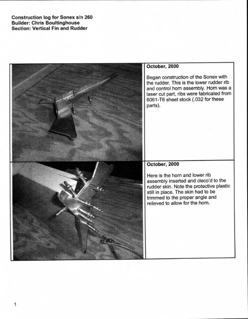
Construction log for <strong>Sonex</strong> s/n 260<strong>Build</strong>er: Chris BoultinghouseSection: Vertical Fin and RudderOctober, 2000Began construction of the <strong>Sonex</strong> withthe rudder. This is the lower rudder riband control horn assembly. Horn was alaser cut part, ribs were fabricated from6061-T6 sheet stock (.032 for theseparts).October, 2000Here is the horn and lower ribassembly inserted and cleco'd to therudder skin. Note the protective plasticstill in place. The skin had to betrimmed to the proper angle andrelieved to allow for the horn.1
Construction log for <strong>Sonex</strong> s/n 260<strong>Build</strong>er: Chris BoultinghouseSection: Vertical Fin and RudderOctober, 2000Remainder of rudder ribs cleco'd inplace.November, 2000Protective plastic removed from skin.Holes de-burred and parts ready forfinal assembly.2
Construction log for <strong>Sonex</strong> s/n 260<strong>Build</strong>er: Chris BoultinghouseSection: Vertical Fin and RudderNovember, 2000Ribs riveted in place on one side of theskin; hinge visible in front of rudder.November-December, 2000Hinge cleco'd in place. Note thecreative and colorful weights used tokeep the rudder flat during riveting. Aswas discovered later, the rudder wasn'tquite flat. In an effort to straighten it,the rivets on the hinge-line were drilledout, and the rudder slightlyrepositioned. Now it is almost straight,but the holes in the skin behind thehinge are elongated. A replacementskin has been ordered from <strong>Sonex</strong>, Ltdand a new rudder will be fabricated ata later date.3
Construction log for <strong>Sonex</strong> s/n 260<strong>Build</strong>er: Chris BoultinghouseSection: Vertical Fin and RudderJanuary, 2001This is a nose rib blank and form block.Form blocks are not provided with the<strong>Sonex</strong> kit, but the plans show thedimensions.January, 2001Rib blank and blocks in the vice, readyfor bending. The "flutes" in the aboutto-be-bentflange were made using apair of home-made fluting pliers.4
Construction log for <strong>Sonex</strong> s/n 260<strong>Build</strong>er: Chris BoultinghouseSection: Vertical Fin and RudderJanuary, 2001Flange bent. Here you can see that theform block is cut beyond 90 degrees toallow for the "spring back" that occurswhen you bend the T-6 temperedaluminum. As you can see, the flangeends up almost perfectly bent, right outof the block.January, 2001Cutting channel stock to length forvertical fin ribs and spars.5
Construction log for <strong>Sonex</strong> s/n 260<strong>Build</strong>er: Chris BoultinghouseSection: Vertical Fin and RudderJanuary, 2001Bending the attach flange on the frontof a fin rib.January, 2001All vertical fin components completeand ready for assembly. The "H"-shaped piece and the triangular piecewith the forked top are laser cut, as isthe piece with the large hole. All othercomponents are made from sheet,channel or extruded stock.6
Construction log for <strong>Sonex</strong> s/n 260<strong>Build</strong>er: Chris BoultinghouseSection: Vertical Fin and RudderJanuary, 2001Bending the vertical fin attach plate tothe required angle. What isn't visiblehere is the 27oz deadblow hammerthat was used to beat the heck out ofthe part to bend it. Yes, I'm sure therewas an easier way, but I couldn't figureit out. 0January, 2001The method may have been crude, butthe results are what matter. The angleis dead-nuts on. Note the nicelyburnished edges. These wereaccomplished with a 3M product thatcombines sandpaper and Scotch-Britein a flapper wheel that you chuck intothe drill press. Neat!7
Construction log for <strong>Sonex</strong> s/n 260<strong>Build</strong>er: Chris BoultinghouseSection: Vertical Fin and RudderJanuary, 2001And here's the piece cleco'd to thevertical fin front spar assembly. That'sthe rear spar beside it, minus a fewpieces.January, 2001This is the rear spar assemblyundergoing a trial-fit during the drillingprocess. Having the laser-cut partswith pilot holes really eases the mindwhen wondering if you have the holesin the right place!8
Construction log for <strong>Sonex</strong> s/n 260<strong>Build</strong>er: Chris BoultinghouseSection: Vertical Fin and RudderJanuary, 2001Front and rear spars riveted.January, 2001For some reason, I have no pictures ofthe vertical fin skeleton duringassembly. I guess I was too busybuilding it to take pictures! This shotshows the skin cleco'd to the left sideof the skeleton, ready to rivet. In fact,there are rivets in the non-cleco'dholes, ready to be pulled.9
Construction log for <strong>Sonex</strong> s/n 260<strong>Build</strong>er: Chris BoultinghouseSection: Vertical Fin and RudderJanuary, 2001Here's a shot of the skeleton, afterriveting the left side of the skin. Nowit's time to force the skin around, clampit, and drill the holes in the skeleton.Again, it's nice to have those pilotholes already in the skin. And theyeven lined up correctly on the skeleton!Imagine. 0January, 2001Here's the other side cleco'd. Theboard in the foreground was used(along with a helper) to press theleading edge of the skin down while itwas clamped at the trailing edge.10
Construction log for <strong>Sonex</strong> s/n 260<strong>Build</strong>er: Chris BoultinghouseSection: Vertical Fin and RudderJanuary, 2001Both sides riveted, and the "closeout"rib for the fiberglass tip is already fitted.January, 2001Speaking of that closeout rib, here it isin the brake being formed. The tip hasalready been trimmed and fitted to thefin.11
Construction log for <strong>Sonex</strong> s/n 260<strong>Build</strong>er: Chris BoultinghouseSection: Horizontal Stabilizer and ElevatorsFebruary, 2001These are the nose and tip ribs for thehorizontal stabilizer. They were madeusing the same method as shownpreviously for the vertical fin nose rib.Pre-formed channel stock has beenrough-cut to length for the stabilizerribs and spars, seen stacked on thecorner of the bench.February, 2001The stabilizer spar joiners are mostlyflat, except for the attach bracket,which sticks up like an "L". They aremade from 90 degree extrusion,however, so you end up cutting offmost of one "leg". A rough-cut wasmade with the bandsaw, duct tape wasapplied to protect it, then the remainingmaterial was removed with a routerusing an edge trimming bit. What aloud and messy job!! Not to mention abit frightening.1
Construction log for <strong>Sonex</strong> s/n 260<strong>Build</strong>er: Chris BoultinghouseSection: Horizontal Stabilizer and ElevatorsFebruary, 2001And here I am making hot aluminumchips. Note that I'm wearing hearingprotectors as well as safety glasses.I'm telling you, it's loud!February, 2001The spar joiner, after a lot of work. Andthat's just the rear. Now it's time tomake the front spar joiner!2
Construction log for <strong>Sonex</strong> s/n 260<strong>Build</strong>er: Chris BoultinghouseSection: Horizontal Stabilizer and ElevatorsFebruary, 2001Here's the starting point for the frontspar joiner; a chunk of 3/16" thick, 2"wide 6061-T6 aluminum extrusion.February, 2001This shows the "legs" rough-cut withthe bandsaw, and duct tape in place toprotect the aluminum from the bearingon the edge-trimming router bit.3
Construction log for <strong>Sonex</strong> s/n 260<strong>Build</strong>er: Chris BoultinghouseSection: Horizontal Stabilizer and ElevatorsFebruary, 2001Another view. The paint stir stick isthere to keep the part from scooting onthe bench. It's clamped at the otherend.February, 2001And here's the noisy little aluminumbeaver at work. (Okay, it's a posedshot; the bit isn't in the right place toactually be cutting.) I had it set up sothe router rested on the edge of thebench, keeping everything nice andsquare during cutting.4
Construction log for <strong>Sonex</strong> s/n 260<strong>Build</strong>er: Chris BoultinghouseSection: Horizontal Stabilizer and ElevatorsFebruary, 2001Ugh! Hot aluminum chips everywhere.It's very messy, but it makes quickwork of a job I was dreading.February, 2001The shaped front spar. Next it getsclamped to the radiused workbench leg(like the fin spar attach) and bent to thecorrect angle.5
Construction log for <strong>Sonex</strong> s/n 260<strong>Build</strong>er: Chris BoultinghouseSection: Horizontal Stabilizer and ElevatorsFebruary, 2001I drilled all the pilot holes (using thedrill press) before I bent it. This shotshows both spar joiners, a piece of rawmaterial, and the two Vixen files usedto trim the remaining material after therouter was employed.February, 2001Here are all of the stabilizer parts (lessskins) ready for assembly.6
Construction log for <strong>Sonex</strong> s/n 260<strong>Build</strong>er: Chris BoultinghouseSection: Horizontal Stabilizer and ElevatorsFebruary, 2001Now the spar joiners are assembled totheir respective outer spars (preformedchannel stock) using theobligatory clecos and rivets.iMarch, 2001This is the final assembly of the rearspar, after priming with NAPA selfetchingprimer. (Yes, after building thefin I decided to at least use somecorrosion-proofing methods, despitethe fact that <strong>Sonex</strong>, LTD deems itunnecessary.)7
Construction log for <strong>Sonex</strong> s/n 260<strong>Build</strong>er: Chris BoultinghouseSection: Horizontal Stabilizer and ElevatorsMarch, 2001Rivets going into the horizontalstabilizer rear spar.March, 2001Completed rear spar assembly.8
Construction log for <strong>Sonex</strong> s/n 260<strong>Build</strong>er: Chris BoultinghouseSection: Horizontal Stabilizer and ElevatorsMarch, 2001And now the process is repeated withthe front spar assembly.March, 2001More front spar assembly. One cannever have too many clamps, orenough different styles.9
Construction log for <strong>Sonex</strong> s/n 260<strong>Build</strong>er: Chris BoultinghouseSection: Horizontal Stabilizer and Elevators10
Construction log for <strong>Sonex</strong> s/n 260<strong>Build</strong>er: Chris BoultinghouseSection: Horizontal Stabilizer and ElevatorsMarch, 2001Now the stabilizer framework isassembled. Essentially, it is just likebuilding two vertical fin assemblies thatare inter-connected. ©March, 2001More ribs going in.11
Construction log for <strong>Sonex</strong> s/n 260<strong>Build</strong>er: Chris BoultinghouseSection: Horizontal Stabilizer and ElevatorsJune, 2001Notice the date? Yes, there was a biggap in building. Springtime bringsmany chores, like landscaping,mowing, and other "honey-do's". Oh,and notice the new workbench? I alsobought shelving and made an attemptto organize the workshop just a bit.But, progress continues at a blindingsnail's pace.June, 2001Oh yes, I forgot to mention that I alsopurchased an air compressor, andsome air tools to go along with it. Seenhere is the rivet puller (saves armcramps!) and in the previous picturethe air drill is visible.12
Construction log for <strong>Sonex</strong> s/n 260<strong>Build</strong>er: Chris BoultinghouseSection: Horizontal Stabilizer and ElevatorsJune, 2001Last of the rivets going into thestabilizer skeleton.June, 2001Skin clamped in place, checking to seeif the holes fall anywhere near thecenterline of the ribs...13
Construction log for <strong>Sonex</strong> s/n 260<strong>Build</strong>er: Chris BoultinghouseSection: Horizontal Stabilizer and ElevatorsJune, 2001Yep, the holes do line up. Time to drilland cleco!June, 2001More pictures to prove I really amworking on this project. ©14
Construction log for <strong>Sonex</strong> s/n 260<strong>Build</strong>er: Chris BoultinghouseSection: Horizontal Stabilizer and ElevatorsJune, 2001Skin cleco'd in place. It was at thispoint that I remembered a trick I'd seenon another builder's web site; usestrapping tape to keep the frame fromflexing while fitting the skins. So, theframe was taped up.June, 2001Here's the other side skin being fitted.Due to the shape of the skin, I eitherhad to hang one end off the bench, ordo one skin at a time. I opted for thelatter, till it came time to rivet them on.15
Construction log for <strong>Sonex</strong> s/n 260<strong>Build</strong>er: Chris BoultinghouseSection: Horizontal Stabilizer and ElevatorsJune, 2001At this point, I realized I needed theelevators completed in order to fit themto the stabilizer during assembly. (As Idiscovered later, this isn't really true,but it gave me a chance to work onsomething different for a while.) Here Iam using a Dremel with an angleattachmentto drill the ribs that connectto the welded steel joiner assembly.June, 2001I decided to try Alodine on the smallerinternal parts. Here's the materials andgear.16
Construction log for <strong>Sonex</strong> s/n 260<strong>Build</strong>er: Chris BoultinghouseSection: Horizontal Stabilizer and ElevatorsJune, 2001Ribs foaming away in the Alumiprep(acid) solution. This preps the metal forthe Alodine. It also handily removesSharpie marks, so be sure you can tellwhat parts go where without them!June, 2001Clean parts ready for Alodine. Don'ttouch them with your fingers, or theAlodine won't stick!17
Construction log for <strong>Sonex</strong> s/n 260<strong>Build</strong>er: Chris BoultinghouseSection: Horizontal Stabilizer and ElevatorsJune, 2001I brushed the Alodine on these parts.Since then, I've procured anotherplastic tub and I just dunk 'em. It's a loteasier, and gives more uniform color.June, 2001All done!18
Construction log for <strong>Sonex</strong> s/n 260<strong>Build</strong>er: Chris BoultinghouseSection: Horizontal Stabilizer and ElevatorsJune, 2001Since these ribs are visible, and thejoiner is black powder-coated, Idecided to paint them gloss black. TheAlumiprep/Alodine process is allegedto function as a primer, and it suredoes! The black Krylon flowed onbeautifully.June, 2001Here's a shot of the LH side of thejoiner, showing the nutplate in place.This retains the trimtab cable.19
Construction log for <strong>Sonex</strong> s/n 260<strong>Build</strong>er: Chris BoultinghouseSection: Horizontal Stabilizer and ElevatorsJune, 2001This really bugged me! I could not getthe riveter into the corner at a 90degree angle to pull this rivet. As aresult, the head is not flush with thesteel. I felt somewhat better aftervisiting a completed (and flying) <strong>Sonex</strong>project, only to find the exact samecondition. I guess it's not just me. ©June, 2001Completed elevator joiner assembly.20
Construction log for <strong>Sonex</strong> s/n 260<strong>Build</strong>er: Chris BoultinghouseSection: Horizontal Stabilizer and ElevatorsJune, 2001One marked, and one already-trimmedelevator skin. (In fact, the skin on theright already has the ribs and hingedrilled and cleco'd.)June, 2001Here's how the joiner assembly fits.Notice the "tilt" in the assembly. Thismakes for a challenging trim job on theskin!21
Construction log for <strong>Sonex</strong> s/n 260<strong>Build</strong>er: Chris BoultinghouseSection: Horizontal Stabilizer and ElevatorsJune, 2001Fitting the hinge, using a "high-tech"hinge spacing tool. It's a paint stir-stick,with two layers of cardboard taped to it.Hey, don't laugh; it works.June, 2001Another "high-tech" device. A piece ofautomotive vacuum line slipped overthe drill bit to keep it from going too farand scarring the inside of the top skin.Sure, you can buy drill stops, but why?22
Construction log for <strong>Sonex</strong> s/n 260<strong>Build</strong>er: Chris BoultinghouseSection: Horizontal Stabilizer and ElevatorsJune, 2001Here are some of the elevator ribs,after an Alodine dunk. Notice the muchdarker color. Very nice!June, 2001Elevator, final assembly.23
Construction log for <strong>Sonex</strong> s/n 260<strong>Build</strong>er: Chris BoultinghouseSection: Horizontal Stabilizer and ElevatorsJune, 2001Elevator trim tab in place on LHelevator.June, 2001RH elevator, complete except for joinerassembly (to be done after hinging tostabilizer).24
Construction log for <strong>Sonex</strong> s/n 260<strong>Build</strong>er: Chris BoultinghouseSection: Horizontal Stabilizer and ElevatorsJune, 2001Both elevators, with joiner in theforeground. The odd-looking spot onthe elevator to the right is a testpolishedsection. More pics of thatlater.July, 2001Riveting the stabilizer skin.25
Construction log for <strong>Sonex</strong> s/n 260<strong>Build</strong>er: Chris BoultinghouseSection: Horizontal Stabilizer and ElevatorsJuly, 2001Skin riveted.July, 2001Riveting the other side. Note theheadband to keep the sweat out of myeyes. Yep, summer is here!26
Construction log for <strong>Sonex</strong> s/n 260<strong>Build</strong>er: Chris BoultinghouseSection: Horizontal Stabilizer and ElevatorsJuly, 2001Upper skins (and hinges, if you lookclosely) riveted in place.July, 2001Bottom skin held in place with a boardand two stacks of ceramic floor tile.They are very heavy, and do a greatjob here.27
Construction log for <strong>Sonex</strong> s/n 260<strong>Build</strong>er: Chris BoultinghouseSection: Horizontal Stabilizer and ElevatorsJuly, 2001Here's the lower skin and skeletonafter deburring and priming. It's readyto rivet.July, 2001Here I've got some help from friends!That's Phil learning to use the clecopliers. Tommy is in the white shirt,Brian in the light blue shirt, and that'sme behind Phil.28
Construction log for <strong>Sonex</strong> s/n 260<strong>Build</strong>er: Chris BoultinghouseSection: Horizontal Stabilizer and ElevatorsJuly, 2001Lower skins cleco'd and ready forriveting.July, 2001My friend Brian is running the rivet gun.I like free help. ©29
Construction log for <strong>Sonex</strong> s/n 260<strong>Build</strong>er: Chris BoultinghouseSection: Horizontal Stabilizer and ElevatorsJuly, 2001There it is! Ready to hinge theelevators to it, drill the joiner assemblythen fit the fiberglass tips.July, 2001Elevators joiner is drilled and cleco'd.30
Construction log for <strong>Sonex</strong> s/n 260<strong>Build</strong>er: Chris BoultinghouseSection: Horizontal Stabilizer and ElevatorsJuly, 2001Elevator joiner riveted, hinges in place,pins secured with cotter keys.July, 2001Okay, I couldn't resist.31
Construction log for <strong>Sonex</strong> s/n 260<strong>Build</strong>er: Chris BoultinghouseSection: Horizontal Stabilizer and ElevatorsTips trimmed, fitted, drilled and primed.32
Construction log for <strong>Sonex</strong> s/n 260<strong>Build</strong>er: Chris BoultinghouseSection: Horizontal Stabilizer and ElevatorsJuly, 2001It's done!July, 2001Yep, it's definitely starting to look likeI'm building an airplane.33
