MAK 10 Operating Manual - CleanAir - Express Equipment Sales
MAK 10 Operating Manual - CleanAir - Express Equipment Sales
MAK 10 Operating Manual - CleanAir - Express Equipment Sales

You also want an ePaper? Increase the reach of your titles
YUMPU automatically turns print PDFs into web optimized ePapers that Google loves.
AGT Thermotechnik GmbH Page 5Electrical connection<strong>MAK</strong> sample gas conditioner must be installed as shown in the electrical circuitdiagram, illustration 5. The cross-section of access lines and the local fuse ratingmust conform to the maximum power consumption as mentioned on the rating plate.Power is supplied via cable and the mains plug. The feed length should not exceed 3m for the given fuse rating.Requirements of VDE 0<strong>10</strong>0 as well their relevant standards and guidelines must beadhered to while setting up high-voltage devices with rated voltages of up to <strong>10</strong>00 V.Caution:The mains plug must be pulled out to isolate it completely from the mains.<strong>MAK</strong> must be plugged in without voltage before switching it on so as to protectit from coming in contact with undue high voltages. This is also applicable forconnected external circuits, if any.The customer should follow the local fuse rating of devices. Technical specificationsare to be inferred from the rating plate and the technical data sheet given in thismanual. If <strong>MAK</strong> is connected to the mains voltage and switched on, either the greenlamp for operation, the yellow lamp for service or the red lamp for interruption lightsup. If the device is switched off, no lamp lights up.Please contact AGT Thermotechnik if <strong>MAK</strong> fails. When properly used, weprovide a guarantee of 1 year starting from the delivery date as per the generalsales and delivery conditions of AGT. This excludes wearing parts. Theguarantee service covers free repairs in the company or free replacement ofthe device that has been sent to the place of application free of charge. Returndeliveries must take place in suitable and sound protective packing.<strong>Operating</strong> manual - <strong>MAK</strong> sample gas conditionerSubject to technical alterations© AGT Thermotechnik GmbH <strong>10</strong>.2005
AGT Thermotechnik GmbH Page 62 Technical specificationsModel Modell <strong>MAK</strong> <strong>10</strong>-1<strong>10</strong>1 <strong>MAK</strong> <strong>10</strong>-2202 <strong>MAK</strong> <strong>10</strong>-4404 <strong>MAK</strong> <strong>10</strong>-1112 <strong>MAK</strong> <strong>10</strong>-2224Number of gas paths Anzahl der Gaswege 1 2 4 1 2Pre-separator (PS) Vorabscheider (PS) - - - 1 2Operation data BetriebsdatenGas flow per gas path Gasvolumen pro Gasweg 125 Nl/h 125 Nl/h <strong>10</strong>0 Nl/h 150 Nl/h 150 Nl/h- dew-point at inlet - Taupunkt am Eintritt 65°CGas flow per gas path Gasvolumen pro Gasweg 175 Nl/h 175 Nl/h 140 Nl/h 200 Nl/h 200 Nl/h- dew-point at inlet - Taupunkt am Eintritt 55°CGas temperature at inlet Gastemperatur am Eintritt 140°C- maximum - maximal 140°CAmbient temperature Umgebungstemperatur 5 - 45°C<strong>Operating</strong> pressure (abs.) Betriebsdruck (abs.)0.5 – 2.2 barGas dew-point at outlet Gastaupunkt am Austritt 3°C +/- 0.3Press. drop per gas path Druckverlust pro Gasweg 5 mbar (V = 125 Nl/h)Dead space per gas path Totvolumen pro Gasweg26 mlReady for start-up Betriebsbereitschaft < 5 min. < <strong>10</strong> min. < 15 min. < 5 min. < <strong>10</strong> min.Cool. capacity ta = 45°C Kühlleistung tu = 45°C 220 W 300 W 220 WMaterial of gas paths Material der GaswegeCooling transfer tube Kälteübertragungsrohr AluminiumCooling surface Kühlfläche PTFE -Coating / -BeschichtungHousing / Sealings Gehäuse / Dichtungen PVDF / VitonDesign dataKonstruktionsdatenWidth Breite 3<strong>10</strong> mm 449 mm 3<strong>10</strong> mm 449 mmHeight Höhe 266 mm 266 mm 266 mm 266 mmDepth Tiefe 271 mm 271 mm 271 mm 271 mmWeight Gewicht 16 Kg 17 Kg 20 Kg 17 kg 20 KgHousing Gehäuse Wall-mount / WandmontageHousing 19" 19" Gehäuse OptionColour Farbe RAL 7032Gas connection Gasanschluss PVDF DN 4/6Condensate connection Kondensatanschluss PVDF DN 4/6Electrical dataElektrische DatenMains connection Netzanschluss Plug / NetzsteckerAlarm: cable open-end Alarm: Anschlusskabel 250 V, 2 A, 50 VAAlarm set points Alarmgrenzwerte < + 2°C / > + <strong>10</strong>°CHousing protection class Gehäuseschutzart IP 20 EN 60529 / EN 6<strong>10</strong><strong>10</strong>Power supply Stromversorgung 230 V, 50 Hz; -15% / +15%Power consumption max. Leistungsaufnahme max. 152 W 214 W 152 WPower supply Stromversorgung 230 V, 60 Hz; -<strong>10</strong>% / + <strong>10</strong>%Power consumption Leistungsaufnahme 182 W 256 W 182 WPower supply Stromversorgung 115 V, 50/60 Hz; -<strong>10</strong>% / + <strong>10</strong>%Power consumption Leistungsaufnahme 190 W 265 W 190 W<strong>Operating</strong> manual - <strong>MAK</strong> sample gas conditionerSubject to technical alterations© AGT Thermotechnik GmbH <strong>10</strong>.2005
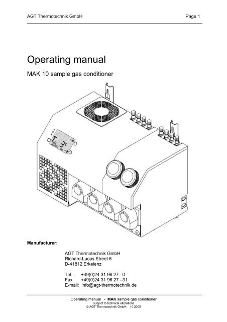
AGT Thermotechnik GmbH Page 73 Description3.1 View of <strong>MAK</strong>Illustration 1: View of <strong>MAK</strong>1 Housing for <strong>MAK</strong><strong>10</strong>-1<strong>10</strong>1; <strong>MAK</strong><strong>10</strong>-1112 and <strong>MAK</strong><strong>10</strong>-22022 Housing attachment for <strong>MAK</strong><strong>10</strong>-2224; <strong>MAK</strong><strong>10</strong>-3303 and <strong>MAK</strong><strong>10</strong>-44043 Gas inlets and outlets as well as the number of gas inlets and outlets dependon the device type4 Condensate pumps and the number of condensate pumps depend on thedevice type5 Cooling air inlet6 Cooling air outlet7 Control keypad with status displays8 Current and flow signal cable output9 Attachment rails of <strong>MAK</strong><strong>10</strong> Teflon depth filter (TF) (optional)11 Moisture guard (MS) not shown (optional)<strong>Operating</strong> manual - <strong>MAK</strong> sample gas conditionerSubject to technical alterations© AGT Thermotechnik GmbH <strong>10</strong>.2005
AGT Thermotechnik GmbH Page 114 Intended application and tasks of <strong>MAK</strong><strong>MAK</strong> is used in the sequence of sample gas conditioning, wherein cross-sensitivitymay not be observed in case of infrared analysers due to low and constant dewpoints. At no subsequent point does the dew point decrease. The analyser isprotected from the moist sample gas.Tasks of the basic version of <strong>MAK</strong> are⇒ Cooling the sample gas⇒ Separating the condensate and⇒ Discharging the condensate<strong>MAK</strong> can, if required, optionally execute other tasks for sample gas conditioning⇒ Pre-cooling the sample gas with condensate pre-separation and condensatedrain⇒ Gas cleaning⇒ Moisture guard<strong>Operating</strong> manual - <strong>MAK</strong> sample gas conditionerSubject to technical alterations© AGT Thermotechnik GmbH <strong>10</strong>.2005
AGT Thermotechnik GmbH Page 124.1 Cooling the sample gasPrinciple:<strong>MAK</strong> has 1.....4 heat exchangers I-IV, wherein the sample gas is cooled toapproximately 3C°.Refrigerant circuit:Depending on the operating conditions, the refrigerant compressor 1 compresses thevapourous refrigerant from the inlet pressure of approximately 2<strong>10</strong> kPa (= 2.1 bar) tothe condensation pressure of 800-1700 kPa (= 8-17 bar).The vapourous refrigerant is liquefied by cooling in the subsequent air-cooledrefrigerant condenser 2. The fluid refrigerant is passed through the refrigerant drier 3to the capillary tube 4.The fluid refrigerant is expanded in capillary tube 4 from the condensation pressure800-1700 kPa (= 8-17 bar) to the evaporation pressure 2<strong>10</strong> kPa (= 2.1 bar) and thenfed to evaporator 6 of heat exchanger 5.Energy is extracted from the sample gas in heat exchanger 5; the sample gas iscooled and the energy is supplied to evaporator 6. This vaporises the fluid refrigerantat an evaporation pressure of 2<strong>10</strong> kPa (= 2.1 bar, approximately +3°C). Thevapourous refrigerant is again sucked by refrigerant condenser 1 via steam dome <strong>10</strong>.Superheated steam bypass valve 9 controls the volumetric flow of refrigerant ofevaporator 6 depending on the capacity requirement so that the outlet temperature ofthe sample gas (dew point) is maintained constant. The evaporation is maintainedconstant due to the bypass. Since temperature and pressure of the refrigerant aredirectly correlated, bypass controller 9 ensures a constant dew point temperature ofthe sample gas in the entire performance range.<strong>Operating</strong> manual - <strong>MAK</strong> sample gas conditionerSubject to technical alterations© AGT Thermotechnik GmbH <strong>10</strong>.2005
AGT Thermotechnik GmbH Page 13Illustration 4: <strong>MAK</strong> flow chart1 Refrigerant compressor2 Refrigerant condenser3 Refrigerant drier4 Capillary tube5 Heat exchanger unit6 Evaporator7 Condensate separator8 Condensate pump9 Superheated steambypass valve<strong>10</strong> Steam dome11 Teflon – depth filter12 Moisture guardTLO dew point temperatureTA cooling air temperatureI – IV cooler gas path 1 – 4V – VI pre cooler,pre-separator<strong>Operating</strong> manual - <strong>MAK</strong> sample gas conditionerSubject to technical alterations© AGT Thermotechnik GmbH <strong>10</strong>.2005
AGT Thermotechnik GmbH Page 187.1 Supply connectionsAs a standard, medium connections of <strong>MAK</strong> have been designed for a 6/4 hose!The following feed lines must be connected (illustration 4):⇒ Sample gas pipeline(s) to the gas inlet connections “Gas inlets I - VI”⇒ Analyser(s) to the gas outlet connections “Gas outlets I - VI”⇒ Condensate drain to the condensate pump connections8 DecommissioningThe following steps must be executed before decommissioning <strong>MAK</strong>:⇒ Switch the device off using the electronic switch 1.⇒ Disconnect the device from the mains.⇒ Remove the feed lines; “Caution! Corrosive condensate may leak from thecondensate pump connections”. Please follow the simple guidelinesmentioned while handling the condensate.⇒ If the device has come in contact with toxic gases, the correspondingguidelines must be followed.⇒ Sample gas conditioning must be disposed off in a specialised manner.Please contact your manufacturer or an adequately qualified person for thedisposal of <strong>MAK</strong>.<strong>Operating</strong> manual - <strong>MAK</strong> sample gas conditionerSubject to technical alterations© AGT Thermotechnik GmbH <strong>10</strong>.2005
AGT Thermotechnik GmbH Page 22Dimension sheet for <strong>MAK</strong> <strong>10</strong>-3; <strong>10</strong>-4 sample gas conditioner<strong>Operating</strong> manual - <strong>MAK</strong> sample gas conditionerSubject to technical alterations© AGT Thermotechnik GmbH <strong>10</strong>.2005
AGT Thermotechnik GmbH Page 24Subject to errors and changes.AGT Thermotechnik GmbHRichard-Lucas Street 6 D-41812 ErkelenzTelephone: +49 (0)2431 9627-0 Fax: +49 (0)2431 9627-31E-mail: info@agt-thermotechnik.de Website: www.agt-thermotechnik.de<strong>Operating</strong> manual - <strong>MAK</strong> sample gas conditionerSubject to technical alterations© AGT Thermotechnik GmbH <strong>10</strong>.2005