Download - BMW side
Download - BMW side
Download - BMW side

You also want an ePaper? Increase the reach of your titles
YUMPU automatically turns print PDFs into web optimized ePapers that Google loves.
PC Diagnose V_2.08GB.fm Page 5 Friday, December 8, 2006 9:46 AMGeneral information/installationDiagnostic-capable units1.3. Diagnostic-capable unitsHeater selection for USB interfaceHeater selection for COM interfaceNOTEIf the device is not listed in Select device, the heater must be a modelwith W-Bus. W-Bus-capable heaters are grouped under the heading ofW-Bus. In this case use the W-Bus selection. The W-Bus selection containsa list of various heaters that use the same diagnostic port (see alsochapter 1.4., "OE-applications with W-Bus", page 6).Diagnosis of the following units is only possible via serial port, the USBinterface cannot be used with these units:BBW 46S; DBW 46S.5
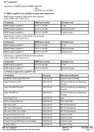
PC Diagnose V_2.08GB.fm Page 10 Friday, December 8, 2006 9:46 AMOE-applications with K-LineGeneral information/installation1.5. OE-applications with K-LineVehicle specific, K-Line capable heaters have been sumarized here.At device selection, please select the device specified in the column “deviceselection” of the table below.NOTEAvoid switching on the heater via K-Line in additional heating mode, becauseat applications without circulation pump control it can lead to overheating.NOTEFor PC-Diagnosis, a wire harness Diagnosis OEM is required.See Fig. 14.NOTEAt many OEM applications, the error memory can only be deleted via theOEM tester.Brand Model Heater Device selection Diagnose via…Alfa Romeo 166, 936 TT-Z TT-Z Fiat Vehicle diagnosis plug (adapter required),or directly at PIN 2 of the control unit.<strong>BMW</strong> X5, E53 TT-C TT-Z/C <strong>BMW</strong> PIN 2 of the control unit.<strong>BMW</strong> X5, E53 TT-Z TT-Z <strong>BMW</strong> PIN 2 of the control unit.Chrysler Voyager, RG Minivan TT-Z TT-Z PIN 2 of the control unit.Citroen Berlingo, M59 TT-Z TT-Z PSA Vehicle diagnosis plug or directly at PIN 2 of the control unit.Citroen C5, X4 TT-Z TT-Z PSA Vehicle diagnosis plug or directly at PIN 2 of the control unit.Citroen C8, V TT-Z TT-Z PSA Vehicle diagnosis plug or directly at PIN 2 of the control unit.Citroen Xsara Picasso , N68 TT-Z TT-Z PSA Vehicle diagnosis plug or directly at PIN 2 of the control unit.Fiat Ducato, 244 TT-C TT-Z/C Fiat Vehicle diagnosis plug or directly at PIN 2 of the control unit.Fiat Ducato, 244 TT-Z TT-Z Fiat Vehicle diagnosis plug or directly at PIN 2 of the control unit.Fiat Multipla, 186 TT-C TT-Z/C Fiat Vehicle diagnosis plug or directly at PIN 2 of the control unit.Fiat Stilo, 192 TT-C TT-Z/C Fiat Vehicle diagnosis plug or directly at PIN 2 of the control unit.Fiat Ulysse, V TT-Z TT-Z PSA Vehicle diagnosis plug or directly at PIN 2 of the control unit.10
PC Diagnose V_2.08GB.fm Page 11 Friday, December 8, 2006 9:46 AMGeneral information/installationOE-applications with K-LineBrand Model Heater Device selection Diagnosis via…Hyundai Trajet, F0 TT-Z TT-Z PSA Vehicle diagnosis plug (below steering column) or directly at PIN 2of the control unit.Kia Sorento, BL TT-Z TT-Z PSA Vehicle diagnosis plug (front fuse box) or directly at PIN 2 of thecontrol unit.Lancia Thesis, 841 TT-C TT-Z/C Fiat Vehicle diagnosis plug or directly at PIN 2 of the control unit.Landrover Discovery, L25 TT-Z TT-Z <strong>BMW</strong> PIN 2 of the control unit.Landrover Range Rover, L30 TT-C TT-Z/C <strong>BMW</strong> PIN 2 of the control unit.Landrover Range Rover, L30 TT-Z TT-Z <strong>BMW</strong> PIN 2 of the control unit.MG Rover 75, R40 TT-C TT-Z/C <strong>BMW</strong> PIN 2 of the control unit.MG Rover 75, R40 TT-Z TT-Z <strong>BMW</strong> PIN 2 of the control unit.Peugeot 807, V TT-Z TT-Z PSA Vehicle diagnosis plug or directly at PIN 2 of the control unit.Peugeot Jumper, U64 TT-Z TT-Z PSA Vehicle diagnosis plug or directly at PIN 2 of the control unit.Peugeot Partner, M49 TT-Z TT-Z PSA Vehicle diagnosis plug or directly at PIN 2 of the control unit.11
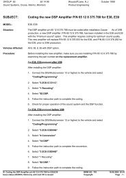
PC Diagnose V_2.08GB.fm Page 12 Friday, December 8, 2006 9:46 AMInstallation on the hard diskGeneral information/installation1.6. Installation on the hard diskNOTEWebasto does not accept liability for any data loss on your computer.Therefore, we recommend you back up your hard disk.If you already have older versions of the software installed on your computer,they must be uninstalled before the new installation.1.6.1. Installation using the installation CDTo install the Webasto PC heater diagnostic software proceed as follows.Webasto recommends using the automatic installation program:1. Close all Windows programs.2. Deactivate the virus scanner.3. Insert the installation CD in the appropriate drive.4. The installation will start automatically.If the program does not autorun, select Start > Run. Click Browseand then select “Setup.exe” on the installation CD and click OK.Alternatively select the CD drive containing the installation CD usingExplorer. In the main directory click “Setup.exe”.1.6.1.1. Webasto Thermo Test 2002 software installationNOTEIn this example, installation under Windows 2000 has been selected.The installation under other Microsoft operating systems such as Windows98 or XP is identical.Please noteIf you are working in a network and require administrator rights for theinstallation then please log on using the corresponding user name andpassword.1. Perform the steps listed in chapter 1.6.1., "Installation using the installationCD", page 12.Windows responds:Der Windows Setup-Manager führt Sie dann weiter.12
PC Diagnose V_2.08GB.fm Page 13 Friday, December 8, 2006 9:46 AMGeneral information/installationInstallation on the hard disk2. Select the required language and confirm your selection with “OK”.NOTEThe Russian version just runs under WIN 2000 and WIN XP.3. Wait for the installation preparation to finish.The Setup program responds:4. This is information about the copyright and industrial rights of thissoftware. If you agree with these clauses, click “Next” to continue.5. At this point, you are asked in which folder you want to install theWebasto Thermo Test software. If you wish to change the specifiedpath (C:\Program Files\WebastoThermoTest\), click “Browse” andselect a different folder.You are then asked whether the program should be installed for allusers of this computer or only for the current user.Please notePlease note that if you select your own path, any folders with the samename on the hard disk will be overwritten.If you select the “Current User” option, the program is only installed forthe current user.6. Confirm the settings with “Next”.13
PC Diagnose V_2.08GB.fm Page 14 Friday, December 8, 2006 9:46 AMInstallation on the hard diskGeneral information/installationConnect the USB adapter to a vacant USB connection on yourcomputer.The process runs automatically after you plug in the USB adapter.9. Windows responds:Wait until the matching drivers have been found.7. Click “Next” to start the installation.10. Click “Next” to continue the installation of the USB drivers.8. Please wait, the installation is not yet finished.14
PC Diagnose V_2.08GB.fm Page 15 Friday, December 8, 2006 9:46 AMGeneral information/installationInstallation on the hard diskWait until the matching drivers have been found11. Select “Search for a suitable driver for the device” and confirm yourselection with “Next”.13. Windows has found the suitable drivers.Click “Next” to install the driver.12. Select “CD-ROM drives” from the other sources and click “Next” toconfirm.15
PC Diagnose V_2.08GB.fm Page 16 Friday, December 8, 2006 9:46 AMInstallation on the hard diskGeneral information/installation1.6.2. <strong>Download</strong> from the Internet and installationThe latest version of the program is available from our dealer area underhttp://dealers.webasto.com.If you do not have access, please contact the regional manager responsiblefor your area or your Webasto dealer.<strong>Download</strong>:• Click the download link on the Internet.• Select save file and save the file in a suitable folder on your harddrive.14. Click “Finish” to complete installation of the USB driverssuccessfully.15. Restart the computer to complete the installation.Installation (new installation or update):• Close all Windows programs.• Open Explorer and go to the folder in which you saved the file fromthe Internet.• Double click this file.• The Windows Setup Manager will then guide you through the installation.(See chapter 1.6.1.1., "Webasto Thermo Test 2002 software installation",page 12)16
PC Diagnose V_2.08GB.fm Page 17 Friday, December 8, 2006 9:46 AMGeneral information/installationConnections1.7. ConnectionsCAUTIONThe work MUST be completed in the following sequence!– Connect the 9-pin plug or the USB plug (both cables are supplied) toa vacant serial port (COM1 or COM2) or a vacant USB port on thePC (the plug can remain connected if necessary).– Connect the 9-pin plug or USB plug to the diagnostic adapter.NOTEThe system must be switched manually between COM1 and COM2(if the PC has more than one serial port). There is no need to switch betweenthe COM and USB ports manually. The USB port to which thehardware is connected will be recognised automatically. This applieseven if there is more than one USB port.Both COM and USB connections are not allowed to be used at the sametime.CAUTIONTo avoid potential differences the vehicle must not be connected to acharger during the diagnostic procedure.CAUTIONBefore connecting to the heater ensure that there is no voltage betweenthe earths of the PC and the vehicle. Voltages in excess of 5 V may damageboth the diagnostic adapter and the PC.First connect the adapter to the positive pole and then to the earth to ensurethis.CAUTIONContact with moving parts of the vehicle (e.g. ventilator) can lead todamages.CAUTIONRisk of tripping over the supply line or data line of the adapter.WARNINGDon’t let the heater run without exhaustion.CAUTIONDon’t open the body of the heater because of risk of injuries and loss ofwarranty.NOTEThe connection cable to the heater is not allowed to be routed near thevehicle ignition system or activated electrical devices (e.g. electric drill).– Exit the diagnostic program before disconnecting the cables. Noparticular sequence must be observed for disconnecting the cables.– Connect the type-specific test adapter to the 4-pole connector of thediagnostic adapter and the heater. The heater may be switched on.17
PC Diagnose V_2.08GB.fm Page 18 Friday, December 8, 2006 9:46 AMTest procedureHeater-specific diagnosis2 Heater-specific diagnosis2.1. Test procedureNOTEThe heater must be connected to the vehicle’s electrical system but notnecessarily operating to execute a test function.If the adapter is not connected or connected to the wrong port or theheater is not on or not properly connected, an error message will be displayed.In this case check the above causes.The program monitors the connection to the heater and identifies disconnects.Irregular disconnects (e.g. pulling a plug during the test) willresult in the message “Timeout” being displayed in the status window.Specific notes on the various types of heaters:Thermo Top Z/C:If the diagnostic cable is connected, the heater (depending on theversion) cannot be started using the timer or the Telestart. In this casefirst disconnect the diagnostic cable, start the heater and then reconnectthe diagnostic cable.BBW46S/DBW46S:After the diagnosis has been started the heater enters a diagnosticmode with a run-down.Thermo Top P:The UP (circulating pump) button is not permanently activated during diagnosis;instead, it flashes at various frequencies depending on the operatingstatus of the circulating pump.Thermo Top 98:When using USB diagnosis adapter ID 9008487B, test adapter ID92566B is required.When using USB diagnosis adapter ID 9008487D via a RS232 (COM)port, test adapter ID 92566B is also required.When using USB Diagnoseadapter ID 9008487D via a USB port, anadditional test adapter is not required.DW 230..350/Thermo 230..350:The diagnostic port may suffer malfunctions when errors from this unitare saved. The diagnostic program detects these malfunctions and willrectify the problem by deleting the error memory (saved error data willbe lost).The pump pressure test is not possible.Thermo 50 MAN/trade:The Thermo 50 MAN/trade heater does not need to be switched on duringthe diagnosis.After a TRS condition has been triggered, the heater may only berestarted as follows:• Switch off the heater• To exit the diagnosis• Wait at least 10 s.18
PC Diagnose V_2.08GB.fm Page 19 Friday, December 8, 2006 9:46 AMHeater-specific diagnosisMenu: Diagnosis2.2. Menu: Diagnosis2.2.1. Select device (Start diagnosis)Open the dialog box to select the control unit using the menu commandDiagnosis/Select device or by clicking the button .UnitThermo Top VApplications with W-BusAll existing applicationsThermo Top C/Z DC C Class (W203 and W203Mopf after 09/04),DC E Class (W211),DC S Class (W220 and W220Mopf after 09/02),DC SL Class (R230),DC CLK Class (W209),Porsche Cayenne,AUDI A8 (D3),VW Phaeton (D1),VW T5,VW Touareg (MAC),<strong>BMW</strong> 7 Series (E65),Mazda 6,Mazda MPV (both U222)AT2000STAllNOTEIf the device is not listed in Select device, the heater must be a modelwith W-Bus. W-Bus-capable heaters are grouped under the heading ofW-Bus. In this case use the W-Bus selection. The W-Bus selection containsa list of various heaters that use the same diagnostic port(See also chapter 1.4., "OE-applications with W-Bus", page 6).2.2.1.1. To select the control unit and start the diagnosticprocess:• Click the button.The system performs an automatic search using the device identifierand then starts the diagnostic process.or• Mark the appropriate control unit by clicking it and then click the button.The diagnostic process will be started.or• Double click the relevant control unit.The diagnostic process will be started.2.2.2. To exit the diagnosisEnd the current diagnosis using the menu command Diagnosis/Enddiagnosis, function key F3 or by clicking the button .AT3500STThermo 90STGBW 300AllAllAll2.2.3. To restart the diagnosisYou can restart the diagnosis of the control unit you have specifiedearlier by selecting the menu command Diagnosis/Start diagnosis,pressing function key F2 or clicking the button .2.2.4. Component testOpen the dialog box of the same name using the menu command19
PC Diagnose V_2.08GB.fm Page 20 Friday, December 8, 2006 9:46 AMMenu: DiagnosisDiagnosis/Component test… or by clicking the button .• Mark the components that you wish to test in the options box, forexample the combustion air fan.• Click the button to start the test on the selected component.• Click the button to terminate the current test.NOTEThis function is not available for BBW 46 S/DBW 46 S.Note on Air Top 2000:Heating mode is terminated with a short slow-down time, after which thetest functions are available (diagnostic mode). The test starts after a furtheracknowledgement by pressing the Enter key or clicking the OKbutton. After the component test has been ended by clicking the Cancelbutton, the heater will resume normal control mode.Note on Thermo 50 MAN/trade:The component test is only available when the heater is OFF. The CO 2adjustment may only be carried out in combustion mode with the heaterin full power.2.2.5. Line primingOpen the dialog box of the same name using the menu commandDiagnosis/Prime line… or by clicking the button .• Enter the time for priming the line in seconds in the priming time box.The default is 30 seconds.• Click the button to start the line priming process.• Click the button to cancel your entry or to stop the linepriming prematurely.NOTEThe priming process cannot be stopped on some heaters.Heater-specific diagnosis2.2.6. Fuel pump testMeasuring the fuel discharge flow to the heaters Thermo Top Z, E, C, Ptrade with PC-Diagnosis "Webasto Thermo-Test".NOTEPerform the following steps when testing the fuel pump (measuringdischarge flow):1. Loosen the fuel line at the heater and put it into a suitable meteringbox (range 30 ml).2. Make all necessary connections for Webasto Thermo Test.3. Select heater: Thermo Top C,E trade, C/Z MB/DC.4. Open display Overview.5. Select menu Fuel pump test.6. Start measurement.7. During the filling check the fuel pump frequency (5.263 Hz)displayed in the overview.8. Wait 60 s.Analysis1. Compare the fuel quantity in the metering box with the setpointvalue of 20 ml (+/- 2 ml).2. When there are deviations from the setpoint value, disconnect thefuel pump from the vehicle’s fuel tank.CAUTIONRemove fuel tank cap, relief pressure, close fuel tank. Collect fuel that20
PC Diagnose V_2.08GB.fm Page 21 Friday, December 8, 2006 9:46 AMHeater-specific diagnosisruns out in a suitable container and respectively close fuel line with anappropriate tool. Connect the suction <strong>side</strong> to an unpressurised containerand lead the pressure <strong>side</strong> with a short line directly to the metering box.Then, repeat the measurement.3. In case of the same deviation, the fuel pump may be defect.Otherwise, search and remedy the failure at the fuel extraction (e.g.too high or too low pressure) or fuel line (e.g. kinked or blocked).CAUTIONWhen starting the fuel pump test, fuel is pumped!Con<strong>side</strong>r the relevant rules for safety and for the prevention of accidentsprescribed by the professional associations, the legislator, other generallyrecognized, safety-relevant rules and rules according to industrialmedicine, as well as the legal environmental protection amendments!Smoking and any kind of open fire is prohibited.Fuels can contain solvent-similar substances. Avoid skin and eye contacts.Wear protective gloves. Change and clean protective clothing frequently.Don’t bring fuel in contact with clothes. If case fuel comes incontact with clothes, change clothes immediately!Do not inhale fuel. Inhalation of fuel can cause physical damage.Don’t spill fuel. When spilling fuel, bind immediately with appropriatebonding agents and dispose environment-friendly. Make sure that nofuel is spilled in the soil!Menu: DiagnosisIn particular avoid fire, open light and sparks in the circumference of 20meters around the workspace.2.2.7. To save the data summarySelect menu command Diagnosis/Save summary… to open the reportfile dialog box.The summary shows operating data and control unit information.For additional information, see chapter 2.3.2., "Operating data", page 23and chapter 2.3.3., "Control unit information", page 23.• Enter as clear a file name as possible in the file name box for the newtext file, e.g. report_dated_011213.The file extension (.TXT) is added automatically or may be enteredas part of the file name, e.g. Test_011214.txt.• Click the button to save the summary of the diagnostic data.2.2.8. To open the data summaryTo open an existing summary of diagnostic data, open the report file dialogbox using menu command Diagnosis/Open summary…• Mark the file you want to review by clicking it. The name of the markedfile will be transferred into the file name box.• Click the button or double click the file name to open the textfile.• The Display summary view will be opened.• Click the button to close the view.2.2.9. Start test recordUse the Diagnosis/Start measurement recording… menu command toopen the Protocol file dialog box.• Enter as clear a name as possible into the protocol file name box forthe new text file, e.g. protocol_dated_011213.21
PC Diagnose V_2.08GB.fm Page 22 Friday, December 8, 2006 9:46 AMMenu: DiagnosisHeater-specific diagnosisThe file extension (.TXT) is added automatically or may be enteredas part of the file name, e.g. Test_011214.txt.• Enter the recording interval (the default is 10 seconds).NOTEWhen you have finished the diagnosis, end the measurement recording.2.2.10. To end measurement recording• The button starts the recording.• Use the Diagnosis/Measurement recording menu command to endmeasurement recording.22
PC Diagnose V_2.08GB.fm Page 23 Friday, December 8, 2006 9:46 AMHeater-specific diagnosisMenu: View2.3. Menu: ViewYou can select between different views in order to see different displaysand data about the heaters:2.3.1. Overview windowThis view gives you an overview on the values during the diagnosis.In addition to the operating voltage, temperature, etc. the device statusis also shown.• Use the View/Overview window… menu command or click thebutton to open the Overview window.2.3.5. Protocol displayThis protocol display view lists all the statuses of the heater during thediagnosis.• Open the last of the five views of the diagnostic results using menucommand View/Protocol display… or by clicking the button .• To close this view click the square at the far right of the window titlebar.2.3.2. Operating dataThe operating data view gives you an overview of a number of parametersin addition to the values that have been found and the units for them.• Use the View/Operating data… menu command or click thebutton to open the Operating data..2.3.3. Control unit informationThe device information view contains a list of all the information andvalues relating to the connected device.• Use the View/Control unit information… menu command or click thebutton to open the Control unit information.2.3.4. Trend graphicThe graphical trend view shows the sequence of the heater values overtime in a diagram. Right-clicking the display with the mouse displays ashortcut menu for the displayed values. You can show or hide theindividual values by clicking here. The same thing applies to the displaysin chapter 2.3.5., "Protocol display", page 23.• Use the View/Trend graphic… menu command or click the buttonto open the Trend graphic.23
PC Diagnose V_2.08GB.fm Page 24 Friday, December 8, 2006 9:46 AMMenu: Error memoryHeater-specific diagnosis2.4. Menu: Error memory2.4.1. To display the error list• Open the error display window using menu command Error memory/Display error list… or by clicking the button .• This view displays a list of all the errors saved in the control unittogether with the values that occurred during the error. Each error islisted separately to distinguish clearly between them.• If you click an error, an explanation of that error will be displayed.2.4.2. To delete the error memoryTo delete all the entries in the error memory select menu commandError memory/Delete error memory …, function key F5, or click thebutton .NOTEPlease note that after they have been deleted, the error values can nolonger be reviewed. If necessary you should print out the error valuesbefore you delete them (see chapter 2.5., "Menu: Print", page 25).24
PC Diagnose V_2.08GB.fm Page 25 Friday, December 8, 2006 9:46 AMHeater-specific diagnosisMenu: Print2.5. Menu: Print2.5.1. To print the summaryTo print a summary select menu point Print/Summary, function key F12,or click the button ,.25
PC Diagnose V_2.08GB.fm Page 26 Friday, December 8, 2006 9:46 AMMenu: Control (depending on heater version)Heater-specific diagnosis2.6. Menu: Control (depending on heater version)2.6.1. OffTo switch off the heater select menu command Control/Off, function keyF4, or click the button .2.6.2. OnTo switch on the heater select menu command Control/On, or click thebutton .2.6.3. Auxilliary heatingIf you wish to use auxiliary heating mode, select menu commandControl/Auxiliary heating, or click the button .2.6.4. Additional heatingIf you wish to use additional heating mode select menu commandControl/Additional heating, or click the button ,.2.6.5. VentilationIf you wish to use ventilation mode select menu command Control/Ventilation, or click the button .2.6.6. Boost modeIf you wish to use boost mode select menu command Control/Boostmode.2.6.7. Circulating pumpTo switch on the circulation pump select menu command Control/Circulation pump.NOTENot all of the control commands are available for all of the heaters.26
PC Diagnose V_2.08GB.fm Page 27 Friday, December 8, 2006 9:46 AMHeater-specific diagnosisMenu: Calibration2.7. Menu: Calibration2.7.1. CO 2 adjustmentTo carry out the calibration process select menu command Calibration/CO 2 adjustment or click the button .NOTEThis function is only available when the heater is in certain statuses.Please also read the corresponding chapter in the workshop manual ofthe heater in question!27
PC Diagnose V_2.08GB.fm Page 28 Friday, December 8, 2006 9:46 AMMenu: ToolsHeater-specific diagnosis2.8. Menu: ToolsNOTEIf the diagnostic adapter is connected to the USB port, it will be automaticallyrecognised by Windows. No settings are required.The Tools menu provides you with two menu commands to configureyour computer:2.8.1. COM port• Open the COM port selection dialog box using menu commandTools/COM port.• Select the COM port (COM1 or COM2) you want to use to connect tothe external device.• Click the button to confirm your selection.CAUTIONIf the COM port you wish to use is not displayed, this means that the portis being used by a different program. In this case quit all yourapplications and restart Thermo Test.2.8.2. StartupSelect menu command Tools/Startup if you wish to restart the connectionto the control unit automatically after an interrupt. This is an advantageif the operating voltage is disconnected frequently during the test.The selection will be confirmed by a tick being placed next to the Startupmenu command.If you reselect the menu command or terminate the connection, thisselection will be cancelled.28
PC Diagnose V_2.08GB.fm Page 29 Friday, December 8, 2006 9:46 AMHeater-specific diagnosisMenu: Window2.9. Menu: WindowThe Window menu enables you to influence how open dialog boxes andview windows are displayed:2.9.1. OverlappingSelect menu command Window/Overlapping if you want open windowsto be arranged overlapping each other.2.9.2. Side-by-<strong>side</strong>Select menu command Window/Side-by-<strong>side</strong> if you want open windowsto be of the same size and arranged next to each other without anyoverlap.2.9.3. Close allSelect menu command Window/Close all if you want to close all openwindows.2.9.4. To select an open windowSelect the Select an open window menu command if you want to switchbetween windows that are open at the same time.29
PC Diagnose V_2.08GB.fm Page 30 Friday, December 8, 2006 9:46 AMMenu: HelpHeater-specific diagnosis2.10. Menu: Help2.10.1. HelpThis menu displays help topics relating to this diagnostic software.• To obtain help on the program and problems, select menu commandHelp/Help or click the button . From this window you can go toinstructions that will give you a step by step guide to using WebastoThermo Test 2002 or you can view various types of referenceinformation.• As soon as you have opened the help topic you can click theContents button at any time to return to the contents window.2.10.2. Program informationThis displays the version of this diagnostic software:• Select the Help/Program information… menu command or click thebutton to obtain information on your WTT version.• Click to close the program information window.30
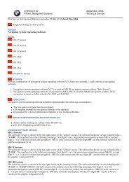
PC Diagnose V_2.08GB.fm Page 31 Friday, December 8, 2006 9:46 AMService modules for components and accessoriesIPCU intelligent PWM control unit3 Service modules for components and accessories3.1. IPCU intelligent PWM control unit3.1.1. IPCU programmingThe button “Set selected parameters” sets the predefined parameter forthe selected vehicle module under “IPCU programming”.The parameter values can also be changed individually.Programming of the selected parameters is only performed using thebutton “IPCU programming”.NOTE:When selecting user-defined parameters, make sure they are suitablefor the requirements of the fan motor. Incorrect parameters can lead toa malfunction or damage to the fan motor when the module is operating.This dialog box is used for programming an electrical system, referredto as IPCU module for short, for controlling vehicle fan motors.The current settings of the IPCU module are continuously read out anddisplayed under “Current IPCU settings”.A list of vehicle modules can be found in “Vehicle-specific parameters”.31
PC Diagnose V_2.08GB.fm Page 32 Friday, December 8, 2006 9:46 AMIPMU Intelligent PWM Master UnitService modules for components and accessories3.2. IPMU Intelligent PWM Master Unit3.2.1. Reading out vehicle specific parameters via IPMUIn case the correct vehicle specific parameters for programming theIPCU module are unknown, these can be read out via a IPMU moduleand special measuring equipment.After the IPMU module is plugged onto the USB DIAGNOSTICSadapter and connected with the vehicle via the measuring equipment,the readout can be started with this dialog box.For that purpose, click “Start measurement”.After a successful measurement the message PWM VALUES READOUT SUCCESSFULLY appears.In order to program an IPCU with these values, select the IPCU from thedevice selection list, without closing the Webasto Thermo Test 2002program. Then, the measured values will be transferred automaticallyinto the window "IPCU programming values" of the IPCU dialog box.Programming the measured values is accomplished by clicking thebutton "IPCU programming”.NOTE:The IPMU and the necessary measuring equipment can be purchasedunder order no. 9016656A.NOTE:The function "High <strong>side</strong> active" or "Low <strong>side</strong> active" cannot beestablished with the IPMU. After a successful measurement the functionis always indicated as "High <strong>side</strong> active”.If controlling of the vehicle fan motors is not possible, please change thefunction to "Low <strong>side</strong> active".32
PC Diagnose V_2.08GB.fm Page 33 Friday, December 8, 2006 9:46 AMService modules for components and accessoriesTelestart T100HTM3.3. Telestart T100HTM3.3.1. Programming the system levelHeating Time Management (HTM) in the Telestart receiver calculatesthe heating duration depending on the prevailing temperature and thecomfort level (C1 to C5) selected using the hand-held transmitter.Comfort levelWe recommend comfort level 2/3 as the basic setting. However, the usercan adapt the comfort level according to his or her individualrequirements using the HTM transmitter. The specialist workshop canselect a higher system level in advance to adapt the system inaccordance with specific requirements.System levelThe system level setting is used for the default setting depending on thecorresponding vehicle type. This setting can only be made by theWebasto specialist workshop or an installation partner using thediagnostic software.We recommend the following typical default settings for the systemlevel:S0: For small cars and saloonsS1: For off-roaders, estate cars, SUVs and in general for vehicles with aspacious interiorS2/S3 : Only in regions with very cold outdoor temperatures or if thecustomer has special requirements.Altering the system levels makes it possible to adapt the heatingduration to the given features of a particular vehicle heating system.The maximum heating duration (below -20 °C) is specified for eachsystem level in the dialog box.The minimum heating duration (above +10 °C) is always 10 minutes.The heating duration between these two temperature values varies withan approximately linear progression.33
PC Diagnose V_2.08GB.fm Page 34 Friday, December 8, 2006 9:46 AMGeneralTroubleshooting4 Troubleshooting4.1. GeneralWhen you select a test function, an error message is displayed.• Check if the diagnostic adapter is connected to the selected serialport or the USB port on the PC and that heater is properly connected.• Check whether the heater is switched on and is receiving power.• Is there an earth connection (apart from via the diagnostic cable)between the PC and the vehicle? If so immediately disconnect thediagnostic cable and disconnect the relevant connection to preventdamage to the adapter and PC.• The control unit may be defective (check with a different unit beforereplacing it).• A control unit that has no diagnostic capability may have beenselected.• An incorrect connection on the control unit has been used for thediagnostic cable.• If you are using an RS232 (COM) port:If another program (e.g. keypad or mouse) is accessing the port, thisapplication must be closed.34