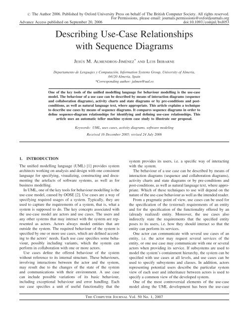
Describing Use-Case Relationships with Sequence Diagrams
Describing Use-Case Relationships with Sequence Diagrams
Describing Use-Case Relationships with Sequence Diagrams

Create successful ePaper yourself
Turn your PDF publications into a flip-book with our unique Google optimized e-Paper software.
USE-CASE RELATIONSHIPS WITH SEQUENCE DIAGRAMS 117relationships called inclusion, generalization and extension,introduced by Jacobson [3]. These relations have someunstable semantics along the UML development. They havereceived several interpretations [3–18], reflecting a greatdeal of confusion among developers.This article explains a technique to describe use cases bymeans of sequence diagrams. It compares sequence diagramsin order to define sequence-diagram relationships for identifyingand defining use-case relationships.<strong>Sequence</strong>-diagram relationships are defined according tothe most accepted semantics for use-case relationships. Infact, we believe that our proposal could be useful for abetter understanding of the cited semantics. We believe thatone of the contributions of our work is to provide a semanticsof use-case relationships by means of sequence diagrams. Sofar, most of the works concerning use cases and their relationshipshave used the UML metamodel or pseudocode todescribe the semantics. However, for practical reasons, andin order to fulfil the UML philosophy, use-case modellingshould be integrated into other UML models to support thedetection of mistakes and missing details in use cases and tofacilitate the proper formulation of their relationships. Inaddition, we also present a discussion on how the developmentprocess and, in general, the developer decisions affect bothuse-case modelling and sequence-diagram modelling, in particular,in the identification of use-case relationships.Our proposal involves that each use case is described bymeans of a sequence diagram. However, it is well knownthat use cases can be specified or refined in several ways:<strong>with</strong> some other UML models, pre–post conditions ornatural language. In addition, some use cases may not representsequences of interaction steps in the developedsystem but represent human tasks, services required to existentsoftware and so on. Therefore, our proposal could seem torequire a sort of tight coupling between use-cases modellingand sequence-diagram modelling. However, this is not ouraim, instead we describe a specific method for specifyinguse cases by means of sequence diagrams which can beadopted in some other parts of the developed system. Insummary, the developer is still free to use the use-casemodel for the other cited purposes.However, the requirement analysis technique presented inour proposal may still be used for other parts of the system.In our opinion, similar relationships could be defined forother notations such as activity diagrams and statecharts. Asfuture work, we might consider the study of such relationshipsfor other notations.This work is organized as follows. In Section 2, we presentthe most accepted semantics of use cases and their relations.Section 3 describes our technique: how to describe use casesby means of sequence diagrams and how to make the correspondencebetween the inclusion, extension and generalizationrelationships and the sequence-diagram relationships. Finally,Section 4 discusses some conclusions and future work.2. USE CASES AND USE-CASE RELATIONSHIPSIn spite of many attempts to clarify the use-case relationships,there are many objections against how the UML developmenthas defined the semantics of use cases and their relationships.Some authors [3, 13] and the UML reference manual [1]agree that a use case is a high-level description of what thesystem is supposed to do, whose aim is to capture thesystem requirements. However, use cases have to be specified,that is, many particular cases of a use case can be described. Inother words, if a use case represents a user interaction, manyvariants of this user interaction can be described.The variants of a use case can correspond to alternativecourses or fragments of behaviour [7, 8, 14] inserted in themain behaviour, describing additional behaviour for particularcases or exception handling. In this respect, there are twokinds of use cases [3, 6–10]. The first one consists of theso-called abstract use cases, which are fragments of behaviourof another use case (called base use case) and are separatelyspecified. Their aim is to factor out common flows ofuse cases [3], but they cannot be instantiated, that is, they donot completely do an operation, and they cannot be run individually[8]. It is supposed that these abstract use cases areinserted in the running of the base use case at a certainposition.In addition, some authors [3, 13] agree that an ‘include’relationship is not functional decomposition, i.e. inclusionshould not be used for decomposing the behaviour of a usecase in steps. Some other authors [3, 8, 13] claim that inclusioncorresponds to fragments of interaction steps which areinserted in the base use case. Therefore, included use casesare abstract use cases, whereas base use cases are concreteuse cases. In other words, whenever a use case includesanother use case, the included use case is inserted into themain use case description. The second kind of use cases isthe concrete use cases, which has a complete behaviour andis separately runnable.In addition, some authors [7, 8] claim that the fragment ofinteraction, represented by an included use case, should beencapsulated and that inclusion does not have interleavingsemantics. Interleaving means the access from the base usecase to the abstract use-case space (attributes, methods andso on) and/or from the abstract to the base use case.However, throughout the UML development, the generalizationrelationship has been confused <strong>with</strong> the ‘extend’relationship. However, most experts on UML [3, 5] agreethat generalization is a way of describing particular cases ofuse cases. In other words, generalization/specialization isrelated to the concept of substitution or replacement of a usecase by another <strong>with</strong> at least the same behaviour.According to this, some authors [6–8] have found out thatthe UML semantics (expressed in the UML metamodel) isconfusing regarding the ‘extend’ relationships. It is clarifiedin Metz et al. [14, 15], assuming that ‘extend’ should beTHE COMPUTER JOURNAL Vol. 50 No. 1, 2007
USE-CASE RELATIONSHIPS WITH SEQUENCE DIAGRAMS 119FIGURE 2. A sequence diagram of the Register use case.(i.e. Register use case) in the ATM and can Make Transactionsonce registered; (c) finally, the Bank, an externalsystem that interacts <strong>with</strong> the ATM in order to carry out thebank operations.Now, in our technique, each use case is described by meansof a unique sequence of behaviour in which the developers candecide whether they includes all the steps and variants. That is,pieces of behaviour could separately be described by means ofanother sequence diagram. Here, a sequence should beunderstood as a juxtaposition of steps which can be conditioned,that is, the sequence can include steps such as ‘ifsomething happens then’ or even repetition structures suchas ‘for each element do’.In UML 2.0, there exist constructors to specify these kindsof ‘programming flow structures’ such as opt and loop.Given that a use case has a unique specification, specifications(i.e. sequence diagrams) are identified <strong>with</strong> use cases. In otherwords, use cases are specified by several scenarios describedTHE COMPUTER JOURNAL Vol. 50 No. 1, 2007
120 J. M. ALMENDROS-JIMÉNEZ AND L. IRIBARNEin a single diagram. Included use cases, use-case extensionsand generalizations can thus uniformly be handled. This willbe explained later on.In Figure 2, the Register use case is specified by means ofa sequence diagram in which a successful behaviour isdescribed, that is, both the card number and the pin arevalid. It is supposed that the developer has decided toinclude both validations in order to describe the basic behaviour.However, whenever the card is not valid or the pin isincorrect, the alternative course should be separately describedfrom other use cases, in particular, they will correspond toextensions of this base use case.Alternatively, the developer could include all the alternativecourses in a unique sequence diagram handling the invalidcard and invalid pin cases inside the opt constructor. Thisdepends on the number of alternative branches and alsowhether the system designer is still in a step of development,which will be refined later.FIGURE 3. Deployment of the interactions for the Client actorinto the ATM system.3.2. Associations between use cases and actorsNow, an association between a use case and an actor meansthat an actor participates in the behaviour described by theuse case. This participation involves interaction: an observableresult by the actor. In addition, if a use case includes anotherone, the actor necessarily interacts <strong>with</strong> the included usecase. The same happens <strong>with</strong> use-case extensions anduse-case specializations.In Figure 3, the Client actor interacts <strong>with</strong> the MakeTransactions use case. As we can see, this includes twoother use cases, Withdraw Cash and Recharge Phone-Card. Although there is no association directly connectingthe actors (Client and Bank) and the included use cases,the actors can observe and therefore interact <strong>with</strong> thesystem to <strong>with</strong>draw cash or recharge a phone card.However, the Mobile actor interacts only in the RechargePhoneCard use case, given that it is directly connected tothis use case.One of the reasons why the actor interaction <strong>with</strong> the usecase is required is to prevent the inclusion from correspondingto functional decomposition referring to internal processing.The use-case model shows an external view of the system[3], and therefore, each use case should interact <strong>with</strong> theactors representing the system boundaries.3.3. Included use casesAn included use case specifies a fragment of the base use-casebehaviour. In this fragment, the actor connected to the base usecase participates. The included use case is inserted in the specificationof the base use-case behaviour. In fact, the name ofthe included use case is inserted as one of the sequence steps ofthe base.The included use case can be either mandatory or optional,occurring in sentences such as ‘if this condition occurs then,name of use case.’ or ‘for each element do ,name ofthe use case.’. The included use case is encapsulated andthere is no interleaving <strong>with</strong> the base use case.The base use case cannot access the included use case,except for the retrieval of the observable result by the actor.Therefore, included use cases are encapsulated by means of‘methods’ which can specify the data input as parametersand the data output as a return parameter. In addition, theactor connected to the base use case also interacts <strong>with</strong> theincluded use-case specification.Figure 4 shows the behaviour description of the MakeTransactions use case by means of a sequence diagram.The Withdraw Cash and Recharge PhoneCard use caseshave been introduced in the base sequence diagram (thebase use case) using the UML 2.0 notation. Both theinclusions are conditioned if in, the first case, the useroption is ‘<strong>with</strong>draw’, and in the second case, the user optionis ‘recharge’. Let us remark that included use cases can beout of ‘opt’ boxes when the running of included use cases ismandatory.Included use cases are used for the following two mainreasons.(i) The base use case is too big, and it is specified bymeans of fragments of specification, that is, the behaviouris decomposed into several steps. However, thespecification of the base use case describes how thesesteps are combined in order to obtain a uniquebehaviour.(ii) A use case was specified in a previous step of thedevelopment process and now it is reused. Thereuse of specifications is a good practice in softwareTHE COMPUTER JOURNAL Vol. 50 No. 1, 2007
USE-CASE RELATIONSHIPS WITH SEQUENCE DIAGRAMS 121FIGURE 4. <strong>Sequence</strong> diagram of Make Transactions.development. The developer can reuse the previouslyspecified processes in a new version of thesystem or a new system. In fact, the developermight work <strong>with</strong> a library of use-case specificationsfor reusing.The inclusion is not used for functional decompositionbecause of the following.(i) The actors always interact <strong>with</strong> use cases, and therefore,internal processing is removed from theuse-case diagram.(ii) The included use case is supposed to describe a fragmentof behaviour extracted from the base use case.However, an extensive extraction causes too biguse-case diagrams <strong>with</strong> many included use cases ofsmall size (i.e. use cases <strong>with</strong> few steps of execution).In addition, the use-case model is supposed to be usedin the early steps of system analysis, where littleinformation about system components is available,and therefore decomposition is useless.In summary, the use of inclusion for functional decompositionis not practical, and another kind of diagrams (in ourcase, sequence diagrams) will be used instead. Finally, giventhat the base use case depends on the included use case tobe runnable, the arrow will go from the base use case up tothe included use case.THE COMPUTER JOURNAL Vol. 50 No. 1, 2007
122 J. M. ALMENDROS-JIMÉNEZ AND L. IRIBARNEFIGURE 5. A generalized sequence diagram of the Transaction use case.3.4. GeneralizationA specialization of a use case is a use case whose sequence ofsteps have been specialized. There are two cases in ourtechnique.(i) The specialized use case replaces some steps byspecialized steps.(ii) The specialized use case introduces new steps ofexecution but <strong>with</strong>out interleaving.For instance, in Figure 3, all ATM transactions that a clientcan make have been generalized. The Transaction use caseis a general or abstract use case and each specific type of transactionis a particular case. The behaviour of the abstract usecase (Transaction) is described by means of a generalsequence diagram (Figure 5). The specialized WithdrawCash use case (Figure 6) replaces some steps of the Transactionsequence diagram and modifies the general name ofthe methods. For instance, the operation() method in theTHE COMPUTER JOURNAL Vol. 50 No. 1, 2007
USE-CASE RELATIONSHIPS WITH SEQUENCE DIAGRAMS 123FIGURE 6. A transaction specialization sequence to Withdraw Cash.abstract sequence diagram has been rewritten by the <strong>with</strong>draw()method in the specialized sequence. Methods 2, 7and 8 have also been modified to implement Withdrawingcash. Besides, method 11 has been rewritten as an optionaloperation to deliver cash when the transaction has beensuccessful.However, Figure 7 shows the specialized sequence torecharge a phone card. The specialization replaces somesteps of the generalization, and it also introduces a new andlast step of execution to send an SMS to the client’s mobilenotifying the result of the recharge transaction.The idea is that specialized use cases correspond to theconcept of inheritance of object-oriented programming. Thatis, assuming that the designers have a use case previouslyspecified, they would like to have a new and complete usecase <strong>with</strong> some slight modifications which consist of addingnew interaction steps (conditioned or not) or modifyingsome existent ones. However, interaction steps can only bemodified when they specialize the old version. In otherwords, the specialized use case adds new steps and rewritesthe existing ones.In general, methods can be replaced whenever the developerknows they represent similar operations. Boolean conditionscan also be replaced by more restrictive ones, and finally,new interactions can be introduced. However, in order toavoid interleaving semantics, the introduced interactions canTHE COMPUTER JOURNAL Vol. 50 No. 1, 2007
USE-CASE RELATIONSHIPS WITH SEQUENCE DIAGRAMS 125FIGURE 8. A more detailed use-case description of the ATM system.included use case is inserted in the specification of the base usecase, and then, we know where the included use case isinserted.However, the extension is omitted from the specification ofthe base use case, and now, an alternative course is specified atsome point of the base use case (called extension point) representingthe extension. In addition, a rejoint point is specified.The reason why the developers may use inclusions andextensions is because the sequence diagram of the base usecase is too big and they would like to specify it <strong>with</strong> severalsequence diagrams.Thus, the developer uses the inclusion to specify alternativecourses or exception handling, except when some alternativecourses require to break the main sequence and require toabuse of ‘optional’ branches in the sequence diagram. In thelatter case, the use of extensions seems to be more suitable,once the alternative courses and exception handling haveseparately been specified.In addition, following Metz et al. [14, 15], in our technique,we have considered the extension and rejoint points establishingat which point the main sequence is broken and where theextension point rejoins the main sequence. We haveTHE COMPUTER JOURNAL Vol. 50 No. 1, 2007
126 J. M. ALMENDROS-JIMÉNEZ AND L. IRIBARNEdistinguished four kinds of extensions, which will be discussedlater.According to the UML semantics and Jacobson [3], thearrow goes from the extending use case up to the base usecase, because the base use case defines a complete sequenceof behaviour, but the extension cannot be runnable <strong>with</strong>outthe base use case. Let us remark that this is the oppositecase of the inclusion in which the base use case contains inits specification the included use case and therefore is notrunnable <strong>with</strong>out the included use case.Finally, there exists an additional reason for using extensions.Let us suppose that we have a general use case inwhich we would like to use the specialization in order todefine a new use case, but the new use case should modifythe main sequence by adding new branches. We have consideredthat specialization can add new interactions but<strong>with</strong>out modifying the main sequence. However, we can usethe extension over an abstract-specialized use case in whichthe extension inserts the new interactions.Let us now pay attention to Figure 8 to illustrate the extendrelationship.Figure 8 shows a more detailed description of the use casesof the ATM system. We have used again the UML 2.0 notationto describe the ,,extend.. relationship between two usecases. An extension is complemented by a UML note. Thenote introduces a boolean condition and an extension pointwhere the fragment of behaviour extends the base use case.The extension points are defined by means of a tuple:,after, before.. For instance, a tuple ,4,9. meansthat the extension point where the extending use case isinserted in the base use case is after the method 4 andrejoins in method 9.Using tuples for extensions points, we can consider the followingfour kinds of extensions.(i) ‘Same point’. Whenever after=before, that is, theextension and rejoint points are the same. In otherwords, the extension breaks the main sequence but itreturns to the same point. It can be considered as aninvocation.(ii) ‘After that’. Whenever after,before, that is, themain sequence is broken and some interactions areremoved from the main sequence. It can be consideredas a bifurcation.(iii) ‘Before that’. Whenever after.before, that is, themain sequence is broken and the extension returns to aprevious step in the main sequence. It can be consideredas a loop.(iv) ‘No return’. Whenever before=no return, that is,the main sequence is broken, but the extension neverreturns to the main sequence. It is used for exceptionhandling.For example, the Withdraw Cash use case has an ’afterthat’ extension point when the connection <strong>with</strong> the bank isnot possible and the ATM system operates <strong>with</strong> the amountavailable in stock (Withdraw in stock).The extended behaviour is described by the Withdraw instock sequence diagram shown in Figure 9a. As we can seein the use-case model, the extended use case has an extensionpoint when the condition (status is not connected)occurs. If it happens, the behaviour sequence of the Withdrawin stock use case, shown in Figure 9a, is runbetween methods 4 and 9 in the base sequence diagram(Figure 6).Figure 9d and b shows two sequence examples of thebefore that and no return extension points, respectively.(i) In the first one, if the amount is out of the requiredlimits, then an exception, modelled by a beforethat extension point occurs. A before that extensionpoint is similar to a loop sequence.(ii) In the second one, if the card is not valid, the ATMdefinitively rejects the ATM operation and the mainsequence is broken. Thus, this is the case of a noreturn extension point.Finally, we have a case of the same point extension inFigure 9c, when the clients request their account movementsbefore the new transaction is achieved.Extensions are encapsulated, that is, the base use casecannot access the extending use case. This does not makesense given that the base use case does not include the extensionin its specification.3.6. Abstract and concrete use casesBase use cases and specializations are concrete use cases.Included use cases and extensions are abstract use cases,except when they are connected to an actor.For instance, in our running example, there is an included usecase which is connected to an actor. In Figure 8, the actorMobile is connected to the Recharge PhoneCard use case,which is included in the Make Transactions use case. Supposingthat an actor is connected to the included use case, itdefines a concrete use case instead of an abstract one.4. CONCLUSIONS AND FUTURE WORKIn this article, we have suggested a technique for describinguse cases by means of sequence diagrams, according to themost accepted semantics of use cases and use-case relationships.The use-case diagrams help the developer to identifythe requirements of the system to be developed. <strong>Sequence</strong> diagramsallow the developer to discover behavioural details ofthe system or to better describe the already existing ones.In this article, we have shown that a direct correspondencebetween the requirements identified in the use cases <strong>with</strong> UMLsequence diagrams is feasible.THE COMPUTER JOURNAL Vol. 50 No. 1, 2007
USE-CASE RELATIONSHIPS WITH SEQUENCE DIAGRAMS 127FIGURE 9. The four kinds of use-case extensions.As a future work, we would firstly like to provide a frameworkfor specifying pattern design, once generalization/specialization can be combined <strong>with</strong> inclusions and extensionsin order to define generic patterns of components,tasks and so on. Secondly, we could study the same kind ofrelationships in other notations such as activity diagramsand statecharts. Thirdly, we plan to extend our proposal todeal <strong>with</strong> automated code generation and component-baseddevelopment, by parsing and translating use cases, relationshipsand specifications into a class diagram and code.Finally, we would like to incorporate all these ideas into aCASE tool and integrate our technique into the whole developmentprocess, especially into our previous works about usecases and activity diagrams [18] and use cases and graphicaluser interfaces design [17].ACKNOWLEDGEMENTSThe authors would like to thank the anonymous referees fortheir insightful comments and suggestions, which greatlyhelped them improve the contents and readability of thearticle. This work has been partially supported by the EU(FEDER) and the Spanish MEC under grantsTIN2005-09207-C03-02 and TIN2006- 06698.REFERENCES[1] UML 2. (2005) Unified modeling language specification. ObjectManagement Group, Needham, USA.[2] Jacobson, I., Jonsson, P., Christerson, M. and Övergaard, G.(1992) Object-Oriented Software Engineering: A <strong>Use</strong> <strong>Case</strong>Driven Approach. Addison-Wesley, MA, USA.THE COMPUTER JOURNAL Vol. 50 No. 1, 2007