Kirchhoff's Laws - Mercer University Physics
Kirchhoff's Laws - Mercer University Physics
Kirchhoff's Laws - Mercer University Physics

Create successful ePaper yourself
Turn your PDF publications into a flip-book with our unique Google optimized e-Paper software.
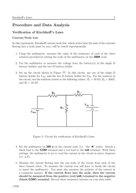
Kirchhoff’s <strong>Laws</strong> 5Procedure and Data AnalysisVerification of Kirchhoff’s <strong>Laws</strong>Current/Node LawIn this experiment, Kirchhoff current/node law, which states that the sum of the currentsflowing into a node must be zero, will be tested experimentally.1. Using the multimeter, measure the value of the resistance of each of the threeresistors provided by setting the scale of the multimeter on the 200K scale.2. Use the multimeter to measure the voltage from the battery(s) in the single Dbattery holders and the two D battery holder.3. Set up the circuit shown in Figure ??. In this circuit, use one of the single Dbattery holder for V B1a and the two D battery holder for V B2 . For the resistors inthe circuit, use the resistors closest to the following values: R 1 = 50 kΩ, R 2 = 20kΩ,and R 3 = 10 kΩ.Figure 5: Circuit for verification of Kirchhoff’s <strong>Laws</strong>4. Set the multimeter on 200 u on the current scale (i.e. ‘the ‘A” scale). Attach ablack lead to the COM terminal and a red lead to the mA terminal. With thesesettings, the multimeter is set to read the current in the circuit in micro Amperes(i.e. µA).5. Measure the current flowing into the top node of the circuit from each of thethree branch wires. To measure the current you will have to break the circuitto insert the multimeter. You must also measure the polarity of the current ina consistent manner. If the current flows into the node, then the currentshould be measured from the positive (red/mA) terminal to the negative(black/COM) terminal. Record these measured currents on your data table.v:F06