Kirchhoff's Laws - Mercer University Physics
Kirchhoff's Laws - Mercer University Physics
Kirchhoff's Laws - Mercer University Physics

Create successful ePaper yourself
Turn your PDF publications into a flip-book with our unique Google optimized e-Paper software.
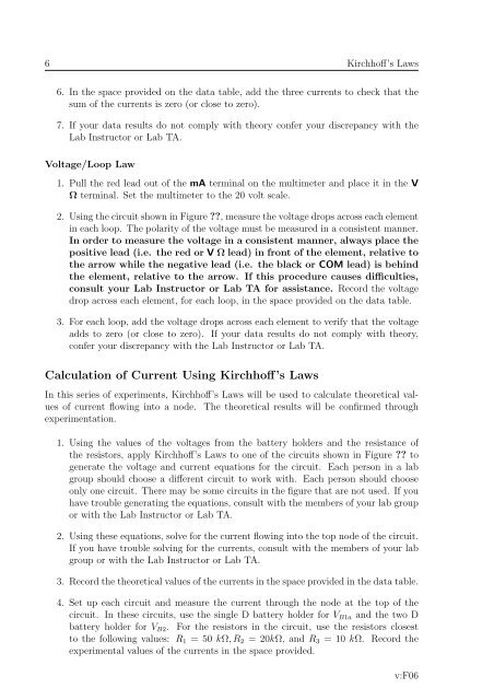
6 Kirchhoff’s <strong>Laws</strong>6. In the space provided on the data table, add the three currents to check that thesum of the currents is zero (or close to zero).7. If your data results do not comply with theory confer your discrepancy with theLab Instructor or Lab TA.Voltage/Loop Law1. Pull the red lead out of the mA terminal on the multimeter and place it in the VΩ terminal. Set the multimeter to the 20 volt scale.2. Using the circuit shown in Figure ??, measure the voltage drops across each elementin each loop. The polarity of the voltage must be measured in a consistent manner.In order to measure the voltage in a consistent manner, always place thepositive lead (i.e. the red or V Ω lead) in front of the element, relative tothe arrow while the negative lead (i.e. the black or COM lead) is behindthe element, relative to the arrow. If this procedure causes difficulties,consult your Lab Instructor or Lab TA for assistance. Record the voltagedrop across each element, for each loop, in the space provided on the data table.3. For each loop, add the voltage drops across each element to verify that the voltageadds to zero (or close to zero). If your data results do not comply with theory,confer your discrepancy with the Lab Instructor or Lab TA.Calculation of Current Using Kirchhoff’s <strong>Laws</strong>In this series of experiments, Kirchhoff’s <strong>Laws</strong> will be used to calculate theoretical valuesof current flowing into a node. The theoretical results will be confirmed throughexperimentation.1. Using the values of the voltages from the battery holders and the resistance ofthe resistors, apply Kirchhoff’s <strong>Laws</strong> to one of the circuits shown in Figure ?? togenerate the voltage and current equations for the circuit. Each person in a labgroup should choose a different circuit to work with. Each person should chooseonly one circuit. There may be some circuits in the figure that are not used. If youhave trouble generating the equations, consult with the members of your lab groupor with the Lab Instructor or Lab TA.2. Using these equations, solve for the current flowing into the top node of the circuit.If you have trouble solving for the currents, consult with the members of your labgroup or with the Lab Instructor or Lab TA.3. Record the theoretical values of the currents in the space provided in the data table.4. Set up each circuit and measure the current through the node at the top of thecircuit. In these circuits, use the single D battery holder for V B1a and the two Dbattery holder for V B2 . For the resistors in the circuit, use the resistors closestto the following values: R 1 = 50 kΩ, R 2 = 20kΩ, and R 3 = 10 kΩ. Record theexperimental values of the currents in the space provided.v:F06