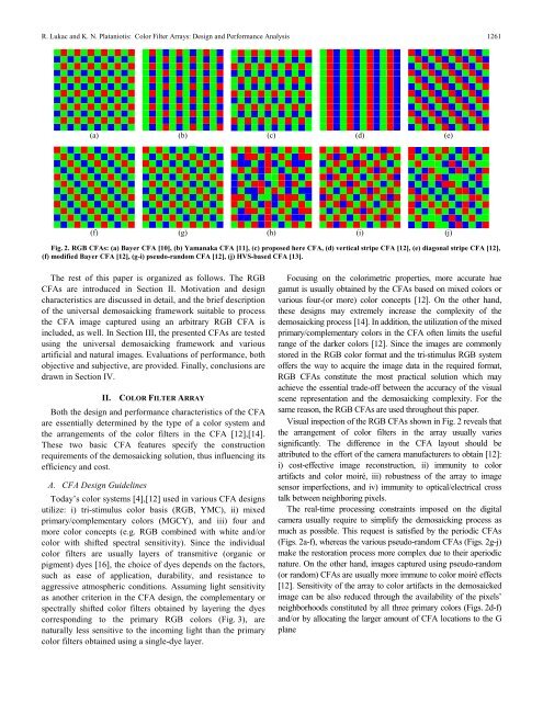
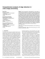
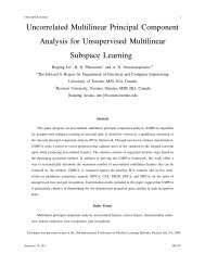
R. Lukac <strong>and</strong> K. N. Plataniotis: <strong>Color</strong> <strong>Filter</strong> <strong>Arrays</strong>: <strong>Design</strong> <strong>and</strong> <strong>Performance</strong> <strong>Analysis</strong> 1261(a) (b) (c) (d) (e)(f) (g) (h) (i) (j)Fig. 2. RGB CFAs: (a) Bayer CFA [10], (b) Yamanaka CFA [11], (c) proposed here CFA, (d) vertical stripe CFA [12], (e) diagonal stripe CFA [12],(f) modified Bayer CFA [12], (g-i) pseudo-r<strong>and</strong>om CFA [12], (j) HVS-based CFA [13].The rest of this paper is organized as follows. The RGBCFAs are introduced in Section II. Motivation <strong>and</strong> designcharacteristics are discussed in detail, <strong>and</strong> the brief descriptionof the universal demosaicking framework suitable to processthe CFA image captured using an arbitrary RGB CFA isincluded, as well. In Section III, the presented CFAs are testedusing the universal demosaicking framework <strong>and</strong> variousartificial <strong>and</strong> natural images. Evaluations of performance, bothobjective <strong>and</strong> subjective, are provided. Finally, conclusions aredrawn in Section IV.II. COLOR FILTER ARRAYBoth the design <strong>and</strong> performance characteristics of the CFAare essentially determined by the type of a color system <strong>and</strong>the arrangements of the color filters in the CFA [12],[14].These two basic CFA features specify the constructionrequirements of the demosaicking solution, thus influencing itsefficiency <strong>and</strong> cost.A. CFA <strong>Design</strong> GuidelinesToday’s color systems [4],[12] used in various CFA designsutilize: i) tri-stimulus color basis (RGB, YMC), ii) mixedprimary/complementary colors (MGCY), <strong>and</strong> iii) four <strong>and</strong>more color concepts (e.g. RGB combined with white <strong>and</strong>/orcolor with shifted spectral sensitivity). Since the individualcolor filters are usually layers of transmitive (organic orpigment) dyes [16], the choice of dyes depends on the factors,such as ease of application, durability, <strong>and</strong> resistance toaggressive atmospheric conditions. Assuming light sensitivityas another criterion in the CFA design, the complementary orspectrally shifted color filters obtained by layering the dyescorresponding to the primary RGB colors (Fig. 3), arenaturally less sensitive to the incoming light than the primarycolor filters obtained using a single-dye layer.Focusing on the colorimetric properties, more accurate huegamut is usually obtained by the CFAs based on mixed colors orvarious four-(or more) color concepts [12]. On the other h<strong>and</strong>,these designs may extremely increase the complexity of thedemosaicking process [14]. In addition, the utilization of the mixedprimary/complementary colors in the CFA often limits the usefulrange of the darker colors [12]. Since the images are commonlystored in the RGB color format <strong>and</strong> the tri-stimulus RGB systemoffers the way to acquire the image data in the required format,RGB CFAs constitute the most practical solution which mayachieve the essential trade-off between the accuracy of the visualscene representation <strong>and</strong> the demosaicking complexity. For thesame reason, the RGB CFAs are used throughout this paper.Visual inspection of the RGB CFAs shown in Fig. 2 reveals thatthe arrangement of color filters in the array usually variessignificantly. The difference in the CFA layout should beattributed to the effort of the camera manufacturers to obtain [12]:i) cost-effective image reconstruction, ii) immunity to colorartifacts <strong>and</strong> color moiré, iii) robustness of the array to imagesensor imperfections, <strong>and</strong> iv) immunity to optical/electrical crosstalk between neighboring pixels.The real-time processing constraints imposed on the digitalcamera usually require to simplify the demosaicking process asmuch as possible. This request is satisfied by the periodic CFAs(Figs. 2a-f), whereas the various pseudo-r<strong>and</strong>om CFAs (Figs. 2g-j)make the restoration process more complex due to their aperiodicnature. On the other h<strong>and</strong>, images captured using pseudo-r<strong>and</strong>om(or r<strong>and</strong>om) CFAs are usually more immune to color moiré effects[12]. Sensitivity of the array to color artifacts in the demosaickedimage can be also reduced through the availability of the pixels’neighborhoods constituted by all three primary colors (Figs. 2d-f)<strong>and</strong>/or by allocating the larger amount of CFA locations to the Gplane
1262IEEE Transactions on Consumer Electronics, Vol. 51, No. 4, NOVEMBER 2005BlackMagentaRedYellow(a)zdimageinterpolationdemosaicking stepxWhite(b)BlueCyanGreenESMSMESMSMFig. 3. Additive color mixing concept. Any spectrally shifted color canbe obtained using the different amount of the three RGB primary colors.zdimageinterpolationdemosaicking stepimageinterpolationpostprocessing stepx(Figs. 2a-c,g,i,j). Since the frequency of the G color b<strong>and</strong> is closeto the peak of the human luminance frequency response [17],[18],privileging the G color filters in the CFA layout improves theperceived sharpness of the captured image.Image sensor imperfections are usually observed along rows orcolumns of the sensor cells <strong>and</strong> thus, the CFAs shown in Figs. 2e,fshould avoid the visual impairments resulting from the sensordefects. Immunity to optical/electrical cross talk betweenneighboring pixels can be increased by creating the CFA with thefixed number of neighbors corresponding to each of the threeprimary colors. This request is even more important due to the factthat diagonally located neighbors have a lower cross-talkcontribution than the vertically or horizontally located neighbors[12], making the CFAs shown in Figs. 2g-j the worst solutions interms of this criterion.Since no CFA satisfies all design conditions, manufacturersusually select the CFA layout according to the type <strong>and</strong> resolutionof the image sensor, camera optical system, image processingcapabilities of the device, <strong>and</strong> the intended application. However,once the CFA layout is selected to acquire the CFA image data, thevisual quality of the demosaicked full-color image depends on theability of the demosaicking solution to overcome various spatial,structural <strong>and</strong> spectral constraints imposed on the single-sensordevice during the image formation <strong>and</strong> color reconstruction.B. Universal Demosaicking FrameworkThe acquired CFA image is a K1× K2gray-scale mosaic-like2image z : Z → Z with the single scalar value z ( rs , )located ateach spatial location (,). rs Operating along the row <strong>and</strong> columncoordinates r = 1, 2,..., K1<strong>and</strong> s = 1,2,..., K2, respectively, theinformation about the R ( k = 1) , G ( k = 2) , or B ( k = 3) colorfilters in the CFA can be stored using the location flags d ( rsk , )obtained either from the CFA layout or using the TIFF-EP storageformat [14]. Following the dimensions of the CFA image z , a2 3K1× K2vectorial field d : Z → Z of the correspondinglocation flags d( rsk , )is initialized using the default value d( rsk , )= 1to indicate the presence of the k -th color filter at the sensorlocation (,), rs <strong>and</strong> using the flags set to d ( rsk , )= 0 in all othercases.Fig. 4. Two basic solutions designed within the universaldemosaicking framework [14]: (a) non-adaptive component-wisesolution, (b) edge-sensing spectral model based solution with thepostprocessor.The CFA image z is used as the input to a demosaickingsolution which performs spectral interpolation [9] to obtain a2 3K1× K2demosaicked full-color image x : Z → Z . Thedemosaicking process starts by re-arranging the CFA image(Fig. 1a) to its color variant (Fig. 1b). Using the location flagsd( rsk , ), the scalar CFA image data z ( rs , )are transformed to thecorresponding vectorial representation x (,) rs= [ x (,) rsk, x (,) rsk, x (,) rsk]withx( rsk , )denoting the intensity in the R ( k = 1) , G ( k = 2) , or B( k = 3) channel of the color image x . Thus, the process producesthe color vector x ( rs , )= [ z ( rs , ),0,0] for d ( rs , )1= 1, x( rs , )= [0, z( rs , ),0]for d( rs , )2= 1, <strong>and</strong> x ( rs , )= [0,0, z ( rs , )] for d ( rs , )3= 1. Given thelocation flags d ( rsk , )= 0 denoting the missing components inx( rs , ), the corresponding values of x ( rsk , )are set equal to zero todenote their portion to the coloration of the color image x shownin Fig. 1b.To produce a full-color image (Fig. 1c), the missingcomponents are estimated at each spatial location (,) rs from theavailable neighboring components using the concept of imageinterpolation [9]. Using a 3× 3 sliding window instead of thespecialized shape masks known from the Bayer CFA-baseddemosaicking solutions (e.g. [1],[4],[6]-[8],[15]-[22]), theuniversal demosaicking framework [14] is directly applicable to anarbitrary CFA shown in Fig. 2. By localizing the flags d ( rsk , )= 0used to indicate the spatial location (,) rs in the k -th colorchannel to be demosaicked <strong>and</strong> utilizing the control mechanism toprevent from operating in areas which lack adequate inputinformation, the framework obtains the essential flexibility <strong>and</strong>independence from the CFA layout. In addition, the frameworkoffers a number of design <strong>and</strong> processing options to demosaick theacquired CFA data, ranging from the cost-effective non-adaptivecomponent-wise solutions (Fig. 4a) to sophisticated solutions(Fig. 4b) which use the edge-sensing mechanism (ESM), thespectral model (SM) <strong>and</strong> the postprocessor to produce thedemosaicked image pleasing for viewing. The interested readercan find the detailed description of the universal demosaickingframework <strong>and</strong> the two considered here solutions (Fig. 4) in [14].