Color Filter Arrays: Design and Performance Analysis - Multimedia ...
Color Filter Arrays: Design and Performance Analysis - Multimedia ...
Color Filter Arrays: Design and Performance Analysis - Multimedia ...

You also want an ePaper? Increase the reach of your titles
YUMPU automatically turns print PDFs into web optimized ePapers that Google loves.
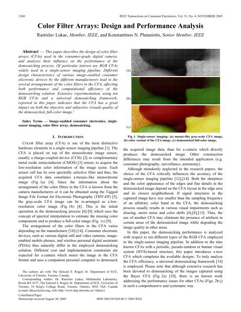
1260IEEE Transactions on Consumer Electronics, Vol. 51, No. 4, NOVEMBER 2005<strong>Color</strong> <strong>Filter</strong> <strong>Arrays</strong>: <strong>Design</strong> <strong>and</strong> <strong>Performance</strong> <strong>Analysis</strong>Rastislav Lukac, Member, IEEE, <strong>and</strong> Konstantinos N. Plataniotis, Senior Member, IEEEAbstract — This paper describes the design of color filterarrays (CFAs) used in the consumer-grade digital camera,<strong>and</strong> analyses their influence on the performance of thedemosaicking process. Of particular interest are RGB CFAswidely used in a single-sensor imaging pipeline. Differentdesign characteristics of various image-enabled consumerelectronic devices by the different manufacturers lead to theseveral arrangements of the color filters in the CFA, affectingboth performance <strong>and</strong> computational efficiency of thedemosaicking solution. Extensive experimentation, using tenRGB CFAs <strong>and</strong> a universal demosaicking framework,reported in this paper indicates that the CFA has a greatimpact on both the objective <strong>and</strong> subjective (visual) quality ofthe demosaicked, full-color image. 1Index Terms — Image-enabled consumer electronics, singlesensorimaging, color filter array, demosaicking.(a)(b)(c)I. INTRODUCTIONCOLOR filter array (CFA) is one of the most distinctivehardware elements in a single-sensor imaging pipeline [1]. TheCFA is placed on top of the monochrome image sensor,usually a charge-coupled device (CCD) [2] or complementarymetal oxide semiconductor (CMOS) [3] sensor, to acquire thelow-resolution color information of the image scene. Eachsensor cell has its own spectrally selective filter <strong>and</strong> thus, theacquired CFA data constitutes a mosaic-like monochromeimage (Fig. 1a) [4]. Since the information about thearrangement of the color filters in the CFA is known from thecamera manufacturers or it can be obtained using the TaggedImage File Format for Electronic Photography (TIFF-EP) [5],the gray-scale CFA image can be re-arranged as a lowresolutioncolor image (Fig. 1b) [4]. This is the initialoperation in the demosaicking process [6]-[8] which uses theconcept of spectral interpolation to estimate the missing colorcomponents <strong>and</strong> to produce a full-color image (Fig. 1c) [9].The arrangement of the color filters in the CFA variesdepending on the manufacturer [10]-[14]. Consumer electronicdevices, such as various digital still <strong>and</strong> video cameras, imageenabledmobile phones, <strong>and</strong> wireless personal digital assistants(PDAs) thus naturally differ in the employed demosaickingsolution. Different cost <strong>and</strong> implementation constraints areexpected for a camera which stores the image in the CFAformat <strong>and</strong> uses a companion personal computer to demosaickThe authors are with The Edward S. Rogers Sr. Department of ECE,University of Toronto, Toronto, Canada.Corresponding Author: Dr. Rastislav Lukac, <strong>Multimedia</strong> Laboratory,Room BA 4157, The Edward S. Rogers Sr. Department of ECE, University ofToronto, 10 King's College Road, Toronto, Ontario, M5S 3G4, Canada(e-mail: lukacr@ieee.org, web: http://www.dsp.utoronto.ca/~lukacr)Contributed PaperManuscript received August 30, 20050098 3063/05/$20.00 © 2005 IEEEFig. 1. Single-sensor imaging: (a) mosaic-like gray-scale CFA image,(b) color variant of the CFA image, (c) demosaicked full-color image.the acquired image data, than for a camera which directlyproduces the demosaicked image. Other constructiondifferences may result from the intended application (e.g.consumer photography, surveillance, astronomy).Although mistakenly neglected in the research papers, thechoice of the CFA critically influences the accuracy of thesingle-sensor imaging pipeline [12],[14]. Both the sharpness<strong>and</strong> the color appearance of the edges <strong>and</strong> fine details in thedemosaicked image depend on the CFA layout in the edge area<strong>and</strong> its closest neighborhood. If signal structures in thecaptured image have size smaller than the sampling frequencyof an arbitrary color b<strong>and</strong> in the CFA, the demosaickingprocess usually results in various visual impairments such asaliasing, moire noise <strong>and</strong> color shifts [4],[8],[15]. Thus, theuse of another CFA may eliminate the presence of artifacts incertain areas of the demosaicked image while degrading theimage quality in other areas.In this paper, the demosaicking performance is analyzedwith respect to ten different types of the RGB CFA employedin the single-sensor imaging pipeline. In addition to the nineknown CFAs with a periodic, pseudo-r<strong>and</strong>om or human visualsystem (HVS)-based structure, this paper introduces a newCFA which completes the available designs. To truly analyzethe CFA efficiency, a universal demosaicking framework [14]is employed. Please note that although extensive research hasbeen devoted to demosaicking of the images captured usingthe Bayer CFA (Fig. 2a) [10], there is no known workaddressing the performance issues for other CFAs (Figs. 2b-j)in such a comprehensive <strong>and</strong> systematic way.
R. Lukac <strong>and</strong> K. N. Plataniotis: <strong>Color</strong> <strong>Filter</strong> <strong>Arrays</strong>: <strong>Design</strong> <strong>and</strong> <strong>Performance</strong> <strong>Analysis</strong> 1261(a) (b) (c) (d) (e)(f) (g) (h) (i) (j)Fig. 2. RGB CFAs: (a) Bayer CFA [10], (b) Yamanaka CFA [11], (c) proposed here CFA, (d) vertical stripe CFA [12], (e) diagonal stripe CFA [12],(f) modified Bayer CFA [12], (g-i) pseudo-r<strong>and</strong>om CFA [12], (j) HVS-based CFA [13].The rest of this paper is organized as follows. The RGBCFAs are introduced in Section II. Motivation <strong>and</strong> designcharacteristics are discussed in detail, <strong>and</strong> the brief descriptionof the universal demosaicking framework suitable to processthe CFA image captured using an arbitrary RGB CFA isincluded, as well. In Section III, the presented CFAs are testedusing the universal demosaicking framework <strong>and</strong> variousartificial <strong>and</strong> natural images. Evaluations of performance, bothobjective <strong>and</strong> subjective, are provided. Finally, conclusions aredrawn in Section IV.II. COLOR FILTER ARRAYBoth the design <strong>and</strong> performance characteristics of the CFAare essentially determined by the type of a color system <strong>and</strong>the arrangements of the color filters in the CFA [12],[14].These two basic CFA features specify the constructionrequirements of the demosaicking solution, thus influencing itsefficiency <strong>and</strong> cost.A. CFA <strong>Design</strong> GuidelinesToday’s color systems [4],[12] used in various CFA designsutilize: i) tri-stimulus color basis (RGB, YMC), ii) mixedprimary/complementary colors (MGCY), <strong>and</strong> iii) four <strong>and</strong>more color concepts (e.g. RGB combined with white <strong>and</strong>/orcolor with shifted spectral sensitivity). Since the individualcolor filters are usually layers of transmitive (organic orpigment) dyes [16], the choice of dyes depends on the factors,such as ease of application, durability, <strong>and</strong> resistance toaggressive atmospheric conditions. Assuming light sensitivityas another criterion in the CFA design, the complementary orspectrally shifted color filters obtained by layering the dyescorresponding to the primary RGB colors (Fig. 3), arenaturally less sensitive to the incoming light than the primarycolor filters obtained using a single-dye layer.Focusing on the colorimetric properties, more accurate huegamut is usually obtained by the CFAs based on mixed colors orvarious four-(or more) color concepts [12]. On the other h<strong>and</strong>,these designs may extremely increase the complexity of thedemosaicking process [14]. In addition, the utilization of the mixedprimary/complementary colors in the CFA often limits the usefulrange of the darker colors [12]. Since the images are commonlystored in the RGB color format <strong>and</strong> the tri-stimulus RGB systemoffers the way to acquire the image data in the required format,RGB CFAs constitute the most practical solution which mayachieve the essential trade-off between the accuracy of the visualscene representation <strong>and</strong> the demosaicking complexity. For thesame reason, the RGB CFAs are used throughout this paper.Visual inspection of the RGB CFAs shown in Fig. 2 reveals thatthe arrangement of color filters in the array usually variessignificantly. The difference in the CFA layout should beattributed to the effort of the camera manufacturers to obtain [12]:i) cost-effective image reconstruction, ii) immunity to colorartifacts <strong>and</strong> color moiré, iii) robustness of the array to imagesensor imperfections, <strong>and</strong> iv) immunity to optical/electrical crosstalk between neighboring pixels.The real-time processing constraints imposed on the digitalcamera usually require to simplify the demosaicking process asmuch as possible. This request is satisfied by the periodic CFAs(Figs. 2a-f), whereas the various pseudo-r<strong>and</strong>om CFAs (Figs. 2g-j)make the restoration process more complex due to their aperiodicnature. On the other h<strong>and</strong>, images captured using pseudo-r<strong>and</strong>om(or r<strong>and</strong>om) CFAs are usually more immune to color moiré effects[12]. Sensitivity of the array to color artifacts in the demosaickedimage can be also reduced through the availability of the pixels’neighborhoods constituted by all three primary colors (Figs. 2d-f)<strong>and</strong>/or by allocating the larger amount of CFA locations to the Gplane
1262IEEE Transactions on Consumer Electronics, Vol. 51, No. 4, NOVEMBER 2005BlackMagentaRedYellow(a)zdimageinterpolationdemosaicking stepxWhite(b)BlueCyanGreenESMSMESMSMFig. 3. Additive color mixing concept. Any spectrally shifted color canbe obtained using the different amount of the three RGB primary colors.zdimageinterpolationdemosaicking stepimageinterpolationpostprocessing stepx(Figs. 2a-c,g,i,j). Since the frequency of the G color b<strong>and</strong> is closeto the peak of the human luminance frequency response [17],[18],privileging the G color filters in the CFA layout improves theperceived sharpness of the captured image.Image sensor imperfections are usually observed along rows orcolumns of the sensor cells <strong>and</strong> thus, the CFAs shown in Figs. 2e,fshould avoid the visual impairments resulting from the sensordefects. Immunity to optical/electrical cross talk betweenneighboring pixels can be increased by creating the CFA with thefixed number of neighbors corresponding to each of the threeprimary colors. This request is even more important due to the factthat diagonally located neighbors have a lower cross-talkcontribution than the vertically or horizontally located neighbors[12], making the CFAs shown in Figs. 2g-j the worst solutions interms of this criterion.Since no CFA satisfies all design conditions, manufacturersusually select the CFA layout according to the type <strong>and</strong> resolutionof the image sensor, camera optical system, image processingcapabilities of the device, <strong>and</strong> the intended application. However,once the CFA layout is selected to acquire the CFA image data, thevisual quality of the demosaicked full-color image depends on theability of the demosaicking solution to overcome various spatial,structural <strong>and</strong> spectral constraints imposed on the single-sensordevice during the image formation <strong>and</strong> color reconstruction.B. Universal Demosaicking FrameworkThe acquired CFA image is a K1× K2gray-scale mosaic-like2image z : Z → Z with the single scalar value z ( rs , )located ateach spatial location (,). rs Operating along the row <strong>and</strong> columncoordinates r = 1, 2,..., K1<strong>and</strong> s = 1,2,..., K2, respectively, theinformation about the R ( k = 1) , G ( k = 2) , or B ( k = 3) colorfilters in the CFA can be stored using the location flags d ( rsk , )obtained either from the CFA layout or using the TIFF-EP storageformat [14]. Following the dimensions of the CFA image z , a2 3K1× K2vectorial field d : Z → Z of the correspondinglocation flags d( rsk , )is initialized using the default value d( rsk , )= 1to indicate the presence of the k -th color filter at the sensorlocation (,), rs <strong>and</strong> using the flags set to d ( rsk , )= 0 in all othercases.Fig. 4. Two basic solutions designed within the universaldemosaicking framework [14]: (a) non-adaptive component-wisesolution, (b) edge-sensing spectral model based solution with thepostprocessor.The CFA image z is used as the input to a demosaickingsolution which performs spectral interpolation [9] to obtain a2 3K1× K2demosaicked full-color image x : Z → Z . Thedemosaicking process starts by re-arranging the CFA image(Fig. 1a) to its color variant (Fig. 1b). Using the location flagsd( rsk , ), the scalar CFA image data z ( rs , )are transformed to thecorresponding vectorial representation x (,) rs= [ x (,) rsk, x (,) rsk, x (,) rsk]withx( rsk , )denoting the intensity in the R ( k = 1) , G ( k = 2) , or B( k = 3) channel of the color image x . Thus, the process producesthe color vector x ( rs , )= [ z ( rs , ),0,0] for d ( rs , )1= 1, x( rs , )= [0, z( rs , ),0]for d( rs , )2= 1, <strong>and</strong> x ( rs , )= [0,0, z ( rs , )] for d ( rs , )3= 1. Given thelocation flags d ( rsk , )= 0 denoting the missing components inx( rs , ), the corresponding values of x ( rsk , )are set equal to zero todenote their portion to the coloration of the color image x shownin Fig. 1b.To produce a full-color image (Fig. 1c), the missingcomponents are estimated at each spatial location (,) rs from theavailable neighboring components using the concept of imageinterpolation [9]. Using a 3× 3 sliding window instead of thespecialized shape masks known from the Bayer CFA-baseddemosaicking solutions (e.g. [1],[4],[6]-[8],[15]-[22]), theuniversal demosaicking framework [14] is directly applicable to anarbitrary CFA shown in Fig. 2. By localizing the flags d ( rsk , )= 0used to indicate the spatial location (,) rs in the k -th colorchannel to be demosaicked <strong>and</strong> utilizing the control mechanism toprevent from operating in areas which lack adequate inputinformation, the framework obtains the essential flexibility <strong>and</strong>independence from the CFA layout. In addition, the frameworkoffers a number of design <strong>and</strong> processing options to demosaick theacquired CFA data, ranging from the cost-effective non-adaptivecomponent-wise solutions (Fig. 4a) to sophisticated solutions(Fig. 4b) which use the edge-sensing mechanism (ESM), thespectral model (SM) <strong>and</strong> the postprocessor to produce thedemosaicked image pleasing for viewing. The interested readercan find the detailed description of the universal demosaickingframework <strong>and</strong> the two considered here solutions (Fig. 4) in [14].
R. Lukac <strong>and</strong> K. N. Plataniotis: <strong>Color</strong> <strong>Filter</strong> <strong>Arrays</strong>: <strong>Design</strong> <strong>and</strong> <strong>Performance</strong> <strong>Analysis</strong> 1263original imagesensor CFA dataK 1CFA sampling(Fig. 2)K 2(Fig. 4)demosaicking(a) (b)processing errorFig. 6. Evaluation procedure.restored image(c) (d)Fig. 5. Test images: (a) CZP, (b) Lighthouse, (c) Parrots, (d) Rafting.III. EXPERIMENTAL RESULTSTo determine the performance of the CFAs listed in Fig. 2, anumber of test images have been utilized. Examples such asthe 512× 512 artificial CZP image (Fig. 5a) <strong>and</strong> the 512×512natural color images Lighthouse (Fig. 5b), Parrots (Fig. 5c)<strong>and</strong> Rafting (Fig. 5d) are used to emulate the applicationscenario. The test color images, which vary in both thecomplexity of the structural content (edges, fine details) <strong>and</strong>the color appearance, have been captured using three-sensordevices <strong>and</strong> normalized to 8-bit per channel RGBrepresentation. Following the evaluation procedure depicted inFig. 6, tests were performed by sampling the original images(Fig. 5) with each of the CFAs shown in Fig. 2 to obtain aCFA image z . Thus, the CFA image data z ( rs , )is given byz( rs , )= o( rs , )1for d( rs , )1= 1, z( rs , )= o( rs , )2for d ( rs , )2= 1, <strong>and</strong>z( rs , )= o( rs , )3for d ( rs , )3= 1, where d ( rsk , )denotes the locationflags corresponding to the k -th color channel <strong>and</strong> o ( rsk , )denotes the R ( k = 1) , G ( k = 2) <strong>and</strong> B ( k = 3) component ofthe original color pixel o (,) rs= [ o (,)1 rs, o (,)2 rs, o (,)3 rs] occupying thelocation (,) rs, with r= 1,2,..., K1<strong>and</strong> s = 1,2,..., K2.Using thetwo demosaicking solutions shown in Fig. 4, the demosaickedimage x is generated by applying the universal demosaickingframework [14] onto the CFA image z . To evaluate theperformance of the considered CFAs (Fig. 2), image qualitywas measured by comparing the original color image to thedemosaicked image. To facilitate the objective comparisons,the RGB color space based mean absolute error (MAE) <strong>and</strong>mean square error (MSE) criteria, <strong>and</strong> the CIE-LUV colorspace based normalized color difference (NCD) criterion areused in this work. The interested reader can find the definitionsof the above-listed criteria in [4].Demosaicking results reported in Tables I <strong>and</strong> II show thatthe use of the diagonal stripe CFA (Fig. 2e) provides the bestperformance for the cost-effective demosaicking solution.Other CFAs suitable for this variant of the universaldemosaicking framework are some of the periodic (Figs. 2a,c)<strong>and</strong> pseudo-r<strong>and</strong>om (Figs. 2g,i) CFAs. In the case of thesophisticated demosaicking solution, the Bayer (Fig. 2a),proposed here (Fig. 2c), diagonal stripe (Fig. 2e) <strong>and</strong> pseudor<strong>and</strong>om(Fig. 2g) CFA outperform other CFAs. Simpleinspection of the results corresponding respectively to the costeffective(Table 1) <strong>and</strong> the sophisticated (Table 2)demosaicking solution shows an improvement obtainedthrough the utilization of the edge-sensing mechanism, spectralmodel <strong>and</strong> the postprocessor during the processing.Fig. 7 <strong>and</strong> Fig. 8 demonstrate the ability (or its lack) of boththe CFA <strong>and</strong> the demosaicking solution to preserve variousimage frequencies. As shown in Fig. 7, each of the CFAsresulted in aliasing effects <strong>and</strong> color artifacts. For example, theimages obtained using the CFAs shown in Figs. 2a,g,h,j sufferfrom aliasing in the horizontal, vertical, <strong>and</strong> diagonaldirection. The use of the CFAs shown in Figs. 2b,d producedaliasing artifacts mainly in the horizontal direction, whereasCFAs in Figs. 2e,f,i <strong>and</strong> Fig. 2c resulted in aliasing mostlyobserved in the diagonal <strong>and</strong> vertical direction, respectively.By replacing the cost-effective demosaicked solution with itssophisticated variant, aliasing can be significantly reduced, ifnot removed altogether using some CFAs (Figs. 8a-c,i).Fig. 9 <strong>and</strong> Fig. 10 depict enlarged parts of the natural colorimages cropped in areas with significant structural contents.Visual inspection of the demosaicked images reveals that theperformance highly depends on the orientation <strong>and</strong> size of theedges <strong>and</strong> fine details in the area under consideration, <strong>and</strong> thatthe choice of the CFA plays an important role in obtaining therequired visual quality. For example, although the costeffectivedemosaicking solution was used, the complex fencearea in the image Lighthouse shown in Figs. 9c,e,f,i,j does notsuffer so much from aliasing, which is even present in theimages obtained using the sophisticated demosaicking solutioncombined with the well-known CFAs (Figs. 9a,b,d). In allcases shown in Figs. 9 <strong>and</strong> 10, images obtained using thesophisticated demosaicking solution show the enhanced colorappearance <strong>and</strong> image sharpness.
1264IEEE Transactions on Consumer Electronics, Vol. 51, No. 4, NOVEMBER 2005TABLE ICOMPARISON OF THE CFAS USING THE COST-EFFECTIVE DEMOSAICKING SOLUTION SHOWN IN FIG. 4AImage CZP (Fig. 5a) Lighthouse (Fig. 5b) Parrots (Fig. 5c) Rafting (Fig. 5d)CFA / Criterion MAE MSE NCD MAE MSE NCD MAE MSE NCD MAE MSE NCDFig. 2a 39.49 3457.7 0.8977 4.92 137.9 0.0580 2.21 32.8 0.0269 4.93 94.0 0.0750Fig. 2b 42.76 4005.7 0.9461 5.57 172.1 0.0655 2.38 37.7 0.0293 5.24 105.8 0.0801Fig. 2c 41.50 3815.5 0.9496 5.23 144.9 0.0615 2.32 37.7 0.0292 5.35 107.7 0.0840Fig. 2d 45.94 6430.3 1.2728 6.96 307.0 0.0983 3.14 68.0 0.0475 6.00 153.3 0.1109Fig. 2e 36.37 3314.7 0.8297 4.81 117.8 0.0545 2.14 30.2 0.0268 4.91 92.9 0.0772Fig. 2f 37.31 4330.0 0.9784 5.16 146.2 0.0653 2.42 43.9 0.0325 5.39 116.9 0.0906Fig. 2g 39.92 3671.8 0.9289 5.06 144.0 0.0606 2.22 34.2 0.0276 5.06 99.5 0.0788Fig. 2h 42.85 4524.8 1.0322 5.60 176.7 0.0698 2.50 45.5 0.0334 5.53 120.2 0.0913Fig. 2i 36.79 3670.1 0.9308 4.91 131.2 0.0642 2.27 35.6 0.0311 5.05 99.0 0.0869Fig. 2j 42.96 4545.2 1.0437 5.44 164.5 0.0679 2.54 47.6 0.0335 5.63 125.1 0.0923(o)(a)(b) (c) (d)(e) (f) (g)(h) (i) (j)Fig. 7. CZP image demosaicking using the cost-effective solution in Fig. 4a: (o) original image, (a-j) demosaicked images corresponding to the CFAsshown in Figs. 2a-j, respectively.
R. Lukac <strong>and</strong> K. N. Plataniotis: <strong>Color</strong> <strong>Filter</strong> <strong>Arrays</strong>: <strong>Design</strong> <strong>and</strong> <strong>Performance</strong> <strong>Analysis</strong> 1265TABLE IICOMPARISON OF THE CFAS USING THE SOPHISTICATED DEMOSAICKING SOLUTION SHOWN IN FIG. 4BImage CZP (Fig. 5a) Lighthouse (Fig. 5b) Parrots (Fig. 5c) Rafting (Fig. 5d)CFA / Criterion MAE MSE NCD MAE MSE NCD MAE MSE NCD MAE MSE NCDFig. 2a 2.37 33.9 0.1439 1.70 13.7 0.0230 1.17 5.5 0.0169 1.95 18.2 0.0350Fig. 2b 3.98 78.9 0.2252 2.16 24.4 0.0306 1.29 7.1 0.0182 2.20 23.0 0.0394Fig. 2c 3.32 69.1 0.1893 1.75 12.7 0.0247 1.24 6.5 0.0178 2.28 24.1 0.0412Fig. 2d 19.86 2375.3 0.5889 5.69 251.7 0.0773 2.81 48.2 0.0389 4.43 94.5 0.0782Fig. 2e 6.30 279.2 0.2368 1.76 12.3 0.0248 1.31 7.7 0.0182 2.43 25.7 0.0432Fig. 2f 5.26 180.9 0.2351 2.08 18.9 0.0282 1.43 10.7 0.0200 2.86 34.3 0.0494Fig. 2g 2.75 48.2 0.1705 1.87 15.3 0.0252 1.16 6.0 0.0167 2.15 21.2 0.0382Fig. 2h 8.24 372.4 0.3406 2.89 46.4 0.0392 1.57 13.0 0.0225 2.95 37.0 0.0527Fig. 2i 5.88 185.6 0.2658 2.13 19.7 0.0308 1.35 8.9 0.0198 2.60 27.6 0.0481Fig. 2j 6.24 220.6 0.2851 2.36 27.1 0.0322 1.58 13.0 0.0222 2.90 37.0 0.0507(o)(a)(b) (c) (d)(e) (f) (g)(h) (i) (j)Fig. 8. CZP image demosaicking using the sophisticated solution in Fig. 4b: (o) original image, (a-j) demosaicked images corresponding to the CFAsshown in Figs. 2a-j, respectively.
1266IEEE Transactions on Consumer Electronics, Vol. 51, No. 4, NOVEMBER 2005(o)(o)(a)(a)(b)(b)(c)(c)(d)(d)(e)(e)(f)(f)(g)(g)(h)(h)(i)(i)(j)Fig. 9. Lighthouse image demosaicking: (o) original image, (a-j)demosaicked images corresponding to the CFAs shown in Figs. 2a-j,respectively. Demosaicking was performed using: (left column) costeffectivesolution, (right column) sophisticated solution.Contributed Paper(j)Fig. 10. Parrots <strong>and</strong> Rafting image demosaicking: (o) original image,(a-j) demosaicked images corresponding to the CFAs shown in Figs. 2a-j,respectively. Demosaicking was performed using: (left column) costeffectivesolution, (right column) sophisticated solution.
R. Lukac <strong>and</strong> K. N. Plataniotis: <strong>Color</strong> <strong>Filter</strong> <strong>Arrays</strong>: <strong>Design</strong> <strong>and</strong> <strong>Performance</strong> <strong>Analysis</strong> 1267In the summary, the following conclusions can be drawn:i) the perfect CFA does not exist, ii) the choice of the CFAgreatly influences the performance of the single-sensorimaging pipeline, <strong>and</strong> iii) visual impairments can be reducedby changing the CFA <strong>and</strong>/or utilizing the sophisticateddemosaicking solution with the included postprocessor.IV. CONCLUSIONThis paper presented the design, analysis <strong>and</strong> performanceevaluation of the color filter array (CFA) which is the mostcrucial element in the single-sensor consumer electronicdevice used to capture the visual scene. Of particular interestwere RGB CFAs due to the relative simplicity of thedemosaicking process <strong>and</strong> the natural connection to thecommonly used RGB format for displaying <strong>and</strong> storage of thecaptured images. The universal demosaicking framework wasused to guide the performance evaluation of the ten RGBCFAs separately employed in the single-sensor imagingpipeline. Experimentation performed here suggests that thechoice of the CFA critically affects the amount of variousvisual impairments, such as color shifts, artifacts, <strong>and</strong> aliasingeffects, present in the demosaicked image.REFERENCES[1] K. Parulski <strong>and</strong> K. E. Spaulding, “<strong>Color</strong> image processing for digitalcameras,” in Digital <strong>Color</strong> Imaging H<strong>and</strong>book, (eds.) G. Sharma, CRCPress, Boca Raton, FL., pp. 728-757, 2002.[2] P. L. P. Dillon, D. M. Lewis, <strong>and</strong> F. G. Kaspar, “<strong>Color</strong> imaging systemusing a single CCD area array,” IEEE Journal of Solid-State Circuits,vol. 13, no. 1, pp. 28-33, February 1978.[3] T. Lule, S. Benthien, H. Keller, et al., “Sensitivity of CMOS basedimagers <strong>and</strong> scaling perspectives,” IEEE Transactions on ElectronDevices, vol. 47, no. 11, pp. 2110-2122, November 2000.[4] R. Lukac <strong>and</strong> K. N. Plataniotis, “Data-adaptive filters for demosaicking:A framework,” IEEE Transactions on Consumer Electronics, vol. 51,no. 2, pp.560-570, May 2005.[5] Technical Committee ISO/TC 42, Photography, “Electronic still pictureimaging - Removable memory, Part 2: Image data format - TIFF/EP,”ISO 12234-2, January 2001.[6] R. Lukac <strong>and</strong> K. N. Plataniotis, “ Fast video demosaicking solution formobile phone imaging applications,” IEEE Transactions on ConsumerElectronics, vol. 51, no. 2, pp. 675-681, May 2005.[7] X. Wu <strong>and</strong> N. Zhang, “Primary-consistant soft-decision colordemosaicking for digital cameras,” IEEE Transactions on ImageProcessing, vol. 13, no. 9, pp. 1263-1274, September 2004.[8] B. K. Gunturk, J. Glotzbach, Y. Altunbasak, R. W. Schaffer, <strong>and</strong>R. M. Murserau, “Demosaicking: color filter array interpolation,” IEEESignal Processing Magazine, vol. 22, no. 1, pp. 44-54, January 2005.[9] R. Lukac, B. Smolka, K. Martin, K. N. Plataniotis, <strong>and</strong> A. N.Venetsanopulos, ”Vector filtering for color imaging,” IEEE SignalProcessing Magazine; vol. 22, no. 1, pp. 74-86, January 2005.[10] B. E. Bayer, “<strong>Color</strong> imaging array,” U.S. Patent 3 971 065, July 1976.[11] S. Yamanaka, “Solid state camera,” U.S. Patent 4 054 906, Nov. 1977.[12] FillFactory, “Technology image sensor: the color filter array,” AvailableOnline: http://www.fillfactory.com/htm/technology/htm/rgbfaq.htm.[13] M. Parmar <strong>and</strong> S.J. Reeves, “A perceptually based design methodologyfor color filter arrays,” in Proc. IEEE Int. Con. Acoustics, Speech, <strong>and</strong>Signal Processing (ICASSP'04), vol. 3, pp. 473-476, May 2004.[14] R. Lukac <strong>and</strong> K. N. Plataniotis, “ Universal demosaicking for imagingpipelines with an RGB color filter array,” Pattern Recognition, vol. 38,no. 11, pp. 2208-2212, November 2005.[15] R. Lukac <strong>and</strong> K. N. Plataniotis, “Normalized color-ratio modeling forCFA interpolation,” IEEE Transactions on Consumer Electronics, vol.50, no. 2, pp. 737-745, May 2004.[16] J. Adams, K. Parulski, <strong>and</strong> K. Spaulding, “<strong>Color</strong> processing in digitalcameras,” IEEE Micro, vol. 18, no. 6, pp. 20-30, Nov./Dec. 1998.[17] R. Lukac, K. Martin, <strong>and</strong> K. N. Plataniotis, “Demosaicked image postprocessingusing local color ratios,” IEEE Transactions on Circuit <strong>and</strong>Systems for Video Technology, vol. 14, no. 6, pp. 914-920, June 2004.[18] S.C. Pei <strong>and</strong> I.K. Tam, “Effective color interpolation in CCD color filterarrays using signal correlation,” IEEE Trans. Circuits <strong>and</strong> Systems forVideo Technology, vol. 13, no. 6, pp. 503-513, June 2003.[19] W. Lu <strong>and</strong> Y. P. Tang, “<strong>Color</strong> filter array demosaicking: new method<strong>and</strong> performance measures,” IEEE Transactions on Image Processing,vol. 12, no. 10, pp. 1194-1210, October 2003.[20] R. Lukac, K. N. Plataniotis, D. Hatzinakos, <strong>and</strong> M. Aleksic, “A novelcost effective demosaicing approach,” IEEE Transactions on ConsumerElectronics, vol. 50, no. 1, pp. 256-261, February 2004.[21] D. Alleyson, S. Susstrunk <strong>and</strong> J. Herault, “Linear demosaicing inspiredby the human visual system,” IEEE Transactions on Image Processing,vol. 14, no. 4, pp. 439-449, April 2005.[22] N. Kehtarnavaz, H.J Oh, <strong>and</strong> Y. Yoo, “<strong>Color</strong> filter array interpolationusing color correlations <strong>and</strong> directional derivatives,” Journal ofElectronic Imaging, vol. 12, no. 4, pp. 621-632, October 2003.Rastislav Lukac received the M.S. (Ing.) <strong>and</strong> Ph.D.degrees in Telecommunications from the TechnicalUniversity of Kosice, Slovak Republic in 1998 <strong>and</strong>2001, respectively. From February 2001 to August 2002he was an Assistant Professor at the Department ofElectronics <strong>and</strong> <strong>Multimedia</strong> Communications at theTechnical University of Kosice. Since August 2002 he isa Researcher in Slovak Image Processing Center inDobsina, Slovak Republic. From January 2003 to March 2003 he was aPostdoctoral Fellow at the Artificial Intelligence & Information <strong>Analysis</strong> Labat the Aristotle University of Thessaloniki, Greece. Since May 2003 he hasbeen a Post-doctoral Fellow with the Edward S. Rogers Sr. Department ofElectrical <strong>and</strong> Computer Engineering at the University of Toronto in Toronto,Canada. His research interests include digital camera image processing,microarray image processing, multimedia security, <strong>and</strong> nonlinear filtering <strong>and</strong>analysis techniques for color image & video processing.Dr. Lukac is a Member of the IEEE Circuits <strong>and</strong> Systems, IEEE ConsumerElectronics, <strong>and</strong> IEEE Signal Processing Societies. He serves as a TechnicalReviewer for various scientific journals <strong>and</strong> he participates as a Member ofnumerous International Conference Committees. In 2003 he was awarded theNATO/NSERC Science Award.Konstantinos N. Plataniotis received the B.Engineering degree in Computer Engineering from theDepartment of Computer Engineering <strong>and</strong> Informatics,University of Patras, Patras, Greece in 1988 <strong>and</strong> the M.S<strong>and</strong> Ph.D degrees in Electrical Engineering from theFlorida Institute of Technology (Florida Tech),Melbourne, Florida in 1992 <strong>and</strong> 1994 respectively. FromAugust 1997 to June 1999 he was an Assistant Professorwith the School of Computer Science at Ryerson University. He is currentlyan Associate Professor at the Edward S. Rogers Sr. Department of Electrical& Computer Engineering where he researches <strong>and</strong> teaches image processing,adaptive systems, <strong>and</strong> multimedia signal processing. He co-authored, withA.N. Venetsanopoulos, a book on "<strong>Color</strong> Image Processing & Applications",Springer Verlag, May 2000, he is a contributor to seven books, <strong>and</strong> he haspublished more than 300 papers in refereed journals <strong>and</strong> conferenceproceedings in the areas of multimedia signal processing, image processing,adaptive systems, communications systems <strong>and</strong> stochastic estimation.Dr. Plataniotis is a Senior Member of IEEE, an Associate Editor for theIEEE Transactions on Neural Networks, a past member of the IEEE TechnicalCommittee on Neural Networks for Signal Processing. He was the TechnicalCo-Chair of the Canadian Conference on Electrical <strong>and</strong> ComputerEngineering (CCECE) 2001, <strong>and</strong> CCECE 2004. He is the Vice-chair of the2006 IEEE International Conference in <strong>Multimedia</strong> <strong>and</strong> Expo (ICME 2006),the Technical Program Co-chair for 2006 IEEE Intelligent TransportationSystems Conference (ITSC 2006), <strong>and</strong> the Image Processing Area Editor forthe IEEE Signal Processing Society e-letter.