Optimal Design and Fabrication of a Piezoactuated Flexure XYZ ...
Optimal Design and Fabrication of a Piezoactuated Flexure XYZ ...
Optimal Design and Fabrication of a Piezoactuated Flexure XYZ ...

You also want an ePaper? Increase the reach of your titles
YUMPU automatically turns print PDFs into web optimized ePapers that Google loves.
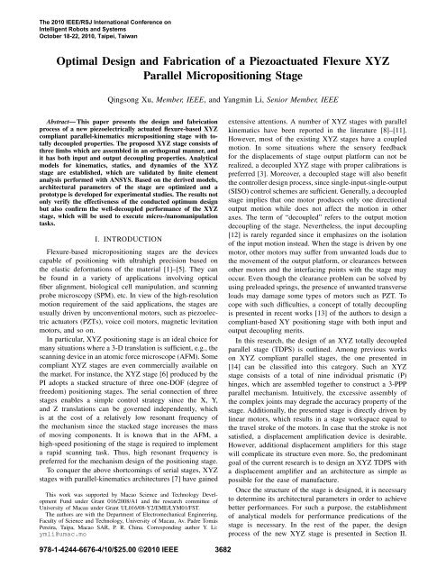
The 2010 IEEE/RSJ International Conference onIntelligent Robots <strong>and</strong> SystemsOctober 18-22, 2010, Taipei, Taiwan<strong>Optimal</strong> <strong>Design</strong> <strong>and</strong> <strong>Fabrication</strong> <strong>of</strong> a <strong>Piezoactuated</strong> <strong>Flexure</strong> <strong>XYZ</strong>Parallel Micropositioning StageQingsong Xu, Member, IEEE, <strong>and</strong> Yangmin Li, Senior Member, IEEEAbstract— This paper presents the design <strong>and</strong> fabricationprocess <strong>of</strong> a new piezoelectrically actuated flexure-based <strong>XYZ</strong>compliant parallel-kinematics micropositioning stage with totallydecoupled properties. The proposed <strong>XYZ</strong> stage consists <strong>of</strong>three limbs which are assembled in an orthogonal manner, <strong>and</strong>it has both input <strong>and</strong> output decoupling properties. Analyticalmodels for kinematics, statics, <strong>and</strong> dynamics <strong>of</strong> the <strong>XYZ</strong>stage are established, which are validated by finite elementanalysis performed with ANSYS. Based on the derived models,architectural parameters <strong>of</strong> the stage are optimized <strong>and</strong> aprototype is developed for experimental studies. The results notonly verify the effectiveness <strong>of</strong> the conducted optimum designbut also confirm the well-decoupled performance <strong>of</strong> the <strong>XYZ</strong>stage, which will be used to execute micro-/nanomanipulationtasks.I. INTRODUCTION<strong>Flexure</strong>-based micropositioning stages are the devicescapable <strong>of</strong> positioning with ultrahigh precision based onthe elastic deformations <strong>of</strong> the material [1]–[5]. They canbe found in a variety <strong>of</strong> applications involving opticalfiber alignment, biological cell manipulation, <strong>and</strong> scanningprobe microscopy (SPM), etc. In view <strong>of</strong> the high-resolutionmotion requirement <strong>of</strong> the said applications, the stages areusually driven by unconventional motors, such as piezoelectricactuators (PZTs), voice coil motors, magnetic levitationmotors, <strong>and</strong> so on.In particular, <strong>XYZ</strong> positioning stage is an ideal choice formany situations where a 3-D translation is sufficient, e.g., thescanning device in an atomic force microscope (AFM). Somecompliant <strong>XYZ</strong> stages are even commercially available onthe market. For instance, the <strong>XYZ</strong> stage [6] produced by thePI adopts a stacked structure <strong>of</strong> three one-DOF (degree <strong>of</strong>freedom) positioning stages. The serial connection <strong>of</strong> threestages enables a simple control strategy since the X, Y,<strong>and</strong> Z translations can be governed independently, whichis at the cost <strong>of</strong> a relatively low resonant frequency <strong>of</strong>the mechanism since the stacked stage increases the mass<strong>of</strong> moving components. It is known that in the AFM, ahigh-speed positioning <strong>of</strong> the stage is required to implementa rapid scanning task. Thus, high resonant frequency ispreferred for the mechanism design <strong>of</strong> the positioning stage.To conquer the above shortcomings <strong>of</strong> serial stages, <strong>XYZ</strong>stages with parallel-kinematics architectures [7] have gainedThis work was supported by Macao Science <strong>and</strong> Technology DevelopmentFund under Grant 016/2008/A1 <strong>and</strong> the research committee <strong>of</strong>University <strong>of</strong> Macau under Grant UL016/08-Y2/EME/LYM01/FST.The authors are with the Department <strong>of</strong> Electromechanical Engineering,Faculty <strong>of</strong> Science <strong>and</strong> Technology, University <strong>of</strong> Macau, Av. Padre TomásPereira, Taipa, Macao SAR, P. R. China. Corresponding author Y. Li:ymli@umac.moextensive attentions. A number <strong>of</strong> <strong>XYZ</strong> stages with parallelkinematics have been reported in the literature [8]–[11].However, most <strong>of</strong> the existing <strong>XYZ</strong> stages have a coupledmotion. In some situations where the sensory feedbackfor the displacements <strong>of</strong> stage output platform can not berealized, a decoupled <strong>XYZ</strong> stage with proper calibrations ispreferred [3]. Moreover, a decoupled stage will also benefitthe controller design process, since single-input-single-output(SISO) control schemes are sufficient. Generally, a decoupledstage implies that one motor produces only one directionaloutput motion while does not affect the motion in otheraxes. The term <strong>of</strong> “decoupled” refers to the output motiondecoupling <strong>of</strong> the stage. Nevertheless, the input decoupling[12] is rarely regarded since it emphasizes on the isolation<strong>of</strong> the input motion instead. When the stage is driven by onemotor, other motors may suffer from unwanted loads due tothe movement <strong>of</strong> the output platform, or clearances betweenother motors <strong>and</strong> the interfacing points with the stage mayoccur. Even though the clearance problem can be solved byusing preloaded springs, the presence <strong>of</strong> unwanted transverseloads may damage some types <strong>of</strong> motors such as PZT. Tocope with such difficulties, a concept <strong>of</strong> totally decouplingis presented in recent works [13] <strong>of</strong> the authors to design acompliant-based XY positioning stage with both input <strong>and</strong>output decoupling merits.In this research, the design <strong>of</strong> an <strong>XYZ</strong> totally decoupledparallel stage (TDPS) is outlined. Among previous workson <strong>XYZ</strong> compliant parallel stages, the one presented in[14] can be classified into this category. Such an <strong>XYZ</strong>stage consists <strong>of</strong> a total <strong>of</strong> nine individual prismatic (P)hinges, which are assembled together to construct a 3-PPPparallel mechanism. Intuitively, the excessive assembly <strong>of</strong>the complex joints may degrade the accuracy property <strong>of</strong> thestage. Additionally, the presented stage is directly driven bylinear motors, which results in a stage workspace equal tothe travel stroke <strong>of</strong> the motors. In case that the stroke is notsatisfied, a displacement amplification device is desirable.However, additional displacement amplifiers for this stagewill complicate its structure even more. So, the predominantgoal <strong>of</strong> the current research is to design an <strong>XYZ</strong> TDPS witha displacement amplifier <strong>and</strong> an architecture as simple aspossible for the ease <strong>of</strong> manufacture.Once the structure <strong>of</strong> the stage is designed, it is necessaryto determine its architectural parameters in order to achievebetter performances. For such a purpose, the establishment<strong>of</strong> analytical models for performance predications <strong>of</strong> thestage is necessary. In the rest <strong>of</strong> the paper, the designprocess <strong>of</strong> the new <strong>XYZ</strong> stage is presented in Section II.978-1-4244-6676-4/10/$25.00 ©2010 IEEE 3682
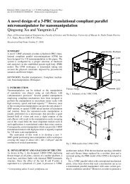
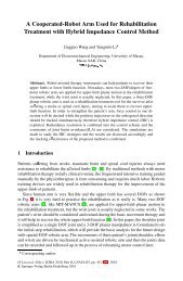
Fig. 1. (a) A compound bridge-type displacement amplifier with certaintolerance <strong>of</strong> lateral load; (b) a 2-DOF linear guiding mechanism using acompound parallelogram flexure; (c) a monolithic PPP limb with decoupledtranslations.(a)Limb 2Limb 1Output platform(b)zyLimb 3Fig. 2. (a) A two-layered PPP limb with decoupled translations; (b) adecoupled <strong>XYZ</strong> stage composed <strong>of</strong> three limbs.Then, mechanical modeling is carried out <strong>and</strong> validated withFEA in Sections III <strong>and</strong> IV, respectively. Afterwards, thedimension optimization <strong>of</strong> the stage is realized in Section V,<strong>and</strong> a prototype is fabricated for performance tests in SectionVI. Finally, Section VII concludes this paper.II. MECHANISM DESCRIPTION OF THE <strong>XYZ</strong>STAGEThe primary objective for the design <strong>of</strong> an <strong>XYZ</strong> stagewith decoupled output motion is to eliminate the cross-axiscoupling errors between the X, Y, <strong>and</strong> Z directional translations<strong>and</strong> the parasitic rotation errors around the axes. Onthe other h<strong>and</strong>, since the stage will be driven by three linearmotors, it is important to make sure that when one motordrives the stage to move along the pertinent axis, the motorbears neither transverse loads nor transverse displacementsinduced by the other two motors driving the stage along theremaining two axes.Specifically, the compound bridge-type displacement amplifier[see Fig. 1(a)] can provide both an amplified linearguiding output motion in the vertical direction (z-axis) <strong>and</strong>a spring preload for the linear actuator. Besides, this type <strong>of</strong>amplifier has much larger input stiffness <strong>and</strong> larger lateralstiffness than the conventional bridge-type amplifier. Thelarge input stiffness calls for an actuator with large blockingforce <strong>and</strong> stiffness. Hence, PZT is the most suitable actuatorfor the drives <strong>of</strong> the amplifier. On the other h<strong>and</strong>, thelarge lateral stiffness indicates that the output end <strong>of</strong> theamplifier can tolerate a large lateral load. This merit providesprotection for the inner PZT which can only tolerate smallxmagnitude <strong>of</strong> lateral load.In addition, by orthogonally adding a pair <strong>of</strong> flexure hingesto each leg <strong>of</strong> the conventional 1-D compound parallelogramflexure translational stage, a 2-D spatial stage is constructedas shown in Fig. 1(b). By imposing an external force F x ,the output stage displays a pure translation along the x-axisdue to the same length for the four R-R legs. Besides, byapplying a force F y <strong>and</strong> a moment M x to the output stage,the stage will produce a pure translation along the y-axis,while without cross-axis errors in neither x-axis nor z-axisdirection. It is noticeable that in an <strong>XYZ</strong> stage constructedlater, the additional moment M x for one limb mentionedabove is produced by the other two limbs constructing theoverall stage.Thus, by combining the preceding amplifier with the2-DOF linear guiding mechanism, a monolithic 3-D PPPlimb with decoupled translations is obtained as shown inFig. 1(c). Furthermore, for the ease <strong>of</strong> fabrications using suchprocesses as wire electrical discharge machining (EDM),the amplifier is attached to the PP limb in a two-layeredmanner as depicted in Fig. 2(a). This PPP limb can beemployed as a basic component to design an <strong>XYZ</strong> parallelstage with decoupled structure. For example, employing threesuch limbs, a totally decoupled <strong>XYZ</strong> stage is constructed asshown in Fig. 2(b), where the idea <strong>of</strong> orthogonal arrangement[14], [15] is adopted to assemble the three limbs together. Inaddition, the three limbs are assembled in such a way that theactuation axes <strong>of</strong> the limbs intersect at one common point.This assembly scheme is utilized to eliminate the unwantedinternal moments which will occur if the actuation axes donot intersect at one common point. Both the input decoupling<strong>and</strong> output decoupling properties are expected from the<strong>XYZ</strong> stage, <strong>and</strong> the stage performances are assessed in thefollowing discussions by establishing analytical models first.III. SYSTEM MODELINGThis section derives simple analytical models <strong>of</strong> the stagefor the evaluation <strong>of</strong> its amplification ratio, input stiffness,stress, <strong>and</strong> natural frequency, which can be used for theperformance assessment <strong>and</strong> cost-effective optimum design<strong>of</strong> the stage.A. Kinematics <strong>and</strong> Statics ModelingDue to a decoupled <strong>and</strong> parallel kinematics structure, theproperties in the three working axes <strong>of</strong> the <strong>XYZ</strong> stage areidentical in theory. Given the input displacements (d 1 , d 2 ,<strong>and</strong> d 3 ) <strong>of</strong> the three PZT actuators, the stage output motion(d x , d y , <strong>and</strong> d z ) <strong>and</strong> the actuator input forces (F 1 , F 2 , <strong>and</strong>F 3 ) can be calculated by the following kinematics <strong>and</strong> staticsequations:⎡⎣ d ⎤ ⎡xd y⎦ = ⎣ A ⎤⎡s 0 00 A s 0 ⎦⎣ d ⎤1d 2⎦, (1)d z 0 0 A s d 3⎡⎣ F ⎤ ⎡1F 2⎦ = ⎣ K ⎤⎡a 0 00 K a 0 ⎦⎣ d ⎤1d 2⎦, (2)F 3 0 0 K a d 33683
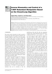
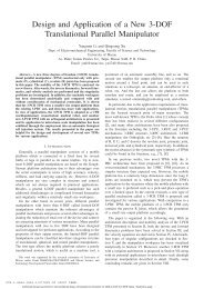
Fig. 3.A right-circular flexure hinge <strong>and</strong> its simplified model.where A s is the amplification ratio <strong>of</strong> the displacementamplifier, <strong>and</strong> K a is the input (or actuation) stiffness <strong>of</strong> thestage, respectively.Based on above relations, the kinematics <strong>and</strong> staticsproblems are converted to the calculation <strong>of</strong> amplificationratio <strong>and</strong> input stiffness <strong>of</strong> the <strong>XYZ</strong> stage, respectively. Bysimplifying each hinge as a joint with 2-DOF compliances(C r <strong>and</strong> C t ), the joint can be represented by a torsional spring<strong>and</strong> a linear spring (see Fig. 3) with the stiffnesses <strong>of</strong> K r <strong>and</strong>K t , respectively. After a necessary static force analysis, thestage amplification ratio <strong>and</strong> input stiffness can be derivedas:A s =K a =lal 2 8K 2 t 2 cos 3 α sin α(16K r + l8 2K t)(2K r + la 2K B cos 2 , (3)α+laK 2 t cos 2 α sin 2 α)2K t cos 2 α(2K r + l 2 aK B cos 2 α)2K r + l 2 a K B cos 2 α + l 2 a K t cos 2 α sin 2 α , (4)where l a = √ l 2 1 + l2 2 , α = atan(l 2/l 1 ), <strong>and</strong> K B =4K r K t /(16K r + l 2 8 K t). The detailed modeling procedurewill be presented in another paper.B. Workspace <strong>and</strong> Stress AnalysisWith Q denoting the stroke <strong>of</strong> the adopted PZT, theworkspace range <strong>of</strong> the <strong>XYZ</strong> stage can be derived as A s Q×A s Q × A s Q as long as the maximum stress due to therotations (σ r ) <strong>and</strong> axial loads (σ t ) <strong>of</strong> flexure hinges remainwithin the allowable stress σ a <strong>of</strong> the material. In addition,only the bending deformations due to the rotations <strong>of</strong> flexurehinges are taken into account to derive the maximum stress,since the axial tensile or compressive stress <strong>of</strong> the flexurehinge is far less than the maximum bending stress. Thus, wehavemax{σ r } ≤ σ a = σ y /n a , (5)where n a > 1 is an assigned safety factor, <strong>and</strong> σ y denotesthe yield strength <strong>of</strong> the material.For a flexure hinge bearing a bending moment aroundits rotation axis, the maximum angular displacement θ maxoccurs when the maximum stress σ max , which occurs atthe outermost surface <strong>of</strong> the thinnest portion <strong>of</strong> the hinge,reaches to the yield stress σ y .The relationship between the maximum bending stress <strong>and</strong>maximum rotational deformation <strong>of</strong> the flexure hinge hasbeen derived in [16]:σ maxr=E(1 + β)9/20β 2 f(β)θ max , (6)Fig. 4. Parameters <strong>of</strong> the limb #2.where β = t/2r is a dimensionless geometry factor, <strong>and</strong>f(β) is a dimensionless compliance factor defined as:f(β) =[1 3 + 4β + 2β22β + β 2 (1 + β)(2β + β 2 )(6(1 + β) 2 + β+(2β + β 2 ) 3/2 tan−1 β) 1/2 ]. (7)Assume the maximum input displacement Q is applied onthe input end <strong>of</strong> the amplifier in limb 1 <strong>of</strong> the XY stage,which results in a linear deflection d maxx = A s Q <strong>of</strong> theplatform along the x-axis direction due to the maximumrotational deformation θ max <strong>of</strong> the hinges. According to thegeometry <strong>of</strong> the stage, the maximum angular deflection mayoccur on the hinge belong to either the amplifier in limb #1or the compound parallelogram flexures in limbs #2 or #3.The maximum rotation angles occurring at the three limbscan be derived as follows:θ1 max = √ A sQ/2, θ maxl21 + l222 = A sQ/2l 8, θ max3 = A sQ/2l 9,(8)Substituting the maximum rotation angles described by (8)into (6) allows the derivation <strong>of</strong> the relationships:√l 2 1 + l2 2 ≥ E(1 + β)9/20 n a A s Q2β 2 f(β)σ y, (9a)l 8 ≥ E(1 + β)9/20 n a A s Q2β 2 f(β)σ y, (9b)l 9 ≥ E(1 + β)9/20 n a A s Q2β 2 f(β)σ y, (9c)which provide a guideline for the design <strong>of</strong> the stage dimensionwithout the risk <strong>of</strong> inelastic deformations.C. Dynamics ModelingResonant frequency <strong>of</strong> the <strong>XYZ</strong> stage is analyticallycalculated in this subsection. In order to fully describe thefree vibrations <strong>of</strong> the <strong>XYZ</strong> stage, the independence <strong>of</strong> thethree secondary stages should be considered as well. Thus,3684
TABLE IARCHITECTURE PARAMETERS OF AN <strong>XYZ</strong> STAGE (UNITS: MM)r t h w l 0 l 1 l 2 l 32.25 0.3 6 6 6 10.5 2.2 8l 4 l 5 l 6 l 7 l 8 l 9 b18 9.5 56 70 57.5 57.5 10TABLE IIKINEMATIC AND DYNAMIC PERFORMANCES OF AN <strong>XYZ</strong> STAGEPerformanceAmplification Input stiffness Resonant frequencyratio (N/µm) (Hz)Modeling 4.74 0.865 62.29FEA 3.79 0.868 49.59Deviation (%) 25.1 0.35 25.6nine generalized coordinates are selected as follows for thedynamic modeling purpose:q = [d 1 d 2 d 3 u 1 u 2 u 3 u 4 u 5 u 6 ] T , (10)where d i denotes the input displacement <strong>of</strong> the i-th motor,u 1 —u 3 <strong>and</strong> u 4 —u 6 describe two types <strong>of</strong> translations <strong>of</strong> thethree secondary stages. The parameters <strong>of</strong> the limb #2 aredepicted in Fig. 4.The kinetic (T ) <strong>and</strong> potential (V ) energies for the entirestage can be expressed by the generalized coordinates only.Afterwards, substituting the kinetic <strong>and</strong> potential energiesinto the Lagrange’s equation:ddt · ∂T − ∂T + ∂V = F i , (11)∂ ˙q i ∂q i ∂q iwith F i denoting the i-th actuation force, allows the generation<strong>of</strong> dynamic equation describing a free motion <strong>of</strong> thestage:M¨q + Kq = 0, (12)where the expressions for the 9×9 mass <strong>and</strong> stiffness matricesare omitted here for brevity.Based on the theory <strong>of</strong> vibrations, the modal equation canbe derived as:(K − ω 2 j M)Φ j = 0, (13)where the eigenvector Φ j (for j = 1, 2, . . . , 9) represents amodal shape <strong>and</strong> eigenvalue ωj 2 describes the correspondingnatural cyclic frequency, they can be obtained by solving thecharacteristic equation:|K − ω 2 j M| = 0. (14)Then, the natural frequency can be computed as f j = 12π ω j.The lowest one among the nine natural frequencies is takenas the resonant frequency <strong>of</strong> the mechanism.IV. MODEL VALIDATION WITH FEAThe established analytical models for the calculation <strong>of</strong>amplification ratio, input stiffness, <strong>and</strong> resonant frequency <strong>of</strong>the <strong>XYZ</strong> stage are verified by the FEA with ANSYS s<strong>of</strong>twarepackage. The material is assigned as the alloy Al 7075 withthe key parameters: Young’s modulus = 71.7 GPa, yieldstrength = 503 MPa, Poisson’s ratio = 0.33, <strong>and</strong> density =2.81×10 3 kg·m −3 . Additionally, the architecture parameters<strong>of</strong> the stage are described in Table I, where all the hingesare designed as the identical dimension.A. Model Validation with FEAWhen a force (13 N) is applied at the two input ends<strong>of</strong> amplifier #2, a static structural analysis is carried outwith FEA. The corresponding input (15µm) <strong>and</strong> output(56.84µm) displacements <strong>of</strong> the output platform are obtainedto determine the input stiffness <strong>and</strong> amplification ratio <strong>of</strong>the stage as elaborated in Table II. Taking the FEA resultsas “true” values, it can be observed that analytical modeloverestimates the amplification ratio <strong>and</strong> input stiffness about25.1% <strong>and</strong> 0.35%, respectively.Besides, it is observed that the parasitic motions <strong>of</strong> theoutput platform along the x- <strong>and</strong> z-axes are 0.061µm <strong>and</strong>0.101µm, respectively. Caused by the input motion in amplifier#2, these parasitic motions are all negligible sincethey only accounts for 0.11% <strong>and</strong> 0.18% <strong>of</strong> output motion<strong>of</strong> the stage, respectively. On the other h<strong>and</strong>, the inducedmaximum transverse motions at the input ends <strong>of</strong> amplifiers#1 <strong>and</strong> #3 are 0.047 µm <strong>and</strong> 0.033 µm, which solely equalto 0.31% <strong>and</strong> 0.22% <strong>of</strong> the input displacement, respectively.Therefore, the FEA results confirm both the input <strong>and</strong> outputwell-decoupling properties <strong>of</strong> the <strong>XYZ</strong> stage. Additionally,the resonant frequency is obtained by conducting a modalanalysis under ANSYS environment, which shows that thefirst natural frequency occurs at 49.59 Hz. Whereas theanalytical model overestimates the resonant frequency <strong>of</strong> thestage around 25.6%.Referring to the performances derived by the two approachesas compared in Table II, one can observe that themaximum deviation <strong>of</strong> the derived model from the FEAresults is nearly 25% while the minimum deviation is lessthan 1%, which are acceptable in the early design stage.The <strong>of</strong>fset mainly comes from the accuracy <strong>of</strong> the adoptedequations for the compliance factors <strong>and</strong> the neglect <strong>of</strong>compliances <strong>of</strong> the links between flexure hinges since theselinks are assumed to be rigid in the modeling procedure. Inthe future works, nonlinear models <strong>of</strong> the entire stage willbe established to evaluate its performances more accurately.V. ARCHITECTURE OPTIMIZATION OF THE <strong>XYZ</strong>STAGEBefore the fabrication <strong>of</strong> the <strong>XYZ</strong> stage, it is necessary todetermine its architectural parameters by taking into accountits performances simultaneously. To increase the naturalfrequency <strong>of</strong> the stage, the output platform mass is reducedby removing unnecessary mass. The stroke <strong>of</strong> the threePZT (with the length <strong>of</strong> 50 mm) is assigned as 20µm. Inaddition, the FEA results for the stage performances aretaken as true values. Considering that the analytical modelsoverestimate the stage performances with deviations around20%, a compensation factor η = 0.8 is adopted in theoptimization process to compensate for the derived models.3685
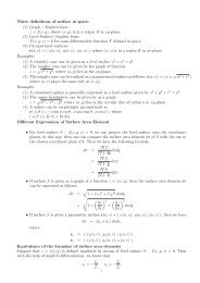
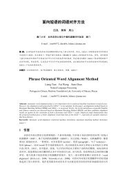
Input voltage (V)108642(a)00 1 2 3 4 5 6Time (s)Position x (µm)150100500(b)0 1 2 3 4 5 6 7 8 9Input voltage (V)Fig. 7. (a) Input voltage signal applied to the PZT #3; (b) output motions<strong>of</strong> the <strong>XYZ</strong> stage in the three axes.B. Experimental Testing <strong>and</strong> ResultsThe open-loop static properties <strong>of</strong> the XY stage are experimentallytested. With a 0.5-Hz sinusoidal voltage signalranging from 0 to 8.5 V [see Fig. 7(a)] provided by theD/A board, which is then applied to the piezo-amplifierto produce a voltage <strong>of</strong> 0–75 V to drive the PZT #3, thethree axial translations <strong>of</strong> the <strong>XYZ</strong> stage are all recordedin Fig. 7(b). As expected, with the open-loop voltage-drivenstrategy, the PZT exhibits nonlinearity mainly attributed tothe hysteresis effects. Specifically, the relationship betweenthe stage output displacement <strong>and</strong> input voltage <strong>of</strong> PZTis nonlinear as illustrated by hysteresis loops in Fig. 7(b).It is observed that the maximum translational motions inthe z-, x- <strong>and</strong> y-axes are 164.8 µm, 6.7 µm, <strong>and</strong> 7.2 µm,respectively.In view <strong>of</strong> the stroke (20 µm) <strong>of</strong> the PZT, the amplificationratio <strong>of</strong> the stage can be determined as 8.2, which is largerthan the FEA result. The reason mainly comes from thepreloading effect <strong>of</strong> the PZT mounting. Since the PZT isinserted into the mechanical amplifier <strong>and</strong> preloaded usinga screw, the initial values for the parameters l x <strong>and</strong> l y (seeFig. 4) are increased <strong>and</strong> deceased, respectively. Hence, theratio <strong>of</strong> l x /l y is greater than the nominal value. Thus, anamplification ratio larger than the expected value is achieved.Moreover, comparing to the predominant z-axis motion,the parasitic translations in the x- <strong>and</strong> y-axes accountfor 4.1% <strong>and</strong> 4.4%, respectively. The experimental resultsdemonstrate the low-level parasitic motions <strong>of</strong> the <strong>XYZ</strong>stage, which allows the employment <strong>of</strong> SISO controllerdesigns for the three axes in the future works. The crosstalkbetween the three axes mainly comes from manufacturingerrors <strong>of</strong> the stage, mounting errors <strong>of</strong> the displacementsensors with respect to sensor targets, <strong>and</strong> Abbe errorsdue to the <strong>of</strong>fset distance between the measurement point<strong>and</strong> motion axis direction <strong>of</strong> the stage. The piezoelectrichysteresis effects <strong>and</strong> cross-axis errors will be compensatedby a closed-loop controller design in the next step research.The positioning repeatability <strong>and</strong> accuracy will be calibratedas well.VII. CONCLUSIONThe design, modeling, simulation, <strong>and</strong> experimental testing<strong>of</strong> a new decoupled <strong>XYZ</strong> parallel micropositioningstage are reported in this paper. The stage owns a simplestructure <strong>and</strong> has both input <strong>and</strong> output decoupling propertiesin virtue <strong>of</strong> motor isolation <strong>and</strong> decoupled output motion.zxyA displacement amplifier with large transverse stiffness isadopted to amplify the linear motor’s stroke <strong>and</strong> to isolatethe motors. Based on the derived analytical models <strong>of</strong> thestage, dimension optimization is performed to achieve an<strong>XYZ</strong> stage with maximal natural frequency subject to theworkspace <strong>and</strong> stiffness performance constraints. With theoptimized parameters, a prototype <strong>XYZ</strong> stage is fabricated<strong>and</strong> its kinematics performances are tested. Experimentalresults show that the crosstalk between the working axes isless than 4.5%, which indicates a nice decoupling property<strong>of</strong> the developed <strong>XYZ</strong> stage. In our future works, thepiezoelectric nonlinearity <strong>of</strong> the stage will be suppressedby a suitable control system design, <strong>and</strong> the applicationin manipulating microscopic objects will be performed todemonstrate the stage ability as well.REFERENCES[1] J. Hesselbach <strong>and</strong> A. Raatz, “Pseudo-elastic flexure-hinges in robotsfor micro assembly,” in Proc. <strong>of</strong> SPIE, vol. 4194, 2000, pp. 157–167.[2] B.-J. Yi, G. Chung, H. Na, W. Kim, <strong>and</strong> I. Suh, “<strong>Design</strong> <strong>and</strong>experiment <strong>of</strong> a 3-DOF parallel micromechanism utilizing flexurehinges,” IEEE Trans. Robot. Automat., vol. 19, no. 4, pp. 604–612,2003.[3] S. Awtar <strong>and</strong> A. H. Slocum, “Constraint-based design <strong>of</strong> parallelkinematic XY flexure mechanisms,” ASME J. Mech. Des., vol. 129,no. 8, pp. 816–830, 2007.[4] J.-C. Shen, W.-Y. Jywe, H.-K. Chiang, <strong>and</strong> Y.-L. Shu, “Precisiontracking control <strong>of</strong> a piezoelectric-actuated system,” Precis. Eng.,vol. 32, no. 2, pp. 71–78, 2008.[5] R.-F. Fung, Y.-L. Hsu, <strong>and</strong> M.-S. Huang, “System identification <strong>of</strong>a dual-stage XY precision positioning table,” Precis. Eng., vol. 33,no. 1, pp. 71–80, 2009.[6] www.physikinstrumente.com/en/products/prdetail.php?sortnr=800900.[7] J. E. McInroy, “Modeling <strong>and</strong> design <strong>of</strong> flexure jointed stewartplatforms forcontrol purposes,” IEEE/ASME Trans. Mechatron., vol. 7,no. 1, pp. 95–99, 2002.[8] X.-J. Liu, J. I. Jeong, <strong>and</strong> J. Kim, “A three translational DoFs parallelcube-manipulator,” Robotica, vol. 21, no. 6, pp. 645–653, 2003.[9] T.-F. Niaritsiry, N. Fazenda, <strong>and</strong> R. Clavel, “Study <strong>of</strong> the sources <strong>of</strong>inaccuracy <strong>of</strong> a 3 DOF flexure hinge-based parallel manipulator,” inProc. <strong>of</strong> IEEE Int. Conf. on Robotics <strong>and</strong> Automation, 2004, pp. 4091–4096.[10] H.-H. Pham <strong>and</strong> I.-M. Chen, “Stiffness modeling <strong>of</strong> flexure parallelmechanism,” Precis. Eng., vol. 29, no. 4, pp. 467–478, 2005.[11] K. A. Jensen, C. P. Lusk, <strong>and</strong> L. L. Howell, “An <strong>XYZ</strong> micromanipulatorwith three translational degrees <strong>of</strong> freedom,” Robotica, vol. 24,no. 3, pp. 305–314, 2006.[12] H. Wang <strong>and</strong> X. Zhang, “Input conpuling analysis <strong>and</strong> optimal design<strong>of</strong> a 3-DOF compliant micro-positioning stage,” Mech. Mach. Theory,vol. 43, no. 4, pp. 400–410, 2008.[13] Y. Li <strong>and</strong> Q. Xu, “<strong>Design</strong> <strong>and</strong> analysis <strong>of</strong> a totally decoupled flexurebasedXY parallel micromanipulator,” IEEE Trans. Robot., vol. 25,no. 3, pp. 645–657, 2009.[14] X. Tang <strong>and</strong> I.-M. Chen, “A large-displacement 3-DOF flexure parallelmechanism with decoupled kinematics structure,” in Proc. <strong>of</strong> IEEE Int.Conf. on Intelligent Robots <strong>and</strong> Systems, 2006, pp. 1668–1673.[15] Y. Amirata, F. Artiguea, <strong>and</strong> J. Pontnau, “Six degrees <strong>of</strong> freedomparallel robots with C5 links,” Robotica, vol. 10, no. 1, pp. 35–44,1992.[16] S. T. Smith, <strong>Flexure</strong>s: Elements <strong>of</strong> Elastic Mechanisms. New York:Gordon <strong>and</strong> Breach, 2000.[17] M. Clerc <strong>and</strong> J. Kennedy, “The particle swarm-explosion, stability,<strong>and</strong> convergence in a multidimensional complex space,” IEEE Trans.Evol. Comput., vol. 6, no. 1, pp. 58–73, 2002.[18] Q. Xu <strong>and</strong> Y. Li, “Error analysis <strong>and</strong> optimal design <strong>of</strong> a class <strong>of</strong>translational parallel kinematic machine using particle swarm optimization,”Robotica, vol. 27, no. 1, pp. 67–78, 2009.[19] B. Birge, “PSOt – a particle swarm optimization toolbox for usewith Matlab,” in Proc. <strong>of</strong> IEEE Swarm Intelligence Symposium,Indianapolis, Indiana, USA, 2003, pp. 182–186.3687