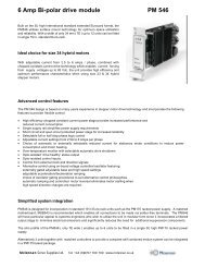
PM546 - Stepper Drive - Mclennan Servo Supplies Ltd.
PM546 - Stepper Drive - Mclennan Servo Supplies Ltd.
PM546 - Stepper Drive - Mclennan Servo Supplies Ltd.

You also want an ePaper? Increase the reach of your titles
YUMPU automatically turns print PDFs into web optimized ePapers that Google loves.
<strong>PM546</strong> ManualContentsCONTENTS________________________________________________________________________________01.0 OVERVIEW___________________________________________________________________________21.1 FEATURES ___________________________________________________________________________22.0 SPECIFICATIONS _____________________________________________________________________33.0 DRIVE CONTROL FEATURES __________________________________________________________43.1 USE WITH EXTERNAL STEP AND DIRECTION SIGNALS ___________________________________________43.2 USE WITH ON BOARD OSCILLATOR _________________________________________________________43.3 USE OF OTHER CONTROL INPUTS, STATUS OUTPUT, STEP AND DIRECTION OUTPUTS ____________________54.0 INSTALLATION_______________________________________________________________________64.1 PHYSICAL INSTALLATION________________________________________________________________64.2 POWER SUPPLY CONNECTIONS ____________________________________________________________64.3 CONNECTIONS USING EXTERNAL STEP AND DIRECTION SIGNALS __________________________________74.4 CONNECTIONS USING ON BOARD OSCILLATOR ________________________________________________74.5 CONNECTIONS FOR OTHER CONTROL INPUTS AND STATUS OUTPUT ________________________________84.6 MOTOR CONNECTIONS USING TWISTED WIRES.________________________________________________95.0 CONFIGURATION. ___________________________________________________________________115.1 CONTROL SETTINGS ___________________________________________________________________115.2 CURRENT SETTINGS ___________________________________________________________________125.3 OSCILLATOR SET-UP __________________________________________________________________126.0 <strong>PM546</strong> REAR CONNECTOR PIN ASSIGNMENTS ________________________________________137.0 MSB543 MOTHERBOARD _____________________________________________________________148.0 LIMITATIONS OF USE________________________________________________________________15SAFETY NOTICE !Motor drive systems are inherently hazardous. Even a small motor, if coupled to aleadscrew, gearbox, or any other form of mechanism which provides amechanical advantage, can generate considerable force and could cause seriousinjury. Incorrect operation can also cause damage to the motor or associatedmachinery.CautionSTATIC SENSITIVE DEVICESThis unit has static sensitive devices. Observe handling precautions:Hold card by edges only. Do not touch connector pins. Ship only in antistaticpackaging.Printed 25 July 2005page 1
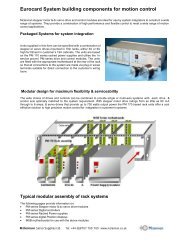
<strong>PM546</strong> Manual1.0 OverviewThis unit is designed to be an economic and compact bi-polar drive for stepper motors. Itconforms to the international 3U extended eurocard standard. They are ideally suited for usewith 2/4 phase hybrid stepper motors with current ratings from 2.5 to 6.0 amps per phase such asthe NEMA size 23 & 34 HS series. The ability to operate with rail voltages up to 80V DCprovide enhanced high speed performance with a choice of full step or half step phase controlwhen improved low speed and mid range stability is achieved.1.1 Features• Chopped constant current power stages provide increased performance and reduced currentconsumption.• Full or half step phase control logic.• Suitable for 4, 6 & 8 lead size 23 to 34 hybrid and permanent magnet stepper motors.• Current settings from 2.5A to 6A per phase, set by on board DIP switches.• Automatic or externally controlled reduced current setting for operating motor in stationarycondition.• Opto-isolated control inputs.• On board selection of full step/half step control.• On board motor direction reversal.• Heatsink overtemperature sensor with selectable automatic drive shutdown.• On board ramping oscillator for manual control.• Front panel status LED indicator• Opto-isolated drive healthy status output.• Standard 100 x 220mm extended EUROCARD format.• <strong>PM546</strong> is fitted with a front panel for fitting in a 3U rack.page 2
<strong>PM546</strong> Manual2.0 SpecificationsSupply:Motor output:Current/phase:Reduced current:20V – 80V DC.2 phase bi-polar, chopped constant current.2.5 to 6.0 amps/phase; set by on board switches.Approximately 20 - 25% of set current.Reduced current control: Automatic at standstill (switch selectable) or by external control input.Step logic:Step control:Direction control:Enable control:Oscillator control:Full or half step; selected by on board switch.Opto-isolated input. 20KHz maximum, 6µS minimum pulse width.Opto-isolated input. Sense of direction reversed by on board switch.Opto-isolated input. Enable or disable selected by on board switch.Opto-isolated inputs.OSC-RUN - Starts oscillator running.OSC-HIGH - Selects BASE speed or HIGH speed.Oscillator speed control: BASE set by on board pot (2-600Hz).HIGH set by external pot (600-15KHz).RAMP rate set by on board pot.Thermal protection:80ºC thermal sensor. Automatic latched drive disable selected by onboard switch. Reset on power on.Status LED: GREEN - <strong>Drive</strong> OK and enabled.YELLOW - <strong>Drive</strong> not enabled.RED - Fault (overtemperature).Status output:Opto-isolated inputs:Step./ direction outputsPackaging:Opto-isolated output. 10mA maximum. On when OK.3-5V or 10-30V inputs. Fully isolated.Open collector (30V 5mA maximum).3U high extended eurocard for 19” rack mounting. 7E wide.228 x 100 x 34 mm without front panel245 x 128 x 35 mm with front panelWarning!Do not connect or disconnect the motor whilst the unit is powered.page 3
<strong>PM546</strong> Manual3.0 <strong>Drive</strong> Control FeaturesThis unit has opto-isolated control input that may be controlled by either 5V (nominal)signals or by 24V (nominal) signals, depending on which input terminal is used.To energise the input with a 5V signal, apply the signal between the 5V (5) and 0V (0)terminals.To energise the input with a 24V signal, apply the signal between the 24V (24) and 0V (0)terminals.5V input24V input524560Ω2K7Ω0V return0The <strong>PM546</strong> is designed to be used either by external clock and direction signals or by the onboard oscillator.For information concerning step size selection, direction reversal, automatic powerreduction, thermal shutdown and enable polarity see the Configuration section of this manual.There is a front panel mounted status LED. It indicates the following states:GREEN - <strong>Drive</strong> OK and enabled.YELLOW - <strong>Drive</strong> not enabled.RED - Fault (overtemperature).3.1 Use with external step and direction signalsWhere the motor is to be controlled by an external controller, the step (clock) pulse anddirection control outputs of the controller should be connected to the inputs of the <strong>PM546</strong>.Details of how to connect them are given in the Installation section of this manual.The motor will move one step each time the STEP input is energised. The direction ofmovement is set by the DIRECTION input. If the sense of direction is wrong for yourapplication, then it may be reversed by the DIRECTION REVERSE switch.3.2 Use with on board oscillatorThe on board oscillator may be used for manual switch control or PLC type control outputs.There are three control inputs associated with this; OSC-RUN, OSC-HIGH and DIRECTION.There are also the external SPEED pot and the on board MAX, RAMP and BASE pots.page 4
<strong>PM546</strong> ManualWhen the OSC-RUN input is energised, with the OSC-HIGH input not energised, the motorwill start to move at the speed set by the BASE speed pot. The direction of movement is set bythe DIRECTION input. If the sense of direction is wrong for your application, then it may bereversed by the DIRECTION REVERSE switch.If the OSC-HIGH input is energised, whilst the OSC-RUN is also energised, the speed willaccelerate up to the speed set by the external SPEED pot. The acceleration is at the rate set bythe RAMP pot. If the OSC-HIGH input is de-energised, then the speed will decelerate backdown to the BASE speed at the RAMP rate.If the OSC-HIGH input is permanently energised, then when the OSC-RUN input isenergised, the speed will start at the BASE speed and ramp up to the SPEED pot setting. Whenthe OSC-RUN is de-energised the speed will ramp back down to the BASE speed and then stop.If the DIRECTION input is changed whilst the motor is moving at the high speed, then thespeed will ramp down to the BASE speed before the motor direction is reversed and the speedwill ramp back up to the high speed.The high speed is set by the external SPEED pot. This pot is scaled by the MAX on boardpot. The range of the SPEED pot is therefore between the BASE speed and the full scale speedset by the MAX pot.If the SPEED pot is varied whilst the motor is moving at the high speed, then the motorspeed will ramp to the new speed at the rate set by the RAMP pot.The STEP input may be used to single step the motor, but the input should be filtered toavoid stepping on switch contact bounce.3.3 Use of other control inputs, status output, step and direction outputsThe ENABLE input is used to enable or disable the drive. The polarity of this input is set byswitch 5 of the DIP switch (see Configuration section of this manual). When the drive isdisabled, no power is applied to the motor outputs.When the POWER REDUCTION (PWR-RDN) input is energised, the output current isreduced to between 20 - 25% of the level set by the DIP switches. This control is independent ofthe automatic power reduction switch (PR).The HEALTHY output is an opto-isolated status output. This output is on when the drive isOK, but is off when the heatsink is overtemperature or when the drive has shutdown (thermalshutdown).The Step and Direction outputs are open collector outputs to 0V. These may be used to showposition on an external counter, when using the internal oscillator.page 5
<strong>PM546</strong> Manual4.0 Installation4.1 Physical installationThe drive is constructed on a single EXTENDED EUROCARD standard printed circuitboard. The dimensions of the PCB are 100mm x 220mm. It is designed for mounting in a 3Uhigh 19” rack and is fitted with a front panel that is 7HP (approx. 1.4”) wide.Connections are made via a 64 pin DIN41612 type C connector. A mating half connectormay be fitted in the 19” rack or preferably use a <strong>Mclennan</strong> PCB motherboard. The MSB543motherboard has been designed for easy installation of the <strong>PM546</strong> and other stepper motortranslator drives. It has the DIN41612 socket on one side and plug-in screw terminals on theother for external connections.Ensure that there is plenty of ventilation for this unit. It should be mounted with theheatsink fins vertical, and enough free space around it to allow unimpeded air movement.4.2 Power supply connectionsThe unit requires a single unregulated DC supply of between 20V and 80V.CAUTION: THIS UNIT MUST NOT BE REVERSE POLARISED!+20V to +80V0V+VMM0V<strong>PM546</strong> pin 1a&c,2a&cMSB543 - +VMM<strong>PM546</strong> pin 30-32a&cMSB543 - 0VMMThe following <strong>Mclennan</strong> power supply units are available for this unit.PSU Nominal Voltage CurrentMSE171, PM171 30V 3AMSE172, PM172 24V 6AMSE173, PM173 24V 12AEM174 50V 8AEM175 70V 6Apage 6
<strong>PM546</strong> Manual4.3 Connections using external step and direction signalsThe step (clock) pulse signal should be connected so that current passes through the optoisolatedSTEP input, when a motor step is required.The direction signal should be connected so that current passes through the opto-isolatedDIRECTION input, to select the required direction of motor movement.For example, if using open-collector step and direction outputs of a <strong>Mclennan</strong> PM600,PM301, PM341 or PM381 stepper motor controller, the opto-isolators may be supplied by thecontroller’s 5V output and the outputs connected to the opto-isolators return.PM3x1 pin 5aMSB301 - T1.15+5V (opto-isolator supply). Alternativelyapply 10-30V to 24V terminalsSTEP 5STEP 24560Ω2K7ΩPM3x1 pin 24aMSB301 - T2.2ClockSTEP 0DIRECTION 5560ΩDIRECTION 242K7ΩPM3x1 pin 23aMSB301 - T2.1DirectionDIRECTION 0Important: If the on board oscillator is not used, the RAMP and BASE potsshould be set fully clockwise. The SPEED pot 2 (wiper) input should be externallyconnected to 0V.SPEED 20V4.4 Connections using on board oscillatorA 10KΩ potentiometer should be connected externally to set the high speed.SPEED 310KΩ SPEED 2SPEED 1page 7
<strong>PM546</strong> ManualThe on board oscillator may be controlled by manual control switches. This followingexample uses three pushbuttons; one to move forward, one to move backward, and one to selectthe high speed. If the base speed movement is not required, then the high speed switch may bereplaced by a link.24VForwardOSC-RUN 24OSC-RUN 0FastOSC-HIGH 24OSC-HIGH 0ReverseDIRECTION 24DIRECTION 00V4.5 Connections for other control inputs and status outputThe ENABLE and PWR_RDN inputs may be connected in the same manner as the otherinputs shown above.The HEALTHY output may be used to illuminate an external LED to show that the drive isOK24V2K2ΩHEALTHY C0VHEALTHY Epage 8
<strong>PM546</strong> Manual4.6 Motor connections using twisted wires.To produce the minimum amount of radiated noise, the motor leads should be of a twistedconstruction as shown below.The cable should be screened, with the screen connected to earth at the drive end and to themotor body at the motor end. In some hazardous environments, it is not permissible to earth bothends, because of the risk of high 50Hz circulating currents if the earth loop is cut by strongmagnetic fields (in close proximity to very powerful electrical machinery). In this case the earthconnection may be made with a 1.0µF capacitor rated at 250VAC.The motor body must be earthed.Motors with eight leads, coils in parallel.1 1’ 3’ 3Phase A+Phase A-13Phase B+Phase B-242 2’ 4’ 4Motors with eight leads, coils in series.1 1’ 3’ 3Phase A+Phase A-13Phase B+Phase B-242 2’ 4’ 4page 9
<strong>PM546</strong> ManualMotors with six leads, coils in series.1 1’2’ 3’4’ 3Phase A+Phase A-13Phase B+Phase B-242 4Motors with six leads, one coil only.1 1’2’ 3’4’ 3Phase A+Phase A-13Phase B+Phase B-242 4Motor lead colours for 23HS and 34HS series motorsPhase 1 Phase 2 Phase 3 Phase 41 1’ 2 2’ 3 3’ 4 4’Red Black Red /WhiteWhite Green Orange Green /WhiteWhite /BlackAn MSB543 motherboard is available for easy screwterminal connections and rack mounting of this unit.page 10
<strong>PM546</strong> Manual5.0 Configuration.The drive is configured by a single 8 way DIP switch, near the front of the board. There arealso front panel adjust pots for setting up the oscillator.5.1 Control settingsThere are five switches for setting up the control of the drive.SS Step Size Off - Half step (400 steps per revolution with HS type motor)On - Full step (200 steps per revolution with HS type motor)DR Direction Reverse Off - Direction normalOn - Direction reversed. Used if motor turns the wrong way.PR Power Reduction Off - Automatic power reduction at standstill. At standstill, theoutput current is reduced to 20-25% of set level.On - No auto power reduction; current is reduced only byexternal PWR-RDN control input.TS Thermal Shutdown Off - Automatic thermal shutdown. The drive is latched in adisabled state when the heatsink temperature is too high.On - No auto thermal shutdown. Thermal sensor is monitored byHEALTHY output.EP Enable Polarity Off - <strong>Drive</strong> is disabled on application of external ENABLE input(drive is enabled when ENABLE input is disconnected).On - <strong>Drive</strong> is enabled on application of external ENABLE input.12345OffSSDRPRTSEPOnHalf stepDirection normalAutomatic power reductionAutomatic thermal shutdownEnable polarity - disableFull stepDirection reversedNo automatic power reductionThermal warning onlyEnable polarity - enableThe above example shown the drive set for half step, with the direction reversed, automaticpower reduction and automatic thermal shutdown (recomended), and requiring an externalenable signal.page 11
<strong>PM546</strong> Manual5.2 Current settingsThe motor phase current may be set to the required value using on board switches as shownbelow. Since the motor winding inductance may affect the actual current applied by the drive,the actual phase current applied to the motor should be checked during commissioning when themotor is in a stationary condition.678Off On 2.5A 3.1A 4.0A 4.5A 4.8A 5.2A 5.8A 6.2AThis example shows a selected current of 4.0 amps per phase.Important: When using greater than 4.5A, use either automatic power reduction or forcedair cooling.If necessary, adjustment of the set value may be obtained by using a 10KΩ potentiometer ora resistor connected between the CURRENT ADJUST input (IA) and 0V. This will allow anadjustment range of between 25% and 80% of the current value set on the switches.CURRENT ADJUST10KΩ0V5.3 Oscillator set-upThere are three pots, which are accessible through the front panel, for setting up theoscillator.MAXRAMPBASEThis sets the scaling of the external speed control pot. Turning this clockwise willincrease the full scale speed and anti-clockwise will reduce it.This sets the ramp rate when changing speed. Turning this clockwise will increasethe rate of acceleration and deceleration and anti-clockwise will reduce it.This sets the BASE oscillator speed. This is the speed when the OSC-RUN input isactive, but not the OSC-HIGH input. It also sets the speed that the motor may bestopped, started or the direction changed. Turning this clockwise will increase thebase speed and anti-clockwise will reduce it. This should ideally be set below thepull-in rate of the motor drive combination, but above the primary resonancefrequency range.If the oscillator is not used, the RAMP and BASE pots should be set fully clockwise.page 12
<strong>PM546</strong> Manual6.0 <strong>PM546</strong> Rear Connector Pin AssignmentsCONNECTOR: DIN 41612, 64 way a & c rows. PIN VIEW.STEP input +5VDIRECTION input +5VENABLE input +5VPWR-RDN input +5VOSC-RUN input +5VOSC-HIGH input +5VSPEED pot 3SPEED pot 1HEALTHY output - collector13c15c17c19c21c23c25c26c27c1a&c2a&c34a&c5a&c6a&c7a&c8a&c9a&c10a&c11a&c1213a STEP input +24V14a&c15a16a&c17a18a&c19a20a&c21a22a&c23a24a&c25a26a27a28a&c2930a&c⎫⎬ +VMM Motor Supply⎭⎫⎬ MOTOR phase A+⎭⎫⎬ MOTOR phase A-⎭⎫⎬ MOTOR phase B+⎭⎫⎬ MOTOR phase B-⎭STEP input 0VDIRECTION input +24VDIRECTION input 0VENABLE input +24VENABLE input 0VPWR-RDN input +24VPWR-RDN input 0VOSC-RUN input +24VOSC-RUN input 0VOSC-HIGH input +24VOSC-HIGH input 0VSPEED pot 2 (wiper)Opto-isolator supply outputHEALTHY output - emitterCURRENT ADJUST input⎫⎪31a&c ⎬0VMM Supply⎪32a&c ⎭page 13
<strong>PM546</strong> Manual8.0 Limitations of UseThis unit is designed to drive a bi-polar stepper motor.Good engineering practices should be employed when using this product.The operating temperature should be between 0ºC and 30ºC.Users should take suitable precautions in the application of this product, to ensure that theoverall system complies with EN50081-1 and EN50082-1 (EMC directive).These products should not be put into service until the machinery in which they are incorporatedhas been declared in conformity with the provisions of The Supply of Machinery (Safety)Regulations 1992 and The Supply of Machinery (Safety) (Amendment) Regulations 1994(Machinery directive).Motor control systems are inherently hazardous. Even a small motor, if coupled to a leadscrew,gearbox, or any other form of mechanism which provides a mechanical advantage, can generateconsiderable force and could cause serious injury. Incorrect operation can also cause damage tothe motor or associated machinery.page 15