Installation Manual - Liberty Pumps
Installation Manual - Liberty Pumps
Installation Manual - Liberty Pumps

Create successful ePaper yourself
Turn your PDF publications into a flip-book with our unique Google optimized e-Paper software.
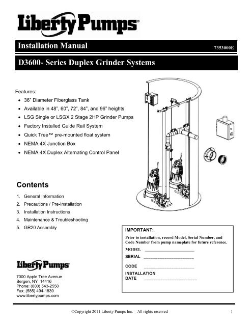
1 General InformationGRINDER PUMP SPECIFICATIONSMODELHPVOLTAGEPHASEFULLLOADAMPSLOCKEDROTORAMPSTHERMALOVERLOADTEMPSTATORWINDINGCLASSSHUT-OFFHEADCORDLENGTHFTDISCHARGELSG202A 2 208/230 1 15 53 135˚C 275°F B 108’ 25 1-1/4”LSG202M 2 208/230 1 15 53 135˚C 275°F B 108’ 25 1-1/4”LSG202M-C* 2 208/230 1 15 53 135˚C 275°F B 108’ 35 1-1/4”LSG203M 2 208/230 3 10.6 61 N/A B 108’ 25 1-1/4”LSG204M 2 440/460 3 5.3 31 N/A B 108’ 25 1-1/4”LSG205M 2 575 3 4.9 31 N/A B 108’ 25 1-1/4”LSGX202A 2 208-230 1 15 53 135˚C 275°F B 185’ 25 1-1/4”LSGX202M 2 208-230 1 15 53 135˚C 275°F B 185’ 25 1-1/4”LSGX202M-C* 2 208-230 1 15 53 135˚C 275°F B 185’ 35 1-1/4”LSGX203M 2 208/230 3 10.6 61 N/A B 185’ 25 1-1/4”LSGX204M 2 440/460 3 5.3 31 N/A B 185’ 25 1-1/4”LSGX205M 2 575 3 4.9 31 N/A B 185’ 25 1-1/4”*Note: LSG202M-C & LSGX202M-C are for external capacitor applications and require the use of control panels fitted with properlymatched capacitors and start relays.Maximum fluid temperature: 140F (60C)The grinder pump and the control panel are supplied with their own separate <strong>Installation</strong>/Operation/Maintenancemanuals. Ensure that you have received these manuals, and that you read and understand them prior to installing this unit. Yourfamiliarity with the grinder pump manual and the control panel manual is critical. This installation manual gives a brief overview of thesystem, and deals mainly with inspection and installation of the basin, but it does not cover the specifics of the pump operation or thecontrol panel operation. If you have any questions, call customer service at (800) 543-2550.2 Precautions / Pre-<strong>Installation</strong>Risk of electric shock. Always disconnect the pump from the power source before handling or making adjustments.These pumps are not to be installed in locations classified as hazardous in accordance with the National Electric Code, ANSI/NFPA70.The electrical connections and wiring for a pump installation should only be made by qualified personnel.This pump is supplied with a grounding conductor or a grounding-type attachment plug. To reduce the risk of electric shock, becertain that the grounding conductor is connected only to a properly grounded control panel or, if equipped with a grounding-typeplug, that it is connected to a properly grounded, grounding-type receptacle.Do not bypass grounding wires or remove ground prong from attachment plugs.Do not remove cord and strain relief, and do not connect conduit to pump.Do not use an extension cord.This system requires separate, properly fused and grounded branch circuit. Make sure the power source is properly sized for thevoltage and amperage requirements of the system, as noted on the nameplate.The installation must be in accordance with the National Electric Code and all applicable local codes and ordinances.Sump and sewage pumps often handle materials which could cause illness or disease. Wear adequate protectiveclothing when working on a used pump or piping.Never enter a pump basin after it has been used. Sewage and effluent can emit several gases which are poisonous.©Copyright 2011 <strong>Liberty</strong> <strong>Pumps</strong> Inc. All rights reserved 2
Pre-installation checklist:1. Inspect the unit upon arrival to ensure that there isno shipping damage. Pay careful attention to thecondition of the fiberglass basin, control floats,pump guide rail brackets, and control panel. Notifythe carrier immediately if there is any damage.2. Read all instructions and familiarize yourself withthe unit’s operation prior to proceeding with theinstallation.3. A qualified licensed electrician should install andtest all electrical circuits.4. Check to ensure that your power source is adequateto handle the pump amperage as noted above and onthe pump nameplate. Ensure that the electrical supplycircuit is equipped with fuses or breakers of the propercapacity.5. A separate 115V branch circuit should be installed forthe control circuit. We do not recommend splittingthe incoming pump power circuit to power the controlcircuit.6. All electrical connections should be tested to ensurethat a proper ground has been established3 <strong>Installation</strong> Instructions1. Excavation: Excavate the hole for the basin as small as possible, with a minimum base diameter of 50”. Neverplace the basin in direct contact with rocks or other sharp objects. Place enough fine, 1/8" to 3/4" pea gravel or1/8" to 1/2" washed, crushed stone at the bottom of the excavation to create a minimum of 12 inches stone orgravel after compaction. Do not use sand or native soil as backfill*. Properly compact underneath the basin toprovide a solid, level base that can support the weight of the filled basin. If a concrete pad will be used under thebasin, the compacted stone sub-base can be reduced to 6 inches.2. Connections & Backfill: Pour enough concrete over and around the anti-floatation flange to anchor the basinand prevent upward movement. Connect 2” schedule 80 PVC pipe to the pump discharge. Do not reduce thesize of the discharge piping, and do not increase the discharge piping to larger than 3”. The remainder of thedischarge line should be as short as possible with a minimum number of turns. Connect the inlet line to the 4”inlet hub with a rubber donut (<strong>Liberty</strong> #6112000). Connect the electrical coupling to 2” electrical conduit and runthe power and float cords through the conduit to the control panel. The remaining backfill should be only fine, 1/8"to 3/4" pea gravel or 1/8" to 1/2" washed, crushed stone. Do not use sand or native soil as backfill*. Do Not exertheavy pressure or run heavy equipment over the backfill material, as it may cause tank collapse.*Other backfill options may be available – consult the factory for special instructions relative to your situation.3. Venting: The fiberglass basin providedwith the system must be completely sealedand properly vented in order to meet healthand plumbing code requirements. Thesystem is designed to be vented throughthe inlet to an existing building vent stack.In order to accomplish this, there must beno traps between the system inlet and thenearest building vent stack connection.See Figure A for an example. If this is notpossible or desirable in your application, avent flange or grommet can be installed ina hole cut into the solid fiberglass cover.D3600SeriesSystemFigure A – Inlet Venting©Copyright 2011 <strong>Liberty</strong> <strong>Pumps</strong> Inc. All rights reserved 3
4. Control Panel:Risk of Electric shock: This pump is supplied with a grounding conductor. To reduce the risk ofelectric shock, be certain that it is connected only to a properly grounded earth wire. All electrical circuitry should beinstalled in accordance with the National Electric Code (NEC) and all applicable local codes or ordinances.The control panel that is an integral part of this complete unit is supplied with its own separate<strong>Installation</strong>/Operation/Maintenance manual. Ensure that you have received this manual, and that you read andunderstand it prior to installing this unit. Your familiarity with the control panel manual is critical.A separate 115V branch circuit should be installed for the control circuit. We do not recommend splitting theincoming pump power circuit to power the control circuit. Connect the grinder pump leads and the float switch leadsto the control panel in accordance with the instructions included with those units.5. Float Switches: The float switches are pre-mounted on a quick tree. For quick tree removal, loosen the cord nutand pull the tree straight out of the tank. The pump cycle is pre-set at the factory at 12” for D3648 (approximately53 gallons) and 18” for D3672 (approximately 79 gallons). The pump cycle can be adjusted by loosening the cordclamp and moving the “on” float up or down. We do not recommend adjustments of more than 3” in eitherdirection – please call the factory if you need to adjust the pump cycle beyond this recommended level.6. Testing and Startup: Follow the testing and startup procedures found in the grinder pump and control panelmanual.4 Maintenance and TroubleshootingThe grinder pump and control panel are supplied with their own separate<strong>Installation</strong>/Operation/Maintenance manuals. Ensure that you have received these manuals, and that you read andunderstand them prior to installing this unit. Your familiarity with the grinder pump manual and the control panel manual iscritical. Please follow the Maintenance and Troubleshooting procedures provided in those manuals.ModelD3648D3660D3672D3684D3696OffLevel13”(33 cm)13”(33 cm)13”(33 cm)13”(33 cm)13”(33 cm)OnLevel25”(64 cm)28”(71 cm)31”(79 cm)34”(86 cm)37”(94 cm)Alarmlevel31”(79 cm)34”(86 cm)37”(94 cm)40”(102 cm)43”(109 cm)Volume/cycle62 gal.(235 liters)75 gal.(284 liters)88 gal.(333 liters)101 gal.(382 liters)115 gal.(435 liters)©Copyright 2011 <strong>Liberty</strong> <strong>Pumps</strong> Inc. All rights reserved 4
5 GR20 Quick Disconnect AssemblyGR20 AssemblyThe GR20 quick disconnect assembly provided with your grinder package system is designed to allow easy installationand removal of the pump. When installed correctly it will seal and provide a means to lift the pump without disconnectingany of the discharge piping. Please ensure that installation is done as per the diagrams below.ENSURE THATGROMMET ISPROPERLYINSTALLEDINSTALL 3/8X16 HEX BOLTSHERE. EVENLY TIGHTENBOTH SIDES SO THATGASKET IS PROPERLYCOMPRESSED.ENSURE THAT RUBBERGROMMET IS PROPERLYINSTALLED HERE.1-1/4"GUIDE RAIL PIPE1-1/4"DISCHARGEPIPEDISCONNECTED POSITION PIPE GUIDE ASSEMBLY OPERATING POSITION©Copyright 2011 <strong>Liberty</strong> <strong>Pumps</strong> Inc. All rights reserved 5
3 Year Limited Warranty<strong>Liberty</strong> <strong>Pumps</strong>, Inc. warrants that pumps of its manufacture are free from all factory defects in material and workmanshipfor a period of 3 years from the date of purchase. The date of purchase shall be determined by a dated sales receiptnoting the model and serial number of the pump. The dated sales receipt must accompany the returned pump if the dateof return is more than 3 years from the "CODE" (date of manufacture) number noted on the pump nameplate.The manufacturer's obligation under this Warranty shall be limited to the repair or replacement of any parts found by themanufacturer to be defective, provided the part or assembly is returned freight prepaid to the manufacturer or itsauthorized service center, and provided that none of the following warranty-voiding characteristics are evident:The manufacturer shall not be liable under this Warranty if the product has not been properly installed; if it has beendisassembled, modified, abused or tampered with; if the electrical cord has been cut, damaged or spliced; if the pumpdischarge has been reduced in size; if the pump has been used in water containing sand, lime, cement, gravel or otherabrasives; if the pump has been used in water above the advertised temperature rating; if the product has been used topump chemicals or hydrocarbons; if a non-submersible motor has been subjected to excessive moisture; or if the labelbearing the serial, model and code number has been removed.<strong>Liberty</strong> <strong>Pumps</strong>, Inc. shall not be liable for any loss, damage or expenses resulting from installation or use of its products,or for consequential damages, including costs of removal, reinstallation or transportation.There is no other express warranty. All implied warranties, including those of merchantability and fitness for aparticular purpose, are limited to three years from the date of purchase.This Warranty contains the exclusive remedy of the purchaser, and, where permitted, liability for consequentialor incidental damages under any and all warranties are excluded.7000 Apple Tree AvenueBergen, NY 14416Phone: (800) 543-2550Fax: (585) 494-1839www.libertypumps.com©Copyright 2011 <strong>Liberty</strong> <strong>Pumps</strong> Inc. All rights reserved 6