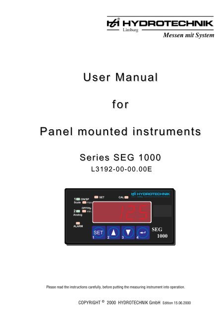
neuBAW SEG 1000 engl. - Hydrotechnik
neuBAW SEG 1000 engl. - Hydrotechnik
neuBAW SEG 1000 engl. - Hydrotechnik

Create successful ePaper yourself
Turn your PDF publications into a flip-book with our unique Google optimized e-Paper software.
ForewordThe following user manual describes all analogue and digital panel mounted instruments of series <strong>SEG</strong> <strong>1000</strong>, manufactured byHYDROTECHNIK.In today’s metrology, sensors with standardised output signals are used for a trouble-free transfer of measuring signals. To follow this aspect,our panel mounted instruments were designed for the connection to sensor-input signals of 0 to 20 mA or 4 to 20 mA, which are evaluatedwith an analogue measuring instrument of series <strong>SEG</strong> <strong>1000</strong>.For sensors that supply a frequency signal, an input signal range for square wave signals from the TTL-level up to the max. sensor supplyvoltage of 15 VDC is provided. The frequency signals are evaluated with a digital measuring instrument of series <strong>SEG</strong> <strong>1000</strong>.The state-of-the-art instruments of series <strong>SEG</strong> <strong>1000</strong> are very accurate and easy to use.Their compact design with the dimensions 96 x 48 mm allows the mounting into all customary housings and front elements. The instrumentsare used and programmed through the front, only, without having to remove the front frame.Here you can see the technical features of the panel mounted instrument of series<strong>SEG</strong> <strong>1000</strong>, at a glance:- standardised fitting dimensions 96 x 48 mm according to DIN 43 718- very good legibility of the LED-display, even from larger distances- acquisition of analogue sensor-signals 0 to 20 mA and 4 to 20 mA- acquisition of frequency signals (1 Hz to 10.000 Hz)- storage of extreme values (min./max.)- adjustment of limit values (min./max.) which serve for example for the external controlof contactors through potential-free relay contacts- adhesive foil to inscribe the different measuring units easily- analogue outputs 0 to 20 mA/0 to 10 Volt or 4 to 20 mA/2 to 10 V- voltage supply either 24 VDC or 230 VACYou will surely have no problems in handling the <strong>SEG</strong> <strong>1000</strong>-instrument, but you will only be able to use all possibilities of the instrument, ifyou know it well.Should you have any difficulties in understanding nevertheless, please do not hesitate to contact us, we will do our best to help you.We reserve the right to make modifications, necessary for the technical progress.We wish you much success for the application of our panel mounted instruments of series:<strong>SEG</strong> <strong>1000</strong>-2-
IndexSecurity advice page 41. Connection of the measuring instrument page 51.1 Preparation for connection page 61.2 Measuring cable MK15 page 61.3 Fitting situation page 72. First putting into operation page 82.1 Configuration of the measuring instrument page 83. Survey on the menu steps for both types of measuring instruments page 94. Adjustments of the measuring instrument with analogue input page 104.1 Selection measuring signal input for the analogue measuring instrument page 104.2 Display with decimal point page 114.3 Selection of the measuring range end value page 114.4 Selection of the beginning of the measuring range page 124.5 Manual zero point correction page 124.6 Selection of the display speed with filter possibilities page 134.7 Adjustment or scaling of the analogue output page 144.8 Analogue output voltage page 144.9 Analogue output current page 154.10 Spreading of the measuring range page 154.11 Finishing the configuration page 164.12 Examples for adjustment: analogue output page 165. Adjustments of the measuring instrument with digital input page 175.1 Selection of the decimal point page 185.2 Input of the calibration value page 195.3 Selection of the display speed with filter possibilities page 205.4 Adjustment or scaling of the analogue output page 215.5 Analogue output voltage page 215.6 Analogue output current page 225.7 Spreading of the measuring range page 225.8 Finishing the configuration page 236. Programming of the min.- and max. values for relay 1 and 2 page 247. Display of min./max. values page 268. Error messages page 279. Connection of the different sensors in 2-, 3- and 4-wire technique page 2810. HYDROTECHNIK-sensors with connection schemes page 3011. Technical data page 3312. Information on guarantee page 3413. Maintenance page 34-3-
Security advicePlease take the following into consideration, to exclude an endangering of the user:a) Switch the instrument off immediately, if you recognise damages or failures or if you detect a bad smell or smoke.b) Please avoid to open the instrument by yourself !Before opening, separate the instrument from the power supply.When mounting the instrument and the connections, please take care, that all parts are protected from direct contact(when opening the instrument the guarantee will become invalid).c) Please pay attention to the usual safety regulations for electric-, weak- and strong current plants, especially the security regulations inyour country (e.g. VDE 0100).d) Connections to other instruments should be carried out very carefully.It can happen that internal connections in instruments from other manufacturers (for example, connection GND with protective ground)cause voltage potentials, that are not allowed.Warning:When operating electrical instruments, parts of the instrument have a dangerous voltage. Therefore the disregard of thesecurity regulations may cause heavy physical injuries or damages of property.Only qualified personnel should operate these instruments.Conditions for the unobjectionable and safe operation of this instrument are the proper transport, storage, installation andmounting, as well as the careful operation and maintenance.Please clean the front of the housing with a soft cloth, moistened with a mild detergent(Please pay attention to the notes of the manufacturer).Qualified personnelare people who are familiar with the installation, mounting, putting into operation and the operation of the product and who have thecorresponding qualifications.For example:• Education, training or authorisation to switch ON/OFF, clear, ground and mark circuits and instruments/systems according to thestandards of safety engineering.• Education or training for maintenance and use of appropriate safety equipment according to the standards of safety engineering.• Training for First Aid.-4-
1. Connection of the measuring instrumentElectrical connectionThe connections of the <strong>SEG</strong> <strong>1000</strong> are on the back of the instrument.The connection is carried out through terminal screws or plug-in terminals, which always should be mounted loose and afterwards screwedorplugged-in.If the terminals are already screwed- or plugged-in, lands for soldering could be broken loose. Please use a suitable screw-driver and do notfix the screws by force.Terminal connections on the backpinBridge and resistor:state at delivery17 16 15 14 13 12 11 10 9 87 65 4 3 2 1designation/functionPin 1:mains voltageL: 230VAC L -24 VDCPin 2: N: 230 VAC L+Pin 3: switch output 2Pin 4:change over contactPin 5:Pin 6:Pin 7:Pin 8:Pin 9:Pin 10:switch output1make contactSensor supply voltage +UbSensor supply voltage -UbGND/ common mass for sensor/sensor supply(bridge 9 to 10, valid also for frequency input)Pin 11: sensor signal + (0 to 20/4 to 20 mA)Pin 12: freePin 13: sensor signal + ( 0 to 10 V)also for frequency input, signal+ (square wave 5 to 15 V)Pin 14: freePin 15: freePin 16: analogue output Signal + resistor 500 Ohm installed by manufacturerPin 17: Signal - output voltage 0 to 10 V,without resistor max. 20 mAThe indicated numbers correspond to the pin connections.When connecting, please pay attention to the right connection of the pins and their order. Please see from the label,which type of measuring instrument you have, which performance it has and with which voltage it may be operated.Only after having checked this, you should connect the corresponding voltage.Please, have your instrument connected by a well-trained expert.-5-
1.1 Preparation for connection1. Disconnect the power supply.2. Connect the different leads of the power supply with the terminal screw and plug it into the corresponding connector(mains voltage 2-poles or low-voltage 2-poles).3. Connect the different leads of the sensor cable with the terminal screw and plug it into the corresponding connector (10-poles).Please connect the other end of the measuring cable with the sensor.When using a HYDROTECHNIK sensor, you can see the pin-connection and the colour of the cables in the table, shown below.4. Option: Switch outputPlease connect the different leads of the relay output 2 change over contact with the terminal plug and plug it into the correspondingconnector (3-poles).Connect the different leads of the relay output 1 make contact with the terminal plug and plug it into the corresponding connector(2-poles).5. Option: Analogue outputPlease connect the different leads of the analogue output with the terminal plug and plug it into the corresponding connector (10-poles).1.2 Measuring cable MK15The user can order a ready-made connection cable MK15, which makes the connection of the HYDROTECHNIK-sensors easier. The free cableends are directly connected to the 10-pole plug connection. Here, you should take into consideration, if your sensor is in 2-, 3- or 4-wiretechnique and which signal output it has (0 to 20 mA, 4 to 20 mA or 0 to 10 V).According to the „terminal connections on the back“ on page 5, the fixed wiring of the connections must be carried out in this way.When manufacturing the cable by yourself, you should pay attention to the fixed wiring of the connections in any case (see following drawing).The free cable ends are directly connected to the 10-pole plug connection.to plug connection ST3sensor connectionwhitebrowngreenyellowblackcable socket 5-poleswhitebrowngreenyellowblackConnection ofthe free cableendsMeasuring cable MK15MeßkabelPart-no.: 8824-C1-02.50MK 15Bestell-Nummer 8824-C1-02.50colour pin to 10-poles plug connection of the measuring instrumentwhite 1 to pin 11 for current input; to pin 13 for voltage inputbrown 2 to pin 9green 3 to pin 8yellow free freeblack 4 to pin 9 or 10 (bridge)-6-
1.3 Fitting situationTo fit the instrument into a front panel, please see the dimensions in the illustration, shown below, and prepare the panel correspondingly.Series <strong>SEG</strong> <strong>1000</strong>: 90,5 mm43 mmSeries <strong>SEG</strong> <strong>1000</strong>: 100 mmAfter having lead the connection cables through the opening of the panel and connected them with the measuring instrument, you have topress the instrument into the opening from the front side.The two holding screws should only be fastened after the complete adjustment and calibration of the measuring instrument.To help the user to distinguish, we have attached to each instrument a foil with adhesive labels, indicating all possible measuring units.You can stick a label with the corresponding measuring unit on the front of the instrument.1 ON/SPScale max.SETCALLimburgOFF/Hy.2 min.AnalogALARMSET1 2 3 4<strong>SEG</strong><strong>1000</strong>-7-
3. Survey on the menu steps for both types of measuring instrumentsIn the following you will find a detailed description of the configuration steps for the measuring instrument with analogue input and for theinstrument with frequency input.Measuring instrument with analogue input Measuring instrument with frequency input1 ON/SPScale max.OFF/Hy.2 min.AnalogALARMSETSETCAL1 2 3 4LimburgI n 0<strong>SEG</strong><strong>1000</strong>1 ON/SPScale max.OFF/Hy.2 min.AnalogALARMSETSETCALLimburgI n 111 2 3 4<strong>SEG</strong><strong>1000</strong>1. Step: Adjustment of the measuringsignal inputselection of number 0 = 0 to 20 mAselection of number 1 = 4 to 20 mAorselection of number 3 = 0 to 10 V1. Step: Adjustment of the measuringsensitivity to TTL-level and frequencyselection of number 3 = <strong>1000</strong> Hzselection of number 7 = 100 Hzorselection of number 11 = rev. speedmeasurement2. Step: Selection of decimal pointfor the display0000 = display - - - -000.0 = display - - -.-00.00 = display - -.- -2. Step: Selection of decimal pointfor the display0000 (rev. speed measurement000.0 without decimal point)00.003. Step: Scaling of the display- Selection of the measuring end value4. Step: Scaling of the display- Selection of the beginning of themeasuring range5. Step:Selection of the display speed withdifferent filter chracteristics3. Step: Scaling of the display- Selection of the measuring end value4. Step: is skipped with key4- Selection of the beginningof the measuring range (not necessary formeasurement of frequency)5. Step:Selection of the display speed withdifferent filter chracteristics6. Step: without function, please skip“nr. 0“ is shown in the display, this6. Step: without function, please skip“nr. 0“ is shown in the display, thismessage can be skipped with key4message can be skipped with key47. Step: Scaling of the analogue output- Selection of the measuring end value8. Step: Scaling of the analogue output-Selection of the beginning of themeasuring range7. Step: Scaling of the analogue output- Selection of the measuring end value8. Step: Scaling of the analogue output-Selection of the beginning of themeasuring range9. Step:“out 1“ is shown. If you press key49. Step:“out 1“ is shown. If you press key4now, you will leave the configuration.now, you will leave the configuration.The above mentioned operating steps are described in more detail on the following pages.-9-
4. Adjustments of the measuringinstrument with analogue inputFirst of all, all operating steps for the measuring instrument withanalogue input are described.LED CAL is illuminated1 ON/SPScale max.OFF/Hy.2 min.AnalogALARMSETSETCAL1 2 3 4LimburgI n 0<strong>SEG</strong><strong>1000</strong>For calibration you should press key SET and the miniature key1on the back of the instrument (behind the terminal plug) as long as „In“is displayed together with a number.After that you can let go key SET and the miniature key.1The display looks as shown-above and the LED „CAL“ is illuminated.4.1 Selection measuring signal input for theanalogue measuring instrumentTo be able to measure with the <strong>SEG</strong> <strong>1000</strong> with analogue input, you willhave to adapt the signal input of the measuring instrument to the outputsignal of the analogue sensor, what is carried out with help of thesoftware.In the example you can see the preadjustments of the analoguemeasuring signal input.1 ON/SPScale max.SETCALLimburgOFF/Hy.2 min.AnalogALARMI n 0With one of the two cursor keys the correspondingSET1 2 3 4<strong>SEG</strong><strong>1000</strong>2 3number in the display can either be increased or decreased.If, for example, you select the number „0“, the display will show „In 0“and the measuring instrument will be adjusted to an analogue inputmeasuring signal of 0 to 20 mA.In x analogue instrument0 0 to 20 mA1 4 to 20 mA2 •3 0 to 10 V4 •5 •6 •7 •8 •10 •11 •With key4the selected number „0“ is stored in the measuringinstrument.The next operating step is displayed automatically.If an output signal of 0 to 10 V is requested for a sensor, the inputconnection on the 10-pole plug connector will need to be modified(white wire to pin 13)For this, please see the description of the connection on page 5.-10-
4.4 Selection of the beginning of the measuringrange1 ON/SPScale max.OFF/Hy.2 min.AnalogALARMLimburgSETCAL0SET1 2 3 4<strong>SEG</strong><strong>1000</strong>In the example the measuring range of the pressure sensor is 0 to 600bar.Therefore, a „0“ has to be entered with the keys and3.24.5 Manual zero point correction1 ON/SPScale max.OFF/Hy.2 min.AnalogALARMLimburgSETCAL- 3SET1 2 3 4<strong>SEG</strong><strong>1000</strong>It is also possible to use the beginning of the measuring range for thecorrection of a zero point. This can be very useful, if, for example, apressure sensor has a zero point deviation.In the measuring value display you can check, if a pressure sensor hasa zero point deviation. A condition for that is, that the pressure sensor isdepressurized.You can correct this deviation, when selecting the beginning of themeasuring range.If for example, a pressure sensor has a zero point deviation of + 3,0 bar,you have to adjust this value as a negative value (-3 bar) with key3(see display).This adjustment is stored with key and the next step isinvoked automatically.4The adjusted offset of the pressure sensor (zero point deviation) will betaken into account for all further pressure measurements and correctedby the programme.The measuring value display shows the corrected pressure measuringvalue.-12-
4.6 Selection of the display speed with filterpossibilitiesIn the display the letters „FIL“ are shown in combination with anumber (for example: FIL 0)LimburgSETCAL1 ON/SPScale max.OFF/Hy.2F i L 0min.AnalogALARMSET1 2 3 44FIL 14FIL 24FIL 34<strong>SEG</strong><strong>1000</strong>The following four possibilities can be selected:FIL 0means: The measuring value is displayed with nearly no delay,the filter is switched off.FIL 1means: The display time is delayed by 0,5 seconds, the filter is switchedon and suppresses short interfering pulses that can occur when relaysor contactors are switched.FIL 2means: The filter avoids, that the last digit in the display jumps and anadditional delaying of the display for 1 sec. is active. This filter shouldbe selected in any case, if the display is larger than 2000.FIL 3means: A combination of FIL1 and FIL2. The display delay of filter 1 andfilter 2 is added and the display changes slowly and is insensible tointerference from outside.For digital measuring instruments (measurement of frequency) with adisplay value above 2000, „FIL 2“ should be selected.After having chosen the display delay and the filter, you can store thisadjustment with key .4At the same time the display shows „nr“ with a following number.This display has no function and needs to be skipped with key .4-13-
4.7 Adjustment or scaling of the analogueoutput1 ON/SPScale max.OFF/Hy.2 min.AnalogALARMSETLimburgCAL6 0 0SET1 2 3 4Measuring range end value<strong>SEG</strong><strong>1000</strong>In the next step, the user has to adjust the analogue output.The three LEDs CAL, Analog and max. are illuminated, that means,the end and the beginning of the measuring range (limit values) needto be entered for the analogue output.Example:The limit values for a pressure sensor with a measuring range of 0 to600 bar shall be entered.First of all the end of the measuring range 600 is entered with the keys2 3and (see display 600).After that the input needs to be confirmed with key .The instrument immediately asks for the input of the beginning of themeasuring range.The LEDs CAL, Analog and min. are illuminated.In the example zero = (0) bar.4The value „0“ is adjusted with the keys and and the2 31 ON/SPScale max.OFF/Hy.2 min.AnalogALARMLimburgSETCAL0SET1 2 3 4<strong>SEG</strong><strong>1000</strong>selection should be confirmed with key .4Beginning of measuring range4.8 Analogue output voltage600(bar)450When HYDROTECHNIK delivers the measuring instrument, it isequipped with a 500 Ohm resistor that is connected between pin 16and pin 17.If for example a pressure sensor with a measuring range of 0 to 600 barand a signal output of 0 to 20 mA is connected to the measuring input,an output signal of 0 to 10 V is generated, relating to a measuring rangeof to 600 bar.For better understanding, please see diagram 1.3001500012 3 4 5 6 7 8 910 (V)Diagram 1-14-
4.9 Analogue output current600(bar)450If the 500 Ohm resistor is removed, very long wires can be bridged atthe analogue output. The analogue output provides a load independentcurrent, that means a controlled current not depending on the connectedresistor (apparent ohmic resistance).The advantage of that is, that the wire resistor and the instrument(e.g. a printer), connected with a longer wire, do not influence thecurrent signal, as long as the sum of the resistors is smaller than theallowed apparent ohmic resistance of max. 1.500 Ohm.3001500-1501 2 3 4 5 6 7 8 9 10 11 12 13 14 15 16 17 18 19 20 (mA)If, for example, a pressure sensor with a measuring range of 0 to 600bar and a signal output of 0 to 20 mA is connected to the measuringinput, a proportional output current of 0 to 20 mA referring to ameasuring range of 0 to 600 bar, is provided at the analogue output.Please see diagram 2 (full line).If, however, a current of 4 to 20 mA shall provided at the analogueoutput, the beginning of the measuring range needs to be adjusted to-150, as shown on page 14.As you can see in diagram 2, the pointed line is shifted and meets thex-axis at the 4 mA point. The zero point shifts into the negative range ofvalues (- 150 bar).Diagram 2This corresponds to exactly a quarter of the measuring range from 0 to600 bar = 150 bar.That means the output signal at 0 bar is 4 mA and the measuring rangeend value from 600 bar is 20 mA.4.10 Spreading of the measuring range500(bar)450400350If you want to restrict the measuring range from 0 to 600 bar to,e.g. 300 to 500 bar, the resulting output signal range will be proportionalto the new adjusted measuring range, that means:300 to 500 bar = 0 to 20 mATherefore, measuring values below 300 bar or 500 bar will be restrictedto 0 mA or 20 mA, see (diagram 3).In doing so, you can have the measuring range printed out in a spreadway.If an extreme spreading is carried out, steps will be printed out due tothe analogue-digital conversion.3000 1 2 3 4 5 6 7 8 9 10 11 12 13 14 15 16 17 18 19 20 (mA)Diagram 3-15-
600(bar)450Diagram 4The analogue output signal can be inverted, too.When entering the values, you only have to exchange the beginningandthe end value.Then, 600 bar corresponds to 0 mA and 0 bar corresponds to 20 mA,see diagram 4.300150001 2 3 4 5 6 7 8 9 10 11 12 13 14 15 16 17 18 19 20 (mA)4.11 Finishing the configuration1 ON/SPScale max.OFF/Hy.2 min.AnalogALARMLimburgSETCALout. 1SET1 2 3 4<strong>SEG</strong><strong>1000</strong>If the adjustments of the analogue output are finished, the display on theleft side will be shown automatically. You will always have to leave theconfiguration programme with this display „out.1“ and a stroke of key4, afterwards.The current measuring value display is shown automatically.You can repeat the programme steps for the configuration of theinstrument, described above, as often as you like. However, you shouldalways begin with the steps, described on page 14.If during the configuration, no key is pressed for two minutes, it will beinterrupted automatically. The LED „CAL“ won’t be illuminated anymore.4.12 Examples for adjustment: analogue outputAnalogue output scaled for 0 to 20 mA:If a temperature, for example of -50 °C to +150 °C, is measured at an analogue instrument and the analogue output shall provide an outputcurrent of 0 to 20 mA, proportional to the measuring range, the configuration of the analogue output needs to be adjusted to max. 150and min -50.The analogue output provides at -50 °C = 0 mA, at 0 °C = 5 mA and at 150 °C = 20 mA.Analogue output scaled for 4 to 20 mA: (only valid for a sensor that provides 4 to 20 mA, too)If, however, the analogue output shall provide an output current of 4 to 20 mA at -50 °C to + 150 °C, you only have to modify the beginning ofthe measuring range to -100 in the configuration (step 8, page 9).The analogue output provides at -50 °C = 4 mA, at 0 °C = 8 mA and at 150 °C = 20 mA.If you want to carry out further adjustments for your measuring instrument with analogue measuring input, please skip the pages 17 to 23, asthe measuring instrument with digital input (frequency input) is described on these pages.From page 24 on, you will find further adjustments for the instrument with analogue input.-16-
5. Adjustments of the measuringinstrument with digital input(frequency measurement)1 ON/SPScale max.OFF/Hy.2 min.AnalogALARMLED CAL is illuminatedSETSETCALLimburgI n 111 2 3 4<strong>SEG</strong><strong>1000</strong>All operating steps for the measuring instrument with digital measuringinput are described.For calibration you should press key SET and the miniature key on1the back of the instrument (behind the terminal plug) as long as „In“ isdisplayed together with a number.In the example „IN 11“ is displayed.After that you can let go key SET and the miniature key.1The display looks as shown-above and the LED „CAL“ is illuminated.To be able to measure frequencies with the <strong>SEG</strong> <strong>1000</strong>, you will have toadjust it to one of the following possibilities:- TTL <strong>1000</strong> Hz = 3This adjustment is suitable for the use of measuring turbines, gear flowmeters and sensors with a frequency signal(square-wave signal from 5 V to 15 V).- TTL-measurement of RPM = 11This adjustment is suitable for the use of sensors with a frequencysignal (square-wave signal from 5 V to 15 V)- Adjustment TTL 100 Hz = 7This adjustment is provided for special cases where low frequenciesshall be displayed with a high resolution (two digits behind the decimalpoint). Sensors with a frequency signal (square-wave signal from 5 V to15 V).-17-
1 ON/SPScale max.OFF/Hy.2 min.AnalogALARMSETSETCAL1 2 3 4LimburgI n 11<strong>SEG</strong><strong>1000</strong>With one of the two cursor keys the corresponding2 3number in the display can either be increased or decreased.If, for example, you select the number „11“, the display will show „In11“ and the measuring instrument will be adjusted to a frequency signalfor the acquisition of rev. speed (in doing so, the input signals perrevolution are directly calculated with the factor 60 and displayed asrevolution per minute).In x digital instrumentWith key4the selected number is stored in the measuringinstrument.The next operating step is displayed automatically.0 •1 •2 •3 TTL <strong>1000</strong> Hz4 •5 •6 •7 TTL 100 Hz8 •10 •11 TTL RPM5.1 Selection of the decimal pointWith the keys and , the position of the decimal2 3point can be moved to the left or the right side.No decimal pointselectedLimburgSETCAL1 ON/SPScale max.OFF/Hy.2 min.AnalogALARM- - - -.SET1 2 3 4<strong>SEG</strong><strong>1000</strong>According to this adjustment, the result of the measurements will bedisplayed without decimal point, with a decimal point behind threefigures or with a decimal behind two figures.Decimal point000,0selectedLimburgSETCAL1 ON/SPScale max.OFF/Hy.2 min.AnalogALARM- - -. -SET1 2 3 4<strong>SEG</strong><strong>1000</strong>With key4the selected position of the decimal point is stored.When measuring rev. speed, an input of the decimal point is notnecessary, as the resolution in the display is always 1 revolution perminute.If a decimal point is selected, it will be suppressed for the rev. speedmeasurement.Decimal point00,00selectedLimburgSETCAL1 ON/SPScale max.OFF/Hy.2 min.AnalogALARM- -. - -SET1 2 3 4<strong>SEG</strong><strong>1000</strong>The selection of the decimal point is especially important, when usingvolume flow rate sensors, as it is quite possible to exceed the displayrange, in this case.-18-
Volume flow rate sensors can have a resolution of up to two digits behind the decimal point. For the adjustment of the decimal point, youshould take the calibration value from the calibration certificate, attached to each volume flow rate sensor.In the following example you can see, when an adjustment to one digit or to two digits behind the decimal point is recommended.For measuring a volume flow rate, a measuring turbine type RE4-300 with a measuring range of 15 to 300 l/min., according to its calibrationcertificate, is used.The calibration value is 87,68. This value corresponds to a volume flow rate of 87,68 l/min. with a frequency of <strong>1000</strong> Hz.As the display of the measuring instrument can show four digits, only, the display range of 99,99 l/min. would be exceeded at a frequency of1140,5 Hz (calculated value), already.Besides that, an error „Fe 3“ would be displayed and the measurement of volume flow rate would not be possible any more.Only if the value fell below 99,99 l/min., a measurement would be possible again.To prevent faulty measurements, it would be sensible to limit the calibration value to one digit behind the decimal point and, if necessary, toround up the calibration value to 87,7, for example. In doing so, you can measure a volume flow rate of up to 300 l/min. with the measuringinstrument.5.2 Input of the calibration valueFor measuring instruments for volume flow rate, the input ofa calibration value is imperative.As an example for the input of a calibration value, the above-mentionedmeasuring turbine is used. According to its calibration certificate, themeasuring range is 15 to 300 l/min. and the calibration value is 87,68.For entering the value with one digit behind the decimal point, you haveto enter: 87,7.In HYDROTECHNIK’s sensors, for example, the calibration value canalso be seen on the label.1 ON/SPScale max.OFF/Hy.2 min.AnalogALARMLimburgSETCAL87.7SET1 2 3 4<strong>SEG</strong><strong>1000</strong>The value 87,7 in the example can be adjusted with the cursor keysand2 3The input needs to be finished with keyinvoked automatically.(see picture on the left side).4and the next step is23The two cursor keys „2“ and „3“ have a rolling function.That means, when pressing one of these keys quickly (< 1s), the valueto be adjusted will increase or decrease by one digit (1 number).When pressing these keys for a longer time, the value begins to roll andfrom 150 digits on it accelerates up to ten times the speed.To make the adjustment easier, you should let go the key from time totime and begin again with a slower speed.-19-
When measuring RPM, please pay attention to enter the number of markings, for example the reflective adhesive foil you have stuckon your object to be measured, instead of the measuring range end value. If you have stuck on only one marking, you will have toadjust the number 1 in the display. The rev. speed is acquired and displayed in RPM automatically.5.3 Selection of the display speed withfilter possibilitiesIn the display the letters „FIL“ are shown in combination with anumber (for example: FIL 0)LimburgSETCAL1 ON/SPScale max.OFF/Hy.2F i L 0min.AnalogALARMSET1 2 3 44FIL 14FIL 24FIL 3<strong>SEG</strong><strong>1000</strong>The following four possibilities can be selected:FIL 0means: The measuring value is displayed with nearly no delay, the filteris switched off.FIL 1means: The display time is delayed by 0,5 seconds, the filter is switchedon and suppresses short interfering pulses that can occur when relaysor contactors are switched.FIL 2means: The filter avoids, that the last digit in the display jumps and anadditional delaying of the display for 1 sec. is active. This filter shouldbe selected in any case, if the display is larger than 2000.FIL 3means: A combination of FIL1 and FIL2. The display delay of filter 1 andfilter 2 is added and the display changes slowly and is insensible tointerference from outside.4For digital measuring instruments (measurement of frequency) with adisplay value above 2000, „FIL 2“ should be selected.After having chosen the display delay and the filter, you can store thisadjustment with key .4At the same time the display shows „nr“ with a following number.This display has no function and needs to be skipped with key .4-20-
5.4 Adjustment or scaling of the analogueoutput1 ON/SPScale max.OFF/Hy.2 min.AnalogALARMSETLimburgCAL3 0 0SET1 2 3 4<strong>SEG</strong><strong>1000</strong>Measuring range end valueIn the next step, the user has to adjust the analogue output.The three LEDs CAL, Analog and max. are illuminated, that means, theend and the beginning of the measuring range (limit values) need to beentered for the analogue output.Example:The limit values for a measuring turbine with a measuring range of15 to 300 l/min. shall be entered.First of all the end of the measuring range 300 l/min. = 300 is enteredwith the keys and (see display 300).2 3After that the input needs to be confirmed with key .The instrument immediately asks for the input of the beginning of themeasuring range.The LEDs CAL, Analog and min. are illuminated.In the example 15 l/min. = 15 needs to be entered.4The value „15“ is adjusted with the keysand2 31 ON/SPScale max.OFF/Hy.2 min.AnalogALARMLimburgSETCAL15SET1 2 3 4<strong>SEG</strong><strong>1000</strong>and the selection should be confirmed with key .4Beginning of measuring range5.5 Analogue output voltage300(l/min)225When HYDROTECHNIK delivers the measuring instrument, it isequipped with a 500 Ohm resistor that is connected between pin 16and pin 17.If for example a turbine with a measuring range of 15 to 300 l/min.is connected to the measuring input, an output signal of 0 to 10 Vis generated, relating to a measuring range of 15 to 300 bar.For better understanding, please see diagram 5.1507515012 34 5 6 89710 (V)Diagram 5-21-
5.6 Analogue output current300(l/min)22515075If the 500 Ohm resistor is removed, very long wires can be bridged atthe analogue output. The analogue output provides a load independentcurrent, that means a controlled current not depending on the connectedresistor (apparent ohmic resistance).The advantage of that is, that the wire resistor and the instrument(e.g. a printer), connected with a longer wire, do not influence thecurrent signal, as long as the sum of the resistors is smaller than theallowed apparent ohmic resistance of max. 500 Ohm.If, for example, a measuring turbine with a measuring range of 15 to300 l/min. is connected to the measuring input, a proportional outputcurrent of 0 to 20 mA referring to a measuring range of 15 to 300 l/min.,is provided. Please see diagram 6 (full line).If, however, a current of 4 to 20 mA shall provided at the analogueoutput, the beginning of the measuring range needs to be adjusted to-75,0 in the display, as shown on page 14.15-751 2 3 4 5 6 7 8 9 10 11 12 13 14 15 16 17 18 19 20 (mA)As you can see in diagram 6, the pointed line is shifted and meets thex-axis at the 4 mA point. The zero point shifts into the negative range ofvalues (- 75 l/min.).This corresponds to exactly a quarter of the measuring range from 15 to300 l/min. = 75 l/min. That means the output signal at 15 l/min. is 4 mAand the measuring rang end value from 300 l/min. is 20 mA.Diagram 65.7 Spreading of the measuring range150(l/min)125100If you want to restrict the measuring range from 15 to 300 l/min. to, e.g.50 to 150 l/min., the resulting output signal range will be proportionalto the new adjusted measuring range, that means:50 to 150 l/min. = 0 to 20 mATherefore, measuring values below 50 l/min. or 150 l/min. will berestricted to 0 mA or 20 mA, see (diagram 3).In doing so, you can have the measuring range printed out in a spreadway.If an extreme spreading is carried out, steps will be printed out due tothe analogue-digital conversion.In diagram 7 you can see a spreading of the measuring range from 50 to150 l/min. to 0 to 20 mA.75501 2 3 4 5 6 7 8 9 10 11 12 13 14 15 16 17 18 19 20 (mA)Diagram 7-22-
300(l/min)Diagram 8225150The analogue output signal can be inverted, too.When entering the values for the scaling of the analogue output,you only have to exchange the beginning- and the end value.Then, 300 l/min. corresponds to 0 mA and 15 l/min. corresponds to20 mA, see diagram 8.75001 2 3 4 5 6 7 8 9 10 11 12 13 14 15 16 17 18 19 20 (mA)5.8 Finishing the configuration1 ON/SPScale max.SETCALLimburgIf the adjustments of the analogue output are finished, the display on theleft side will be shown automatically. You will always have to leave theconfiguration programme with this display „out.1“ and a stroke of keyOFF/Hy.2 min.AnalogALARMout. 14SET1 2 3 4<strong>SEG</strong><strong>1000</strong>, afterwards.The current measuring value display is shown automatically.You can repeat the programme steps for the configuration of theinstrument, described above, as often as you like. However, you shouldalways begin with the steps, described on page 14.If during the configuration, no key is pressed for two minutes, it will beinterrupted automatically. The LED „CAL“ won’t be illuminated anymore.-23-
6. Programming of the min. and max. valuesfor relay 1 and relay 2The measuring instrument can be equipped with max. two all-ornothingrelays.Step 1max.-valuerelay 11 ON/SPScale max.OFF/Hy.2 min.AnalogALARMSETSET1LimburgCAL6 0 0SET1 2 3 4<strong>SEG</strong><strong>1000</strong>The relay REL 1 is equipped with a potential-free switching contact as amake contact.For REL 2 a change-over contact is provided. The corresponding stateof the relays is shown in the measuring menu by the LEDs 1 (scale) or2 (analogue) on the left side near the display.If one of the LED’s is illuminated, the corresponding contact is closed orswitched over (at the change-over contact it can be closed or opened).To set limit values, press key SET quickly. By pressing it several1times, the following programme steps can be selected and adjusted oneafter the other:2 34step 1 input max.-value for relay 1step 2 input min.-value for relay 1step 3 input max.-value for relay 2step 4 input min.-value for relay 2Step 2min.-valuerelay 11 ON/SPScale max.OFF/Hy.2 min.AnalogALARMSET2 3LimburgCAL5 8 0SET1 2 3 4<strong>SEG</strong><strong>1000</strong>As an example the programming for relay 1 and relay 2 is carried out.In all four steps the corresponding example values are adjusted, oneafter the other:step 1 600 illuminated LEDs: 1, max., Setstep 2 580 illuminated LEDs: 1, min, Setstep 3 200 illuminated LEDs: 2, max., Setstep 4 190 illuminated LEDs: 2, min, SetStep 3max.-valuerelay 21 ON/SPScale max.OFF/Hy.2 min.AnalogALARMSETLimburgCAL2 0 0SET1 2 3 44<strong>SEG</strong><strong>1000</strong>The adjustment is carried out with the keys and ,and is confirmed with key .42 3The limit values can always be checked by a stroke of key SET .With several strokes of this key, all adjustments are displayed one afterthe other.12 3To leave the menu, press keydisplay will be shown automatically.4and the current measuring value4Step 4min.-valuerelay 21 ON/SPScale max.OFF/Hy.2 min.AnalogALARMSETLimburgCAL1 9 0SET1 2 3 4<strong>SEG</strong><strong>1000</strong>4-24-
Functioning at a later measuring application:580 bar600 barKontaktcontact geschlossen closedIn the example, the contact of relay 1 closes, as soon as the max. value(600 bar) is exceeded and opens, if the value falls below the min. value(580 bar), again.The adjusted hysteresis is 20 bar.contact Kontaktgeöffnetopenmin.max.Please take into consideration that the min./max. values can only beadjusted within the limits of the measuring range.Up to a pressure of 600 bar the contact is open, when it isexceeded it will be closed and if the value falls below 580bar, it will be opened again.In the above-mentioned example, the pressure limit values can also beexchanged:600 bar = min. and 580 bar = max.contact closedKontaktgeschlossenmax.min.In doing so, you can invert the function of relay 1.If the max. value of 600 bar is exceeded, the switching contact opensand closes again until the value falls below 580 bar, only.580 bar600 barcontactopenKontaktgeöffnetUp to a pressure of 600 bar the contact is closed, when it isexceeded it will be opened and if the value falls below 580bar, it will be closed again.Please pay attention, that the value of the hysteresis is not too close tothe max. value.When monitoring pressure in hydraulic systems, there are alwayspressure variations.Therefore it would make no sense to have the min.-value very close tothe max.-value (e.g. min. = 599 bar, max. = 600 bar), as the pressurevariations would cause the max.-value to respond or an alarm or theswitching-off of an external machine.At a power failure, the switching contacts are opened automatically(forced opening).Basic position of the switching contactsPlease take into consideration that the contact paths have the followingbasic positions after a power failure or when the relays have not beenactivated, yet:pin17 16 15 14 13 12 11 10 9 8Relaisausgang relay outputRel.1 Rel. 27 6 5 4 3 2 1Relay 1:switching contact opened between pin 6 and 7Relay 2:switching contact closed between pin 3 and 4Please check your connection or switching function thoroughly beforeusing the switching contacts for external control.With wrong connections, errors can occur when controlling externalmachines and HYDROTECHNIK will not accept any claims resultingfrom that.-25-
7. Display of min./max. valuesExample: current measuringvalue display1 ON/SPScale max.OFF/Hy.2 min.AnalogALARMSETLimburgCAL2 8 5SET1 2 3 4<strong>SEG</strong><strong>1000</strong>If it is possible that pressure peaks occur during, e.g. the monitoring ofpressure, the display of pressure peaks in a running measurement canbe of help for the user.According to the maximum indicator principle, the max. amplitude of apressure peak or the minimum pressure are acquired.You can have the min./max. values displayed (see diagrams on the left)with one of the following keys:2for max. pressure peakThe LEDs „max.“ and „analogue“ are illuminated at the same timeselect min.-value33for min. pressure peakThe LEDs „min“ and „analogue“ are illuminated at the same time.1 ON/SPScale max.OFF/Hy.2 min.AnalogALARMSETLimburgCAL1 9 8SET1 2 3 4<strong>SEG</strong><strong>1000</strong>Delete min./max. valuesIf you press key2for longer than 4 seconds, the max. valuein the display will be deleted automatically and the current pressure inthe plant will be shown.select max.-value2The same is done for the min. value in the display.If you press key3for longer than 4 seconds, the min. value inthe display will be deleted automatically and the current pressure in theplant will be shown.1 ON/SPScale max.OFF/Hy.2 min.AnalogALARMSETLimburgCAL5 4 3SET1 2 3 44<strong>SEG</strong><strong>1000</strong>You can return to the measuring mode with a stroke of key .LED „analogue“ is illuminated.4For your information:Even if the instrument is in the normal measuring mode, all min. andmax. values are measured continuously. These values will not be stored,if the instrument is switched off. When the instrument is switched onagain, the current measuring values will be displayed.back to the currentmeasuring value display-26-
8. Error messagesIf one of the following error messages is displayed, certain conditionsand adjustments have not been fulfilled.1 ON/SPScale max.OFF/Hy.2 min.AnalogALARMSETCALLimburgFE 1SET1 2 3 4<strong>SEG</strong><strong>1000</strong>This display indicates, that the measuring range of the A/D-converterwas exceeded.Possible reason at digital measuring instruments:The input frequency was too high.Possible reason at analogue measuring instruments:The sensor is defective or the connection cable was interrupted.1 ON/SPScale max.OFF/Hy.2 min.AnalogALARMSETCALLimburgFE 2SET1 2 3 4<strong>SEG</strong><strong>1000</strong>This display indicates, that the measuring range of the A/D-converterwas not reached.Possible reason at analogue measuring instruments:The sensor is defective, the connection cable was interrupted or a shortcircuitoccurred.1 ON/SPScale max.OFF/Hy.2 min.AnalogALARMSETCALLimburgFE 3SET1 2 3 4<strong>SEG</strong><strong>1000</strong>This display indicates, that the max. display range of 9999 wasexceeded.1 ON/SPScale max.OFF/Hy.2 min.AnalogALARMSETCALLimburgFE 4SET1 2 3 4<strong>SEG</strong><strong>1000</strong>This display indicates, that the min. display range of -1999 was notreached.-27-
II9. Connection of the different sensors in 2-, 3- and 4-wire techniqueConnection of a sensor in 2-wire technique to the pin connection on the back of the <strong>SEG</strong> <strong>1000</strong>pin17 16 15 14 13 12 11 10 9 87 65 4 3 2 1Sensor 2-wiresignal output 4 to 20 mA-Signal (4-20 mA)+Ub (15 VDC)12345pAbschirmung /screeningScreeningConnection of a sensor in 3-wire technique to the pin connection on the back of the <strong>SEG</strong> <strong>1000</strong>pin17 16 15 14 13 12 11 10 9 87 65 4 3 2 1Sensor 3-wiresignal output 0 to 20 mAor 4 to 20 mA-28-+ Signal (0-20 mA)-Ub/Signal-+Ub (15 VDC)12345pAbschirmungScreening
UUIConnection of a sensor in 3-wire technique to the pin connection on the back of the <strong>SEG</strong> <strong>1000</strong>pin17 16 15 14 13 12 11 10 9 87 65 4 3 2 1Sensor 3-wiresignal output 0 to 10 V12345pAbschirmungScreeningTwo further types of connections that are used in certain cases, only:Connection of a sensor in 4-wire technique to the pin connection on the back of the <strong>SEG</strong> <strong>1000</strong>pin17 16 15 14 13 12 11 10 9 87 65 4 3 2 1Sensor 4-wiresignal output 0 to 20 mAor 4 to 20 mApAbschirmungScreeningConnection of a sensor in 4-wire technique to the pin connection on the back of the <strong>SEG</strong> <strong>1000</strong>pin17 16 15 14 13 12 11 10 9 87 65 4 3 2 1Sensor 4-wiresignal output 0 to 10 V-29-Signal +-Ub/Signal-+Ub+Ub-UbSignal-Signal ++Ub-UbSignal-Signal +pAbschirmungScreening
10. HYDROTECHNIK-sensors with connection schemesSensors for pressure measurementConnection scheme3-wire technique 0 to 20 mAPressure sensor PR15pI12345Signal +-U b/Signal-mass+U b2-wire technique 4 to 20 mAPressure sensor type HDpI12345-U b/-Signal+U b/+SignalSensor for measurement of RPMRev. speed probe DS03Output: square wave signal12345Signal +-U b/Signal-mass+U b-30-
Sensor for temperature measurementTemperature sensor(screw-in sensor)3-wire technique 0 to 20 mAI12345Signal +-U b/Signal-mass+U b2-wire technique 4 to 20 mAI12345-U b/-Signal+U b/+SignalSensor for volume flow rate measurementGear flow meters type GFMMagnetoresistor sensor with amplifierOutput: square wave signal12345Signal +-U b/Signal-mass+U b-31-
Sensors for volume flow rate measurementTurbine RE3Inductive transducer with amplifierOutput: square wave signalTurbine RE412345Signal +-U b/Signal-mass+U b-32-
11. Technical dataOperating voltage: 230 V ± 10% / 50 Hz or 24 V ± 6 V direct voltageNote: After an interrupt of the voltage, all programmed values remain in the memory.Note: You can only measure volume flow rate with a measuring turbine, the inductive transducer of which has an integratedamplifier, that means, the signals are square wave signals with a signal amplitude of 5 to 10 V.The instrument is equipped with max. 2 limit values for one relay with a make contact and a change-over contact, each.Switching load: max. 48 V / 8 A, at a power failure the switching contacts are opened automatically.Input signal:Display:Sensor supply:Power consumption:Input frequency:Analogue output signal:Error limit:analogue: 0 to 20 / 4 to 20 mA or 0 to 10 V40 ms scanning ratedigital: 1 Hz to 10 kHz5 to 15 V, square wave signal14 mm LED 7-segment, colour red15 VDC, max. 50 mAmax. 8 W at 230 VAC and 4,8 W at 24 VDC0 to 10 kHz / at input signal square wave: 5 to 15 V0 to 20 mA or 0 to 10 V (max. apparent ohmic resistance: 500 Ohm)at analogue instruments (display) ± 0,5% of full scaleat digital instruments (display) ± 1 digitFront: splash- and wiping water proof according to IP 65Our measuring systems are manufactured according to the Europeanproduction standards and fulfill the EC-directives concerning theelectromagnetic compatibility (EMC) according to EN 50081 and EN 50082-33-
12. Information on guaranteeWithin the framework of our guarantee conditions we guarantee the unobjectionable manufacture of our technical instruments.The guarantee is valid for 6 months.In principle, the general terms of business are valid.The right to claim under guarantee will become invalid, if repairs or interventions are carried out by persons, who were not authorised by us.Within the six months of the guarantee, we will provide gratis removals of damages or defects, which can be proved to be based on a works’mistake, as far as the customer informs us immediately after having detected it, but within six months at the latest.The fulfilling of the guarantee is done in a way, that defective parts are repaired or replaced by unobjectionable parts at our choice, free ofcharge.Instruments, for which you want to claim under guarantee, have to be sent carriage paid together with the corresponding copy of the invoice orthe delivery note to:HYDROTECHNIK-SERVICE13. MaintenanceYour measuring instrument is a precision instrument, which will work without trouble for many years, if it is treated correspondingly.However, in the case that interference occurs nevertheless, please do not try to repair the instrument yourself!Leave the maintenance or the repair up to our HYDROTECHNIK-SERVICE.Address:HYDROTECHNIK GmbHHolzheimer Straße 94 - 96D-65549 LimburgTel.: 0 64 31 - 40 04 · 0Fax 0 64 31 - 4 53 08<strong>SEG</strong> <strong>1000</strong>-15.06.2000-34-
HYDROTECHNIK - ServiceLimburgMessen mit SystemHYDROTECHNIK GmbHHolzheimer Straße 94 - 96D-65549 LimburgTel.: 0 64 31 - 40 04 · 0Fax 0 64 31 - 4 53 08Should your Multi-System 5000 require repair, we depend on your support.Please describe your complaint as precisely as possible. That enable us to locate the error more easily and you willprofit from shorter repair times.If we have any additional queries, please state the person to contact:Company:Department:Name:Telephone:Fax:Please tick the appropriate answer:Part to repaired:Your PCoperating systemsoftwareMeasuring instr.SensorCableSupply unit386486PentiumP 2DOSWindows 3.1x orWindows 95NTHYDROcomsys/DOS:versionHYDROcomsys/Windows:versionHow to describe an error:Please leave all parameters etc. unchanged after an error occurs.Briefly describe your measuring task, connection of sensor, parameter adjustments (for example memory parameters,trigger, how many measuring values are acquired, type of printer, etc.Your description:
Order data for panel mounted instrument series <strong>SEG</strong> <strong>1000</strong><strong>SEG</strong> <strong>1000</strong> - analogue, for signal 0 to 20 mA / 4 to 20 mA- <strong>SEG</strong> <strong>1000</strong>, 230 VAC only display- <strong>SEG</strong> <strong>1000</strong>, 230 VAC with option analogue output- <strong>SEG</strong> <strong>1000</strong>, 230 VAC with option limit value- <strong>SEG</strong> <strong>1000</strong>, 230 VAC with option analogue output and limit value relay- <strong>SEG</strong> <strong>1000</strong>, 24 VDC only display- <strong>SEG</strong> <strong>1000</strong>, 24 VDC with option analogue output- <strong>SEG</strong> <strong>1000</strong>, 24 VDC with option limit value- <strong>SEG</strong> <strong>1000</strong>, 24 VDC with option analogue output and limit value relay<strong>SEG</strong> <strong>1000</strong> - digital, for frequency signals- <strong>SEG</strong> <strong>1000</strong>, 230 VAC only display- <strong>SEG</strong> <strong>1000</strong>, 230 VAC with option analogue output- <strong>SEG</strong> <strong>1000</strong>, 230 VAC with option limit value- <strong>SEG</strong> <strong>1000</strong>, 230 VAC with option analogue output and limit value relay- <strong>SEG</strong> <strong>1000</strong>, 24 VDC only display- <strong>SEG</strong> <strong>1000</strong>, 24 VDC with option analogue output- <strong>SEG</strong> <strong>1000</strong>, 24 VDC with option limit value- <strong>SEG</strong> <strong>1000</strong>, 24 VDC with option analogue output and limit value relayDesign in 115 VAC on requestSensors (series <strong>SEG</strong> <strong>1000</strong> and Compare)- Pressure (output signal 4 to 20 mA) Measuring range in bar 0 to 60 (... 870)Pressure sensor type HD (in psi) 0 to 200 (... 2900)0 to 400 (... 5800)0 to 600 (... 8700)Pressure sensor type PR 15 -1 to +6 (-14,5... 87)0 to <strong>1000</strong> (... 14500)- Pressure (when selecting the pressure sensors with an output signal of 0 to 20 mA,you only have to replace the last two numbers .37 with the numbers .33 ) for example:- Volume flow rate Measuring range in l/min 7,5 to 75 (2... 20 )Measuring turbine RE 3 (inductive transducer with amplifier) (in gal/min) 15 to 300 (4... 79 )Output signal (square wave) 25 to 600 (6,6... 158,5)With MINIMESS and p/T-test points(series 1620 - M 16 x 2)(Please see our brochure RE 3/RE 4 for further details)- Volume flow rate Measuring range in l/min 1,0 to 10 (0,26... 2,6)Measuring turbine RE 4, (inductive transducer with amplifier) (in gal/min) 7,5 to 75 (2... 20 )Output signal (square wave) 15 to 300 (4... 79 )With MINIMESS and p/T-test points 25 to 600 (6,6... 158,5)(series 1620 - M 16 x 2)(Please see our brochure RE 3/RE 4 for further details)- Volume flow rate Measuring range in l/min 0,005 to 1 (0,0013... 0,25)Gear flow meter type GFM (in gal/min) 0,05 to 5 (0,013... 1,3 )Output signal (square wave) 0,2 to 30 (0,05... 8 )With MINIMESS and p/T-test points 0,7 to 70 (0,18... 18,5 )(series 1620 - M 16 x 2) 3,0 to 300 (0,79... 79,25)(Please see our brochure GFM 4 for further details)- Rev. speed sensor, Measuring range in min -1 (rpm) 1 to 9999 (1... 9999)infra-red sensor type DS 03 with 25 pieces of reflective foil- Reflective foil (spare part, 50 pieces)- Inductive transducer with amplifierOutput signal: square wave 5 - 10 V (rev. speed measurement on gear wheels)Part-number3192-01-01.003192-01-03.003192-01-05.003192-01-07.003192-01-02.003192-01-04.003192-01-06.003192-01-08.003192-02-01.003192-02-03.003192-02-05.003192-02-07.003192-02-02.003192-02-04.003192-02-06.003192-02-08.00Part-number3403-21-A4.373403-10-A4.373403-15-A4.373403-18-A4.373403-32-71.373403-29-71.373403-21-A4 .3331V7-21-35.0031V7-30-35.0031V7-40-35.0031V7-01-35.0031V7-70-35.0031V7-71-35.0031V7-72-35.003143-01-35.003143-02-35.003143-03-35.003143-04-35.003143-05-35.003130-02-01.008840-02-01.013107-00-09.00- Temperature Measuring range in °C ( °F) -50 to +200 (-58... +392)Temperature-screw-in sensor Pt 100, 3-wire technique 0 to 20 mA for p/T-test point 1620 / 04Temperature-screw-in sensor Pt 100, 2-wire technique 4 to 20 mA for p/T-test point 1620 / 043973-04-01.003969-04-01.00(Further technical details can be seen in our brochure „Sensors for pressure, temperature and RPM“)Further additional sensors for special measuring tasks on request.
Accessories (series <strong>SEG</strong> <strong>1000</strong> and Compare)- Measuring cable MK 15 (direct connection between Compare /<strong>SEG</strong> and sensors, length: 2,5 m)- Label set (self-adhesive foil with different units of measurement)- Cable, four-wire with screening:- Cable plug, five-pole with strain relief: for self-mounting- Cable socket, five-pole with strain relief:- Direct connection for pressure sensor type HD- Direct connection for pressure sensor type HD- Direct connection for pressure sensor type PR 15- Direct connection for pressure sensor type PR 15- straight- 90°- straight- 90°(series 1620 - M 16x2)(series 1620 - M 16x2)(series 1620 - M 16x2)(series 1620 - M 16x2)- p/T-test point 1620 (M 16 x 2) screw-in thread M 10 x 1- p/T-test point 1620 (M 16 x 2) screw-in thread DIN ISO 228-G 1/4- Additional sealing for <strong>SEG</strong> <strong>1000</strong> (sealing between frame of housing and mounting panel, IP 65)- Additional sealing for Compare (sealing between frame of housing and mounting panel)Part-number8824-C1-02.508081-32-04.008824-02-02.018808-04-00.018808-05-00.012103-07-08.622146-13-05.002146-05-30.002146-54-19.402149-04-19.132149-04-15.138804-00-00.318804-00-00.32Order data for panel mounted instruments: series CompareCompare - analogue, for signals 0 to 20 mA / 4 to 20 mA - one-channel- Compare, 24 VDC with interface RS 232- Compare, 24 VDC with interface RS 485- Compare, 24 VDC with interface RS 232, analogue output and limit value relay- Compare, 24 VDC with interface RS 485, analogue output and limit value relay- Compare, 230 VAC with interface RS 232- Compare, 230 VAC with interface RS 485- Compare, 230 VAC with interface RS 232, analogue output and limit value relay- Compare, 230 VAC with interface RS 485, analogue output and limit value relayCompare - digital, for frequency signals - one-channel- Compare, 24 VDC with interface RS 232- Compare, 24 VDC with interface RS 485- Compare, 24 VDC with interface RS 232, analogue output and limit value relay- Compare, 24 VDC with interface RS 485, analogue output and limit value relay- Compare, 230 VAC with interface RS 232- Compare, 230 VAC with interface RS 485- Compare, 230 VAC with interface RS 232, analogue output and limit value relay- Compare, 230 VAC with interface RS 485, analogue output and limit value relayCompare - analogue, for signals 0 to 20 mA / 4 to 20 mA - two-channel- Compare, 24 VDC with interface RS 232- Compare, 24 VDC with interface RS 485Compare - digital, for frequency signals - two-channel- Compare, 24 VDC with interface RS 232- Compare, 24 VDC with interface RS 485Part-number3C3A-00-20.003C3A-00-10.003C3A-00-21.203C3A-00-11.203C2A-00-20.003C2A-00-10.003C2A-00-21.203C2A-00-11.203C3D-00-20.003C3D-00-10.003C3D-00-21.203C3D-00-11.203C2D-00-20.003C2D-00-10.003C2D-00-21.203C2D-00-11.203C3B-00-20.003C3B-00-10.003C3E-00-20.003C3E-00-10.00Software only for panel mounted instruments series Compare- Data transmission cable (single connection of a Compare instrument to PC-interface RS 232,9-pole D-Sub-socket, one free cable end, length: 2,0 m)- RS 232-adaptor (9-pole D-Sub-plug to 25-pole D-Sub-socket)- Cable for RS 485 (2-pole connection cable with screening, two free cable ends)- Interface converter SSK 100 - RS 485 to RS 232 (for connection of max. 31 instrumentsof series Compare to the serial PC-interface RS 232 via 25-pole D-Sub-socket)Part-number8824-C4-02.008808-38-01.018824-C6-02.003160-01-22.02- Software support for series Compare for display and evaluation of measuring values on PC-XT/AT/PS/2- HYDROcomsys/DOS-software package from DOS 4.0 onincluded in the delivery range- HYDROcomsysWin (Windows-version)included in the delivery range- Software Compare for pressure and volume flow ratefor linearisation of pressure- and volume flow rate sensorsDiskette 3 1/2" GermanDiskette 3 1/2" EnglishDiskette 3 1/2" GermanDiskette 3 1/2" EnglishDiskette 3 1/2" German8874-01-01.028874-01-01.058874-01-01.218874-01-01.238874-06-01.02