User Guide
User Guide
User Guide
- No tags were found...
Create successful ePaper yourself
Turn your PDF publications into a flip-book with our unique Google optimized e-Paper software.
This Owner’s Manual, as well as the software described in it, is furnished under license and maybe used or copied only in accordance with the terms of the license. The content of this manual isfurnished for informational use only, it is subject to change without notice, and it does not represent acommitment on the part of Corinex Communications Corp.Corinex Communications Corp. assumes no responsibility or liability for any errors or inaccuraciesthat may appear in this book.It is our policy to enhance our products as new technologies, hardware components, software andfirmware become available; therefore, the information contained in this document is subject tochange without notice.Some features, functions, and operations described in this manual may not be included and sold incertain countries due to government regulations or marketing policies.The use of the product or its features described in this document may be restricted or regulated bylaw in some countries. If you are unsure which restrictions or regulations apply, you should consultyour regional Corinex office or the authorized reseller.Published by:Corinex Communications Corp.World Trade Center404-999 Canada PlaceVancouver B.C.Canada V6C 3E2Tel.: +1 - 604 - 692 0520Fax: +1 - 604 - 694 00611Corinex is a registered trademark of Corinex Communications Corp.Microsoft, MS-DOS, MS, Windows, Windows NT are either registered trademarks or trademarks ofMicrosoft Corporation in the U.S.A. and/or other countries.All products or company names mentioned herein may be the trademarks of their respectiveowners.Copyright (c) 2001-2002 by Corinex Communications Corp.
ContentsContents1. About Corinex Diagnostics Kit ................................................. 31.1 Transmitter ................................................................................... 41.2 Receiver ............... ........................................................................ 52 Measurement Instructions ....................................................... 63 Measurement Results ............................................................... 84 Specifications ........................................................................... 95 Contact Us ................................................................................ 102
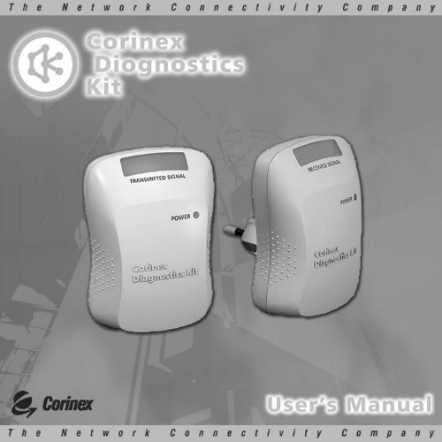
About Corinex Diagnostics Kit1About Corinex Diagnostics KitThe Corinex Diagnostics Kit (CXDK) provides the possibility to measure the levelof connectivity between electrical wall outlets in premises for the potential use ina powerline network. CXDK is a pair of two devices; a Transmitter and a Receiver(Picture 1).3Picture 1 - Transmitter and Receiver Units
About Corinex Diagnostics Kit1.1 TransmitterThe transmitter broadcasts a signal in a frequency bandwidth similar to a CorinexIntelligent PowerNet device or any other HomePlug compatible powerline device.The signal is transmitted over a time period of two seconds into the powerline network.The signal may be introduced from any randomly chosen electrical outlet.After the Corinex Diagnostics Kit Transmitter has been plugged into one electrical outletit begins automatically to transmit the signal into the powerline. This activity is confirmedby the illumination of a green LED on top of the CXDK Transmitter (see Figure 2).A red LED, placed in the middle of the housing, shows that power supply is present.If there is no illuminated red light, this outlet is without electricity.4Picture 2 - Top of Corinex Diagnostics Kit Transmitter
About Corinex Diagnostics Kit1.2 ReceiverThe CXDK Receiver recognizes all signal activity on the powerline. This means, that theCXDK Receiver does receive not only the productive signal from the Transmitter, but alsopotential electrical noise. This does however not influence the answers the user is lookingfor, which is connectivity or no connectivity between two measured outlets.The CXDK Receiver can be plugged into any other randomly chosen electrical outlet,which should be different from the outlet chosen for the Transmitter.The receiver of the Corinex Diagnostics kit displays the connectivity and the permeabilityof the broadcasted signal over the powerline network between the two chosen electricaloutlets. The level of strength of the received signal is shown in the display on top of theCXDK Receiver by eight green LEDs.A red LED in the center of the housing of the CXDK Receiver shows, whether electricalpower is present. If there is no red illuminated light, this means, that this measuredoutlet is without electricity.5
Measurement Instructions2Measurement Instructions!Warning!During the measurement process it is necessary to disconnectall other powerline communication devices on the network. Thesignal which is transmitted from other powerline communicationsdevices will influence the accuracy of the measurement.Preparation stage: for a quick and effective measurement, the user will have prepared adrawing of the rooms he wants to measure and the placement / location of the electricaloutlets in the rooms. It is considered a good idea, to have the drawing available onpaper in form of a truth table, which allows to take a quick note of the result of themeasurement for each electrical outlet.6The fastest way to results is obtained by choosing two electrical outlets, for which apowerline communication link is foreseen. Corinex recommends to make two differentmeasurements: first for the evaluation of the measurement of the noise level in thepowerline, second the evaluation of the connectivity and the permeability of thebroadcasted signal over the powerline network.First measurement – noise level. Plug the CXDK Receiver into a chosen electrical outlet.Red LED (with label POWER) is immediately alight. If there is no red light, this means thatthis outlet is without electricity.On top of the CXDK Receiver (see Figure 2) are eight green LED’s. If there is noise on thepowerline, some of these LED’s will start blinking. This noise on the powerline will havesome influence on the quality of the connectivity and the permeability of the
Measurement Instructionspowerline network. This does however not influence the decision to use the outlet forcommunications or not. It is just an indicator and statement of fact, which may explainwhy the user will find different performance measures for connectivity between severaloutlets, he plans to use for powerline communications purposes.Second measurement – The connectivity and permeability level. This stage is similar tothe first measurement; however the user needs to plug the Transmitter into the secondelectrical outlet. The red LED, with the label POWER, should light up immediately. Ifthere is no red light, this means, that this outlet is without electricity. At the same time,the green LED on top of the CXDK receiver starts blinking with 2 sec periodic intervals.There are eight LEDs and the number of blinking green LED lights on the receiver showsthe strength of the connectivity and the permeability of the powerline network betweenthese two measured electrical outlets.Table 1 shows a comparison of a number of green LED’s and the strength of theconnectivity and the permeability.7
Measurement Results3Measurement Results!Warning!Table 1: All numbers represent an estimated value, based uponrelativity to true measurements, executed with more sophisticatedequipment.Certain types of distortion, like line filters etc., may causediagnostics results (only 1 or 2 LEDs alight, as an indicator for aslow connection) which are not relevant and do not reflect thereal communication speeds achieved, when the HomePlug basedpowerline adapters get used. The real results will be better thanthe indicator suggests.8Estimated communication speedNumber of green LED Signal attenuation [dB][Mbps]1 48 02 42 up to 23 36 54 30 55 - 8 0-24 6Table 1Comparison of number of green LED’s alight and the connectivity and permeability of theelectrical line between the two measured outlets.
Specifications4SpecificationsPower supply 110-240V AC 0,05AStandard compliance• CE / CB marks for European markets• FCC / UL (UL-C) marks for the US marketEMC FCC part 15Operating TemperatureStorage TemperatureLED status32°F to 131°F (0° to 55°C)-4°F to 158°F (-20° to 70°C)Power, Level of signal strength9
Contact Us5Contact UsNorth America:Corinex Communications Corp.World Trade Center404-999 Canada PlaceVancouver, B.C.Canada V6C 3E2Phone: +1 (604) 692-0520Fax: +1 (604) 694-0061E-mail: global@corinex.comEurope:Corinex Global a.s.Ruzova dolina 19821 08 BratislavaSlovak RepublicPhone: +421 2 5021 4811Fax: +421 2 5556 7309E-mail: global_europe@corinex.com10Visit our Web Site: www.corinex.com


