James Wingert, Rigaku SmartLab XRD Specs
James Wingert, Rigaku SmartLab XRD Specs
James Wingert, Rigaku SmartLab XRD Specs
- No tags were found...

You also want an ePaper? Increase the reach of your titles
YUMPU automatically turns print PDFs into web optimized ePapers that Google loves.
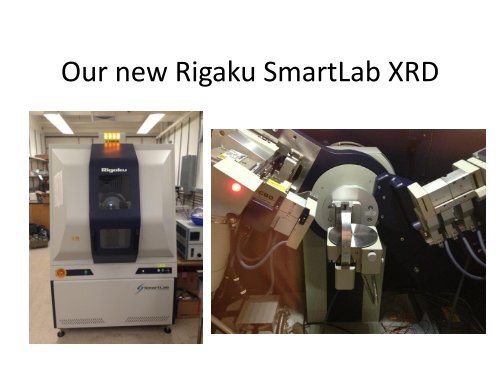
Our new <strong>Rigaku</strong> <strong>SmartLab</strong> <strong>XRD</strong>
Source• Standard Copper anode sealed tube sourcewith Tungsten filament.• Maximum power of 3 kW. Typically run at1.76 kW (44 kV, 40 mA) to maximize life ofanode.• Primary beam is 0.4 mm (vertical) x 12 mm(horizontal)
Bragg-Brentano (BB) vs. Parallel Beam (PB)selection slits• BB simply allows the beam to diverge• PB uses a multilayer mirror to produce a (vertically) parallelbeam. Still some slight divergence (~0.01°)• Usually about 5° divergence horizontally (determined by sollerslits)
“PSA” and “PSC”• = parallel slit analyzer (PSA) and parallel slitcollimator (PSC). C=incident side, A=receiving.• Same construction as a soller slit, but foils areoriented perpendicular to plane of diffraction.• In contrast to soller slits, these actuallydetermine resolution of measurement. (Twooptions are 0.5° and 0.114°)• Finite width of foils reduces intensity.
Receiving and Incident Slits• One incident slit and two receiving slits are computer controlled.• The two receiving slits should be as narrow as possible (0.03 mmmin) to achieve maximum resolution.• Very large reduction in intensity requires long counting times iflooking at Bragg reflections.• Narrow slits ideal if measuring reflectivity or total externalreflection.• In contrast to using PSA to limit resolution, slits can introduce apeak shift if sample height is inaccurately determined.http://www.stanford.edu/group/glam/xlab/MatSci162_172/LectureNotes/06_Geometry,%20Detectors.pdf
Monochromators/Filters• A Ge monochromator (220 orientation, 2 bounce)is optional on incident beam side. This selectsout only Kα1 radiation but at the expense ofintensity. Typically just used for singlecrystals/thin films.• Graphite monochromator optional on receivingside. Will eliminate Kβ but not Kα2 radiation.• Kβ filter is a simple Nickel plate on receiving side.Nickel has a band edge between Kα and Kβenergies. Reduces intensity ~ 30%.
Detector• NaI scintillation point detector.• Linear to about 500,000 cps. Automatic andmanual attenuation options.From http://www4.nau.edu/microanalysis/Microprobe/WDS-Scintillation.html
Sample Alignment• Software has preset and adjustable algorithmsfor sample alignment.• Typical alignment: Adjust height (Z) to achievedirect beam half intensity, adjustsource/detector axis (ω) to maximize intensityat optimal Z. Finally, adjust Z again whenmeasuring a small-angle reflection (~0.5°) toachieve max intensity.
Sample Stages• 3 stages available.• Standard stage: Flat,required to mount aspecial slit used for aligningoptics. Also adequate forbasic powder diffraction.• Euler Cradle: Allowsadjustment of χ and φ • Anton Paar: LN2temperature control from~85K to 450° C. Noadjustment of χ and φ(Courtesy JIMgraphics)