4059 G - Absolute Process Instruments
4059 G - Absolute Process Instruments
4059 G - Absolute Process Instruments

You also want an ePaper? Increase the reach of your titles
YUMPU automatically turns print PDFs into web optimized ePapers that Google loves.
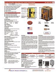
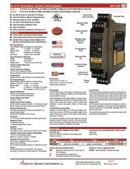
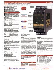
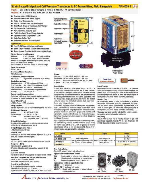
Strain Gauge/Bridge/Load Cell/Pressure Transducer to DC Transmitters, Field RangeableInput:One to Four 350 W Sensors, 0-5 mV to 0-400 mV, 4-10 VDC ExcitationOutput: 0-1 V to ±10 V or 0-1 mA to 4-20 mA, IsolatedOODrive up to Four 350 Ω BridgesOOAdjustable Excitation Power SupplyOOSense Lead CompensationOOEasy to Cancel or Tare Out DeadweightsOOOne Minute Setup for Hundreds of I/O RangesOOHot-Swappable Plug-In DesignOONon-Interactive Zero and SpanOOFull 3-Way Input/Output/Power IsolationOOInput and Output LoopTracker ® LEDsOOAdjustable Output TestOOExternal Calibration Resistor OptionApplicationsQQLoad Cell Weighing Systems and ScalesQQStrain Gauge Pressure Sensors and TransducersQQTanks, Scales, Extruder Melt Pressure, Crane LoadsStrain Gauge Input RangesMinimum: 0 to 5 mV range 0.5 mV/V sensitivityMaximum: 0 to 400 mV range 40 mV/V sensitivityMillivolt output range is determined by the sensor sensitivity(mV/V) and the excitation voltage:mV/V sensitivity X excitation voltage = total mV rangeInput Impedance200 kΩ typicalCommon Mode Rejection100 dB minimumCalibration Resistor OptionM02 option: Toggle switch for external shunt resistorExcitation VoltageMaximum output: 10 VDC maximum at 120 mADrive capability: Up to four 350 Ω bridges at 10 VDCSwitch-selectable: 0-10 VDC in 1 V incrementsFine adjustment: ±5% via multi-turn potentiometerStability: ±0.01% per °CSense Lead CompensationBetter than ±0.01% per 1 W change in leadwire resistance.10 W max. for 10 VDC excitation w. 350 W bridgeZero Offset (Tare)±100% of span in 15% incrementsLoopTrackerVariable brightness LEDs for input/output loop level and statusDC Output RangesVoltage: 0-1 VDC to 0-10 VDCBipolar voltage: ±1 VDC to ±10 VDCCurrent: 0-2 mADC to 0-25 mADC20 V compliance, 1000 W at 20 mAOutput CalibrationNon-interactive multi-turn zero and span potentiometers±15% of span adjustment range typicalOutput Ripple and Noise
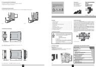
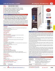
50808080InstructionsInstallation PrecautionsWARNING! All wiring must be performed by a qualified electrician orinstrumentation engineer. Consult factory for assistance.The module is designed to be mounted in a housing or panel. Mountthe socket to a 35 mm DIN rail or suitable surface.Avoid shock hazards! Turn signal input, output, and power off beforeconnecting or disconnecting wiring. Connect power last.Input TerminalsRefer to diagram below and strain gauge manufacturer’s data sheetfor wiring and color coding. Polarity must be observed when connectinginputs. Connect up to 4 strain gauges or load cells. Sensorshield wire (if equipped) should be grounded at one end only.Excitation Voltage ConnectionPolarity must be observed. Never short the excitation leads together.This will cause internal damage to the module.Sense LeadsConnect the sense leads as shown. If no sense leads are used,jumper terminals 6 and 7.Signal Output TerminalsPolarity must be observed when connecting the signal output.Current output provides power to the output loop (sourcing).Module Power TerminalsThe module operating voltage shown on the white model/serialnumber label must match available power. AC power can beconnected with either polarity. Polarity MUST be observed for DCpowered modules.Load cellwith built-incalibrationresistorused withM02 optionSockettop viewKey downwhen panelmountingExc. (–)Excitation Voltage and Range SelectionThe API <strong>4059</strong> G excitation voltage, input, and output are switchselectable via 4 rotary switches and a slide switch on the side of themodule. Common ranges are listed on the module label.Excitation Fine AdjustVolt/CurrExcitationSelectI V Output Offset RangeA B C D E64VEX –V0 –31. See table below and set Excitation rotary switch C to the desiredvoltage. The excitation voltage should match the sensor manufacturer’srecommendations.Excitation 10V 9V 8V 7V 6V 5V 4V 3V 2V 1V 0VSwitch C A 9 8 7 6 5 4 3 2 1 078291A9765V0 +VEX +8 7 6 5 49 10 11 1 2 3To M02calibrationresistor switchModuleOutput (+) (–) powerWhen using themA output the API<strong>4059</strong> G provides20 V loop powerSense (–)Exc. (+)PLC,Display,Recorder,Etc.Sense (+)Sense –PowerAC orDC+BC4D3ESig. (–)F127A965Sig. (+)PowerAC orDC–BC4D3EF12Straingauge7Jumper6 and 7ONLY ifsenseleads areNOT usedA96B5C4D3EF12<strong>4059</strong>G2. Set Volt/Curr slide switch A to voltage “V” or current “I” dependingon output type.3. From the table above, find the rotary switch combination thatmatch your I/O range and set rotary switches B, D, and E.CalibrationTop-mounted Zero and Span potentiometers are used to fine-tunethe output signal. An excitation voltage fine adjust potentiometer islocated on the side of the module.This procedure and does not account for offset or tare weightcalibration. To achieve optimum results, it is recommended that theAPI <strong>4059</strong> G be calibrated using an accurate bridge simulator beforebeing placed in service.1. Apply power to the module and allow a minimum 20 minutewarm up time.2. Using an accurate voltmeter across terminals 7 and 8, adjust theexcitation voltage fine adjust potentiometer for the exact outputdesired.3. Provide an input to the module equal to zero or the minimuminput required for the application.4. Using an accurate measurement device for the module output,adjust the Zero potentiometer for the exact minimum outputdesired. The Zero control should only be adjusted when theinput signal is at its minimum. This will produce the correspondingminimum output signal.5. Set the input at maximum, and then adjust the Span pot for theexact maximum output desired. The Span control should onlybe adjusted when the input signal is at its maximum. This willproduce the corresponding maximum output signal.6. The calibration procedure should be repeated to achieve thedesired accuracy over the selected range.Using Offset Switch DOffset switch D can be used to cancel or tare non-zero readingsby offsetting the low end of the input range. This can be used tocompensate for tare weights or scale deadweight to get zero outputwhen a load is on the platform. It can be used to compensate forlow-output sensors (e.g., less than 1 mV/V) that may have largezero offsets. Switch D can realign the zero control so it has enoughrange to produce the desired zero output. It can also raise the offsetto allow calibration of bipolar sensors such as ±10 mV or lower theoffset to compensate for elevated input ranges such as 10-20 mV.1. Switch D does not interact with any other switch and is theonly switch needed to correct zero offsets. Its only purpose isto adjust or cancel effects of the low end of the input range notcorresponding nominally to 0 mV. Setting switch D to “0” resultsin no offset.2. To raise the output zero, rotate switch D clockwise from 1through 7 until the zero potentiometer is within range of yourdesired output.3. To lower the output zero, rotate switch D through ranges 9through F until the zero potentiometer is within range of yourdesired output. This range is often used for elevated inputranges.Calibration Resistor Option M02The M02 option is specified when the transducer incorporates acalibration resistor. The transducer must be connected as per themanufacturer’s specifications. The transducer’s calibration resistorwires are connected to terminals 5 and 11 on the API <strong>4059</strong> Gsocket. See wiring diagram.The sensor manufacturer should provide the percentage of fullscaletransducer output when using the internal calibration resistor.1. With the API <strong>4059</strong> G powered and the transducer at operatingAPI <strong>4059</strong> GOutput0-1 0-2 0-4 1-5 0-5 0-8 2-10 0-10 ±5 ±10 0-2 2-10 0-10 0-16 4-20 0-20V V V V V V V V V V mA mA mA mA mA mASwitchesABDE ABDE ABDE ABDE ABDE ABDE ABDE ABDE ABDE ABDE ABDE ABDE ABDE ABDE ABDE ABDEInput0-5 mV V002 V802 V102 V602 V902 V202 V702 V302 V402 V502 I007 I602 I902 I202 I702 I302±10 mV V033 V833 V133 V633 V933 V233 V733 V333 V433 V533 I033 I633 I933 I233 I733 I3330-10 mV V00A V80A V10A V60A V90A V20A V70A V30A V40A V50A I00A I60A I90A I20A I70A I30A±20 mV V03B V83B V13B V63B V93B V23B V73B V33B V43B V53B I03B I63B I93B I23B I73B I33B0-20 mV V003 V803 V103 V603 V903 V203 V703 V303 V403 V503 I003 I603 I903 I203 I703 I3030-25 mV V006 V806 V106 V606 V906 V206 V706 V306 V406 V506 I006 I606 I906 I206 I706 I3060-30 mV V00E V80E V10E V60E V90E V20E V70E V30E V40E V50E I00E I60E I90E I20E I70E I30E0-40 mV V00B V80B V10B V60B V90B V20B V70B V30B V40B V50B I00B I60B I90B I20B I70B I30B0-50 mV V000 V800 V100 V600 V900 V200 V700 V300 V400 V500 I000 I600 I900 I200 I700 I3000-100 mV V008 V808 V108 V608 V908 V208 V708 V308 V408 V508 I008 I608 I908 I208 I708 I3080-200 mV V001 V801 V101 V601 V901 V201 V701 V301 V401 V501 I001 I601 I901 I201 I701 I3010-250 mV V004 V804 V104 V604 V904 V204 V704 V304 V404 V504 I004 I604 I904 I204 I704 I3040-300 mV V00C V80C V10C V60C V90C V20C V70C V30C V40C V50C I00C I60C I90C I20C I70C I30C0-400 mV V009 V809 V109 V609 V909 V209 V709 V309 V409 V509 I009 I609 I909 I209 I709 I309temperature, adjust the zero pot for a zero or low-end output,e.g. 4 mA (assuming the selected output is 4-20 mA).2. The zero pot may also be adjusted for a zero reading on theoutput display instrumentation, e.g. control system or processindicator. Adjusting the zero pot this way eliminates calibrationerrors in the display instrumentation.3. Set the API <strong>4059</strong> G Test toggle switch to the Test position. Thetransducer’s shunt resistor is switched into the circuit to unbalancethe bridge.4. Adjust the span pot for an 80% FS output or 80% reading onthe process indicator, or per the manufacturer’s percentage of FSoutput.5. Return the Test switch to the opposite position and readjust thezero pot if necessary.Output Test FunctionNote that models with the M02 option do not have a TEST function.With this option the Test switch operates the calibration resistor andthe Test Cal. potentiometer is non-functional.The output test potentiometer is factory set to provide approximately50% output. When the test button is depressed it will drive theoutput with a known good signal that can be used as a diagnosticaid during initial start-up or troubleshooting. When released, theoutput will return to normal.The Test Cal. potentiometer can be used to set the test output tothe desired level. It is adjustable from 0 to 100% of the output span.Press and hold the Test button and adjust the Test Cal. potentiometerfor the desired output level.OperationStrain gauges and load cells are normally passive devices thatare commonly referred to as bridges due to their four-resistorWheatstone bridge configuration. These sensors require a preciseexcitation source to produce an output that is directly proportionalto the load, pressure, etc. that is applied to the sensor.The exact output of the sensor (measured in millivolts) is determinedby the sensitivity of the sensor (mV/V) and the excitationvoltage applied. For example, a load cell rated for 3 mV/V sensitivityand 10 VDC excitation will produce an output of 0 to 30 mV for loadvariations from 0 to 100%.3 mV/V sensitivity X 10 VDC excitation = 30 mV rangeThe API <strong>4059</strong> G provides a precise excitation voltage to the sensorsand receives the resulting millivolt signal in return. This input signalis filtered and amplified, then offset, if required, and passed to theoutput stage. Depending on the output configuration selected, a DCvoltage or current output is generated.GREEN LoopTracker ® Input LED – Provides a visual indicationthat a signal is being sensed by the input circuitry of the module. Italso indicates the input signal level by changing in intensity as theprocess changes from minimum to maximum. If the LED fails to illuminate,or fails to change in intensity as the process changes, thismay indicate a problem with module power or signal input wiring.RED LoopTracker Output LED – Provides a visual indication thatthe output signal is functioning. It becomes brighter as the inputand the corresponding output change from minimum to maximum.For current outputs, the RED LED will only light if the output loopcurrent path is complete. For either current or voltage outputs,failure to illuminate or a failure to change in intensity as the processchanges may indicate a problem with the module power or signaloutput wiring.API maintains a constant effort to upgrade and improve its products.Specifications are subject to change without notice. Contact factoryfor assistance and see api-usa.com for latest datasheet version.BSOLUTE ROCESS NSTRUMENTS, Inc.1220 American Way Libertyville, IL 60048Phone: 800-942-0315 Fax: 800-949-7502api-usa.com