FSP180-50LE Main Feature Active PFC Circuit Full Range Input
FSP180-50LE Main Feature Active PFC Circuit Full Range Input
FSP180-50LE Main Feature Active PFC Circuit Full Range Input

Create successful ePaper yourself
Turn your PDF publications into a flip-book with our unique Google optimized e-Paper software.
1. GENERAL DESCRIPTION AND SCOPE<br />
This is the specification of Model <strong>FSP180</strong>-<strong>50LE</strong>; AC-line powered switching power supply with<br />
active <strong>PFC</strong> (Power Factor Correction) circuit, meet EN61000-3-2 and with <strong>Full</strong> <strong>Range</strong> <strong>Input</strong><br />
features. Designed and manufactured by FSP GROUP.<br />
The specification below is intended to describe as detailedly as possible the functions and<br />
performance of the subject power supply. Any comment or additional requirements to this<br />
specification from our customers will be highly appreciated and treated as a new target for us<br />
to approach.<br />
2. REFERENCE DOCUMENTS<br />
The subject power supply will meet the EMI requirements and obtain main safety approvals<br />
as following:<br />
2.1 EMI REGULATORY<br />
- FCC Part 15 Subpart J, Class ‘B’ 115 Vac operation.<br />
- CISPR 22 Class ‘B’ 230 Vac operation.<br />
2.2 SAFETY<br />
- NEMKO EN 60950-1<br />
- TUV EN60950<br />
- CSA-C22.2 NO. 60950-1<br />
- IEC 60950-1<br />
- UL 60950-1<br />
- CE<br />
EN 55022:1998+A1: 2000, Class B<br />
EN 61000-3-2: 2000<br />
EN 61000-3-3: 1995+A1: 2001<br />
CISPR22: 1997+A1: 2000, Class B<br />
AS/NZS CISPR 22: 2002, Class B<br />
EN 55024: 1998+A1: 2001<br />
3<br />
IEC 61000-4-2: 2001<br />
IEC 61000-4-3: 2002<br />
IEC 61000-4-4:1995<br />
+A1:2000+A2: 2001<br />
IEC 61000-4-5: 2001<br />
IEC 61000-4-6: 2001<br />
IEC 61000-4-8: 2001
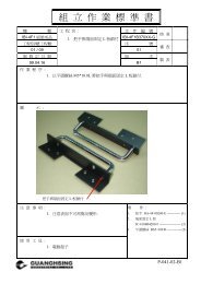
3. PHYSICAL REQUIREMENTS<br />
3.1 MECHANICAL SPECIFICATIONS<br />
The mechanical drawing of the subject power supply, which indicate the form factor, location of<br />
the mounting holes, location, the length of the connectors, and other physical specifications of the<br />
subject power supply. Please refer to the attachment drawing.<br />
3.2 CONNECTOR SPECIFICATIONS<br />
The power supply connectors are:<br />
AC Inlet : Standard inlet socket 10A/250V, UL/CSA/VDE approved.<br />
P1 : The equivalent of MOLEX 39-01-2200, 20 pin connector.<br />
PA,PC,PD : The equivalent of AMP 1-480424-0, 4 pin connector.<br />
PB : The equivalent of AMP 171822-4, 4 pin connector.<br />
PE : The equivalent of MOLEX 39-01-2040, 4 pin connector.<br />
3.3 CONNECTOR PIN DESIGNATIONS<br />
The pin designations and color codes are defined as follows:<br />
P1<br />
SYSTEM BOARD<br />
PA,PC,PD<br />
4<br />
PB<br />
PE<br />
DISK DRIVER<br />
DISK DRIVER DISK DRIVER<br />
PIN1 +3.3V ORANGE +12V YELLOW +12V YELLOW COM BLACK<br />
PIN2 +3.3V ORANGE COM BLACK COM BLACK COM BLACK<br />
PIN3 COM BLACK COM BLACK COM BLACK +12V YELLOW<br />
PIN4 +5V RED +5V RED +5V RED +12V YELLOW<br />
PIN5 COM BLACK<br />
PIN6 +5V RED<br />
PIN7 COM BLACK<br />
PIN8 PW-OK GRAY<br />
PIN9 +5Vsb PURPLE<br />
PIN10 +12V YELLOW<br />
PIN11<br />
+3.3V<br />
+3.3VS<br />
ORANGE<br />
BROWN<br />
PIN12 -12V BLUE<br />
PIN13 COM BLACK<br />
PIN14 PS-ON GREEN<br />
PIN15 COM BLACK<br />
PIN16 COM BLACK<br />
PIN17 COM BLACK<br />
PIN18 NC NC<br />
PIN19 +5V RED<br />
PIN20 +5V RED
4.1.4.OUTPUT RISE TIME<br />
(10% TO 90% OF FINAL OUTPUT VALUE, @FULL LOAD)<br />
115V-rms or 230V-rms + 5Vdc : 20ms Maximum<br />
4.1.5.OVER VOLTAGE PROTECTION<br />
+5V dc output: +5.7 V dc minimum, + 6.5V dc maximum<br />
+12Vdc output: +13.3Vdc minimum , + 15.6V dc maximum<br />
+ 3.3V dc output: +3.7Vdc minimum , + 4.5V dc maximum<br />
4.1.6.SHORT CIRCUIT PROTECTION<br />
Output short circuit is defined to be a short circuit load of less than 0.1 ohm.<br />
In the event of an output short circuit condition on +3.3V, +5V or +12V output, the power supply<br />
will shutdown and latch off. The power supply shall return to normal operation after the short<br />
circuit has been removed and the power switch has been turned off for no more than 2 seconds.<br />
In the event of an output short circuit condition –12V output, the power supply will not be latch off.<br />
The power supply shall return to normal operation as soon as the short circuit has been removed and<br />
the power switch has been turned off for no more than 2 seconds.<br />
4.1.7.OVERLOAD PROTECTION<br />
Overload currents defined as a 10 amp/sec fault current ramp starting from full load, applied to the<br />
+3.3V, +5V output, shall not cause that output to exceed 35 amps before the output voltage drops<br />
below 0.5 volts and is latched off. The +12V output shall not exceed 25 amps under the same ramp<br />
conditions starting at full load before it is latched off.<br />
4.1.8.POWER GOOD SIGNAL<br />
The power good signal is a TTL compatible signal for the purpose of initiating an orderly star-up<br />
procedure under normal input operating conditions. This signal is asserted (low) until +5Vdc has<br />
reached 4.75 volts during power up. Characteristics:<br />
TTL signal asserted (low state) : less than 0.5V while sinking 10mA.<br />
6
5.3. VIBRATION<br />
The subject power supplies will withstand the following imposed conditions without experiencing<br />
non-recoverable failure or deviation from specified output characteristics.<br />
Vibration Operating – Sine wave excited, 0.5 G maximum acceleration, 10-250 Hz swept at one<br />
octave / min. Fifteen minute dwell at all resonant points, where resonance is defined as those<br />
exciting frequencies at which the device under test experiences excursions two times large than<br />
non-resonant excursions.<br />
Plane of vibration to be along three mutually perpendicular axes.<br />
5.4. SHOCK<br />
The subject power supplies will withstand the following imposed conditions without experiencing<br />
non-recoverable failure or deviation from specified output characteristics.<br />
Storage –40G, 11 mSec. half-sine wave pulse in both directions on three mutually<br />
perpendicular axes.<br />
Operating -10G, 11mSec. half-sine wave pulse in both directions on three mutually<br />
Perpendicular axes.<br />
5.5 COOLING SPECIFICATIONS<br />
5.5.1. The PS is cooled by a self-contained, 40mm, 12VDC.<br />
6. SAFETY<br />
6.1. LEAKAGE CURRENT<br />
The leakage current from AC to safety ground will not exceed 3.5 mA-rms at 264Vac, 50 Hz.<br />
7. ELECTORMAGNETIC COMPATIBILITY<br />
7.1 LINE CONDUCTED EMI<br />
The subject power supplies will meet FCC and VFG class B requirements .<br />
10