CHAPTER 13 OBJECT-ORIENTED ANALYSIS
CHAPTER 13 OBJECT-ORIENTED ANALYSIS
CHAPTER 13 OBJECT-ORIENTED ANALYSIS
- No tags were found...

You also want an ePaper? Increase the reach of your titles
YUMPU automatically turns print PDFs into web optimized ePapers that Google loves.
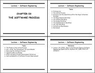
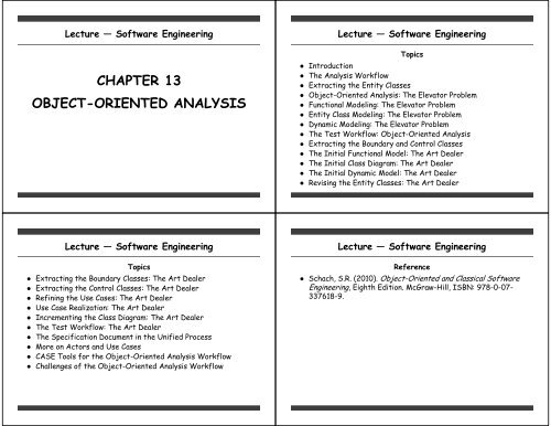
Lecture — Software Engineering<strong>CHAPTER</strong> <strong>13</strong><strong>OBJECT</strong>-<strong>ORIENTED</strong> <strong>ANALYSIS</strong>Lecture — Software EngineeringTopics● Introduction● The Analysis Workflow● Extracting the Entity Classes● Object-Oriented Analysis: The Elevator Problem● Functional Modeling: The Elevator Problem● Entity Class Modeling: The Elevator Problem● Dynamic Modeling: The Elevator Problem● The Test Workflow: Object-Oriented Analysis● Extracting the Boundary and Control Classes● The Initial Functional Model: The Art Dealer● The Initial Class Diagram: The Art Dealer● The Initial Dynamic Model: The Art Dealer● Revising the Entity Classes: The Art DealerLecture — Software EngineeringTopics● Extracting the Boundary Classes: The Art Dealer● Extracting the Control Classes: The Art Dealer● Refining the Use Cases: The Art Dealer● Use Case Realization: The Art Dealer● Incrementing the Class Diagram: The Art Dealer● The Test Workflow: The Art Dealer● The Specification Document in the Unified Process● More on Actors and Use Cases● CASE Tools for the Object-Oriented Analysis Workflow● Challenges of the Object-Oriented Analysis WorkflowLecture — Software EngineeringReference● Schach, S.R. (2010). Object-Oriented and Classical SoftwareEngineering, Eighth Edition. McGraw-Hill, ISBN: 978-0-07-337618-9.
Introduction● Object-oriented analysis (OOA) — A semiformal analysistechnique for object-oriented paradigm● Over 60 different techniques proposed: Largely equivalent● Today Unified Process is almost always methodology of choicefor object-oriented software production● Millennium bug (Y2K problem)• Major advances in object-oriented paradigm: 1990 and 1995• Usually 15 years for new technology to become accepted• Wide-spread adoption should have been 2005• Y2K changed expected timetable• Managers wanted to use modern technology that was costeffective: Object-oriented paradigm• Y2K problem: Significant catalyst for widespread acceptance ofobject-oriented paradigmIntroduction● When analysis workflow is performed: Classes are extracted● Use cases and classes: Basis of object-oriented softwareproductThe Analysis Workflow● Analysis workflow of Unified Process has two aims• To obtain a deeper understanding of requirements• To describe those requirements in such a way that resultingdesign and implementation are easy to maintain● Unified Process is use case driven● During analysis workflow: Use cases are described in terms ofclasses of software product● Unified Process has three types of classes● Entity Class — Models information that is long lived• e.g., Painting Class● Boundary class — Models interaction between softwareproduct and its actors: Generally input and output• e.g., Purchases Report Class● Control Class — Models complex computations and algorithms• e.g., Compute MasterPiece Price ClassThe Analysis Workflow● UML notation for these three types of classes● Stereotypes — Extensions of UML● Additional constructs to be defined to model a specificsystem accurately● Figure <strong>13</strong>.1
The Analysis Workflow● During analysis workflow: Use cases are described in terms ofclasses of the software product● Unified Process does not describe how classes are to beextracted● Users are expected to have a background in object-orientedanalysis and design● Explanation provided of how classes are extractedExtracting the Entity Classes● Entity class extraction consists of three steps: Carried outiteratively and incrementally(1)Functional modeling — Present scenarios of all use cases• Scenario — An instant of a use case(2) Entity class modeling — Determine entity classes and theirattributes• Then determine interrelationships and interactions betweenentity classes• Present this information in form of a class diagram(3) Dynamic modeling — Determine operations performed by orto each entity class or subclass• Present information in form of a statechart● Three steps are not necessarily performed in order: A changein one model frequently triggers corresponding revisions ofother two modelsObject-Oriented Analysis: The Elevator Problem● Steps of object-oriented analysis are applied to elevatorproblemFunctional Modeling: The Elevator Problem● Use case describes interaction between product and actors● Use case provides a generic description of overallfunctionality● Only interactions possible between a user and an elevator• User pressing an elevator button: Press an Elevator Button usecase• User pressing a floor button: Press a Floor Button use case● Scenario — A specific instantiation of a use case● There are a large number of scenarios● Each representing one specific set of interactions
Functional Modeling: The Elevator Problem● Figure <strong>13</strong>.2Functional Modeling: The Elevator Problem● Normal scenario — Set of interactions between users andelevators that correspond to the way elevators areunderstood● Exception scenario — depicts unusual interactions• E.g., pressing up button instead of down button● All scenarios constructed after carefully observing differentusers● Form of statements in a scenario: User does this andsoftware product responds by doing that● Sufficient scenarios should be studied to give the OOA teama comprehensive insight into behavior of system● Information used in next step: Entity class modelingFunctional Modeling: The Elevator Problem● Figure <strong>13</strong>.3Functional Modeling: The Elevator Problem● Figure <strong>13</strong>.4
Entity Class Modeling: The Elevator Problem● In this step: Entity classes and their attributes areextracted and represented in a UML class diagram● Only attributes are determined● Methods are not determined: Assigned to classes duringobject-oriented design workflow● Two approaches to determine entity classes(1) Deduce them from use cases● Developers study normal and exception scenarios● Identify components that play a role in use cases● Entity classes from elevator scenarios• elevator buttons, floor buttons, elevators, doors, and timers• Close to the actual classes● Many scenarios result in a large number of potential classes• Should not infer too many candidate entity classes• Easier to add a new entity class than to remove oneEntity Class Modeling: The Elevator Problem(2) CRC cards● Effective when users have domain expertise● Otherwise: Use noun extractionNoun Extraction● Noun extraction method — Two-stage process to extractcandidate entity classes for developers with no domainexpertise● Stage 1: Describe software product in a single paragraph● Stage 2: Identify the nouns• Identify nouns in informal strategy• Excluding those that lie outside the problem boundary● Use these nouns as candidate entity classes● Informal strategy is reproduced with identified nouns in adifferent typefaceEntity Class Modeling: The Elevator Problem● Buttons in elevators and on the floors control the movementof n elevators in a building with m floors. Buttons illuminatewhen pressed to request the elevator to stop at a specificfloor; the illumination is canceled when the request has beensatisfied. When an elevator has no requests, it remains at itscurrent floor with its doors closedEntity Class Modeling: The Elevator Problem● Eight different nouns in elevator problem● Three lie outside problem boundary: floor, building, and door• May be ignored● Three are abstract nouns: movement, illumination, and request• Things that have no physical existence• Rarely end up corresponding to classes• Frequently are attributes of classes● Two are candidate entity classes: elevator and button● UML convention for class names• Boldface• Capitalize initial letter
Entity Class Modeling: The Elevator Problem● Resulting class diagram● Figure <strong>13</strong>.5Entity Class Modeling: The Elevator Problem● Button class• Boolean attribute illuminated: Model events of scenarios• Two subclasses of Elevator Button and Floor Button● In UML: Open triangle denotes inheritance● Elevator class• Boolean attribute doors open to model events of scenarios• Communicates with the button● In a real elevator: An elevator controller is needed• Button do not communicate directly with elevators● Problem statement makes no mention of a controller: Notselected during noun-extraction process● Adding Elevator Controller class• One-to-many relationship instead of many-to-many (moredifficult)Entity Class Modeling: The Elevator Problem● Figure <strong>13</strong>.6Entity Class Modeling: The Elevator ProblemCRC Cards● Class-responsibility-collaboration (CRC) cards have beenutilized during object-oriented analysis workflow● For each class, software development team fills a card• Name of class• Its functionality (responsibility)• List of other classes it invokes to achieve that functionality(collaboration)● Approach has been extended● Contains attributes and methods of class● Instead of cards, put names of classes on cards• Move around on a white board• Lines are drawn to denote collaboration
Entity Class Modeling: The Elevator Problem● Process automated using CASE tools• E.g., System Architect (includes components for creating andupdating CRC cards on screen● Strengths of CRC• When utilized by a team: Interactions among members canhighlight missing or incorrect fields in a class• Relationships between classes are clarified• A powerful technique: Distribute cards among team members,who act out responsibilities of their classes• Verifying that class diagram is complete and correct● Weakness of CRC• Not effective unless team members have considerableexperience in relevant application domainEntity Class Modeling: The Elevator Problem● Once many of classes and their responsibilities andcollaborations are determined: CRC cards can be used to makesure everything is correctDynamic Modeling: The Elevator Problem● Aim of dynamic modeling: Produce a statechart for each class● A description of target product similar to a finite statemachine● Representation of a UML statechart is less formal● Current versions of OOA are semiformal● It is likely that more formal versions will be developed● First iteration of statechart is constructed from scenarios● Specific events of scenarios are generalized● First iteration of the statechart for Elevator Control classDynamic Modeling: The Elevator Problem● Figure <strong>13</strong>.7
The Test Workflow: Object-Oriented Analysis● Test workflow resumes once functional, entity class, anddynamic models appear to be complete● Review analysis workflow to date● Use of CRC cards● CRC cards are filled in for each of entity classes● CRC cards are deduced from class diagrams and statecharts● Responsibility obtained by listing all operations in statechart● Collaboration determined by examining class diagramThe Test Workflow: Object-Oriented Analysis● First iteration ofCRC card forElevator Controlclass● Figure <strong>13</strong>.8The Test Workflow: Object-Oriented Analysis● CRC cards highlight two major problems with first iteration ofobject-oriented analysis● Responsibilities can be out of place from viewpoint ofresponsibility-driven design and information hiding• E.g., turning buttons on and off instead of sending messages● Classes can be overlooked• E.g., Elevator Doors class● IterationsThe Test Workflow: Object-Oriented Analysis● Seconditeration ofCRC card forElevatorControl class● Figure <strong>13</strong>.9
The Test Workflow: Object-Oriented Analysis● Thirditeration ofclass diagramfor elevatorproblem● Figure <strong>13</strong>.10The Test Workflow: Object-Oriented Analysis● Use case diagram and statecharts reexamined to see if theyneed further refinement● Use case diagram is still adequate● Set of statecharts extended to include additional class● Scenarios updated to reflect these changesThe Test Workflow: Object-Oriented Analysis● Second iteration ofa normal scenariofor elevatorproblem● Figure <strong>13</strong>.11The Test Workflow: Object-Oriented Analysis● Problem with third iteration of class diagram● Elevator Control class exposed to too much information andhas too much control● Anti-pattern architecture — Pattern to be avoided● Distribute the control• Elevator Subcontroller class• Floor Subcontroller class• Scheduler class• Sensor class
The Test Workflow: Object-Oriented Analysis● Fourthiteration ofclassdiagram● Figure <strong>13</strong>.12The Test Workflow: Object-Oriented Analysis● Firstiteration ofstatechartfor ElevatorSubcontrollerclass● Figure <strong>13</strong>.<strong>13</strong>The Test Workflow: Object-Oriented Analysis● First iteration ofCRC card forElevatorSubcontrollerclass● Figure <strong>13</strong>.14The Test Workflow: Object-Oriented Analysis● After all changes made and checked● May be necessary during object-oriented design workflow toreturn to object-oriented analysis workflow● Revise one or more of analysis artifacts
Extracting the Boundary and Control Classes● Boundary classes are usually easy to extract● Each input screen, output screen, and printed report ismodeled by its own boundary class● Boundary class incorporates all various data items and variousoperations● Control classes are usually easy to extract● Each nontrivial computation is modeled by a control classThe Initial Functional Model: The Art Dealer● In functional modeling scenarios of use cases are determined● Art dealer software product● Only user of software product is art dealer● Customer is an actor• Roles of buyer or seller• Two use cases that model buying or selling● Art dealer can use software product in four ways: Resulting infour use casesThe Initial Functional Model: The Art Dealer● Second iteration of use case diagram of art dealer● FigureThe Initial Functional Model: The Art Dealer● Scenarios depict interactions● Possible scenarios of buying a masterpiece● Unnumbered sentences have nothing to do with interactionbetween art dealer and software product● For conciseness: Use cases can be combined into one● Normal and exception scenarios can be combined into anextended scenario● Scenarios are used not only in functional modeling step, butalso are important to dynamic modeling step
The Initial Functional Model: The Art Dealer● FigureThe Initial Functional Model: The Art Dealer● FigureThe Initial Functional Model: The Art Dealer● FigureThe Initial Functional Model: The Art Dealer● Figure
The Initial Class Diagram: The Art Dealer● Aim of entity class modeling step• Extract entity classes• Determine their interrelationships• Find their attributes● Initiated by using the two-stage noun-extraction process• Art dealer case is described in a single paragraph• Nouns in this paragraph are identified● Abstract nouns: effectiveness, process, information• Unlikely to be entity classes● Nouns derived from verbs: buying and selling• Operations of some class● Nouns not long lived: report• Unlikely to be an entity class, more likely to be a boundary class● Four nouns as candidate entity classes: Painting class,Masterpiece class, Masterwork class, and Other Painting classThe Initial Class Diagram: The Art Dealer● First iteration of initial class diagram● Now, interrelationships between these four entity classes areconsidered● Painting class is a base class● Other classes are subclasses of that base class● Second iteration of initial class diagram● FigureThe Initial Class Diagram: The Art Dealer● Studying use cases can lead to additional insights● A masterwork has to have all attributes of a masterpiece● In addition, it may have attributes of its own● Third iteration of initial class diagram● FigureThe Initial Class Diagram: The Art Dealer● Auctioned Painting class● Needed so that a masterpiece can be compared with paintingsauctioned worldwide● Auctioned painting is a painting● Auctioned paintings have nothing to do with paintings ingallery
The Initial Class Diagram: The Art Dealer● Fourth iteration of initial class diagram● FigureThe Initial Class Diagram: The Art Dealer● Fashionability class● A painting of Other Painting class uses instance ofFashionability class for that artist to compute maximum priceThe Initial Class Diagram: The Art Dealer● Fifth iteration of initial class diagram● FigureThe Initial Class Diagram: The Art Dealer● Finally, attributes of each class are added to class diagram● Application class contains attributes and operations ofsoftware product as a whole: Starts execution of wholesoftware product● All other classes contain attributes and operations of varioustypes of paintings
The Initial Class Diagram: The Art Dealer● FigureThe Initial Class Diagram: The Art Dealer● Class diagram is redrawn without attributes, but explicitlyreflecting stereotype of each class● All eight classes are entity classes● A class diagram depicts classes and their interrelationships● Attributes and operations are optionalThe Initial Class Diagram: The Art Dealer● FigureThe Initial Dynamic Model: The Art Dealer● Third step in extracting entity classes is dynamic modeling● A statechart that reflects all operations performed by or tosoftware product is drawn● Major source of information regarding relevant operations isscenarios● Starting point is solid circle on top left● Final state is solid circle inside a circle● Arrow from initial state leads to a state labeled event loop● States other than initial and final states are represented byrectangles with rounded corners
The Initial Dynamic Model: The Art Dealer● FigureThe Initial Dynamic Model: The Art Dealer● One of five events can occur: 4 actions and quit● Event — Something that causes a transition between states● If quit is selected: System moves to its final state● In object-oriented paradigm: There is a dynamic model foreach class● In the art dealer case: There is one for system as a whole● Completed initial functional, entity class, and dynamicmodeling● All three models are checked to be correct, at least for now● Next, boundary classes and control classes are extractedExtracting the Boundary Classes: The Art Dealer● Each input screen, output screen, and printed report is usuallymodeled by a class● One screen to be used for all use cases• Buy a painting, sell a painting, print a report, and update afashionability coefficient● In subsequent iteration: May refine one screen into morescreens● Only one screen class: User Interface Class● First iteration of main menu of user-interface screen● Five commands correspond to five events in statechart● Implementation can use a textual interface instead● Can be run on many computers● GUI generally need special softwareExtracting the Boundary Classes: The Art Dealer● Figure
Extracting the Boundary Classes: The Art Dealer● There are three reports• Purchase report, sales report, future trends report● Each has to be modeled by a separate boundary class: Contentof each report is distinctly different● Resulting four initial boundary classes• User Interface class• Purchase Report class• Sales Report class• Future Trends Report class● FigureExtracting the Control Classes: The Art Dealer● Each nontrivial computation is modeled by a control class● Four computations yield four initial control classes• Compute Masterpiece Price class• Compute Masterwork Price class• Compute Other Painting Price class• Compute Future Trends class● FigureRefining the Use Cases: The Art Dealer● Three sets of classes are checked: Further refinementneeded● Buy a Painting use case refined into three use cases• Buy a Masterpiece• Buy a Masterwork• Buy Other Painting● Produce a Report use case refined into three use cases• Produce a Purchase Report• Produce a Sales Report• Produce a Future Trends ReportRefining the Use Cases: The Art Dealer● Third iteration ofuse case diagram● Figure
Refining the Use Cases: The Art Dealer● Implications of these refinements for other UML diagrams● No reason to have three separate user interfaces to buy apainting● Art dealer has to supply classification to invoke relevantalgorithm● Split description of Buy a Painting use case into threeseparate descriptions● Split description of Produce a Report use case into threeseparate descriptions● Figure● FigureRefining the Use Cases: The Art DealerUse Case Realization: The Art Dealer● Use cases are first utilized at beginning of software life cycle• In requirement workflow● More details are added to each use case• Including a description of classes involved in the use case• During analysis and design workflows● Use case realization — This process of extending and refininguse cases● Use cases are implemented in code• During the implementation workflow● Interaction diagram — Depicts realization of a specificscenario of use case● Two types of interaction diagram• Sequence diagram• Communication diagramUse Case Realization: The Art Dealer● Buy a Masterpiece use case● Classes that realize use case● User Interface class — Models user interface● Compute Masterpiece Price class — Models computation● Involves comparing masterpiece (an instance of Masterpiececlass) with masterpieces previously auctioned (AuctionedPainting class)● Seller does not interact directly with software● Provides data that art dealer enters into software product● Indicated by a note with a dashed line to seller
Use Case Realization: The Art Dealer● A class diagram showing classes that realize use case● FigureUse Case Realization: The Art Dealer● A scenario of use case● FigureUse Case Realization: The Art Dealer● A scenario is one possible instance of a use case● Classes in class diagram have to be able to realize thescenarios● A working software product uses objects rather than classes● A specific masterpiece is represented by an object, a specificinstance of the Masterpiece class● Object denoted by “:Masterpiece” class• Colon denotes an instance of● A class diagram shows classes and their relationship• It shows neither the objects• Nor sequence of messages sent from object to object● A collaboration diagram shows objects as well as messages• Numbered in order in which they are sent in a specific scenario• Direction of arrow shows direction in which information flowsUse Case Realization: The Art Dealer● Client will not approve specification document unless clientunderstands exactly what proposed software will do● Accordingly, a written description of collaboration diagram isneeded: Flow of events
Use Case Realization: The Art Dealer● A collaboration diagram of realization of scenario of use case● FigureUse Case Realization: The Art Dealer● Flow of events of collaboration diagram● FigureUse Case Realization: The Art Dealer● UML supports two different types of interaction diagram• Sequence diagram• Communication diagram (collaboration in older versions)● Both types contain exactly same information, displayed indifferent ways● Developers can choose which to use, or both● Sequence diagram• Lifeline — Vertical line which starts where object is created• Activation box — Narrow rectangle on a life line which showswhen relevant object is active● Sequence diagram equivalent to communication diagram of usecase● FigureUse Case Realization: The Art Dealer
Use Case Realization: The Art Dealer● Strengths of a sequence diagram• Shows flow of information unambiguously• Order of messages is clear• Shows that every transfer of information is followed by atransfer in reverse direction● Choosing between a sequence diagram and a communicationdiagram● Sequence diagram superior when transfer of information isthe focus of attention• Case for much of the time in analysis workflow● communication diagram more useful when developers areconcentrating on classes• Similarity between a class diagram and a collaboration diagramUse Case Realization: The Art Dealer● Buy a Masterwork use case● User Interface class: Models user interface● Compute Masterwork Price class: Models computation of price● Compute Masterpiece Price class: Price of a masterwork isdetermined by first considering it as a masterpiece and thenadjusting result• Creating a masterwork object (instance of Masterwork class)• Passing this object on to Compute Masterpiece Price class● Masterwork class: Instance is created● Auctioned Painting class: Masterpieces previously auctionedare all instance of this classUse Case Realization: The Art Dealer● Cass diagram showing classes that realize Buy a Masterworkuse case● FigureUse Case Realization: The Art Dealer● Scenario for this use case● Figure
Use Case Realization: The Art Dealer● Buy Other Painting use case● User Interface class: Models user interface● FigureUse Case Realization: The Art Dealer● Initial main menu is modified to reflect buying threedifferent types of painting● FigureUse Case Realization: The Art Dealer● Sell a Painting use case● Straightforward as a consequence of simplicity of use case● FigureUse Case Realization: The Art Dealer● Produce a Purchase Report use case and Produce a SalesReport use case● Differ only in output interface class● Browse through Gallery Painting class● Figure
Use Case Realization: The Art Dealer● Produce a Future Trend Report use case• Performs a computation● FigureUse Case Realization: The Art Dealer● Update a Fashionability Coefficient use case● Straightforward● FigureIncrementing the Class Diagram: The Art Dealer● Steps so far• Entity classes are extracted• Boundary classes are extracted• Control classes are extracted• Interrelationships between many of classes became apparent:Shown in class diagrams● Next these class diagrams are combinedIncrementing the Class Diagram: The Art Dealer● Yieldsixthiterationof classdiagram● Figure
Incrementing the Class Diagram: The Art Dealer● Application class and Painting class are added● New relationships are addedIncrementing the Class Diagram: The Art Dealer● Classdiagramat end ofanalysisworkflow● FigureIncrementing the Class Diagram: The Art Dealer● Last step of analysis workflow: Draw up software projectmanagement plan (SPMP)● Adheres to IEEE SPMP formatIncrementing the Class Diagram: The Art Dealer● Figure Appendix
Incrementing the Class Diagram: The Art Dealer● Figure AppendixIncrementing the Class Diagram: The Art Dealer● Figure AppendixIncrementing the Class Diagram: The Art Dealer● Figure AppendixIncrementing the Class Diagram: The Art Dealer● Figure Appendix
Incrementing the Class Diagram: The Art Dealer● Figure AppendixIncrementing the Class Diagram: The Art Dealer● Figure AppendixIncrementing the Class Diagram: The Art Dealer● Figure AppendixIncrementing the Class Diagram: The Art Dealer● Figure Appendix
Incrementing the Class Diagram: The Art Dealer● Figure AppendixIncrementing the Class Diagram: The Art Dealer● Figure AppendixIncrementing the Class Diagram: The Art Dealer● Figure AppendixThe Test Workflow: The Art Dealer● Analysis workflow of art dealer case is checked in two ways(1) Classes are checked using CRC cards(2) All artifacts of analysis workflow are inspected
The Specification Document in the Unified Process● Unified Process is use case driven● Use cases and artifacts derived from them contain allinformation that, in traditional paradigm, appears inspecification document● Convey to client more information more accurately● Collection of artifacts of complete set of productsconstitutes a contract● Traditional specification document usually plays a contractualrole● Interaction diagrams reflecting classes that realize scenariosof the use cases are shown to the client: Instead ofconstructing a rapid prototype● Use cases are successively refined: Rapid prototype generallydiscardedThe Specification Document in the Unified Process● Rapid prototype superior to a scenario in area of userinterface● Does not mean rapid prototype should be built● CASE tools used to generate screens and reportsMore on Actors and Use Cases● How to find actors and use cases● Considering every role in which an individual can interact withsoftware● Extract actors from list of roles● Within a business context, task of finding the roles• Construct use case business model• Finding all roles by individuals who interact with business• Find subset of use case diagram that models software product• Only those parts of business model that correspond to software• Actors in this subset are the actors● Once actors have been determined: Finding use cases isstraightforward● For each role, there are one or more use cases● Starting point in finding use cases of requirement is findingactorsMore on Actors and Use Cases● Summary of how to perform object-oriented analysis● Iterate• Perform functional modeling• Perform entity-class modeling• Perform dynamic modeling● Until entity classes have been satisfactorily extracted● Extract boundary classes and control classes● Refine use cases● Perform use case realization
CASE Tools for the Object-Oriented Analysis Workflow● A number of CASE tools have been developed to supportobject-oriented analysis● Essentially a drawing tool for performing modeling steps● Some CASE tool support graphical aspects of object-orientedanalysis● Some tools also draw CRC cards● A change to underlying model is reflected automatically in allaffected diagrams● Some CASE tools support a considerable portion of objectorientedlife cycle● Nowadays virtually all such tools support UML● E.g., IBM Rational Rose and Together● ArgoUML is an open-source CASE toolChallenges of the Object-Oriented Analysis Workflow● Challenges of classical analysis phase apply equally to objectorientedanalysis● In particular, it is easy to cross the boundary line betweenspecifications and design● Transition from object-oriented analysis to object-orienteddesign far smoother than classical paradigm● Modules are extracted during object-oriented analysisworkflow● Refinement during object-oriented design workflow● Presence of classes can result in carrying OOA too far● Allocation of methods to classes should wait until designworkflow