Metrology Equipment Catalog - Rapp Industrial Sales
Metrology Equipment Catalog - Rapp Industrial Sales
Metrology Equipment Catalog - Rapp Industrial Sales
- No tags were found...

Create successful ePaper yourself
Turn your PDF publications into a flip-book with our unique Google optimized e-Paper software.
I N F O R M AT I O NCheck OutNewProductsAs Brown & Sharpe is constantlyimproving the design of its products,the appearance, specifications,dimensions and weights are subject tochange without notice.©2008 Brown & Sharpe, Inc.,All Rights Reserved.General informationCalipersExternal MicrometersInternal MeasurementMeasuring Instruments for Large DimensionsElectronic Indicators, Dial Gages, Precision IndicatorsLever-type Dial Test IndicatorsComparative MeasurementMeasuring Stands and Auxiliary FixturesStraightness, Angle and Inclination MeasurementLength and Angle StandardsCalibration <strong>Equipment</strong>Surface Roughness TestingHeight GagesElectronic Length Measuring <strong>Equipment</strong>Air Gage Systems for Diameter MeasurementOptical MeasurementCoordinate Measuring MachinesMachinists Tools<strong>Rapp</strong> <strong>Industrial</strong> <strong>Sales</strong>888 789-7277ABCDEFGHIJKLMNOPQRInfo-1
I N F O R M AT I O NI N F O R M AT I O NInfo-2<strong>Rapp</strong> <strong>Industrial</strong> <strong>Sales</strong>888 789-7277
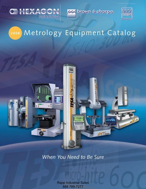
I N F O R M AT I O NI N F O R M AT I O NDear Customer,In looking through the pages of this catalogue, youwill realise that TESA manufactures and marketsworldwide more than 5,000 products ranging fromhigh-precision hand-held measuring instruments tosophisticated measuring systems.Apart from TESA’s futuristic design concept, ourdiversified line of metrology products also reflectsthe advanced technology used for their manufacture.Nearly all are SWISS MADE and provide anoutstanding price/performance relationship.That’s why we at TESA are looking forward toactively supporting you in reaching your objectives ofimproved product quality by offering you customsolutions to meet your specific needs.We thank you for your confidence in our companyand look forward to serving you in the years to come.François GabellaGeneral Manager<strong>Rapp</strong> <strong>Industrial</strong> <strong>Sales</strong>888 789-7277Info-3
2I N F O R M AT I O NI N F O R M AT I O NReading the English MicrometerExample 1A. Barrel GraduationsNumbered lines indicate .100", .200", .300", etc. Each line is .025"B. Thimble GraduationsNumbered lines indicate .001", .002", etc. up to .025"C. DatumLong Line on Barrel 012345678876CAB11439 105Step 1 Highest barrel number . . . . . . . . . . . . . . . . . . . . . . . . . . . . 3 x .100" = .300"Step 2 Number of lines between 3 and edge of thimble. . . . . . . . . 2 x .025" = .050"Step 3 Thimble line closest to long barrel line . . . . . . . . . . . . . . . . 7 x .001" = .007"Total Reading .357"Example 21 0D. Vernier LinesGraduations added 12 on Barrelfor Ten Thousandths0123 456781110987645D1 0765 342 112110123 45678 10901238076451614131211981510Step 1 Follow reading instructions from Example 1. . . . . . . . . . . . . . . . . . . . . . . . . . .357"Step 2 Notice which vernier line coincides with a thimble line . . . . . . . . . . . . . . 2 = .0002"Total Reading .3572"Note: If vernier 0 is coincident with a line on Thimble, the reading is an exactone-thousandth of an inchExample 3 Example 4 Example 5012345678171615 1413121110954 31 0151413120123 45678 97 8611105432 1 02423220123456 78 211181917020Info-10Total Reading - .788"Total Reading - .3321" Total Reading - .6431"<strong>Rapp</strong> <strong>Industrial</strong> <strong>Sales</strong>888 789-7277
I N F O R M AT I O NDecimal EquivalentsDecimal Decimal Decimal Decimal Decimal DecimalSize Inches Size Inches Size Inches Size Inches Size Inches Size Inches97 .005996 .006395 .006794 .007193 .007592 .0079.2 mm .007991 .008390 .0087.22 mm .008789 .009188 .0095.25 mm .009887 .010086 .010585 .0110.28 mm .011084 .0115.3 mm .011883 .012082 .0125.32 mm .012681 .013080 .0135.35 mm .013879 .01451/64 .0156.4 mm .015778 .0160.45 mm .017777 .0180.5 mm .019776 .020075 .0210.55 mm .021774 .0225.6 mm .023673 .024072 .0250.65 mm .025671 .0260.7 mm .027670 .028069 .0292.75 mm .029568 .03101/32 .0312.8 mm .031567 .032066 .0330.85 mm .033565 .0350.9 mm .035464 .036063 .0370.95 mm .037462 .038061 .03901 mm .039460 .040059 .04101.05 mm .041358 .042057 .04301.1 mm .04331.15 mm .045356 .04653/64 .04691.2 mm .04721.25 mm .04921.3 mm .051255 .05201.35 mm .053154 .05501.4 mm .05511.45 mm .05711.5 mm .059153 .05951.55 mm .06101/16 .06251.6 mm .063052 .06351.65 mm .06501.7 mm .066951 .06701.75 mm .068950 .07001.8 mm .07091.85 mm .072849 .07301.9 mm .074848 .07601.95 mm .07685/64 .078147 .07852 mm .07872.05 mm .080746 .081045 .08202.1 mm .08272.15 mm .084644 .08602.2 mm .08662.25 mm .088643 .08902.3 mm .09062.35 mm .092542 .09353/32 .09382.4 mm .094541 .09602.45 mm .096540 .09802.5 mm .098439 .099538 .10152.6 mm .102437 .10402.7 mm .106336 .10652.75 mm .10837/64 .109435 .11002.8 mm .110234 .111033 .11302.9 mm .114232 .11603 mm .118131 .12003.1 mm .12201/8 .12503.2 mm .12603.25 mm .128030 .12853.3 mm .12993.4 mm .133929 .13603.5 mm .137828 .14059/64 .14063.6 mm .141727 .14403.7 mm .145726 .14703.75 mm .147625 .14953.8 mm .149624 .15203.9 mm .153523 .15405/32 .156222 .15704 mm .157521 .159020 .16104.1 mm .16144.2 mm .165419 .16604.25 mm .16734.3 mm .169318 .169511/64 .171917 .17304.4 mm .173216 .17704.5 mm .177215 .18004.6 mm .181114 .182013 .18504.7 mm .18504.75 mm .18703/16 .18754.8 mm .189012 .189011 .19104.9 mm .192910 .19359 .19605 mm .19698 .19905.1 mm .20087 .201013/64 .20316 .20405.2 mm .20475 .20555.25 mm .20675.3 mm .20874 .20905.4 mm .21263 .21305.5 mm .21657/32 .21885.6 mm .22052 .22105.7 mm .22445.75 mm .22641 .22805.8 mm .22835.9 mm .2323A .234015/64 .23446 mm .2362B .23806.1 mm .2402C .24206.2 mm .2441D .24606.25 mm .24616.3 mm .2480E .25001/4 .25006.4 mm .25206.5 mm .2559F .25706.6 mm .2598G .26106.7 mm .263817/64 .26566.75 mm .2657H .26606.8 mm .26776.9 mm .2717I .27207 mm .2756J .27707.1 mm .2795K .28109/32 .28127.2 mm .28357.25 mm .28547.3 mm .2874L .29007.4 mm .2913M .29507.5 mm .295319/64 .29697.6 mm .2992<strong>Rapp</strong> <strong>Industrial</strong> <strong>Sales</strong>888 789-7277N .30207.7 mm .30317.75 mm .30517.8 mm .30717.9 mm .31105/16 .31258 mm .3150O .31608.1 mm .31898.2 mm .3228P .32308.25 mm .32488.3 mm .326821/64 .32818.4 mm .3307Q .33208.5 mm .33468.6 mm .3386R .33908.7 mm .342511/32 .34388.75 mm .34458.8 mm .3465S .34808.9 mm .35049 mm .3543T .35809.1 mm .358323/64 .35949.2 mm .36229.25 mm .36429.3 mm .3661U .36809.4 mm .37019.5 mm .37403/8 .3750V .37709.6 mm .37809.7 mm .38199.75 mm .38399.8 mm .3858W .38609.9 mm .389825/64 .390610 mm .3937X .3970Y .404013/32 .4062Z .413010.5 mm .413427/64 .421911 mm .43317/16 .437511.5 mm .452829/64 .453115/32 .468812 mm .472431/64 .484412.5 mm .49211/2 .500013 mm .511833/64 .515617/32 .531213.5 mm .531535/64 .546914 mm .55129/16 .562514.5 mm .570937/64 .578115 mm .590619/32 .593839/64 .609415.5 mm .61025/8 .625016 mm .629941/64 .640616.5 mm .649621/32 .656217 mm .669343/64 .671911/16 .687517.5 mm .689045/64 .703118 mm .708723/32 .718818.5 mm .728347/64 .734419 mm .74803/4 .750049/64 .765619.5 mm .767725/32 .781220 mm .787451/64 .796920.5 mm .807113/16 .812521 mm .826853/64 .828127/32 .843821.5 mm .846555/64 .859422 mm .86617/8 .875022.5 mm .885857/64 .890623 mm .905529/32 .906259/64 .921923.5 mm .925215/16 .937524 mm .944961/64 .953124.5 mm .964631/32 .968825 mm .984363/64 .98441 1.0000Info-11I N F O R M AT I O N
I N F O R M AT I O NI N F O R M AT I O NReferenceSolving Geometric FiguresTo find the CIRCUMFERENCE OF A CIRCLE,multiply the Diameter by 3.1416The radius of a circle x 6.283185 = thecir cum fer enceTo find the DIAMETER OF A CIRCLE, multiplythe circumference by .31831The square root of the area of a circle x 1.12838= the diameterThe circumference of a circle x .159155 = theradiusThe square root of the area of a circle x .56419= the radiusTo find THE AREA OF A CIRCLE, multiply theSquare of the Diameter by .7854The square of the circumference of a circlex .07958 = the areaHalf the circumference of a circle x half itsdi am e ter = the areaTo find the AREA OF THE SURFACE OF A BALL(SPHERE), multiply the Square of the Diameterby 3.1416To find the VOLUME OF A BALL (SPHERE),multiply the Cube of the Diameter by .5236To find the AREA OF AN ELLIPSE, multiply theLong Diameter by Short Diameter by 0.78540To find the SIDE OF A SQUARE IN SCRIBED IN ACIRCLE, multiply the Diameter by .7071To find the SIDE OF A SQUARE EQUAL INAREA TO A GIVEN CIR CLE, multiply theDiameter by .8862To find the DIAMETER OF A CIRCLE EQUAL INAREA TO A GIVEN SQUARE, multiply a Side ofthe Square by 1.12838To find the SIDE OF A HEXAGON IN SCRIBED INA CIRCLE, multiply the Diameter of the Circle by.500To find the DIAMETER OF A CIRCLEIN SCRIBED IN A HEXAGON, multiply a Sideof the Hexagon by 1.7321To find the SIDE OF AN EQUI LAT ER ALTRI AN GLE INSCRIBED IN A CIRCLE, multiplythe Diameter of the Circle by .866To find the DIAMETER OF A CIRCLEIN SCRIBED IN AN EQUILATERALTRIANGLE, multiply a Side of theTri an gle by .57735To find the AREA OF A SQUARE orRECT AN GLE, multiply the Base by the HeightTo find the AREA OF A TRIANGLE, multiply theBase by l/2 Per pen dic u lar HeightTo find the AREA OF A TRAPEZOID, multiply1/2 sum of Parallel Sides by Per pen dic u larHeightTo find the AREA OF A REGULAR HEXA GON,multiply the Square of One Side by 2.598To find the AREA OF A REGULAR OC TA GON,multiply the Square of One Side by 4.828Info-12<strong>Rapp</strong> <strong>Industrial</strong> <strong>Sales</strong>888 789-7277
I N F O R M AT I O NCommon Metric ExpressionsMultiplesDivisionsPrefix means Prefix meansdeka (10) Ten times deci (10 -1 ) One tenth ofhecto (10 2 ) One hundred times centi (10 -2 ) One hundredth ofkilo (10 3 ) One thousand times milli (10 -3 ) One thousandth ofmega (10 6 ) One million times micro (10 -6 ) One millionth ofgiga 10 9 ) One billion times nano (10 -9 ) One billionth oftera (10 12 ) One trillion times pico (10 -12 ) One trillionth ofI N F O R M AT I O NCommon Length Measures and Abbreviations1 micrometer = 1/1,000,000 of 1 meter (10 -6 meter) ...µm1 millimeter = 1/1000 of 1 meter (10 -3 meter) ...mm10 millimeters = 1 centimeter (10 -2 meter) ...cm10 centimeters = 1 decimeter (10 -1 meter) ...dm10 decimeters = 1 meter (10 0 meter) ...m10 meters = 1 dekameter (10 1 meters) ...da10 dekameters = 1 hectometer (10 2 meters) ...hm10 hectometers = 1 kilometer (10 3 meters) ...kmNOTE: 1 meter = 1,650,763.73 Wavelengths ofKrypton-86 Orange-Red RadiationMeasures of Surface are expressed as squaremillimeters (mm 2 ); square centimeters (cm 2 );square meters (m 2 ), etc.NOTE: 1 liter = volume occupied by 1 cubicdecimeter.Measures of Volume are expressed as the cubeof the unit; e.g., 1 cubic centimeter (cm 3 );1 cubic meter (m 3 ), etc.Measures of Capacity are expressed inmultiples or divisions of one liter by addition ofa prefix as above; e.g., deciliter for 1/10 of aliter; kiloliter for 1000 liters, etc.NOTE: 1 gram = weight of 1 cubic centimeterof pure distilled water at a temperature of39.2° F.Measures of Weight are expressed in multiplesor divisions of one gram by addition of a prefixas above; e.g., milligram for 1/1000 of a gram;kilogram for 1000 grams, etc.<strong>Rapp</strong> <strong>Industrial</strong> <strong>Sales</strong>888 789-7277Info-13
I N F O R M AT I O NI N F O R M AT I O NThe S1 System of Metric ConversionsEnglish to MetricMetric to Englishinches (in.) X 25.4 = millimeters (mm) mm X 0.04 = infeet (ft.) X 0.3 = meters (m) m X 3.3 = ftyards (yds.) X 0.9 = meters (m) m X 1.1 = ydsmiles (mi.) X 1.6 = kilometers (km) km X 0.6 = misq. inch (in 2 ) X 6.5 = sq. centimeters (cm 2 ) cm 2 X 0.16 = in 2sq.feet (ft 2 ) X 0.09 = sq. meters (m 2 ) m 2 X 11.00 = ft 2sq. yard (yd 2 ) X 0.8 = sq. meters (m 2 ) m 2 X 1.2 = yd 2acre (a) X 0.4 = hectares (ha) ha X 2.5 = acu.in.(in 3 ) X 16.0 = cu. centimeters (cm 3 ) cm 3 X 0.06 = in 3cu. ft. (ft 3 ) X 0.03 = cu. meters (m 3 ) m 3 X 35.0 = ft 3cu. yd. (yd 3 ) X 0.8 = cu. meters (m 3 ) m 3 X 1.3 = yd 3(liq) quart (qt) X 0.9 = liter (L) L X 1.05 = qtgallon (gal) X 0.004 = cu. meter (m 3 ) m 3 X 264.2 = gal(avdp) ounce (oz) X 28.3 = grams (g) g X 0.035 = oz(avdp) pound (lb) X 0.45 = kilogram (kg) kg X 2.20 = lbhorsepower (h.p.) X 0.75 = kilowatt (kW) kW X 1.34 = h.p.ft. per sec. (ft/s) X 0.304 = met. per sec. (m/s) m/s X 3.280 = ft/sounce-force (oz f) X 0.278 = newtons (N) N X 3.597 = ozfpounds-force (lb f) X 4.448 = newtons (N) N X 0.224 = lbffoot-pounds (ft lb) X 1.355 = joules (J) J X 0.737 = ft. lbin. pounds (in lb) X 0.112 = newton-meters (N.m) N.m X 8.850 = in. lblb. per foot (lb/ft) X 14.593 = new. per meter (N/m) N.m X 0.068 = lb/ftcycles per sec. (cps) X 1.0 = hertz (Hz) Hz X 1.0 = cpsBrit. Therm Unit (Btu) X 1055.06 = joules (J) J X 0.00094 = Btudegrees (°F) X 5/9 after = degrees Celsius (°C) °C X 9/5 then = °Fsub. 32 add 32Note: Conversion from inches to millimeters (ins. X 25.4) is exact. Conversion from millimetersto inches (mm X 0.04) is approximate; (mm X 0.0393701) is accurate to six significant figuresfor mm/ in.Converted units should be rounded off to values consistent with the original accuracy.Info-14<strong>Rapp</strong> <strong>Industrial</strong> <strong>Sales</strong>888 789-7277
I N F O R M AT I O NDimensions Across Corners of Hexagonalsand SquaresI N F O R M AT I O NAcross corners of square stock = across flats multiplied by 1.414Across corners of hexagonal stock = across flats multiplied by 1.155Across Across Corners Across Across Corners Across Across CornersFlats Hex Square Flats Hex Square Flats Hex SquareInches Inches Inches Inches Inches Inches Inches Inches Inches1/16 .072 .088 3/4 .866 1.061 1-7/16 1.660 2.0331/8 .144 .177 13/16 .938 1.149 1-1/2 1.732 2.1213/16 .216 .265 7/8 1.011 1.237 1-9/16 1.805 2.2091/4 .289 .354 15/16 1.083 1.326 1-5/8 1.877 2.2985/16 .361 .442 1 1.155 1.414 1-11/16 1.949 2.3863/8 .433 .530 1-1/16 1.227 1.502 1-3/4 2.021 2.4757/16 .505 .619 1-1/8 1.299 1.591 1-13/16 2.093 2.5631/2 .577 .707 1-3/16 1.372 1.679 1-7/8 2.166 2.6519/16 .650 .795 1-1/4 1.444 1.768 1-15/16 2.238 2.7405/8 .722 .884 1-5/16 1.516 1.856 2 2.310 2.82811/16 .794 .972 1-3/8 1.588 1.944<strong>Rapp</strong> <strong>Industrial</strong> <strong>Sales</strong>888 789-7277Info-15
I N F O R M AT I O NI N F O R M AT I O NWeights of Steel and Brass BarsSteel—Weights cover hot worked steel about .50% carbon; 1 cubic inch weighs.2833 lbs.; high speed steel 10% heavier.Brass—One cubic inch weighs .3074 lbs.Actual weight of stock may be expected to vary somewhat from these figuresbecause of variations in manufacturing pro cess es.SizesWeight of Bar One Foot Long (Lbs.)(in) Steel Brass1/16 .0104 .013 .0115 .0113 .0144 .01251/8 .042 .05 .046 .045 .058 .0503/16 .09 .12 .10 .102 .130 .1121/4 .17 .21 .19 .18 .23 .205/16 .26 .33 .29 .28 .36 .313/8 .38 .48 .42 .41 .52 .457/16 .51 .65 .56 .55 .71 .611/2 .67 .85 .74 .72 .92 .809/16 .85 1.08 .94 .92 1.17 1.015/8 1.04 1.33 1.15 1.13 1.44 1.2511/16 1.27 1.61 1.40 1.37 1.74 1.513/4 1.50 1.92 1.66 1.63 2.07 1.8013/16 1.76 2.24 1.9 1.91 2.43 2.117/8 2.04 2.60 2.25 2.22 2.82 2.4515/16 2.35 2.99 2.59 2.55 3.24 2.811 2.67 3.40 2.94 2.90 3.69 3.191-1/16 3.01 3.84 3.32 3.27 4.16 3.611-1/8 3.38 4.30 3.73 3.67 4.67 4.041-3/16 3.77 4.80 4.16 4.08 5.20 4.511-1/4 4.17 5.31 4.60 4.53 5.76 4.991-5/16 4.60 5.86 5.07 4.99 6.35 5.501-3/8 5.04 6.43 5.56 5.48 6.97 6.041-7/16 5.52 7.03 6.08 5.99 7.62 6.601-1/2 6.01 7.65 6.63 6.52 8.30 7.191-9/16 6.52 8.30 7.19 7.07 9.01 7.801-5/8 7.05 8.98 7.77 7.65 9.74 8.441-11/16 7.60 9.68 8.38 8.25 10.51 9.101-3/4 8.18 10.41 9.02 8.87 11.30 9.781-13/16 8.77 11.17 9.67 9.52 12.12 10.491-7/8 9.39 11.95 10.35 10.19 12.97 11.241-15/16 10.02 12.76 11.05 10.88 13.85 12.002 10.68 13.60 11.78 11.59 14.76 12.78Info-16<strong>Rapp</strong> <strong>Industrial</strong> <strong>Sales</strong>888 789-7277
I N F O R M AT I O NAmerican Standards Association (ASA)Recommended Formulas for Allowancesand TolerancesThe following classes of fits are common standards recommended by theAmerican Standards Association.I N F O R M AT I O NInterchangeable assemblyMinimum Hole ShaftClass Fits Clearance Tolerance Tolerance1. Loose 0.0025 3 d 2 + 0.0025 3 d 2 -0.0025 3 d 22. Free 0.0014 3 d 2 + 0.0013 3 d 2 -0.0013 3 d 23. Medium 0.0009 3 d 2 + 0.0008 3 d 2 -0.0008 3 d 24. Snug 0.0000 + 0.0006 3 d 2 -0.0004 3 d 2Selective assemblyAverage Hole ShaftClass Fits Interference Tolerance Tolerance5. Wringing 0.0000 + 0.0006 3 d 2 -0.0004 3 d 26. Tight 0.00025d + 0.0006 3 d 2 -0.0006 3 d 27. Medium Force 0.0005d + 0.0006 3 d 2 -0.0006 3 d 28. Heavier Force or Shrink 0.001d + 0.0006 3 d 2 -0.0006 3 d 2The metal fits illustrated in the Table above may be grouped into three general categories: in ter change able, withthe hole larger than the shaft; selective, with the shaft larger than the hole; and transitional, which may be eitherinterchangeable or selective, with the shaft equal to the hole.<strong>Rapp</strong> <strong>Industrial</strong> <strong>Sales</strong>888 789-7277Info-17
I N F O R M AT I O NI N F O R M AT I O NCommonly Used Terms in Quality ControlAccuracy - Conformity of an indicated value tothe true value, i.e., an actual or an acceptedstandard value.Allowance - The degree of variation permittedfrom a nominal specification; the total tolerance.Axis - A designated line on a drawing, machine,gage or part used to denote a linear direction formeasurement or reference.Calibrate - To graduate a measuring instrumentinto appropriate units. To determine accuracy ofa gage at given points over its gaging area.Clearance - The space between two matingparts. On a cutting tool, the angle between thecutting edge and the perpendicular axis ofthe work.Concentricity - The amount of conformity withone another between the centers of two circles.Datum - A point of reference.Deviation - Error, variation, or departure froma standard.Dimension - Any measurable extent ormag ni tude, as length, breadth, or thickness.Discrimination - (See Resolution)Division - A mark or graduation denoting anincremental value of a scale, dial or gage.Eccentricity - The deviation of the centers of twocircles from each other.Fit - The type and closeness of contact betweentwo surfaces, usually in reference to matingparts.Flatness - The degree of conformity of a planeor axis to a master or to a specified standard(mean or reference plane).Floating Zero - A characteristic of a machine orgaging system that permits the less than the zeroreference point on an axis to be established readilyat any point in the travel.Graduate - To mark in a regular manner theincrements of measurement, as on a rule,scale or dial. Graduation: one of the markedincrements.Interchangeable - Sufficiently alike in size as topermit replacement without modification.Limit - A specified dimension beyond which variationin size is not permissible for acceptance asconforming to size.Mean - An average. An intermediate valuebetween two or more values.Master - Any type of gage that is used to checkthe accuracy of other gages.Precision - The quality of being sharply or clearlydetermined; strictly accurate, exact. Ina gage, usually one capable of discriminationto .010" or smaller.Resolution - The smallest increment into which agage is divided. Used interchangeably withDiscrimination. Also, the least interval betweentwo adjacent discrete details which can bedistinguished from one another.Squareness - The degree of conformity of aplane or axis to a corresponding perpendicularplane or axis.Standard - Any established measure of extent,quantity, quality or value. An accurate examplefor comparison; a master.Straightness - The degree of conformity of anaxis along its length to a standard.T.I.R. (Total Indicator Reading) - The differencebetween the maximum and minimum indicatorreadings obtained, usually in measurement ofroundness.Tolerance - The total permissible amount bywhich a dimension may vary above or below aspecified size, usually expressed as plus and/orminus an amount greater or less than the specifieddimension.Info-18<strong>Rapp</strong> <strong>Industrial</strong> <strong>Sales</strong>888 789-7277
<strong>Rapp</strong> <strong>Industrial</strong> <strong>Sales</strong>888 789-7277C A L I P E R S
C A L I P E R SC A L I P E R SThe FavoritesCalipers are the most popular length measuringinstruments used worldwide. Owing to theirsimple construction, ease of handling and quickoperation, they are the favorites in precisiondimensional measurement. The versatility of thesetools and the number of different styles availablemake them indispensable tools ofthe trade.BROWN & SHARPE, TESA, ETALON, and INTER-APID calipers are recognized around the world fortheir superior quality. The flawless guide of theslider on the beam assures silky-smooth operationwhile also preventing the measuring jaws fromtilting. The choice of the material, the exactlydefined heat treatment and the strength in designresult in further distinctive advantages such aswear and corrosion resistance.In addition to the classic vernier caliper, we offerboth dial calipers and digital calipers. For qualityconstruction and operation, you can’t beatDIAL-CAL ® dial calipers, with their shockproof(patented) anti-backlash design for protecting thegear mechanism.Brown & Sharpe digital DURA-CAL calipers featureIP67 protection from liquids and dust.Choose 6", 8", and 12" sizes, as well as RS-232models.STEPOUTSIDEINSIDEDEPTHReading a Dial CaliperINCH EXAMPLE 1BCA. Beam ScaleEach graduation = .100"B. IndexC. Dial ScaleEach graduation = .001"(one revolution per .100")Step 1Index has passed large numeral1" on Beam Scale . . . . . . . . . . . . . . . . . . . . . . . . . . . . . . .1.000"Step 2plus three intermediateBeam Numerals . . . . . . . . . . . . . . . . . . . . . . . . . . . . . . . . . ..300"Step 3Dial pointer rests on numeral 70'' . . . . . . . . . . . . . . . . . . . ..070"Total Reading . . . . . .1.370"ANote: When DialPointer rests at “0,”reading is an evenhundred-thousandthstaken directly fromthe Beam Scale.INCH EXAMPLE 2Total Reading - .879"A-2<strong>Rapp</strong> <strong>Industrial</strong> <strong>Sales</strong>888 789-7277
C A L I P E R S3DIN 862(Style 1AZ)See tables0.0005 in0.01 mmLCD, 1/4 inFloating zeromm / inconversion.001 in /100 mm:20 µm >.001 in /100 mm: 30 µmIP67 Digital Electronic CalipersIP67 Compliant - Unrivaled protection against the penetration of liquid or solidcontaminants - Full protection from oil and coolant splashes, as well as solid particles.• Encapsulation of the main components prevents dust, particles of metal, and spraying liquids fromentering the caliper.• New electronic measuring system protected from liquids and immune to magnetic fields.• Specifications consistent with DIN 862.• Large 1/4" LC display for easy reading.• Auto shut-off after two hours.• Instant inch/metric conversion.• Power supply: one 3V lithium battery, type CR 2032.• Battery life: approx. 1.5 years.C A L I P E R S10 µmSteel scalewith incrementalmagnetic divisions> 2 m / sHardenedstainless steel3V lithiumbattery, CR 20321.5 a( 2000 h / a)Idle modeafter 10 min,automatic switch-offafter 2 h.16133.2ø1.550 °F to 100 °F71.515.5-14°F to 140 °F40100%Protection IP67EN 50081-1EN 50082-1Suitedplastic caseIdentificationnumberInspectionreport with adeclaration of conformityThumbin / mm RS-232 Wheel Ain Bin Cin lb(s)00530300 29726 6 / 150 without without 1.5 .63 2.8 .3000590301 27679 6 / 150 without with 1.5 .63 2.8 .3000530302 20117 8 / 200 without with 1.9 .78 3.5 .4500530303 20118 12 / 300 without with 2.5 .86 4.15 .6000530311 28466 6 / 150 with with 1.5 .63 2.8 .3000530312 28467 2 / 200 with with 1.9 .75 3.5 .4500530313 28468 12 / 300 with with 2.5 .86 9.15 .60Optional Accessories19.61000 86485 3V lithium battery, 190 mAh, type CR 203205.60013 42534 Depth measuring foot<strong>Rapp</strong> <strong>Industrial</strong> <strong>Sales</strong>888 789-7277A-3
C A L I P E R SC A L I P E R SBrown & Sharpe ® SHOP-CAL ® CaliperEconomical Swiss-made quality and design.The Shop-Cal provides easy-to-read, accurate measurements of day-to-day operations.Stainless steel for durable, reliable and accurate measurements.• Range: 0-6"/0-150 mm.• Resolution: .0005"/0.01 mm.• Specifications consistent with DIN 862.• Absolute and differential measuring system.• A large, 1/4" LC display for easy readings.• Auto shut-off.• Instant inch/metric conversion.• Power supply: 3V lithium-battery, type CR 2032.• Battery life: approx. 1.5 years.3DIN 862(Style 1AZ)See table0.0005 in0.01 mmLCD, 7 mm;No. 05.º 39082:6 mmFloating zero“ABS” and“DIFF”.001 in / 100 mm:20 µm >.001 in /100 mm: 30 µmGlass scalewith incrementalcapacitive divisionsHardenedstainless steel3V lithiumbattery, CR 20322 a( 2000 h / a)71.516133.2ø1.515.5Idle modeafter 10 min,switch-off after 2 h,automatically4010°C to 40°C-10 °C to 60 °C80%, with nocondensation00590090 20971 0 - 6" / 0-150 mm .0005" / 0.01 mmOptional Accessories19.61000 86485 3 V lithium battery, 190 mAh, type CR 203205.60013 42534 Depth measuring foot for calipers having a 6”measuring spanProtection IP40(IEC 60529)EN 50081-1EN 50082-1IdentificationnumberInspectionreport with adeclaration of conformityA-4<strong>Rapp</strong> <strong>Industrial</strong> <strong>Sales</strong>888 789-7277
C A L I P E R S3DIN 862(Style 1AZ)0.0005 in0.01 mmLCD, 1/4 inFloating zeromm / inconversionINTERAPID ® Electronic Calipers with “capa µ system ® ”Equipped with the “capa µ system”- That’s Brown & Sharpe’s patented measuringsystem, which provides absolute and comparative measurement.Featuring the patented “capa µ system”computer chip for fast, reliable and accurate measuring.Interapid digital calipers are uniquely designed with titanium-coated nitride (TiN) jaws for exceptionaldurability. Produced with a combination of non-ferrous alloy and stainless steel, these toolsare rugged and lightweight.NOTE: Depth rod unavailable on 12" model.C A L I P E R S.001 in / 100 mm:20 µm >.001 in /100 mm: 30 µmGlass scalewith incrementalcapacitive divisions(8 ±1) x 10 -6 K -1> 2 m / sSlider, beamand depth footare made from light alloyStainless steel tippedmeasuring jaws alsowith titanium nitride(TiN) coated steel part.Hardness:2300 HV 0.05Steel depthmeasuring rod,hardenedC05.90052/53.213 V lithiumbattery, CR 20321.55.612 a( 2000 h / a)AIdle modeafter 10 min,switch-off after 2 h,automaticallyB.2150 °F to 100 °F.6114 °F to 140 °F05.9005480%, with nocondensationProtection IP40(IEC 60529)EN 50081-1EN 50082-1Suitedplastic caseIdentificationnumberInspectionreport with adeclaration of conformityin / mm Ain Bin Cin lb(s)05.90052 27590 6 / 150 3.0 1.5 .59 .2505.90053 27589 8 / 200 3.9 2.36 .67 .3005.90054 27588 12 / 300 3.9 2.36 .67 .35Optional Accessories19.61000 86485 3V lithium battery, 190 mAh, type CR 2032.05.60086 27000 Depth measuring foot, 3.35 x .30 in measuring face.<strong>Rapp</strong> <strong>Industrial</strong> <strong>Sales</strong>888 789-7277A-5
C A L I P E R SC A L I P E R SINTERAPID ® Light Digital Calipers - Up to 10’ LengthLight-weight Aluminum Alloy Frame• Titanium Jaws (O.D.)• 12" to 120" Sizes• Patented Inductive Measuring System• Resolution: .0005"INCH/METRIC Conversion• MIN/MAX and PRESET Functions3DIN 862 andfactory standardSee table0.01 mm0.0005 inLCD, 8.5 mmFloating zeroDisplaylockmm / inconversionScale with incrementaldivisions,magneticµm µm A in/mm B fixed C movable kg00590061 23160 INTERAPID Light 300 30 20 12/330 618 – 1,10000590062 23161 INTERAPID Light 600 40 20 24/630 918 – 1,30000590063 23162 INTERAPID Light 1000 60 20 40/1025 – 1306 1,60000590064 23163 INTERAPID Light 1500 150 20 60/1525 – 1806 2,00000590065 23164 INTERAPID Light 2000 250 30 80/2040 – 2306 2,30000590066 23165 INTERAPID Light 2500 350 30 100/2545 – 2806 2,60000590067 23166 INTERAPID Light 3000 450 40 120/3050 – 3306 3,000Models 300 and 600 mm with a fixed jaw (left), any other model with a movable one.> 1.5 m / sRS 232opto-coupled,mono-andbi-directionalHardened steeljaws for externaldimensions. Alsowith TiN coating, thicknessto 7 mm. Tungsten carbideinserts for internal dimensions,5 mm dia.Beam with light alloy hollowsection, supported by hardenedstainless steel rods.3V lithium battery,CR 2032.81”.393”≈ 1.5 a(≈ 3300 h / a)5°C to 40°C.708”-10°C to 60°C9.05”SWISS MADEMODESET • ON/OFF1.25”IP40(IEC 60529)EN 50081-1EN 50082-15.90”ShippingpackagingABCIdentificationnumberInspection reportfor modelsup to 1500 mmDeclaration ofconformityA-6<strong>Rapp</strong> <strong>Industrial</strong> <strong>Sales</strong>888 789-7277
C A L I P E R SStandard AccessoriesC A L I P E R S00560091 23146 A Holder for XB wire set for thread measurement, 6.35 mm diameter00560092 23147 B Holder for XB wire set for thread measurement, 6.50 mm diameter00560093 23148 C Holder for XB wire set for thread measurement, 8.00 mm diameter00560094 23149 D Holder for TESA AC measuring inserts for thread measurement00560095 23150 E Insert-holder with a M2.5 thread00560096 23151 F 60° conical steel pin, hardened steel for measuring centre distances >10 mm00560097 23152 G Holder for dial gauge inserts used for groove measurement, L = 28 mm00560098 23153 H Holder for dial gauge inserts used for groove measurement, L = 58 mm00560099 23154 Wooden case for INTERAPID Light 300 mm00560100 23155 Wooden case for INTERAPID Light 600 mm00560101 23156 Wooden case for INTERAPID Light 1000 mm00560102 23157 Wooden case for INTERAPID Light 1500 mm01961000 29552 3V lithium battery, 190 mAh, type CR 2032For connecting cables, see section N.FGH.787”.55”d.55”.137”.255”2.283”1.102”SWISS MADEA – B – CD.55”EH .098”<strong>Rapp</strong> <strong>Industrial</strong> <strong>Sales</strong>888 789-7277A-7
C A L I P E R SC A L I P E R STESA ® IP67Models with rounded measuring faces for internal dimensions3DIN 862(Style E-ZS/B-ZS)See table0.01 mm0.0005 inin mm A mm B mm00530221 24724 0 - 8 0 - 200 5 8000530222 24725 0 - 10 0 - 250 5 8000530223 24699 0 - 12 0 - 300 5 9000530224 24727 0 - 20 0 - 500 10 15000530225 24728 0 - 24 0 - 600 10 15000530226 24729 0 - 32 0 - 800 10 15000530227 24730 0 - 39 0 -1000 10 150LCD, 7 mmFloating zeroDisplaylockmm / inconversionBOptional AccessorySee page A-2A01961000 3V lithium battery, 190 mAh, type CR 2032For connecting cables, see section N.Steel scale withincrementaldivisions, magnetic> 1.8 m / sModels with rounded measuring faces and knife-edge jawsfor both internal and external dimensionsRS 232opto-coupled,mono- andbi-directionalHardenedstainless steel3V lithiumbattery, CR 20321.5 a( 2000 h / a)Idle modeafter 10 min.,automatic switchoff after 2 h.10°C to 40°CA-8ACBin mm A mm B mm C mm00530231 24732 0 - 8 0 + 200 5 80 3000530232 24732 0 -10 0 + 250 5 80 3700530233 24732 0 -12 0 + 300 5 90 3700530234 24732 0 -500 0 + 500 10 150 6000530235 24732 0 -20 0 + 600 10 150 6000530236 24732 0 -32 0 + 800 10 150 5600530237 24732 0 -39 0 + 1000 10 150 56Optional Accessory019610003V lithium battery, 190 mAh, type CR 2032For connecting cables, see section N.<strong>Rapp</strong> <strong>Industrial</strong> <strong>Sales</strong>888 789-7277-10°C to 60°C100%IP67(IEC 60529)EN 50081-1EN 50082-1Wooden orplastic casedepending onthe modelIdentificationnumberInspectionreport with adeclaration ofconformity
C A L I P E R S3DIN 862(Style D-ZS)Models with rounded measuring faces andknife-edge jaws for internal dimensionsC A L I P E R S0.01 mm0.0005 inLCD, 7 mmFloating zeroDisplaylockmm / inconversionSee page A-2Steel scale withincrementaldivisions, magnetic> 1.8 m / sRS 232opto-coupled,mono- andbi-directionalHardenedstainless steel3V lithiumbattery, CR 20321.5 a( 2000 h / a)Idle modeafter 10 min.,automatic switchoff after 2 h.10°C to 40°Cin mm A mm B mm C mm00530230 24731 0 -10 0 -250 5 80 54Optional Accessory01961000 295523V lithium battery, 190 mAh, type CR 2032For connecting cables, see section N.BC-10°C to 60°C100%AIP67(IEC 60529)EN 50081-1EN 50082-1Wooden case orplastic casedepending onthe modelIdentificationnumberInspectionreport with adeclaration ofconformity<strong>Rapp</strong> <strong>Industrial</strong> <strong>Sales</strong>888 789-7277A-9
C A L I P E R SC A L I P E R SDial CalipersRugged construction - High accuracy - Patented shockproof design –Ideal for use in the workshop.3DIN 862(Style 1AR)Brown & Sharpe DIAL-CAL ®Dial Calipers - InchStainless Steel Construction - Adjustable Zero Set -1.25" Diameter Rotating Dial with Lock -Anti-backlash - Shockproof Design..001 in / 100 mm:20 µm >.001 in /100 mm: 30 µmHardenedstainless steel1.25 indiameter rotating dialwith lockSliderwithlocking screwSteel gearmechanism,hardened and groundPatentedshockproof designSuitedplastic caseIdentificationnumberB.146.059x.074Inspectionreport with adeclaration of conformity.61599-579-4599-579-5C.126.146.059x.074.61599-579-8-1.142.146.059x.074A.61599-579-12-1.157Wheel Face DepthDrive Color A B C Bar599-579-4 51774 0 - 6 in .001 in .100 in without Silver 1.5 in .512 in 2.91 in Provided599-579-5 51879 0 - 6 in .001 in .100 in without Black 1.5 in .512 in 2.91 in Provided599-579-8-1 27594 0 - 8 in .001 in .100 in with Silver 1.9 in .811 in 3.52 in Provided599-579-8-5-1 27593 0 - 8 in .001 in .100 in with Black 1.9 in .811 in 3.52 in Provided599-579-12-1 27592 0 - 12 in .001 in .100 in with Silver 2.5 in .860 in 4.15 in Provided599-579-12-5-1 27591 0 - 12 in .001 in .100 in with Black 2.5 in .860 in 4.15 in Provided599-579-14 51775 0 - 150 mm .02 mm 2 mm with Yellow 40 mm 13 mm 74 mm ProvidedOptional Accessory05.60013 42534 Depth measuring foot for models with a 6 in / 150 mm measuring span.A-10<strong>Rapp</strong> <strong>Industrial</strong> <strong>Sales</strong>888 789-7277
C A L I P E R S3DIN 862(Style 1AR)8-inch Dial Calipers with Light Alloy FramesC A L I P E R S001 in / 100 mm:20 µm >.001 in /100 mm: 30 µm1.25 indiameter rotating dialwith lockSliderwithlocking screwSteel gearmechanism,hardened and groundPatentedshockproof designSuitedplastic caseFacecolorDepthbar599-578-8 27072 8 in .001 in .100 in White 2.0 in Provided599-578-8-5 27073 8 in .001 in .100 in Jet Con. 2.0 in Provided12-inch Dial Calipers with Light Alloy Frames3DIN 862(Style 1AR)001 in / 100 mm:20 µm >.001 in /100 mm: 30 µmHard-coated,non-ferrous alloyframe, stainless steeljaws1.25 indiameter rotating dialwith lockSliderwithlocking screwSteel gearmechanism,hardened and groundFaceColorDepthBar599-578-12-1 27074 12 in .001 in .100 in White 2.4 in Provided599-578-12-5 27075 12 in .001 in .100 in Jet Con. 2.4 in ProvidedPatentedshockproof designSuitedplastic case<strong>Rapp</strong> <strong>Industrial</strong> <strong>Sales</strong>888 789-7277A-11
C A L I P E R SC A L I P E R SModels TESA ® CCMA-PQuick and easy reading – Plastic dial housing.3DIN 862(Style 1AR).001 in / 100 mm:20 µm >.001 in /100 mm: 30 µmHardenedstainless steel05.20001 42512 0 - 6 in 0.001 in 0.1 in05.10004 42508 0 - 150 mm 0.02 mm 2 mmOptional Accessory05.60013 42534 Depth measuring foot.1.25 indiameter rotating dialwith lockSliderwithlocking screw133.91.5x1.9Steel gearmechanism,hardened and ground15.5Models ETALON ® 1257440Slider with metal dial housing – 1 mm per pointer revolution.3Patentedshockproof designSuitedplastic caseIdentificationnumberInspectionreport with adeclaration of conformity✓DIN 862(Style 1AR)B3.71.5x1.915.5.001 in / 100 mm:20 µm >.001 in /100 mm: 30 µmHardenedstainless steelCA3.21.25 indiameter rotating dialwith lockSliderwithlocking screwA-1275.115811 86148 0 - 6 in 0.001 in 0.1 in with wheel drive75.116550 26316 0 - 6 in 0.001 in 0.1 in with wheel drive, black faceand white scale numbering75.115821 41739 0 - 150 mm 0.02 mm 1 mm without wheel driveOptional Accessory05.60013 42534 Depth measuring foot<strong>Rapp</strong> <strong>Industrial</strong> <strong>Sales</strong>888 789-7277Steel gearmechanism,hardened and ground.Patentedshockproof designSuitedplastic caseIdentificationnumberInspectionreport with adeclaration of conformity
C A L I P E R S3DIN 862(Style 1AR)Models TESA ® CCMA-MEasy-to-read dial calipers – Slider with metal dial housing – Models witha 200 mm or 300 mm measuring span fitted with a wheel drive.C A L I P E R S100 mm : 20 µm>100 mm : 30 µmHardenedstainless steel1.25 indiameter rotating dialwith lockSliderwithlocking screwSteel gearmechanism,hardened and groundPatentedshockproof designSuitedplastic caseIdentificationnumberInspectionreport with adeclaration of conformityB3.71.5x1.915.56 in / 150 mmC3.2A8 in / 200 mm15.53.71.5x1.912 in / 300 mm4Wheeldrive A mm B mm C mm05.10008 42509 0 - 150 mm 0.02 mm 2.0 mm without 40 13 7405.20002 29501 0 - 6 in 0.001 in 0.1 in without 40 13 7405.10045 28924 0 - 200 mm 0.02 mm 2.0 mm with 50 18.6 89.505.10046 29503 0 - 300 mm 0.02 mm 2.0 mm with 64 20.6 105.5Optional Accessory05.60013 42534 Depth measuring foot for models with a 6 in / 150 mm measuring span.<strong>Rapp</strong> <strong>Industrial</strong> <strong>Sales</strong>888 789-7277A-13
C A L I P E R SC A L I P E R STri-Cal Universal Vernier CaliperMeasures outside, inside, depth and steps. Inch reading on its lower scale over a range of 0 to5-3/4". Beam is graduated in .100". Vernier has 25 divisions for reading .001".Metric reading on its upper scale over a range of 0-150 mm. Beam is grad u at ed in 1 mm; vernierhas 20 divisions for reading 0.05 mm.Sets quickly without gears by means of a thumb grip. Clamp screw lock isprovided for main tain ing settings. Long vernier bearing surface improves rigidity and readability.3DIN 862(style 1AN-2)NF E 11-091Satin-chromescale background; mainscale slightly set back forwear protectionMax. perm. errorT-Bar Depth Base AttachmentFeatures:• Corrosion resistant, all stainless steel construction.• Satin-chrome finish for glare-free easy reading.• Long vernier bearing surface improves rigidity and readability.Hardenedstainless steelSuitedplastic caseIdentificationnumberInspectionreport with adeclaration of conformityDescription599-577-1 44296 Inch and Metric Reading Tri-Cal05.60013 42534 T-Bar Depth Base Attachment - Width: 3 in / 75 mm599-578-9999 44297 Fitted Wood CaseBrown & Sharpe ® Vernier CalipersInch and Metric Reading with One ToolFeatures• Satin-chrome finish for glare-free easy reading.• Nib design measures both inside and outside dimensions.• Includes slide-type fine adjust thumbwheel.• Verniers and graduations on same side of tool for both inch and metric measurement.• Exact readings to .001in/0.02 mm made easier by two long 50-division verniers.• Meets DIN 862 standards.• Includes custom fitted wood case.Measuring Nib Size Jaw Vernier ScaleCapacity (pair) Length Lower Upper599-570-24-3 86350 0 - 24 in / 600 mm 1/2 in 3.0 in / 75 mm .001 in 0.02 mm599-570-36-3 86354 0 - 40 in / 1000 mm 1/2 in 3.0 in / 75 mm .001 in 0.02 mm599-570-48-3 86355 0 - 50 in / 1250 mm 3/4 in 3.0 in / 75 mm .001 in 0.02 mmA-14<strong>Rapp</strong> <strong>Industrial</strong> <strong>Sales</strong>888 789-7277
C A L I P E R S3DIN 862(Style CZ)0.01 mm0.0005 inLCD, 7 mmINTERAPID ® Electronic Depth Caliperswith “capa µ system ® ”TESA’s patented measuring system.Fast, accurate depth measurements are simple to make with depth gage calipers from INTERAPID.Three different measuring depth feet are available for your specific application, and all featurethe patented “capa µ system”computer chip for fast, reliable and accurate measuring.C A L I P E R SFloating zeromm / inconversion100 mm = 20 µm> 100 mm = 30 µmGlass scale withincrementaldivisions,capacitive(8 ±1) x 10 -6 K -1> 1.6 m / sBeam and sliderin hard-coatedlight alloycombined with hardenedstainless steel.Removable bridge inhardened stainless steel.3.629”.709”.299”3 V lithiumbattery, CR 20322 a( 2000 h / a)Idle modeafter 10 min.,automatic switchoff after 2 h.10°C to 40°C3.937”2.559”.236”3.503”.709”.079”.137”-10°C to 60°C80%,non-condensingIP40(IEC 60529)EN 50081-1EN 50082-1Suitedplastic caseAB.236”.059”.551”.709”.709”inmm05.90055 27575 0 - 8 0 - 200 A05.90058 27576 0 - 12 0 - 300 A05.90056 27577 0 - 8 0 - 200 B05.90059 27578 0 - 12 0 - 300 B05.90057 27579 0 - 8 0 - 200 C05.90060 27583 0 - 12 0 - 300 COptional AccessoriesIdentificationnumberInspection reportwith a declarationof conformityC.944”.488”.709”in / mm05.60087 27580 Removable bridge 7 in / 180 mm05.60088 27581 Removable bridge 10 in / 260 mm05.60089 27582 Removable bridge 12.5 in / 320 mm.196”<strong>Rapp</strong> <strong>Industrial</strong> <strong>Sales</strong>888 789-7277A-15
AC A L I P E R SC A L I P E R STESA ® IP67Models with short cut measuring faces or one or two fixed jaws3DIN 862(Style C-ZS)See table0.01 mm0.0005 inLCD, 7 mmFloating zero.334”Displaylock.157”.472”Model 1mm / inconversion.610”.472”Model 2See page A-2Glass scale withincremental divisions,magnetic.152”.394”> 1.8 m / sB.965”.197”.472”Model 3RS 232 optocoupled,monoandbi-directionalHardenedstainlesssteelA-16in mm A in/mm B in/mmModel 1 with a short cut measuring face00530241 24739 0-8 0 -200 3.94/100 .315/800530242 24740 0-100 0 -250 3.94/100 .315/800530243 24741 0-12 0 -300 5.90/150 .315/800530244 24742 0-20 0 -500 5.90/150 .315/8Model 2 with one fixed measuring jaw00530245 24743 0-120 0 -300 5.90/150 .315/800530246 24744 0-20 0 -500 5.90/150 .315/8Model 3 with two fixed measuring jaws00530247 24745 0-12 0 -300 5.90/150 .315/8Optional Accessories01961000 29552 3V lithium battery, 190 mAh, type CR 2032.For connecting cables, see section N.Removable BridgeA mm B mm C mm mm00560103 Removable bridge 200 8 10 ± 0,00500560104 Removable bridge 300 8 16 ± 0,00500560105 400 8 16 ± 0,005Removable bridgeEach bridge comes with suited attachment.<strong>Rapp</strong> <strong>Industrial</strong> <strong>Sales</strong>888 789-72773V lithium battery,CR 2032≈ 1.5 a(≈ 2000 h / a)Idle modeafter 10 min.,automatic switchoff after 2 h.10°C to 40°C-10°C to 60°C100%IP67(IEC 60529)EN 50081-1EN 50082-1Wooden caseor plastic casedepending onthe modelIdentificationnumberInspection reportwith a declarationof conformity
AC A L I P E R S3DIN 862(Style C-ZS)Models with rotary stop plateC A L I P E R SSee table0.01 mm0.0005 inLCD, 7 mmFloating zeroDisplaylockmm / inconversionSee page A-2.079Steel scale withincrementaldivisions, magneticB> 1.8 m / sRS 232 optocoupled,monoandbi-directionalHardenedstainless steel3V lithiumbattery, CR 20321.5 a(2000 h / a)Idle modeafter 10 min,automatic switchoff after 2 h.10°C to 40°Cin mm A in/mm B in/mm00530248 24746 0 ÷ 10 0 ÷ 250 5.90/150 .535/8.500530249 24747 0 ÷ 14 0 ÷ 350 5.90/150 .535/8.500530250 24748 0 ÷ 20 0 ÷ 500 5.90/150 .535/8.5Optional Accessories01961000 29552 3V lithium battery, 190 mAh, type CR 2032.For connecting cables, see section NSmall-sized caliper with measuring tip-10°C to 60°C100%.079IP67(IEC 60529)EN 50081-1EN 50082-1Wooden caseor plastic casedepending onthe modelIdentificationnumberInspectionreport with adeclaration ofconformityinmm00530251 24749 0 ÷ 1 0 ÷ 25Optional Accessory01961000 29552 3V lithium battery, 190 mAh, type CR 2032.For connecting cables, see section N.<strong>Rapp</strong> <strong>Industrial</strong> <strong>Sales</strong>888 789-7277A-17
C A L I P E R SC A L I P E R SHorizontal or Vertical Scale UnitLets you measure and position any assembly on fixtures, presetting devices fortooling or machines. Flexible mounting for use in any position.3FactorystandardSee table0.01 mm0.0005 inLCD, 7 mmBA1.575” .551”Floating zeroDisplaylock1.181”mm / inconversionSee page A-2.551”2.69”1.181”.267”Steel scale withincrementaldivisions, magnetic> 1.8 m / s.713”2.531”RS 232 optocoupled,monoandbi-directionalHardenedstainless steel3V lithiumbattery, CR 2032in mm A in/mm B in/mm00530271 24750 0 -6 0 -150 10.43/265 10.95/27800530272 24751 0 8 0 -200 12.40/315 12.91/32800530273 24752 0 -12 0 -300 16.34/415 16.55/42800530274 24753 0 -24 0 -600 25.54/725 29.06/73800530275 24754 0 -40 0 -1000 44.67/1135 42.20/1148Optional Accessory01961000 24754 3V lithium battery, 190 mAh, type CR 2032.For connecting cables, see section N.1,5 a(2000 h / a)Idle modeafter 10 min.,automatic switchoff after 2 h.10°C to 40°C-10°C to 60°C100%IP67(IEC 60529)EN 50081-1EN 50082-1Suitedcarrying caseA-18<strong>Rapp</strong> <strong>Industrial</strong> <strong>Sales</strong>888 789-7277IdentificationnumberInspectionreport with adeclaration ofconformity
C A L I P E R SCaliper Extender AccessoryUntil now, if you wanted the measuring capability of a 26”vernier, you had to pay a high price for one.But this caliper extender lets you convert a 6"/150 mm universal caliper into a 26"/660 mm caliper.Features:• Satin-chrome finish mount ing bar and block.• Precision measuring pins are movable in in cre ments of 5"/127 mm to extend normal 6"/150 mmcaliper range up to 26"/660 mm for both inside or outside mea sure ment.• A 6"/150 mm standard setting rod is furnished with each caliper extender.• Assembly and dis as sem bly is quick and easy to pro vide a choice between full use of your TRI-CAL,HANDI-CAL, DIAL-CAL, DIGIT-CAL II or DIGIT-CAL ® plus for mea sur ing small parts or as a permanentgage with up to 26"/660 mm range.C A L I P E R SDescription599-579-100-2* 51748 Caliper Extender* For Brown & Sharpe TRI-CAL, DIAL-CAL, DIGIT-CAL, ETALON universal calipers,TESA universal calipers and many other makes of universal vernier and dial-typecalipers. Complete with 6"/150 mm standard setting rod.T-Bar Depth Base AttachmentFitted Wooden CaseDescription TESA No. ETALON No.05.60013 42534 T-Bar for Depth Base Attachment - 3" wide 05.60013 75.519752599-578-9999* 44297 Fitted Wooden Case for Caliper and T-Bar*Fits all 6" BROWN & SHARPE DIAL-CAL calipers, ETALON 6" universal dial calipers, TESA 6" universal dial calipers and BROWN & SHARPE6" digital calipers.<strong>Rapp</strong> <strong>Industrial</strong> <strong>Sales</strong>888 789-7277A-19
C A L I P E R SC A L I P E R SBrown & Sharpe ® Accessory Set - CENTERLINE PlusSet of practical accessories for measuring undercuts, grooves, slots, center distances of bores, etc. –Fits all calipers with analog or digital indication covering the measuring range 0 to 6 in or 0 to 150 mm.SHOP-CAL ® with Centerline Plus Accessory Set3Steel with blackoxide platingInserts with4-48 threadedcoupling.Lowest centerdistance of the mountedinsert holder : .400 inJaw Attachments1/4" Dia. Discs599-571-20-1 27484 SHOP-CAL ® with Centerline Plus Accessory SetCenterline Plus Accessory SetFits all Brown & Sharpe and com pet i tive 6" dial, digital and vernier calipers – Jawattachment slots are manufactured to .135".• Exclusive interchangeable centerline cones.• Exclusive 4-48 threaded holes in accessory jaws allow use of any AGD StandardPoint with 4-48 threads.• Measure places impossible to reach with a regular caliper - undercuts, grooves,webs and shoulders.• Cold rolled steel, case hardened with black oxide plating for long life and corrosionprotection.• Permanent alignment pin assures easy alignment.3/8" Dia. Discs1/2" Dia. Discs.055" Dia.Stem Points1/2", 60˚Centerline Cones599-579-200 26908 Centerline Plus Accessory SetSet consists of:(2) Jaw attachments(2) 1/2" diameter discs(2) 3/8" diameter 60 centerline cones(2) 1/4" diameter discs(2) 3/8" diameter discs(2) 1/2" diameter 60 centerline cones(2) Stem points 3/8" length x .055"diameterDepth Measuring Footmm05.60013 42534 75 x 6(4) Set screws(1) Hex key supplied in a customwood caseFor use with Brown & Sharpe, TESA, ETALON or ROCH universal calipers with measuringranges from 0 to 6 in/0 to 150 mm as listed on pages A-3 to A-6, as well as A-10 to A-13.3FactorystandardHardenedstainless steelGroundmeasuring faceA-20<strong>Rapp</strong> <strong>Industrial</strong> <strong>Sales</strong>888 789-7277M-O-
C A L I P E R S3Factory standardTAIST Accessory SetsC A L I P E R SUse of eithermeasuring insertNo. 0051614505or 0051614506 increasesdisplayed or read valuesby 15 mm or 10 mm,respectivelyStainlesssteel measuringinserts.Measuring faces hardenedto 550 HV 30Each pair ofmeasuringinserts is suppliedwithout attachment,which must be ordered separatelyWooden case0051614508 29284 TAIST-1 accessory set4 pairs of measuring inserts for universalcalipers up to 300 mm/12 in0051614501 29940 TAIST-2 accessory set6 pairs of measuring inserts for universal calipersABCDEFGHISet compositionDelivery in pairs TAIST-1 TAIST-2A 0051614502 29941 Inserts with a 2 mm dia. cylindrical pin, L = 16 mm B 0051614503 29942 Inserts with a 2 mm dia. conical point, L = 16 mm• •C 0051614504 29943 Inserts with a 10 mm thick knife-edge measuring face,L = 16 mm• •D 0051614505 29944 Inserts with a knife-edge cross-over measuring facefor internal dimensions•E 0051614506 29945 Inserts with a 2 x 5 mm dia. small measuring face for internaldimensions, L = 50 mm• •F 0051614507 29946 Inserts with a knife-edge measuring face•L 0051614525 29953 Attachments for universal calipers•M 0051614526 29954 Attachments for universal calipers, 4, 6 x 5 mm•Optional AccessoriesMeasuring inserts for calipers with measuring length 750 mmDelivery in pairsG 0051614512 29947 Inserts with a 3mm dia. cylindrical pin, L = 45 mm longH 0051614515 29948 Inserts with a knife-edge measuring faceI 0051614517 29949 Inserts with a small measuring face for internal dimensionsAttachments for standard calipersDelivery in pairsN 0051614522 29950 Attachments for calipers from 500 to 600 mm(5 x 10 mm measuring jaws)O 0051614523 29951 Attachments for calipers from 750 to 1000 mm(7 x 10 mm measuring jaws)P 0051614524 29952 Attachments for calipers > 1000 mm(10 x 10 mm measuring jaws)Magnetic Magnifying GlassCan be mounted on calipers or the like for easier vernier reading.3MagnificationL0051610365 29909 3 xPlasticstorage pocket2 permanentmagnets<strong>Rapp</strong> <strong>Industrial</strong> <strong>Sales</strong>888 789-7277A-21
C A L I P E R SC A L I P E R SDigital Tool SetsFeaturing:• Patented electronic measuring system• Display digits enlarged to 1/4" high foreasier reading• Automatic shut-off extends battery life• Meets or exceeds applicable Federal andDIN standards• Complete in a fitted molded caseMicromaster IP54 Micrometer• Fully IP54 Compliant Liquid Resistant.• Provides absolute and differential modes• Tungsten carbide anvil and spindlemeasuring faces• Spindle lock• Webbed thimble with slip friction drive• Range: 0-1.2"/0-30mm• Resolution: .00005"/1µmMicromaster Micrometer• Tungsten carbide anvil and spindlemeasuring faces• Provides absolute and differential modes• Spindle lock• Webbed thimble with slip friction drive• Range: 0-1.2"/0-30mm• Resolution: .00005"/1µmDura-Cal IP67 CaliperUnrivaled protection against thepenetration of liquid or solid contaminants.• Full protection from oil and coolant splashes,as well as solid particles• Encapsulation of the main componentsprevents dust, particles of metal, sprayingliquids from entering the caliper• New electronic measuring systemprotected from liquids and immune tomagnetic fieldsShop-Cal Digital Caliper• Range: 0-6"/0-150 mm• Resolution: .0005"/0.01 mm• Specifications consistent with DIN 862• Absolute and differential measuring system• A large, 1/4" LC display for easy readings• Auto shut-off• Instant inch/metric conversionDigit-Cal Caliper• Frame constructed from hardened and groundstainless steel• Provides absolute and differential modes• Measures outside, inside, depth and steps• Range: 0-6"/0-150mm• Resolution: .0005"/0.01mm00591004 0059100300591007Brown & Sharpe digital tool sets Consisting of:00591004 28774 599-125 0-1.2" Micromaster IP54 Micrometer00590301 0-6" Dura-Cal IP67 Caliper00591003 27684 599-100 0-1.2” Micromaster “Easy” Micrometer00590301 0-6" Dura-Cal IP67 CaliperDurable Plastic Molded Case00591007 23026 599-100 0-1.2” Micromaster “Easy” Micrometer00590090 0-6" Shop-Cal CaliperDurable Plastic Molded CaseA-22<strong>Rapp</strong> <strong>Industrial</strong> <strong>Sales</strong>888 789-7277
C A L I P E R STool SetsC A L I P E R S599-868-60 599-868-100Brown & Sharpe inch tool setsConsisting of:599-868-30 26822 599-579-4 0-6" Dial Caliper (white face)599-323-605 6" Chrome flexible rule599-868-80 26823 599-579-5 0-6" Dial Caliper (jet console face)599-323-605 6" Chrome flexible rule599-868-60 26829 599-579-4 0-6" Dial Caliper (white face)599-323-605 6" Chrome flexible rule599-1-32 0-1" Chrome frame Micrometer .0001in grad.599-868-90 26830 599-579-5 0-6" Dial Caliper (jet console face)599-323-605 6" Chrome flexible rule599-1-32 0-1" Chrome frame Micrometer .0001” grad.599-868-70 26816 599-579-4 0-6" Dial Caliper (white face)599-323-605 6" Chrome flexible rule599-1-44 0-1" Enamel frame Value Line Micrometer .0001” grad.599-868-100 26817 599-579-5 0-6" Dial Caliper (jet console face)599-323-605 6" Chrome flexible rule599-1-44 0-1" Enamel frame Value Line Micrometer .0001” grad.TESA metric tool setsConsisting of:05.30020 39766 05.10008 0-150 mm Dial Caliper05.60013 T-Bar Depth Base05.10101 0-25 mm (0.01 mm) Tesa Isomaster Micrometer05.30021 39767 05.10008 0-150 mm Dial Caliper05.60013 T-Bar Depth Base03.10001 0-25 mm (0.001 mm) Tesamaster Micrometer05.31102 05.30032 0-150 mm Tesa Digit-Cal05.60013 T-Bar Depth Base03.10001 0-25 mm (0.001 mm) Tesamaster Micrometer* All sets include molded case<strong>Rapp</strong> <strong>Industrial</strong> <strong>Sales</strong>888 789-7277A-23
<strong>Rapp</strong> <strong>Industrial</strong> <strong>Sales</strong>888 789-7277E X T E R N A L M I C R O M E T E R S
E X T E R N A L M I C RO M E T E R SE X T E R N A L M I C R O M E T E R SPrecision MeasurementThe first micrometer was patented by the Frenchinventor Jean Laurent Palmer in 1848 as “calibre àviset àvernier circulaire”(screw caliper with a circularvernier).The introduction of the micrometer to theindustrial world came about by the visit of twoAmerican engineers, Joseph R. Brown and LucianSharpe to the Paris Exhibition in 1867.At that time, their attention was drawn to Palmer’sinvention, which greatly interested them. After makingsome improvements to the design, Brown &Sharpe received a U.S. Patent in 1899 for amechanical direct reading micrometer. The productwas manufactured on a large scale and marketedsuccessfully by the two partners. Today, Brown &Sharpe continues to make external micrometers withthe same features.With very few exceptions (e.g. externalmicrometers for gear tooth measurements),our micrometers respect the Abbe principle.Spindles are ground on modern grindingmachines and the profile of the screw is accuratelyrestored with negligible pitch deviations.Such manufacturing conditions are the guaranteefor very low measurement uncertainties.Brown & Sharpe, TESA and ETALON premiumbrands are durable and dependable.Max. permissible errorsMeasuring Max. perm. Number of interference µm 10 Nrange/mm errors*/µm fringes or rings0 - 25 4 6 225 - 50 4 6 250 - 75 5 10 375 - 100 5 10 3100 - 125 6 3125 - 150 6 3150 - 175 7 4175 - 200 7 4200 - 225 8 4225 - 250 8 4250 - 275 9 5275 - 300 9 5300 - 325 10 5325 - 350 10 5350 - 375 11 6375 - 400 11 6400 - 425 12 6425 - 450 12 6450 - 475 13 7475 - 500 13 7* The max. perm. errors include the errors of the measuring element as well as the deviations inflatness and parallelism of the measuring faces and the errors due to the flexure of the frame.B-2<strong>Rapp</strong> <strong>Industrial</strong> <strong>Sales</strong>888 789-7277
E X T E R N A L M I C RO M E T E R S✓DIN 863 T10.00005 in0.001 mmmm / inConversionTungstencarbide tipped3.93 in:.25 in dia.> 3.93 in : .31 in dia.MICROMASTER ® Electronic Micrometerswith Digital DisplayEquipped with the “capa µ system”- That’s Brown & Sharpe’s patented measuring system,which provides absolute and comparative measurement.• Sleek, ergonomic design.• Large, easy-to-read digital display.• Models:– Basic with a single function key– IP54 with water spray protection as well as IP54 RS with added RS-232 interfaceE X T E R N A L M I C R O M E T E R S.01 inMax. 10 NLCD digitheight: .27 inFloatingzeroDisplay lock(except formodel EASY)Interface:RS-232opto-coupled3V lithiumbattery1 to 2 a( 2000 h/a)Automaticshut-down after10 min. Display setting ismaintained as long aspower supply remainsstable.50°F to 104°F10°C to 40°C14°F to 140°F– 10°C to 60°C80%, with nocondensation✓Degreeof protection(IEC 529, DIN 40 050):IP 40 (also valid usingthe RS output) or IP54Plastic caseIdentificationnumberInspectionreport with adeclaration of conformityMICROMASTER EASYin mm in599-100 27266 0 - 1.2 0 - 30 .00016 N NMICROMASTER IP54599-125 27271 0 - 1.2 0 - 30 .00016 Y N599-126 27272 1 - 2 25 - 50 .0002 Y N599-127 27273 2 - 3 50 - 75 .0002 Y N599-128 27274 3 - 4 75 - 100 .0002 Y NMICROMASTER IP54 with RS-232599-125RS 27267 0 - 1 20 - 30 .00016 Y Y599-126RS 27268 1 - 2 25 - 50 .0002 Y Y599-127RS 27269 2 - 3 50 - 75 .0002 Y Y599-128RS 27270 3 - 4 75 - 100 .0002 Y Y599-129RS 27425 4 - 5 100 - 125 .0002 Y Y599-130RS 27426 5 - 6 125 - 150 .0002 Y Y60.30073 27427 6 - 7 150 - 175 .0002 Y Y60.30074 27428 7 - 8 175 - 200 .0002 Y Y60.30075 27429 8 - 9 200 - 225 .0002 Y Y60.30076 27430 9 - 10 225 - 250 .0002 Y Y60.30077 27431 10 - 11 250 - 275 .0002 Y Y60.30078 27432 11 - 12 275 - 300 .0002 Y YOptional Accessory01961000 29552 1 lithium battery - 3V, 190 mAh, type CR 2030<strong>Rapp</strong> <strong>Industrial</strong> <strong>Sales</strong>888 789-7277B-3
E X T E R N A L M I C RO M E T E R SE X T E R N A L M I C R O M E T E R SDirect Reading - Inch and Metric DIGIT-MIKE ®Easy-Reading, Accurate and Fast!Brown & Sharpe's DIGIT-MIKE makes micrometer gaging fast and accurate, even for inexperiencedworkers. Available in the four most frequently used inch and metric measuring ranges. Precisionfeatures listed are standard on all models.Features:• Direct digital reading.• Gearless, positive digital movement for silky-smooth operation.• Carbide measuring faces.• Positive thumb lock.✓DIN 863 T1NF E 11-095Vernier readingto 0.0001 in or0.001 mmDigital readingto 0.005 in or0.1 mmTungstencarbide tipped.25 in dia..02 inMax. 10 NPlastic caseIdentificationnumberInspectionreport with adeclaration of conformity.0002 in Graduationsin µm µm599-10-1 45482 0 - 1 2 1599-20-10-1 45485 1 - 2 2 1.5599-30-10-1 45486 2 - 3 3 1.5599-40-10-1 45488 3 - 4 3 1.50.002 mm Graduationsmm µm µm599-10-100-1 45483 0 - 25 2 1599-20-110-1 45484 25 - 50 2 1.5599-30-110-1 45487 50 - 75 3 1.5599-40-110-1 45489 75 - 100 3 1.5B-4<strong>Rapp</strong> <strong>Industrial</strong> <strong>Sales</strong>888 789-7277
E X T E R N A L M I C RO M E T E R S✓DIN 863 T1NF E 11-095Tungstencarbide tipped.25 in dia..02 inConvertible Thimble Chrome Frame MicrometersTop-of-the-Line: Satin-Chrome MicrometersThe original - and still the best! Silky-smooth, precise operation and functional design combineto continue the tradition of the Brown & Sharpe micrometer as the basic tool of choice forquality-minded individuals. Carbide measuring faces, convertible friction to feel thimble sleeves,easy-reading satin-chrome finish and spindle locks are standard on all the micrometers listed.1" - 2" and 2" - 3" micrometers have insulated frames.E X T E R N A L M I C R O M E T E R SMax. 10 NWooden caseInspectionreport with adeclaration of conformity599-1-31599-1-32.0001 in Graduationsin in Description599-1-31-9 51595 0 - 1 .001 Slant/line graduations with wooden case599-1-31 51089 0 - 1 .001 Slant/line graduations599-1-32-9 51596 0 - 1 .001 Straight/line graduations with wooden case599-1-32 51090 0 - 1 .001 Straight/line graduations599-2-31 51097 1 - 2 .001 Slant/line graduations; 1 in Standard599-2-32 51098 1 - 2 .001 Straight/line graduations; 1 in Standard599-3-31 51105 2 - 3 .001 Slant/line graduations; 2 in Standard599-3-32 51106 2 - 3 .001 Straight/line graduations; 2 in Standard0.002 mm Graduationsmm mm Description599-1-37 51095 0 - 25 0.002 Slant/line graduations599-2-37 51103 25 - 50 0.002 Slant/line graduations; 25 mm StandardWhere not provided, custom-fitted wooden cases (page B-49) and Standards(page B-37) are available separately.<strong>Rapp</strong> <strong>Industrial</strong> <strong>Sales</strong>888 789-7277B-5
E X T E R N A L M I C RO M E T E R SE X T E R N A L M I C R O M E T E R S0-3" Micrometer SetsEach micrometer in the 0-3" Micrometer sets described on this page includes Brown & Sharpe’sconvertible fixed/friction thimble with satin-chrome finish. Additional features are as specified.Micrometers in Each Tool Set599-181-901 43783 599-1-31; 599-2-31• • • • • •599-181-911 43791 599-3-31• • • • •599-181-901-1 43784 599-1-32; 599-2-32• • • • • •599-181-911-1 43792 599-3-32• • • • •599-181-903 43785 599-1-33; 599-2-33• • • • •599-181-913 43793 599-3-33• • • •Where not included, standards (page B-37) are available separately.For External Micrometer ordering information, call 1-800-283-3600..0001" Grad.Slant LineStraight LineChrome FramesEnamel FramesWith Fitted CaseWith StandardsSpindle LockB-6<strong>Rapp</strong> <strong>Industrial</strong> <strong>Sales</strong>888 789-7277
E X T E R N A L M I C RO M E T E R S✓DIN 863 T1NF E 11-095Vernier readingto 0.0001 in or0.001 mmDigital readingto 0.005 in or0.1 mmTungstencarbide tipped4 in dia:.25 in dia.> 4 in: .31 in dia..02 inTESAMASTER ® Precision Micrometers with Digital CounterAnalog indication of full millimeters, hundredths and fractions of hundredths - Accurate, fast reading tenthsof millimeters - Parallax-free reading of the thousandths of millimeters on vernier.in µm µm03.20001 42443 0 - 1 2 103.20002 42444 1 - 2 2 1.503.20003 42445 2 - 3 3 1.503.20004 42446 3 - 4 3 1.5E X T E R N A L M I C R O M E T E R SMax. 10 NPlastic caseIdentificationnumberInspectionreport with adeclaration of conformity✓DIN 863 T1NF E 11-0950.001 mm,parallax-freereading on vernierTungstencarbide tipped0mm1000.01mm0.001mm80700.1mmmm µm µm03.10001 42428 0 - 25 2 103.10002 42429 25 - 50 2 1.503.10003 42430 50 - 75 3 1.503.10004 42431 75 - 100 3 1.503.10005 42432 100 - 125 4 203.10006 42433 125 - 150 4 2.503.10007 42434 150 - 175 5 303.10008 42435 175 - 200 5 303.10009 42436 200 - 225 6 3.503.10010 42437 225 - 250 6 3.503.10011 42438 250 - 275 7 403.10012 42439 275 - 300 7 4ETALON ® MICRORAPID 226 with 1 mm RevolutionHigh precision micrometers - Fast, accurate reading - No reading error of the half millimeters -Barrel with 1 mm pitch - Thimble with 100 graduations - Vernier reading to 0.001 mm..25 in dia.1 mmMax. 10 NPlasticcaseIdentificationnumberInspectionreport with adeclaration of conformitymm µm µm72.116406 42770 0 - 25 2 172.116407 42771 25 - 50 2 1.572.116408 26275 50 - 75 3 1.572.116409 26276 75 - 100 3 1.5Pin Type Anvil72.116410 26277 0 - 20<strong>Rapp</strong> <strong>Industrial</strong> <strong>Sales</strong>888 789-7277B-7
E X T E R N A L M I C RO M E T E R SE X T E R N A L M I C R O M E T E R SETALON ® 260 Standard Models with Analog IndicationThese micrometers have conventional analog reading with full and half graduation lines on the barrel.The friction drive is built into the thimble and has been brought forward to facilitate single-handedmeasurement. If measurements without the friction drive are preferred, the knurled sleeve need only bereversed to render it inactive.✓DIN 863 T1NF E 11-0950 to 4 in or0 to100 mm withvernier readingTungstencarbide tipped4 in:.25 in dia.> 4 in :.31 in dia..02 inin in µm µm71.115899 41565 0 - 1 0.0001 2 171.115900 41566 1 - 2 0.0001 2 1.571.115901 41567 2 - 3 0.0001 3 1.571.115902 41568 3 - 4 0.0001 3 1.5Spherical Anvil Type71.115941 41578 0 - 1 0.0001Max. 10 NPlasticcaseIdentificationnumberInspectionreport with adeclaration of conformitymm mm µm µm71.115887 41553 0 - 25 0.002 2 171.115888 41554 25 - 50 0.002 2 1.571.115889 41555 50 - 75 0.002 3 1.571.115890 41556 75 - 100 0.002 3 1.571.115891 41557 100 - 125 0.01 4 271.115892 41558 125 - 150 0.01 4 2.571.115893 41559 150 - 175 0.01 5 371.115894 41560 175 - 200 0.01 5 371.115895 41561 200 - 225 0.01 6 3.571.115896 41562 225 - 250 0.01 6 3.571.115897 41563 250 - 275 0.01 7 471.115898 41564 275 - 300 0.01 7 4B-8<strong>Rapp</strong> <strong>Industrial</strong> <strong>Sales</strong>888 789-7277
E X T E R N A L M I C RO M E T E R S✓DIN 863 T1NF E 11-095Tungstencarbide tipped4 in:.25 in dia.> 4 in: .31 in dia..02 inTESA ® ISOMASTER ® Standard Modelswith Analog IndicationThese micrometers have conventional analog reading with full and half graduation lines on the barrel.The friction drive is built into the thimble and has been brought forward to facilitate single-handedmeasurement. If measurements without the friction drive are preferred, the knurled sleeve need only bereversed to render it inactive.E X T E R N A L M I C R O M E T E R SMax. 10 NPlastic caseIdentificationnumberInspectionreport with adeclaration of conformityin in mm mm01.20101 39513 0 - 1 0.0001 01.10101 39467 0 - 25 0.0101.20102 39514 1 - 2 0.0001 01.10102 39468 25 - 50 0.0101.20103 39515 2 - 3 0.0001 01.10103 39469 50 - 75 0.0101.20104 39516 3 - 4 0.0001 01.10104 39470 75 - 100 0.0101.20105 39517 NA NA 01.10105 39471 100 - 125 0.0101.20106 39518 NA NA 01.10106 39472 125 - 150 0.0101.20107 39519 NA NA 01.10107 39473 150 - 175 0.0101.20108 39520 NA NA 01.10108 39474 175 - 200 0.0101.20109 39521 NA NA 01.10109 39475 200 - 225 0.0101.20110 39522 NA NA 01.10110 39476 225 - 250 0.0101.20111 39523 NA NA 01.10111 39477 250 - 275 0.0101.20112 39524 NA NA 01.10112 39478 275 - 300 0.01<strong>Rapp</strong> <strong>Industrial</strong> <strong>Sales</strong>888 789-7277B-9
E X T E R N A L M I C RO M E T E R SE X T E R N A L M I C R O M E T E R SValue-Line Micrometers - InchBrown & Sharpe micrometers continue as the standard wherever measuring consistency is vital.Features:• Satin-chrome thimble.• .0001" reading.• Straight-line graduations.• Black enamel frame.599-1-44• Spindle lock.• Tungsten carbide tipped faces.• Fixed/friction thimble.• Meets Federal specifications.US MadeTungstencarbide tipped4 in dia:.25 in dia.> 4 in: .31 in dia..02 inMax. 10 N599-1-44 25943 0 - 1 .0001 in599-2-44 25944 1 - 2 .0001 in599-3-44 25945 2 - 3 .0001 in599-4-44 25946 3 - 4 .0001 in599-5-44 25947 4 - 5 .0001 in599-6-44 25948 5 - 6 .0001 in599-7-44 25976 6 - 7 .0001 in599-8-44 25977 7 - 8 .0001 in599-9-44 25978 8 - 9 .0001 in599-10-44 25979 9 - 10 .0001 in599-11-44 25980 10 - 11 .0001 in599-12-44 25981 11 - 12 .0001 inStandards are available separately (Page B-37).Individual Wooden Cases are available for 1 to 4" Value-LineMicrometers (Page B-49).inFeatures:Grads.Value-Line Micrometer Sets - Inch 0-3", 0-4" and 0-6"Micrometer SetsEach Micrometer set includes a fitted Wooden Case. Micrometers in each set include the standard features listed.• Satin-chrome thimble. • Spindle lock.• .0001" reading. • Tungsten carbide tipped faces.• Straight-line graduations. • Fixed/friction thimble.• Black enamel frame. • Meets Federal specifications.Set Description599-181-923 25983 0 - 3 in Without Standards599-181-923-1 25984 0 - 3 in With Standards599-181-924 25985 0 - 4 in Without Standards599-181-924-1 25986 0 - 4 in With Standards599-182-926 25987 0 - 6 in Without Standards599-182-926-1 25988 0 - 6 in With Standards0"-12" and 6"-12" Micrometer Sets are available on pages B-14.B-10<strong>Rapp</strong> <strong>Industrial</strong> <strong>Sales</strong>888 789-7277
E X T E R N A L M I C RO M E T E R SUS MadeTungstencarbide tipped100 mm dia:6.5 mm dia.> 100 mm: 8 mm dia..02 inMax. 10 NValue-Line Micrometers - MetricBrown & Sharpe micrometers continue as the standard wherever measuring consistency is vital.599-1-48E X T E R N A L M I C R O M E T E R SmmGrads.599-1-48 26789 0 - 25 .002 mm599-2-48 26790 25 - 50 .002 mm599-3-48 26791 50 - 75 .002 mm599-4-48 26792 75 - 100 .002 mm599-5-48 26793 100 - 125 .002 mm599-6-48 26797 125 - 150 .002 mm599-7-48 29286 150 - 175 .002 mm599-8-48 29287 175 - 200 .002 mm599-9-48 29288 200 - 225 .002 mm599-10-48 29289 225 - 250 .002 mm599-11-48 29290 250 - 275 .002 mm599-12-48 29291 275 - 300 .002 mmFeatures:• Satin-chrome thimble.• .002 mm reading.• Straight-line graduations.• Black enamel frame.• Spindle lock.• Tungsten carbide tipped faces.• Fixed/friction thimble.• Meets Federal specifications.Standards are available separately (Page B-38).Individual Wooden cases are available for 0-100 mm Value-LineMicrometers (Page B-49).Value-Line Micrometer Sets - Metric0-100 mm and 0-150 mmMicrometer SetsEach Micrometer Set includes a fitted wooden case.Micrometers in each set include the standard features listed.Features:• Satin-chrome thimble.• .002 mm reading.• Straight-line graduations.• Black enamel frame.• Spindle lock.• Tungsten carbide tipped faces.• Fixed/friction thimble.• Meets Federal specifications.Set Description599-181-944 26807 0 - 100 mm Without Standards599-181-944-1 26808 0 - 100 mm With Standards599-182-946 26809 0 - 150 mm Without Standards599-182-946-1 26813 0 - 150 mm With Standards599-183-948 29292 150 - 300 mm Without Standards<strong>Rapp</strong> <strong>Industrial</strong> <strong>Sales</strong>888 789-7277B-11
E X T E R N A L M I C RO M E T E R SE X T E R N A L M I C R O M E T E R SConvertible Thimble Enamel Frame Micrometers - InchMatched for Consistent Measurement• .0001" reading.• Convertible “friction”to “feel”thimble sleeve.• Carbide faces.• Spindle lock.• Enamel frame.• Easy reading satin-chrome thimble.• Choice of slant-line or straight-line graduations.599-1-33US MadeTungstencarbide tipped4 in dia:.25 in dia.> 4 in: .31 in dia..02 inMax. 10 N.0001" Reading Enamel Frame Micrometers with Carbide FacesSlant-line ModelsStraight-line Modelsin599-1-33 51091 0 - 1 599-1-34 51092 0 - 1599-2-33 51099 1 - 2 599-2-34 51100 1 - 2599-3-33 51107 2 - 3 599-3-34 51108 2 - 3599-4-33 51112 3 - 4 599-4-34 51113 3 - 4599-5-33 51117 4 - 5 599-5-34 51118 4 - 5599-6-33 51122 5 - 6 599-6-34 51123 5 - 6599-7-33 51127 6 - 7 599-7-34 51128 6 - 7599-8-33 51132 7 - 8 599-8-34 51133 7 - 8599-9-33 51137 8 - 9 599-9-34 51138 8 - 9599-10-33 51142 9 - 10 599-10-34 51143 9 - 10599-11-33 51147 10 - 11 599-11-34 51148 10 - 11599-12-33 51152 11 - 12 599-12-34 51153 11 - 12inMicrometer Sets are available on pages B-14.Wooden Cases are available on page B-49.Standards are available on page B-38.For External Micrometer ordering information, call 1-800-283-3600.B-12<strong>Rapp</strong> <strong>Industrial</strong> <strong>Sales</strong>888 789-7277
E X T E R N A L M I C RO M E T E R SMicrometer Sets 0-6" Micrometer Sets with Enamel FramesEach micrometer in the 0-6" Micrometer Sets described on this page includes Brown & Sharpe'sconvertible fixed/friction thimble with satin-chrome finish. Additional features are as specified.Micrometers inEach Tool SetStandards (page B-38) are available separately.*Includes StandardsSlant /LineStraight /LineFittedCaseCarbide.0001"Graduations599-182-903 43804 599-1-33; 599-2-33 • 599-182-913 43808 599-3-33; 599-4-33• • •599-5-33; 599-6-33599-182-926 25987 599-1-44; 599-2-44 599-182-926-1* 25988 599-3-44; 599-4-44• • • •599-5-44; 599-6-44E X T E R N A L M I C R O M E T E R S0-12" Micrometer SetsEach micrometer in the 0-12" Micrometer Sets described on this page includes Brown & Sharpe'sconvertible fixed/friction thimble with satin-chrome finish. Additional features are as specified.Micrometers inEach Tool SetStandards (page B-37) are available separatelySlant /LineStraight /LineFittedCaseCarbide.0001"Graduations599-184-903 43824 599-1-33; 599-2-33;• • • •599-3-33599-184-913 43828 599-4-33; 599-5-33;• • •599-6-33; 599-7-33;599-8-33; 599-9-33;599-10-33; 599-11-33;599-12-33599-184-907 26084 599-1-44; 599-2-44;• • • •599-3-44599-184-917 26085 599-4-44; 599-5-44;• • •599-6-44; 599-7-44;599-8-44; 599-9-44;599-10-44; 599-11-44;599-12-44<strong>Rapp</strong> <strong>Industrial</strong> <strong>Sales</strong>888 789-7277B-13
E X T E R N A L M I C RO M E T E R SE X T E R N A L M I C R O M E T E R SMICROMASTER ® Electronic Micrometerswith Interchangeable AnvilsLightweight, but rugged anvil micrometers. One set (No. 01.40101) consists of 4 interchangeableanvils in 1" increments. Anvils are adjusted (and numbered) in sets, thus rendering unnecessarythe correction of the indication each time an anvil is exchanged.Shown with 599-200Micrometer head (pg. B-40)sold separately✓DIN 863 T3(style D16)0.00005 in0.001 mmmm / inconversion1.18 in / 30 mmmeasuring span19.68 in:malleable castiron; 19.68 in59.05 mm: steel tubewith insulating gripsMax. flexure of the frameunder a measuring forceof 10 N: see the tableTungstencarbide tipped.315 in / 8 mmdia..02 in / 0.5 mmin mm µm µm60.30047 27445 0 - 3.94 0 - 100 6 360.30048 27446 3.94 - 7.87 100 - 200 7 4.560.30049 27447 7.87 - 11.81 200 - 300 8 760.30050 27448 11.81 - 15.75 300 - 400 9 960.30051 27449 15.75 - 19.69 400 - 500 10 960.30052 27450 19.69 - 23.62 500 - 600 11 960.30053 27451 23.62 - 27.56 600 - 700 12 1060.30054 27452 27.56 - 31.50 700 - 800 13 1260.30055 27453 31.50 - 35.43 800 - 900 14 1260.30056 27454 35.43 - 39.37 900 - 1000 15 1660.30057 27455 39.37 - 43.31 1000 - 1100 16 1660.30058 27456 43.31 - 47.24 1100 - 1200 17 1760.30059 27457 47.24 - 51.20 1200 - 1300 18 1760.30060 27458 51.20 - 55.12 1300 - 1400 19 1760.30061 27459 55.12 - 59.06 1400 - 1500 20 18Micrometer Head599-200 27420 0 - 1.18 0 - 30Max. 10 NLCD, digitheight: .275 in /7 mmRS-232Othertechnical data:see page B-3Wooden caseIdentificationnumberInspectionreport with adeclaration of conformityDial Gage Element for MICROMASTERCan replace the interchangeable anvils on AB series micrometers. Makes finding theculmination point easier. Ensures a constant measuring force.Supplied as standard accessory with the ABY series micrometers.✓B-1401.40301 39537<strong>Rapp</strong> <strong>Industrial</strong> <strong>Sales</strong>888 789-7277
E X T E R N A L M I C RO M E T E R S✓DIN 863 T3(style D15)NF E 11-0900.01 mm0 19.68 in:malleable castiron; > 19.68 in59.05 mm: steel tubewith insulating gripsMax. flexure of the frameunder a measuring forceof 10 N: see the tableABY Series ISOMASTER ® with AdjustableDial Gage ElementSimilar to the AB series micrometers, but equipped with the adjustable dial gage elementNo. 01.40301 that helps you to find the culmination point easier with a constant measuring force.E X T E R N A L M I C R O M E T E R STungstencarbide tipped.314 in / 8 mmdia..02 in / 0.5 mmMax. 10 NB-16Dial gage:see on pageWooden caseIdentificationnumberDeclarationof conformitymm µm µm01.12001 39498 0 - 100 6 301.12002 39499 100 - 200 7 4.501.12003 39500 200 - 300 8 701.12004 39501 300 - 400 9 901.12005 39502 400 - 500 10 901.12006 39503 500 - 600 11 901.12007 39504 600 - 700 12 1001.12008 39505 700 - 800 13 1201.12009 39506 800 - 900 14 1201.12010 39507 900 - 1000 15 1601.12011 39508 1000 - 1100 16 1601.12012 39509 1100 - 1200 17 1701.12013 39510 1200 - 1300 18 1701.12014 39511 1300 - 1400 19 1701.12015 39512 1400 - 1500 20 18<strong>Rapp</strong> <strong>Industrial</strong> <strong>Sales</strong>888 789-7277B-15
E X T E R N A L M I C RO M E T E R SE X T E R N A L M I C R O M E T E R SInterchangeable Anvils for ABY Series ISOMASTER ®Set (= 4 items) of interchangeable anvils in 25 mm increments. The anvils are adjusted and numbered insets, thus eliminating the need for resetting the indication after their exchange.Supplied as standard accessories with the AB series micrometers.✓DIN 863 T3(style D16)NF E 11-090Tungstencarbide tipped8 mm dia.Sets include2 covers forthe frame as well as1 clamping nutIdentificationnumber01.40101 39536B-16<strong>Rapp</strong> <strong>Industrial</strong> <strong>Sales</strong>888 789-7277
E X T E R N A L M I C RO M E T E R S✓DIN 863 T3(style D13)Tungstencarbide tipped.256 in / 6.5 mmdia. For modelwith small measuringfaces: .08 in / 2 mm dia.,.2 in / 5 mm longMICRO-ETALON ® 225 Micrometers with a Dial IndicatorFeature a mobile anvil and built-in dial indicator - Ideal for comparative measurements on small part series- Nominal dimension is set on the micrometer and deviations are read on the dial indicator - Retractableanvil by means of a push-button - Rotating dial for fine adjustment, also with adjustabletolerance markers.5E X T E R N A L M I C R O M E T E R S.02 in0.5 mmAnvil:4.5 to 5.5 NMicrometer withvernier readingto 0.0001 in or 0.002 mmDial indicator:0.00005 or 0.0001 in /0.001 or 0.002 mmDialindicator:± 0.0005 or ± 0.002 in /± 0.025 or ± 0.05 mmMicrometer:max. perm.error of 2 µmDial indicator : 1 µmDial indicator:repeatabilitylimit of 0.5 µmPlasticcaseProtective CoverMade in transparent plastic - Can be mounted on the bezel - Protects the indicator against dust andliquids - Prevents both tolerance markers from being accidentally displaced.72.110978 41604ø2Declarationof conformityDial Indicator0.00005 ininDial Indicator0.001 mmmm72.109837 41588 0 - 1 72.108669 41581 0 - 2572.109843 41590 1 - 2 72.108691 41583 25 - 50Pin Anvil Type72.109857* 41591 0 - 0.800 72.108722* 41585 0 - 20* Built-in adjustable part support is not provided on the pin-anvil version.Dial Indicator0.0001 ininDial Indicator0.002 mmmm72.109835 86147 0 - 1 72.108670 41582 0 - 2572.109841 41589 1 - 2 72.108716 41584 25 - 50Specifications 0 - 1" 0 - 25 mm 1 - 2" 25 - 50 mmRepeatability error of dial indicator: 0.5 division inch mm inch mmMax. thread error: .00008 0.002 .00008 0.002Max. dial indicator error: .00004 0.001 .00004 0.001Measuring surfaces flatness: .000012 0.0003 .000012 0.0003Max. parallelism fault of measuring surfaces: .00004 0.001 .00006 0.0015Measuring pressure: 18 oz.* 5 N* 18 oz.* 5 N** Possibility to decrease pressure down to: 11 oz. 3 N 11 oz. 3 N<strong>Rapp</strong> <strong>Industrial</strong> <strong>Sales</strong>888 789-7277B-17
E X T E R N A L M I C RO M E T E R SE X T E R N A L M I C R O M E T E R S280 Series MICROSPEL Electronic Micrometer/ComparatorThe micrometer No. 280 MICROSPEL is designed to accommodate the installation of an electronic probewith remote amplifier.This arrangement is especially useful for comparative measurements, where the greater magnification of theelectronic amplifier is a decided advantage over the standard form. This micrometer allows simple measurementon the machine without removal of the workpiece. It can also be mounted in a small stand as shown.Features:• Carbide faces.• Movable anvil retracted by push-button.• Built-in adjustable part support.• Satin-chrome finish on barrel and thimble.• Complete with adapter for 3/8" diameterprobe (or 8 mm probe, metric tool).• Spindle lock.• Deluxe fitted case with two adjustingwrenches.✓DIN 863 T3(style D14)NF E 11-090Vernier readingto 0.002 mmTungstencarbide tipped6.5 mm dia.Models withsmall measuring faces:2 mm dia., 5 mm long0.5 mmAnvil:2 up to 8 N,adjustableMeasuringelement:max. perm. error of 2 µmMobile anvil:repeatabilitylimit of 0.5 µmAdjustable partsupport (exceptmodel with small measuringfaces)PlasticcaseDeclarationof conformityinmm72.110558 41598 0 - 1 72.110816 42767 0 - 2572.110824 41601 1 - 2 72.110819 42768 25 - 50Pin Anvil Type*Pin Anvil Type*72.110855 41603 0 - .800 72.110853 41602 0 - 20ImportantThe ELECTRONIC GAGE HEAD and the amplifier are not included in the above part ordering numbers and must beordered separately. For electronic gage heads and amplifiers see section Electronic Length Measuring<strong>Equipment</strong>.* Built-in adjustable part support is not provided on the pin-anvil versionSpecifications 0 - 1" 0 - 25 mm 1 - 2" 25 - 50 mm 0 - .800" 0 - 20 mmMax. thread error .00008 0.002 .00008 0.002 .00008 0.002Possible dispersion error .00002 0.0005 .00002 0.0005 .00002 0.0005due to retractable anvilMeasuring surface flatness .000012 0.0003 .000012 0.0003 .000012 0.0003Max. parallelism fault of .00004 0.001 .00006 0.0015 .00004 0.001measuring surfacesB-18<strong>Rapp</strong> <strong>Industrial</strong> <strong>Sales</strong>888 789-7277
E X T E R N A L M I C RO M E T E R SUS MadeWooden caseBrown & Sharpe Interchangeable Anvil MicrometersGet an extended range of measurement with a single tool. Sets include anvils in 1" increments and settingstandards complete with a wooden case.E X T E R N A L M I C R O M E T E R SFeatures:• Satin-chrome thimble.• Straight-line graduations.• Spindle lock.• Setting rods.• .001" readings.• Black enamel frame.• Fixed/friction thimble.• Wooden case.in Grad. mm Grad.599-178-6-1 26952 0 - 6 .001 in 599-178-6-10 26953 0 - 150 .01 mm599-178-9-1 26962 6 - 9 .001 in 599-178-9-10 26963 150 - 225 .01 mm599-178-12-1 26956 9 - 12 .001 in 599-178-12-10 26957 225 - 300 .01 mm599-178-16-1 26959 12 - 16 .001 in 599-178-16-10 26958 300 - 400 .01 mm599-178-20-1 26961 16 - 20 .001 in 599-178-20-10 26960 400 - 500 .01 mm599-178-24-1 26965 20 - 24 .001 in 599-178-24-10 26964 500 - 600 .01 mm<strong>Rapp</strong> <strong>Industrial</strong> <strong>Sales</strong>888 789-7277B-19
E X T E R N A L M I C RO M E T E R SE X T E R N A L M I C R O M E T E R SAD Series Micrometers with Small Measuring FacesFor measuring grooves, feather grooves, splines and other difficult to reach measuring points.Particularly suited for measuring small parts in precision work owing to the small measuring faces.Models MICROMASTER ®✓DIN 863 T3(style D3)0.00005 in0.001 mmmm / inconversionTungstencarbidemeasuring faces, fixedMax. 10 NRS-232:interface,opto-coupledø25Degreeof protection(IEC 529, DIN 40 050):IP 54 or IP 40 with useof digital outputFor additionaltechnical data:see page B-3Models ISOMASTER ® ADin / mm60.30034 27441 0 - 1.2 / 0 - 3060.30035 27442 1.2 - 2.3 / 30 - 6060.30036 27443 2.3 - 3.5 / 60 - 9060.30037 27444 3.5 - 4.7 / 90 - 120Optional Accessory01961000 864851 lithium battery - 3V, 190 mAh, type CR 2032Plastic caseIdentificationnumberInspectionreport with adeclaration of conformity✓DIN 863 T3(style D3)NF E 11-0900.0001 in0.01 mm5Tungstencarbidemeasuring faces, fixedø2Max. 10 NinmmPlastic caseIdentificationnumberInspectionreport with adeclaration of conformity02.20101 39582 0 - 1 02.10101 39554 0 - 2502.20102 39583 1 - 2 02.10102 39555 25 - 50B-20<strong>Rapp</strong> <strong>Industrial</strong> <strong>Sales</strong>888 789-7277
E X T E R N A L M I C RO M E T E R S✓DIN 863 T3(style D1)MICROMASTER:0.00005 in/0.001 mmETALON:.0001 in/0.002 mmAnvils:tungsten carbide(MICROMASTER) or titaniumcoated (ETALON)Tungsten carbide tippedmeasuring spindleMicrometers with One Spherical Measuring FaceMeasures wall thickness of tubing.Models MICROMASTER ®E X T E R N A L M I C R O M E T E R SAnvil with a 3.5 mm(MICROMASTER)or 3.25 mm (ETALON) sphericalmeasuring faceSpindle with a flatmeasuring facein / mm60.30079 27433 0 - 1.2 / 0 - 30 .138 / 3.560.30080 27434 1 - 2 / 25 - 50 .138 / 3.5in / mmMax. 10 NRS-232 onMICROMASTERModel ETALON ® mm in / mmOthertechnical dataon MICROMASTER:see page B-3Plastic caseIdentificationnumberInspectionreport with adeclaration of conformity71.115940 41577 0 - 25 .128 / 3.25✓DIN 863 T3(style D1)0.00005 in0.001 mmSteel,hardenedSpherical,radius .138 in/3.5 mmMicrometers with Two Spherical Measuring FacesRounded measuring faces on anvil and spindle for measuring concavesurfaces of workpieces, e.g. ball-bearing guides or walls of tubing.Models MICROMASTER ®Max. 10 NOthertechnical data:see page B-3in / mmPlastic caseIdentificationnumberInspectionreport with adeclaration of conformity<strong>Rapp</strong> <strong>Industrial</strong> <strong>Sales</strong>888 789-727760.30081 27435 0 - 1 / 0 - 2560.30082 27436 0.8 - 1.9 / 20 - 5060.30083 27437 1.8 - 2.9 / 45 - 7560.30084 27438 2.8 - 3.9 / 70 - 100B-21
E X T E R N A L M I C RO M E T E R SE X T E R N A L M I C R O M E T E R SMicrometers with Spherical Measuring FacesBrown & Sharpe Spherical Anvil MicrometerFor fast, accurate mea sure ment of tubing and curved surfaces.Brown & Sharpe model with spherical anvil and flat measuring spindle makes this mi crome ter ideal formeasuring convex curves directly without having to subtract the diameter of a ball. Measure wall thick nessof tubing with inside diameters as small as 3/8". Straight/line barrel grad u a tions and glare-free satin -chromefinish virtually eliminate .025" reading errors. Con vert ible “fixed/friction”thimble for a choice in mea sur ingaction and ring lock. Grad u a tions in .0001"US MadeDIN 863 T3(style D1)NF E 11-090.0001 in.002 mmMeasuringfaces roundedto .125 inTungstencarbidemeasuring faces.02 inMax. 10 NWooden caseIdentificationnumberInspectionreport with adeclaration of conformityin Grad. mm Grad.599-228-2-1 25623 0 - 1 .0001 in 599-248-2-1 25853 0 - 25 .002 mmB-22<strong>Rapp</strong> <strong>Industrial</strong> <strong>Sales</strong>888 789-7277
E X T E R N A L M I C RO M E T E R S✓DIN 863 T3(style D6)0.00005 in0.001 mmmm / inConversionHardened steelmeasuring facesNon-rotating,.7874 in / 20 mmdia.Micrometers for Soft MaterialsWith two large, flat, round-edge measuring faces - Measure the thickness of materials such as paper andplastic sheets, felt, cloth and other soft materials.Models MICROMASTER®Non-rotating measuring spindle – Without spindle lock.E X T E R N A L M I C R O M E T E R SFlatnesstolerance: 3 µmParallelismtolerance: 6 µmMax. perm.error : 4 µmMax. 10 NRS-232Othertechnical data:see page B-3Plastic caseIdentificationnumberInspectionreport with adeclaration of conformity✓DIN 863 T3(style D6)in / mm60.30085 27474 0 - 1.2 / 0 - 3060.30086 27475 1 - 2.1 / 25 - 55Model ISOMASTER ® AFø20R10.01 mmHardened steelmeasuring facesø 15 mmFlatnesstolerance: 3 µmParallelismtolerance: 6 µmMax. 10 NPlastic caseIdentificationnumber02.10301 39562 0 - 25mmInspectionreport with adeclaration of conformity<strong>Rapp</strong> <strong>Industrial</strong> <strong>Sales</strong>888 789-7277B-23
E X T E R N A L M I C RO M E T E R SE X T E R N A L M I C R O M E T E R SMicrometers for Gear Pitch MeasurementFlanges with ring-shaped measuring faces for root tangent lengths Wk on gear pitches, distancebetween grooves and slots as well as otherhard-to-reach locations.Models MICROMASTER ®Non-rotating spindle - Without spindle lock.✓DIN 863 T3(style D3)0.00005 in0.001 mmmm / inConversionHardened steelmeasuring facesNon-rotatingspindle3.54 in / 90 mm:.984 in / 25 mm dia.> 3.54 in / 90 mm4.724 in / 120 mm:1.18 in / 30 mm dia.Suited frommodule 0.2 in0.5 mmMax. 10 NW KRS-232Othertechnical data:see page B-3in / mm60.30041 27604 0 - 1.2 / 0 - 3060.30042 27605 1 - 2.1 / 25 - 5560.30043 27606 2.1 - 3.35 / 55 - 8560.30044 27607 3.35 - 4.5 / 85 - 115Plastic caseIdentificationnumberInspectionreport with adeclaration of conformityB-24<strong>Rapp</strong> <strong>Industrial</strong> <strong>Sales</strong>888 789-7277
E X T E R N A L M I C RO M E T E R SUS Made.017" thick bladeGrad. .001"Hardened steelmeasuring facesWooden caseBlade Micrometers• For measuring key ways, grooves, form tool di am e ters and other parts with shallow depths.• Blades measure to a depth of 7/32" (5.5 mm).• Blades are hardened and lapped for ac cu ra cy and durability.• Non-rotating spindle.E X T E R N A L M I C R O M E T E R S599-219-2 25352 0 - 1599-220-2 25357 1 - 2599-221-2 25616 2 - 3599-222-2 25617 3 - 4in599-249-2 26877 0 - 25599-240-2 26874 25 - 50599-241-2 26875 50 - 75599-242-2 26876 75 - 100mmWood Cases for Blade MicrometersCase No.599-219-2/599-249-2 43683 599-20-9996599-220-2/599-240-2 43688 599-30-9998599-221-2/599-241-2 43706 599-40-9998599-222-2/599-242-2 43712 599-50-9998<strong>Rapp</strong> <strong>Industrial</strong> <strong>Sales</strong>888 789-7277B-25
E X T E R N A L M I C RO M E T E R SE X T E R N A L M I C R O M E T E R SRolling Mill MicrometerA micrometer designed with a deepthroat for measuring sheet metal.• Satin-chrome thimble.• Straight/line graduations.• Black enamel frame.• Spindle lock.• Fixed/friction thimble.• .001" reading.US MadeGrad. .001 in/.01 mmin Throat Depth Grad.599-237-3-1 26949 0 - 1 3 in .001 in599-237-6-1 26943 0 - 1 6 in .001 inmm Throat Depth Grad.599-237-30-1 26950 0 - 25 75 mm .01 mm599-237-60-1 26944 0 - 25 150 mm .01 mmSpline MicrometerA micrometer with the anvil and spindle reduce to .120" (3 mm) diameter. It is ideal for measuringsplines, slots and keyways.Features:• .120" (3 mm) diameter anvil and spindle.• Satin-chrome thimble.• .001" readings - inch.• 0.01 mm readings - metric.• Straight/line graduations.• Black enamel frame.• Spindle lock.• Fixed/friction thimble.• Meets Federal specifications.US Made.120" / 3 mm dia.anvil and spindleBlack enamelframeGrad. .001 ininGrad.599-234-1 26946 0 - 1 .001 in599-235-1 26947 1 - 2 .001 inmmGrad.599-234-10 26942 0 - 25 .01 mm599-235-10 26948 25 - 50 .01 mmB-26<strong>Rapp</strong> <strong>Industrial</strong> <strong>Sales</strong>888 789-7277
E X T E R N A L M I C RO M E T E R SUS Made.120 " / 3 mm dia.anvil and spindleBlack enamelframeGrad. .001 in.01 mmDisk Micrometers - Inch and MetricFor measuring narrow grooves and other recessed features from .03" thick.Disks are 1/2" in diameter, 1/16" thick in the center and .03" thick at the edge.With ring lock and satin-chrome finish for easy reading. .001"/.01mm graduations.E X T E R N A L M I C R O M E T E R S599-215-4 25618 0 - 1in599-245-4 26852 0 - 25mmUS Made.120 " / 3 mm dia.anvil and spindleWood caseBlack enamelframeGrad. .001 in.01 mmFlange Micrometers - Inch and MetricOne inch diameter flanges make it easy to measure gear pitches, over shoulders, intogrooves, from slots to a reference edge, and a wide variety of other measurements notpossible with standard micrometers. Supplied with ring lock and friction sleeve.Flanges are .03" thick at the edges. .001" graduations..001 in Grad. .01 mm Grad.599-224-1 25619 0 - 1 in 599-244-1 26850 0 - 25 mm599-224-2 25620 1 - 2 in 599-244-2 26851 25 - 50 mm599-224-3 25621 2 - 3 in599-224-4 25622 3 - 4 in<strong>Rapp</strong> <strong>Industrial</strong> <strong>Sales</strong>888 789-7277B-27
E X T E R N A L M I C RO M E T E R SE X T E R N A L M I C R O M E T E R SMICROMASTER ®with 7 Pairs of Interchangeable Measuring InsertsNon-rotating spindle - Without spindle lock.✓0.00005 in0.001 mmmm / inConversionMicrometerelementwith a max. perm.errorof 3 µm.295 in / 7.5 mmdia., non-rotatingspindle with fixing borefor a measuring insertAdjustableattachment on anvilfor a measuring insertwith lockHardened steelmeasuring facesin / mm60.30045 27563 0 - 1.2 / 0 - 3060.30046 27571 1.0 - 2.1 / 25 - 55Max. 10 NRS-232Othertechnical dataon page B-3Components of Full MicrometersPlastic caseIdentificationnumberSingle micrometers60.30099 27565 0 - 1.2 0 - 3060.30100 27564 1.0 - 2.1 25 - 55Full set of measuring inserts02.69027Includes one pair of the following inserts:inmmø6.54.502.69020ø6.5ø24ø6.50.7ø0.33.502.6902460°Inspectionreport with adeclaration of conformitymm02.69020 28389 flat ø 6.502.69021 28390 small, flat ø 202.69023 28391 large, flat ø 1202.69024 28392 narrow, flat 0.702.69026 28393 knife-edged 0.1/60°02.69022 28394 spherical R = 502.69025 28395 cone-shaped ø 0.3/60°Specially designed measuring faces also available uponrequest.02.69021ø6.5R=54.502.690220.102.6902502.6902660°ø124.5B-2802.69023<strong>Rapp</strong> <strong>Industrial</strong> <strong>Sales</strong>888 789-7277
E X T E R N A L M I C RO M E T E R S✓DIN 863 T3(style D11)0.01 mmTitaniumcarbidemeasuring face on anvilTungsten carbide tippedspindleAT Series ISOMASTER ® Micrometerswith Large Measuring Face on AnvilMicrometers with a flat, rectangular measuring face that serve for inspecting thewidth of milling cutters with staggered teeth and alike.E X T E R N A L M I C R O M E T E R SAnvil with a50 x 9 mmflat face for measuringrange 0 to 25 mm or60 x 10 mm from 25up to 50 mmSpindle with a 6.5 mmdia. measuring faceAnvil witha flatnesstolerance of 2 µm0.5 mmMax. 10 N02.11301 39574 0 - 2502.11302 39575 25 - 50mmPlastic caseIdentificationnumberInspectionreport with adeclaration of conformitySeries AL Micrometers for Measuring Tube WallThickness - MetricThe 8 mm diameter rounded anvil can be inserted into the tubing bore.The anvil is hardened steel and the measuring face of the spindle is 6.5 mmdiameter tungsten carbide. The spindle measuring range is 25 mm withreadings of 0.01 mm.This micrometer has an enameled frame and is supplied with spannerwrenches in a fitted case.oDmm02.10701 39567 0 - 25 mm1.225<strong>Rapp</strong> <strong>Industrial</strong> <strong>Sales</strong>888 789-7277B-29
E X T E R N A L M I C RO M E T E R SE X T E R N A L M I C R O M E T E R SMicrometers with Prismatic Measuring FacesMeasure test pieces with an uneven number of grooves such as milling cutters, taps, drills andsplined shafts as well as odd polygons. Determine roundness errors on cylindrical surfaces.Angle of the prism aperture is designed for workpieces having a number of 3 or 5 flutes.Models MICROMASTER®✓DIN 863 T3(style D 10)0.00005 in0.001 mmmm / inconversionTungstencarbide tippedAngle of theprism aperture:60° for 3-flute test piecesor 108° for 5-flute testpieces.295 in / 7.5 mm3-flute testpieces or .022 in /0.559 mm for 5-flutetest piecesMax. 10 NRS-232Othertechnical dataon page B-3Plastic caseIdentificationnumberin / mm3-flute test pieces (60°)60.30087 27468 0.04 - 0.27 / 1 - 760.30088 27469 0.20 - 0.80 / 5 - 2060.30089 27470 0.80 - 1.38 / 20 - 3560.30090 27471 1.38 - 1.97 / 35 - 5060.30091 27472 1.97 - 2.56 / 50 - 6560.30092 27473 2.56 - 3.15 / 65 - 805-flute test pieces (108°)60.30093 27462 0.04 - 0.27 / 1 - 760.30094 27463 0.20 - 0.98 / 5 - 2560.30095 27464 0.98 - 1.77 / 25 - 4560.30096 27465 1.77 - 2.56 / 45 - 6560.30097 27466 2.56 - 3.35 / 65 - 8560.30098 27467 3.35 - 4.13 / 85 - 10560°108°Inspectionreport with adeclaration of conformityB-30<strong>Rapp</strong> <strong>Industrial</strong> <strong>Sales</strong>888 789-7277
E X T E R N A L M I C RO M E T E R S✓DIN 863 T3(style D 10)NF E 11-0900.01 mmTungstencarbide tippedAngle of theprism aperture:60° for 3-flute test piecesor 108° for 5-flute testpieces0.75 mm for3-flute testpieces or 0.559 mm for5-flute test piecesAS Series ISOMASTER ® Micrometersmm3-flute test pieces (60°)04.10001 42458 1 - 704.10002 42459 7 - 2004.10003 42460 20 - 3504.10004 42461 35 - 5004.10005 42462 50 - 6504.10006 42463 65 - 80E X T E R N A L M I C R O M E T E R SMax. 10 NPlastic caseIdentificationnumberDeclarationof conformityInch 3-Flute Micrometers (60° Angle)• .0001" reading-inch.• Carbide anvils for longer measuring life.• Easy-reading, satin-chrome finish.5-flute test pieces (108°)04.10101 42464 1 - 704.10102 42465 7 - 2504.10103 42466 25 - 4504.10104 42467 45 - 6504.10105 42468 65 - 8504.10106 42469 85 - 105✓Hardenedsteel alloyFitted withplastic guardplates from nominaldimension of 20 mm.Actual size engravedon the top face.IdentificationnumberDeclarationof conformityCylindrical Setting Standards<strong>Rapp</strong> <strong>Industrial</strong> <strong>Sales</strong>888 789-7277599-175-2-1 25350 .094 - 1.00599-175-3-1 25351 1 - 2599-175-4-1 25659 2 - 304.40001 42492 504.40002 42493 2004.40003 42494 2504.40004 42495 3504.40005 42496 4504.40006 42497 5004.40007 42498 6504.40008 42499 85inmmB-31
E X T E R N A L M I C RO M E T E R SE X T E R N A L M I C R O M E T E R SMicrometers for Thread MeasurementUsed for pitch diameter inspection - Anvil with adjustable holder for mounting a measuring insertwith prismatic faces - Fine screw adjustment and locking device - Spindle has a fixing bore for acone-shaped measuring insert.Models MICROMASTER ® AC✓DIN 863 T3(style D18)0.00005 in0.001 mmmm / inconversionMax. 10 NRS-232Othertechnical dataon page B-3in / mm60.30062 27476 0 - 1 / 0 - 2560.30063 27477 1 - 2 / 25 - 5060.30064 27478 2 - 3 / 50 - 7560.30065 27479 3 - 4 / 75 - 10060.30066 27480 4 - 5 / 100 - 12560.30067 27481 5 - 6 / 125 - 150ImportantMeasuring inserts and setting standardsmust be ordered separately.Plastic caseIdentificationnumberInspectionreport with adeclaration of conformityAC Series ISOMASTER ® Micrometersinmm02.20001 39576 0 - 1 02.10001 39548 0 - 2502.20002 39577 1 - 2 02.10002 39549 25 - 5002.20003 39578 2 - 3 02.10003 39550 50 - 7502.20004 39579 3 - 4 02.10004 39551 75 - 10002.20005 39580 4 - 5 02.10005 39552 100 - 12502.20006 39581 5 - 6 02.10006 39553 125 - 150ImportantMeasuring inserts and setting standards must be ordered separatelySee page B-37✓DIN 863 T3(style D 18)NF E 11-0900.001 in0.01 mm.02 in/0.5 mmMax. 10 NPlastic caseIdentificationnumberDeclarationof conformityB-32<strong>Rapp</strong> <strong>Industrial</strong> <strong>Sales</strong>888 789-7277
E X T E R N A L M I C RO M E T E R S✓Hardened steelShaft witha .138 in /3.5 mm dia., .61 in /15.5 mm longSupplied insets or pairsInterchangeable Thread Insertsfor TESA ® AC Series MicrometersWith measuring faces specially designed for pitch diameters.E X T E R N A L M I C R O M E T E R SPitch Threads Threadsmm per in per inISO Metric Threads Whitworth Threads Unified Threads UN, UNC, UN60° flank angle 55° flank angle 60° flank angle02.40000 39604 0.4 - 0.5 02.50100 39652 60 - 48 02.50000 39644 64 - 4202.40001 39605 0.5 - 0.6 02.50101 39653 48 - 40 02.50001 39645 42 - 2502.40002 39606 0.6 - 0.8 02.50102 39654 40 - 32 02.50002 39646 25 - 1702.40003 39607 0.8 - 1.0 02.50103 39655 32 - 24 02.50003 39647 17 - 1002.40004 39608 1.0 - 1.25 02.50104 39656 24 - 18 02.50004 39648 10 - 6.502.40005 39609 1.25 - 1.5 02.50105 39657 18 - 14 02.50005 39649 6.5 - 402.40006 39610 1.5 - 2.0 02.50106 42413 14 - 10 02.50006 39650 4 - 2.502.40007 39611 2.0 - 2.5 02.50107 42414 10 - 702.40008 39612 2.5 - 3.0 02.50108 42415 7 - 4.502.40009 39613 3.0 - 4.0 02.50109 42416 4.5 - 302.40010 39614 4.0 - 5.002.40011 39615 5.0 - 6.0Full set (12 pairs) Full set (10 pairs) Full set (7 pairs)02.40015 39616 0.4 - 6.0 02.50115 42417 60 - 3 02.50015 39651 64 - 2.5Setting Standards for Screw Thread Micrometers✓Hardened steelInsulating- sleeve markedwith actual sizeIdentificationnumberDeclarationof conformityin60° flank angle02.50501 42418 1 02.40501 39617 2502.50502 42419 2 02.40502 39618 5002.50503 42420 3 02.40503 39619 7502.50504 42421 4 02.40504 39620 10002.50505 42422 5 02.40505 39621 12555° flank angle02.50601 42423 1 02.40601 39622 2502.50602 42424 2 02.40602 39623 5002.50603 42425 3 02.40603 39624 7502.50604 42426 4 02.40604 39625 10002.50605 42427 5 02.40605 39626 125mm<strong>Rapp</strong> <strong>Industrial</strong> <strong>Sales</strong>888 789-7277B-33
E X T E R N A L M I C RO M E T E R SE X T E R N A L M I C R O M E T E R SScrew Thread Comparator MicrometersA micrometer that will give you a quick check for cut or chased threads. It has been designed forcomparison measurements. Tapered contacting points on the micrometer are lapped flat to .015"for accurate thread comparison. This micrometer meets government specification GGG-C-105c.US Made.120 " / 3 mm dia.anvil and spindleBlack enamelframeGrad. .001 in/.01 mmFeatures:• Satin-chrome thimble.• .001" readings.• Straight/line graduations.• Black enamel frame.• Spindle lock.• Fixed/friction thimble.• Meets Federal specifications.599-210-10 26937 0 - 1 in .001 in599-210-20 26955 1 - 2 in .001 in599-210-10-1 26945 0 - 25 mm .01 mm599-210-20-1 26951 25 - 50 mm .01 mmB-34<strong>Rapp</strong> <strong>Industrial</strong> <strong>Sales</strong>888 789-7277
E X T E R N A L M I C RO M E T E R SMicrometer Standards and Measuring RodsInch Micrometer StandardsDesigned for calibrating micrometers and zeroing vernier, dial, and digital calipers.599-9655-6E X T E R N A L M I C R O M E T E R S599-9655-3* The 1" size is astandard roundreference disk. Sizes2" to 11" are 1/4" diameterrods with flatends. Sizes 12" to 23"are 3/8" tubular with1/4" diameter flat ends.Sizes 6" to 23" havetwo insulating grips toprotect rods from heatof hands. MeetsFederal specifications.in599-657-16 44506 1* 599-9655-13 87241 13599-9655-2 45195 2 599-9655-14 87242 14599-9655-3 45196 3 599-9655-15 87243 15599-9655-4 45197 4 599-9655-16 87244 16599-9655-5 45198 5 599-9655-17 87245 17599-9655-6 87234 6 599-9655-18 87246 18599-9655-7 87235 7 599-9655-19 87247 19599-9655-8 87236 8 599-9655-20 87248 20599-9655-9 87237 9 599-9655-21 87249 21599-9655-10 87238 10 599-9655-22 87250 22599-9655-11 87252 11 599-9655-23 87251 23599-9655-12 87240 12inSets - Inch Micrometer Standardsin Standards Notes599-77 43725 1 and 2 2 No case599-78 43726 1 - 5 5 No case599-79 43728 6 - 11 6 No case599-80 43729 1 - 11 11 With caseWood Case OnlyThese sets have the #9655 style standards599-184-9998 43833 1 - 11 — No standards<strong>Rapp</strong> <strong>Industrial</strong> <strong>Sales</strong>888 789-7277B-35
E X T E R N A L M I C RO M E T E R SE X T E R N A L M I C R O M E T E R SSetting StandardsGuide CollarsMake the positioning of INTERAPID setting standards fast and simple.✓Hardened steelmeasuring facesINTERAPIDhave one flatend face and 1 rounded,lappedRound endfaceandplastic insulating grip.INTERAPID with dullchromeshaft.mmmmINTERAPIDINTERAPID21.40001 40598 25 21.40026 40623 65021.40002 40599 50 21.40027 40624 67521.40003 40600 75 21.40028 40625 70021.40004 40601 100 21.40029 40626 72521.40005 40602 125 21.40030 40627 75021.40006 40603 150 21.40031 40628 77521.40007 40604 175 21.40032 40629 80021.40008 40605 200 21.40033 40630 82521.40009 40606 225 21.40034 40631 85021.40010 40607 250 21.40035 40632 87521.40011 40608 275 21.40036 40633 90021.40012 40609 300 21.40037 40634 92521.40013 40610 325 21.40038 40635 95021.40014 40611 350 21.40039 40636 97521.40015 40612 375 21.40040 40637 100021.40016 40613 400 21.40041 40638 102521.40017 40614 425 21.40043 40639 107521.40018 40615 450 21.40045 40640 112521.40019 40616 475 21.40047 40641 117521.40020 40617 500 21.40049 40642 122521.40021 40618 525 21.40051 40643 127521.40022 40619 550 21.40053 40644 132521.40023 40620 575 21.40055 40645 137521.40024 40621 600 21.40057 40646 142521.40025 40622 625 21.40059 40647 1475INTERAPIDwith lengths175 mm: 10 mm200 mm: 13 mmETALON Basic:75 mm long: 7 mm100 mm long: 8 mmMax. perm. error(ETALON Basic):75 mm: 2 µm100 and 125 mm: 2.5 µm150 and 175 mm: 3 µm200 275 mm: 3.5 µm300 375 mm: 4 µm400 475 mm: 5 µm500 mm: 6 µmIdentificationnumberINTERAPID:Actual lengthmeasured shownin the inspection reportDeclarationof conformityB-36<strong>Rapp</strong> <strong>Industrial</strong> <strong>Sales</strong>888 789-7277
E X T E R N A L M I C RO M E T E R S✓Hardenedsteel wiresSteelwires mountedon holders:2-wire holder restson anviland single wireholder on spindleSingle pairsare suppliedin a plastic bag,full set setsin a wooden caseDeclarationof conformityThread Measuring Holders (3-Wire Method)For measuring pitch diameter of threads using the three-wire method.For use with any micrometer with a 6.5 mm diameter spindle. Also available as special areindividuals and sets for 5/16" (8 mm) diameter spindles on larger micrometers or benchtypemicrometers. Consult our <strong>Sales</strong> Dept. for quotes. We can also quote wire sizes foryour special applications such as 29° ACME threads.The wire holders are held in position on the spindle and anvil. The ordering numbers referto holders and wire only. Micrometers are not included.Supplied in pairs or in sets with chart of correction factors F.TPI = Threads per inchM = MeasurementF = Correction factorP.D. = Pitch DiameterE X T E R N A L M I C R O M E T E R S..P.D. = M - FWire Dia. “W” Metric Pitch Whitworth US Std.d3 (mm) h (mm) TPI TPI02.40701 39628 0.17 0.25 and 0.3 — —72.112025 41608 0.195 — 72 8002.40702 39629 0.22 0.35 — 7202.40703 39630 0.25 0.4 60 6402.40704 39631 0.29 0.45 and 0.5 — 5602.40705 39632 0.335 0.6 48 and 40 48 and 4472.112030 42769 0.390 — 36 40 and 3602.40706 39633 0.455 0.7 to 0.8 — 3202.40707 39634 0.53 0.9 32 and 28 2802.40708 39635 0.62 1.0 26 and 24 2402.40709 39636 0.725 1.25 22 and 19 2002.40710 39637 0.895 1.5 18 and 16 18 and 1602.40711 39638 1.10 1.75 14 14 and 1302.40712 39639 1.35 2.0 12 and 11 12 and 1102.40713 39640 1.65 2.5 10 and 9 10 and 902.40714 39641 2.05 3.0 and 3.5 8 and 7 8 and 702.40715 39642 2.55 4.0 and 4.5 6 602.40716 39643 3.20 5.0 and 5.5 5 and 4-1/2 5 and 4-1/272.112023 41606 Complete set inch, metric, and Whitworth: 18 pairs of holders in a case02.40700 39627 Complete set (metric only): 16 pairs of holders in a case<strong>Rapp</strong> <strong>Industrial</strong> <strong>Sales</strong>888 789-7277B-37
E X T E R N A L M I C RO M E T E R SE X T E R N A L M I C R O M E T E R SMicrometer HeadsComponents commonly used for checking the various displacements on measuring fixtures, coordinatetables, microscopes, machines as well as other special appliances. Mounted on the cylindrical clampingshaft.Models MICROMASTER ®Without spindle lock.599-200ø6.5ø12 h6mmmm599-200 27420 0 - 30 12h6599-200R 27411 30 - 0 12h6314716599-200RMicrometer StandFor micrometers up to 12 in / 300 mm and other measuring instruments.72.110123✓Clamp apertureof .63 in / 16 mm(TESA) or .79 in / 20 mm(ETALON)Lacqueredcast iron baseTilting lockingdeviceUses one single boltonly01.60201 39547ETALON72.110123 41597B-38<strong>Rapp</strong> <strong>Industrial</strong> <strong>Sales</strong>888 789-7277
E X T E R N A L M I C RO M E T E R SUS MadeDIN 863 T2(style E)NF E 11-0900.0001 in0.01 mmTungstencarbide tipped.256 in6.5 mm dia.Standard Micrometer HeadsStandard Inch Micrometer HeadsCommonly used for micrometer accuracy in machines, gages, test equipment, as well aselectronic, optical and mechanical instruments. Each micrometer features afriction thimble.E X T E R N A L M I C R O M E T E R S.02 in0.5 mmMax. perm.error of 3 µmMicrometer HeadsMax. 10 NIdentificationnumberDeclarationof conformityGrads. Shank0-1 in Head - Spindle projection 1-3/32 in599-288-36-1 26087 .001 in .375 in Dia. x 1/2 in599-288-34-1 26088 .0001 in .375 in Dia. x 1/2 in0-25 mm Head - Spindle projection 26mm599-288-38-1 26089 0.01 mm .375 in Dia. x 1/2 in599-288-37-1 26090 0.002 mm .375 in Dia. x 1/2 in<strong>Rapp</strong> <strong>Industrial</strong> <strong>Sales</strong>888 789-7277B-39
E X T E R N A L M I C RO M E T E R SE X T E R N A L M I C R O M E T E R SModel ISOMASTER ® ARWithout spindle lock.✓DIN 863 T2(style E)NF E 11-0900.0001 in0.01 mmTungstencarbide tipped.256 in6.5 mm dia..02 in0.5 mmMax. perm.error of 3 µm02.21201 39601 0 - 102.11201 39573 0 - 25inmmMax. 10 NIdentificationnumberDeclarationof conformity✓DIN 863 T2(style E)Model TESAMASTER ® ARWithout spindle lock.Vernier readingto 0.0001 in or0.001 mmDigital readingto 0.005 in or0.1 mmTungstencarbide tipped.256 in/6.5 mm dia.02 in/0.5 mmMax. perm.error of 2 µm03.22301 42457 0 - 103.12301 42442 0 - 25inmmMax. 10 NIdentificationnumberDeclarationof conformityB-40<strong>Rapp</strong> <strong>Industrial</strong> <strong>Sales</strong>888 789-7277
E X T E R N A L M I C RO M E T E R SUS MadeAccuracy:±.00005 in over1 in range±0.001 mm over25 mm range3-1/2" Diameter Micrometer HeadsSuper-accurate for critical applications.Accuracy: ±.00005" over 1" range±0.001 mm over 25 mm rangeRange: 0 - 1" by .0001"These heads are dual reading with zero on either end of the range. This feature facilitates work ortable positioning from either point of reference. The long circumference of the thimble provideswidely spaced .0001" graduations, for easy and accurate reading.Heads are furnished with a carbide measuring face on the spindle end for long life. These headsmeet or exceed Federal Specification GGG-C-105c.E X T E R N A L M I C R O M E T E R SHigh Accuracy599-296-2A 26895 0 - 1 inMeasuring faces are flat and square with axis within .000015"Standard Accuracy599-296-2 26894 0 - 1 inMeasuring faces are flat and square with axis within .000030"Metric (100 mm Diameter)599-292-10 27024 0 - 25 mmMeasuring faces are flat and square with axis within 1µm.<strong>Rapp</strong> <strong>Industrial</strong> <strong>Sales</strong>888 789-7277B-41
E X T E R N A L M I C RO M E T E R SE X T E R N A L M I C R O M E T E R SElectronic Micrometer HeadFeaturing Digital Readout!Brown & Sharpe’s electronic micrometer head with digital readout provides instant inch/metric conversionwith the flip of a switch. Panel switches allow zero reset and absolute/relative meas ure ment.A non-ro tat ing spindle and flat car bide tip are standard. Every mi crome ter head is care fully balanced tomain tain the best pos sible feel. In addition, each hardened steel lead screw and car bide tip is individuallylapped to required tolerances.Features:• Smooth, precise feel.• Hand-lapped lead screws.• Non-rotating spindles.• Consistent measurement performance.• RS-232 output for SPC.• 110 or 220 VAC switchable.599-300-1 86587Accessories: Output Cable (10-pin)595-GF-2512R 25419Range:0 - 1" (0 – 25 mm)Resolution:Normal mode - .00001" (0.0001 mm)High resolution mode - .000005" (0.0001 mm)Accuracy:±.00005" over 1" range±0.001 mm over 25 mm rangeB-42<strong>Rapp</strong> <strong>Industrial</strong> <strong>Sales</strong>888 789-7277
E X T E R N A L M I C RO M E T E R S✓DIN 863 T2(style T)0.00005 in0.001 mmmm / inconversionNon-rotatingspindleMeasuring rodswith hardenedsteel endsDepth MicrometersWith interchangeable measuring rods provided in sets. These depth rods are adjusted in incrementsof 1.18 in / 30 mm, thus eliminating the need for correcting the display when rods are exchanged.Models MICROMASTER ®Non-rotating measuring rods. Sets in increments of 1.18 in / 30 mm.E X T E R N A L M I C R O M E T E R S3 mm dia.depth rods..118 in / 30 mmRS-232output.02 in0.5 mmMax. perm.error(meas. element): 3 µmPlasticcaseIdentificationnumberInspectionreport with adeclaration of conformity✓DIN 863 T2(style T)NF E 11-0970.0001 in0.01 mmMeasuring rodswith hardenedsteel ends.157 in /4 mm dia.measuring rods.For the measuring faceon the base: see table..02 in/0.5 mmMax- perm. errorof the measuringelement: 3 µmPlastic caseIdentificationnumberAQ Series ISOMASTER ® MicrometersMeasuring rods in increments of 1 in or 25 mm.in mm mm60.30069 27460 0 - 3.5 0 - 90 50 x 1560.30070 27461 0 - 7 0 - 180 100 x 15in mm mm mm02.21002 39597 0 - 3 50 x 15 02.11002 39569 0 - 75 50 x 1502.21003 39598 0 - 6 50 x 15 02.11003 39570 0 - 150 50 x 1502.21004 39599 0 - 3 100 x 15 02.11004 39571 0 - 75 100 x 1502.21005 39600 0 - 6 100 x 15 02.11005 39572 0 - 150 100 x 15Declarationof conformity<strong>Rapp</strong> <strong>Industrial</strong> <strong>Sales</strong>888 789-7277B-43
E X T E R N A L M I C RO M E T E R SE X T E R N A L M I C R O M E T E R SMicrometer Depth GagesMicrometer Depth Gages are available in both inch and metric models. Both feature a hardened, preci -sion base. Bases are available in lengths of 2.5"/ 63.5 mm and 4"/100 mm to satisfy a wide range ofmea sur ing ap pli ca tions. Base width is 1/2".All micrometer depth gages feature a satin-chrome finish for glare-free reading and a friction thimblefor uniform measurements. All models on this page are sup plied complete in a fitted wooden case.Features:• 1/8" measuring rods.• Friction thimble.• Ring lock.Note: There arefour design seriesof 603 rods forinch depth micrometers. Themost recent two are listed.Contact Brown & SharpeCustomer Service at1-800-283-3600 if you areuncertain about your application.Measuring Rods for Current DesignMetric Reading Depth Micrometersmm599-603-810-1 25646 .125 in 0 - 25599-603-820-1 25647 .125 in 25 - 50599-603-830-1 25648 .125 in 50 - 75599-603-840-1 25649 .125 in 75 - 100599-603-850-1 25650 .125 in 100 - 125599-603-860-1 25651 .125 in 125 - 150Depth MicrometersNo. BaseRods LengthInch Reading (.001" Graduations)599-603-123-3 25624 0 - 3 in 3 2.5 in599-603-143-3 25627 0 - 3 in 3 4 in599-603-126-3 25625 0 - 6 in 6 2.5 in599-603-146-3 25628 0 - 6 in 6 4 in599-603-128-3 25626 0 - 12 in 12 2.5 in599-603-148-3 25629 0 - 12 in 12 4 inMetric Reading (0.01 mm Graduations)599-603-223-1 25630 0 - 75 mm 3 63.5 mm599-603-243-1 25632 0 - 75 mm 3 100 mm599-603-226-1 25631 0 - 150 mm 6 63.5 mm599-603-246-1 25633 0 - 150 mm 6 100 mmUS MadeDIN 863 T2(style T)NF E 11-0970.0001 in0.01 mmMeasuring rodswith hardenedsteel ends.157 in /4 mm dia.measuring rods.For the measuring faceon the base: see table..02 in0.5 mmMax- perm. errorof the measuringelement: 3 µmWooden caseIdentificationnumberDeclarationof conformityMeasuring Rods for Inch ReadingDepth Micrometers(For use with prior design Depth Micrometers - marked “England” with.157 in / 4 mm diameter rods)599-603-401 51861 0 - 1 .157 in / 4 mm599-603-402 51862 1 - 2 .157 in / 4 mm599-603-403 51863 2 - 3 .157 in / 4 mm599-603-404 51864 3 - 4 .157 in / 4 mm599-603-405 51865 4 - 5 .157 in / 4 mm599-603-406 51866 5 - 6 .157 in / 4 mm599-603-407 51867 6 - 7 .157 in / 4 mm599-603-408 51868 7 - 8 .157 in / 4 mm599-603-409 51869 8 - 9 .157 in / 4 mm599-603-410 51870 9 - 10 .157 in / 4 mm599-603-411 51871 10 - 11 .157 in / 4 mm599-603-412 51872 11 - 12 .157 in / 4 mminIndividual Measuring RodsMeasuring Rods for Current DesignInch Reading Depth Micrometers599-603-401-1 25634 0 - 1 .125 in599-603-402-1 25635 1 - 2 .125 in599-603-403-1 25636 2 - 3 .125 in599-603-404-1 25637 3 - 4 .125 in599-603-405-1 25638 4 - 5 .125 in599-603-406-1 25639 5 - 6 .125 in599-603-407-1 25640 6 - 7 .125 in599-603-408-1 25641 7 - 8 .125 in599-603-409-1 25642 8 - 9 .125 in599-603-410-1 25643 9 - 10 .125 in599-603-411-1 25644 10 - 11 .125 in599-603-412-1 25645 11 - 12 .125 ininB-44<strong>Rapp</strong> <strong>Industrial</strong> <strong>Sales</strong>888 789-7277
E X T E R N A L M I C RO M E T E R SMIL-STD-45662AWooden caseCertificate ofCalibrationMicrometer Checking SetThe First Complete Set!The Brown & Sharpe Micrometer Checking Set has all the necessary components to check the accuracyof your micrometers, ensuring you that they are performing to their optimum specifications.E X T E R N A L M I C R O M E T E R SFeatures:• Set assists you in meeting Federal Specification GGG-C-15c for flatness and parallelism andconforms to MIL-STD-45662A.• Ten-piece selection of gage blocks allows checking of various spindle positions over thecomplete micrometer range.• Two optical flats: .500" diameter and .5125" diameter which allows checking anvil faces athalf revolutions of the spindle for measuring flatness.• Each set and each block is individually serialized.• Grade 2 gage blocks include certificate of calibration.• Includes fitted wooden case.598-10-18 27076<strong>Rapp</strong> <strong>Industrial</strong> <strong>Sales</strong>888 789-7277B-45
E X T E R N A L M I C RO M E T E R SE X T E R N A L M I C R O M E T E R SMicrometer Ball AttachmentsConverts any micrometer with standard spindle and anvil di am e ters listed below to an accuratetool for measuring tubing wall thickness as well as other curved surfaces. Hard ened and lappedchrome steel ball in neoprene retainer fits on either anvil or spindle of the mi crome ter. To measure,simply subtract the ball di am e ter from the micrometer reading to com pen sate for the sizeof the ball..200" or 5 mmØ.200" or 5 mmBrown & Sharpe SeriesISOMASTER& ETALON SeriesBall Spindle/ETALON No. Dia. Anvil Dia.599-226-200† 45577 72.103523* .200 in .250 in / .256 in599-226-10† 43893 72.103522* 5 mm 6.3 - 6.5 mm†Rubber retainer* Ball retained by metal colletAttachments for Micrometer Ball TipsFit on micrometers with measuring faces having a .256 in / 6.5 mm diameter –Serve to measure tubing wall thickness, workpieces with concavesurfaces, etc.✓Roundedmeasuringfaces in hardened andlapped steelDull-chrome brassretainerBall72.103522 41579 5 mm72.103523 41580 0.200 inBallB-46<strong>Rapp</strong> <strong>Industrial</strong> <strong>Sales</strong>888 789-7277
E X T E R N A L M I C RO M E T E R SMicrometer CasesE X T E R N A L M I C R O M E T E R S599-181-9996Individual Micrometer Cases forBrown & Sharpe Micrometers Onlyin / mmDescription599-1-9999 43652 0 - 1 / 0 - 25 Wooden599-4-9997 43659 0 - 1 / 0 - 25 Soft leather, pocket type599-20-9996 43683 1 - 2 / 25 - 50 Wooden - enamel frame599-20-9997 43684 1 - 2 / 25 - 50 Soft leather, pocket type599-20-9998 43685 1 - 2 / 25 - 50 Wooden - chrome frame599-30-9996 43697 2 - 3 / 50 - 75 Wooden - chrome frame599-30-9998 43698 2 - 3 / 50 - 75 Wooden - enamel frame599-40-9998 43706 3 - 4 / 75 - 100 Wooden599-50-9998 43712 4 - 5 / 100 - 125 Wooden599-60-9998 43718 5 - 6 / 125 - 150 Wooden599-70-9998 43724 6 - 7 / 150 - 175 Wooden599-80-9998 43736 7 - 8 / 175 - 200 Wooden599-90-9998 43742 8 - 9 / 200 - 225 Wooden599-100-9998 43748 9 - 10 / 225 - 250 Wooden599-110-9998 43754 10 - 11 / 250 - 275 Wooden599-120-9998 43760 11 - 12 / 275 - 300 WoodenFitted Wood Cases for Micrometer SetsDescription599-181-9996 43800 0 - 3 in Set with Chrome Frames599-181-9997 43801 0 - 3 in / 0 - 75 mm Set with Enamel Frames599-181-9998 25964 0 - 3 in & 0 - 4 in Set with Enamel Frames - 44 Series599-182-9998 25975 0 - 6 in Set with Enamel Frames - 44 Series599-182-9999 43813 0 - 6 in / 0 - 150 mm Set599-183-9996 26083 6 - 12 in Set - 44 Series599-183-9999 43823 6 - 12 in / 150 - 300 mm Set599-184-9996 26086 0 - 12 in Set - 44 Series599-184-9999 43834 0 - 12 in / 0 - 300 mm Set<strong>Rapp</strong> <strong>Industrial</strong> <strong>Sales</strong>888 789-7277B-47
<strong>Rapp</strong> <strong>Industrial</strong> <strong>Sales</strong>888 789-7277I N T E R N A L M E A S U R E M E N T
I N T E R N A L M E A S U R E M E N TI N T E R N A L M E A S U R E M E N TInternal Measuring and RequirementsInternal measuring of bores is more demanding than external measurement of workpieces. A uniquecone-generated movement eliminates wear problems common to tools with acutely angled arms. TheINTRIMIK ® “capa µsystem ® ”series is designed to meet the tight tolerances that internal measurementsrequire, without complicated setups and excessive operator training. A three-point measuring systemmakes the tool self-centering and self-aligning, for consistently accurate measurements every time -even when different users are involved. The three measuring bolts are spaced 120 degrees apart foroptimum self-centering.Advantage of 3-line contactSelf-centering and self-aligninginternal measuring instrumentsmake bore measurement reliableand consistent from measurementto measurement and user to user.The 3 measuringbolts spaced 120°apart provide optimumself-centering.Line contact of the 3 measuring bolts allowsthe instrument to align itself parallel to thecontact surfaces.? ? ? ?A single measuringinstrument can replacehundreds of plug gagesUnlike plug gages that check only onetolerated size, a single instrument canmeasure many diameters. Dependingon the model that is being used,through bores and blind bores, as wellas short centering shoulders, can bemeasured reliably.2-point contact measuring instruments arenot self-centering. To make bore measurementeasier, auxiliary means will additionallybe used.2-point contactdoes not allow theinstrument to alignitself in relation tothe bore axis.Establishing form errorsForm errors are established by measurementsmade at several points onthe bore.Measuring instruments with 3-linecontact determine run-out errors ina triangular way.Measuring instruments with 2-pointcontact measure medium-size diametersonly. They do not allow the userto differentiate diameters measured atvarious points.D max. D min. D DC-2<strong>Rapp</strong> <strong>Industrial</strong> <strong>Sales</strong>888 789-7277
I N T E R N A L M E A S U R E M E N T✓DIN 863 T4(style C1)0.00005”0.001 mmmm / inconversionLCD, .275" / 7 mmdigit heightFloatingzeroMicromaster INTRIMIK ® with “capa µ system ® ”and Digital DisplayNew capacitive measuring system (patented) associatedwith the unique cone of the Brown & Sharpe INTRIMIK internal micrometers.I N T E R N A L M E A S U R E M E N TDisplaylockMeasuringfaces forapplication ranges .138"to .472" / 3.5 to 12mm:hardened steel (770 HV).433 in to 3.94 in / 11 to100mm: TIN hard-coating,hardness to 0.05 2300 HV.3.95”-11.80”/100 to 300 mm:carbide tipped (1300 HV)Opto-coupledRS-232 interface,bidirectional.3 V lithiumbattery1 to 2 a( 2000 h/a)Automaticshut down after10 min. Display settingis retained as long aspower supply remainsstable.50 °F to 104 °F/ 10 °C to 40 °C14 °F to 140 °F/ -10 °C to 60 °C80 %, with nocondensation✓Protection ofthe meas. elementIP 54 (IEC 60529)or IP 40 with use ofdigital outputPlasticcaseIdentificationnumberIn-house calibrationcertificatein mm in µm Ain/mm Bin/mm Cin/mm599-290-28-1 27499 .138 - .158 3.5 - 4 .00016 4 .079 / 2 .059 / 1.5 .787 / 20599-290-30-1 27500 .158 - .178 4 - 4.5 .00016 4 .079 / 2 .059 / 1.5 .787 / 20599-290-32-1 27501 .178 - .217 4.5 - 5.5 .00016 4 .079 / 2 .059 / 1.5 .984 / 25599-290-34-1 27502 .217 - .256 5.5 - 6.5 .00016 4 .079 / 2 .059 / 1.5 .984 / 25599-290-35-1 27503 .240 - .320 6 - 8 .00016 4 .098 / 2.5 .059 / 2.5 2.17 / 55599-290-42-1 27504 .320 - .400 8 - 10 .00016 4 .098 / 2.5 .059 / 2.5 2.17 / 55599-290-50-1 27505 .400 - .480 10 - 12 .00016 4 .098 / 2.5 .059 / 2.5 2.17 / 55599-290-60-1 27506 .430 - .550 11 - 14 .00016 4 .139 / 3.5 .158 / 4 2.68 / 68599-290-70-1 27507 .550 - .670 14 - 17 .00016 4 .139 / 3.5 .158 / 4 2.68 / 68599-290-80-1 27508 .670 - .790 17 - 20 .00016 4 .139 / 3.5 .158 / 4 3.27 / 83599-290-100-1 27509 .790 - .990 20 - 25 .00016 4 .277 / 7 .158 / 7 3.27 / 83599-290-120-1 27510 .990 - 1.18 25 - 30 .00016 4 .277 / 7 .158 / 7 3.5 / 88599-290-140-1 27511 1.18 - 1.38 30 - 35 .00016 4 .277 / 7 .158 / 7 3.5 / 88599-290-160-1 27512 1.38 - 1.58 35 - 40 .00016 4 .277 / 7 .158 / 7 3.5 / 88599-290-200-1 27513 1.58 - 1.98 40 - 50 .00024 5 .433 / 11 .472 / 12 3.85 / 98599-290-240-1 27514 1.98 - 2.38 50 - 60 .00024 5 .433 / 11 .472 / 12 3.85 / 98599-290-280-1 27515 2.36 - 2.76 60 - 70 .00024 5 .433 / 11 .472 / 12 3.85 / 98599-290-320-1 27516 2.76 - 3.16 70 - 80 .00024 5 .433 / 11 .472 / 12 3.85 / 98599-290-360-1 27517 3.15 - 3.55 80 - 90 .00024 5 .433 / 11 .472 / 12 3.85 / 98599-290-400-1 27518 3.55 - 3.95 90 - 100 .00024 5 .433 / 11 .472 / 12 3.85 / 98599-290-420-1 27519 3.95 - 4.94 100 - 125 .00024 6 1.02 / 26 .71 / 18 3.93 / 100599-290-440-1 27520 4.94 - 5.90 125 - 150 .00024 6 1.02 / 26 .71 / 18 3.93 / 100599-290-460-1 27521 5.90 - 6.90 150 - 175 .00028 7 1.02 / 26 .71 / 18 3.93 / 100599-290-480-1 27522 6.90 - 7.88 175 - 200 .00028 7 1.02 / 26 .71 / 18 3.93 / 100599-290-500-1 27523 7.88 - 8.86 200 - 225 .00032 8 1.02 / 26 .71 / 18 3.93 / 100599-290-520-1 27524 8.86 - 9.85 225 - 250 .00032 8 1.02 / 26 .71 / 18 3.93 / 100599-290-540-1 27525 9.85 - 10.84 250 - 275 .00032 8 1.02 / 26 .71 / 18 3.93 / 100599-290-560-1 27526 10.84 - 11.80 275 - 300 .00032 8 1.02 / 26 .71 / 18 3.93 / 100Battery19.61000 86485 1 lithium battery - 3V, 190 mAh, type CR 2032Cable47.61046 61046 RS-232 optional coupled cable, 6.5 ft. / 2 in (9-pin)Declarationof conformity<strong>Rapp</strong> <strong>Industrial</strong> <strong>Sales</strong>888 789-7277C-3
I N T E R N A L M E A S U R E M E N TI N T E R N A L M E A S U R E M E N TBrown & Sharpe Micromaster INTRIMIK ® PartialSets with “capa µ system ® ”and Digital Display✓DIN 863 T4(style C1)0.00005”0.001 mmmm / inconversionLCD, .275" / 7 mmdigit heightFloatingzeroDisplaylockMeasuringfaces forapplication ranges .138"to .472" / 3.5 to 12mm:hardened steel (770 HV).433 in to 3.94 in / 11 to100mm: TIN hard-coating,hardness to 0.05 2300 HV.3.95”-11.80”/100 to 300 mm:carbide tipped (1300 HV)in in in inPartial sets Meas. Measuring Settingincluding: element heads rings Extensions61.90230 27537 .138 - .256 61.90040 61.60020 .138 - .1575 08.60100 .1575 –61.60021 .1575 - .177 08.60101 .216561.60022 .177 - .216561.60023 .2165 - .25661.90231 27538 .240 - .480 61.90041 61.60024 .236 - .315 08.60102 .315 08.40001 3.9461.60025 .315 - .394 08.60103 .39461.60026 .394 - .47261.90232 27539 .430 - .790 61.90041 61.60027 .433 - .55 08.60104 .433 08.40301 5.961.60028 .55 - .670 8.60105 .67061.60029 .670 - .78761.90233 27540 .790 - 1.58 61.90041 61.60030 .787 - .984 08.60106 .984 08.41100 5.961.60031 .984 - 1.18 08.60107 1.3861.60032 1.18 - 1.3861.60033 1.38 - 1.5861.90234 27541 1.58 - 3.95 61.90041 61.60034 1.58 - 1.97 08.60108 1.97 08.41800 5.961.60035 1.97 - 2.36 08.60109 2.7561.60036 2.36 - 2.75 08.60110 3.5461.60037 2.75 - 3.1561.60038 3.15 - 3.5461.60039 3.54 - 3.9561.90235 27542 3.95 - 7.88 61.90042 61.60040 3.95 - 4.92 08.60111 4.92 08.42600 5.961.60041 4.92 - 5.9 08.60112 6.8961.60042 5.9 - 6.8961.60043 6.89 - 7.88Opto-coupledRS-232 interface,bidirectional.3 V lithiumbattery1 to 2 a(= 2000 h/a)Automaticshut down after10 min. Display settingis retained as long aspower supply remainsstable.50 °F to 104 °F /10 °C to 40 °C14 °F to 140 °F /-10 °C to 60 °C80 %, with nocondensation✓Protection ofthe meas. elementIP 54 (IEC 60529)or IP 40 with use ofdigital outputPlasticcaseIdentificationnumberIn-house calibrationcertificateC-4<strong>Rapp</strong> <strong>Industrial</strong> <strong>Sales</strong>888 789-7277Declarationof conformity
I N T E R N A L M E A S U R E M E N T✓DIN 863 T4(style C1)0.00005”0.001 mmmm / inconversionLCD, .275" /7 mm digit heightFloatingzeroBrown & Sharpe Micromaster INTRIMIK ® Full Setswith “capa µ system ® ”and Digital DisplayI N T E R N A L M E A S U R E M E N TDisplaylockMeasuringfaces forapplication ranges .236"to .472" / 6 to 12mm:hardened steel (770 HV).433” to 3.94” / 11 to 100mm:TIN hard-coating, hardness0.05 4000 to 6000 HV3.95”-11.80”/100 to 300 mm:carbide tipped (1300 HV)Opto-coupledRS-232 interface,bidirectional.3V lithiumbattery1 to 2 a(= 2000 h/a)Automaticshut down after10 min. Display settingis retained as long aspower supply remainsstable.50 °F to 104 °F/ 10 °C to 40 °C14 °F to 140 °F/ -10 °C to 60 °C80 %, with nocondensation✓Protection ofthe meas. elementIP 54 (IEC 60529)or IP 40 with use ofdigital outputPlasticcaseIdentificationnumberIn-house calibrationcertificatein in in inFull sets including: Single instruments Setting rings Extensions599-290-6 27530 .138 - .256 599-290-28-1 .138 - .1575 08.60100 .1575 –599-290-30-1 .1575 - .177 08.60101 .2165599-290-32-1 .177 - .2165599-290-34-1 .2165 - .256599-290-8 27531 .240 - .480 599-290-35-1 .236 - .315 08.60102 .315 08.40001 3.94599-290-42-1 .315 - .394 08.60103 .394599-290-50-1 .394 - .472599-290-10 27532 .430 - .790 599-290-60-1 .433 - .55 08.60104 .433 08.40301 5.9599-290-70-1 .55 - .670 08.60105 .670599-290-80-1 .670 - .787599-290-12 27533 .790 - .1.58 599-290-100-1 .787 - .984 08.60106 .984 08.41100 5.9599-290-120-1 .984 - 1.18 08.60107 1.38599-290-140-1 1.18 - 1.38599-290-160-1 1.38 - 1.58599-290-14 27534 1.58 - 2.76 599-290-200-1 1.58 - 1.97 08.60108 1.97 08.41800 5.9599-290-240-1 1.97 - 2.36 08.60109 2.75599-290-280-1 2.36 - 2.75599-290-18 27535 2.76 - 3.95 599-290-320-1 2.75 - 3.15 08.60109 2.75599-290-360-1 3.15 - 3.54 08.60110 3.54599-290-400-1 3.54 - 3.95599-290-20 27536 3.95 - 7.88 599-290-420-1 3.95 - 4.94 08.60111 4.921 08.42600 5.9599-290-440-1 4.94 - 5.90 08.60112 6.889599-290-460-1 5.90 - 6.90599-290-480-1 6.90 - 7.88Declarationof conformity<strong>Rapp</strong> <strong>Industrial</strong> <strong>Sales</strong>888 789-7277C-5
I N T E R N A L M E A S U R E M E N TI N T E R N A L M E A S U R E M E N TBrown & Sharpe Style A INTRIMIK ® / IMICROStyle A INTRIMIK/IMICRO reads like a micrometer, making direct readings of bore diameters easy andaccurate. Style A INTRIMIK/IMICRO’s fixed measuring ranges eliminate the need for recalibrating thetool each time a new diameter is to be measured. INTRIMIK/IMICRO’s three contact points are spaced120° apart, ensuring proper centering and alignment - even in deep holes.Features:• Economy: Each INTRIMIK/IMICRO can replace hundreds of fixed gages, or several dial andother gages costing thousands of dollars.• Accuracy: INTRIMIK/IMICRO reads like a micrometer, eliminating the errors associated withfixed, transfer and comparator gages.• Consistency: Ratchet setting eliminates user-to-user measuring variations, providing reliablerepeat accuracy.• Unique cone-generated movement eliminates wear problems common to tools with acutelyangled arms.C-6<strong>Rapp</strong> <strong>Industrial</strong> <strong>Sales</strong>888 789-7277
I N T E R N A L M E A S U R E M E N T✓DIN 863 T4(style C1)NF E 11-099Models from0.275 to 0.500 inwith vernierMeasuring faceson models from0.275 to 0.500 in:hardened steel0.50 to 4.0 in:hardened steel4 to 12 in:tungsten carbide tippedStyle A INTRIMIK ® with Analog Indication - Inch ModelsI N T E R N A L M E A S U R E M E N TSingleinstruments:shipping box. Full sets:plastic case or suitcaseIdentificationnumberInspectionreport with adeclaration of conformityFeatures:• INTRIMIK/IMICRO’s measuring arms move at right angles to the spindle.• Analog reading, with graduations as shown in the table.• Instruments in the range .275" to 4.00" have hardened steel measuring points (770 HV).• Instruments in the range 4.00" to 12.00" have tungsten carbide inserts in the measuringpoints (1300 HV).Measuring Depth (in)With Extensionsin in None One Two599-281-3 43972 08.20001 .275 to .350 .0001 2 6 10599-281-4 43974 08.20002 .350 to .425 .0001 2 6 10599-281-5 43976 08.20003 .425 to .500 .0001 2 6 10599-281-6 43978 08.20301 .500 to .600 .0002 3 9 15599-281-7 43980 08.20302 .600 to .700 .0002 3 9 15599-281-8 43982 08.20303 .700 to .800 .0002 3 9 15599-281-10 43984 08.21101 .800 to 1.000 .0002 3 9 15599-281-12 43986 08.21102 1.000 to 1.200 .0002 3 9 15599-281-14 43988 08.21103 1.200 to 1.400 .0002 3 9 15599-281-16 43990 08.21104 1.400 to 1.600 .0002 3 9 15599-281-20 43992 08.21801 1.600 to 2.000 .0002 3 9 15599-281-24 43994 08.21802 2.000 to 2.400 .0002 3 9 15599-281-28 43996 08.21803 2.400 to 2.800 .0002 3 9 15599-281-32 43998 08.21804 2.800 to 3.200 .0002 3 9 15599-281-36 44000 08.21805 3.200 to 3.600 .0002 3 9 15599-281-40 44002 08.21806 3.600 to 4.000 .0002 3 9 15599-281-50 44004 08.22601 4.000 to 5.000 .0005 4 10599-281-60 44006 08.22602 5.000 to 6.000 .0005 4 10599-281-70 44008 08.22603 6.000 to 7.000 .0005 4 10599-281-80 44010 08.22604 7.000 to 8.000 .0005 4 10599-281-90 * 44012 08.23101 * 8.000 to 9.000 .0005 4 10599-281-100 * 44014 08.23102 * 9.000 to 10.00 .0005 4 10599-281-110 * 44016 08.23103 * 10.00 to 11.00 .0005 4 10599-281-120 * 44018 08.23104 * 11.00 to 12.00 .0005 4 10* Comes with 6" extension in finished wooden case<strong>Rapp</strong> <strong>Industrial</strong> <strong>Sales</strong>888 789-7277C-7
I N T E R N A L M E A S U R E M E N TI N T E R N A L M E A S U R E M E N TStyle A INTRIMIK ® with Analog Indication- Metric ModelsSelf-centering and self-aligning internal micrometers. The high-precision thread, machined intothe measuring cone, combined with the measuring bolts specially arranged to provide3-line contact make the IMICROs the only micrometers in the world that respect the Abbéprinciple. Made to measure depths, reliably.✓DIN 863 T4(style C1)NF E 11-099Models from3.5 to 12 mmwith vernier readingMeasuring faceson models from3.5 to 12 mm: hardenedsteel (770 HV)11 to 100 mm:titanium nitride hardcoating(TIN), hardness0.05 2300 HV.100 to 300 mm:tungsten carbide tipped,hardness 1300 HV.Measuring Depth (mm)With Extensionsmm mm None One Two- - 08.13410 3.5 to 4 0.001 20 - -- - 08.13411 4.0 to 4.5 0.001 20 - -- - 08.13412 4.5 to 5.5 0.001 25 - -- - 08.13413 5.5 to 6.5 0.001 25 - -599-281-3-1 43973 08.10001 6 to 8 0.001 50 150 250599-281-4-1 43975 08.10002 8 to 10 0.001 50 150 250599-281-5-1 43977 08.10003 10 to 12 0.001 50 150 250599-281-6-1 43979 08.10801 11 to 14 0.005 75 225 375599-281-7-1 43981 08.10802 14 to 17 0.005 75 225 375599-281-8-1 43983 08.10803 17 to 20 0.005 75 225 375599-281-10-1 43985 08.11101 20 to 25 0.005 75 225 375599-281-12-1 43987 08.11102 25 to 30 0.005 75 225 375599-281-14-1 43989 08.11103 30 to 35 0.005 75 225 375599-281-16-1 43991 08.11104 35 to 40 0.005 75 225 375599-281-20-1 43993 08.11801 40 to 50 0.005 75 225 375599-281-24-1 43995 08.11802 50 to 60 0.005 75 225 375599-281-28-1 43997 08.11803 60 to 70 0.005 75 225 375599-281-32-1 43999 08.11804 70 to 80 0.005 75 225 375599-281-36-1 44001 08.11805 80 to 90 0.005 75 225 375599-281-40-1 44003 08.11806 90 to 100 0.005 75 225 375599-281-50-1 44005 08.12601 100 to 125 0.01 100 250599-281-60-1 44007 08.12602 125 to 150 0.01 100 250599-281-70-1 44009 08.12603 150 to 175 0.01 100 250599-281-80-1 44011 08.12604 175 to 200 0.01 100 250599-281-90-1 * 44013 08.13101 * 200 to 225 0.01 100 250599-281-100-1 * 44015 08.13102 * 225 to 250 0.01 100 250599-281-110-1 * 44017 08.13103 * 250 to 275 0.01 100 250599-281-120-1 * 44019 08.13104 * 275 to 300 0.01 100 250* Comes with 6" extension in finished wooden caseApplicationranges from3.5 to 200 mm:shipping box200 to 300 mm:wooden case with:1 extension 150 mm(08.42600)IdentificationnumberInspectionreport with adeclaration of conformityC-8<strong>Rapp</strong> <strong>Industrial</strong> <strong>Sales</strong>888 789-7277
I N T E R N A L M E A S U R E M E N T✓DIN 863 T4(style C1)NF E 11-099Measuring faceson models from.138" to .472" / 3.5 to 12mm: hardened steel4.25” to 4.0”/11 to 100 mm:titanium nitride hardcoating(TIN), hardness0.05 2300 HV.4” to 8”/100 to 200 mm:tungsten carbide tippedStyle A INTRIMIK ® with Analog Indication - Full Inch SetsINTRIMIK/IMICRO sets provide the flexibility of a wide range of measuring capabilities with theconvenience of keeping tools, setting rings and extensions in one place.Specifications for the individual INTRIMIK/IMICROs provided in the sets on this page are listedon the previous page.Sets - Style A Inch Reading INTRIMIK/IMICROI N T E R N A L M E A S U R E M E N TPlastic caseor suitcaseIdentificationnumberInspectionreport with adeclaration of conformitySteel Measuring FacesINTRIMIK/IMICRORingsTESA In Set In SetSeries B&S TESA in (in)00880100 20214 08.20000** BAFE 599-281-3 / 08.20001 .275 to .350 .350.275 to .500 in 599-281-4 / 08.20002 .350 to .425 .500 †599-281-5 / 08.20003 .425 to .50000880400 20215 08.20300** BAGE 599-281-6 / 08.20301 .500 to .600 .500.500 to .800 in 599-281-7 / 08.20302 .600 to .700 .700599-281-8 / 08.20303 .700 to .80000880200 20216 08.21100** BAHE 599-281-10 / 08.21101 .800 to 1.000 1.000.800 to 1.600 in 599-281-12 / 08.21102 1.000 to 1.200 1.400599-281-14 / 08.21103 1.200 to 1.400599-281-16 / 08.21104 1.400 to 1.60000880900 20217 08.21800** BAJE 599-281-20 / 08.21801 1.600 to 2.000 2.0001.600 to 4.000 in 599-281-24 / 08.21802 2.000 to 2.400 2.800599-281-28 / 08.21803 2.400 to 2.800 3.600599-281-32 / 08.21804 2.800 to 3.200599-281-36 / 08.21805 3.200 to 3.600599-281-40 / 08.21806 3.600 to 4.00000880700 20218 08.22600** BAKE 599-281-50 / 08.22601 4.000 to 5.000 5.0004.000 to 8.000 in 599-281-60 / 08.22602 5.000 to 6.000 7.000599-281-70 / 08.22603 6.000 to 7.000599-281-80 / 08.22604 7.000 to 8.000* Brown & Sharpe sets supplied in wooden case with setting rings and one extension** TESA sets supplied in molded case with setting rings and one extension†.425" ring in TESA Set<strong>Rapp</strong> <strong>Industrial</strong> <strong>Sales</strong>888 789-7277C-9
I N T E R N A L M E A S U R E M E N TI N T E R N A L M E A S U R E M E N TStyle A INTRIMIK ® with Analog Indication - Full Metric Sets✓DIN 863 T4(style C1)NF E 11-099Measuring faceson models from3.5 to 12 mm:hardened steel11 to 100 mm:titanium nitride hardcoating(TIN), hardness0.05 2300 HV.100 to 200 mm:tungsten carbide tippedPlastic caseor suitcaseIdentificationnumberInspectionreport with adeclaration of conformityINTRIMIK/IMICRORingsTESA In Set In SetSeries B&S TESA mm (mm)08.13409** BAE - 08.13410 3.5 to 4 4- 08.13411 4 to 4.5 5.5- 08.13412 4.5 to 5.5- 08.13413 5.5 to 6.5599-282-1* 44067 08.10000** BAF 599-281-3-1 / 08.10001 6 to 8 86 to 12 mm 599-281-4-1 / 08.10002 8 to 10 10599-281-5-1 / 08.10003 10 to 12599-283-1* 44070 08.10800** BAG 599-281-6-1 / 08.10801 11 to 14 1111 to 20 mm 599-281-7-1 / 08.10802 14 to 17 17599-281-8-1 / 08.10803 17 to 20599-284-1* 44073 08.11500** BAH 599-281-10-1 / 08.11501 20 to 25 2520 to 40 mm 599-281-12-1 / 08.11502 25 to 30 35599-281-14-1 / 08.11503 30 to 35599-281-16-1 / 08.11504 35 to 40599-285-1* 44076 08.12300** BAJ 599-281-20-1 / 08.12301 40 to 50 5040 to 100 mm 599-281-24-1 / 08.12302 50 to 60 70599-281-28-1 / 08.12303 60 to 70 90599-281-32-1 / 08.12304 70 to 80599-281-36-1 / 08.12305 80 to 90599-281-40-1 / 08.12306 90 to 100599-286-1* 44079 08.12600** BAK 599-281-50-1 / 08.12601 100 to 125 125100 to 200 mm 599-281-60-1 / 08.12602 125 to 150 175599-281-70-1 / 08.12603 150 to 175599-281-80-1 / 08.12604 175 to 200* Brown & Sharpe sets supplied in wooden case with setting rings and one extension** TESA sets supplied in molded case with setting rings and one extensionC-10<strong>Rapp</strong> <strong>Industrial</strong> <strong>Sales</strong>888 789-7277
I N T E R N A L M E A S U R E M E N T✓DIN 863 T4(style C1)Optional Accessories for INTRIMIK ® Micromasterand Style A ModelsExtensions for Deep Hole MeasurementExtensionin Length (in)Style A - Inch599-281-321 44020 08.50001 .275 to .500 4599-281-621 44027 08.50301 .500 to .800 608.50302 .500 to .800 20599-281-1021 44033 08.51100 .800 to 1.600 608.51101 .800 to 1.600 2008.51102 .800 to 1.600 40599-281-2021 44041 08.51800 1.600 to 4.000 608.51801 1.600 to 4.000 2008.51802 1.600 to 4.000 40599-281-5021 * 44050 08.52600 * 4.000 to 12.000 608.52601 4.000 to 12.000 2008.52602 4.000 to 12.000 40* Recommend using the 20" or 40" extensions, rather than combining multiple6" extensionsI N T E R N A L M E A S U R E M E N TExtensionmm Length (mm)Style A - Metric599-281-322 44021 08.40001 6 - 12 100599-281-622 44028 08.40301 11 - 20 15008.40302 11 - 20 500599-281-1022 44034 08.41100 20 - 40 15008.41101 20 - 40 50008.41102 20 - 40 1000599-281-2022 44042 08.41800 40 - 100 15008.41801 40 - 100 50008.41802 40 - 100 1000599-281-5022 * 44051 08.42600 * 100 - 300 15008.42601 100 - 300 50008.42602 100 - 300 1000* Recommend using the 500 mm or 1000 mm extensions, rather than combiningmultiple 150 mm extensionsCentering Devices for INTRIMIK ®✓The centering device is used to center and supportthe measuring element when using three or moreextensions or the long extensions, and can be easilyinstalled between extension on INTRIMIK“A”/IMICRO and measuring element. The centeringdevice adds 150 mm to the reach.08.60001 40030 Centering Device* 40-100 mm08.62601 40047 Centering Device* 100-200 mm* Inch version on request<strong>Rapp</strong> <strong>Industrial</strong> <strong>Sales</strong>888 789-7277C-11
I N T E R N A L M E A S U R E M E N TI N T E R N A L M E A S U R E M E N TC-12Wooden & Molded Cases for INTRIMIK ® - Single Instruments,Full Sets and Partial SetsBrown & Sharpe cases arewooden cases for storage andprotection ofINTRIMIK/IMICRO in all sizes.Each wooden case has adurable piano hinge and a doubleclasp to close the casesecurely.TESA carrying cases are strongmolded plastic “attache”stylecases with thermo-formedinserts. Brown & Sharpewooden cases are for staticstorage and dust protection.TESA molded suitcases are fortransport and storage.Wooden Case Molded Case in mmCases for Individual - Style A - Inch or Metric- -- -- -- -- -- -- -- -INTRIMIK RANGE599-281-9999599-281-9999599-281-9999440654406544065---.275 to .350.350 to .425.425 to .5006 - 88 - 1010 - 12599-281-9998 44064 08.60007 .500 to .600 11 - 14599-281-9997 44063 08.60007 .600 to .700 14 - 17599-281-9997 44063 08.60007 .700 to .800 17 - 20599-281-9996 44062 08.60011 .800 to 1.000 20 - 25599-281-9996 44062 08.60011 1.000 to 1.200 25 - 30599-281-9994 44060 08.60011 1.200 to 1.400 30 - 35599-281-9994 44060 08.60011 1.400 to 1.600 35 - 40599-281-9993 44059 08.60015 1.600 to 2.000 40 - 50599-281-9993 44059 08.60015 2.000 to 2.400 50 - 60599-281-9992 44058 08.60015 2.400 to 2.800 60 - 70599-281-9992 44058 08.60016 2.800 to 3.200 70 - 8008.60016 3.200 to 3.600 80 - 9008.60016 3.600 to 4.000 90 - 100Cases for Sets - Style A - Inch or Metric08.63013 4.000 to 5.000 100 - 12508.63013 5.000 to 6.000 125 - 15008.63014 6.000 to 7.000 150 - 17508.63014 7.000 to 8.000 175 - 20008.63015 * 8.000 to 9.000 200 - 22508.63015 * 9.000 to 10.000 225 - 25008.63016 * 10.000 to 11.000 250 - 27508.63016 * 11.000 to 12.000 275 - 300599-282-9999 44068 08.63005 .275 to .500 6 - 12599-283-9999 44071 08.60008 .500 to .800 11 - 20599-284-9999 44074 08.60012 .800 to 1.600 20 - 40599-285-9999 44077 08.60017 1.600 to 4.000 40 - 100599-286-9999 44080 08.63017 4.000 to 8.000 100 - 200Cases for Individual - Style B - Inch or Metric599-238-9997 43921 09.60023 .600 to .800 14 - 20599-238-9997 43921 09.60023 .800 to 1.000 20 - 25599-238-9997 43921 09.60023 1.000 to 1.200 25 - 30599-238-9996 43920 09.60025 1.200 to 1.600 30 - 40599-238-9996 43920 09.60025 1.600 to 2.000 40 - 50599-238-9996 43920 09.60025 2.000 to 2.400 50 - 6009.60027 2.400 to 2.800 60 - 70- -09.60027 2.800 to 3.200 70 - 80- -09.60027 3.200 to 3.600 80 - 90- - 09.60004 3.600 to 4.000 90 - 100- - 09.60004 4.000 to 4.400 100 - 110- - 09.60004 4.400 to 4.800 110 - 120- -Cases for Sets - Style B - Std. Range Type599-241-9997 43923 09.60024 .600 to 1.200 15 - 30599-241-9997 43923 09.60026 1.200 to 2.400 30 - 60Cases for Sets - Style B - Extended Range599-241-9998 45372 09.60028 2.400 to 3.600 60 - 90599-241-9998 45372 09.60008** 3.600 to 4.800 90 - 120* These TESA cases are WOODEN storage cases, not carrying cases.<strong>Rapp</strong> <strong>Industrial</strong> <strong>Sales</strong>** May use 09.60004 for a “partial” set.888 789-7277
I N T E R N A L M E A S U R E M E N T✓DIN 863 T4.Style C1 for models.236" to .394"/ 6 to 10mmor C2 for all other models0.00005 in0.001 mmmm / inconversionLCD, height ofdigits: .275"/ 7 mmALESOMETER “capa µ system ® ”with Digital DisplayNew patented TESA capacitive measuring system.Internal micrometers with 3-line contact. All TESA ALESOMETERS are specially suited for throughand blind bores, as well as short centering shoulders, except for the models covering the applicationranges from .236 in to .397 in / 6 mm to 10 mm.I N T E R N A L M E A S U R E M E N TFloatingzeroDisplaylockBMeasuringinserts forapplication ranges.236" to .394" / 6 to 10mm: steel hardened to 30550HV10 to 300: tungsten carbidetipped 70 HRCACOpto-coupledRS-232 interface,bidirectional.3V lithiumbattery1 to 2 a( 2000 h/a)Automaticshut downafter 10 min. Displaysetting is retained as longas power supply remainsstable.50 °F to 104 °F/ 10 °C to 40 °C14 °F to 140 °F/ -10 °C to 60 °C80 %, with nocondensation✓For the measuringelement:IP54 (IEC 60529) orIP 40 with use of thedigital output.394" / 100 mmin a in a plasticcase, >.394" / 100 mm ina wood caseSingle instruments, completein mm µm µm Amm* Bmm Cmm62.90051 28418 0.2362 - 0.3150 6 - 8 4 4 1.2 3 5562.90052 28419 0.3150 - 0.3970 8 - 10 4 4 1.2 3 5562.90023 28420 0.3970 - 0.4921 10 - 12.5 4 4 0 6.5 6562.90024 28421 0.4921 - 0.5905 12.5 - 15 4 4 0 6.5 6562.90025 28422 0.5905 - 0.6890 15 - 17.5 4 4 0 6.8 6562.90026 28423 0.6890 - 0.7874 17.5 - 20 4 4 0 6.8 9562.90027 28424 0.7874 - 0.9843 20 - 25 4 4 0 8.5 10062.90028 28425 0.9843 - 1.1811 25 - 30 4 4 0 8.5 10062.90029 28426 1.1811 - 1.3780 30 - 35 4 4 0 8.5 10062.90030 28427 1.3780 - 1.5748 35 - 40 4 4 0 8.5 10062.90031 28428 1.5748 - 1.9685 40 - 50 5 5 0 14.5 14062.90032 28429 1.9685 - 2.3622 50 - 60 5 5 0 14.5 14062.90033 28430 2.3622 - 2.7560 60 - 70 5 5 0 14.5 14062.90034 28431 2.7560 - 3.3465 70 - 85 5 5 0 14.5 14062.90035 28432 3.3465 - 3.9370 85 - 100 5 5 0 14.5 14062.90036 28433 3.9370 - 4.9212 100 - 125 6 6 0 30 17562.90037 28434 4.9212 - 5.9055 125 - 150 6 6 0 30 17562.90038 28435 5.9055 - 6.8897 150 - 175 7 7 0 30 17562.90039 28436 6.8897 - 7.8740 175 - 200 7 7 0 30 17562.90040 28437 7.8740 - 8.8582 200 - 225 8 8 0 30 17562.90041 28438 8.8582 - 9.8425 225 - 250 8 8 0 30 17562.90042 28439 9.8425 - 10.8267 250 - 275 8 8 0 30 17562.90043 28440 10.8267 - 11.8110 275 - 300 8 8 0 30 175Optional Accessory19.61000 86485 1 lithium battery - 3V, 190 mAh, type CR 2032* Not applicable to the models from .397" since the measuring inserts are close to the instrument’s front face.For ordering information on setting rings, see pages C-28 and C-29.IdentificationnumberInspectionreport with adeclaration of conformity<strong>Rapp</strong> <strong>Industrial</strong> <strong>Sales</strong>888 789-7277C-13
I N T E R N A L M E A S U R E M E N TExternal MicrometersI N T E R N A L M E A S U R E M E N TALESOMETER “capa µsystem ® ”withDigital Display - Partial Sets and ComponentsTESA’s new, patented capacitive measuring system. Models that cover the applicationranges from .236 in to .394 in / 6 to 10 mm are suited for through bores only –all other ALESOMETER partial sets also permit blind bores, as well as short centeringshoulders to be inspected.✓DIN 863 T4. StyleC1 for models .236 in to.394 in / 6 to10 mm or C2for all other models0.00005 in0.001 mmMeasuringinserts forapplication ranges.236 in to .394 in / 6 to10 mm:steel hardened to 30 550 HV.394” to 11.811” / 10 to300 mm: tungsten carbidetipped 70 HRC4” / 100 mm in aplastic case,> 4” / 100 mm in a wood caseIdentificationnumberInspectionreport with adeclaration of conformityin/mm in inPartial sets including: Measuring Connectors Measuring Setting Casesheads elements rings62.90100 28458 .2362-.3970 / 6-10 09.90100 .240 - .320 08.1620491 62.30020 21.60001 .3149 08.162952109.90101 .320 - .40062.90110 28468 .3970-.7874 / 10-20 09.90102 .400 - .492 08.1620492 62.30020 21.60002 .4921 08.162952109.90103 .492 - .590 21.60003 .688909.90104 .550 - .68909.90105 .689 - .79062.90111 28469 .7874-1.5748 / 20-40 09.90106 .790 - .990 08.1620493 62.30020 21.60004 .9842 08.162952109.90107 .990 -1.18 21.60005 1.377909.90108 1.18 - 1.3809.90109 1.38 - 1.5862.90112 28470 1.5748-3.9370 / 40-100 09.90110 1.58 - 1.98 08.1620494 62.30020 21.60006 1.7716 08.162952509.90111 1.98 - 2.38 21.60007 2.362209.90112 2.36 - 2.76 21.60009 3.346409.90113 2.76 - 3.3509.90114 3.35 - 3.94C-14<strong>Rapp</strong> <strong>Industrial</strong> <strong>Sales</strong>888 789-7277
I N T E R N A L M E A S U R E M E N TExternal Micrometers✓DIN 863 T4(style C2)NF E 11-0990.0002 inor 0.002 mm0.001 inor 0.01 mmMeasuringarms and cone:tungsten carbide tippedMax. perm. errorfor models coveringappl. ranges from:0.6 to 2.4 in or15 to 60 mm: 3 µm2.4 to 3.6 in or60 to 90 mm: 4 µm3.6 to 4.8 in or90 to 120 mm: 5 µmAStyle B Digital Reading INTRIMIK/TRI-O-BOR ®Self-centering and self-aligning internal micrometers with 3-line contact withthe part being inspected. These measuring instruments are specially suitedfor through holes, but also for blind bores or short centering shoulders.Special Measuring ArmsUsed for Whitworth threads (55°), Unified Inch threads UN,UNC or UNF (60°) and Metric ISO threads (M16x0.5 -M150x6). Measuring bolts with special profiles can also bemade available. Both the size and type of the thread or theworkpiece to be measured must be specified in yourinquiries or purchase orders (see drawings).I N T E R N A L M E A S U R E M E N TRepeatabilitylimit for modelscovering the applicationranges from:0.6 to 2.4 in or15 to 60 mm: 4 µm2.4 to 3.6 in or60 to 90 mm: 5 µm3.6 to 4.8 in or90 to 120 mm: 6 µmBCSupplied with1 heat insulatingsleeve No. 09.40020,2 keys No. 09.40001,1 screwdriverNo. 08.62801ePRlLRLd1d2DdDdDShipping boxIdentificationnumberInspectionreport with adeclaration of conformityin mm Ain Bin Cin599-238-8-1 50422 09.20005 0.6 - 0.8 09.10005 15 - 20 .236 2.6 5.2599-238-10-1 50423 09.20006 0.8 - 1.0 09.10006 20 - 25 .236 2.6 5.2599-238-12-1 50424 09.20007 1.0 - 1.2 09.10007 25 - 30 .236 2.6 5.2599-238-16-1 50425 09.20405 1.2 - 1.6 09.10405 30 - 40 .394 2.75 5.43599-238-20-1 50426 09.20406 1.6 - 2.0 09.10406 40 - 50 .394 2.75 5.43599-238-24-1 50427 09.20407 2.0 - 2.4 09.10407 50 - 60 .394 2.75 5.43599-238-28-1 50428 09.20705 2.4 - 2.8 09.10705 60 - 70 .709 3.07 5.8599-238-32-1 50429 09.20706 2.8 - 3.2 09.10706 70 - 80 .709 3.07 5.8599-238-36-1 50430 09.20707 3.2 - 3.6 09.10707 80 - 90 .709 3.07 5.8599-238-40-1 50431 09.21105 3.6 - 4.0 09.11105 90 - 100 .709 3.07 5.8599-238-44-1 50432 09.21106 4.0 - 4.4 09.11106 100 - 110 .709 3.07 5.8599-238-48-1 50433 09.21107 4.4 - 4.8 09.11107 110 - 120 .709 3.07 5.8<strong>Rapp</strong> <strong>Industrial</strong> <strong>Sales</strong>888 789-7277C-15
I N T E R N A L M E A S U R E M E N TExternal MicrometersI N T E R N A L M E A S U R E M E N TStyle B INTRIMIK/TRI-O-BOR ® - Inch Partial Sets✓Supplied with1 extension fordepth increase (5.9 in /150 mm) No. 09.40000,1 heat insulating sleeveNo. 09.40020,2 keys No. 09.40001,1 screwdriverNo. 08.62801Plastic caseor suitcaseInspectionreport with adeclaration of conformityin in in inPartial sets including:Measuring Measuring heads,Settingelements complete rings09.20300 40113 0.6 - 1.2 09.20201 09.20101 0.6 - 0.8 08.50104 0.609.20102 0.8 - 1.0 08.50106 1.009.20103 1.0 - 1.209.20600 40121 1.2 - 2.4 09.20201 09.20501 1.2 - 1.6 08.50107 1.409.20502 1.6 - 2.0 08.50108 2.009.20503 2.0 - 2.4Partial sets including:Measuring Measuring Measuring Settingelements heads arms rings09.20900 40128 2.4 - 3.6 09.20802 09.20801 2.4 - 3.6 09.31001 2.4 - 2.8 08.50109 2.809.31002 2.8 - 3.2 08.50110 3.609.31003 3.2 - 3.609.21300 40134 3.6 - 4.8 09.20802 09.21201 3.6 - 4.8 09.31401 3.6 - 4.0 08.50110 3.609.31402 4.0 - 4.4 08.50111 4.409.31403 4.4 - 4.8C-16<strong>Rapp</strong> <strong>Industrial</strong> <strong>Sales</strong>888 789-7277
I N T E R N A L M E A S U R E M E N TExternal Micrometers✓Supplied with1 extension fordepth increase (5.9 in /150 mm) No. 09.40000,1 heat-insulating sleeveNo. 09.40020,2 keys No. 09.40001,1 screwdriverNo. 08.62801Plastic caseor suitcaseStyle B INTRIMIK/TRI-O-BOR ® - Metric Partial SetsI N T E R N A L M E A S U R E M E N TInspectionreport with adeclaration of conformitymm mm mm mmPartial sets including: Measuring Measuring heads, Settingelements complete rings09.10302 15 - 30 09.10201 09.10101 15 - 20 08.40104 1509.10102 20 - 25 08.40106 2509.10103 25 - 3009.10602 30 - 60 09.10201 09.10501 30 - 40 08.40107 3509.10502 40 - 50 08.40108 5009.10503 50 - 60Partial sets including:Measuring Measuring Interchange Measuring Settingelements heads arms rings09.10902 60 - 90 09.10802 09.10801 60 - 90 09.11001 60 - 70 08.40109 7009.11002 70 - 80 08.40110 9009.11003 80 - 9009.11302 90 - 120 09.10802 09.11201 90 - 120 09.11401 90 - 100 08.40110 9009.11402 100 - 110 08.40111 11009.11403 110 - 120<strong>Rapp</strong> <strong>Industrial</strong> <strong>Sales</strong>888 789-7277C-17
I N T E R N A L M E A S U R E M E N TExternal MicrometersI N T E R N A L M E A S U R E M E N TStyle B INTRIMIK/TRI-O-BOR ® - Full Sets✓Supplied with1 extension fordepth increase (5.9 in /150mm) No. 09.40000,1 heat-insulating sleeveNo. 09.40020,2 keys No. 09.40001,1 screwdriverNo. 08.62801Plastic caseor suitcaseInspectionreport with adeclaration of conformityInch Setsin in in inFull sets including: Single Setting Extensionsinstrumentsrings599-241-1 50420 0.6 - 1.2 599-238-8-1 0.6 - 0.8 08.50104 0.6 09.40000 5.9599-238-10-1 0.8 - 1.0 08.50105 1.0599-238-12-1 1.0 - 1.2599-242-1 50421 1.2 - 2.4 599-238-16-1 1.2 - 1.6 08.50107 1.4 09.40000 5.9599-238-20-1 1.6 - 2.0 08.50108 2.0599-238-24-1 2.0 - 2.409.20704 40122 2.4 - 3.6 09.20705 2.4 - 2.8 08.50109 2.8 09.40000 5.909.20706 2.8 - 3.2 08.50110 3.609.20707 3.2 - 3.609.21104 40129 3.6 - 4.8 09.21105 3.6 - 4.0 08.50110 3.6 09.40000 5.909.21106 4.0 - 4.4 08.50111 4.409.21107 4.4 - 4.8Metric SetsC-18mm mm mm mmFull sets including: Single Setting Extensionsinstrumentsrings09.10004 40069 15 - 30 09.10005 15 - 20 08.4010415 09.40000 15009.10006 20 - 25 08.40105 2509.10007 25 - 3009.10404 40078 30 - 60 09.10405 30 - 40 08.40107 35 09.40000 15009.10406 40 - 50 08.40108 5009.10407 50 - 6009.10704 40086 60 - 90 09.10705 60 - 70 08.40109 70 09.40000 15009.10706 70 - 80 08.40110 9009.10707 80 - 9009.11104 40096 90 - 120 09.11105 90 - 100 08.40110 90 09.40000 15009.11106 100 - 110 08.40111 11009.11107 110 - 120<strong>Rapp</strong> <strong>Industrial</strong> <strong>Sales</strong>888 789-7277
I N T E R N A L M E A S U R E M E N TExternal Micrometers✓Interchangeable Measuring ArmsExtend the range of the INTRIMIK above by selecting one or two additionalmeasuring arm sets below. Or you can select a “Partial Set”from Page C-19,which includes an instrument and all three arms.For use with INTRIMIK 599-238-28-1; 599-238-32-1; 599-238-36-1 only599-238-2864 43914 09.31001 2.400 - 2.800599-238-3264 43915 09.31002 2.800 - 3.200599-238-3664 43916 09.31003 3.200 - 3.600For use with INTRIMIK 599-238-40-1; 599-238-44-1; 599-238-48-1 only599-238-4064 43917 09.31401 3.600 - 4.000599-238-4464 43918 09.31402 4.000 - 4.400599-238-4864 43919 09.31403 4.400 - 4.800inI N T E R N A L M E A S U R E M E N TSpecial order Internal Measuring Arms for Thread MeasurementThread measurement anvils are available for:• Cylindrical bores from .59 in to 4.72 in / 15 mm to 120 mm.• 60° metric ISO threads M16 x 0.5 to M150 x 6.• 60° Unified inch threads UN, UNC, UNF, 5/8"-40 threads per inch to 6"-4 threads per inch.• 55° Whitworth threads 5/8"-40 threads per inch to 6"-3 threads per inch.For additional information contact your local distributorNote: Setting rings should be used to ensure proper reading whenevermeasuring arms are changedP21D<strong>Rapp</strong> <strong>Industrial</strong> <strong>Sales</strong>888 789-7277C-19
I N T E R N A L M E A S U R E M E N TExternal MicrometersI N T E R N A L M E A S U R E M E N TStyle B INTRIMIK/TRI-O-BOR ® Optional AccessoryExtension for Deep Hole MeasurementUse withINTRIMIKExtensionLength599-238-1021 43913 09.40000 .600 in to 4.800 in / 6 in / 150 mm15 to 120 mm✓Wooden & Plastic Cases or Suitcasesfor Style B INTRIMIK/TRI-O-BOR ®inmmCases for Individual - Style B - Inch or Metric599-238-9997 43921 09.60023 0.600 to 0.800 14 - 20599-238-9997 43921 09.60023 0.800 to 1.000 20 - 25599-238-9997 43921 09.60023 1.000 to 1.200 25 - 30599-238-9996 43920 09.60025 1.200 to 1.600 30 - 40599-238-9996 43920 09.60025 1.600 to 2.000 40 - 50599-238-9996 43920 09.60025 2.000 to 2.400 50 - 60- - 09.60027 2.400 to 2.800 60 - 70- - 09.60027 2.800 to 3.200 70 - 80- - 09.60027 3.200 to 3.600 80 - 90- - 09.60004 3.600 to 4.000 90 - 100- - 09.60004 4.000 to 4.400 100 - 110- - 09.60004 4.400 to 4.800 110 - 120Cases for Sets - Style B - Std. Range Type599-241-9997 43923 09.60024 0.600 to 1.200 15 - 30599-241-9997 43923 09.60026 1.200 to 2.400 30 - 60Cases for Sets - Style B - Extended Range599-238-9998 45372 09.60028 2.400 to 3.600 60 - 90599-238-9998 45372 09.60008* 3.600 to 4.800 90 - 120* May use 09.60004 for partial sets.C-20<strong>Rapp</strong> <strong>Industrial</strong> <strong>Sales</strong>888 789-7277
I N T E R N A L M E A S U R E M E N TExternal Micrometers✓Models from.396” to 4.0” / 10to 100 mm: DIN 863 T4(style C2) NF E 11-099Models from.188” to 4.0” / 5to 100 mm: 0.0001 in or0.002 mm, with vernierreading4.0” to 6.0” / 100 to 300mm: 0.001 in or 0.01 mmETALON ® INGAGE 531Measures through holes and blind bores, as well as short centering shoulders. All models covering theapplication ranges up to 4 in / 100 mm have slanted measuring bolts that extend beyond the frontface of the measuring head.I N T E R N A L M E A S U R E M E N TMeasuring armson models from.188” to 4.0” / 5 to 100mm: hardened steel4.0” to 6.0” / 100 to 300mm: tungsten carbidetippedMax. perm. errorfor modelscovering appl. rangesfrom .188” to 1.595” / 5 to40 mm : 2 µm1.394 to 4.005 in or 40 to100 mm: 3 µm4 to 6 in or 100 to 300mm : 5 µmRepeatabilitylimit for modelscovering the applicationranges from:0.188 to 1.604 in or 5 to40 mm : 3 µm1.394 to 4.005 in or 40to 100 mm : 4 µm4 to 6 in or 100 to300 mm : 5 µmPlastic caseor suitcaseIdentificationnumberInspectionreport with adeclaration of conformityinmm78.112374 41834 0.188 - 0.238 78.112356 41816 5 - 6 2 x 180°78.112375 41835 0.233 - 0.278 78.112357 41817 6 - 7 2 x 180°78.112376 41836 0.272 - 0.338 78.112358 41818 7 - 8.5 2 x 180°78.112377 41837 0.332 - 0.402 78.112359 41819 8.5 - 10 2 x 180°78.112378 41838 0.396 - 0.502 78.112360 41820 10 - 12.5 3 x 120°78.112379 41839 0.496 - 0.602 78.112361 41821 12.5 - 15 3 x 120°78.112380 41840 0.596 - 0.704 78.112362 41822 15 - 17.5 3 x 120°78.112381 41841 0.696 - 0.804 78.112363 41823 17.5 - 20 3 x 120°78.112382 86151 0.794 - 1.004 78.112364 41824 20 - 25 90°– 135°– 135°78.112383 41843 0.994 - 1.204 78.112365 41825 25 - 30 90°– 135°– 135°78.112384 41844 1.194 - 1.404 78.112366 41826 30 - 35 90°– 135°– 135°78.112385 41845 1.394 - 1.604 78.112367 41827 35 - 40 90°– 135°– 135°78.112386 41846 1.595 - 1.805 78.112368 41828 40 - 45 90°– 135°– 135°78.112387 41847 1.795 - 2.005 78.112369 41829 45 - 50 90°– 135°– 135°78.112388 41848 1.995 - 2.405 78.112370 41830 50 - 60 90°– 135°– 135°78.112389 41849 2.395 - 2.805 78.112371 41831 60 - 70 90°– 135°– 135°78.112390 41850 2.795 - 3.405 78.112372 41832 70 - 85 90°– 135°– 135°78.112391 41851 3.395 - 4.005 78.112373 41833 85 - 100 90°– 135°– 135°78.111174 41812 4 - 5 78.110733 41803 100 - 125 3 x 120°78.111176 41813 5 - 6 78.110735 41804 125 - 150 3 x 120°78.110737 26304 150 - 175 3 x 120°78.110739 26305 175 - 200 3 x 120°78.110741 26306 200 - 225 3 x 120°78.110743 26307 225 - 250 3 x 120°78.110745 26308 250 - 275 3 x 120°78.110747 26309 275 - 300 3 x 120°<strong>Rapp</strong> <strong>Industrial</strong> <strong>Sales</strong>888 789-7277C-21
I N T E R N A L M E A S U R E M E N TExternal MicrometersI N T E R N A L M E A S U R E M E N TETALON ® INTALOMETER 531 –Inch Sets✓Plastic caseor suitcaseInspectionreport with adeclaration of conformityin in in inFull sets including: Single Extensions Settinginstrumentsrings78.110600 41799 0.188 - 0.402 78.112374 0.188 - 0.238 78.103613 4 08.50100 0.20078.112375 0.233 - 0.278 08.50114 0.25078.112376 0.272 - 0.388 08.50115 0.30078.112377 0.332 - 0.402 08.50101 0.35078.110602 41800 0.396 - 0.804 78.112378 0.396 - 0.502 78.103621 6 08.50103 0.50078.112379 0.496 - 0.602 08.50105 0.70078.112380 0.596 - 0.70478.112381 0.696 - 0.80478.110604 41801 0.794 - 1.604 78.112382 0.794 - 1.004 78.103624 6 08.50106 1.00078.112383 0.994 - 1.204 08.50107 1.40078.112384 1.194 - 1.40478.112385 1.394 - 1.60478.110606 41802 1.595 - 4.005 78.112386 1.595 - 1.805 78.104940 6 08.50116 1.80078.112387 1.795 - 2.005 08.50118 2.40078.112388 1.995 - 2.405 08.50117 3.40078.112389 2.395 - 2.80578.112390 2.795 - 3.40578.112391 3.395 - 4.005in in inPartial set including: Single Measuring Extensioninstrument bolts78.111179 41814 4 - 6 78.111174 78.111011* 4 - 5 78.104940 678.111012 5 - 6* One set of measuring arms is provided with the single instrument No. 78.111174C-22<strong>Rapp</strong> <strong>Industrial</strong> <strong>Sales</strong>888 789-7277
I N T E R N A L M E A S U R E M E N TExternal Micrometers✓Plastic caseor suitcaseInspectionreport with adeclaration of conformityETALON ® INGAGE 531 –Metric SetsI N T E R N A L M E A S U R E M E N Tmm mm mm mmFull sets including: Single Extensions Settinginstrumentsrings78.110592 41795 5 - 10 78.112356 5 - 6 78.103613 100 08.40114 678.112357 6 - 7 08.40115 8.578.112358 7 - 8.578.112359 8.5 - 1078.110594 41796 10 - 20 78.112360 10 - 12.5 78.103621 150 08.40116 12.578.112361 12.5 - 15 08.40117 17.578.112362 15 - 17.578.112363 17.5 - 2078.110596 41797 20 - 40 78.112364 20 - 25 78.103624 150 08.40106 2578.112365 25 - 30 08.40107 3578.112366 30 - 3578.112367 35 - 4078.110598 41798 40 - 100 78.112368 40 - 45 78.104940 150 08.43230 4578.112369 45 - 50 08.43239 6078.112370 50 - 60 08.40118 8578.112371 60 - 7078.112372 70 - 8578.112373 85 - 100mm mm mmFull sets including: Single Measuring Extensionsinstruments bolts78.110749 41805 100 - 150 78.110733 78.111003* 100 - 125 78.104940 15078.111004 125 - 15078.110751 26310 150 - 300 78.110737 78.111005* 150 - 175 78.104940 15078.111006 175 - 20078.111007 200 - 22578.111008 225 - 25078.111009 250 - 27578.111010 275 - 300* One set of measuring bolts is provided with the single instrument No. 78.110733 or 78.110737<strong>Rapp</strong> <strong>Industrial</strong> <strong>Sales</strong>888 789-7277C-23
I N T E R N A L M E A S U R E M E N TExternal MicrometersI N T E R N A L M E A S U R E M E N TInterchangeable Rod Inside MicrometersA versatile and flexible tool for precise micrometer measurement of inside dimensions ranging from1.5" to 12.5" on a variety of parts. Sets include a micrometer head, specified rods and spacing collars,along with a handle and wrench in a wooden case. With the handle, the tool can be used atdepths either beyond reach or otherwise inaccessible.Features:• Spindle lock.• Sizes marked on interchangeable extension rods for easy identification.• Handle included for hard-to-reach places.• Satin-chrome finish for easy reading.• Includes wooden case (264 and 265 only).599-263-1599-264-2599-265-2Micrometer No. of SpacingMeasuring Ext. Collarin in Capacity (in) Rods Length (in)599-263-1 51163 1 - 2 .001 .250 2 .250599-264-2 25104 1.5 - 8.5 .001 .500 6 .500599-265-2 26004 1.5 - 12.5 .001 .500 10 .500C-24<strong>Rapp</strong> <strong>Industrial</strong> <strong>Sales</strong>888 789-7277
I N T E R N A L M E A S U R E M E N TExternal Micrometers✓ShippingpackingIdentificationnumberBrown & Sharpe Setting Rings and Setting MasterI N T E R N A L M E A S U R E M E N T599-281-1080599-281-7080Inch Setting Rings for Style A and Style B599-281-380 44022 .350 1.5 1.5599-281-580 44025 .500 1.5 1.5599-281-680 44029 .600 1.5 1.5599-281-780 44030 .700 1.5 1.5599-281-880 44032 .800 1.5 1.5599-281-1080 44035 1.000 1.5 1.5599-281-1280 44037 1.200 2.0 2.0599-281-1480 44038 1.400 2.0 2.0599-281-1680 44040 1.600 2.0 2.0599-281-2080 44043 2.000 2.0 2.0599-281-2880 44045 2.800 2.0 2.0599-281-3680 44047 3.600 2.0 2.0599-281-4480 44049 4.400 2.5 2.5599-281-5080 44052 5.000 2.5 2.5599-281-7080 44054 7.000 4.0 4.0599-281-9080 88445 9.000 4.0 4.0599-281-1180 88446 11.000 4.0 4.0inµm* µm** mm µm* µm**Metric Setting Rings for Style A and Style B599-281-382 44023 8 1.5 1.5599-281-482 44024 10 1.5 1.5599-281-582 44026 11 1.5 1.5599-281-782 44031 17 1.5 1.5599-281-1082 44036 25 1.5 1.5599-281-1482 44039 35 2.0 2.0599-281-2082 44044 50 2.0 2.0599-281-2882 44046 70 2.0 2.0599-281-3682 44048 90 2.0 2.0599-281-5082 44053 125 2.5 2.5599-281-7082 44055 175 4.0 4.0599-281-8082 * 44057 225 & 275* 599-281-8082 is setting master for 200-225 mm, 225-250 mm,250-275 mm, and 275-300 mm INTRIMIK.NOTE: Rings are marked to the nearest .003 in.NOTE: Rings are marked to the nearest .0001 in.<strong>Rapp</strong> <strong>Industrial</strong> <strong>Sales</strong>888 789-7277C-25
I N T E R N A L M E A S U R E M E N TExternal MicrometersI N T E R N A L M E A S U R E M E N TSetting ringsin mm µm* µm**08.43200 40001 4 1.5 1.508.50100 87051 0.200 08.43201 40002 5.5 1.5 1.508.50114 88117 0.250 08.40114 88087 6 1.5 1.508.50115 88104 0.300 08.40101 39976 8 1.5 1.508.50101 40004 0.350 — — — 1.5 1.508.50102 40005 0.425 08.40102 39977 10 1.5 1.508.40103 39978 11 1.5 1.508.50103 40006 0.500 — — — 1.5 1.508.50104 40007 0.600 08.40104 39979 15 1.5 1.508.50105 40008 0.700 08.40105 39980 17 1.5 1.508.40117 87367 17.5 1.5 1.508.50106 40009 1.000 08.40106 39981 25 1.5 1.508.50107 40010 1.400 08.40107 39982 35 2 208.50116 87371 1.800 08.43230 87369 45 2 208.50108 40011 2.000 08.40108 39983 50 2 208.50118 88083 2.400 08.43239 87370 60 2 208.50109 40012 2.800 08.40109 39984 70 2 2— — — — — — 2 208.50110 40013 3.600 08.40110 39985 90 2 208.50111 40014 4.400 08.40111 39986 110 2.5 2.508.50112 40015 5.000 08.40112 39987 125 2.5 2.508.50113 40016 7.000 08.40113 39988 175 2.5 4Setting master08.53101 40028 9 and 11 08.43101 40000 225 and 275 — 6* Without taking a rim of 1 mm into account.** Dimension is determined through a 2-point measurement taken at mid-height of the setting ring. Measuringdirection is marked with 2 strokes. Actual dimensions measured are engraved on the setting master.C-26<strong>Rapp</strong> <strong>Industrial</strong> <strong>Sales</strong>888 789-7277
I N T E R N A L M E A S U R E M E N TExternal Micrometers✓FactorystandardBolts spaced120 ° apartThe three measuringbolts are retracted foreasy entry into the boreto be checked.Measuringarms forapplication ranges .236”to .394 / 6 to 10 mm inhardened steel, 550 HV 30.394” to 3.94” / 10 to 100mm with tungsten carbidecoating, hardness1300 HV 5Aluminum-coatedmain partETALON PISTOL GRIP Bore GagesSelf-aligning and self-centering bore gages with 3-line contact – All ROCH ALESOTEST aredesigned for measuring not only blind bores, but also through bores, as well as short centeringshoulders, except for the models covering the application ranges from .236 in -3.936 in / 6 to 10 mm.• Built for strength, these bore gages are ideally suited for part series inspectionon the production floor.• ROCH ALESOTEST are used in conjunction with a value sensor (must be ordered separately).Use of a mechanical or electronic dial gage or axial probe is recommended.Supplied with 3/8”Collett.Indicator IncludedI N T E R N A L M E A S U R E M E N TApplicationrange .236” to1.968” / 6 to 50 mm: 4µm1.968” to 3.937” /50 to 100 mm:5 µmBoth given valuesare valid for the boregages alone, withoutvalue sensor.Models 1.58” upto 3.95” / 40 mm up to100 mm are providedwith an extension rod forthe measuring insertL = .400” / 10 mmWooden casewith free roomfor a 2.36” / 60 mm dia.dial gageIdentificationnumberDeclarationof conformityin/mm in in in/mmFull sets Measuring Main Setting Extensionsincluding: heads part rings62.90080 28931 .236-.394 / 6-10 09.90100 .236 - .315 09.90200 21.60001 .3149 08.1625081 4 / 10009.90101 .315 - .39462.90081 28932 .394-.787 / 10-20 09.90102 .394 - .492 09.90201 21.60002 .4921 08.1625082 4 / 10009.90103 .492 - .591 21.60003 .688909.90104 .591 - .68909.90105 .689 - .78762.90082 28933 .787-1.575 / 20-40 09.90106 .787 - .984 09.90202 21.60004 .9842 08.1625083 6 / 15009.90107 .984 - 1.181 21.60005 1.377909.90108 1.181 - 1.37709.90109 1.377 - 1.57562.90083 28934 1.575-2.756 / 40-70 09.90110 1.575 - 1.968 09.90203 21.60006 1.7716 08.1625084 6 / 15009.90111 1.968 - 2.362 21.60007 2.362209.90112 2.362 - 2.75662.90084 28935 2.756-3.936 / 70-100 09.90113 2.756 - 3.346 09.90204 21.60008 3.3464 08.1625085 6 / 15009.90114 3.346 - 3.936 21.60010 3.5433<strong>Rapp</strong> <strong>Industrial</strong> <strong>Sales</strong>888 789-7277C-27
I N T E R N A L M E A S U R E M E N TExternal MicrometersI N T E R N A L M E A S U R E M E N TMeasuring headBore gage bodyValue sensor, e.g. electronic dial gageCases for Partial Setsin/mm08.1669521 28576 .240 - .400 / 6 - 1008.1669522 28577 .400 - .790 / 10 - 2008.1669523 28578 .790 - 1.58 / 20 - 4008.1669524 28579 1.58 - 2.76 / 40 - 7008.1669525 28580 2.76 - 3.94 / 70 - 100DB1Eø3/8”ACmm Amm* Bmm Cmm Dmm Emm6 - 10 1.2 3 54.5 144.4 18.410 - 15 0 6.5 64.5 154.5 18.415 - 20 0 6.8 64.5 154.5 18.420 - 40 0 8.5 70 160 28.440 - 70 0 14.5 103.7 198.7 29.470 - 100 0 14.5 134.7 216.7 28.3* Non-applicable for the models from 10 mm since the measuringbolts are close to the instrument’s front faceC-28<strong>Rapp</strong> <strong>Industrial</strong> <strong>Sales</strong>888 789-7277
M E A S U R I N G I N S T RU M E N T S F O R L A R G E D I M E N S I O N SM E A S U R I N G I N S T R U M E N T S F O R L A R G E D I M E N S I O N SM E A S U R I N G I N S T R U M E N T S F O R L A R G E D I M E N S I O N S<strong>Rapp</strong> <strong>Industrial</strong> <strong>Sales</strong>888 789-7277D-1
External MicrometersM E A S U R I N G I N S T RU M E N T S F O R L A R G E D I M E N S I O N SM E A S U R I N G I N S T R U M E N T S F O R L A R G E D I M E N S I O N SBrown & Sharpe - Everything You Needto Measure Large SizesLarge sizes in mechanical engineering are dimensions in excess of 20" (500 mm). Choosing the rightinstrument and method to measure large dimensions is crucial for minimizing gravity-induced distortion.For dimensions from 10" (250 mm) up to 6 ft (2 m), Brown & Sharpe offers different types of measuringinstruments that have long proven their value in practical use. Whatever the dimension, from a simpledistance between two parallel surfaces or the measurement of a large diameter, Brown & Sharpe’s line ofInside Micrometers, Universal Measuring Instruments, and Comparative Measuring Instruments includefeatures and accessories to accommodatevirtually any application.• Internal and external measuring, either vertically or horizontally.• Separate calibration of the measuring head, with measuring arms inposition, by means of the setting gage supplied.• Rigid, durable, firmly connected extension pieces of 1.5" (38 mm) diameter.• Negligible deflection in service.• Internal gage rods protected from thermal expansion due to hand heat by the surrounding walls ofthe extension pieces. Optional 40" (1000 mm) extensions are available for very long measurements.Above 100" (2500 mm) some accuracy is lost and special handling is required. Consult with yoursales representative or the factory.Measuring head:Micrometer system with .05" (1 mm) pitch and a range of 1" (25 mm), barrel graduations .0005"(0.01 mm). The plunger movement is transmitted to a dial indicator with .0005" (0.01 mm) scale readingand an anti-shock mechanism, with ball bushings. Simple conversion from internal to external measurementand vice-versa by turning a screw on the measuring plunger.Measuring arms:Hexagonal section, clamped to the fixed anvil and the measuring plunger, at the height needed for thecomponent being measured. Three pairs of standard arms, all fitted with tungsten carbide contactfaces: contact faces spherical, on instrument centerline, for internal measurements; offset, for depths to2" (50 mm), for internal and external measurements; extra-rigid, for depths to 3" (75 mm).D-2<strong>Rapp</strong> <strong>Industrial</strong> <strong>Sales</strong>888 789-7277
M E A S U R I N G I N S T RU M E N T S F O R L A R G E D I M E N S I O N S✓DIN 863 T4(style B)Measuring elementMicrometer andlever-type dialindicator : .0005 in / 0.01 mmMicrometer:1 in / 25 mm.05 in / 1 mmLever-type dialindicator:± .015 in / 0.4 mmMobileball-bearinganvil under springpressure15 to 20 NReversibleprobing direction to allowboth internal and externalmeasuring.2 µin / 5 µmUNIMASTER ® Universal Measuring InstrumentThe UNIMASTER Universal Measuring Instrument’s durable construction is designed for the directmeasurement of especially large internal and external dimensions. It is an accurate, easy-to-handleinstrument that can be positioned horizontally or vertically while maintaining a constant measuringforce. An integrated dial indicator makes it easy to view the culmination point.The UNIMASTER provides direct measurement of internal dimensions from 10" (250 mm) to 59"(1475 mm) and external dimensions from 9" (225 mm) to 58" (1450 mm).The instrument consistsof a measuring head with fixed anvil and measuring plunger, interchangeable measuring arms, aset of extensions with integral precision gage rod, and positioning accessories.M E A S U R I N G I N S T R U M E N T S F O R L A R G E D I M E N S I O N SMeasuring boltsWith tungstencarbide tippedmeasuring insertsMeasuringbolts in pairs:• No. 11.10203 for internalmeasuring in the instrumentaxis.• No. 11.10205 for internal/external measuring, meas.depth up to 2.4 in / 60 mmfrom the lower edge of theinstrument.• No. 11.10208, extra-rigid forexternal measuring, meas.depth up to 3 in / 75 mmfrom the lower edge of theinstrument.Extensions1.5 in / 38 mm dia.steel tubewith snap-ring systemBuilt-in gage rods11.1020811.10205Tungstencarbide tippedOne sphericaland one flatmeasuring face11.1020311.62001<strong>Rapp</strong> <strong>Industrial</strong> <strong>Sales</strong>888 789-7277D-3
External MicrometersM E A S U R I N G I N S T RU M E N T S F O R L A R G E D I M E N S I O N SM E A S U R I N G I N S T R U M E N T S F O R L A R G E D I M E N S I O N STESA UNIMASTER complete setin in in11.20000 40245 Int. dim. 10 - 59*Ext. dim. 9 - 58*consisting of:11.20300 86171 Measuring element Int. dim. 10 - 11Ext. dim 9 - 1011.20203 86168 Pair of meas. bolts for int. measurements11.20205 86169 Pair of meas. bolts for int. and ext.measurements, length 311.20208 86170 Pair of bolts for ext. measurements, length: 411.20501 86172 Setting gage Int. / Ext. dim. 10 / 911.20101 86158 Extension 1 .0000311.20102 86159 Extension 2 .0000411.20103 86160 Extension 3 .0000511.20104 86161 Extension 4 .0000611.20105 86162 Extension 5 .0000611.20106 86163 Extension 6 .0000811.20112 86164 Extension 12 .0001411.20118 86165 Extension 18 .0001811.20124 86166 Extension 24 .0002611.30001 86180 Special screwdriver for extensions11.10401 86156 Set of suspension accessories (4 brackets and 4 clamps)11.12401 86157 Wooden storage case for the complete setOptional accessories11.20140 86167 Extension 40 .000411.62001 40293 Pair of bolts for internal/external dimensionsand turned grooves. Measuring depth: .8Tungsten carbide measuring inserts: ø .16 x .2811.60001 86184 Support roller available as single item (2 are needed)Additional dataWooden caseMeasuringelement andsetting standard withidentification numberDeclarationof conformityTESA UNIMASTER complete setD-4mm mm µm11.10000 40213 Int. dim. 250 - 1475*consisting of:Ext. dim. 225 - 1450*11.10300 40227 Measuring element Int. dim. 250 - 275Ext. dim. 225 - 25011.10203 40224 Pair of measuring bolts for int. measurements11.10205 40225 Pair of measuring bolts for int. and ext.measurements, length: 7511.10208 40226 Pair of bolts for ext. measurements, length: 10011.10501 40229 Setting gage Int. dim. 250Ext. dim. 22511.10101 40214 Extension 25 0.711.10102 40215 Extension 50 111.10103 40216 Extension 75 1.211.10104 40217 Extension 100 1.511.10105 40218 Extension 125 1.511.10106 40219 Extension 150 211.10112 40220 Extension 300 3.511.10118 40221 Extension 450 4.511.10124 40222 Extension 600 6.511.30001 86180 Special screwdriver for extensions11.10401 86156 Set of suspension accessories (4 brackets and 4 clamps)11.12401 86157 Wooden storage case for the complete setOptional accessories11.10140 40223 Extension 1000 1011.62001 40293 Pair of bolts for internal/external dimensionsand turned grooves. Measuring depth: 20Tungsten carbide measuring inserts: ø 4 x 711.60001 86184 Support roller available as single item (2 are needed)* Using a maximum number of 3 extensions<strong>Rapp</strong> <strong>Industrial</strong> <strong>Sales</strong>888 789-7277
M E A S U R I N G I N S T RU M E N T S F O R L A R G E D I M E N S I O N SNo. 270 Inch Reading Tubular Inside MicrometersThe Tubular Inside Micrometer includes hardened and ground spherical measuring ends for accurategaging of parallel and curved surfaces. Fiber grips are provided on all except 599-270-25-2 and599-270-30-2 for protection against thermal effects. All sizes, except the 2" to 2-1/2" range,provide a clamp screw for locking the thimble.Single instruments599-270-25-2 51323 2 - 2.5 .001 .500599-270-30-2 51227 2.5 - 3 .001 .500599-270-35-2 51228 3 - 3.5 .001 .500599-270-40-2 51229 3.5 - 4 .001 .500599-270-45-2 51230 4 - 4.5 .001 .500599-270-50-2 51231 4.5 - 5 .001 .500599-270-60-2 51232 5 - 6 .001 1.000599-270-70-2 51233 6 - 7 .001 1.000599-270-80-2 51234 7 - 8 .001 1.000599-270-90-2 51235 8 - 9 .001 1.000599-270-100-2 51236 9 - 10 .001 1.000599-270-110-2 51237 10 - 11 .001 1.000599-270-120-2 51238 11 - 12 .001 1.000ininM E A S U R I N G I N S T R U M E N T S F O R L A R G E D I M E N S I O N S<strong>Rapp</strong> <strong>Industrial</strong> <strong>Sales</strong>888 789-7277D-5
External MicrometersM E A S U R I N G I N S T RU M E N T S F O R L A R G E D I M E N S I O N SM E A S U R I N G I N S T R U M E N T S F O R L A R G E D I M E N S I O N SUNITEST ® Internal MicrometerThe UNITEST Internal Micrometer measures along the instrument axis with 2-point contact on theworkpiece. It is a precise, easy-to-handle instrument that can be positioned horizontally or verticallywhile maintaining a constant measuring force. An integrated dial indicator makes it easy to view theculmination point.The UNITEST provides direct measurement of internal and external dimensions from 8" (200 mm) to56" (1400 mm). The instrument consists of a measuring head with fixed anvil and measuring plunger,a set of extensions with integral gage rod, and positioning accessories.For the direct measurement of internal and external dimensions from 8" (200 mm) to 56" (1400 mm).Similar to the Unimaster, but lighter in construction with extensions only 1" (26 mm) in dia . Consistsof a measuring head with fixed anvil and measuring plunger, a set of extensions with integral gagerod, and positioning accessories.Measuring head:Micrometer system with a range of 1" (25 mm). Every .005" (0.1 mm) indicated digitally (systemTESA-MASTER). .0005" (0.01 mm) indicated by the barrel. Dial indicator incorporated, reading to.0005" (0.01 mm). Measuring head calibrated separately, by means of setting gage supplied with set.Contact faces:Tungsten carbide, spherical, both at plunger end and at fixed anvil. Adapter for externalmeasurements available on request.Extensions:Round section steel tube, housing a gage rod with one flat and one spherical end, on centerline ofextension. Extension diameter is 1" (26 mm).Positioning:Either by resting on the flat portions of the head, or by use of the specialsupporting device available on request.D-6<strong>Rapp</strong> <strong>Industrial</strong> <strong>Sales</strong>888 789-7277
M E A S U R I N G I N S T RU M E N T S F O R L A R G E D I M E N S I O N S✓DIN 863 T4(style B)Measuring elementMicrometer anddial gage to.0005 in / 0.01 mmMicrometer:.005 in / 0.1 mmMicrometer:1 in /25 mm.02 in /0.5 mmDial gage:± .1 in / 0.22 mm0.7 to 1 NAccuracy.0003 in / 8 µmMeasuring boltsSpherical endfor measuringin the instrument’s axis.All inserts areinterchangeable.Inch ModelTESA UNITEST complete set11.20700 40261 8 - 56consisting of:Accuracyin in µm11.20901 86179 Measuring element 8 - 911.51001 86182 Setting gage 811.20801 86173 Extension 1 0.711.20802 86174 Extension 2 111.20804 86175 Extension 4 1.511.20808 86176 Extension 8 2.511.20812 86177 Extension 12 3.511.20820 86178 Extension 20 5.511.60901 40291 Special screwdriver11.62302 86187 Wooden case for complete setOptional accessories11.51101 86183 Extension 40 1011.60701 86185 Pair of measuring bolts for blind bores,tungsten carbide tipped faces11.62301 86186 Additional components for external measuringMeasuring depth: .4011.50801 86181 Suspension device, completeMeasuring depth 4.0M E A S U R I N G I N S T R U M E N T S F O R L A R G E D I M E N S I O N SExtensionsTungstencarbide tippedMetric ModelTESA UNITEST complete setAccuracy1 in / 26 mmdia. steel tubewith snap-ring systemBuilt-in gage rodsTungstencarbide tippedOne sphericaland one flatmeasuring faceAdditional dataWooden caseSettinggage withidentification numberDeclarationof conformity11.10700 40230 200 - 1400consisting of:mm mm µm11.10901 40237 Measuring element 200 - 22511.41001 40280 Setting gage 20011.10801 40231 Extension 25 0.711.10802 40232 Extension 50 111.10804 40233 Extension 100 1.511.10808 40234 Extension 200 2.511.10812 40235 Extension 300 3.511.10820 40236 Extension 500 5.511.60901 40291 Special screwdriver11.62302 86187 Wooden case for complete setOptional accessories11.41101 40281 Extension 1000 1011.60701 86185 Pair of measuring bolts for blind bores,tungsten carbide tipped faces11.62301 86186 Additional components for external measuringMeasuring depth: 1011.40801 40279 Suspension device, completeMeasuring depth: 100<strong>Rapp</strong> <strong>Industrial</strong> <strong>Sales</strong>888 789-7277D-7
External MicrometersM E A S U R I N G I N S T RU M E N T S F O R L A R G E D I M E N S I O N SM E A S U R I N G I N S T R U M E N T S F O R L A R G E D I M E N S I O N STESA ® INOTEST ® Comparative Measuring InstrumentAllows large internal and external dimensions to be measured by comparison.Consists of a measuring element with interchangeable inserts as well as a set of extensions withno material measure. The indication is set using a separate reference standard that can either bea gauge block, setting ring or horizontal measuring bench.Measuring inserts for inspection in the instrument axis or offset inserts - Vertical or horizontalposition of use - Integrated dial gauge to show you the culmination point - Constantmeasuring force - Heat insulating grips for extensions.✓Measuring elementMobileball-bearinganvil,10 mm measuringtravelWaterproofdial gaugeNo. 14.70104or No. 14.801010,01 mm or0.0005 in10 mm or0.40 inAdditionaltechnical data,see section E4 to 7 NReversibleprobing direction to allowboth internal and externalmeasuringMeasuring boltsWith a tungstencarbide tippedmeasuring faceMeasuringbolts in pairs:• No. 11.31901 for internalmeasuring in the instrumentaxis• No. 11.31902 for internal/external measuring, meas.depth up to 30 mm from thelower edge of the instrumentExtensions25 mm dia.steel tube.19 mm dia. telescopictube that can be clampedAdditional dataPlastic caseDial gaugewith serialnumberInspection report(dial gauge)Declarationof conformityD-8<strong>Rapp</strong> <strong>Industrial</strong> <strong>Sales</strong>888 789-7277
M E A S U R I N G I N S T RU M E N T S F O R L A R G E D I M E N S I O N SMETRICmmTESA INOTEST complete setmm11.11900 40238 Internal dimensions: 275 - 1025 11.21900 40269 11 - 41External dimensions: 250 - 1010 10 - 40consisting of:mm mm in11.12301 40243 Measuring element with dial gauge 11.22301 4027411.31901 40276 Pair of bolts for internal measurements 11.31901 4027611.31902 40277 Pair of bolts for internal and 11.31902 40277external measurements, length: 6011.32001 40278 4 resting bolts ø 7 x 40 11.32001 4027801.60101 39544 3 insulating grips (order number for 1 item) 01.60101 3954411.12001 40239 Extension Internal dimensions: 275 - 335 11.22001 40270 11 - 13External dimensions: 250 - 310 10 - 1211.12002 40240 Extension Internal dimensions: 325 - 435 11.22002 40271 13 - 17External dimensions: 300 - 410 12 - 1611.12003 40241 Extension Internal dimensions: 425 - 635 11.22003 40272 17 - 25External dimensions: 400 - 610 16 - 2411.12004 40242 Extension Internal dimensions: 625 - 1035 11.22004 40273 25 - 41External dimensions: 600 - 1010 24 - 4011.62303 40297 Plastic storage case for complete set 11.62303 40297Optional accessoriesINCH11.41901 40282 Extensions for increasing the 11.51901 40287application range by 500 2011.41902 40283 Extension for increasing the 11.51902 40288application range by 1000 4011.62001 40293 Pair of bolts with tungsten carbide measuring 11.62001 40293inserts for internal/external measuring ø 4 x 711.62002 40294 Pair of bolts with tungsten carbide measuring 11.62002 40294inserts for turned grooves ø 4 x 711.61900 40292 Measuring device for small dimensions 11.61900 40292Internal dimensions: 35 - 280 1.4 - 11External dimensions: 15 - 255 0.6 - 10ininM E A S U R I N G I N S T R U M E N T S F O R L A R G E D I M E N S I O N S11.6200111.31901<strong>Rapp</strong> <strong>Industrial</strong> <strong>Sales</strong>888 789-7277D-9
External MicrometersM E A S U R I N G I N S T RU M E N T S F O R L A R G E D I M E N S I O N SM E A S U R I N G I N S T R U M E N T S F O R L A R G E D I M E N S I O N SETALON ZEDURAM UniversalMeasuring Instrument - ElectronicThe other way of measuring - Brings quality control into practice.• Easy, reliable measuring - even in the toughest surrounding conditions.• Perfect for inspecting large internal and external diameters as well as radii, circumferences,heights and angles.• Capable to compute the mean value of n single values.• Error-free reading of the numerical display.• Permanently ready-to-measure with battery power.• Infrared data transfer to the printer.Cylindrical Surface Measurement• Measures internal and external diameters from 350up to 20 000 mm.• Measures radii on concave and convex surfacesfrom 175 up to 10 000 mm.• Displays any related circumference.Versatility• Measures metal, plastic or wood piecesof work.• Checks forming processes, e.g. on metalsheets and tubes.• Inspects distortion duringbending and continuous rounding operationsof metal sheets into cylinders or boilerbottoms and the like.• Measures manufactured and machinedpattern parts (profiles) made from metal,plastic or wood.InstrumentETALON ZEDURAM3LC display1 mm, 0,1 mm,0,01 mm,0,01°10 x 6,5 mm(H x W)Metric/inchconversionInternal/externaldiametersfrom350 up to 20 000 mm or14 to 800 inRadii on concave and convexsurfaces from175 up to 10 000 mm or7 up to 400 inheights (drawing):– 120 to + 250 mm– 4,75 to + 9,8 inAngles (drawing):– 50° to + 95°Diametersizesfrom350 to 2000 mm: 0,05%2000 to 5000 mm: 0,1%5000 to 10 000 mm: 0,3%10 000 to 20 000 mm: 0,6%Heights: 0,04 mmAngles: 0,03°Infrareddata transfer(ZEDURAM 2020only)2 batteries1,5 V, AA, LRC 610 °C to 40 °C-10 °C to 50 °CHeight Measurement• Measures height in the form of step and thicknessdimensions up to 250 mm.• Determines internal dimensions such as the distancebetween two parallel surfaces if the probe constant istaken into account.80%, with nocondensationEN 50081-2EN 50082-2Housing in anodizedaluminium;resting cylindersin hardened steel420 x 160 x 90 mm(max. L x H x D)Net weight ofmain part: 2,4 kg;gross weight ofZEDURAM complete:4,6 kg (No. 01139001)5,1 kg (No. 01139002)D-10<strong>Rapp</strong> <strong>Industrial</strong> <strong>Sales</strong>888 789-7277
M E A S U R I N G I N S T RU M E N T S F O R L A R G E D I M E N S I O N SExternal MicrometersPlastic caseIdentificationnumberDeclarationof conformityHP 82240 B Printer3Matrix printer foruse with the 57 mmwide thermalpaper roll HP 821175Cableless, infrareddata transfer(ZEDURAM 2020)Transfer distance:450 mm / 18 inMax. reception angle:± 60° (horizontal)-10° to + 20° (vertical)4 batteries1,5 V, AA,type LRC 60 °C to 50 °CAngle Measurement•Allows workpiece positioning with or without the use of the rulesa+–aM E A S U R I N G I N S T R U M E N T S F O R L A R G E D I M E N S I O N S-40 °C to 60 °C5% to 95%at 40 °C,non-condensingSecurity:EN 60950:1992 +A1, A2EN 50082-1EN 55022:1994 Class BEN 61000-3-2:1995EN 61000-3-3:199591 x 61 x 186 mm0,4 kg01139001 25290 ETALON ZEDURAM 2010For measuring large diameters as well asheights and angles; numerical display with1 to 0.01 mm resolution; battery-powered.furnished with:04768002 42748 132Set of 4 batteries, 1,5 V, AA, type LRC 6Resting discsRules for angle measurement01139002 20260 ETALON ZEDURAM 2020Identical to No. 01139001, but with addedinfrared data transfer capabilityAlso included:1 Matrix printer with infrared data transfer,type HP 82240B1 Thermal paper roll, 57 mm wide,type HP 821175250 mm9.8 in00-120 mm-4.75 in<strong>Rapp</strong> <strong>Industrial</strong> <strong>Sales</strong>888 789-7277D-11
External MicrometersM E A S U R I N G I N S T RU M E N T S F O R L A R G E D I M E N S I O N SM E A S U R I N G I N S T R U M E N T S F O R L A R G E D I M E N S I O N SLaser Distance Meters• Fast and effective – Capture long distances very quickly, with no additional help.• Accurate and reliable – Measure any distance up to 200 meters most accurately and reliably.• User-friendly – Eliminate the need for tiresome manual calculation.• Versatile – Made for indoor and outdoor applications as well as in any hard-to-access areas.TESA SPACER 100Distance measurement within everyone’s reach!Small but strong, this laser meter fits any pocket and can be used everywhere.Provided with a laser range up to 100 m along with shortcut keys that makeaddition, subtraction, surface and volume calculations easier.3Laserswitches offitself after3 min. or 6 min. for the tool.Automatically for both.IP54-10°C to + 50°C-25°C to + 70°CIdentificationnumberSuitedcarrying caseDeclarationof conformityUser’s manualwith safetyinstructionsShortcut keys enabling– Addition and subtraction of measured values– Calculation of surfaces and volumes– MIN/MAX distance measurement01130010 24721TESA SPACER 100Provided with one set of 2 batteries, AAA, type LR 03, 1,5 V. Also with dust cover.Optional Accessory04761059 211261 Set of 4 spare batteries, AAA, type LR 03, 1,5 V.D-12<strong>Rapp</strong> <strong>Industrial</strong> <strong>Sales</strong>888 789-7277
M E A S U R I N G I N S T RU M E N T S F O R L A R G E D I M E N S I O N SExternal Micrometers3Laserswitches offitself after3 min. or 6 min. for the tool.Automatically for both.IP54-10°C to + 50°C-25°C to + 70°CIdentificationnumberSuitedcarrying caseDeclarationof conformityUser’s manualwith safetyinstructionsTESA SPACER 200Versatile, also with ergonomic designHandy, easy-to-use. Includes a viewfinder for easy targeting along with a practicalfolding datum end piece for measuring short and long distances. Identifies theright datum value automatically.Ergonomic design– Laser range up to 200 m– Folding datum end piece– Built-in view finder(2x magnification)– Integrated spirit levelM E A S U R I N G I N S T R U M E N T S F O R L A R G E D I M E N S I O N S01130020 24722TESA SPACER 200Provided with one set of 2 batteries, AAA, type LR 03, 1.5 V. Also with dust cover.Optional Accessory04768002 427481 Set of 4 spare batteries, AAA, type LR 03, 1.5 V.Also available upon requestModel with Bluetooth wireless connection<strong>Rapp</strong> <strong>Industrial</strong> <strong>Sales</strong>888 789-7277D-13
M E A S U R I N G I N S T RU M E N T S F O R L A R G E D I M E N S I O N SM E A S U R I N G I N S T R U M E N T S F O R L A R G E D I M E N S I O N SMain functionalities with additional key featuresSurfaces / VolumesSpace measurementRelease switchMIN/MAX distances, continuous measurementAddition / SubtractionStorage of constant valuesRecall of last measured valuesIlluminated displayMultifunction end pieceCoupling thread for tripod 1 /4”Integrated view finderBuilt-in spirit levelSpacer 100 Spacer 200• •– •– •• •• •– 119 20• •– •– •– •– •Technical DataSpacer 100 Spacer 200Accuracy*± 1,5 mm ± 2 mmLaser rangeNumerical scaleDistanceLaser point diameter0,05 ÷ 100 m 0,05 ÷ 200 m0,000 m, 0,00 m 0,000 m, 0,00 m, 0 mm0.00 ft, 0.00 1 /16 ft in, 0.00 ft, 0.00 1 /32 ft in,0’00’’ 1 /16, 0.0 in, 0 1 /16 in 0’00’’ 1 /32, 0.0 in, 0 1 /32 in10, 50, 100 m 10, 50, 100 m6, 30, 60 mm 6, 30, 60 mmAutonomy 5'000 measurements 10'000 measurementsBatteriesType AAA, 2 x 1,5 VType AA, 2 x 1,5 VDimensions135 x 45 x 31 mm 148 x 64 x 36 mmWeight (with batteries included)145 g 241 gD-14Laser wavelength635 nm, < 1mW 635 nm, < 1mW* Measuring accuracy up to 30 m (standard deviation 2 ). The max. deviation may be measured under bad conditions, e.g. highsunlight radiation or low reflective pointed surface. This deviation may increase by at least ±10 mm over 30 m without target plate.Laser safetyBoth laser distance meters belong to the safety <strong>Rapp</strong> class II. <strong>Industrial</strong> This means that even <strong>Sales</strong> if the laser beam is inadvertently focused by the eye,the natural reflex of blinking will prevent any eye damage.888 789-7277
E L E C T RO N I C I N D I C ATO R S, D I A L G AG E S, P R E C I S I O N I N D I C ATO R SE L E C T R O N I C I N D I C AT O R S , D I A L G A G E S ,P R E C I S I O N I N D I C AT O R SE L E C T RO N I C I N D I C ATO R S, D I A L G AG E S, P R E C I S I O N I N D I C ATO R S<strong>Rapp</strong> <strong>Industrial</strong> <strong>Sales</strong>888 789-7277E-1
E L E C T RO N I C I N D I C ATOExternal R S, D I AMicrometersL G AG E S, P RExternalE C I S I O NMicrometersI N D I C ATO R SE L E C T RO N I C I N D I C ATO R S, D I A L G AG E S, P R E C I S I O N I N D I C ATO R SEasy-to-use, versatileWith over 50 years experience producingprecision dial gages, we offer a wide varietyof models.• Electronic indicators featuring a combined analog/digitalindication and the mostup-to-date technology.• Mechanical dial gages with high-precisionmovement, smooth pointer revolution anddouble-action shockproof mechanisms, aswell as measuring spans up to 4.0" / 100 mm.Which Style DoYou Need?• Digital indication provides error-free readoutof the measured values as the fractions of thescale divisions need not be estimated visually.• Analog indication is best suited for dynamicmeasurements, e.g. when determining axial andradial runout errors. Analog displays provide aclear, visual representation of the variations ona part being measured.Standards and DefinitionsMeasuring instruments:Electronic indicatorsDefinitions used in this section:Max. perm. errors in one measuring directionover the whole measuring rangewithin the local measuring rangein both measuring directionsRepeatability limitMax. hysteresis• Electronic indicators, precision dial gagesand dial test indicators have the capability tomeasure with the lowest possible hysteresis.Therefore, they are ideally suited for runoutinspection where this capability is required.• In order to significantly reduce the effects ofthe systematic errors, we recommend carryingout a number of comparative measurementssince only the actual size of each relatednominal length will be read out.The measuring instruments that are best suitedfor this purpose are electronic indicators, dialgages with limited range of indication andprecision indicators.• Dial test indicators (lever-type) are speciallydesigned for:– checking malleable parts due to lowmeasuring force;– inspecting hard-to-reach measuring pointswith awkward edges.Measuring instruments:Mechanical dial gagesDial test indicators (lever-type)Definitions used in this section:Deviation spanDeviation span withinthe local measuring spanTotal deviation spanRepeatability limitMax. hysteresis2020Error of a measuring instrument, µm151050-5-10-15HysteresisLocal measuring spanDownward plunger movementUpward plunger movementMax. error of indicationMax. perm. errors of indicationError of a measuring instrument, µm151050-5-10-15Deviation spanHysteresis10Local measuring spanDownward plunger movementUpward plunger movementTotaldeviation spanE-2-200 1 2 3 4 5 6 7 8 9 10(conventional) true value, mm-200 1 2 3 4 5 6 7 8 9(conventional) true value, mm<strong>Rapp</strong> <strong>Industrial</strong> <strong>Sales</strong>888 789-7277
E L E C T RO N I C I N D I C ATO R S, D I A L G AG E S, P R E C I S I O N I N D I C ATO R SExternal Micrometers✓LC displaywith coloredbackground6 digits plusminus sign.354" x .177"/9 x 4.5 mm digitheight (HxW)See thetable oppositemm / inConversion1.50 in / 40 mmscale length25scale divisionsAccording toselectedtolerances1.20 in/30.4 mm(DIGICO 1)or 2.376 in/60.4 mm(DIGICO 2)Incrementalglass scaleMax. 1 m/s(DIGICO 1) ormax. 2 m/s (DIGICO 2)DIGICO ® 1 and 2Electronic IndicatorsBoth models are remarkable for their versatile functions, large measuring span and high accuracy.• Analog and digital display.• Digital display can be placed in any position for easy reading.• Zero-setting at any point within the measuring span.• Data input through the keyboard.• Counting sense reversal.• Classification of measured values through symbols; in the external power supply mode, thedisplay lights up with a green background or changes to orange or red if the part is not withintolerance.• Value storage by means of the functions “Highest value”, “Lowest value”or “Highest value minuslowest value”.E L E C T RO N I C I N D I C ATO R S, D I A L G AG E S, P R E C I S I O N I N D I C ATO R SPlungerguidingon a plain bearingM2.5 thread for themeasuring insertDIGICO 1: 2 µmDIGICO 2: 3 µm1 µm1 µmSee tableon page E-4RS-2323.6 Vlithium batteryor mains adapterin in mm mm19.30000 86508 DIGICO 1 1.18 0.00005 or 0.0005 30 0.001 or 0.0119.30001 26752 DIGICO 2 3.36 0.00005 or 0.0005 60 0.001 or 0.01<strong>Rapp</strong> <strong>Industrial</strong> <strong>Sales</strong>888 789-7277E-3
E L E C T RO N I C I N D I C ATOExternal R S, D I AMicrometersL G AG E S, P RExternalE C I S I O NMicrometersI N D I C ATO R SE L E C T RO N I C I N D I C ATO R S, D I A L G AG E S, P R E C I S I O N I N D I C ATO R SMeasuring ForceDIGICO 1 DIGICO 2Measuring force* closeto the plunger stop– bottom: 0.85 N ± 0.15 N 0.90 N ± 0.20 N– top: 1.10 N ± 0.20 N 1.45 N ± 0.25 NForce hysteresis*: 0.10 N 0.15 N* Valid with the indicator used vertically, with downward orientedplunger, or in static measurement.1000 h withlithium battery0.002 % / °C50 °F to 104 °F50 °F to 122 °F✓Degree ofprotection(IEC 60529): IP 54(standard modelhousing).6 lb/290 g(DIGICO 1).7 lb/310 g(DIGICO 2)Moved mass (plunger):DIGICO 1: 28 gDIGICO 2: 27 gSuppliedin a suitedcarrying case with:1 lithium batteryNo. 19.600071 lever No. 19.60005IdentificationnumberInspectionreport with adeclaration of conformityAccessories for DIGICO ® 1 and 247.61057 88310 110 V mains adapter19.60007 26761 3.6 V lithium battery, LR6, AA19.60005 86331 Lever for the plunger retraction35.40203 41139 Plunger retract cable, 8.5 in/220 mm long✓E-4<strong>Rapp</strong> <strong>Industrial</strong> <strong>Sales</strong>888 789-7277
E L E C T RO N I C I N D I C ATO R S, D I A L G AG E S, P R E C I S I O N I N D I C ATO R SExternal Micrometers✓LC display.6 digitsplus minus sign.335 in/8.5 mmdigit heightSee tablesmm / inConversionGlass scalewith capacitive,incremental divisionsMax. perm.:1.5 m / sCase in lightalloy. Front facein polyamide.Stainless steel plungerguided on a plain bearing.M2.5 thread for themeasuring insert.See tables2 µm2 µm(.0001"/0.001 mm)RS-232,opto-coupledBrown & Sharpe Series 1034,DIGICO ® 10 and 11 Electronic IndicatorsThese three versions are made for optimum adaptation to your metrology-based applications.• Zero-setting of display anywhere within the measuring span.• Display and keyboard rotate through 270°.• Ability to hold the measured values.• Digit entry (PRESET function).• Two reference points.• Digital output.Models DIGICO ® 10Provided with all the features listed above.E L E C T RO N I C I N D I C ATO R S, D I A L G AG E S, P R E C I S I O N I N D I C ATO R S3V lithiumbattery, typeCR 2032.DIGICO 10:4000 hDIGICO 11 / MIN/MAX:2000 h41 °F to 104 °F68 °F to 140 °FEN 50081-1:1993EN 50082-1: 1993599-1034<strong>Rapp</strong> <strong>Industrial</strong> <strong>Sales</strong>888 789-7277E-5
E L E C T RO N I C I N D I C ATOExternal R S, D I AMicrometersL G AG E S, P RExternalE C I S I O NMicrometersI N D I C ATO R SE L E C T RO N I C I N D I C ATO R S, D I A L G AG E S, P R E C I S I O N I N D I C ATO R Sin in mm mm µm Amm Bmm g599-1034 86378 1 0.00005 25 0.001 5 78.4 53.4 13019.30110 26756 0.5 0.0005 12.5 0.01 10 65.9 53.4 12019.30111 26757 1 0.0005 25 0.01 10 78.4 53.4 13019.30112 26758 2 0.0005 50 0.01 20 150.5 90.5 21019.30113 26759 4 0.0005 100 0.01 20 250.5 140.5 25019.30101 26753 0.5 0.00005 12.5 0.001 5 65.9 53.4 12019.30100 26760 1 0.00005 25 0.001 5 78.4 53.4 13019.30102 26754 2 0.00005 50 0.001 12 150.5 90.5 21019.30103 26755 4 0.00005 100 0.001 15 250.5 140.5 250DIGICO ® 11With same basic features as set forth on page E-7 plus the following functions:• Possible entry of limiting values for classification through color LEDs: green for “Good”, red for “Scrap”,amber for “Rework”.• Value storage using the functions “Highest value”, “Lowest value”and “Highest value minus lowest value”.• Counting sense reversal.IEC 60529:IP 51See tablesSupplied in asuited carryingcase with:1 lithium battery, typeCR 2032, No. 19.61000IdentificationnumberInspectionreport with adeclaration of conformityin in mm mm µm Amm Bmm g19.30104 27281 0.5 0.00005 12.5 0.001 5 65.9 53.4 12019.30105 27280 1 0.00005 25 0.001 5 78.4 53.4 130DIGICO ® MIN/MAXWith same basic features as DIGICO 11 except that PRESET function is not available.• Mainly used for value classification through the function “Highest value minus lowest value”.in in mm mm µm Amm Bmm g19.30120 28637 0.5 0.00005 12.5 0.001 5 65.9 53.4 120E-6<strong>Rapp</strong> <strong>Industrial</strong> <strong>Sales</strong>888 789-7277
E L E C T RO N I C I N D I C ATO R S, D I A L G AG E S, P R E C I S I O N I N D I C ATO R SExternal Micrometers✓LCD,5 digits + signDigit height:.24 in / 6 mmZero-setting ofdisplayMax. error:20 µm5 µm0.5 to 0.9 N(±0.15 N)max. 2 m/sNumber ofmeasurementsper second: 7Working temperaturerange:41 °F to 104 °F /+5 °C to +40 °C3V lithium battery,type CR 2032Battery life:> 3500 hoursRS-2322.5 oz / 70 gEN 61326-1101.5TESA DIGICO 12 Mini-Dial Gages, ElectronicIP65 compliant - Made to measure in extreme workshop conditions.Water and coolant resistant.TESA DIGICO 12 Standard Models• 1.73 in / 44 mm diameter dial• IP65 compliant – Water and coolant resistant• RS-232 data output combined with external power supply• Patented inductive measuring system• Choice between absolute “ABS”and relative“REL”measuring modes• Numerical display• PRESET function• Switchable measuring direction• Direct inch/metric conversion• Automatic shut down13Ø 8 h6Ø 4Ø 4419.3542.51313 18 58 12.5581825.8101.8E L E C T RO N I C I N D I C ATO R S, D I A L G AG E S, P R E C I S I O N I N D I C ATO R SIP65 (IEC 529)Shippingpackagingincl. 1 lithiumbattery, type CR 2032(No. 01961000)1.6560°8.546.4ø 1.5Serial number(Diagram dimensions shown in mm)Declaration ofconformityin in mm mmModels IP65 with electronic module protected against the penetration of liquids01930130 29017 0.5 0.0005 12.5 0.01 without01930132 29018 0.5 0.00005 or 0.0005 12.5 0.001 or 0.01 withModels IP65 with both mechanics and electronics protected against the penetration of liquids01930131 28885 0.5 0.0005 12.5 0.01 without01930133 28884 0.5 0.00005 or 0.0005 12.5 0.001 or 0.01 with<strong>Rapp</strong> <strong>Industrial</strong> <strong>Sales</strong>888 789-7277E-7
E L E C T RO N I C I N D I C ATOExternal R S, D I AMicrometersL G AG E S, P RExternalE C I S I O NMicrometersI N D I C ATO R SE L E C T RO N I C I N D I C ATO R S, D I A L G AG E S, P R E C I S I O N I N D I C ATO R S86.513TESA DIGICO 12 - HP Models• High-precision measuring system• IP65 compliant – Water and coolant resistant• Combined analog/digital display• Analog readout: ± 0.025 – ±1.25 mm• Measuring modes: NOR/MIN/MAX/MAX-MIN• 1.73 in / 44 mm diameter dial• RS-232 data output combined withexternal power supply• Patented inductive measuring system• Zero-setting of display• Direct inch/metric conversion• Automatic shut down. Can also be lockedØ 8 h6Ø 4Ø 4419.35in in mm mmModels IP65 with electronic module protected against the penetration of liquids01930134 28890 0.210 0.00005 or 0.0005 5 0.001 or 0.01Models IP65 with both mechanics and electronics protected against the penetration of liquids01930135 29546 0.210 0.00005 or 0.0005 5 0.001 or 0.0142.5135.5 18 50.5 12.550.51816.384.81.6560°8.546.4ø 1.5✓LCD,5 digits + signDigit height:24 in / 6 mmZero-settingof displayMax. error:4 µm2 µm0.4 to 0.75 N(±0.15 N)Max. 2 m/sNumber ofmeasurementsper second: 9Working temperaturerange:41 °F to 104 °F /+5 °C to +40 °C3V lithiumbattery,type CR 2032Battery life:> 4000 hoursRS-2322.5 oz / 70 gEN 61326-1(Diagram dimensions shown in mm)Accessories03238013 29547 Back with lug01961012 29548 Upper lift lever01960005 29549 Lower lift lever01961013 29550 Pneumatic retraction device04761060 29551 RS-232 connection cable with external power supply01961000 29552 3V lithium battery, type CR 2032, 190 mAhIP65 (IEC 529)Shippingpackagingincl. 1 lithiumbattery, type CR 2032(No. 01961000)Serial numberInspection reportwith a declarationof conformity19.0550109.56.41ø 6.424.55552.5514.301961012Ø 2.5/426.21503238013(Diagram dimensions shown in mm)59E-8<strong>Rapp</strong> <strong>Industrial</strong> <strong>Sales</strong>888 789-727701961013
E L E C T RO N I C I N D I C ATO R S, D I A L G AG E S, P R E C I S I O N I N D I C ATO R SExternal MicrometersTESA DIGICO 205 Digital Electronic IndicatorsThe only electronic indicators that fullyconforms with DIN requirements.• Dimensions according to DIN 878• ABSOLUTE measuring mode• Combined analog/digital display• Mechanical tolerance markers• OPTO-RS data output• Auto-reverse and lockable keypad• Inspection report included• Swiss madE L E C T RO N I C I N D I C ATO R S, D I A L G AG E S, P R E C I S I O N I N D I C ATO R S<strong>Catalog</strong> No. EDP No. Range (IN/MM) Resolution Measuring01990230 39676 .5”/12.5mm (IN/MM) Force (N).0005”/0.01mm < 2.0View AllNewProducts<strong>Rapp</strong> <strong>Industrial</strong> <strong>Sales</strong>888 789-7277E-9
E L E C T RO N I C I N D I C ATOExternal R S, D I AMicrometersL G AG E S, P RExternalE C I S I O NMicrometersI N D I C ATO R SE L E C T RO N I C I N D I C ATO R S, D I A L G AG E S, P R E C I S I O N I N D I C ATO R SDigit-Dial ® plus Digital IndicatorDigit-Dial plus conforms to AGD Group 2 mechanical specifications. Its excellent response allowsspindle travel up to 20 in/sec. In addition, Digit-Dial plus features selection of either English or metricreadout with direct conversion, preset capability, a selectable display providing maximum, minimum andrange values with output for SPC applications:Measuring range . . . . . . . . . . . 1 in. (25.4 mm)Display. . . . . . . . . . . . . . . . . . . 6 digit LCD with signResolution . . . . . . . . . . . . . . . . 0.00005 in. (1 µm)Accuracy at 68° F (20° C) . . . . ±0.00005 in. (±1 µm)Response speed. . . . . . . . . . . . 20 in/sec (500 mm/sec)Measuring force . . . . . . . . . . . 5.3 oz. (150 g)Display mode . . . . . . . . . . . . . Maximum value, Minimumvalue or Range (maximumto minimum), Absolute, PresetPower supply120 VAC/60 Hz AC adapter(part number 99-1033-2)or self-contained rechargeablebattery, continuous operationfor 8 hours on full charge(part number 99-1033-17).1 in / 25.4 mmRangeLC display.6 digitsplus minus sign1 µmmm / inConversionRS-232Output5.3 oz / 150 gE-10<strong>Rapp</strong> <strong>Industrial</strong> <strong>Sales</strong>888 789-7277
E L E C T RO N I C I N D I C ATO R S, D I A L G AG E S, P R E C I S I O N I N D I C ATO R SExternal MicrometersOrdering Information:599-1033 25843 Digit-Dial plus596-1033-82 87011 Optional Output CableRS-232 - 25 Pin - for PC595-G-0196B 25463 Optional Output Cable - 10 PinE L E C T RO N I C I N D I C ATO R S, D I A L G AG E S, P R E C I S I O N I N D I C ATO R SAccessories599-1033-12 25848 Digit-Dial plus Lift Lever599-1033-13 25849 Digit-Dial plus Contact Point599-1033-14 25850 Digit-Dial plus Flat Back599-1033-15 25851 Digit-Dial plus Lug Back599-1033-16 25852 Digit-Dial plus 1" Dust Bellow599-1033-17 25956 Digit-Dial plus Release Cable Adapter599-1033-18 25957 Digit-Dial plus Air Release Cable599-1033-19 25958 Digit-Dial plus Mech. Release CableDigit-Dial plusLift LeverDigit-Dial plusAir Release CableDigit-Dial plusMech. Release Cable<strong>Rapp</strong> <strong>Industrial</strong> <strong>Sales</strong>888 789-7277E-11
D I A L G AG E SExternal Micrometers External MicrometersD I A L G AG E SBrown & Sharpe Dial IndicatorsBetter Response - Better ReliabilityUnlimited application for set up and checking of turned, milled and ground parts; for tool setting gages,fixtures and inspection, etc. The AGD Dial Indicator Series likely meets more requirements than any otherindicators.Racks and bottom bearings are made from stainless steel. Rack teeth are ground to ensure accuracy,responsiveness and reliability that you can count on.All AGD Indicators are supplied with central lug back which can be rotated 90° for vertical or horizontal use.Now available in easy-to-read satin black “Jet Console”face with high visibility orange hand or standard whiteface with black hand.Series 0 Indicators - 1-1/8" Diameter DialCombining precision with reliability, the small sizeand light weight of the Series 0 indicatorsmake them ideal for multidimensional fixtureapplications.Fitted with central lug back and ball contact tip asstandard. A flat back is also available as an accessory.10515-0+0.001 in.Type 7120515102314-0+0.0001 in.Type 7351423Contact point thread is No. 10 BA.Travel Total Dial HandSeries per rev. Travel Color Color14.81000 81000 MW73 0.0001 in 0.01 in 0.05 in 0-5-0 White Black14.81001 81001 MB73 0.0001 in 0.01 in 0.05 in 0-5-0 Black Orange14.81002 81002 MW71 0.001 in 0.04 in 0.05 in 0-20-0 White Black14.81003 81003 MB71 0.001 in 0.04 in 0.05 in 0-20-0 Black OrangeE-12<strong>Rapp</strong> <strong>Industrial</strong> <strong>Sales</strong>888 789-7277
D I A L G AG E SExternal MicrometersAGD 1 Indicators - 1-11/16" Diameter DialThe AGD 1 series dial indicators are supplied with revolution counter, tolerance pointers,central lug back and ball contact tip as standard.Alternative flat and slide back are available as accessories.D I A L G AG E STravel Total Dial HandSeries per rev. Travel Color Color14.83004 88335 MW193 0.0001 in 0.01 in 0.05 in 0-5-0 White Black14.83005 88336 MB193 0.0001 in 0.01 in 0.05 in 0-5-0 Black Orange14.83006 88333 MW183 0.0005 in 0.05 in 0.25 in 0-25-0 White Black14.83007 88334 MB183 0.0005 in 0.05 in 0.25 in 0-25-0 Black Orange14.83008 88331 MW181 0.001 in 0.1 in 0.25 in 0-50-0 White Black14.83009 88332 MB181 0.001 in 0.1 in 0.25 in 0-50-0 Black Orange10-0+105-0+51-0+120301812030101518310152319323405040202520454<strong>Rapp</strong> <strong>Industrial</strong> <strong>Sales</strong>888 789-7277E-13
D I A L G AG E SExternal Micrometers External MicrometersD I A L G AG E SAGD 2 Indicators - 2-1/4" Diameter Dial14.8202214.8202314.81029w/specialyellow dialThe AGD 2 series of dialindicators are the most popularindicators in the Brown & Sharperange. All models are suppliedwith a revolution counter, tolerancepointers, central lug back andball contact tip as standard.Alternative flat and slide backsare available as accessories.Travel Total Dial HandSeries per rev. Travel Color Color14.83018 88337 MW210 0.001 in 0.10 in .350 in 0-50-0 White Black14.83019 88338 MB210 0.001 in 0.10 in .350 in 0-50-0 Black Orange14.83012 88339 MW214 0.0005 in 0.04 in .350 in 0-20-0 White Black14.83013 88340 MB214 0.0005 in 0.04 in .350 in 0-20-0 Black Orange14.82022 26862 MW216 0.001 in 0.10 in 1.0 in 0-100 White Black14.82023 26863 MB216 0.001 in 0.10 in 1.0 in 0-100 Black Orange14.82028 26864 MW216 0.001 in 0.10 in 1.0 in 0-100† White Black14.82016 26860 MW217 0.0005 in 0.05 in 1.0 in 0-50 White Black14.82017 26861 MB217 0.0005 in 0.05 in 1.0 in 0-50 Black Orange14.82010 26858 MW240 0.0001 in 0.01 in 0.2 in 0-5-0 White Black14.82011 26859 MB240 0.0001 in 0.01 in 0.2 in 0-5-0 Black Orange14.81029 27058 MB216Y 0.001 in 0.10 in 1.0 in 0-100 Yellow Black†Counterclockwise dial for depth gages.AGD 2 - SHOCKPROOF MODELSThe models MB211 and MW211 are supplied with a full shockproof mechanism, which is ideal wherethe indicators may be subjected to sudden impacts to the rack.1020305401015-0+210-0+502141020304051015090108020211SP 216700304556040504010217351530202551015120234-0+212SP-0+2524055101512023420Travel Total Dial HandSeries per rev. Travel Color Color14.83020 88346 MW211SP 0.001 in 0.10 in 0.5 in 0-100 White Black14.83021 88347 MB211SP 0.001 in 0.10 in 0.5 in 0-100 Black Orange14.83014 88348 MW212SP 0.0005 in 0.05 in 0.5 in 0-25-0 White BlackE-14<strong>Rapp</strong> <strong>Industrial</strong> <strong>Sales</strong>888 789-7277
D I A L G AG E SExternal MicrometersAGD 3 Indicators - 3" Diameter DialThe AGD 3 series gages have a large, clear dial and are easy to read at a distance. Fatigue is therebyminimized. A tensator return spring gives a constant pressure throughout the total travel of the gage.Both models are supplied with a revolution counter, central lug back, and ball contact tip as standard.D I A L G AG E S900108070222A203014.83027 14.83026605040Travel Total Dial HandSeries per rev. Travel Color Color14.83026 88349 MW22A 0.001 in 0.10 in 2.0 in 0-100 White Black14.83027 88350 MB222A 0.001 in 0.10 in 2.0 in 0-100 Black OrangeBack Plunger Indicators —1-1/2" Diameter DialExtremely valuable in the workshop, where manyawkward machining situations arise, the backplunger indicator has been designed to ensure thatthe face of the dial can be presented to the operator.Note that the 1/4" O.D. holding rod canbe unscrewed from the indicator if required.All gages are supplied with ball contact tip.10-0+ 5105 TYPE 910.001 in.14.81025 14.810241520251520Travel Total Dial HandSeries per rev. Travel Color Color14.81024 81024 MW91 0.001 in 0.05 in 0.14 in 0-25-0 White Black14.81025 81025 MB91 0.001 in 0.05 in 0.14 in 0-25-0 Black Orange<strong>Rapp</strong> <strong>Industrial</strong> <strong>Sales</strong>888 789-7277E-15
D I A L G AG E SExternal Micrometers External MicrometersD I A L G AG E SAGD Dial Indicator DimensionsAll Brown & Sharpe Dial Indicators conform to ANSI B89.1.10M specifications.1/4 in.3/4 in.CAB5/16 in.DRangeMinimum distancefrom center of holeto nearest projectionon back.1/4 in.No. 4-48thread0.375 in.diam.*Dimensions courtesy of The American Society Of Mechanical Engineers, ANSI SPEC. B89.1.10M.Actual Size Dial Faces10200.001¨SHO CK PROO102010200.001¨1020F3030303040504040SHO CK PRO O F5040E-16DimensionReferenceBezel Diameter A 1.812 2.250Center Line to Tip of Contact B 1.625 2.000Case Diameter C 1.608 2.031Stem Length D 0.572* 0.739**Long Stem Indicators – “D” equals 3.000 inches.<strong>Rapp</strong> <strong>Industrial</strong> <strong>Sales</strong>888 789-7277AGD Size (in)1 2
External MicrometersD I A L G AG E SQuick Selection TableThe Industry’s Most Popular IndicatorsThis quick selection table has been arranged to make it easier to locate the AGD Indicators that youdemand most often. Each one is listed again among its designated group in the pages that follow.D I A L G AG E SRegular ModelsD1-20141A 33638 1 .025 in .0001 in 1.75 0-5-0D1-20241A 33836 2 .025 in .0001 in 2.25 0-5-0D1-20126A 33611 1 .075 in .0005 in 1.75 0-15-0D1-20226A 33786 2 .075 in .0005 in 2.25 0-15-0D1-20111A 33557 1 .250 in .001 in 1.75 0-50-0D1-20211A 33705 2 .250 in .001 in 2.25 0-50-0Long-Range IndicatorsD5-21221F 86002 2 1.00 in .0005 in 2.25 0-501-Rev IndicatorsD1-23226A 86006 2 .025 in .0005 in 2.25 0-10-0D1-23241A 34018 2 .008 in .0001 in 2.25 0-4-0Metric IndicatorsAGDGroupDialDia.D1-20261A 33857 2 2.5mm 0.01 mm 2.25 0-50-0D1-20281A 33886 2 0.5mm 0.002 mm 2.25 0-10-0<strong>Rapp</strong> <strong>Industrial</strong> <strong>Sales</strong>888 789-7277E-17
D I A L G AG E SExternal Micrometers External MicrometersD I A L G AG E SRegular ModelsConform to ANSI B89.1.10M Specifications.• High performance, shockproof design.• Hardened steel contact point.• Vertical centered lug back.• Balanced dial reading.✓Rotating dialwith lockFull metalcase housingand bevelIdentificationnumberDeclaration ofconformityPlastic boxPrecision BearingsThe sizes, materials, and finishes of pivots and bearings are the best possiblechoice for optimum Indicator performance and lowest cost of ownership.*For AGD Dimensions, see page E-14.AGDGroupin in inD1-20111A 33557 1 .250 .100 .001D1-20211A 33705 2 .250 .100 .001D1-20126A 33611 1 .075 .030 .0005D1-20226A 33786 2 .075 .030 .0005D1-20141A 33638 1 .025 .010 .0001D1-20241A 33836 2 .025 .010 .0001E-18<strong>Rapp</strong> <strong>Industrial</strong> <strong>Sales</strong>888 789-7277
SHOCKPROOFSHOCKPROOFSHOCKPROOFSHOCKPROOFSHOCKPROOFExternal MicrometersD I A L G AG E S✓Rotating dialwith lockFull metalcase housingand bevelIdentificationnumberIntermediate Range IndicatorsConform to ANSI B89.1.10M Specifications.• High performance, shockproof design.• Hardened steel contact point.• Vertical centered lug back.• Balanced dial reading.• Revolution counter.• Tolerance pointers.D I A L G AG E SDeclaration ofconformityPlastic boxIntermediate RangeIndicators are a standardmodification of the RegularAGD Indicators. Designedto meet the occasionalrequirement for extrarange, they are suppliedwith a balanced dial anda revolution counter forcomparative-type readingapplications.2030100 1 23 34 5 4400.001"D1-291115010402030230.0005"D1-291282053410 5615740.0001"2 1 *The periphery of dial designs are identical to Regular Model dials.23D1-29141514202303100 9 874 5 62 134000.01mmD2-2916150103100.002mm4 205 0 9 86 30374 5 6740 89 102 1 2D2-29181192834567*For AGD Dimensions, see page E-14.AGDGroupD2-29111E 34052 1 .312 in .100 in .001 inD2-29211E 34117 2 .312 in .100 in .001 inD2-29128E 34080 1 .312 in .040 in .0005 inD2-29228E 34157 2 .312 in .040 in .0005 inD2-29141E 34088 1 .100 in .010 in .0001 inD2-29241E 34169 2 .100 in .010 in .0001 inD2-29161E 34097 1 8.0 mm 1.0 mm .01 mmD2-29261E 34181 2 8.0 mm 1.0 mm .01 mmD2-29181E 34112 1 1.9 mm 0.2 mm .002 mmD2-29281E 34192 2 1.9 mm 0.2 mm .002 mm<strong>Rapp</strong> <strong>Industrial</strong> <strong>Sales</strong>888 789-7277E-19
D I A L G AG E SExternal Micrometers External MicrometersD I A L G AG E S1-REV IndicatorsConform to ANSI B89.1.10M Specifications.• Exclusive Shockproof Design.• Precision Bearings.• The 1-Rev always keeps the Indicator Hand within one revolution.• Does not restrict spindle travel.• Does not affect magnification.• Does not damage the movement.• Provides accurate, instant readings.✓Rotating dialwith lockFull metalcase housingand bevelIdentificationnumberDeclaration ofconformityThe 1-Rev cannot be a fullrevolution off because theIndicator only makes onerevolution.Shockproof MechanismPlastic boxAvailable in all AGD sizesand in inch or metric.Metric dials are yellow foreasy identification.Dead Zone2030100REVSHOCKPROOFD1-23211.001"1040 402030100REVSHOCKPROOF105203010D1-2316140 400.01mm500REVSHOCKPROOFD1-231710.005mm51020151 0 12 2REVSHOCKPROOFD1-2318180.002mm89 934567*For AGD Dimensions, see page E-14.AGDGroupSpindleTravelD1-23111A 86362 1 .080 in .250 in .001 inD1-23211A 33986 2 .080 in .250 in .001 inD1-23126A 86366 1 .025 in .075 in .0005 inD1-23226A 86006 2 .025 in .075 in .0005 inD1-23141A 86368 1 .008in .025 in .0001 inD1-23241A 34018 2 .008 in .025 in .0001 inD1-23161A 86369 1 2.5 mm 2.50 mm .01 mmD1-23261A 34027 2 2.5 mm 2.50 mm .01 mmD1-23171A 33974 1 1.25 mm 1.25 mm .005 mmD1-23271A 34037 2 1.25 mm 1.25 mm .005 mmD1-23181A 33979 1 .5 mm 0.50 mm .002 mmD1-23281A 34047 2 .5 mm 0.50 mm .002 mmE-20<strong>Rapp</strong> <strong>Industrial</strong> <strong>Sales</strong>888 789-7277
D I A L G AG E SExternal Micrometers✓Rotating dialwith lockFull metalcase housingand bevelIdentificationnumberDeclaration ofconformity5" Long Stem IndicatorsConform to ANSI B89.1.10M Specifications.When a surface is difficult to access, a Long Stem Indicator can be used to reach it without losingmeasuring accuracy and without great expense. Stem lengths are 5" long.• High performance, shockproof design.• Hardened steel contact point.• Vertical centered lug back.• Balanced dial reading.• Revolution counter.• Tolerance pointers.D I A L G AG E SPlastic box*For AGD Dimensions, see page E-14.AGDGroupD4-20226A 34400 2 .075 in .030 in .0005 inD4-20261A 34417 2 2.5 mm 1.0 mm .01 mm<strong>Rapp</strong> <strong>Industrial</strong> <strong>Sales</strong>888 789-7277E-21
D I A L G AG E SExternal Micrometers External MicrometersD I A L G AG E SMetric Indicators - Regular Models• High performance, shockproof design.• Hardened steel contact point.• Vertical centered lug back.• Balanced dial reading.✓Rotating dialwith lockFull metalcase housingand bevelIdentificationnumberDeclaration ofconformityPlastic boxAGDGroupmm mm mmD1-20161A 33653 1 2.5 1.0 .01D1-20261A 33857 2 2.5 1.0 .01D1-20171A 33670 1 1.25 0.5 .005D1-20271A 33873 2 1.25 0.5 .005D1-20181A 33686 1 0.5 0.2 .002D1-20281A 33886 2 0.5 0.2 .002E-22<strong>Rapp</strong> <strong>Industrial</strong> <strong>Sales</strong>888 789-7277
External MicrometersD I A L G AG E S✓Rotating dialwith lockLong Range IndicatorsD I A L G AG E SFull metalcase housingand bevelIdentificationnumberDeclaration ofconformityPlastic box• Continuous and Balanced Dials.• Revolution Counter.• Precision Bearings.*For AGD Dimensions, see page E-14.Long-Range Lifting Lever<strong>Catalog</strong> No. 599-8400-279AGDGroupD5-21221F 86002 2 1.000 in .050 in .0005 inD5-21201F 34434 2 30 mm 1 mm .01 mm<strong>Rapp</strong> <strong>Industrial</strong> <strong>Sales</strong>888 789-7277E-23
D I A L G AG E SExternal Micrometers External MicrometersD I A L G AG E SIP54 IndicatorIP54 - Waterproof protection (Norm IEC 60529)Fully protected against the penetration of liquid or solid contaminants. Dust, particles of metal, spraying wateror oil are prevented from entering the indicator.• Corrosion resistant.• High performance, shockproof design.• Hardened steel contact point.• Vertical centered lug back.• Balanced dial reading.• Revolution counter.• Tolerance pointers.In a shop environment, Precision Dial Gages are in constant contact with oil, water mist and dust.Hermetically sealed IP54 waterproof gages from Brown & Sharpe are specifically designed to withstandthese conditions.Features:• A flexible rubber bellows is fitted where the spindle enters the stem.• The upper end of the measuring spindle is sealed by a safety cap and an “O”ring.• A new design of the external metal ring and its assembly produces a perfect seal. Its special featuresinclude “O”rings, flat glasses and a screwed on brass ring. An additional “O”ring is placed between therotating outer ring and the indicator’s metal housing.• The back plate is fitted to prevent foreign matter from entering.DialColorD2-29111F-W 28629 .001 in .100 in .200 in 0-50-0 WhiteD2-29228F-W 28630 .0005 in .050 in .400 in 0-25-0 WhiteD2-29161F-W 28631 0.01 mm 0.5 mm 5 mm 0-50 YellowD2-29261F-W 28632 0.01 mm 1 mm 10 mm 0-100 YellowE-24<strong>Rapp</strong> <strong>Industrial</strong> <strong>Sales</strong>888 789-7277
External MicrometersD I A L G AG E S90˚ Models• Precision Bearings.• Metric Indicators are supplied with yellow tinted faces.• 8 mm stem supplied with .375" bushing.• Revolution counter.• Tolerance pointer.D I A L G AG E S.375" bushing35.60101AGDGroupD9-20111E 34479 1 .200 in .100 in .001 inD9-20221E 34526 2 .125 in .050 in .0005 inD9-20161E 34507 1 2.5 mm 1.0 mm .01 mmD9-20261E 34552 2 2.5 mm 1.0 mm .01 mm<strong>Rapp</strong> <strong>Industrial</strong> <strong>Sales</strong>888 789-7277E-25
E L E C T RO N I C I N D I C ATOExternal R S, D I AMicrometersL G AG E S, P RExternalE C I S I O NMicrometersI N D I C ATO R SE L E C T RO N I C I N D I C ATO R S, D I A L G AG E S, P R E C I S I O N I N D I C ATO R SAGD Dial Indicator ContactsRegularFurnished on all indicators unless otherwisespecified.MaterialD0-80001 33460 Steel 1/8D0-80104 33474 Steel 1/4D0-03024 33430 Steel 3/8D0-03032 33433 Steel 1/2D0-03040 33436 Steel 5/8D0-03048 33438 Steel 3/4D0-03056 33439 Steel 7/8D0-03100 33447 Steel 1D0-03132 33452 Steel 1-1/2D0-03140 33453 Steel 1-5/8D0-03148 33454 Steel 1-3/4D0-03156 33455 Steel 1-7/8D0-03200 33456 Steel 2D0-03208 33457 Steel 2-1/8D0-03216 33458 Steel 2-1/4D0-03224 33459 Steel 2-3/8D0-03240 33462 Steel 2-5/8D0-03248 33463 Steel 2-3/4D0-03256 33467 Steel 2-7/8D0-03263 33468 Steel 3D0-03308 33469 Steel 3-1/8D0-03316 33470 Steel 3-1/4D0-03366 33475 Carbide 1/4D0-03250 33464 Diamond 1/4inFlatMaterialD0-80101 33476 Steel 5/32D0-03364 33473 Steel 1/4D0-03013 33420 Steel 3/8D0-03014 33421 Steel 1/2D0-03015 33422 Steel 5/8D0-03016 33423 Steel 3/4D0-03017 33424 Steel 7/8D0-03018 33425 Steel 1D0-03363 33472 Carbide 1/4ExtensionMaterialD0-80102 33431 Steel 7/16D0-03058 33440 Steel 7/8D0-70160 33539 Steel 1D0-03123 33450 Steel 1-3/8ininPresser FootMaterialD0-80103 33543 Steel 7/16Needle PointMaterialD0-80007 33545 Steel 1/2D0-80007 33544 Steel 5/8D0-73517A 33547 Carbide 1/2D0-73517 33546 Carbide 5/8TaperininMaterialD0-80005 33426 Steel 7/16D0-80010 33427 Steel 1D0-03021 33428 Steel 1-7/16D0-03022 33429 Steel 2inMushroomMaterialinLarge Wide FaceShock AbsorbingD0-03405 33480 Steel 3/32D0-80109 33477 Steel 1/8D0-03466 33481 Carbide 1/8MaterialD0-03403 33478 Steel 1/8inMaterialD0-80105 33471 Steel 5/8inE-26<strong>Rapp</strong> <strong>Industrial</strong> <strong>Sales</strong>888 789-7277
E L E C T RO N I C I N D I C ATO R S, D I A L G AG E S, P R E C I S I O N I N D I C ATO R SMeasuring insert with offset (A)contact point. Lock nut for radialalignment.35.60063 28651 Steel 12Measuring inserts with blade-shapedmeasuring faces. Lock nut for radialalignment.35.60024 28655 Steel 0.335.60025 28656 Carbide 0.3Contact Points with M2.5 ThreadsAmmBmmMeasuring insert with needle contactpoint.35.60030 28652 SteelMeasuring inserts with blade-shapedmeasuring faces, in steel. Lock nut forradial alignment.Lmm35.60031 28657 5 0.235.60032 28658 10 0.235.60033 28659 15 0.235.60034 28660 20 0.2ø42,53,02,01.682,316Bmm0,00361,67,5Measuring inserts with ball-bearing rollers.Lock nut for radial alignment.Measuring insert with a cylindricalmeasuring face. Lock nut for radialalignment.35.10502 28661 CarbideShape35.60010 28653 Steel Cylindrical35.60011 28654 Steel ball-shaped73,3øDø22,5Measuring inserts with a flat measuring face.1366ø4E L E C T RO N I C I N D I C ATO R S, D I A L G AG E S, P R E C I S I O N I N D I C ATO R S5 6,513,30,5Measuring insert with off-center, narrowmeasuring face. Lock nut for radialalignment.5160,5ø7,5Measuring insert with adjustable narrowmeasuring face (parallelism). Lock nutfor radial alignment.Bmm35.10801 28664 Steel 2.535.10802 28665 Carbide 2.535.60022 28666 Steel 3.435.60023 28667 Carbide 3.4mmBmm35.10702 28663 Carbide 0.535.10602 28662 Carbide 0.5Measuring insert with a flat, adjustablemeasuring face (parallelism). Lock nutfor radial alignment.35.10902 28668 Carbide 2.5mm<strong>Rapp</strong> <strong>Industrial</strong> <strong>Sales</strong>888 789-7277DO-69998 28650E-27
E L E C T RO N I C I N D I C ATOExternal R S, D I AMicrometersL G AG E S, P RExternalE C I S I O NMicrometersI N D I C ATO R SE L E C T RO N I C I N D I C ATO R S, D I A L G AG E S, P R E C I S I O N I N D I C ATO R SAGD Dial Indicator Backs for Prior Design(Indicators purchased before 01/2002)A.G.D. Mil. Spec. LugFurnished on all dial indicators unlessotherwise specified.AGDGroupD0-29002 33497 1D0-29202 33507 2LC.875 to LcSpindleA.G.D. Mil. Spec. Adjustable.5621.001.50.635.9381.50Style HAGDGroupD0-29003 33498 1D0-29203 33508 2Style K Style M Style NLCFlatAGDGroupD0-29021 33499 1D0-29221 33509 2Dovetail BracketD0-29253 33510(fits both sizes)A.G.D. Mil. Spec. Offset LugAGDGroupD0-29001 33496 1D0-29201 33506 2Style P Style R Style TE-28A.G.D. Mil. Spec. PostAGDGroupD0-29069 33504 1D0-29269 33515 2A.G.D. Mil. Spec. ScrewAGDGroupD0-29068 33503 1D0-29268 33514 2<strong>Rapp</strong> <strong>Industrial</strong> <strong>Sales</strong>888 789-7277Dovetail RackAGDGroupD0-29056 33500 1D0-29256 33511 2
E L E C T RO N I C I N D I C ATO R S, D I A L G AG E S, P R E C I S I O N I N D I C ATO R SAGD Dial Indicator Backs for Current Design(Indicators purchased during or after 01/2002)A.G.D. Mil. Spec. LugFurnished on all dial indicators unlessotherwise specified.AGDGroupD0-29002-1 28669 1D0-29202-1 28670 2Style KStyle HA.G.D. Mil. Spec. AdjustableAGDGroupD0-29203 -1 2Style NE L E C T RO N I C I N D I C ATO R S, D I A L G AG E S, P R E C I S I O N I N D I C ATO R SLCFlatA.G.D. Mil. Spec. Offset LugAGDGroupD0-29021-1 28673 1D0-29221-1 28674 2AGDGroupD0-29001-1 28671 1D0-29201-1 28672 2Style PStyle RTo order an indicator with aspecific back, place the styleletter designation at the endof the indictator partnumber. For example, aD1-20241A indicator(shown on page E-17) will beshipped with a flat back ifthe style letter K is added tothe end of the part number,as D1-20241AK.A.G.D. Mil. Spec. PostAGDGroupD0-29069-1 28675 1D0-29269-1 28676 2<strong>Rapp</strong> <strong>Industrial</strong> <strong>Sales</strong>888 789-7277A.G.D. Mil. Spec. ScrewAGDGroupD0-29068-1 28677 1D0-29268-1 28678 2E-29
E L E C T RO N I C I N D I C ATOExternal R S, D I AMicrometersL G AG E S, P RExternalE C I S I O NMicrometersI N D I C ATO R SE L E C T RO N I C I N D I C ATO R S, D I A L G AG E S, P R E C I S I O N I N D I C ATO R SIndicator Dial OptionsSolid DialContinuous dial reading clockwise or counterclockwise, or balanced dial with “plus" or “minus" signs.203040010.001¨5010402030Format ABalanced Numbering(Plus on right, minus on left)Double Dials - Revolution Counting HandsContinuous dials reading clockwise or counterclockwise, or balanced dials without “plus”or “minus”signs, complete with revolution counting hands.20010 .001¨0100 123 320804125 490 .001¨123 4100 9875 6203030703040504060MADE IN U.S.A.5040Format EBalanced Numbering(Plus and minus omitted)Format FContinuous ClockwiseNumberingE-30<strong>Rapp</strong> <strong>Industrial</strong> <strong>Sales</strong>888 789-7277
E L E C T RO N I C I N D I C ATO R S, D I A L G AG E S, P R E C I S I O N I N D I C ATO R SAGD Dial Indicator AccessoriesCollet ClampB&S 599-8941 45054B&S 599-8940 (9/16-18 Thrd.) 45053Moisture Seal*Bell Crank*1.125"1.125"D0-48255 33521 12Hole Attachments*inE L E C T RO N I C I N D I C ATO R S, D I A L G AG E S, P R E C I S I O N I N D I C ATO R S.871.813.81.87D0-69984 33538.812.06D0-69974 33534 .25D0-69975 33535 .50in* Fits all .375 AGD Mil. Spec. stem diameters<strong>Rapp</strong> <strong>Industrial</strong> <strong>Sales</strong>888 789-7277E-31
E L E C T RO N I C I N D I C ATOExternal R S, D I AMicrometersL G AG E S, P RExternalE C I S I O NMicrometersI N D I C ATO R SE L E C T RO N I C I N D I C ATO R S, D I A L G AG E S, P R E C I S I O N I N D I C ATO R SAGD Dial Indicator Accessories (cont.)Long-Range Lifting LeverHolding RodD0-48279 33522 0 - 1Used primarily on D5-21211F to providefor full spindle retraction.For 90° Indicators2.50D0-95020 33548 0.31D0-95030 33549 0.25D0-95050 33550 0.38ininSplit Bushing*.50.50D0-69976 33536E-32All dimensions are in inches unless otherwise specified.* Fits all .375 AGD Mil. Spec. stem diameters<strong>Rapp</strong> <strong>Industrial</strong> <strong>Sales</strong>888 789-7277
E L E C T RO N I C I N D I C ATO R S, D I A L G AG E S, P R E C I S I O N I N D I C ATO R S✓Wood caseAGD Dial Indicator AccessoriesContact Point SetEliminates trouble in measuring hard-to-get-at places and enables you to make complete use ofyour Dial Indicator. The set includes 22 points in various shapes and sizes.The set is supplied with a fitted case. Points have AGD Standard #4-48 threads and are protectedagainst corrosion.E L E C T RO N I C I N D I C ATO R S, D I A L G AG E S, P R E C I S I O N I N D I C ATO R S599-7886 44958BlanksMaterialD0-03007 33414 Steel 1/2D0-03008 33415 Steel 3/4D0-03009 33416 Steel 1D0-03010 33417 Steel 1-1/2D0-03011 33418 Steel 2D0-03012 33419 Steel 2-1/2in<strong>Rapp</strong> <strong>Industrial</strong> <strong>Sales</strong>888 789-7277E-33
E L E C T R O N I C I N D I C A T O R S , D I A L G A G E S , P R E C I S I O N I N D I C A T O R SE L E C T R O N I C I N D I C A T O R S , D I A L G A G E S , P R E C I S I O N I N D I C A T O R S40 mm Diameter Dial Gages, Perpendicular✓DIN 878 andfactory standardRotating dialFull-metalhousing.Plunger and stemwith a 8h6 dia. in stainlesssteel, hardened and groundShockproofsystem to protectthe movementAdjustabletolerancemarkers.M2,5 coupling thread forcontact points.Fastening sleeve with a8h6 or 25h6 diameterContact points witha 3 mm dia. ball tip,already mountedCardboard boxSerial numberInspection reportwith a declarationof conformityTotal Repeat- Hyste- NReading ability resismm mm mm mm error (µm) µm µmCP 352 0.01 3 3.2 1 0-50-100 14 3 3 0.9CP 352S 0.01 ±0.4 3.2 (1) 4-0-4 9 3 3 0.9CP 353 0.01 3 3.2 0.5 0-25-50 14 3 3 0.9CP 355 0.002 3 3.2 0.2 0-10-20 14 2 2.5 0.9CP 355S 0.002 ±0.08 3.2 (0.2) 8-0-8 9 2 2.5 0.9S: Models with a reduced range.Since the pointer travels less than one revolution, all reading errors due to the revolution counter areeliminated.E-34<strong>Rapp</strong> <strong>Industrial</strong> <strong>Sales</strong>888 789-7277
E L E C T R O N I C I N D I C A T O R S , D I A L G A G E S , P R E C I S I O N I N D I C A T O R S✓DIN 878,NF E 11-050Rotating dialFull-metalhousing.Plunger andstem with a 8h6 dia. instainless steel, hardenedand groundAjustabletolerancemarkers.M2,5 coupling thread forcontact pointContact point witha 3 mm dia. ball tip,already mountedCardboard boxSerial numberInspection reportwith a declarationof conformityJET Type Dial Gages48.42937ø376.5 14.5ø10ø8h6ø40(77.4)(111)ø5815.7ø109ø535043E L E C T R O N I C I N D I C A T O R S , D I A L G A G E S , P R E C I S I O N I N D I C A T O R Sø4ø8h6686ø3ø5ø4.56Inch modelsø5ø3Total Repeat- Hyste- NReading ability resisin mm in in in error (in) in in314AK .0005 40 .200 .212 .020 0 ÷10 ÷20 .0006 .00015 .00015 1.4513AK .0005 58 .400 .420 .050 0 ÷25 ÷50 .0007 .00015 .00015 1.4Metric modelsTotal Repeat- Hyste- NReading ability resismm mm mm mm mm error (µm) µm µm313K 0.01 40 5 5.4 0,5 0 ÷25 ÷50 14 3 3 1.4512K 0.01 58 10 10.5 1 0 ÷50 ÷100 17 3 3 1.4<strong>Rapp</strong> <strong>Industrial</strong> <strong>Sales</strong>888 789-7277E-35
E L E C T R O N I C I N D I C A T O R S , D I A L G A G E S , P R E C I S I O N I N D I C A T O R SE L E C T R O N I C I N D I C A T O R S , D I A L G A G E S , P R E C I S I O N I N D I C A T O R S40 mm Diameter Dial GagesSeries 350, reading to 0.01/0.002 mmMetric modelsTotal Repeat- Hyste- NReading ability resismm mm mm mm error (µm) µm µm353 0.01 5 5.4 0.5 0 ÷25 ÷50 14 3 3 1.4353B 0.01 5 5.4 0.5 0 ÷25 ÷50 14 3 3 1.4353E 0.01 5 5.4 0.5 0 ÷25 ÷50 14 3 3 1.7353S 0.01 ±0.2 3.3 (0.5) 20 ÷ 0 ÷20 9 3 3 1.4353SB 0.01 ±0.2 3.3 (0.5) 20 ÷ 0 ÷20 9 3 3 1.4353SE 0.01 ±0.2 3.3 (0.5) 20 ÷ 0 ÷20 9 3 3 1.7355 0.002 3 3.3 0.2 0 ÷10 ÷20 12 1.5 2 1.4355B 0.002 3 3.3 0.2 0 ÷10 ÷20 12 1.5 2 1.4355E 0.002 3 3.3 0.2 0 ÷10 ÷20 12 1.5 2 1.7Inch models✓DIN 878,NF E 11-050,factory standardRotating dialFull-metalhousing.Plunger andstem with a 8h6 dia. instainless steel, hardenedand groundShockproofsystem to protectthe movementAjustabletolerancemarkers.M2,5 coupling thread forcontact pointContact point witha 3 mm dia. ball tip,already mountedCardboard boxSerial numberInspection reportwith a declarationof conformityE-36Total Repeat- Hyste- NReading ability resisin in in in error (in) in in352A .001 .200 .212 .050 0 ÷25 ÷50 .0006 .00015 .00015 1.4352AB .001 .200 .212 .050 0 ÷25 ÷50 .0006 .00015 .00015 1.4352AE .001 .200 .212 .050 0 ÷25 ÷50 .0006 .00015 .00015 1.7354A .0005 .200 .212 .020 0 ÷10 ÷20 .0006 .00015 .00015 1.4354AB .0005 .200 .212 .020 0 ÷10 ÷20 .0006 .00015 .00015 1.4354AE .0005 .200 .212 .020 0 ÷10 ÷20 .0006 .00015 .00015 1.7354AS .0005 ±.008 .130 (.020) 8 ÷ 0 ÷8 .0006 .00015 .00015 1.4354ASB .0005 ±.008 .130 (.020) 8 ÷ 0 ÷8 .0006 .00015 .00015 1.4354ASE .0005 ±.008 .130 (.020) 8 ÷ 0 ÷8 .0006 .00015 .00015 1.7355A .0001 .120 .130 .010 0 ÷ 5 ÷10 .0005 .00006 .00008 1.4355AB .0001 .120 .130 .010 0 ÷ 5 ÷10 .0005 .00006 .00008 1.4355AE .0001 .120 .130 .010 0 ÷ 5 ÷10 .0005 .00006 .00008 1.7<strong>Rapp</strong> <strong>Industrial</strong> <strong>Sales</strong>888 789-7277B: With bezel lock.E: Watertight as perDIN 40050, IP64.S: Models with a reducedrange, balanced reading.Since the pointer travelsless than one revolution,all reading errors due tothe revolution counterare eliminated.
E L E C T R O N I C I N D I C A T O R S , D I A L G A G E S , P R E C I S I O N I N D I C A T O R S✓DIN 878,NF E 11-050,factory standardRotating dialFull-metalhousing.Plunger andstem with a 8h6 dia. instainless steel, hardenedand groundShockproofsystem to protectthe movementAjustabletolerancemarkers.M2,5 coupling thread forcontact pointContact point witha 3 mm dia. ball tip,already mountedCardboard boxSerial numberInspection reportwith a declarationof conformity40 mm Diameter Dial Gages Series 360,reading to 0.002/0.001 mmMetric modelsTotal Repeat- Hyste- NReading ability resismm mm mm mm error (µm) µm µm365S 0.002 ±0.08 1.5 (0.2) 8 ÷0 ÷8 3 1 1 1.4365SB 0.002 ±0.08 1.5 (0.2) 8 ÷0 ÷8 3 1 1 1.4365SE 0.002 ±0.08 1.5 (0.2) 8 ÷0 ÷8 3 1 1 1.7367 0.001 1 1.5 0.1 0 ÷5 ÷10 5 1 1 1.4367B 0.001 1 1.5 0.1 0 ÷5 ÷10 5 1 1 1.4367E 0.001 1 1.5 0.1 0 ÷5 ÷10 5 1 1 1.7367S 0.001 ±0.04 1.5 (0.1) 4 ÷0 ÷4 2 0.8 0.8 1.4367SB 0.001 ±0.04 1.5 (0.1) 4 ÷0 ÷4 2 0.8 0.8 1.4367SE 0.001 ±0.04 1.5 (0.1) 4 ÷0 ÷4 2 0.8 0.8 1.7E L E C T R O N I C I N D I C A T O R S , D I A L G A G E S , P R E C I S I O N I N D I C A T O R SB: With bezel lock.E: Watertight as perDIN 40050, IP64.S: Models with a reducedrange, balanced reading.Since the pointer travelsless than one revolution,all reading errors due tothe revolution counterare eliminated.Inch modelsTotal Repeat- Hyste- NReading ability resisin in in in error (in) in in367A .00005 .050 .060 .005 0 ÷2.5 ÷5 .0002 .00004 .00004 1.4367AB .00005 .050 .060 .005 0 ÷2.5 ÷5 .0002 .00004 .00004 1.4367AE .00005 .050 .060 .005 0 ÷2.5 ÷5 .0002 .00004 .00004 1.7367AS .00005 ±.002 .060 (.005) 2 ÷0 ÷2 .0001 .00003 .00003 1.4367ASB .00005 ±.002 .060 (.005) 2 ÷0 ÷2 .0001 .00003 .00003 1.4367ASE .00005 ±.002 .060 (.005) 2 ÷0 ÷2 .0001 .00003 .00003 1.7<strong>Rapp</strong> <strong>Industrial</strong> <strong>Sales</strong>888 789-7277E-37
E L E C T R O N I C I N D I C A T O R S , D I A L G A G E S , P R E C I S I O N I N D I C A T O R SE L E C T R O N I C I N D I C A T O R S , D I A L G A G E S , P R E C I S I O N I N D I C A T O R S58/82 mm Diameter Dial GagesSeries 531, reading to 0.1 mm19,215.7 9ø1043✓DIN 878,NF E 11-050,factory standardRotating dialFull-metalhousing.Plunger andstem with a 8h6 dia. instainless steel, hardenedand groundShockproofsystem to protectthe movementAjustabletolerancemarkers (modelswith a 58 mm dial diameteronly).M2,5 coupling thread forcontact point.Contact point witha 3 mm dia. ball tip,already mountedCardboard boxSerial numberInspection reportwith a declarationof conformityø82(111)ø58ø53ø8 h650 / 6068 / 726ø4.5ø5ø3M 2,5 - 6HMetric modelsTotal Repeat- Hyste- NReading ability resismm mm mm mm mm error (µm) µm µm531 0.1 58 10 10.5 5 0 ÷2.5 ÷5 35 3 10 1.5531B 0.1 58 10 10.5 5 0 ÷2.5 ÷5 35 3 10 1.5531G 0.1 82 10 10.5 5 0 ÷2.5 ÷5 35 3 10 1.5531GB 0.1 82 10 10.5 5 0 ÷2.5 ÷5 35 3 10 1.5B: With bezel lock.G: Large dial having a82 mm diameter.E-38<strong>Rapp</strong> <strong>Industrial</strong> <strong>Sales</strong>888 789-7277
E L E C T R O N I C I N D I C A T O R S , D I A L G A G E S , P R E C I S I O N I N D I C A T O R S✓DIN 878,NF E 11-050,factory standardRotating dialFull-metalhousing.Plunger andstem with a 8h6 dia. instainless steel, hardenedand groundShockproofsystem to protectthe movementAjustabletolerancemarkers (modelswith a 58 mm dial diameteronly).M2,5 coupling thread forcontact point.Contact point witha 3 mm dia. ball tip,already mountedCardboard boxSerial numberInspection reportwith a declarationof conformityB: With bezel lock.E: Watertight as perDIN 40050, IP64.G: Large dial having a82 mm diameter.S: Models with a reducedrange, balanced reading.Since the pointer travelsless than one revolution,all reading errors due tothe revolution counterare eliminated.T: The short pointer, whichmoves along with thereading pointer, continuouslyindicates the highestvalue of the measuredquantity.Both are attached in themiddle of the dial. Idealfor checking axial andradial runouts.58/82 mm Diameter Dial GagesSeries 532, reading to 0.01 mmMetric modelsTotal Repeat- Hyste- Nreading ability resismm mm mm mm mm error (µm) µm µm532 0.01 58 10 10.5 1 0 ÷50 ÷100 17 3 3 1.5532 LEFT 0.01 58 10 10.5 1 100 ÷50 ÷0 17 3 3 1.5532B 0.01 58 10 10.5 1 0 ÷50 ÷100 17 3 3 1.5532B LEFT 0.01 58 10 10.5 1 100 ÷50 ÷0 17 3 3 1.5532G 0.01 82 10 10.5 1 0 ÷50 ÷100 17 3 3 1.5532GB 0.01 82 10 10.5 1 0 ÷50 ÷100 17 3 3 1.5532E 0.01 58 10 10.5 1 0 ÷50 ÷100 17 3 3 2532S 0.01 58 ±0.4 4 (1.27) 40 ÷0 ÷40 9 3 3 1532ST 0.01 58 ±0.4 4 (1.27) 40 ÷0 ÷40 9 3 3 1533S 0.01 58 ±0.5 4 (1.27) 50 ÷0 ÷50 9 3 3 1533SB 0.01 58 ±0.5 4 (1.27) 50 ÷0 ÷50 9 3 3 1Inch modelsTotal Repeat- Hyste- Nreading ability resisin mm in in in error (in) in in533A .0005 58 .400 .420 .050 0 ÷25 ÷50 .0007 .00015 .00015 1.5533AB .0005 58 .400 .420 .050 0 ÷25 ÷50 .0007 .00015 .00015 1.5533AG .0005 82 .400 .420 .050 0 ÷25 ÷50 .0007 .00015 .00015 1.5533AGB .0005 82 .400 .420 .050 0 ÷25 ÷50 .0007 .00015 .00015 1.5533AE .0005 58 .400 .420 .050 0 ÷25 ÷50 .0007 .00015 .00015 2533AS .0005 58 ± .020 .155 (.050) 20 ÷ 0 ÷20 .00035 .00015 .00015 1533ASB .0005 58 ± .020 .155 (.050) 20 ÷ 0 ÷20 .00035 .00015 .00015 1<strong>Rapp</strong> <strong>Industrial</strong> <strong>Sales</strong>888 789-7277E-39E L E C T R O N I C I N D I C A T O R S , D I A L G A G E S , P R E C I S I O N I N D I C A T O R S
E L E C T R O N I C I N D I C A T O R S , D I A L G A G E S , P R E C I S I O N I N D I C A T O R SE L E C T R O N I C I N D I C A T O R S , D I A L G A G E S , P R E C I S I O N I N D I C A T O R SMetric models58/82 mm Diameter Dial GagesSeries 550,reading to 0.002/0.001 mmTotal Repeat- Hyste- Nreading ability resismm mm mm mm mm error (µm) µm µm555 0.002 58 5 5.3 0.2 0 ÷10 ÷20 14 1.5 2 1.5555B 0.002 58 5 5.3 0.2 0 ÷10 ÷20 14 1.5 2 1.5555E 0.002 58 5 5.3 0.2 0 ÷10 ÷20 14 1.5 2 1.7555G 0.002 82 5 5.3 0.2 0 ÷10 ÷20 14 1.5 2 1.5555GB 0.002 82 5 5.3 0.2 0 ÷10 ÷20 14 1.5 2 1.5556 0.001 58 5 5.3 0.2 0 ÷10 ÷20 14 1.5 2 1.5556B 0.001 58 5 5.3 0.2 0 ÷10 ÷20 14 1.5 2 1.5556E 0.001 58 5 5.3 0.2 0 ÷10 ÷20 14 1.5 2 1.7556G 0.001 82 5 5.3 0.2 0 ÷10 ÷20 14 1.5 2 1.5556GB 0.001 82 5 5.3 0.2 0 ÷10 ÷20 14 1.5 2 1.5Inch models129)✓DIN 878,NF E 11-050,factory standardRotating dialFull-metalhousing.Plunger andstem with a 8h6 dia. instainless steel, hardenedand groundShockproofsystem to protectthe movementAjustabletolerancemarkers (modelswith a 58 mm dial diameteronly).M2,5 coupling thread forcontact point.Contact point witha 3 mm dia. ball tip,already mountedCardboard boxSerial numberInspection reportwith a declarationof conformityE-40Total Repeat- Hyste- Nreading ability resisin mm in in in error (in) in in555A .0001 58 .200 .210 .010 0 ÷5 ÷10 .00055 .00006 .00008 1.5555AB .0001 58 .200 .210 .010 0 ÷5 ÷10 .00055 .00006 .00008 1.5555AE .0001 58 .200 .210 .010 0 ÷5 ÷10 .00055 .00006 .00008 1.7555AG .0001 82 .200 .210 .010 0 ÷5 ÷10 .00055 .00006 .00008 1.5555AGB .0001 82 .200 .210 .010 0 ÷5 ÷10 .00055 .00006 .00008 1.5556A .00005 58 .200 .210 .010 0 ÷5 ÷10 .00055 .00006 .00008 1.5556AB .00005 58 .200 .210 .010 0 ÷5 ÷10 .00055 .00006 .00008 1.5556AE .00005 58 .200 .210 .010 0 ÷5 ÷10 .00055 .00006 .00008 1.7556AG .00005 82 .200 .210 .010 0 ÷5 ÷10 .00055 .00006 .00008 1.5556AGB .00005 82 .200 .210 .010 0 ÷5 ÷10 .00055 .00006 .00008 1.5<strong>Rapp</strong> <strong>Industrial</strong> <strong>Sales</strong>888 789-7277B: With bezel lock.E: Watertight as perDIN 40050, IP64.G: Large dial having a82 mm diameter.
E L E C T R O N I C I N D I C A T O R S , D I A L G A G E S , P R E C I S I O N I N D I C A T O R S✓DIN 878,NF E 11-050,factory standardRotating dialFull-metalhousing.Plunger andstem with a 8h6 dia. instainless steel, hardenedand groundShockproofsystem to protectthe movementAjustabletolerancemarkers (modelswith a 58 mm dial diameteronly).M2,5 coupling thread forcontact point.Contact point witha 3 mm dia. ball tip,already mountedCardboard boxSerial numberInspection reportwith a declarationof conformityMetric models58/82 mm Diameter Dial GagesSeries 560,reading to 0.002/0.001 mm5Total Repeat- Hyste- NReading ability resismm mm mm mm mm error (µm) µm µm565S 0.002 58 ±0.08 3.3 (0.2) 8 ÷0 ÷8 3 1 1 1.5565SB 0.002 58 ±0.08 3.3 (0.2) 8 ÷0 ÷8 3 1 1 1.5565SE 0.002 58 ±0.08 3.3 (0.2) 8 ÷0 ÷8 3 1 1 1.7567 0.001 58 1 3.3 0.1 0 ÷5 ÷10 5 1 1 1.5567B 0.001 58 1 3.3 0.1 0 ÷5 ÷10 5 1 1 1.5567E 0.001 58 1 3.3 0.1 0 ÷5 ÷10 5 1 1 1.7567S 0.001 58 ±0.04 3.3 (0.1) 4 ÷0 ÷4 2 0.8 0.8 1.5567SB 0.001 58 ±0.04 3.3 (0.1) 4 ÷0 ÷4 2 0.8 0.8 1.5567SE 0.001 58 ±0.04 3.3 (0.1) 4 ÷0 ÷4 2 0.8 0.8 1.7567SG 0.001 82 ±0.04 3.3 (0.1) 4 ÷0 ÷4 2 0.8 0.8 1.5Inch modelsE L E C T R O N I C I N D I C A T O R S , D I A L G A G E S , P R E C I S I O N I N D I C A T O R SB: With bezel lock.E: Watertight as perDIN 40050, IP64.G: Large dial having a82 mm diameter.S: Models with a reducedrange, balanced reading.Since the pointer travelsless than one revolution,all reading errors due tothe revolution counterare eliminated.Total Repeat- Hyste- NReading ability resisin mm in in in error (in) in in567A .00005 58 .050 .130 .005 0 ÷2.5 ÷5 .0002 .00004 .00004 1.5567AB .00005 58 .050 .130 .005 0 ÷2.5 ÷5 .0002 .00004 .00004 1.5567AE .00005 58 .050 .130 .005 0 ÷2.5 ÷5 .0002 .00004 .00004 1.7567AS .00005 58 ±.002 .130 (.005) 2 ÷0 ÷2 .0001 .00003 .00003 1.5567ASB .00005 58 ±.002 .130 (.005) 2 ÷0 ÷2 .0001 .00003 .00003 1.5567ASE .00005 58 ±.002 .130 (.005) 2 ÷0 ÷2 .0001 .00003 .00003 1.7<strong>Rapp</strong> <strong>Industrial</strong> <strong>Sales</strong>888 789-7277E-41
E L E C T R O N I C I N D I C A T O R S , D I A L G A G E S , P R E C I S I O N I N D I C A T O R SE L E C T R O N I C I N D I C A T O R S , D I A L G A G E S , P R E C I S I O N I N D I C A T O R S58/82 mm Dial Gageswith Long Range, Series 700✓DIN 878,NF E 11-050,factorystandardRotating dialFull-metalhousing.Plunger andstem with a 8h6 dia. instainless steel, hardenedand groundShockproofsystem to protectthe movementAjustabletolerance markers(models with a58 mm dial diameter only).M2,5 coupling thread forcontact point.Revolution counter in themiddleContact point witha 3 mm dia. ball tip,already mountedCardboard boxSerial numberInspection reportwith a declarationof conformity58 mm 82 mm 58/82 mm30 mm 30 mm 50 mm 100 mm 150 mm 200 mmmm 1 in 1 in 2 in 4 in 6 in 8 inA 148 158 228 390 599 752B 88 98 117.2 211.6 355 437C 50 60 60 103.6 150 150D 10 10 9 9 10.4 10.4E 20 20 19 19 20.2 20.2F 8h6 8h6 8h6 8h6 12 12E-42<strong>Rapp</strong> <strong>Industrial</strong> <strong>Sales</strong>888 789-7277
E L E C T R O N I C I N D I C A T O R S , D I A L G A G E S , P R E C I S I O N I N D I C A T O R SReading to 0.1 mm –Total Repeat- Hyste- NReading ability resismm mm mm mm mm error (µm) µm µm711 0.1 58 30 30.5 5 0 ÷2.5 ÷5 40 3 10 2.2711B 0.1 58 30 30.5 5 0 ÷2.5 ÷5 40 3 10 2.2711G 0.1 82 30 30.5 5 0 ÷2.5 ÷5 40 3 10 2.2711GB 0.1 82 30 30.5 5 0 ÷2.5 ÷5 40 3 10 2.2721 0.1 58 50 50.5 5 0 ÷2.5 ÷5 50 3 10 2.5721B 0.1 58 50 50.5 5 0 ÷2.5 ÷5 50 3 10 2.5721G 0.1 82 50 50.5 5 0 ÷2.5 ÷5 50 3 10 2.5721GB 0.1 82 50 50.5 5 0 ÷2.5 ÷5 50 3 10 2.5731 0.1 58 100 100.5 5 0 ÷2.5 ÷5 60 3 10 3.2731B 0.1 58 100 100.5 5 0 ÷2.5 ÷5 60 3 10 3.2731G 0.1 82 100 100.5 5 0 ÷2.5 ÷5 60 3 10 3.2731GB 0.1 82 100 100.5 5 0 ÷2.5 ÷5 60 3 10 3.2Reading to 0.01 mmMetric modelsInch modelsMetric modelsTotal Repeat- Hyste- NReading ability resismm mm mm mm mm error (µm) µm µm712 0.01 58 30 30.5 1 0 ÷50 ÷100 25 3 5 2.2712B 0.01 58 30 30.5 1 0 ÷50 ÷100 25 3 5 2.2712B LEFT 0.01 58 30 30.5 1 100 ÷50 ÷0 25 3 5 2.2712G 0.01 82 30 30.5 1 0 ÷50 ÷100 25 3 5 2.2712GB 0.01 82 30 30.5 1 0 ÷50 ÷100 25 3 5 2.2722 0.01 58 50 50.5 1 0 ÷50 ÷100 30 3 5 2.5722B 0.01 58 50 50.5 1 0 ÷50 ÷100 30 3 5 2.5722B LEFT 0.01 58 50 50.5 1 100 ÷50 ÷0 30 3 5 2.5722G 0.01 82 50 50.5 1 0 ÷50 ÷100 30 3 5 2.5722GB 0.01 82 50 50.5 1 0 ÷50 ÷100 30 3 5 2.5732 0.01 58 100 100.5 1 0 ÷50 ÷100 35 3 8 3.2732B 0.01 58 100 100.5 1 0 ÷50 ÷100 35 3 8 3.2732G 0.01 82 100 100.5 1 0 ÷50 ÷100 35 3 8 3.2732GB 0.01 82 100 100.5 1 0 ÷50 ÷100 35 3 8 3.2742G 0.01 82 150 150.5 1 0 ÷50 ÷100 40 3 10 4752G 0.01 82 200 200.5 1 0 ÷50 ÷100 50 3 10 4E L E C T R O N I C I N D I C A T O R S , D I A L G A G E S , P R E C I S I O N I N D I C A T O R SB: With bezel lock.G: Large dial having a82 mm diameter.Total Repeat- Hyste- NReading ability resisin mm in in in error (in) in in713A .0005 58 1 1.02 .05 0 ÷25 ÷50 .001 .00015 .0002 2.2713AB .0005 58 1 1.02 .05 0 ÷25 ÷50 .001 .00015 .0002 2.2713AG .0005 82 1 1.02 .05 0 ÷25 ÷50 .001 .00015 .0002 2.2713AGB .0005 82 1 1.02 .05 0 ÷25 ÷50 .001 .00015 .0002 2.2723A .0005 58 2 2.02 .05 0 ÷25 ÷50 .0012 .00015 .0002 2.5723AB .0005 58 2 2.02 .05 0 ÷25 ÷50 .0012 .00015 .0002 2.5723AG .0005 82 2 2.02 .05 0 ÷25 ÷50 .0012 .00015 .0002 2.5723AGB .0005 82 2 2.02 .05 0 ÷25 ÷50 .0012 .00015 .0002 2.5733A .0005 58 4 4.02 .05 0 ÷25 ÷50 .0014 .00015 .0003 3.2733AB .0005 58 4 4.02 .05 0 ÷25 ÷50 .0014 .00015 .0003 3.2733AG .0005 82 4 4.02 .05 0 ÷25 ÷50 .0014 .00015 .0003 3.2733AGB .0005 82 4 4.02 .05 0 ÷25 ÷50 .0014 .00015 .0003 3.2<strong>Rapp</strong> <strong>Industrial</strong> <strong>Sales</strong>888 789-7277E-43
E L E C T R O N I C I N D I C A T O R S , D I A L G A G E S , P R E C I S I O N I N D I C A T O R SE L E C T R O N I C I N D I C A T O R S , D I A L G A G E S , P R E C I S I O N I N D I C A T O R SDial Gages with electrical contacts, Type CLType CL2Consists of a mechanical dial gage combined with an element featuring 2 electricalcontacts. Can be used in conjunction with the amplifying unit R43(No. 044285).Type CL4Measuring unit with the following components included:• Mechanical dial gage.• Element fitted with 2 electrical contacts for setting tolerances.• Electronic amplifying unit controlling 3 color signals for value classificationwith red for scrap, green for good and yellow for rework.• Power supply: 12 V AC through the R13 type transformer.✓Factory standardRotating dialFull-metalhousing.Plunger andstem with a 8h6 dia. instainless steel, hardenedand groundShockproofsystem to protectthe movementAdjustable tolerancemarkers onmodels with a58 mm dia. dial.M2,5 thread for contactpoint.Revolution counter in themiddleContact point witha 3 mm dia. ball tip,already mountedContactaccuracy:0,001 mm.Current passing throughthe contacts: 10 µA, 12 V.Response time: 0,1 s.Power supply for CL4:12 V, 50 Hz, 60 mACardboard boxSerial numberDeclaration ofconformityE-44CL2<strong>Rapp</strong> <strong>Industrial</strong> <strong>Sales</strong>888 789-7277
E L E C T R O N I C I N D I C A T O R S , D I A L G A G E S , P R E C I S I O N I N D I C A T O R SMetric modelsTolerance Total Repeat- Hyste- NSetting Reading ability resismm mm mm mm error (µm) µm µmCL2532 0.01 58 3 0.5 ÷1.5 0 ÷50 ÷100 17 3 3 1.5CL2532G 0.01 82 3 0.5 ÷1.5 0 ÷50 ÷100 17 3 3 1.5CL2555 0.002 58 3 0.5 ÷1.5 0 ÷10 ÷20 14 1.5 2 1.5CL2556 0.001 58 3 0.5 ÷1.5 0 ÷10 ÷20 14 1.5 2 1.5Inch modelsTolerance Total Repeta- Hyste- NSetting Reading ability resisin mm in in error (in) in inCL2533A .0005 58 .120 .020 ÷.060 0 ÷25 ÷50 .0007 .00015 .00015 1.5CL2555A .0001 58 .120 .020 ÷.060 0 ÷5 ÷10 .00055 .00006 .00008 1.5E L E C T R O N I C I N D I C A T O R S , D I A L G A G E S , P R E C I S I O N I N D I C A T O R S<strong>Rapp</strong> <strong>Industrial</strong> <strong>Sales</strong>888 789-7277E-45
E L E C T R O N I C I N D I C A T O R S , D I A L G A G E S , P R E C I S I O N I N D I C A T O R SE L E C T R O N I C I N D I C A T O R S , D I A L G A G E S , P R E C I S I O N I N D I C A T O R SCOMPAC Electronic IndicatorsMC 2030 or 2060Exclusive electronic indicators providing a variety of simple functions, largemeasuring span and high accuracy.• Combined analog/digital display. Analog display can be oriented for easyreading in any position.• Zero-setting at any point within the measuring span.• Numerical keyboard for data inputs.• Counting sense reversal.• Possible input of limit values for classification with displaying of related symbols.• Display with color background – Green, red and amber if the indicator isconnected to its external power source.• Value storage through the functions «max.», «min.»and «max.-min.».18/1749199 / 23329✓LC displaywith colouredbackground6 digits plusminus signDigit size:9 x 4.5 mm0.001/0.01 mm,.00005/.0005 inMetric/inchconversion40 mmscale length25 scale divisionsAccordingto chosentolerancesMC 2030:30.4 mmMC 2060:60.4 mmIncrementalglass scaleMC 2030:max. 1 m/sMC 2060:max. 2 m/sPlungerguided on aplain bearingM2.5 coupling thread forcontact pointø8 h6209MC 2030: 2 µmMC 2060: 3 µm1 µmø4,530 / 6057 / 86,51 µm6RS-2323.6 V lithiumbattery or mainsadapter01990001 MC 2030 Electronic indicator, 30 mm plunger travel01990005 MC 2060 Electronic indicator, 60 mm plunger travel01990004 MC 2030-MT 30 mm modelwith 9 pairs of tolerances01990006 MC 2060-MT 60 mm modelwith 9 pairs of tolerancesS19070744 MC 2030-FC 30 mm modelwith correction against 2 reference standards1000 husing battery0,002%/°C10 °C ÷40 °C– 10 °C ÷50 °CContinued next pageE-46<strong>Rapp</strong> <strong>Industrial</strong> <strong>Sales</strong>888 789-7277
E L E C T R O N I C I N D I C A T O R S , D I A L G A G E S , P R E C I S I O N I N D I C A T O R S✓IP54MC 2030: 290 gMC 2060: 310 gShippingboxincluding:1 lithium battery(No. 01960007) and1 lifting lever(No. 01960005)Serial numberInspection reportwith a declarationof conformityMeasuring forceMC 2030 MC 2060Measuring force close to the plunger stop. Valid for indicatorused in upright position, with downward oriented plunger, aswell as in static measuring.Upwards 0.85 ± 0.15 N 0.90 ± 0.20 NDownwards 1.10 ± 0.20 N 1.45 ± 0.25 NHysteresis 0.10 N 0.15 NStandard Accessories for MC 2030 and 206001960008 019600090196001001960007 3 V lithium battery, type LR6, AA01960008 Connector for the plunger retraction by vacuum with modelMC 206001960009 Connector for the plunger retraction by vacuum with modelMC 203001960010 Connector for the plunger retraction by air pressure with modelMC 203001960011 Connector for use of a mains adapter together with a triggerswitch for data transfer04768000 Hand switch for triggering data transfer04768001 Foot switch for triggering data transfer04761038 RS-232 connecting cable, 25-pin04761017 Adapter 25-pin to 9-pin04761037 Mains adapter, 230 V, 50 Hz, 9 V, 200 mA, 1.8 VA04761057 Mains adapter, 110 V, 60 Hz, 9 V, 200 mA, 1.8 VAE L E C T R O N I C I N D I C A T O R S , D I A L G A G E S , P R E C I S I O N I N D I C A T O R S<strong>Rapp</strong> <strong>Industrial</strong> <strong>Sales</strong>888 789-7277E-47
E L E C T R O N I C I N D I C A T O R S , D I A L G A G E S , P R E C I S I O N I N D I C A T O R SE L E C T R O N I C I N D I C A T O R S , D I A L G A G E S , P R E C I S I O N I N D I C A T O R SMICRO-CODELLength Measuring System, DigitalUC-1030 and UC-1060 incremental probeUA-2030 display unit, programmableBoth probes UC-1030 and UC-1060 include an opto-electronic systembased on a glass scale with incremental divisions – Use of infrared diodes for scanning the glassscale ensures exceptional reliability and accuracy.The display unit provides the following main features:• Combined analog/digital display with bargraph.• Value classification through symbols with additional color background– green for «good», orange for «rework»and red for «scrap».• Numerical keyboard – One key = One operating function– Zero-setting at any point within the measuring span.– Easy input of tolerances.– Pre-setting of any value.– Counting sense reversal.– Inch/metric conversion.– Value storage «max.», «min.»and «max.-min.».– RS-232 digital output, bi-directional.– Analog output. Also with a BCD parallel output for model UA-1030 only.Incrementalsensors✓DIN 32876,Part 2Plain bearingguiding for theplunger.M2,5 coupling thread forcontact point.8h6 dia. stemIP54Fitted shippingcaseSerial numberInspection reportwith a declarationof conformityUA display unit✓LC displaywith a green,orange or redbackground for valueclassification6-digit displayplus minus signDigit size:9 x 4,5 mm0,001/0,01 mm,.00005/.0005 inMetric/inch conversion40 mmscale length25 scale divisionsAccordingto chosentolerancesUC 1030:30,4 mmUC 1060:60,4 mmIncrementalglass scaleUC 1030:max. 1 m/sUC 1060:max. 2 m/sPlain bearingguiding for theplunger.M2,5 coupling thread forcontact pointE-48<strong>Rapp</strong> <strong>Industrial</strong> <strong>Sales</strong>888 789-7277Continued next page
E L E C T R O N I C I N D I C A T O R S , D I A L G A G E S , P R E C I S I O N I N D I C A T O R SUC 1030: 1 µmUC 1060: 2 µm1 µm1 µmRS-2320.002%/°C10 °C ÷40 °C– 10 °C ÷50 °C✓IP54UC 1030: 290 gUC 1060: 310 gFittedshipping caseSerial numberInspection reportwith a declarationof conformity6ø4Value classificationbasedon both lowerand upperspecification limits(LSL and USL)Digital capture ofboth extreme values«max.»and «min.»aswell as difference«max.-min.»indynamicmeasurement«max.-min.»«max.»«min.»UNIT 000MEM R.MEM PRINTTOLPRESET7 8 94 5 61 2 3+/– 004690003 UC 1030 Incremental probe,30 mm long travel04690004 UC 1060 Incremental probe,60 mm long travel04690021 UA 2030 Programmable display unit.Table model04690022 UA 1030 Programmable display unit.Can be built inE L E C T R O N I C I N D I C A T O R S , D I A L G A G E S , P R E C I S I O N I N D I C A T O R S49199 / 23301960008 0196000901960010Standard Accessories18/17ø8 h6ø4,562030 / 6057 / 86,592204690005 Extension cable for incremental probes,7 mm long04690019 Vacuum cap for incrementalprobes01960008 Connector for retracting the plunger of theUC-1060 probe by vacuum01960009 Connector for retracting the plunger of theUC-1030 probe by vacuum01960010 Connector for retracting the plunger of theUC-1030 probe by air pressure<strong>Rapp</strong> <strong>Industrial</strong> <strong>Sales</strong>888 789-7277E-49
<strong>Rapp</strong> <strong>Industrial</strong> <strong>Sales</strong>888 789-7277L E V E R - T Y P E D I A L T E S T I N D I C AT O R S
D I A L T E S T I N D I C ATO R S ( L E V E R - T Y P E )D I A L T E S T I N D I C AT O R S ( L E V E R - T Y P E )BESTEST ® / TESATAST ® Dial Test IndicatorsAll BESTEST and TESATAST indicators meet or exceed federal or DIN specifications. All BESTEST andTESATAST indicators are furnished with a certificate of accuracy and traceability. BESTEST andTESATAST indicators provide all of the following features:• Constant Clockwise Rotation – Indicator pointer always rotates clockwise (whether measuringover or under) to eliminate plus or minus confusion.• Automatic Reversal – Measuring is bi-directional with double lever system. No switch to interferewith movement. Measures inside, outside, over and under.• Swiveling Point – Contact point can be set over 210° arc to measurehard-to-reach areas.• Universal Mounting – Dovetails top, front and back for required mounting orientationand rigid set up.• Carbide Tip – Furnished as standard on all BESTEST/TESATAST indicators.• Monobloc (precision watch) Body Design – All pinions are mounted in jeweled bearings in anisolated assembly completely separate from outer body to maintain highest accuracies.• Anti-Magnetic and Corrosion Resistant – Safe for use around magnetic chucks. Chrome plated toresist corrosion.BESTEST ® -3 and -13 SeriesBESTEST -3 and -13 sets are furnished with .080" carbide contact points,a rectangular bar, swivel clamp, point wrench and a certificate of accuracyand traceability. The -3 sets with end mounted dials are furnished with auniversal dovetail mounting attachment (7054) in place of the rectangularbar and swivel clamp.599-7032-3F-2<strong>Rapp</strong> <strong>Industrial</strong> <strong>Sales</strong>888 789-7277
D I A L T E S T I N D I C ATO R S ( L E V E R - T Y P E )✓DIN 2270NF E 11-053Rotating dialBESTEST ® / TESATAST ® - 5 Series (Black Face)BESTEST -5 sets are furnished with a .080" carbide contact point, a .250" diameter extension withdovetail, point wrench and a certificate of accuracy and traceability in a durable molded case.D I A L T E S T I N D I C AT O R S ( L E V E R - T Y P E )BESTEST ® - 6 Series (White Face)BESTEST -6 sets are furnished with 3 carbide contact points, .040", .080", and .120", 2 extensionswith dovetail, point wrench and a certificate of accuracy and traceability in a durable molded case.TESATAST ®Every TESATAST is furnished with a .080" (2 mm) carbide contact point, a .310" (8 mm)diameter extension with dovetail, a point wrench and a certificate of accuracy and traceabilityin a durable molded case.<strong>Rapp</strong> <strong>Industrial</strong> <strong>Sales</strong>888 789-7277F-3
D I A L T E S T I N D I C ATO R S ( L E V E R - T Y P E )D I A L T E S T I N D I C AT O R S ( L E V E R - T Y P E )BESTEST ® / TESATAST ® Dial Test Indicators (Lever-Type)These lever-type dial test indicators are especially intended for use on the shop floor or in the inspectionroom – Ideally suited for comparative measurements on a surface plate, for instance – Determine form,shape and positional deviations, as well as axial and runout errors.• Bi-directional measuring with automatic reversal inside the movement.• Continuous clockwise pointer rotation providing error-free reading.• Insensitive to magnetic fields.• Jeweled movement with 7 rubies.• Ball-bearing lever system with measuring insert swiveling through to 240°.• Very low measuring force.• Full-metal construction giving exceptional durability.• Monobloc housing with 3 countersunk dovetail attachments.Top Mounted ModelsWell-proven lever-type dial test indicatorswith dial face mounted parallel tothe insert’s axis.2415End Mounted ModelsLever-type dial test indicators withdial face mounted at right angle tothe insert’s axis.Side Mounted ModelsLever-type dial test indicatorswith dial face mounted parallelto the insert’s axis, but on theflat side of the dial housing.17,410,145ø 38,4ø 28,51370 / 9477 / 10170 / 94240°11,835,8ø 28,3 7,611,835,811,835,860°Technical Data1.658.546.4ø 1.5.001"/ .0005"/ .00005"/0.02 mm 0.01 mm 0.002 mm.001"/ .0004"/ .0001"/Deviation span 27 µm 10 µm 2 µmDeviation span within .0005"/the local measuring span 0.20 mm 12 µm .0002"/0.10 mm 5 µm .00005"/0.02 mm 1 µmTotal deviation span .0012"/31 µm 13 µm 3.5 µm.00016"/ .00012"/ .00005"/Repeatability limit 4 µm 3 µm 1 µm.00016"/ .00012"/ .00006"/Max. hysteresis 4 µm 3 µm 1.5 µmMeasuring force with the following measuring inserts12.53 mm long 0.15 N 0.15 N36.53 mm long 0.06 N 0.06 NF-4<strong>Rapp</strong> <strong>Industrial</strong> <strong>Sales</strong>888 789-7277
D I A L T E S T I N D I C ATO R S ( L E V E R - T Y P E )✓LCD,5 digits + signDigit height:.24 in / 6 mmZero-settingMax. perm.error: 10 µmRepeatability:1 µmHysteresis:3 µm01830001max. 0.05 m/s01830002max. 0.15 m/sNumber ofmeasurements:9/sOperating temperaturerange:41 °F to 104 °F+5 °C to + 40 °CLithium battery,3V, type CR2032Autonomie> 4000 hoursRS-232018300012.57 oz018300022.65 ozTESA IP65 Electronic Dial TestIndicators (Lever-Type)All the mechanical advantages of a dial test indicator, with a digitalreading and a durable IP65 compliant design.• Patented inductive measuring system• Analog and numerical indication• Numerical interval .0005/.00005 in / 0.01/0.001 mm• Selectable scale division: 10, 20, 50 µm/1, 2, 5 µm• IP65 compliant – Water and coolant resistant• Inch/metric conversion• RS-232 data output combined with external power supply• Displayed measuring modes (NOR/MIN/MAX/MAX-MIN)• Automatic shut down• Compatible with all TESATAST accessories42.53518.41.5171.51.558.312.536.566.38ø 441.6560°8.546.4ø 1.5(Diagram dimensions shown in mm)D I A L T E S T I N D I C AT O R S ( L E V E R - T Y P E )EN 61326-1Degree ofprotectionIEC 529: IP65Suppliedin a plasticcase with:1 insert with a .0787 in /2 mm dia. No. 018602021 wrench No. 018603071 .315 in / 8 mm dia.mounting rod No.01840105IdentificationnumberDeclaration ofconformityin mm mm Insert N (± 15%)01830001 29015 .0005/.00005 0.01/0.001 0.8 12.5 0.1301830002 29016 .0005/.00005 0.01/0.001 0.5 36.5 0.07Accessories01961000 29552 3V lithium battery, 190 mAh, type CR 203204761060 29551 RS-232 connection cable with external power supplyCompatible with TESATAST measuring inserts and accessories, page E-47<strong>Rapp</strong> <strong>Industrial</strong> <strong>Sales</strong>888 789-7277F-5
D I A L T E S T I N D I C ATO R S ( L E V E R - T Y P E )D I A L T E S T I N D I C AT O R S ( L E V E R - T Y P E )Top Mounted DialsBESTEST indicators with top mounted dials are supplied with a rectangular bar, swivel clamp,contact point wrench and a certificate of accuracy and traceability in a fitted case. Contact points formodels on this page are 1/2" (12.5 mm) long. Carbide tips are .080" (2 mm) diameter.Available with either 1" (28 mm) or 1-1/2" (38 mm) diameter dials.TESATAST indicators are supplied in a plastic case with .080" (2 mm) ball-end carbide contact point,1 key for fixing the point, 1 extension w/dovetail .31" (8 mm) diameter, an instruction leaflet and atest certificate.✓DIN 2270NF E 11-053Rotating dial599-7032-3 599-7030-13 18.20006Inch Reading (±.0001" Repeatability, ±.0005" Calibration Accuracy)599-7029-3 45977 18.20010 40507 .001 in .030 in 1 in 0-15-0599-7030-3 45978 18.20006 40503 .0005 in .030 in 1 in 0-15-0599-7031-3 45979 18.20007 40504 .0005 in .030 in 1-1/2 in 0-15-0Inch Reading (±.00002" Repeatability, ±.0001" Calibration Accuracy)599-7032-3 45980 18.20011 40508 .0001 in .008 in 1 in 0-4-0599-7023-3 46400 18.20012 40509 .0001 in .008 in 1-1/2 in 0-4-0599-7033-3 45981 18.20013 40510 .00005 in .008 in 1-1/2 in 0-4-0Metric Reading (±0.002 mm Repeatability, ±0.01 mm Calibration Accuracy)599-7030-13 45984 18.10005 40491 0.01 mm 0.8 mm 28 mm 0-0.4-0599-7031-13 45985 18.10006 40492 0.01 mm 0.8 mm 38 mm 0-0.4-0Metric Reading (±0.0004 mm Repeatability, ±0.002 mm Calibration Accuracy)599-7032-13 45986 18.10009 40495 0.002 mm 0.2 mm 28 mm 0-100-0599-7033-13 45987 18.10010 40496 0.002 mm 0.2 mm 38 mm 0-100-0DialDia.F-6<strong>Rapp</strong> <strong>Industrial</strong> <strong>Sales</strong>888 789-7277
D I A L T E S T I N D I C ATO R S ( L E V E R - T Y P E )✓DIN 2270NF E 11-053Rotating dialEnd Mounted DialsAll BESTEST indicators with end mounteddials come with contact points 1/2" longwith a carbide tip .080" diameter, a No. 599-7054 universal dovetail mounting attachment,a contact point wrench and acertificate of accuracy and traceability in afitted case.DialDia.Inch Reading599-7037-3 50437 18.20204 40514 .0005 in .030 in 1 in 0-15-0 ±.0001 in .0005 in599-7024-3 46406 18.20304 40516 .0001 in .008 in 1-1/2 in 0-4-0 ±.00002 in .0001 in599-7038-3 50436 - - .00005 in .008 in 1-1/2 in 0-4-0 ±.00002 in .0001 inMetric Reading- - 18.10204 40500 0.01 mm 0.8 mm 28 mm 0-0.4-0 ±0.002 mm ±0.01 mm- - 18.10304 40502 0.002 mm 0.2 mm 38 mm 0-100-0 ±0.0004 mm ±0.002 mmAll TESATAST indicators are supplied in a plastic case with .08 in (2 mm) ball-end carbide contact point, 1 key forfixing the point, 1 extension w/dovetail .31 in (8 mm) diameter, an instruction leaflet and a test certificate.D I A L T E S T I N D I C AT O R S ( L E V E R - T Y P E )Side Mounted DialsBESTEST indicators with side mounted dials. Contact points are 1/2" long. Carbidetip is .080" diameter. Ideal for height gages, and transfer gages. Supplied with arectangular bar, swivel clamp, contact point wrench, and a certificate of accuracyand traceability in a fitted case.Inch Reading599-7021-3 50566 .0005 in .030 in 1-1/2 in 0-15-0 ±.0001 in ±.0005 in18.20014 40511 .0005 in .030 in 1 in 0-15-0 ±.0001 in ±.0005 in599-7022-3 50567 .00005 in .008 in 1-1/2 in 0-4-0 ±.00002 in ±.0001 in18.20015 40512 .0001 in .008 in 1 in 0-4-0 ±.00002 in ±.0001 inMetric ReadingDialDia.18.10011 40497 0.01 mm 0.8 mm 28 mm 0-0.4-0 ±0.002 mm ±0.01 mm18.10013 40499 0.002 mm 0.2 mm 28 mm 0-100-0 ±0.0004 mm ±0.002 mm<strong>Rapp</strong> <strong>Industrial</strong> <strong>Sales</strong>888 789-7277F-7
D I A L T E S T I N D I C ATO R S ( L E V E R - T Y P E )D I A L T E S T I N D I C AT O R S ( L E V E R - T Y P E )Easy Reading Console FacesBESTEST ® - 5 Series (Black Face)Easy-to-read, satin-black, “jet console”face, BESTEST ® indicators with high visibility orange hand.BESTEST -5 sets are furnished with a .080" carbide contact point, a .250" diameter extension withdovetail, point wrench and a certificate of accuracy and traceability in a durable molded case.✓DIN 2270NF E 11-053Rotating dialin599-7029-5 51732 .001 .030 1 0-15-0 1/2599-7030-5 51733 .0005 .030 1 0-15-0 1/2599-7031-5 51734 .0005 .030 1-1/2 0-15-0 1/2599-7032-5 51737 .0001 .008 1 0-4-0 1/2599-7033-5 51738 .00005 .008 1-1/2 0-4-0 1/2599-7034-5 51735 .0005 .020 1 0-10-0 1-7/16599-7035-5 51736 .0005 .020 1-1/2 0-10-0 1-7/16inDialDia.(in)Inserts(in)F-8<strong>Rapp</strong> <strong>Industrial</strong> <strong>Sales</strong>888 789-7277
D I A L T E S T I N D I C ATO R S ( L E V E R - T Y P E )✓DIN 2270NF E 11-053Rotating dialBESTEST ® -6 and -14 Series (White Face)BESTEST -6 and -14 sets are furnished with 3 carbide contact points, .040", .080" and .120",one 1/2" long x .25" diameter extension with dovetail, one 1/2" long x .22" diameterextension with dovetail, a contact point wrench and a certificate of accuracy and traceability ina durable molded case.D I A L T E S T I N D I C AT O R S ( L E V E R - T Y P E )Inch Reading (±.0001" Repeatability, ±.0005" Calibration Accuracy)599-7030-6 25925 .0005 in .030 in 1 in 0-15-0599-7031-6 25926 .0005 in .030 in 1-1/2 in 0-15-0Inch Reading (±.00002" Repeatability, ±.0001" Calibration Accuracy)DialDia.599-7032-6 25929 .0001 in .008 in 1 in 0-4-0599-7023-6 25923 .0001 in .008 in 1-1/2 in 0-4-0Metric Reading (±0.001 mm Repeatability, ±0.01 mm Calibration Accuracy)599-7030-14 25927 0.01 mm 0.8 mm 28 mm 0-0.4-0599-7031-14 25928 0.01 mm 0.8 mm 38 mm 0-0.4-0Metric Reading (±0.0002 mm Repeatability, ±0.002 mm Calibration Accuracy)599-7032-14 25930 0.002 mm 0.2 mm 28 mm 0-100-0<strong>Rapp</strong> <strong>Industrial</strong> <strong>Sales</strong>888 789-7277F-9
D I A L T E S T I N D I C ATO R S ( L E V E R - T Y P E )D I A L T E S T I N D I C AT O R S ( L E V E R - T Y P E )Extra Long Contact PointsBESTEST indicators with top mounted dials. Contact points are1-7/16" long. Carbide tip is .080" diameter. Supplied with arectangular bar, swivel clamp, contact point wrench and acertificate of accuracy and traceability in a fitted case.All TESATAST indicators are supplied in a plastic case with.080" (2 mm) ball-end carbide contact point,1 key for fixingthe point, a .31" (8 mm) diameter extension with dovetail, aninstruction leaflet and a test certificate.✓DIN 2270NF E 11-053Rotating dialTop Mounted Inch Reading (±.0001" Repeatability, ±.0005" Calibration Accuracy)599-7034-3 45982 18.20008 40505 .0005 in .020 in 1 in 0-10-0599-7035-3 45983 18.20009 40506 .0005 in .020 in 1-1/2 in 0-10-0Vertical/End Inch Reading (±.0001" Repeatability, ±.0005" Calibration Accuracy)- - 18.20205 40515 .0005 in .020 in 1 in 0-10-0Side Mount Inch Reading (±.0001" Repeatability, ±.0005" Calibration Accuracy)- -18.20016 40513 .001 in .020 in 1-1/2 in 0-40-0Top Mounted Metric Reading (±0.002 mm Repeatability, ±0.01 mm Calibration Accuracy)- -- -18.10007 40493 0.01 mm 0.5 mm 28 mm 0-0.25-018.10008 40494 0.01 mm 0.5 mm 38 mm 0-0.25-0Vertical/End Metric Reading (±0.002 mm Repeatability, ±0.01 mm Calibration Accuracy)- -18.10205 40501 0.01 mm 0.5 mm 28 mm 0-0.25-0Side Mount Metric Reading (±0.002 mm Repeatability, ±0.01 mm Calibration Accuracy)- -DialDia.18.10012 40498 0.02 mm 0.2 mm 38 mm 0-0.1-0F-10<strong>Rapp</strong> <strong>Industrial</strong> <strong>Sales</strong>888 789-7277
D I A L T E S T I N D I C ATO R S ( L E V E R - T Y P E )BESTEST ® Universal Test IndicatorsFull jewelled movement in a universal indicatorD I A L T E S T I N D I C AT O R S ( L E V E R - T Y P E )599-7739 44892 A. Inch Indicator Set complete with case599-7739-10 45705 B. Metric Indicator Set complete with caseComponents for Indicator Set ( Inch and Metric)599-7739-1 44893 C. Swivel for Posts .312” diameter and mounting rods .220” to .250’ diameter599-7739-2 44894 D. Clamp: 1-5/16" range and 1/4-28 threaded hole599-7739-3 44895 E. Hole Attachment w/ Indicator Mounting Hole .375" dia. andfinger 7/32" dia. w/ 1-7/8" reach599-7739-4 44896 F. Bar: 5-5/16" long x 3/8" thick x 3/4" high w/ tapped thru holesat top, bottom and both sides of front and one tapped hole atback end for attaching Holding Rods599-7739-5 44897 G. Holding Rod: .312" x 5" long599-7739-6 44898 H. Holding Rod: .312" x 3" long599-7739-9999 44899 I. Fitted Case for indicator and accessories<strong>Rapp</strong> <strong>Industrial</strong> <strong>Sales</strong>888 789-7277F-11
D I A L T E S T I N D I C ATO R S ( L E V E R - T Y P E )D I A L T E S T I N D I C AT O R S ( L E V E R - T Y P E )Dial Test Indicators - BESTEST ® AccessoriesAEBGFHCIDJComponents for Accessory Set599-7046 44861 A. Rectangular bar 3/16" thick x 5/16" high x 3" long with .220" diameter stud599-7048 44863 B. Round bar 7/32" diameter with .163" stepped end; .220" diameter stud;2-7/8" long599-7042 44857 C. Swivel support (short) 3/8" diameter x 1" long shank599-7043 44858 D. Angle attachment 3/8" hole with 3/8" diameter x 1" long shank599-7052 44867 E. Extension with dovetail .220" diameter x 1/2" long shank599-7053 44868 F. Extension with dovetail .250" diameter x 1/2" long shank599-7030-40 44827 G. Carbide ball contact point .040" diameter x 1/2" long599-7030-120 44829 H. Carbide ball contact point .120" diameter x 1/2" long599-7041 44856 Complete set of accessories (A-H above)Additional Accessories599-7047 44862 I. Rectangular bar: Furnished with all front-mounted BESTEST indicators.1/4" thick x 1/2" high x 3" long with .220" diameter stud599-7044 44859 J. Swivel support (long): 3/8" diameter x 3-5/8" long shankF-12<strong>Rapp</strong> <strong>Industrial</strong> <strong>Sales</strong>888 789-7277
D I A L T E S T I N D I C ATO R S ( L E V E R - T Y P E )Universal ClampFor mounting indicator on dovetail. 7/32" hole in swivel. Dovetail end has 7/32" hole and 5/32"hole adjacent to the dovetail. For use on Interapid 312 style indicators.74.108603 41663D I A L T E S T I N D I C AT O R S ( L E V E R - T Y P E )Universal Swivel ClampDovetail opposite 3/8" mounting hole and V-side hole with clamp screw for range 1/8" to 1/4".599-7055 44870Swivel Clamp3/8" and 7/32" dia. mounting holes. Dovetail opposite 3/8" hole. For use with all front-mounteddial BESTEST/TESATAST indicators.599-7045-1 51853<strong>Rapp</strong> <strong>Industrial</strong> <strong>Sales</strong>888 789-7277F-13
D I A L T E S T I N D I C ATO R S ( L E V E R - T Y P E )D I A L T E S T I N D I C AT O R S ( L E V E R - T Y P E )Universal Dovetail AttachmentSupplied with vertical top-mounted dial BESTEST indicators. Fits all BESTEST indicators and dovetailmountingelectronic gage heads. Chrome plated. Shank is 1/4" diameter x 2-1/2" long (to center of ball).599-7054 44869Lug-Back BracketDovetail fits all BESTEST indicators and dovetail-mounting electronic heads. Mounting slot is 1/4".599-980-10 44740Combination BESTEST Indicator Axial SupportUsed for mounting indicator on dovetail or rod. Hinges on support allow indicator to be positionedfor best orientation to workpiece. Support mounting stem is 3/8". Tool length is 5-1/4".74.106931 41656F-14<strong>Rapp</strong> <strong>Industrial</strong> <strong>Sales</strong>888 789-7277
D I A L T E S T I N D I C ATO R S ( L E V E R - T Y P E )Contact PointsContact points of different lengths are not interchangeable because any change in length of pointradically changes the magnification of the indicator. Be sure to replace or interchange only with pointsof the same length. Points of the same length but having different tip diameters are completely interchangeable.599-7030-15 599-7051599-7030-40599-7050599-7034-40 599-7034-80599-7030-80 599-7049599-7036-80D I A L T E S T I N D I C AT O R S ( L E V E R - T Y P E )599-7034-120599-7030-120Ruby Tip Contact Points599-7030-40R599-7030-80R599-7030-120R599-7034-80R599-7034-120RLength x Tip Dia. (in / mm) Ball MaterialFor use with BESTEST indicators 599-7021, 7022, 7023, 7024, 7029, 7030, 7031, 7032, 7033,7037, and 7038 inch and metric models:599-7030-15 45702 1/2 x .015 / 12.5 x 0.4 Carbide599-7030-40 44827 1/2 x .040 / 12.5 x 1 Carbide599-7050 44865 1/2 x .040 / 12.5 x 1 Steel599-7030-80 44828 1/2 x .080 / 12.5 x 2 Carbide599-7049 44864 1/2 x .080 / 12.5 x 2 Steel599-7030-120 44829 1/2 x .120 / 12.5 x 3 Carbide599-7051 44866 1/2 x .120 / 12.5 x 3 SteelFor use with 599-7034 and 599-7035 BESTEST indicators:599-7034-40 44841 1-7/16 x .040 / 37 x 1 Carbide599-7034-80 44842 1-7/16 x .080 / 37 x 2 Carbide599-7036-80 44847 1-7/16 x .080 / 37 x 2 Steel599-7034-120 44843 1-7/16 x .120 / 37 x 3 CarbideRuby Tip Contact Points599-7030-40R 24694 1/2 x .040 / 12.5 x 1 Synthetic Sapphire599-7030-80R 24695 1/2 x .080 / 12.5 x 2 Synthetic Sapphire599-7030-120R 24696 1/2 x .120 / 12.5 x 3 Synthetic Sapphire599-7034-80R 24697 1-7/16 x .080 / 37 x 2 Synthetic Sapphire599-7034-120R 24698 1-7/16 x .120 / 37 x 3 Synthetic SapphireContact point thread size is M1.4 x 0.3<strong>Rapp</strong> <strong>Industrial</strong> <strong>Sales</strong>888 789-7277F-15
D I A L T E S T I N D I C ATO R S ( L E V E R - T Y P E )D I A L T E S T I N D I C AT O R S ( L E V E R - T Y P E )Dial Test Indicators - TESATAST ® AccessoriesStyli are available with various ball tip diameters and lengths in either hard-chrome plated orcarbide ball tips.18.6020118.6020218.6021118.6021218.6020318.60213Hard-chromeCarbide18.60101 40542 18.60201 40548 .04 / 1 .5 / 12.518.60102 40543 18.60202 40549 .08 / 2 .5 / 12.518.60103 40544 18.60203 40550 .12 / 3 .5 / 12.518.60112 40546 18.60211 40551 .04 / 1 1.5 / 36.518.60113 40547 18.60212 40552 .08 / 2 1.5 / 36.518.60213 40553 .12 / 3 1.5 / 36.5Note: Same point for both inch and metric instrumentsBall Tipin/mmin/mmF-16<strong>Rapp</strong> <strong>Industrial</strong> <strong>Sales</strong>888 789-7277
D I A L T E S T I N D I C ATO R S ( L E V E R - T Y P E )TESATAST Accessories1 2 374 5689D I A L T E S T I N D I C AT O R S ( L E V E R - T Y P E )inmmFixing shanks and supports for clamping the TESATAST in the measuring position.Dovetail shanks:18.50104 40533 18.40104 40522 1. 7/32 in (8 mm) x .5 in (12 mm)18.50105 40534 18.40105 40523 2. 1/4 in (8 mm) x .5 in (12 mm)Rod shank:18.50202 40535 18.40202 40524 3. 3/8 in (8 mm) dia. x 3.5 in (80 mm)Oblong section shank:18.50203 40536 18.40203 40525 4. 1/2 in x 1/4 in x 3 in (13 x 6 x 75 mm)Swivel shanks:18.50404 40537 18.40404 40526 5. 3/8 in (8 mm) dia. x 1 in (25 mm)18.50405 40538 18.40405 40527 6. 3/8 in (8 mm) dia. x 3.5 in (90 mm)Angle shanks:18.50406 40539 18.40406 40528 7. 3/8 in (8 mm) dia. x 1 in (25 mm)18.40501 40529 18.40501 40529 8. Centering support with shank 3/8 in (8 mm) dia. x 1 in(25 mm) clamping by dovetail and 3/16 in (4 mm) bore18.60401 40557 18.60401 40557 9. Fixing clamp, doubleSets and additional accessories:18.50001 40531 18.40001 40519 Set of accessories consisting of: 18.60101 stylii,18.60102 stylii, 18.60103 stylii, 18.60307 key holder,18.50104 dovetail shank or 18.40104 dovetail shank,18.50105 dovetail shank or 18.40105 dovetail shank,18.60308 case18.50100 40532 18.40100 40521 Set of accessories consisting of: 18.60401 clamp,18.50202 shank or 18.40202 shank,18.50203 support or 18.40203 support,18.50404 shank or 18.40404 shank,18.50405 shank or 18.40405 shank,18.50406 shank or 18.40406 shank, 18.60608 case18.50703 40540 18.40703 40530 Set similar to 18.50101 or 18.40101 but with centeringsupport 18.40501 in addition, in case 18.6070218.60307 40555 18.60307 40555 Stylus key<strong>Rapp</strong> <strong>Industrial</strong> <strong>Sales</strong>888 789-7277F-17
D I A L T E S T I N D I C ATO R S ( L E V E R - T Y P E )D I A L T E S T I N D I C AT O R S ( L E V E R - T Y P E )INTERAPID ® 312 Dial Test Indicators (Lever-Type)Very large measuring span – Ideal for inspecting all significant size variations, e.g.on the surface plate – Measure positional, form and shape errors.• For measurement at 12°.• With revolution counter.• Inclined, easy-to-read dial.• One piece, solid case.• High rigidity.• Very high sensitivity, very light measuring pressure.• Jeweled mechanism fitted with ball-bearings.• Fully reversible, swiveling through 210° without reversing lever.• Hard steel or tungsten carbide contact points.• Variety of mounting positions.Horizontal ModelTime-tested dial testindicator (lever-type) withdial face mounted parallelto the insert axis.Vertical ModelDial test indicator (lever-type)with dial face mounted atright angle to the insert axis.✓29Angular positionof 12° for stylus insertThe models INTERAPID 312 aredesigned to give a true reading whenthe angle between the stylus and theworkpiece surface is 12° (Fig. A).In other measuring positions, includingthe parallel position of the stylusagainst the workpiece surface, the valuesread have to be corrected (Fig. B).0 37.50 300 4Technical Data~16 16.596.567.5AMeasuringdirection0.01 mm 0.002 mmPointer Revolution1 2Pointer Revolution1 2BMeasuringdirectionDeviation range 10 µm 20 µm 4 µm 8 µmTotal deviation range 13 µm 23 µm 6 µm 10 µmRepeatability limit 3 µm 1 µmMeasuringdirectionMax. hysteresis 3 µm 2 µmMeasuring force 0.12 N 0.25 NF-18<strong>Rapp</strong> <strong>Industrial</strong> <strong>Sales</strong>888 789-7277
D I A L T E S T I N D I C ATO R S ( L E V E R - T Y P E )✓RotatingdialVery low measuringforce as inthe table on page E-45Lever systemwith frictiondrive preventing fromoverloadAccuracy:see table onpage E-45Supplied in aplastic casewith:1 insert with a.080 in / 2 mm dia.in hardened steel1 key No. 18.60307INTERAPID ® 312 Horizontal ModelsSeriesBezelDia.in74.111370 42775 312b-1 0.0005 0.060 1.5 0 - 15 - 0 0.6574.111371 86150 312b-2 0.0005 0.060 1.2 0 - 15 - 0 0.6574.111965 41716 312b-15 0.0005 0.060 1.5 0 - 15 - 0 2.67574.111374 41682 312b-20 0.001 0.060 1.2 0 - 15 - 0 0.6574.111372 41680 312b-3 0.0001 0.016 1.5 0 - 4 - 0 0.6574.111373 41681 312b-4 0.0001 0.016 1.2 0 - 4 - 0 0.65mm74.111366 41674 312-1 0.01 1.6 37.5 0 - 40 - 0 16.574.111367 41675 312-2 0.01 1.6 30.0 0 - 40 - 0 16.574.111368 42773 312-3 0.002 0.4 37.5 0 - 10 - 0 15.274.111369 42774 312-4 0.002 0.4 30.0 0 - 10 - 0 15.2InsertsD I A L T E S T I N D I C AT O R S ( L E V E R - T Y P E )IdentificationnumberDeclarationof conformity20103000.01 mm4010302020103000.01 mm40103020462800.002 mm102846462800.002 mm10284674.111366 74.111367 74.111368 74.111369INTERAPID ® 312 Vertical ModelsBezelDia.Insertsin74.111377 41685 0.0005 0.060 1.5 0 - 15 - 0 0.6574.111378 41686 0.0005 0.060 1.2 0 - 15 - 0 0.6574.111958 41715 0.0005 0.060 1.5 0 - 15 - 0 2.67574.111379 41687 0.001 0.060 1.2 0 - 15 - 0 0.6574.111957 41714 0.0001 0.016 1.5 0 - 4 - 0 0.65mm74.111375 41683 0.01 1.6 37.5 0 - 40 - 0 16.574.111376 41684 0.01 1.6 30.0 0 - 40 - 0 16.5<strong>Rapp</strong> <strong>Industrial</strong> <strong>Sales</strong>888 789-7277F-19
D I A L T E S T I N D I C ATO R S ( L E V E R - T Y P E )D I A L T E S T I N D I C AT O R S ( L E V E R - T Y P E )Full Indicator Sets with AccessoriesFull sets consist of:INTERAPID 312 dial test indicatorsas shown in the tables hereafter74.106331 41651 Height gage bar with clamp74.108943 41665 Reducing sleeve, inchor74.108942 41664 Adapter sleeve 5/32" - 3/8"74.106931 41656 Axial support - .375" stemor74.106026 41650 Axial support - 8 mm stem74.111474 41688 Case18.60307 40555 Contact point wrench✓Technicaldata as listedunder eachsingle productPlastic caseIdentificationnumberDeclarationof conformityINTERAPID ® 312 Horizontal Modelsin 74.111370 74.111371 74.111372 74.111373 74.106331 74.108943 74.106931 74.111474 18.6030774.111508 41706 ● ● ● ● ● ●74.111509 41707 ● ● ● ● ● ●74.111510 41708 ● ● ● ● ● ●74.111511 41709 ● ● ● ● ● ●mm 74.111366 74.111367 74.111368 74.111369 74.106331 74.108942 74.106026 74.111474 18.6030774.111502 41700 ● ● ● ● ● ●74.111503 41701 ● ● ● ● ● ●74.111504 42777 ● ● ● ● ● ●74.111505 42778 ● ● ● ● ● ●in 74.111377 74.111378 74.106331 74.108943 74.106931 74.111474 18.6030774.111513 41710 ● ● ● ● ● ●74.111514 41711 ● ● ● ● ● ●mm 74.111375 74.111376 74.106331 74.108942 74.106026 74.111474 18.6030774.111506 41704 ● ● ● ● ● ●74.111507 41705 ● ● ● ● ● ●F-20<strong>Rapp</strong> <strong>Industrial</strong> <strong>Sales</strong>888 789-7277
D I A L T E S T I N D I C ATO R S ( L E V E R - T Y P E )✓Ball tips inhardened steelor tungsten carbideM1.7coupling threadMeasuring Inserts for INTERAPID ® 312Series 312 Dial Test Indicator SetsLength L of the measuring insertsSteelBall TipsLCarbideBall TipsNote:The original measuring insert mounted onevery INTERAPID 312 and other inserts withsame nominal length but having different tipdiameters are completely interchangeable.LD I A L T E S T I N D I C AT O R S ( L E V E R - T Y P E )in74.107899 41660 74.105996 41647 all** 0.080 0.65074.107901 41661 74.105997 41648 all** 0.060 0.65074.107903 41662 74.105998 41649 all** 0.031 0.65074.106361 41654 all** 0.080 1.375*74.106363 41655 all** 0.031 1.375*74.111913*** 41713 0.080 2.67574.111912**** 41712 0.100 2.675mm74.107893 41657 74.105993 41644 0.01 2 16.574.107895 41658 74.105994 41645 0.01 1.5 16.574.107897 41659 74.105995 41646 0.01 0.8 16.574.106358 41652 0.01 2 36.6*74.106360 41653 0.01 0.8 36.6*74.110481 41666 74.110482 41667 0.002 2 15.274.110492 41669 74.110491 41668 0.002 1.5 15.274.110493 41670 74.110507 42772 0.002 0.8 15.274.110494 41671 0.002 2 34*74.110508 41673 0.002 0.8 34*in / mm18.60307 40555 Key for measuring inserts74.111474 41688 Case for measuring inserts* The length of the used insert changes the amplification factor of the lever system,therefore, each read value must be doubled.** Except for models No. 74.111965 and No. 74.111958*** Only for model No. 74.111965**** Only for model No. 74.111958<strong>Rapp</strong> <strong>Industrial</strong> <strong>Sales</strong>888 789-7277F-21
D I A L T E S T I N D I C ATO R S ( L E V E R - T Y P E )D I A L T E S T I N D I C AT O R S ( L E V E R - T Y P E )Accessories for INTERAPID ® 31274.1063313 + 2 = 174.10693174.108942✓in mm in mm74.106331 41651 Height gage bar with clamp 74.106331 4165618.50203 40536 Height gage bar 18.40203 40525 1/2 x 1 /4 x 2 13 x 6 x 50ø 7 /32 ø 5.674.108603 41663 Double attachment with clamping 74.108603 41663 ø 4point and dovetail74.106931 41656 Swivel holder 74.106026 41650 ø 3 /8 x 5.25 ø 8 x 133with clamping points ø 4and dovetail74.108943 41665 Reducing sleeve 74.108942 41664 ø 3 /8 / ø 5 /32 ø 8 / ø 474.111481 41689 Rectangular fixing shank 3/16 x 5 /16SP111317 38854 Adaptor shank for INTERAPID 312 IndicatorsContact Points For INTERAPID ® Models 310-3, 311-3, 310-b-3,311-bn-3, 312-3, 312-4†F-22Type74.111486 42776 Carbide .080 in .812 in74.111487 41693 Carbide .060 in .812 in74.111488 41694 Carbide .031 in .812 in74.111489 41695 Chrome .080 in .812 in74.111490 41696 Chrome .060 in .812 in74.111491 41697 Chrome .031 in .812 in74.111492* 41698 Carbide .080 in 1.750 in74.111493* 41699 Carbide .031 in 1.750 in74.110481 41666 Chrome 2.0 mm 15.2 mm74.110482 41667 Carbide 2.0 mm 15.2 mm74.110491 41668 Carbide 1.5 mm 15.2 mm74.110493 41670 Chrome 0.8 mm 15.2 mm74.110494* 41671 Carbide 2.0 mm 34 mm74.110507 42772 Carbide 0.8 mm 15.2 mm74.110508* 41673 Carbide 0.8 mm 34 mm†With .0001 in (0.002 mm) graduations* Note when these special purpose contact points are used, the dial reading must bedoubled to obtain the correct reading!<strong>Rapp</strong> <strong>Industrial</strong> <strong>Sales</strong>888 789-7277
D I A L T E S T I N D I C ATO R S ( L E V E R - T Y P E )✓DIN 2270 andfactory standardRotating dialFriction leversystem forpreventingfrom overloadContact pointswith tungstencarbide ball tipsDelivery in asuited plasticcase including:1 x 2 mm dia. contact point1 x 8 mm dia. rigid stem,L = 15 mm(No. 01840107)1 x 4 mm dia. rigid stem,L = 15 mm(No. 01840109)Serial numberCOMPAC Lever Dial Test IndicatorsEssential for the workshop, but also in the inspection room and laboratory - Ideal for comparativemeasurement on a surface plate - Detect form and position errors - Measure axial and radialrunouts, especially.AMeasuring directionTechnical features:• Long range up to 3 mm.• Bi-directional measuring, without reversing lever.• Continuous clockwise rotation of the pointer in both ways.B Measuring direction• Swivelling probe through 180°.• Main pivot on oversized, self-aligning angular bearings.• Dovetail mounting directly machined in the indicator body.• Dull-chrome plated bezel and housing.a• Rotating dial.• Insensitive to magnetic fields produced in universal precision mechanics.Shorten leverNote for use of the COMPAC dial test indicators (lever-type):When the measuring insert is parallel to the workpiece surface (Fig. A), these dial test indicators give true reading asthe amplification factor is 1:1. In other measuring positions (angle in Fig. B), the effective lever length changesso that the read value need be corrected. With respect to this, also refer to the instruction manual.Series 210, standardD I A L T E S T I N D I C AT O R S ( L E V E R - T Y P E )Inspection reportwith a declarationof conformity60°6.381.6ø0.79Inch readingOrder Reading Total Travel per Bezel Contact Total Repeat- Hysteresis NCode Range Revolution Point Reading abilityin in in in L in error (in) in in212A .001 .06 .02 1.063 0-10-20 .72 .0005 .00015 .00015 0.35214A .0005 .06 .02 1.063 0-10-20 .72 .0005 .00015 .00015 0.35214GA .0005 .06 .02 1.575 0-10-20 .72 .0005 .00015 .00015 0.35213LA .0005 .12 .04 1.063 0-20-40 1.44 .001 .00015 .00025 0.20213GLA .0005 .12 .04 1.575 0-20-40 1.44 .001 .00015 .00025 0.20215A .0001 .024 .004 1.063 0-20-40 .72 .0005 .00015 .0001 0.30215GA .0001 .024 .004 1.575 0-20-40 .72 .0005 .00015 .0001 0.30Metric readingOrder Reading Total Travel per Bezel Contact Total Repeat- Hysteresis Ncode Range Revolution Point Reading abilitymm mm mm mm L mm error (µm) µm µm213 0.01 1.5 0.5 27 0-25-50 18 13 3 3 0.35213G 0.01 1.5 0.5 40 0-25-50 18 13 3 3 0.35212L 0.01 3 1 27 0-50-100 36 26 3 6 0.20212GL 0.01 3 1 40 0-50-100 36 26 3 6 0.20215 0.002 0.6 0.1 27 0-5-10 18 13 1.5 2.5 0.30215G 0.002 0.6 0.1 40 0-5-10 18 13 1.5 2.5 0.30215GL 0.002 1.2 0.2 40 0-10-20 36 26 5 5 0.20216G 0.001 0.6 0.1 40 0-5-10 18 4 1.5 1.5 0.30<strong>Rapp</strong> <strong>Industrial</strong> <strong>Sales</strong>888 789-7277F-23
D I A L T E S T I N D I C ATO R S ( L E V E R - T Y P E )D I A L T E S T I N D I C AT O R S ( L E V E R - T Y P E )Series 220, perpendicularInch readingOrder Reading Total Travel per Bezel Contact Total Repeat- Hysteresis NCode Range Revolution Point Reading abilityin in in in L in error (in) in in224A .0005 .06 .02 1.063 0-10-20 .72 .0005 .00015 .00015 0.35224GA .0005 .06 .02 1.575 0-10-20 .72 .0005 .00015 .00015 0.35223LA .0005 .12 .04 1.063 0-20-40 1.44 .001 .00015 .00025 0.20223GLA .0005 .12 .04 1.575 0-20-40 1.44 .001 .00015 .00025 0.20225A .0001 .024 .004 1.063 0-20-40 .72 .0005 .0001 .00015 0.30225GA .0001 .024 .004 1.575 0-20-40 .72 .0005 .0001 .00015 0.30Metric readingOrder Reading Total Travel per Bezel Contact Total Repeat- Hysteresis NCode Range Revolution Point Reading abilitymm mm mm mm L mm error (µm) µm µm223 0.01 1.5 0.5 27 0-25-50 18 13 3 3 0.35223G 0.01 1.5 0.5 40 0-25-50 18 13 3 3 0.35222L 0.01 3 1 27 0-50-100 36 26 3 6 0.20222GL 0.01 3 1 40 0-50-100 36 26 3 6 0.20225 0.002 0.6 0.1 27 0-5-10 18 13 1.5 2.5 0.30225G 0.002 0.6 0.1 40 0-5-10 18 13 1.5 2.5 0.30F-24<strong>Rapp</strong> <strong>Industrial</strong> <strong>Sales</strong>888 789-7277
D I A L T E S T I N D I C ATO R S ( L E V E R - T Y P E )✓DIN 2270 andfactory standardRotating dialFriction leversystem forpreventingfrom overloadContact pointswith tungstencarbide ball tipsDelivery in asuited plasticcase including:1 x 2 mm dia. contact point1 x 8 mm dia. rigid stem,L = 15 mm(No. 01840107)1 x 4 mm dia. rigid stem,L = 15 mm(No. 01840109)Series 230, parallelD I A L T E S T I N D I C AT O R S ( L E V E R - T Y P E )Serial numberInspection reportwith a declarationof conformityInch readingOrder Reading Total Travel per Bezel Contact Total Repeat- Hysteresis NCode Range Revolution Point Reading abilityin in in in L in error (in) in in234A .0005 .06 .02 1.063 0-10-20 .72 .0005 .00015 .00015 0.35234GA .0005 .06 .02 1.575 0-10-20 .72 .0005 .00015 .00015 0.35233LA .0005 .12 .04 1.063 0-20-40 1.44 .001 .00015 .00025 0.20233GLA .0005 .12 .04 1.575 0-20-40 1.44 .001 .00015 .00025 0.20235A .0001 .024 .004 1.063 0-20-40 .72 .0005 .0001 .00015 0.30235GA .0001 .024 .004 1.575 0-20-40 .72 .0005 .0001 .00015 0.30Metric readingOrder Reading Total Travel per Bezel Contact Total Repeat- Hysteresis NCode Range Revolution Point Reading abilitymm mm mm mm L mm error (µm) µm µm233 0.01 1.5 0.5 27 0-25-50 18 13 3 3 0.35233G 0.01 1.5 0.5 40 0-25-50 18 13 3 3 0.35232L 0.01 3 1 27 0-50-100 36 26 6 3 0.20232GL 0.01 3 1 40 0-50-100 36 26 6 3 0.20235 0.002 0.6 0.1 27 0-5-10 18 13 1.5 2.5 0.30235G 0.002 0.6 0.1 40 0-5-10 18 13 1.5 2.5 0.30<strong>Rapp</strong> <strong>Industrial</strong> <strong>Sales</strong>888 789-7277F-25
D I A L T E S T I N D I C ATO R S ( L E V E R - T Y P E )D I A L T E S T I N D I C AT O R S ( L E V E R - T Y P E )Series 240, with reduced rangeOne-Revolution48.91860°6.381.6Ø 0.791710.659.4ø27ø40✓DIN 2270 andfactory standardRotating dialFriction leversystem forpreventingfrom overloadContact pointswith tungstencarbide ball tipsDelivery in asuited plasticcase including:1 x 2 mm dia. contact point1 x 8 mm dia. rigid stem,L = 15 mm(No. 01840107)1 x 4 mm dia. rigid stem,L = 15 mm(No. 01840109)LSerial numberInspection reportwith a declarationof conformityInch readingOrder Reading Total Bezel Contact Total Repeat- Hysteresis NCode Range Point Reading abilityin in in L in error (in) in in244A .0005 .030 1.063 0-15-0 .6754 .0005 .00015 .00015 0.25244GA .0005 .030 1.575 0-15-0 .6754 .0005 .00015 .00015 0.25244LA .0005 .020 1.063 0-10-0 1.800 .0005 .00015 .00015 0.10244GLA .0005 .020 1.575 0-10-0 1.800 .0005 .00015 .00015 0.10245A .0001 .008 1.063 0-4-0 .7200 .00015 .00006 .00008 0.25245GA .0001 .008 1.575 0-4-0 .7200 .00015 .00006 .00008 0.25Metric readingOrder Reading Total Bezel Contact Total Repeat- Hysteresis NCode Range Point Reading abilitymm mm mm L mm error (µm) µm µm242 0.01 0.8 27 0-40-0 18 13 3 3 0.25242G 0.01 0.8 40 0-40-0 18 13 3 3 0.25243L 0.01 0.5 27 0-25-0 45 13 3 3.5 0.10243GL 0.01 0.5 40 0-25-0 45 13 3 3.5 0.10245 0.002 0.2 27 0-10-0 18 4 1.5 2 0.25245G 0.002 0.2 40 0-10-0 18 4 1.5 2 0.25F-26<strong>Rapp</strong> <strong>Industrial</strong> <strong>Sales</strong>888 789-7277
D I A L T E S T I N D I C ATO R S ( L E V E R - T Y P E )✓Tungsten carbideor ruby ball tipsM1,6 couplingthreadStandard contactpoints mountedon all dial testindicators can easily bereplaced by those havinga same length, but with adifferent diameter.Contact Points for Lever Dial Test IndicatorsInch readingCarbide Ball TipsD I A L T E S T I N D I C AT O R S ( L E V E R - T Y P E )COMPAC TESA mm L in4/240A-84 240A084 01866010 0.8 .67544/240A-82 240A082 01866007 2 .67544/240A-83 240A083 01866017 3 .67544/210A-84 210A084 01866011 0.8 .724/210A-82 210A082 01866005 2 .724/210A-83 210A083 01866018 3 .724/210LA-84 210LA084 01866024 0.8 1.444/210LA-82 210LA082 01866009 2 1.444/210LA-83 210LA083 01866025 3 1.444/240LA-84 240LA084 01866012 0.8 1.84/240LA-82 240LA082 01866008 2 1.84/240LA-83 240LA083 01866019 3 1.8Metric readingCarbide Ball TipsRuby Ball TipsCompac TESA Compac New mm L mm4/210-84 210084 01866014 ÷ ÷ ÷ 0.8 184/210-82 210082 01866003 4/210-82R 210082R 01866026 2 184/210-83 210083 01866021 ÷ ÷ ÷ 3 184/210L-84 210L084 01866016 ÷ ÷ ÷ 0.8 364/210L-82 210L082 01866004 4/210L-82R 210L082R 01866027 2 364/210L-83 210L083 01866023 ÷ ÷ ÷ 3 364/240L-84 240L084 01866015 ÷ ÷ ÷ 0.8 454/240L-82 240L082 01866006 4/240L-82R 240L082R 01866028 2 454/240L-83 240L083 01866022 ÷ ÷ ÷ 3 45Contact points with COMPAC order codes are available while stock lasts.Contact points with TESA order number are in stainless steel.<strong>Rapp</strong> <strong>Industrial</strong> <strong>Sales</strong>888 789-7277F-27
D I A L T E S T I N D I C ATO R S ( L E V E R - T Y P E )D I A L T E S T I N D I C AT O R S ( L E V E R - T Y P E )Accessories for Lever Dial Test Indicators2 451196108✓01840104 1 Fixing shank with dovetail clamp 4 01850104 7/3201840105 2 Fixing shank with dovetail clamp 8 01850105 1/401840202 3 Cylindrical fixing shank 8 x 80 01850202 3/8 x 3.5with clamp 5.6 7/3201840203 4 Rectangular fixing shank 13 x 6 x 50 01850203 1/2 x 1 /4 x 2with clamp 5.6 7/3201840404 5 Short swivel holder with cylindrical shank 8 x 25 01850404 3/8 x 1and dovetail clamp01840405 6 Long swivel holder with cylindrical shank 8 x 90 01850405 3/8 x 3.5and dovetail clamp01840406 7 Angle holder with cylindrical shank 8 x 25 01850406 3/8 x 1Clamping bore 8 3/801840501 8 Holder shoulder for perpendicular modelwith cylindrical shank 8 x 25 01840501 1/4 x 1Clamping point for fixing shank 4and dovetail clamp01860401 9 Double fixing clamp with 5.6 01860401dovetail clamp01840407 10 Long swivel holder with cylindrical shank and 8 x 125dovetail clamp as well as fine adjustment01860008 11 Fixing shank with dovetail clamp 6mminF-28<strong>Rapp</strong> <strong>Industrial</strong> <strong>Sales</strong>888 789-7277
D I A L T E S T I N D I C ATO R S ( L E V E R - T Y P E )Accessories for Lever Dial Test Indicators (cont.)Dovetail fixing shanks and mounting lug01850106 Fixing shank swivelling through ± 30° 1/4 in01850107 Rigid fixing shank 1/4 in01840106 Fixing shank swivelling through ± 30° 8 mm01840107 Rigid fixing shank 8 mm01840108 Fixing shank swivelling through ± 30° 4 mm01840109 Rigid fixing shank 4 mmTA6 Fixed stem 5/16 inTMA6 Swivel stem through ±30° 5/16 inTA8 Fixed stem 3/8 inTMA8 Swivel stem through ± 30° 3/8 inDD I A L T E S T I N D I C AT O R S ( L E V E R - T Y P E )131530°ø 16ø Dø 16ø D26,830°23,8Stem ClampinglengthSPT Rotating holder 8 mm 25 mmSPTA Rotating holder 1/4 in 1 inSPTA-3/16 Rotating holder 3/16 in 1 inSPTA-3/8 Rotating holder 3/8 in 1 inSPTA-5/16 Rotating holder 5/16 in 1 in<strong>Rapp</strong> <strong>Industrial</strong> <strong>Sales</strong>888 789-7277F-29
<strong>Rapp</strong> <strong>Industrial</strong> <strong>Sales</strong>888 789-7277C O M PAT R I T I V E M E A S U R E M E N T
C O M PA R AT I V E M E A S U R E M E N TC O M PA R AT I V E M E A S U R E M E N TTESA TPS 300 / 500 / 1000 Motorised Setting BenchesThese motorised benches are specially made for display setting as well as for calibrating2-point or 3-point shop tools used to measure both internal and external dimensions upto 1000 mm.30,001 mm1,5 + L (mm)/300µm1 µm10 N100/240 AC – 1,5A50/60 HzRS 232+10 to +40°C– 10 to +40°C3ShippingpackagingBenefitA single bench can replace a widenumber of setting standards such asgage blocks or setting rings.View AllNewProductsIdentificationnumberInspectionreportDeclarationof conformityTechnical DataInt. dimensions mm/in Ext. dimensions mm/in mm kg02130001 28461 TPS 300 1 - 305 (0.04 -12) 40 - 330 (1.6 ÷ 13) 610 x 300 x 270 5002130002 28462 TPS 500 1- 508 (0.04 - 20) 40 - 532 (1.6 ÷ 21) 820 x 300 x 300 7502130003 28463 TPS 1000 10 - 1016 (0.4 - 40) 40 - 1040 (1.6 ÷ 41) 1330 x 340 x 300 300On requestTPS 1500 mmProvided with the following accessories:Power supply 80 – 240 V, 50 – 60 HzRubber feet (3) acting as vibration inhibitorsAL300003 adapter mounted on the mobile stop (order No. 02160027)All given maximum permissible errors for a metrological characteristic (MPE) are valid for a temperature of 20° ±0,5° C and relativehumidity of 50 ±5%.G-2<strong>Rapp</strong> <strong>Industrial</strong> <strong>Sales</strong>888 789-7277
C O M PA R AT I V E M E A S U R E M E N TOptional AccessoriesFor Bore Gages – TESA VeriborApplication range 4.5 - 50 mmmm02160020 28505 A7547 4.5 - 6 0 4.502160021 28506 A7548 6 - 12.5 0 5.,802160022 28507 A7525 12 - 25 0 9.502160023 28508 A7559 25 - 50 0 17.5XC O M PA R AT I V E M E A S U R E M E N TApplication range 50 - 550 mmmm02160024 28509 AL3055 50 - 15002160021 285010 AL5590 150 - 30002160026 285011 AL90125 240 - 550Each bench is supplied with AL300003 adapter.0AL300003AL3055– InterapidAL5590AL90125mm02160024 28509 AL3055 50 - 250Each bench is supplied with AL300003 adapter.– TESA YAAL300003mm02160028 28513 A7750-A7751-A7752 6 - 12.5AL3055<strong>Rapp</strong> <strong>Industrial</strong> <strong>Sales</strong>888 789-7277G-3
C O M PA R AT I V E M E A S U R E M E N TC O M PA R AT I V E M E A S U R E M E N TFor Internal MicrometersFor IRA 2 and ETALON Caliper GagesInternal measuringmm02160029 28548 A300000 40 - 1500TPS 300 requires 1 item, TPS 500 and 1000 need 2 items.mm02160030 28549 A300005 10 -150Requires 2 items.For ETALON Caliper GagesExternal measuringmm02160029 28548 A300000 40-60Requires 2 items.For TESA INOTESTComparator gages with 2-point contact for internal andexternal mesuringmm02160031 28550 A300004 50 - 1500Requires 2 itemsG-4<strong>Rapp</strong> <strong>Industrial</strong> <strong>Sales</strong>888 789-7277
C O M PA R AT I V E M E A S U R E M E N TFor TESA IMICRO and ALESOMETERSInternal measuringmm02160033 28552 A7913 26 - 14002160034 28552 A7914 125 - 240C O M PA R AT I V E M E A S U R E M E N TFor Lever-Type Dial Test Indicators01639025 42785 Measuring support with articulated armFor any other shop tool, please ask your localTESA sales representative.For Dial Gagesmm02160035 28554 A300001-A300002 50 - 250<strong>Rapp</strong> <strong>Industrial</strong> <strong>Sales</strong>888 789-7277G-5
C O M PA R AT I V E M E A S U R E M E N TC O M PA R AT I V E M E A S U R E M E N TTESA VERIBOR Light Bore GageBore gage with 2-point contact made to measure bores and form errors –Self-centring – Can equally be used with a dial gage, precision indicatoror any other sensor type having a 8 h6 dia. clamping shaft.3Measuringbolts and anvilsin steel,hardened to 60 HRC ±2and 63 HRC ±3,respectively.Mount for a sensorhaving a 8h6 dia.clamping shaft2 µm4 µmSetincluding1 singleTESA VERIBOR Light plus1 set of interchangeablefixed insertscovering the wholeapplication range.Wooden caseView AllNewProductsDeclarationof conformitymm Bolt travel, mmMeasuringdepth, mm05710090 28456 TESA Veribor Light 18 - 35 1.30 17605710091 28457 TESA Veribor Light 35 - 60 1.40 17805710092 28459 TESA Veribor Light 50 - 150 1.40 17805710093 28460 TESA Veribor Light 18 - 150 1.30 / 1.40 176 / 178Dial gage not includedG-6<strong>Rapp</strong> <strong>Industrial</strong> <strong>Sales</strong>888 789-7277
C O M PA R AT I V E M E A S U R E M E N T3See tablesMeasuring boltsand anvils fittedwith tungstencarbide ball tipsMount fora sensor havinga 8 h6 dia.clamping shaft2 µm(VERIBOR alone)TESA VERIBOR Bore GagesProven construction and high reliability over decades – Perform 2-point measurements ofbores from 4,5 up to 550 mm – Detect form and shape errors – Gage body with a 8 mmdiameter fixing bore for a dial gage, precision indicator or any other sensor.• High repeatability through the circular reversing element inside the gage, virtually free fromclearance.• Gage body made of invar steel to prevent the measurement results from being affected byhand warmth transfer.• Centring shoe to ensure a correct alignment of the gage into the bore to be checked.• Tungsten carbide ball tips for high resistance to wear.C O M PA R AT I V E M E A S U R E M E N T± 2s = 0,5 µm(VERIBOR alone)TESA VERIBORwithout dial gage3Setincluding1 singleTESA VERIBOR Light plus1 set of interchangeablefixed insertscovering the wholeapplication range.Wooden casemm05710012 4,5 - 605710013 6 - 12,505710014 12 - 2505710015 25 - 5005710016 50 - 15005710018 50 - 30005710017 240 - 550Declarationof conformity<strong>Rapp</strong> <strong>Industrial</strong> <strong>Sales</strong>888 789-7277G-7
C O M PA R AT I V E M E A S U R E M E N TC O M PA R AT I V E M E A S U R E M E N Tmm05710054 05710061 4,5 - 605710055 05710062 6 - 12,505710056 05710063 12 - 2505710057 05710064 25 - 5005710058 05710065 50 - 15005710059 05710066 50 - 30005710060 05710067 240 - 550Provided with a TESA dial gage01412010 01412510 01412310 014125113Full setincluding1 singleTESA VERIBORLight plus1 set of inter changeablefixed inserts coveringthe whole application range,1 dial gageas shown inthe table opposite,1 dial gage guard.Wooden caseDeclarationof conformitymm 40 40 58 58mm 0,01 0,001 0,01 0,001DECB30Aø8ø20øFøGA mm mm B mm C mm D mm E mm F mm G mm4,5 - 6 0,35 74 2 138 3,3 3,8 166 - 12,5 0,5 93 2,6 156 4,3 4,9 1612 - 25 0,9 106 4,5 194 7,8 7,9 1925 - 50 1,3 140 6 228 16 8 1950 - 150 1,4 173 10 279 36 12 2350 - 300 1,4 173 10 279 36/66 12 23240 - 550 1,6 227 14 347 112 18 28Special VersionsAvailable on request:• TESA VERIBOR for blind bores and centring shoulders.• TESA VERIBOR elbow-shaped for hard-to-reach bores.• Handtools for measuring the distance between two plan-parallel surfaces.• Handtools for inspecting gear pitch diameters.G-8<strong>Rapp</strong> <strong>Industrial</strong> <strong>Sales</strong>888 789-7277
C O M PA R AT I V E M E A S U R E M E N T3Set of extensionsFor extending the application range ofVERIBOR No. 05710016, 05710058 and05710065 up to 300 mm dia.05740001Consisting of:1 Centring shoe3 Extensionsmm50 mmOptional Accessories for TESA VERIBOR Bore GagesC O M PA R AT I V E M E A S U R E M E N TDepth extensions (not pictured)To be mounted on each tool shaft fromdiameters 25 to 550 mm for depthincrease (Size B – Drawing on page G-13).Dial gage guardProtects the dial gage against shocks.Also prevents the dial from being inadvertentlyrotated.mm05760026 25005760027 50005760028 75005760029 1000mm05760012 Ø 4005760013 Ø 58Cable holderUsed for the probe cable. To be mount -ed at the end of the gage shaft.05760014Clear/Memory switchCancels any value captured through theelectronic unit such as TESATRONIC,easily and quickly.05760025Setting deviceUses gage blocks that serve as materialmeasures (not included in deliveryscope). Supplied in a wooden case.mm05740004 4,5 - 30005740005 160 - 550<strong>Rapp</strong> <strong>Industrial</strong> <strong>Sales</strong>888 789-7277G-9
C O M PA R AT I V E M E A S U R E M E N TC O M PA R AT I V E M E A S U R E M E N TStandard Dial Bore GagesCentralizing Plunger Type - Style 1• Dial indicator graduations. Inch - .0001"Metric - 0.002 mm• Each model furnished in a protective case with all extensions and adapters.• Positive Centralization. Centralizing Plungers automatically locate the gaging contactscentrally on the bore diameter even when the gage is inserted at an angle.• Available in sizes 0 thru 6.Gage Size 0 Gage Size 1 Gage Size 2 Gage Size 3Gage Size 4Gage Size 5 Gage Size 6G-10<strong>Rapp</strong> <strong>Industrial</strong> <strong>Sales</strong>888 789-7277
C O M PA R AT I V E M E A S U R E M E N TExtensionsFurnished witheach SizeDial Bore GageCentralizing PlungersGaging PlungerPositive CentralizationCentralizing Plungers automaticallylocate the gaging contacts centrallyon the bore diameter even when thegage is inserted at an angle.AC O M PA R AT I V E M E A S U R E M E N TA ReferenceRange ExtensionReference ContactApplication RangeGagingGagingGage Depth “A”Depth “A”in Size (in)in mm (mm)mmB1-12100 32497 0 2.5 .37 - .63 9.5 - 16.0 64 B1-18100 32863B1-12101 32499 1 2.5 .63 - 1.00 16.0 - 25.5 64 B1-18101 32864B1-12102 32501 2 2.5 1.00 - 1.53 25.5 - 39.0 64 B1-18102 32865B1-12103 32516 3 4.0 1.50 - 2.16 38.0 - 55.0 102 B1-18103 32870B1-12104 32531 4 5.0 2.12 - 3.13 54.0 - 79.5 127 B1-18104 32877B1-12105 32545 5 6.0 3.09 - 6.13 78.5 - 156.0 152 B1-18105 32885B1-12106 32560 6 6.0 6.00 - 12.13 152.5 - 308.0 152 B1-18106 32893* Metric Bore Gages available from 9.5 mm thru 308.0 mm (.002 mm Dial Indicator graduations).Contact Brown & Sharpe at 1-800-283-3600 for pricing information.BORE GAGE OPTIONSEXTENSIONSBore Gage Size 4 in 5 in 6 in 10 in 14 in 18 in 24 in 36 in2 ✓ N/A ✓ ✓ ✓ ✓ ✓ ✓3 STD ✓ ✓ ✓ ✓ ✓ ✓ ✓4 ✓ STD ✓ ✓ ✓ ✓ ✓ ✓5 ✓ ✓ STD ✓ ✓ ✓ ✓ ✓6 N/A N/A STD ✓ ✓ ✓ ✓ ✓Extension lengths greater than 36”are available. Please contact customer service for a quote.CONTACT POINTSOption 1* 2 4 5 7Gaging Contacts Steel T.C. Diamond T.C. DiamondCentralizing Contacts Steel Steel Steel T.C. T.C.Gaging Size0 STD N/A N/A N/A N/A1 STD N/A N/A N/A N/A2 STD ✓ ✓ ✓ ✓3 STD ✓ ✓ ✓ ✓4 STD ✓ ✓ ✓ ✓5 STD ✓ ✓ ✓ ✓6 STD ✓ ✓ ✓ ✓<strong>Rapp</strong> <strong>Industrial</strong> <strong>Sales</strong>888 789-7277* Steel Gaging and Centralizing Contactsare normally furnished on all Dial BoreGages unless otherwise specified; cost isincluded in the Option 1 price of the gageG-11
C O M PA R AT I V E M E A S U R E M E N TC O M PA R AT I V E M E A S U R E M E N TCentralizing-Plunger Type - Style 2• For jig-grinding machine operations.• Designed to avoid disturbing the machine tool setup.• For restricted areas or applications that might be hazardous to the operator’s hands.Available in sizes 0 thru 6.BAA & B ReferenceCBAA, B & C ReferenceStyle 2Right-AngleinmmB1-22100 32952 B1-28100 28516B1-22101 32954 B1-28101 32978B1-22102 32955 B1-28102 32979B1-22103 32956 B1-28103 32980B1-22104 32958 B1-28104 32981B1-22105 32959 B1-28105 32983B1-22106 32960 B1-28106 28522Design and Application Data -Dimensions in InchesStyle 1 StandardStyle 2 Right-AngleGage A B A B CSize Std. Min. Std. Min.0 2.50 2.50 7.25 1.13 1.13 2.50 2.751 2.50 2.50 7.25 1.13 1.13 2.50 2.752 2.50 2.31 8.12 2.53 2.35 3.88 6.253 4.00 2.63 9.50 2.53 2.35 3.88 6.254 5.00 2.63 10.50 2.53 2.35 3.88 6.255 6.00 2.63 11.50 2.53 2.35 3.88 6.256 6.00 4.00 13.00 2.50 2.50 4.44 6.69G-12<strong>Rapp</strong> <strong>Industrial</strong> <strong>Sales</strong>888 789-7277
C O M PA R AT I V E M E A S U R E M E N TRinseable Bore GageEliminate time spent cleaning bore gages. The rinseable bore gage from Standard Gage can becleaned without disassembly. The plunger mechanism is completely immersible, making it aseasy to clean as it is to use.• Balanced and lightweight for greater sensitivity and less operator fatigue.• Excellent stability in holding mastered value.• Tungsten carbide contacts.• Measuring range: 2 in - 8 in / 50 mm - 200 mm• Dial Indicator is shockproof, and is available in a choice ofgraduations. The mechanism is protected by a cast housing.• Up to 36 in extensions available.• Supplied in black carrying case.C O M PA R AT I V E M E A S U R E M E N Tin / mmAlternate Face forMetric Dial Bore GageB3-12509 87618 .0001 inB3-14509 87621 .0005 inB3-17509 87620 .005 mmB3-18509 87619 .002 mmExceptional quality, more range for the money.Centralization is accomplished via a single lever/pivot mechanism.The bore gage can be disassembledinto its three basic sub-assemblies by two set screws.The sensitive contactand right angle transfermechanism have beencombined into onelever-type unit.4 453 32 201 1Springs that actuate the centralizer lever are externalto the bore gage head for ease of service or replacement.The measuring range isadjustable to .100”.The set screw will restrict the travel of the lever as desired by the operator.Cutouts located at the side of thebore gage improve the operator'sability to use and clean the gage without disassembly.The bottom bushing for the extension plunger hasbeen relocated higher in the extension housing to eliminatecoolant and debris from adversely affecting its motion.Easily adjustable restricter mechanismto allow for easy entry into boresthroughout the entire range.<strong>Rapp</strong> <strong>Industrial</strong> <strong>Sales</strong>888 789-7277G-13
C O M PA R AT I V E M E A S U R E M E N TC O M PA R AT I V E M E A S U R E M E N TDial Bore Gage Combination Kit - Models 0 and 1• Covers diameter range: .370 in - 1.000 in / 9.3 mm - 25 mm.• Industry’s most popular Dial Bore Gage now available in an easy-to-use Com bi na tion Kit.• Considerable cost savings.• Interchangeable Gage Heads and Range Ex ten sions to cover diameters from .370 in -1.000 in / 9.3 mm to 25 mm.• Convenient carrying case.• Ideal for small shops or short production runs.• Cost savings! Replaces separate Dial Bore Gages covering the same ranges, Models #0 and #1.in / mmin / mmB1-K0001 87601 .370 in -1.000 in .0001 inB1-K0001M 28523 9.3 mm - 25 mm .002 mmG-14<strong>Rapp</strong> <strong>Industrial</strong> <strong>Sales</strong>888 789-7277
C O M PA R AT I V E M E A S U R E M E N TDial Bore Gage Combination Kit -Models 2, 3, 4, and 5Ideal for small machine shops or short production runs.• Covers diameter range:1.000 in - 8.000 in / 25 mm - 200 mm.• Industry’s most popular Dial Bore Gage now available in aneasy-to-use Com bi na tion Kit.• Considerable cost savings.• Interchangeable Gage Heads and Range Ex ten sions to coverdiameters from 1.000 in - 8.000 in / 25 mm to 200 mm.• Convenient carrying case.• Cost savings! Replaces separate Dial Bore Gages coveringthe same ranges, Models #2, #3, #4, and #5.C O M PA R AT I V E M E A S U R E M E N TModels 2, 3, 4, and 5Cover Diameter Rangeof 1.000" to 8.000"in / mmin / mmB1-K2345 33249 1.0 in - 8.0 in .0001 inB1-K2345M 33250 25 mm - 200 mm .002 mm<strong>Rapp</strong> <strong>Industrial</strong> <strong>Sales</strong>888 789-7277G-15
C O M PA R AT I V E M E A S U R E M E N TC O M PA R AT I V E M E A S U R E M E N TDigital Electronic Bore GagesThe Standard Digital Indicator No. D6-31034 was specifically designed for use with Dial Bore Gages.• "0" set to master for comparative reading.• Resolution 0.00005" (1µm).• Preset size of master for absolute reading.• Battery life 2000 hours.• Minimum hold feature may be used to lock on the bore size as the gage is rocked through the bore.• RS-232 interface.Gage Size 0Gage Size 1 Gage Size 2 Gage Size 3 Gage Size 4 Gage Size 5 Gage Size 6Gage Sizes 0 and 1 use Mounting Sleeve.Gage Sizes 2 - 6 use Protective Housing.Complete Digital Electronic Bore GagesGageSizeGagingDepth(in)Application RangeGagingDepth(mm)inmmB5-10100 87594 0 2.5 .37 - .63 9.5 - 16.0 64B5-10101 87595 1 2.5 .63 - 1.00 16.0 - 25.5 64B5-10102 87596 2 2.5 1.00 - 1.53 25.5 - 39.0 64B5-10103 87597 3 4.0 1.50 - 2.16 38.0 - 55.0 102B5-10104 87598 4 5.0 2.12 - 3.13 54.0 - 79.5 127B5-10105 87599 5 6.0 3.09 - 6.13 78.5 - 156.0 152B5-10106 87600 6 6.0 6.00 - 12.13 152.5 - 308.0 152in/µmIndicator AloneD6-31034 86481 .00005 in / 1 µmDigital Electronic Handle AssembliesConvert Dial Bore Gages to Digital Electronic Gages withthese Digital Electronic Handle Assemblies:GageSizeX4-81030 87588 0 & 1X4-81032 87589 2X4-81033 87590 3X4-81034 87591 4R1BX4 81035R 5X4-81036 87593 6G-16<strong>Rapp</strong> <strong>Industrial</strong> <strong>Sales</strong>888 789-7277
C O M PA R AT I V E M E A S U R E M E N T3Seedial gagetableRegulardial gageswith a releasebutton for activatingthe measuring boltWooden caseIdentificationnumberInspection reportwith a declarationof conformityTESA Bore GagesPerform 2-point measurement of diameters, shape and form errors –Self-centring and self-aligning into the bore – Release button on each boregage for activating the measuring bolt – Interchangeable dial gagesand contact pins.Bore gages, Type IA00 or IA0 –Complete with Dial GageC O M PA R AT I V E M E A S U R E M E N TMetric Readoutmm mm mm min. max. N min. 2.80S57100765 26071 IA 00-365 0.002 3.75 - 6.75 0.5 2 25/40 1 2.80S57100383 26072 IA 00-367 0.001 3.75 - 6.75 0.5 2 25/40 1 2.80S57200063 26073 IA 0-365 0.002 6.75 - 12.25 0.5 3 60 1 2.80S57200066 26074 IA 0-367 0.001 6.75 - 12.25 0.5 3 60 1Inch ReadoutMeasuring depth (in)in in in min. max. N min. MaxS57100425 26078 IA 00-365A 0.0001 0.150 ÷ .270 0.020 0.080 1/1 5 /8 1 2.80On request IA 00-367A 0.00005 0.150 ÷ .270 0.020 0.080 1/1 5 /8 1 2.80S57200426 26075 IA 0-365 0.0001 0.270 ÷ .485 0.020 0.120 2 3 /8 1 2.80S57200507 26076 IA 0-367A 0.00005 0.270 ÷ .485 0.020 0.120 2 3 /8 1 2.80<strong>Rapp</strong> <strong>Industrial</strong> <strong>Sales</strong>888 789-7277G-17
C O M PA R AT I V E M E A S U R E M E N TC O M PA R AT I V E M E A S U R E M E N TBore Gages, Type IA00 - Without Dial Gagemm mmIA00 3.75 - 6.75 0.5Interchangeable gage body(included in the delivery scope)mmIA00011 IA00/1 3.75 - 4.25IA00012 IA00/2 4.25 - 4.75IA00013 IA00/3 4.75 - 5.25IA00014 IA00/4 5.25 - 5.75IA00015 IA00/5 5.75 - 6,25IA00016 IA00/6 6.25 - 6.75mmmmIA00A 0.150 - 0.270 0.020Interchangeable gage body(included in the delivery scope)inIA00011 IA00/1 0.150 - 0.170IA00012 IA00/2 0.170 - 0.190IA00013 IA00/3 0.190 - 0.210IA00014 IA00/4 0.210 - 0.230IA00015 IA00/5 0.230 - 0.250IA00016 IA00/6 0.250 0.27033,75 ÷6,75 mm/0.150 ÷0.270 in0,5 mm/0.020 in foreach gage body1,5 µm(gage body alone,w/o dial gage)Tungsten carbidecontact pins6 gagebodies,interchangeable.2 depth stops.Wooden caseDeclarationof conformity3Bore Gages, Type IA0 - Without Dial Gage6,75 ÷12,25 mm/.0.270 ÷0.485 in0,5 mm/0.020 in foreach gage body1,5 µm(gage body alone,w/o dial gage)Tungstencarbidecontact pins1 gagebody.1 set of contactpins, interchangeable.1 wrench for exchangingthe contact pin.mm mmIA0 6.75 - 12.25 0.5Standard Accessories for Type IA0 or IA0AininIA0A 0.270 - 0.485 0.020Wooden caseDeclarationof conformity3IA019IA020Depth stopKnurled knobDial Gages with a 40 mm Dial Diameterfor Type IA00 or IA0Metric ReadoutInch ReadoutSeedial gagetableRegulardial gageswith a releassebutton for activating themeasuring boltCardboard boxmmIAP365 0.002AP367 0.001inIAP365A 0.0001AP367A 0.00005IdentificationnumberInspectionreport with adeclarationof conformityG-18<strong>Rapp</strong> <strong>Industrial</strong> <strong>Sales</strong>888 789-7277
C O M PA R AT I V E M E A S U R E M E N T3Seedial gagetableRegulardial gageswith a releasebutton for activating themeasuring boltWooden caseIdentificationnumberInspection reportwith a declarationof conformityBores Gages, Type IA1 or IA2 – Complete with Dial GageC O M PA R AT I V E M E A S U R E M E N TMetric readoutDepth (mm)in in in min. max. N min. maxS57300077 26099 IA 1-542 0.01 12 - 25 1.2 5 90 1 3S57300230 26150 IA 1-555 0.002 12 - 25 1.2 5 90 1 3S57300064 26204 IA 1-556 0.001 12 - 25 1.2 5 90 1 3S57400062 26226 IA 2-542 0.01 20 - 50 1.2 8 120 1 3S57400748 26227 IA 2-555 0.002 20 - 50 1.2 8 120 1 3S57400065 26228 IA 2-556 0.001 20 - 50 1.2 8 120 1 3Inch readoutDepth (in)in in in min. max. N min. maxS57300771 26315 IA 1-543 A 0.0005 0.500 - 1.00 0.048 0.200 3 1 /2 1 3S57300427 26343 IA 1-555 A 0.0001 0.500 - 1.00 0.048 0.200 3 1 /2 1 3S57400772 26357 IA 2-543 A 0.0005 0.800 - 2.00 0.048 0.320 4 3 /4 1 3S57400428 26370 IA 2-555 A 0.0001 0.800 - 2.00 0.048 0.320 4 3 /4 1 3<strong>Rapp</strong> <strong>Industrial</strong> <strong>Sales</strong>888 789-7277G-19
C O M PA R AT I V E M E A S U R E M E N TC O M PA R AT I V E M E A S U R E M E N TBore Gages, Type IA1 – Without Dial Gagemm mmininIA1 12 - 25 1.2IA1A 0.500 - 1.00 0.048312 - 25 mm/0.500 - 1.00 in1,2 mm/0.048 infor each gagebody1,5 µm(gage body alone,w/o dial gage)Tungsten carbidecontact pins1 gage body.1 set ofcontact pinsalong with extensions,inter changeable.1 wrench for exchangingthe contact pin.Standard Accessories for Type IA1 or IA1AWooden caseDeclarationof conformityIA123IA124Depth stopKnurled knobBore Gages, Type IA2 – Without Dial Gage320 - 50 mm/0.800 - 2.00 in1,2 mm/0.048 infor each gagebody1,5 µm(gage body alone,w/o dial gage)Tungsten carbidecontact pins1 gage body.1 set ofcontact pinsalong with extensions,inter changeable.1 wrench for exchangingthe contact pin.Wooden casemm mmIA2 20 - 50 1.2ininIA2A 0.800 - 2.00 0.048Declarationof conformityStandard Accessories for IA2 or IA2AG-20IA229IA230IA231Depth stop, shortDepth stop, longKnurled knob<strong>Rapp</strong> <strong>Industrial</strong> <strong>Sales</strong>888 789-7277
C O M PA R AT I V E M E A S U R E M E N T3Seedial gagetableRegulardial gageswith a releasebutton for activating themeasuring boltWooden caseIdentificationnumberInspection reportwith a declarationof conformityBore Gages, Type IA3, IA4 or IA6 –Complete with Dial GageC O M PA R AT I V E M E A S U R E M E N TMetric Readout3IA3: 50-150 mm/2-6 in.IA4: 50-300 mm/2-12 in.IA6: 300-500 mm/12-20 in3 mm/.120 in foreach gage body1,5 µm(gage body alone,w/o dial gage)Tungsten carbidecontact pins1 gage body.1 set ofextensionsfor the contact pins.1 set of contact pins,interchangeable.1 extension RI 100.1 wrench for exchangingthe contact pin.Wooden caseDepth (mm)mm mm mm min. max. N min. maxS57500761 26522 IA 3-542 0.01 50 - 150 3 9 220 1 3S57500749 26523 IA 3-555 0.002 50 - 150 3 9 220 1 3S57500061 26554 IA 3-556 0.001 50 - 150 3 9 220 1 3S57600105 26555 IA 4-542 0.01 50 - 300 3 9 220 1 3S57600067 26556 IA 4-555 0.002 50 - 300 3 9 220 1 3S57600252 26557 IA 4-556 0.001 50 - 300 3 9 220 1 3S57700762 22589 IA 6-542 0.01 300 - 500 3 9 220 1 3S57700763 22590 IA 6-555 0.002 300 - 500 3 9 220 1 3S57700764 22591 IA 6-556 0.001 300 - 500 3 9 220 1 3Inch Readoutmm mm mm min. max. N min. maxUpon request IA 3-543 A 0.0005 2 - 6 0.120 0.360 8 3 /4 1 3S57500193 26558 IA 3-555 A 0.0001 2 - 6 0.120 0.360 8 3 /4 1 3Upon request IA 4-543 A 0.0005 2 - 12 0.120 0.360 8 3 /4 1 3S57600587 26559 IA 4-555 A 0.0001 2 - 12 0.120 0.360 8 3 /4 1 3Upon request IA 6-543 A 0.0005 12 - 20 0.120 0.360 8 3 /4 1 3Upon request IA 6-555 A 0.0001 12 - 20 0.120 0.360 8 3 /4 1 3Bore Gages, Type IA3, IA4 or IA6 – Without Dial GageDeclarationof conformitymm mmIA3 50 - 150 3IA4 50 - 300 3IA6 300 - 500 3in inIA3A 2 - 6 0.120IA4A 2 - 12 0.120IA6A 12 - 20 0.120<strong>Rapp</strong> <strong>Industrial</strong> <strong>Sales</strong>888 789-7277G-21
C O M PA R AT I V E M E A S U R E M E N TC O M PA R AT I V E M E A S U R E M E N TDial Gages for Type IA1 to IA6, 58 mm Dial DiameterMetric readoutmmIAP542 0.01IAP555 0.002IAP556 0.001Standard Accessories for Bore Gages3Seedial gagetableRegulardial gageswith a releasebutton for activating themeasuring boltCardboard boxIdentificationnumberInspection reportwith a declarationof conformityIA34RIA4RI100EIA2IABL0500IABL0750IABL1000IABL1500IABL2000532IA555IA533AIA555AIAFor use of a gage type IA3 as IA4.Consists of 2 extensions and 1 centring shoe.Handle for gage type IA2 up to IA6.Allows the use of a regular dial gage or inductive probe.100 mm long extension for gage type IA2 up to IA6.2 extensions can be used together at the most.Setting device, capacity 0 - 215 mm.Provided in a wooden case, without slip gages.500 mm long extension for IA3, IA4 and IA6.Features a counterweight based mechanism for raising the measuring bolt,thus ensuring that the measurements are being taken correctly in any position of use.Provided in a wooden case.750 mm long extension for IA3, IA4 and IA661000 mm long extension for IA3, IA4 and IA61500 mm long extension for IA3, IA4 and IA62000 mm long extension for IA3, IA4 and IA6Identical to series 532, but with reinforced pressure spring for use withIABL-type extensions.Identical to series 555, but with reinforced pressure spring for use withIABL-type extensions.Identical to series 533A, but with reinforced pressure spring for use withIABL-type extensions.Identical to series 555A, but with reinforced pressure spring for use withIABL-type extensions.G-22<strong>Rapp</strong> <strong>Industrial</strong> <strong>Sales</strong>888 789-7277
C O M PA R AT I V E M E A S U R E M E N T3Measuringfaces: seeoppositePlug gageswith built-inprobe.• 2-point model: 1%• 3-point model: 3%These percentages refer tothe measuring span of eachplug gagePlug gageswith built-inprobe.• 2-point model:1 µm• 3-point model:2 µmPlug gageswith built-inprobe:0,4 µm0,3 to 1,2 Naccording torelevant modelTESADIA Plug GageEasy-to-handle plug gage for 2-point or 3-point measurement on cylindrical bores –Ideal for blind bores and short centring shoulders with diametersranging from 2,98 up to 250 mm.• Features a built-in probe that can be connected to a TESA’s electronic unit, e.g.TESATRONIC or TESA Interface Box BP 880.• Specially suited for recurrent measuring on the production floor as well as for receivingand final inspection of medium and large-sized batches of parts.• Equipped with a guiding cylinder that renders unnecessary swinging the plug gage tofind the culmination point. Self-centring and self-aligning.C O M PA R AT I V E M E A S U R E M E N T10° C to 35° C-25° C to 55° CDeclarationof conformitySDFB3PHandle• With built-in TESA GT 21 axial probe.• Mechanical device for fine adjustment,stress-relieved probe cable.• Possible connection of a TESA GT 21compatible probe from another source.0556022105560228S55071072211922119341242Handle with built-inGT21 axial probeHanle aloneHandle for indicator2-point plug gage in standard execution for through holes2-point plug gage with longer guiding cylinder for through holesPlug gage for blind bores3-point plug gage for through holesYou may ask for a quotation for pluggages with their own setting rings aswell as for the electronic unit.Specify nominal dimension alongwith both upper and lower limits ofsize as well as workpiece material.Plug Gage• Equipped with both a measuringhead and guiding cylinder.• Uses the measuring needle withreversal wedge at one end to transferthe sweeping movement of themeasuring insert to theaxial probe.• Houses a guiding cylinder havinga special profile for unrestrainedlyintroduction of the plug gageinto the bore to be measured.No locking, no tilting.• Choice of gauging contactsoffering optimum adaptation tothe parts to be checked, i.e.:– tungsten carbide tipped (notsuited for non-ferrous metal alloy);– hard-chrome plated (partiallysuited for non-ferrous metal alloy);– ruby contacts (suited fornon-ferrous metal alloy);– diamond contacts (suited forsoft light alloy);– synthetic contacts (suited forpolished surfaces).<strong>Rapp</strong> <strong>Industrial</strong> <strong>Sales</strong>888 789-7277G-23
C O M PA R AT I V E M E A S U R E M E N TC O M PA R AT I V E M E A S U R E M E N TINTERAPID Small Bench SHE.30 or SHE.35The ideal solution for precise inspection of small part series dedicated to watchmaking andprecision mechanics – Fast in measuring and changing from a part to another – Wide choice ofmeasuring inserts specially designed for the broadest variety of metrology applications.INTERAPID SHE.30for External Dimensions30 to 30 mmMobilemeasuring boltmounted on aplain bearing, also fitted witha semi-circular releasing discplate.Measuring insertssupplied in pairs. One istighten on the measuringbolt, the other on the fixedanvil using one indexing pinwith 1 mm dia. and twoM1,4 clamping screws.B 122/03360300B 111/03360301B 112/03360302B 123/0336030703330004 20941 INTERAPID small measuring bench SHE.30 for external dimensions,without measuring insertsTungsten carbide tipped measuring inserts available in pairs03360300 20965 Flat measuring face, 3.5 mm long, 0.4 mm thick*03360301 29567 Flat measuring face, 3.5 mm long, 0.4 mm thick*03360302 29568 Cylindrical insert with a flat measuring face, 2 mm diameter03360307 29573 Knife-edged measuring face, 3.5 mm long, 0.05 mm thick, 40°* Measuring inserts with thickness to 0.1 mm or 1.5 mm also available upon requestMeasuring inserts (For a detailed description, see on page G-28)B 124B 132B 125 B 121Resting table withvertical and lengthwiseadjustment facilityTable surface area:24 x 9,5 mm.Setting range:15 mm upright,14 mm lengthwise.With tightening screws.Sensor(must be ordered separately),e.g. dial gage, electronicor precision indicator,analogue or digital probewith a 8 mm dia. shaft.Main bodyin cast iron.Other partsin hardened and groundsteel.Produced byused sensor.The SH.30model has no spring-loadedmeasuring force.Accuracy isusually influencedby the measuringinstrument as well as bothflatness and parallelism ofthe measuring faces ofused inserts.B 13491B 133740÷30,8B 152 B 151Clamping precisionTolerance in flatness of bothclamping faces: 0,05 mm.Tolerance for the axial positionof both indexing pinsagainst bolt axis: 0,05 mm.Tolerance for the parallelposition of the table surfaceagainst bolt axis: 0,05 mm.ø80÷15,4Also see drawing47572,1 kg60185ShippingpackagingDeclarationof conformityG-24<strong>Rapp</strong> <strong>Industrial</strong> <strong>Sales</strong>888 789-7277
C O M PA R AT I V E M E A S U R E M E N T330 mm8 up to 38 mm(std accessory)Mobilemeasuring boltmounted ona plain bearing, alsofitted with a retractingball-shaped handle.Measuring insertssupplied in pairs. Can beexchanged. Provided witha 4 mm dia. fixing shaft.INTERAPID SHE.35 for Internal DimensionsC O M PA R AT I V E M E A S U R E M E N THeight adjustableresting tableTable surface area:40 x 70 mm.Setting range: 8 mm.1 tightening screw.Sensor (must be orderedseparately), e.g. dial gage,electronic or precisionindicator, analogue ordigital probe with a 8 mmdia. clamping shaft.Main bodyin cast iron.Other parts inhardened and groundsteel.Inserts with carbidemeasuringfaces.Produced byused sensor.The bench hasno spring-loaded measuringforce.Accuracyis usuallyinfluencedby the measuringinstrument as well asthe type of usedinserts.2,3 kg03330006 000000 INTERAPIDssmall bench SHE.35 for internal dimensions,with measuring inserts included.Inserts with special design also available on request8 - 38 mmShippingpackagingDeclarationof conformity91748 ÷ 384757ø860185<strong>Rapp</strong> <strong>Industrial</strong> <strong>Sales</strong>888 789-7277G-25
C O M PA R AT I V E M E A S U R E M E N TC O M PA R AT I V E M E A S U R E M E N TTESA CARYSmall Horizontal Measuring BenchesTESA CARY BML with fixed anvilSpecially designed for fast and accurate measurement of parts.✓0 to 82 mmInsertretraction travel: 26mmFixing bore diameter for thesensor: 8h6Cast-iron base. Othercomponents in hardenedandground steelSensordependent accuracyMeasuring force isproduced by the sensor(not included)2.5 kgØ 8TESA CARY BMS with setting spindle on anvil sideSimple non-rotative spindle that can be locked in any position. Very useful for measuringparts by comparison against a reference setting standard.Ø 803330021 29566 TESA CARY small horizontal benchaccessories and dial gage not included.2603330018 29563 TESA CARY small horizontal bench BMS,accessories plus electronic probe not included.03330019 29564 TESA CARY small horizontal bench BMS GT,accessories plus electronic probe not included.This model is provided with a removable table withadjustable height over 8 mm.2222Wooden caseDeclaration ofconformityTables and measuringinserts must beorderedtogether with the measuringbench as accessories. Correctassembly is ensured by themanu facturer for even greateraccuracy.✓0 to 82 mmInsertretraction travel: 26mmFixing bore diameter for thesensor: 8h6Cast-iron base. Othercomponents in hardenedandground steelSensordependent accuracyMeasuring force isproduced by the sensor(not included)2.5 kgWooden caseØ 8G-2622<strong>Rapp</strong> <strong>Industrial</strong> <strong>Sales</strong>888 789-7277Declaration ofconformityTables and measuringinserts must beorderedtogether with the measuringbench as accessories. Correctassembly is ensured by themanu facturer for even greateraccuracy.
C O M PA R AT I V E M E A S U R E M E N T✓0 to 50 mmInsertretraction travel:10 mm(using the lever system)Micrometer travel:15 mmSpindle lock by steps of0.01 mmPlexiglass tube to protectthe micrometer.Fixing bore diameter forthe sensor: 8h6TESA CARY BMH with micrometer elementThis bench has a mounted micrometer head with a non-rotative, straight-guided spindle. The analogindication features additional graduations with lock by steps of 0.01 mm ensuring quick and reliablepositioning of the micrometer. This ingenious device guarantees a positioning accuracy betterthan 1 µm with a repeatability to < 0.5 µm.C O M PA R AT I V E M E A S U R E M E N T1 mmCast-iron base.Other componentsin hardenedand ground steelSensordependentaccuracyMeasuring forceis producedby the sensor(not included)3.2 kgWooden caseØ 803330015 29560 TESA CARY small horizontal bench BMH,accessories and electronic probe not included.03330016 29561 TESA CARY small horizontal bench BMH IN,accessories and electronic probe not included.(Indication is specially graduated for inside measurement)03330017 29562 TESA CARY small horizontal bench BMH GT,accessories and electronic probe not included.This model is provided with a removable table withadjustable height over 8 mm using the lever system.220 5 10 15706050Declaration ofconformityTables andmeasuring insertsmust be orderedtogether with the measuringbench as accessories.Correct assembly isensured by the manu -facturer for even greateraccuracy.TESA CARY BMCDerived from the BMH model, this small bench has the following key features:• Analog indication on the TESA CARY MCA8-2 microcomparator mounted above the measurin point.• Possible assembly of a TESA inductive probe or an electronic indicator.03330020 29565 TESA CARY small horizontal bench BMC with mounted.TESA precision indicator MCA8-2, but without accessories.<strong>Rapp</strong> <strong>Industrial</strong> <strong>Sales</strong>888 789-7277G-27
C O M PA R AT I V E M E A S U R E M E N TC O M PA R AT I V E M E A S U R E M E N TResting table without support✓Type Description03360327 29593 BT 1 Small table with a 16 mm diameter A03360328 29594 BT 2 H-shaped table with tungsten carbide resting surface (h = 2 mm) B03360329 29595 BT 4 H-shaped table with tungsten carbide long plate (h = 2 mm) C03360330 29596 BT 5 H-shaped steel table, hardened D03360331 29597 BT 6 Small table, 16 mm dia., with tungsten carbide plate (h = 2 mm) E03360332 29598 BT 8 H-shaped steel table with borders, hardened F03360333 29599 BT 9 H-shaped steel table with 3 cups and borders on the front face, hardened G03360334 29600 BT 10 Tilted tungsten carbide table H03360335* 29601 Common table support* Use of the support is required for each measuring benchResting tables and support with fine setting, vertically✓TypeDescription03360336 29602 BT 21 H-shaped table with tungsten carbide resting surface (h = 2 mm) B03360337 29603 BT 41 H-shaped table with tungsten carbide long plate (h = 2 mm) C03360338 29604 BT 51 H-shaped steel table, hardened D03360339 29605 BT 81 H-shaped steel table with borders, hardened F03360340 29606 BT 101 Tilted tungsten carbide table HG-28<strong>Rapp</strong> <strong>Industrial</strong> <strong>Sales</strong>888 789-7277
C O M PA R AT I V E M E A S U R E M E N T✓Pairs of measuring inserts for external measurement03360301033603020336030303360304033603050336030603360307033603082956729568295692957029571295722957329574B111B112B121B122-0.15B122-0.4B122-0.6B123B124Characteristics Applications Appropriate(as examples)TablesCylindrical, tungsten carbide,1.2 mm in diameterCylindrical, tungsten carbide,2 mm in diameterKnife-shaped, 0.4 mm wide,2 mm thick, fitted with diamondpadsFlat, tungsten carbide,3.5 mm wide, 0.15 mm thickSame as above, 0.4 mm thickSame as above, 0.6 mm thickKnife-shaped, tungsten carbide,3.5 mm wide, 0.05 mm thick,40° angleFlat, tungsten carbide.Thickness: bevel-edged3.5 mm, standard 0.12 mm(must be indicated onordering)Measure diameters on cylin -drical parts, e.g. staffs, arbors,rods, pins, balls, spheresSame as B111 plus thicknessof prismatic parts, bars, washers,bladesMeasure diameters on watchstones. Tracked counter-pivots.Mounted on a wireMeasure diameters and thicknesson watch stones, washersetc.Same as aboveSame as aboveMeasure diameters of slots,grooves, short staffs, pinioncoresMeasure diameters on staff pivotsof watch wheels and pinionsA-C-D-F-GA-C-D-F-GC-HA-C-D-F-GAs aboveAs aboveA-D-F-GBC O M PA R AT I V E M E A S U R E M E N T0336030929575B125Knife-shaped, tungsten carbide,0.05 mm wide, 1.5 mm thickMeasure diameters on gages,gage rods and staffsE0336031003360311033603120336031329576295772957829579B131B132B133B134Cylindrical, tungsten carbide,2 mm dia. with a 90° V-groove,0.3 mm in depthFlat, tungsten carbide, 3.5 mmwide, 0.7 mm thick with a 90°V-groove, 0.35 mm in depthFlat, tungsten carbide, 3.5 mmwide, 0.6 mm thick with a 90° V-groove, 0.4 mm in depthFlat, tungsten carbide, 3.5 mmwide, 0.85 mm thick; with two90° V-grooves, 0.4 mm or0.8 mm in depthMeasure diameters on cylindricalparts, e.g. staffs, arbors, rods,pins, balls, spheres or distancebetween shouldersMeasure diameters and thicknesson watch stones,washers, files or distancebe tween shouldersMeasure distance betweenshoulders and diameters ofstaff, rods, bearing pins, pinionsMeasure distance betweenshoulders of staffs, bearingpins, rods, pinions for pivotdiameters up to 1.5 mmA-C-D-F-GA-C-D-F-GA-C-D-F-GA-C-D-F-G0336031429580B135Flat, tungsten carbide, 5 mmwide, 0.6 mm thick, with one ortwo 90° V-grooves, 0.4 mm indepth. Hardened steel V-racks,0.12 mm thickMeasure distance betweenshoulders or centers of staffs,rods or pinionsA-D-F-G0336031529581B141With two 90° V-grooves, tungstencarbide, 0.5 or 0.8 mm indepth. Possible setting for varyingdiameters up to 1 mmMeasure distance betweenshoulders or centers of staffs,rods or pinionsA-D-F-G0336031629582B142With one or two 90° V-grooves,tungsten carbide, 0.6 mm indepth. Hardened steel V-racks,0.12 mm thick, adjustable forvarying diameters up to 1 mm<strong>Rapp</strong> <strong>Industrial</strong> <strong>Sales</strong>888 789-7277Measure distance betweenshoulders or centers of staffs,rods or pinions with varyingpivot diameters–G-29
C O M PA R AT I V E M E A S U R E M E N TC O M PA R AT I V E M E A S U R E M E N TPairs of measuring inserts for external measurement0336031703360318033603190336032029583295842958529586B151B152BTS121-47B151-9Characteristics Applications Appropriate(as examples)TablesJaws, tungsten carbide,3.5 mm wide, in excess by1.5 mm on top, full angle to 79°Jaws, tungsten carbide,1.5 mm thick, in excess by1.3 mm sideways, full angleto 80°Width of the leaves of pinions,lowest module 0.05 mmWidth of wheel, lowest module0.05 mmA-D-F-GE✓B 111 B 112 B 121 B 122 / 0.15 – 0.4 – 0.6B 123 B 124 B 125 B 131B 132 B 133 B 134B 135B 141 B 151 B 152G-30<strong>Rapp</strong> <strong>Industrial</strong> <strong>Sales</strong>888 789-7277
C O M PA R AT I V E M E A S U R E M E N T✓Pairs of measuring inserts for internalmeasurement, without holderCharacteristics03360321 29587 B171 For internal dimensions from 0.6 to 4 mm03360322 29588 B172 For internal dimensions from 1 to 5 mm03360323 29589 B173 For internal dimensions from 1.5 to 6 mm03360324 29590 B174 For internal dimensions from 2.5 to 7 mm03360325 29591 B175 For inside grooves from 1.45 mm03360326* 29592 B200 Probe holder for inside measurement:measuring capacity from 0.6 to 7 mm* Use of the support is required for each measuring bench.C O M PA R AT I V E M E A S U R E M E N T0.8< Ø 0.61< Ø 1B 171 B 1721.4< Ø 1.51.8< Ø 2.5B 173 B 174Ø 10.9
C O M PA R AT I V E M E A S U R E M E N TC O M PA R AT I V E M E A S U R E M E N TTESA QUICK-CONTROL for Stationary UseVersatile instrument for comparative measurement of internal or external dimensions - Ideal for part seriesinspection - Accommodates a clamping fixture for mounting a mechanical dial gage, an electronic indicatoror an axial probe having a 8 mm diameter fixing shank.• Solidly built, easily mounted, simple to use.• Wide application range from the smallest internal dimension of 2 mm up tothe highest dimension of 425 mm.• Measures workpieces with plan parallel surfaces as well as cylindrical orconical surfaces, e.g. shafts, through holes, blind bores, short centeringshoulders, grooves and wall thickness - Checks gear diameters -• Determines form and position errors such as roundness, concentricity, coaxialityerrors and the like.✓Steel inserts,hardenedFinished lappedmeasuring facesQUICK CONTROLalone: 2µm0 to N, adjustable.Can be reversedfrom “neutral” to internalor external measuringPlastic caseIdentification numberDeclaration ofconformity03360032in mm in mmInternal measurementExternal measurement03330000 29460 QUICK-CONTROL 1 0.33 x 7.68 8.5 x 195 0 x 6.70 0 x 17003330001 29461 QUICK-CONTROL 2 1.85 x 16.93 47 x 430 0 x 16.73 0 x 425033600420336002503360032033600420336002503360027G-3203360027<strong>Rapp</strong> <strong>Industrial</strong> <strong>Sales</strong>888 789-7277
32C O M PA R AT I V E M E A S U R E M E N TStandard AccessoriesQUICK-CONTROL 103360022 29462 1 Insert holder for external or internal dimensions up to 115 mm or from 2 to 143 mm, resp.03360023 29463 1 Insert holder for external or internal dimensions from 97 to 170 mm or 115 to 208 mm, resp.03360025 29464 1 Pair of insert adapters, shaft diameter 8 mm for 5 mm03360027 29465 Measuring insert for checking bores, external diameters and grooves03360029 29466 Measuring insert for checking internal or external diameters, through and blind bores03360031 29467 1 Pair of inserts for external dimensions from 8.5 mm03360032 29468 1 Pair of raising supports for insert adapters No. 0336002503360033 29469 1 Extension, 20 mm long, for dial gage plunger03360034 29470 1 Blocking segment for insert holderQUICK-CONTROL 203360057 29471 1 Pair of measuring inserts for external dimensions from 47 mm03360058 29472 1 Pair of measuring inserts for internal dimensions from 47 mm03360059 29473 1 Pair of disc-shaped measuring inserts for external dimensions from 62 mm03360060 29474 1 Pair of disc-shaped measuring inserts for internal dimensions from 62 mm03360061 29475 1 Insert holder, 60 mm long, with a 12 mm clamping bore03360062 29476 1 Insert holder, 200 mm long, with a 12 mm clamping bore03360063 29477 1 Pair of adapters for measuring inserts, shaft diameter 12 for 8 mm03360064 29478 1 Blocking segment for insert holderC O M PA R AT I V E M E A S U R E M E N T38 / 11017412R=0.3Ø 10Ø 8Ø 5211˚Ø 855Ø 852Ø 8520.5403360022/23033600250336002703360029123Ø 54833602014.5M2.5M2.55033600312003360032Ø 903360033 03360034Ø 8R=0.3Ø 2360˚Ø 305.6Ø 1285 / 145R=170 / 13060 / 200Ø 1255Ø 12Ø 1203360057/5803360059/600336006303360061/62Ø 14.503360064<strong>Rapp</strong> <strong>Industrial</strong> <strong>Sales</strong>888 789-7277G-33
C O M PA R AT I V E M E A S U R E M E N TC O M PA R AT I V E M E A S U R E M E N TOptional Accessories (must be ordered separately)17Ø 5Ø 803360024362124Ø 80336002625Ø 10R=0.311˚Ø 803360028250.54151612322Ø 525Ø 825 / 52Ø 825 / 520336003003360035/3603360037/3818142M2.560M2.5Min. 10Max. 20Ø 8101.560˚Ø 825 / 52Ø 525 / 48Ø 825 / 5203360039/4003360041/4203360043/44Ø 8Ø 8Min. 18Max. 70033600450336005003360051G-34<strong>Rapp</strong> <strong>Industrial</strong> <strong>Sales</strong>888 789-7277
C O M PA R AT I V E M E A S U R E M E N T3Hardened steelinsertsLappedmeasuring faces2 µm(QUICK-CONTROLalone)Adjustablefrom 0 up to10 N.Can be reversed from«neutral» to internal orexternal measuringSuitedplastic caseIdentificationnumberDeclarationof conformityTESA QUICK-CONTROL C2for Stationary UseThis versatile shop tool allows 2-point measurement of part series using one mobileinsert coupled with the sensor plus another fixed one fitted with a clamp for mountinga dial gage, precision indicator or axial probe having a 8 mm dia. clamping shaft.• Quick, easy, dependable and precise measurement (repeatability to 2 µm without theuse of the sensor).• Robust construction, easy to mount and further use.• Adjustable measuring force.• Measure workpieces with plan-parallel, cone-shaped or cylindrical surfaces, grooves,through holes and blind bores, short centring shoulders and wall thickness. Also serveto check diameters on gear teeth.• Detect form and position errors, i.e. roundness, concentricity and coaxiality.TESA QUICK-CONTROL160 C2Main version within the C2 toolrange. Measure mean to verysmall dimensions (see below formore details).C O M PA R AT I V E M E A S U R E M E N Tmm in mm inInternal dimensions External dimensions03330024 28560 QUICK-CONTROL 160 C2 30 - 120 1.19 - 4.72 0 - 90 0 - 3.54Provided with the following accessories:03360022 2946203360027 2946503360026 209441 Steady insert holder, short.1 Pair of long inserts for internal/externaldiameters, through holes, blind bores,grooves and slots with max. depth to3,7 mm, max. height to 25 mm.1 additional insert,as above but short.For use instead of the long one whenmeasuring at low height.Option 1– For small dimensions03360065 28566 1 Pair of long inserts with 22 - 120 0.87 - 4.72 0 - 90 0 - 3.54a 8 mm dia.clamping shaft,6 mm dia. probing head.Option 2 – For smaller dimensions03360031 29467 1 Pair of inserts for checking 11.5 - 60 0.46 - 2.36 0 - 90 0 - 3.54very small bores.03360024 20943 1 Pair of adapters for5 mm dia. inserts.For use at probing points with a 8 mm dia.03360032 29468 1 Pair of raising blocks used to scale downthe width of the slot lying in the middle ofthe upper tool table.Option 3– For large dimensions03360023 29463 1 Fixed insert holder, long. 30 - 150 1.19 - 5.9 0 - 125 0 - 4.93<strong>Rapp</strong> <strong>Industrial</strong> <strong>Sales</strong>888 789-7277G-35
C O M PA R AT I V E M E A S U R E M E N TC O M PA R AT I V E M E A S U R E M E N TTESA QUICK-CONTROL 160 C2 JSIdentical to TESA QUICK-CONTROL 160 C2, but with extended application range.3Hardened steelinsertsLappedmeasuring faces2 µm(QUICK-CONTROLalone)Adjustablefrom 0 up to10 N.Can be reversed from «neutral»to internal or externalmeasuringmm in mm inInternal dimensions External dimensions03330025 28561 QUICK-CONTROL 160 C2 JS 30 - 275 1.19 - 10.8 0 - 245 0 - 9.64Provided with the following standard accessories:0336002203360026033600272946220944294651 Insert holder, short1 Standard insert, short1 Pair of sandard inserts, longThe options 1 and 2 for small and smaller dimensions described earlier can also be used on the model 160 C2 JS.Suitedplastic caseIdentificationnumberDeclarationof conformityTESA QUICK-CONTROL 350 C2Identical to Quick-Control 160 C2 JS for large dimensions, but specially made forinspecting heavy workpieces.mm in mm inInternal dimensions External dimensions03330001 29461 QUICK-CONTROL 350 C2 47 - 430 1.8 - 16.93 0 - 350 0 - 13.77Provided with the following standard accessories:03360057033600580336006103360062294712947229475294761 Pair of standard inserts, shortfor diameters from 62 mmSame as above, but long1 Fixed insert holder, short, L = 60 mm,with a 12 mm dia. clamping bore1 Fixed insert holder, long, L = 200 mm,with a 12 mm dia. clamping boreG-36<strong>Rapp</strong> <strong>Industrial</strong> <strong>Sales</strong>888 789-7277
C O M PA R AT I V E M E A S U R E M E N T3Hardened steelinsertsLappedmeasuring faces2 µm(QUICK-CONTROLalone)Adjustable fromfrom 0 up to10 N.Can be reversed from «neutral»to internal or externalmeasuringSuitedplastic caseIdentificationnumberTESA QUICK-CONTROL C3 for Stationary UseHaving the same features and capabilities as TESA QUICK-CONTROL C2, this modelalso provides an extra transverse insert.Both mobile and fixed inserts are used to perform 2-point measurements. The third onemoves transversally, thus enabling a correct positioning of the workpiece, without theneed for locating the culmination point. This insert also allows workpiece diameter andform errors to be measured at the same time.TESA QUICK-CONTROL160 C3 ALMain version within the C3 toolrange for mean to small dimensions.With a mounted stop-likeinsert that can be moved in the45° V-slot.C O M PA R AT I V E M E A S U R E M E N TDeclarationof conformitymm in mm inInternal dimensions External dimensions03330026 28562 QUICK-CONTROL C3 AL 32 - 120 1.26 - 4.72 0 - 90 0 - 3.54Provided with the following accessories:03360067033600680336006903360070285682856928570285711 Mobile standard insert,10 mm dia. spherical probing headPair of standard inserts for fixed holder,10 mm dia. spherical probing head,L = 36 mm1 Fixed insert holder1 Fixed stop holderOption 1 –For small dimensions03360066 28567 3 long inserts with a25 - 120 0.99 - 4.72 0 - 90 0 - 3.548 mm clamping shaft,6 mm dia. probing head.Option 2 –For smaller dimensions03360072 28573 1 Fixed insert holder15 - 60 0.6 - 2.36 0 - 50 0 - 1.9703360073033600742857428575for adapter1 Fixed insert holderfor the third point3 Adapters03360075 28570 3 long inserts with a 5 mm clampingshaft for small boresOption 3 –For large dimensions03360023 29463 1 Fixed insert holder, long 32 - 150 1.26 - 5.9 0 - 125 0 - 4.9303360076 28577 1 Fixed insert holder for the third point,intermediate length = 72 mm<strong>Rapp</strong> <strong>Industrial</strong> <strong>Sales</strong>888 789-7277G-37
C O M PA R AT I V E M E A S U R E M E N TC O M PA R AT I V E M E A S U R E M E N TTESA QUICK-CONTROL 160 C3 JSIdentical to TESA QUICK-CONTROL 160 C3 Al, but with extended application range.3Hardened steelinsertsLappedmeasuring faces2 µm(QUICK-CONTROLalone)Adjustablefrom 0 up to10 N.Can be reversed from «neutral»to internal or externalmeasuringmm in mm inInternal dimensions External dimensions03330027 28563 QUICK-CONTROL 160 C3 JSProvided with the following standard accessories:03360067 28568 1 Mobile standard insert, long, 32 - 190 1.26 - 7.48 0 - 170 0 - 6.6910 mm dia. spherical probing head (3 points) (3 points) (3 points) (3 points)32 - 275 1.26 - 10.8 0 - 245 0 - 9.65(2 points) (2 points) (2 points) (2 points)033600680336006903360070285692857028571Pair of standard inserts for fixedstop and support, 10 mm dia. sphericalprobing head, L = 36 mm1 Fixed insert holder1 Fixed stop holderThe options 1 and 2 for small and smaller dimensions described earlier can also be used on the model 160 C3 JS.Suitedplastic caseIdentificationnumberDeclarationof conformityG-38<strong>Rapp</strong> <strong>Industrial</strong> <strong>Sales</strong>888 789-7277
C O M PA R AT I V E M E A S U R E M E N T3Hardened steelinsertsLappedmeasuring faces2 µm(QUICK-CONTROLalone)Adjustablefrom 0 up to10 N.Can be reversed from «neutral»to internal or externalmeasuringTESA QUICK-CONTROL 160 C3 90 ST2Special model for small dimensions. Features a mounted stop-like insertthat can be moved in the 90° V-slot.C O M PA R AT I V E M E A S U R E M E N TSuitedplastic caseIdentificationnumberDeclarationof conformitymm in mm inInternal dimensions External dimensions03330028 28564 QUICK-CONTROL 160 C3 90 ST2 10 - 80 0.4 - 3.14 0 - 55 0 - 2.16Provided with the following standard accessories:0336007203360073033600740336007503360067033600682857328574285752857628568285691 Fixed insert holderfor adapter1 Fixed insert holderfor the third point and adapter3 Adapters3 Long inserts with as 5 mm dia. shaft1 Mobile standard insert,10 mm dia. probing head1 Pair of standard insertsfor fixed holder, 10 mm dia.spherical probing head, L = 36 mm<strong>Rapp</strong> <strong>Industrial</strong> <strong>Sales</strong>888 789-7277G-39
C O M PA R AT I V E M E A S U R E M E N TC O M PA R AT I V E M E A S U R E M E N TTESA QUICK-CONTROL 160 C3 120Measures internal and external dimensions with 2-point contact. Features one mobileand two fixed inserts lying 120° apart. Specially designed for bore measurement.Uses 2 setting rings matching both upper and lower limit values of the tolerancedsize for display setting and calibration. Recommended sensor: MC 2030-FC precisionindicator with order No. S19070744.3Hardened steelinsertsLappedmeasuring faces2 µm(QUICK-CONTROLalone)Adjustablefrom 0 up to10 N.Can be reversed from «neutral»to internal or externalmeasuringSuitedplastic caseIdentificationnumberDeclarationof conformitymm in mm inInternal dimensions External dimensions03330029 28565 QUICK-CONTROL 160 C3 120 ³ 25 ³ 0.99 ² 80 ² 3.15Provided with the following standard accessories:0336006703360068033600222856828569284621 Mobile standard insert,0 10 mm dia. spherical probing head1 Pair of standard insertsfor fixed holder, 10 mm dia.spherical probing head, L = 36 mm2 Fixed insert holders, shortG-40<strong>Rapp</strong> <strong>Industrial</strong> <strong>Sales</strong>888 789-7277
C O M PA R AT I V E M E A S U R E M E N TStandard Accessories for TESA QUICK-CONTROL033600220336002303360024033600260336002703360028033600290336003103360032033600330336003403360037033600380336003903360040033600420336004403360045033600500336005103360053033600570336005803360061033600620336006403360065033600660336006703360068033600690336007003360071033600720336007303360074033600750336007603360077033600781 Fixed insert holder, short.1 Fixed insert holder, long.1 Pair of adapters for 5 mm dia. inserts,8 mm dia. clamping bore.1 Standard insert, short, 8 mm dia. clamping shaft.1 Pair of standard inserts, long, 8 mm dia. clamping shaft, for internal/external dimensions,through bores, blind bores, grooves with max. depth to 3,7 mm, max. height to 25 mm.1 Pair of cone-shaped inserts, short, 8 mm dia. clamping shaft.1 Pair of cone-shaped inserts, short, 8 mm dia. clamping shaft.1 Pair of long inserts, 5 mm dia. clamping shaft, for smaller bores.1 Pair of resting blocks used to scale down the width of the slot lying in the middle of the uppertool table. For use with 5 mm dia. inserts.1 Extension, 20 mm long, for dial gage plunger.1 Blocking shoe for short or long insert holder.1 Pair of short inserts, 8 mm dia. clamping shaft, for grooves with max. depth to 7,5 mm.1 Pair of long inserts, 8 mm dia. clamping shaft, for grooves with max. depth to 7,5 mm.1 Pair of short inserts, 8 mm dia. clamping shaft, for grooves with max. depth to 9,5 mm.1 Pair of long inserts, 8 mm dia. clamping shaft, for grooves with max. depth to 9,5 mm.1 Pair of long inserts, 8 mm dia. clamping shaft, for grooves with max. depth to 3,0 mm.1 Pair of inserts for measuring centre-distances.1 Insert for probe holder, M2,5 x 0,40 coupling thread.1 Insert holder with stop included.To to be mounted on the upper plate, height adjustable from 10 to 20 mm.1 Insert holder with stop included.To to be mounted on the upper plate, height adjustable from 18 to 70 mm.1 Measuring stop with adjustable slot for use in any measuring position.1 Pair of standard inserts, short, for QUICK CONTROL 350 C2.1 Pair of standard inserts, long, for QUICK CONTROL 350 C2.1 Short insert holder, L = 60 mm, with a 12 mm dia. mounting bore,for QUICK CONTROL 350 C2.1 Long insert holder, L = 200 mm, with a 12 mm dia. mounting bore,for QUICK CONTROL 350 C2.1 Angular blocking shoe, for fixed insert holder on QUICK CONTROL 350 C2.1 Pair of long inserts, 8 mm dia. clamping shaft, 6 mm probing head, for small dimensions.3 Pair of long inserts, 8 mm dia. clamping shaft, 6 mm probing head, for small dimensions.1 Mobile standard insert, 10 mm dia. spherical probing head.1 Pair of standard inserts for fixed holders, 10 mm dia. spherical probing head,L = 36 mm.1 Fixed insert holder for QUICK CONTROL C3.1 Holder for mounted stop-like insert on QUICK CONTROL C3.1 Pair of long inserts, 8 mm dia. clamping shaft, 3 mm probing head, for small dimensions.1 Fixed insert holder for adapters.1 Fixed holder for stop-like insert and adapter.3 Adapters.3 Long inserts, 5 mm clamping shaft.1 Fixed holder for stop-like insert, intermediate length = 72 mm.1 Pair of long inserts, 8 mm dia. clamping shaft, 4,8 mm probing head, for small dimensions.1 Fixed holder for stop-like insert, intermediate length = 56 mm.C O M PA R AT I V E M E A S U R E M E N T<strong>Rapp</strong> <strong>Industrial</strong> <strong>Sales</strong>888 789-7277G-41
050050C O M PA R AT I V E M E A S U R E M E N TC O M PA R AT I V E M E A S U R E M E N TGroove Checking Comparator Gages• GROOVE GAGE .375" – 6" / 10 - 150 mm.• Precise measurement of internal grooves from .375" - 6" / 10 - 150 mmwithout ex ten sion.• The finest instrument for reliable checking of ovality, parallelism, grooves,un der cuts, blind holes and T-slots.• Locking lever and dial locking screw prevent accidental al ter ation of setting.• When the instrument is used with two contact points, it is set by means of amicrometer; for three-point contact it is set with a ring gage.• Wide or narrow cen ter ing arm holds contact points central when checkingmedium and large bores.• Adjustable arm ends.Technical Data:Capacity:.375 - 6 in / 10 - 150 mmArm clearance: .40 in / 10 mmMeasuring force: 12.5 oz. / 3.5 N (per arm)1 scale division: .0005 in / 0.01 mmScale range:±.008 in / ± 0.20 mmMax. measuring depth: 2-1/2 in / 62.5 mmin a 1/2 in dia. / 13 mmdia. hole✓0.0005 in/ 0.01 mm0.375 to 6 in /10 to 150 mm± 0.008 in /to ± 0.20 mmArmclearance:40 in / 10 mmHardenedsteelor tungsten carbidetipped measuring faces:see opposite3.5 NPlastic caseIdentificationnumberDeclarationof conformityinmm79.108640 86149 79.105704 41869 INTERAPID IRA 2Supplied with the following standard accessories:79.105697* 41866 79.105667* 41862 3 Measuring inserts in hardened steel (No. for 1 item)79.105698* 41867 79.105668* 41863 3 Short measuring inserts in hardened steel (No. for 1 item)79.105699* 41868 79.105669* 41864 3 Long measuring inserts in hardened steel (No. for 1 item)79.112126 41889 79.112126 41889 2 Adjustable contact arms for bores .03 in / 6 mm79.110113 41884 79.110111 41882 1 Small insert holder for 3-point contact79.110112 41883 79.110110 41881 1 Large insert holder for 3-point contact79.108504 41874 79.108502 41872 1 Centering arm for bores 5/8"-1/4" / 15-30 mm79.108505 41875 79.108503 41873 1 Centering arm for bores 1-1/4"-6" / 30-150 mm79.105694 41865 79.105694 41865 1 Special screwdriver79.111402 41886 79.111401 41885 INTERAPID IRA 2 mdSame as INTERAPID IRA 2, but furnished with the measuringinserts mentioned below instead of those in steelNo. 79.105697 or 79.10566779.105759* 79.105756* 3 Tungsten carbide tipped measuring inserts (No. for 1 item)* Part number for these items is for one piece. 3 pieces needed per set~ 65~ 65ZZ3.52.5 max.3.52.5 max.Z (2:1)Z (2:1)M 2.3M 2.320201515101051015INTERAPIDSWITZERLAND51015INTERAPIDSWITZERLAND10 - 150mm10 - 150mmG-42<strong>Rapp</strong> <strong>Industrial</strong> <strong>Sales</strong>888 789-72772020
C O M PA R AT I V E M E A S U R E M E N T79.10566779.1057562.22.2R2R2ø2.2ø3ø3C O M PA R AT I V E M E A S U R E M E N Tø1ø33.52.579.105668ø1.4ø35679.1056690.8 631.4Optional Accessories79.112126✓Steel, hardenedand chrome plated79.112051 41887 1 set = 2 Small measuring inserts (1-point contact)1 Small measuring insert (2-point contact)79.112052 41888 1 set = 2 Large measuring inserts (1-point contact)1 Large measuring insert (2-point contact)79.108830 41877 Holder0.71.54 3.52.527 5.55.5 479.112051<strong>Rapp</strong> <strong>Industrial</strong> <strong>Sales</strong>888 789-727779.112052G-43
C O M PA R AT I V E M E A S U R E M E N TC O M PA R AT I V E M E A S U R E M E N TDial IndicatorDepth Gages/Round BasesDial Depth Gages for Small HolesRound depth base is 5/8" di am e ter. Contact point is .052" diameter and will measure to ap prox -i mate ly .650" depth. Dial in di ca tor is graduated in .001" with 1.0" range dial and coun ter -clock wise reading.599-8930 599-8931599-8940599-8941599-610599-610 44389 Dial Indicator Depth Gage with 599-8931Depth Base and 14.82028 Dial IndicatorMounting Collets and Round Depth BasesIndicator Mounting Collet:599-8940 45053 9/16-18 Mounting Thread; 3/8" hole dia.599-8941 45054 3/8-32 Mounting Thread; 1/4" hole dia.Round Depth Bases (Individual):599-8930 45051 1" diameter; .240" hole dia.599-8931 45052 5/8" dia; furnished with .052" dia. contact pointRectangular Depth Gage BasesRectangular bases are 9/16" high and have 9/16”tapped holes to ac com mo date In di ca tor Mount ingCollet 599-8940, which is fur nished with each Rectangular Depth Base on this page.No. ofMounting HolesLength (in)599-8922 45046 1 2599-8923 45047 2 3599-8924 45048 3 4599-8926 45049 3 6599-8928 45050 3 8G-44<strong>Rapp</strong> <strong>Industrial</strong> <strong>Sales</strong>888 789-7277
C O M PA R AT I V E M E A S U R E M E N TDial Thickness GagesA handy addition to any machinist’s tool chest, providing quick measurement of paper, film, wire,flat stock, and sheet metal up to 1" thick.• Lightweight, compact design.• Readings from .001" - .005" with Revolution Counter*.• Black dial face with yellow graduations.C O M PA R AT I V E M E A S U R E M E N T2"599-7252599-7250 599-7251.600".650"MarkingSmallestDivisionDialDia.in (in) (in) (in)599-7250* 27054 .400 0 - 40 .005 1.500599-7251 27055 .400 0 - 100 .001 1.500599-7252 27056 1.00 0 - 100 .001 2.250* Revolution Counter not available on 599-7250<strong>Rapp</strong> <strong>Industrial</strong> <strong>Sales</strong>888 789-7277G-45
C O M PA R AT I V E M E A S U R E M E N TC O M PA R AT I V E M E A S U R E M E N TDial Depth GagesType SPF23Steel table,hardenedand ground,104 x 125 mm6 M6 clampingbores for tooling150 mmtable height0 - 100 mmCan either beused verticallyor horizontallyFurnished with1 flat plus1 roundedinserts, 2 extensions(25 or 50 mm long). Dialgage must be orderedseparately.Reinforcedcardboard boxDeclarationof conformitySPF226572Support for depth measurement, without dial gageDial Comparator GageBrown & Sharpe’s new dial comparator gages provide you with theaccuracy needed to make comparative measurements, complete withan ø8 mm stemand a 3/8" bushing, allowing for a wide variety of setup options.• Large, easy-to-read dial face with clear shadow-free scale.• Constant measuring force: Only 1N.• Self-contained, shockproof movement.• Jeweled bearings and precision ground gears and pinions.• Plus and minus tolerance markers.• Screw-on safety cap prevents unintentionally changing thefine adjustment setting.• Spindle retracting cable.• White dial face.• Meets DIN Spec. 879.✓DIN 879Self-containedshockproofmovementin in in14.80000 27052 .008 .0001 .0001214.80005 27053 .004 .00005 .00006G-46<strong>Rapp</strong> <strong>Industrial</strong> <strong>Sales</strong>888 789-7277
C O M PA R AT I V E M E A S U R E M E N TDial Snap Gages - Special ApplicationsFor purchase information contact Brown & Sharpe at 1-800-283-3600.Options• Lifting lever available on request.• Bench Stand - Part No. S0-74838.• Cartridge Adapter D0-69973 replaces indicator for use with electronicindicators or electronic cartridges.C O M PA R AT I V E M E A S U R E M E N TBlade WidthMeasuring Capacity.120 in 3 mm .160 in 4 mm .190 in 5 mm in mmS2-32371 S2-38371 S2-42371 S2-48371 S2-52371 S2-58371 0.00— 0.50 0— 13S2-32372 S2-38372 S2-42372 S2-48372 S2-52372 S2-58372 0.50— 1.50 13— 38S2-32373 S2-38373 S2-42373 S2-48373 S2-52373 S2-58373 1.50— 2.50 38— 64S2-32374 S2-38374 S2-42374 S2-48374 S2-52374 S2-58374 2.50— 3.50 64— 89S2-32375 S2-38375 S2-42375 S2-48375 S2-52375 S2-58375 3.50— 4.50 89— 114S2-32376 S2-38376 S2-42376 S2-48376 S2-52376 S2-58376 4.50— 5.50 114— 140S2-32377 S2-38377 S2-42377 S2-48377 S2-52377 S2-58377 5.50— 6.50 140— 165S2-32378 S2-38378 S2-42378 S2-48378 S2-52378 S2-58378 6.50— 7.50 165— 191S2-32379 S2-38379 S2-42379 S2-48379 S2-52379 S2-58379 7.50— 8.50 191— 216S2-32380 S2-38380 S2-42380 S2-48380 S2-52380 S2-58380 8.50— 9.50 216— 241S2-32381 S2-38381 S2-42381 S2-48381 S2-52381 S2-58381 9.50— 10.50 241— 267S2-32382 S2-38382 S2-42382 S2-48382 S2-52382 S2-58382 10.50— 11.50 267— 292S2-32383 S2-38383 S2-42383 S2-48383 S2-52383 S2-58383 11.50— 12.50 292— 318S2-32384 S2-38384 S2-42384 S2-48384 S2-52384 S2-58384 12.50— 13.50 318— 343S2-32385 S2-38385 S2-42385 S2-48385 S2-52385 S2-58385 13.50— 14.50 343— 368S2-32386 S2-38386 S2-42386 S2-48386 S2-52386 S2-58386 14.50— 15.50 368— 394S2-32387 S2-38387 S2-42387 S2-48387 S2-52387 S2-58387 15.50— 16.50 394— 419S2-32388 S2-38388 S2-42388 S2-48388 S2-52388 S2-58388 16.50— 17.50 419— 445Tungsten Carbide blades availableIndicator graduations available from .0001 to .001 inch and 0.01 mm to 0.002 mmIndicators normally furnished are .0001" or 0.002 mm<strong>Rapp</strong> <strong>Industrial</strong> <strong>Sales</strong>888 789-7277G-47
C O M PA R AT I V E M E A S U R E M E N TC O M PA R AT I V E M E A S U R E M E N TDial Snap Gages – Paralloc ® "D"Flat Anvils• The most accurate and economical general purpose Dial Snap Gage.• 1 inch anvil adjustment range and 360° Rotational Indicator Mounting for versa tile operation.• 0 - 18 in / 0 - 458 mm.• Gage pressure may be precisely set to protect fine finishes and thin-walled parts.• Frame is lightweight, sturdy and well-balanced. Machined from met al lur gi cal ly stabilized aluminum plate.• “Paralloc”mechanism locks anvil in place by trapping threaded shank.• .66 inch square tungsten carbide anvils are standard. Within the .50 inch central square surface, standardsquare anvils are flat and parallel within .00015 inch on sizes up to 4 inches; within .0002 inch on sizesfrom 4 to 8 inches; within .00025 inch on sizes from 8 to 12 inches; and within .0003 inch on sizes from 12to 18 inches. All anvil edges are chamfered .016 inch by 45°.Indicator graduations available from .0001 to .001 inch and 0.01 mm to 0.002 mm. Within a .50 inch centralsquare surface, standard square anvils are flat and parallel within .00015 inch on sizes up to 4 inches.Dial Snap Gage – Paralloc ® “D”/ flat anvil type (sold without Indicator)inmmS2-15371 35498 0.00 - 1.00 0 - 25S2-15372 35502 1.00 - 2.00 25 - 51S2-15373 35506 2.00 - 3.00 51 - 76S2-15374 35510 3.00 - 4.00 76 - 102S2-15375 35514 4.00 - 5.00 102 - 127S2-15376 35518 5.00 - 6.00 127 - 152S2-15377 35521 6.00 - 7.00 152 - 178S2-15378 35523 7.00 - 8.00 178 - 203S2-15379 35525 8.00 - 9.00 203 - 229S2-15380 35526 9.00 - 10.00 229 - 254S2-15381 35527 10.00 - 11.00 254 - 279S2-15382 35528 11.00 - 12.00 279 - 305S2-15383 35529 12.00 - 13.00 305 - 330S2-15384 35530 13.00 - 14.00 330 - 356S2-15385 35531 14.00 - 15.00 356 - 381S2-15386 35532 15.00 - 16.00 381 - 406S2-15387 35533 16.00 - 17.00 406 - 432S2-15388 35534 17.00 - 18.00 432 - 458Standard Indicators for use with Paralloc “D” Snap GagesD1-20241AH 33837 .0001 in 0.25 in 0 - 5 - 0D1-20281AH 33887 .002 mm .5 mm 0 - 10 - 0in/µmDigital Indicators for use with Paralloc “D” Snap Gages19.30110 26756 0.0005 / 10Adaptor Bracket for Electronic IndicatorsD0-69973 33533Optional Stand for Paralloc “D” Snap GagesS0-74838 35428G-48<strong>Rapp</strong> <strong>Industrial</strong> <strong>Sales</strong>888 789-7277
C O M PA R AT I V E M E A S U R E M E N TDial Snap Gage – Paralloc ® “D”/flat anvil type (sold with .0001”Indicator)inS2-12371 35446 0.00 - 1.00S2-12372 35448 1.00 - 2.00S2-12373 35450 2.00 - 3.00S2-12374 35452 3.00 - 4.00S2-12375 35454 4.00 - 5.00S2-12376 35456 5.00 - 6.00S2-12377 35458 6.00 - 7.00S2-12378 35460 7.00 - 8.00S2-12379 35462 8.00 - 9.00S2-12380 35463 9.00 - 10.00S2-12381 35464 10.00 - 11.00S2-12382 35465 11.00 - 12.00S2-12383 35466 12.00 - 13.00S2-12384 35467 13.00 - 14.00S2-12385 35468 14.00 - 15.00S2-12386 35469 15.00 - 16.00S2-12387 35470 16.00 - 17.00S2-12388 35471 17.00 - 18.00Indicator rotates 180˚ foreasy viewing in benchcomparatorsetups.C O M PA R AT I V E M E A S U R E M E N TStandard Indicators for use with Paralloc “D” Snap GagesD1-20241AH 33837 .0001 in 0.25 in 0 - 5 - 0Dial Snap Gage – Paralloc ® “D”/ flat anvil type(sold with .002 mm Indicator)mmS2-18371 35562 0 - 25S2-18372 35566 25 - 51S2-18373 35570 51 - 76S2-18374 35574 76 - 102S2-18375 35578 102 - 127S2-18376 35582 127 - 152S2-18377 35585 152 - 178S2-18378 35587 178 - 203S2-18379 35589 203 - 229S2-18380 35590 229 - 254S2-18381 35591 254 - 279S2-18382 35592 279 - 305S2-18383 35593 305 - 330S2-18384 35594 330 - 356S2-18385 35595 356 - 381S2-18386 35596 381 - 406S2-18387 35597 406 - 432S2-18388 35598 432 - 458Standard Indicators for use with Paralloc “D” Snap GagesD1-20281AH 33887 .002 mm .5 mm 0 - 10 - 0<strong>Rapp</strong> <strong>Industrial</strong> <strong>Sales</strong>888 789-7277G-49
<strong>Rapp</strong> <strong>Industrial</strong> <strong>Sales</strong>888 789-7277M E A S U R I N G S TA N D S A N D AU X I L I A RY F I X T U R E S
M E A S U R I N G S TA N D S A N D AU X I L I A RY F I X T U R E SM E A S U R I N G S TA N D S A N D A U X I L I A RY F I X T U R E S15242110INTERAPID ® Small Magnetic SupportsBesTest Indicators- Ideal for dial test indicators (lever-type).Model UJ 15 Model UJ 15G60ø35✓Roundedbase withpermanent magnetHolding forceon a flat surfaceUJ 15: 220 NUJ 15G: 350 NDovetailclamp witha .315" diameterfixing boresensorUJ 15: 1 lbsUJ 15G: 2 lbsSuppliedwithoutSuitedcarrying caseDeclarationof conformitySteel base plate2" x 3" x .8"ø8ø101.3 lbs16.39007 88386 INTERAPID small magnetic support UJ 15 W/FA16.39016 28398 INTERAPID small magnetic support UJ 15G W/FA10668153accessory16.40501 40481 Steel base plate to use UJ 15 as mobile support47ø50✓Model with Articulated Arm16.39025 28639 INTERAPID small magnetic 8 (Full length)support with articulated armconsisting of:16.69013 28640 1 Articulated arm 4.7 (Length)16.69012 28641 1 Dovetail clamp with fine adjustment16.69014 28642 1 Magnetic base 1.2 x 1.2 x1.2(LxBxH)inBase hasa vee recessand one magnetic flatface with disengageablemagnet. Articulationsmade from duralumin.Holding forceon a flat surface:170 NDovetailclamp with a.315" diameterfixing bore.9 lbsH-2205120<strong>Rapp</strong> <strong>Industrial</strong> <strong>Sales</strong>M6888 789-7277M649ø8sensorSuppliedwithoutSuitedcarrying caseDeclarationof conformity
M E A S U R I N G S TA N D S A N D AU X I L I A RY F I X T U R E S✓DisengageablemagnetClamp with a .315" dia.fixing boresensorSuppliedwithoutSuitedcarrying caseDeclarationof conformityINTERAPID ® Magnetic SupportsStandard Model and Models with Powerful Holding Force16.39017 16.39018M E A S U R I N G S TA N D S A N D A U X I L I A RY F I X T U R E S16.39017 88418 Standard model 600 yes 70 - 22016.39018 28643 Powerful holding force 1000 no 70 - 22016.39019 28644 Powerful holding force 1000 yes 70 - 220NFineAdjustmentV-basefor:Magnetic Supports with Flat or V-Base01639011016390122052120522INTERAPID magnetic support with a flat baseINTERAPID magnetic support with a V-base<strong>Rapp</strong> <strong>Industrial</strong> <strong>Sales</strong>888 789-7277H-3
M E A S U R I N G S TA N D S A N D AU X I L I A RY F I X T U R E SM E A S U R I N G S TA N D S A N D A U X I L I A RY F I X T U R E SINTERAPID ® Magnetic BasesPermanent magnet base holders have become the favorite holder for setup and checking workin-processamong machinists, toolmakers and inspectors.Featuring articulating arm and dovetail clamp with fine adjustment, these bases provideprecise setting of gage, widely used for high accuracy measuring with high resolutionindicators and electronic gages.H01690031 0169003249Lø8M6M8✓49ø8M6M63632802051200169003301690033M8M649ø8INTERAPID Magnetic BasesBase Assembly Articulating Arm MeasuringPart Number EDP Number Length Width Height Demensions (H & L) Force V Diameter01690031 29433 2.36” 1.97” 2.17” H = 12.2" (310mm) L = 4.7" (119.38mm) 400 1.18" to 5.9"01690032 29434 2.36” 1.97” 2.17” H = 15.36" (390mm) L = 11" (280mm) 400 1.18" to 5.9"01690033 29435 2.36” 1.97” 2.17” H = 14.3" (363mm) L = 11" (280mm) 400 1.18" to 5.9"01690030 29432 1.18” 1.18” 1.18” H = 8.07" (205mm) L = 7.9" (200.66mm) 400 1.18" to 5.9"H-4<strong>Rapp</strong> <strong>Industrial</strong> <strong>Sales</strong>888 789-7277
M E A S U R I N G S TA N D S A N D AU X I L I A RY F I X T U R E SHeavy Duty Magnetic BasesHeavy Duty Dog-House Permanet Magnetic Base HolderSturdy dog-house style magnet base holds securely inupside down and other difficult positions on smooth ironor steel surfaces. Holding power is about 85 lbs. (400 N).Height of upright is 7-13/16".599-7742-7Upright.987" dia.-7-13/16" longHolding Rod.738" dia.-10-1/16" longBase AssemblyDial IndicatorLength Width Height AGD Range Small Div.599-7742-7 44902 2-3/4” 2-7/16” 2-7/16” Without IndicatorM E A S U R I N G S TA N D S A N D A U X I L I A RY F I X T U R E SPermanent Magnet Base and UprightUpright Dia.599-7905 44964 .738”(For swivel clamps anddial holding rods, seepages G-10 and G-11.)Heavy Duty Magnetic Base with AdjustableUpright (Column)This highly stable and versatile measuring support features adisengageable permanent magnet. Holding power is about65 lbs. (300 N). The large base has four magnetic faces anda vee recess for attaching to cylindrical and cone-shapedsurfaces with diameters from 3/4" - 6" (20-150 mm). Themeasuring arms are made of thick-walled, ground, chromium-platedsteel tube and have 3 rigid articulation points forinclining in any direction.16.10101Upright-.700" dia.-8" longHolding Rod-.700" dia.-8" longBase size2-1/2"x2-1/4"A thumb screw is provided for attachment of dial indicatorsby the lug back. A fine adjustment device is also provided atthe end of the arm. Accessories include a clamp with Ø8mm for cartridge gage heads (16.40100). A dovetail adaptor(18.40105) is also included for BesTest Indicators.16.10101 00000(Furn. without Indicator)<strong>Rapp</strong> <strong>Industrial</strong> <strong>Sales</strong>888 789-7277H-5
M E A S U R I N G S TA N D S A N D AU X I L I A RY F I X T U R E SM E A S U R I N G S TA N D S A N D A U X I L I A RY F I X T U R E SMedium Size Magnetic BasesSeries 7746 MAGNICATOR ®599-7746-1 599-7746Three flatenergized faces(two sides and bottom).Simple push button turnsmagnetic holding poweron and off.V-Surface holdsto round surfaces.Small size andlight weightBase dimensions1.875"L x 1.625"W x1.9375"HTool Post.375" diameter7" longOffset Rod.250" diameter (.219" atend) with .25" diameterclamp screw.599-7746 44908 Magnicator with fixed upright599-7747 44909 Magnicator with 7030 BesTest Indicator599-7748 44910 Magnicator with 7032 BesTest Indicator599-7746-1 45396 Magnicator with swivel uprightOmnibase Permanent Magnetic BaseIndicator HolderMagnetic base, multipurpose indicator holder. Attaches and adheressecurely to any shape or contour. May be used with coolant systems, lamps andother suitable devices. 70 steel segments conform simply and precisely to any shapeor contour. Cam-lock mechanism provides for easy and accurate fine adjustment ofthe steel segments.With a 599-7052 Dovetail Attachment (included)the unit accommodates AGD and BesTest Indicatorsfor all your fixturing needs.70 steel segmentsconformto any shape or contour.Cam-lock provides easy,accurate fine adjustmentof steel segments.Base dimensions3"L x 2.25"W x 1.75"HTool Post.472" diameter9.25" longOffset Rod.393" diameterwith fine adjustIncludes599-7052Dovetail Attachment toaccommodate AGD andBesTest Indicators599-7720 51945 Omnibase Permanent BaseH-6<strong>Rapp</strong> <strong>Industrial</strong> <strong>Sales</strong>888 789-7277
M E A S U R I N G S TA N D S A N D AU X I L I A RY F I X T U R E S7764, 7765Channel in basefor use on round or flatsurfaces.Fingertip release foreasy positioning andremoval.7762, 7763, 7760, 7761Vee base for round or flatsurfaces.7764, 7765Base dimensions4"L x 1.25"W x .75"HTool Post6.125" longOffset Rod6.125" longOffset Rod designed toconnect to .25" lug back.Opposite end of offsetrod has a .3125" step.Swivel clamp hole forrods is .25" diameter with.3125" diameter posthole.7762, 7763Base dimensions1.25"L x 1.25"W x 1.75"HTool Post5.25" longOffset Rod4.5" long stepped widthsof .21875", .25", and.3125"7760, 7761Base dimensions1.25"L x 1.25"W x 1.75"HTool Post5" longSmall Size Magnetic BasesMITI-MITE Series599-7765599-7762M E A S U R I N G S TA N D S A N D A U X I L I A RY F I X T U R E SIncludes three posts:.219" dia. x 1.5" long.219" dia. x 4.375" long.312" dia. x 1.5" long599-7761BaseL x W x H inPost Type599-7764 44918 Heavy Duty 4 x 1.25 x .75 Ball & Socket599-7765 44919 Heavy Duty with Fine Adjust 4 x 1.25 x .75 Ball & Socket599-7762 44916 Medium Duty 1.25 x 1.25 x 1.75 Fixed Upright599-7763 44917 Medium Duty with Fine Adjust 1.25 x 1.25 x 1.75 Fixed Upright599-7760 44914 Medium Duty 1.25 x 1.25 x 1.75 Ball & Socket599-7761 44915 Medium Duty with Fine Adjust 1.25 x 1.25 x 1.75 Ball & Socket<strong>Rapp</strong> <strong>Industrial</strong> <strong>Sales</strong>888 789-7277H-7
M E A S U R I N G S TA N D S A N D AU X I L I A RY F I X T U R E SM E A S U R I N G S TA N D S A N D A U X I L I A RY F I X T U R E SMITI-MITE Magnetic Base with BesTest ®Indicator SetMITI-MITE's permanent magnet “V”base is only 1.25" square x1.75" high and attachessolidly to rounded as well as flat surfaces. Ball and socket action provides reach andorientation not possible with fixed post holders. A fine adjustment simplifies setup. Threadedpost segments are easily changed to suit the application.ininBaseL x W x H in599-849 51083 Base and Indicator Setconsisting of:599-7761 44915 Magnetic Base with Fine Adjust 1.25 x 1.25 x 1.75599-7030-3 45978 BesTest Indicator .030 .0005Base has Balland Socket to increasereach and orientation.Fine adjustment simplifiessetup.Threaded post segmentsare easily interchangedto suit any application.Base includesthree posts:.219" dia. x 1.5" long.219" dia. x 4.375" long.312" dia. x 1.5" longIndicator: 1" diameter dialand .5" long carbide tipwith .080" dia. ball tip.Indicatorincludes automaticreversal andswivelling contact point.Monobloc (precisionwatch) body design.Universal dovetail mountingfrom top, bottom, andend.Plastic case.Universal Magnetic Indicator Holder with BesTest Indicator• Includes an easy-to-read, satin-black, “jet console”face BesTest indicator withhigh visibility orange hand.• BesTest Indicator comes with an .080" carbide contact point and a .250" extension with dovetail.• Complete with powerful permanent magnet.• Overall height: 3.75".• Features a universal swivel joint with friction movement.599-7755 26990 Universal Magnetic Indicator Holder599-7755-1 27071 Universal Magnetic Indicator Holder with Indicator & CasePowerfulmagnetic basewith universal joint.3.75"Overall height ofbase and armIndicator includes .080"carbide contact point anda .250" extension withdovetail.BesTest indicatorincludeseasy-to-read, satin-black,“jet console” face withhigh-visibility orangehand.Suitedcarrying case.H-8<strong>Rapp</strong> <strong>Industrial</strong> <strong>Sales</strong>888 789-7277
M E A S U R I N G S TA N D S A N D AU X I L I A RY F I X T U R E S3Magnetic base has2 flat faces plus1 prismatic one.Disengageable permanentmagnet.Full length 350 mm.Dovetail clamp with a8 mm diameter clampingbore.Holding forceon a flat surface1000 NSuppliedwithoutindicatorSuitedcarrying caseDeclarationof conformityBase has threeflat energizedfaces (two sides and bottom),Vee bottom for flator round surfaces.Flexbar has 13 ball andsocket flexing units.Variable range tool clampholds indicators, gageheads, scribers, mountingstuds, etc. up to .5" indiameter.INTERAPID Magnetic Support with Flexible ArmFor hard-to-reach locations – Lever controlled arm that holds securelyon any surface.ø21.83753 x 686001639020Heavy Duty Flexbar Holderwith MAGNICATOR ® BaseSets and locks with a twist of the knob.INTERAPID magnetic supportwith flexible armM E A S U R I N G S TA N D S A N D A U X I L I A RY F I X T U R E SFlexbar9" longFits .25" diameter postsNo. 7770has Micro-ScrewFine Adjustment with.625" range to simplifysetup.599-7770 44925 MAGNICATOR Base, Flexbar & Fine Adjustment599-7770-1 44926 Heavy Duty Flexbar Arm OnlyBase has Veebottom for flator round surfaces.Flexbar has tool clampwith a range of 0 - .25"for holding indicators,gage heads, scribers,mounting studs, etc.Flexbar5.5" longFits .312" diameter postsBase1.25" x 1.25" x 1.75"Fine AdjustmentControl on uprightpost makes zeroing aBesTest Indicator a snap.Flexbar Holder and MITI-MITEMagnetic Base599-7769 44923 MITI-MITE Base, Flexbar & Fine Adjustment599-7769-1 44924 Small Flexbar Arm Only<strong>Rapp</strong> <strong>Industrial</strong> <strong>Sales</strong>888 789-7277H-9
M E A S U R I N G S TA N D S A N D AU X I L I A RY F I X T U R E SM E A S U R I N G S TA N D S A N D A U X I L I A RY F I X T U R E SIndicator Holder - Parts and AttachmentsHoles599-7906-1 51892 Sliding Swivel .375" (2) Used w/Rod No. 7807, 7900Used w/Upright No. 7902Holes599-7907-1 51893 Sliding Swivel .375" (1) Used w/Rod No. 7807, 7900.738" (1) Used w/Upright No. 7903Used w/Base No. 7905Holes599-7908 44967 Sliding Swivel .738" (1) Used w/Rod No. 7808, 7901.987" (1) Used w/Upright No. 7904Used w/Base No. 7905-1Holes599-7739-1 44893 Sliding Swivel .312" (1) Used w/Test Indicator Sets.220" - .250" with No. 7739 and 7740spring-loaded clampHoles599-7909 44698 Adapter Bushing .375" I.D. Used w/Upright and Rods.738" O.D.H-10Rod599-7753-120 44912 Offset Rod .250" 6" long with For use w/Magnicator Indicator.25" clamp screw Holders and all MITI-MITE Holders.220" step on other end Used w/Base No. 7905<strong>Rapp</strong> <strong>Industrial</strong> <strong>Sales</strong>888 789-7277
M E A S U R I N G S TA N D S A N D AU X I L I A RY F I X T U R E SAUprights and Dial Holding RodsFor holding AGD lug backs.B C D E F GL599-7807 44935 Fine Adjust (F) .375" 9.25" 1/4" clamp screw for 7733599-7808 44936 Fine Adjust (G) .738" 10" 1/4" clamp screw for 7742599-7900 44959 No Fine Adj. (D) .375" 9.25" 1/4" clamp screw for 7730, 7744599-7901 44960 No Fine Adj. (E) .738" 9.625" 1/4" clamp screw for 7731, 7732599-7902 44961 Upright (A) .375" 8" For old style No. 730.738" 8.75" For 7730599-7903 44962 Upright (B) – – Also for old style No. 730 bases599-7904 44963 Upright (C) .987" 10" For 7731 and 7732M E A S U R I N G S TA N D S A N D A U X I L I A RY F I X T U R E S✓Base with restingfront face.Clamp for a .315" dia.measuring stem or dialgages with lugs.StandNo. 16.39003with additional dovetailclamp.177INTERAPID ® Measuring Supportsø8ø8119Cast ironbase2.9 lbs or9.6 lbs98 x 70ø17.8ø17.8sensorSuppliedwithoutSuitedcarrying case314253Declarationof conformity150 x 120Used inconjunction with16.39003 28645 INTERAPID small meas. support Dial test indicators, small dial gages16.39004 27527 INTERAPID measuring support Dial test indicators, dial gages, precisionindicators, electronic probes etc.<strong>Rapp</strong> <strong>Industrial</strong> <strong>Sales</strong>888 789-7277H-11
M E A S U R I N G S TA N D S A N D AU X I L I A RY F I X T U R E SM E A S U R I N G S TA N D S A N D A U X I L I A RY F I X T U R E SUniversal Measuring SupportMedium-sized sliding support for dial test indicators (lever-type), electronic probes, etc. –with fine adjustment..315"9.6"6.7"ø.70"7.9" x 2.2".47"6.9"1.4"ø.70".35"✓Stand withguiding facessideways.Vertical column movablealong the T-slot.2 rigid articulationpoints.sensorCast ironbase7.3 lbsSuppliedwithoutSuitedcarrying caseDeclarationof conformity.83"16.39000 28373 Universal Measuring Supportfurnished with:16.40100 40458 Clamp with a .315" dia. fixing bore18.40105 40523 Fixing shank with a .315" dia. and dovetail recessCOMPARATOR Measuring StandModel without fine adjustment. Suitable as basic component formounting specific workpiece attachments for series inspection.✓0 - 5.5"ø.315"2.25"ø1.0"7.0"9.3"Measuringtable withground measuring face.Dismountable column.Measuring arm with a.315" dia. clamping bore.Cast iron table.Chrome-platedsteel column. Sphericalgraphite cast iron arm.1.4"6.6 lbs6" x 4.3"sensorSuppliedwithoutH-1216.39008 88401 Comparator Measuring Stand 0 - 5.5 4 x 4<strong>Rapp</strong> <strong>Industrial</strong> <strong>Sales</strong>888 789-7277ininSuitedcarrying caseDeclarationof conformity
M E A S U R I N G S TA N D S A N D AU X I L I A RY F I X T U R E S✓Basic standGroundmeasuring face.2 T-slots. Dismountablecolumn.Cast iron table.Chrome-platedsteel column.Measuring armFineadjustmentwithin a range of .04" dia.clamping boreSliding armFloating holderfor TESA YA.Adjustable swivellingmovement. .512" dia.clamping bore. 1.38",2.24" or 3.15"vertical travel ranges.Overall span: 2.36".Stop plateCOMPARATOR Measuring StandsBasic component for mounting specific workpiece attachments for series inspection.0 - 6.9"ø.315"2.56"ø1.2"7.3" x 5.12"9.5"12"M E A S U R I N G S TA N D S A N D A U X I L I A RY F I X T U R E SDimensions:4.53"x 1.38"x .138"120° vee recess fordiameters 4.72".Two fixing screws.Additional data10.7 lbs(basic stand).1.9 lbs (measuring arm).3.9 lbs (sliding arm).Suitedcarrying caseDeclarationof conformityin in16.39009 88412 Basic measuring stand 6.75 5 x 4.5(without measuring arm)accessories16.10200 40448 Measuring arm with fine adjustment16.10201 40449 Sliding arm used in conjunction with TESA YA internal measuringinstruments for stationary bore measurement.16.40000 40457 Depth stop plate<strong>Rapp</strong> <strong>Industrial</strong> <strong>Sales</strong>888 789-7277H-13
M E A S U R I N G S TA N D S A N D AU X I L I A RY F I X T U R E SM E A S U R I N G S TA N D S A N D A U X I L I A RY F I X T U R E SComparator Stands with Cast Iron Bases599-7710-1Comparator ComponentsThree models are available. Each Comparator Standincludes one 14.81018 Dial Indicator (AGD Group 2,2-1/4" dia., graduated 0-.050-0 by .001”, range .500") andLift Lever. The indicator is mounted by thestandard lug back.Base Column Adj. ArmSize Size Length599-7710-1 51719 7” x 9” 12-3/8” 5”599-7711-1 51720 5” x 8” 12-3/8” 5”599-7712-1 51721 3” x 7” 7-3/8” 2-1/2”599-7703Adjusting ArmsFull, 360° swing of arm permits measurement from eitherthe comparator stand base or a surface plate. Furnishedwith a mounting screw for AGD Lug-back mounting of DialIndicator.Throat Depth599-7703 44878 2-1/2”599-7704 44879 5”599-7700Cast Iron Comparator BasesGround bases available in three sizes accommodate bothsizes of Adjusting Arms and Support Columns listed on thispage.Base Size599-7700 44875 3” x 7”599-7701 44876 5” x 8”599-7702 44877 7” x 9”599-7705Support Columns (Uprights)Ground Support Columns provide a rigid and smooth operatingcolumn for adjusting arms. Threaded and furnishedwith screw for mounting to comparator base.Length Diameter599-7705 44880 7-3/8” 1-1/8”599-7706 44881 12-3/8” 1-1/8”H-14<strong>Rapp</strong> <strong>Industrial</strong> <strong>Sales</strong>888 789-7277
M E A S U R I N G S TA N D S A N D AU X I L I A RY F I X T U R E S✓Meas. standNo. 16.39030:Chrome-plated steel column.Tilting measuringarm with articulation..04" or .315" dia. bore fordovetail clamp or lugs.No. 16.39033:Chrome-plated steelcolumn. Sliding measuringarm, horizontally..04" or .315" dia. bore fordovetail clamp or lugs.3 µmsensorDIN 876 T1,grade 00:SuppliedwithoutSuitedcarrying caseDeclarationof conformityBench Comparator with Black Granite Base13.7"ø.965"10.8"ø1.38"16.390337" x 9.8"2"M E A S U R I N G S TA N D SA N D A U X I L I A RY F I X T U R E Sø8ø817711916.3903098 x 70Measuring MeasuringFineOverall SpanFaceFace ininAdjustment in16.39030 28646 Granite 7 x 8 0 - 9.4 yes adjustable16.39033 28647 Granite 7 x 7.8 0 - 10.2 yes adjustableMeasuring Measuring Column ColumnTableTable ininin16.39030 28646 Granite 7 x 9.84 x 1.96 .787 11.8 18.516.39033 28647 Granite 7 x 9.84 x 1.96 1.38 11.8 23lbs.<strong>Rapp</strong> <strong>Industrial</strong> <strong>Sales</strong>888 789-7277H-15
M E A S U R I N G S TA N D S A N D AU X I L I A RY F I X T U R E SM E A S U R I N G S TA N D S A N D A U X I L I A RY F I X T U R E SSmall Measuring StandStable measuring stand for precision measuring of small parts.7.8"0 - 1.575"ø.25"ø.315"1.38"5.7" x 4.9"Measuring stand (without measuring table)Height adjustable table mount with thread and fine adjustment.Clamping groove for UMZ 12 depth stop (No. 16.40300).16.39002 28311 1.6 .6inFine adjustmentinMeasuring table with dust groovesHardened steel, lapped measuring face.in16.40302 40461 2.6 x .47✓Stand has a.315" dia. bore.Also with two clampingbores with a .236" dia. forUPZ6.Usable overallspan: 1.38"Measuringstand (withoutmeasuring table): 6.6 lbs.sensorSuppliedwithoutSuitedcarrying caseDeclarationof conformityMeasuring table without dust groovesHardened steel, finish ground measuringface.in16.40303 40462 2.6 x .47Double probe-holder8 mm dia. mounting bore for 2 probes.Clamped on the measuring stand with2 shafts having a 6 mm dia.16.40401 40463 .5 x 3LaterallyinDepth stopClamp for mounting purpose in the standgroove. Hardened and ground stop base.16.40300 40459 2.2 x 4Stop FaceinSide stopHardened and ground.For use with UMZ 12 depth stop.Side Stopin16.40301 40460 1.24 x .4 x .12H-16<strong>Rapp</strong> <strong>Industrial</strong> <strong>Sales</strong>888 789-7277
M E A S U R I N G S TA N D S A N D AU X I L I A RY F I X T U R E S✓Heavy castiron base withmounted steel column,ground (2" in.)Measuring arm with a.315" dia. clamping boreand 2 mounting boresfor UPZ6Fine adjustment usingthe protected knob with.04" travelBase andmeasuring armin cast iron. Dull-chromeplated steel column.sensorSuppliedwithoutSuitedcarrying caseDeclarationof conformityLarge Measuring StandThese two measuring stands provide different heights, as well as a wide range of accessories thatserve for setting up a variety of measuring configurations. These high-precision components areremarkably stable and wear-resistant. They guarantee minimum measurement errors for state-ofthe-artfactory shop floors.Both stands enable electronic probes to be mounted, especially for direct, sum orcomparative measurements.0 - 6.1" / 21"ø.315"ø.25"2.75"ø2"15" / 30"M E A S U R I N G S TA N D S A N D A U X I L I A RY F I X T U R E S7.5" x 6.7"INTERAPID Universal Stands UP (without measuring table)Heavy cast iron models. Measuring arm with locking featureand brake stop.in16.39041 28396 Measuring stand 6.25 3016.39042 28397 Measuring stand 21 42lbs<strong>Rapp</strong> <strong>Industrial</strong> <strong>Sales</strong>888 789-7277H-17
M E A S U R I N G S TA N D S A N D AU X I L I A RY F I X T U R E SM E A S U R I N G S TA N D S A N D A U X I L I A RY F I X T U R E SMeasuring table with probe holderFeatures a .315" dia. mounting bore foraxial probe. Hardened and lapped measuringface with dust grooves as wellas a .51" wide strip along the center.in µmStandard measuring tableHardened steel. Two measuring faceswith dust grooves, lapped. One face has a.5" wide strip along the center.in µm16.40405 40467 1.75 x 3.75 1Side tableTo be mounted sideways on bothmeasuring tables. Made of black plastic,supplied in pairs.Resting Facein✓16.40410 40471 1.75 x 3.75 116.40404 40466 2.125 x 3.75Large measuring table with probe holderFeatures a .315" dia. mounting bore foraxial probe. Hardened and lapped measuringface with dust grooves as wellas a .63" wide strip along the center.Cross beamFor center and vee supports.Made from cast iron and ground.Lengthinin µm16.40416 40476 1216.40411 40472 4.75 x 4.75 1.5H-18Resting standFor cylindrical or conical part elements.Resting plates with tungsten carbidepins for adaptation to the part diameter.Distance between plates: 12".For use with cross beam 16.40416.Supplied in pairs.16.40415 40475 1.2inVee blocksSupport parts on tungsten carbide pins.Distance between blocks: 11.25". Withlength stop. For use with cross beam16.40416. Supplied in pairs.in16.40418 40478 1.6 108°<strong>Rapp</strong> <strong>Industrial</strong> <strong>Sales</strong>888 789-7277
M E A S U R I N G S TA N D S A N D AU X I L I A RY F I X T U R E S✓Length stopFor use with cross beam 16.40416 associated with centeror vee supports. A probe can be mounted instead of the stop pin.16.40417 40477Center supportsFor axial and radial run-out inspection. Max. width of points:6.1". Feature solid and hollow points movable longitudinally. Fittedwith spring but lockable. For use with cross beam 16.40416Supplied in pairs.Height of pointsin16.40414 40474 2M E A S U R I N G S TA N D S A N D A U X I L I A RY F I X T U R E SDouble probe holder.315" dia. clamping bore for 2 electronicprobes. Mounted on the measuringstand with 2 shafts having a .24" dia.LaterallyinLimit stopMounted with clamp on the column.Hardened, dull-chrome plated.Resting Facein16.40401 40463 .5 x 3.2516.40403 40465 2.7 x .8Stop plateFor use with the limit stop 16.40403.Hardened, dull-chrome plated.VeeRecess16.40402 40464 120°Rack and pinion slideFor vertical adjustment of the measuring arm.Travelin16.40419 40479 7.625<strong>Rapp</strong> <strong>Industrial</strong> <strong>Sales</strong>888 789-7277H-19
M E A S U R I N G S TA N D S A N D AU X I L I A RY F I X T U R E SM E A S U R I N G S TA N D S A N D A U X I L I A RY F I X T U R E STelescoping GagesSeries 591 Telescoping GagesSatin-chrome finished. Individual gages are completely assembled withhandle. Knurled lock maintains the setting of the measuring arms to permitsizing with a micrometer, Dial-Cal or vernier caliper.Available individually or in sets of 4 or 6 gages.in / mmin / mm599-591-1 45362 5/16 - 1/2 / 7.9 - 12.5 4.37 / 111599-591-2 45363 1/2- 3/4 / 12.5 - 19.0 4.25 / 108599-591-3 45364 3/4 - 1-1/4 / 19.0 - 31.7 4.25 / 108599-591-4 45365 1-1/4 - 2-1/8 / 31.7 - 53.9 5.12 / 130599-591-5 45366 2-1/8 - 3-1/2 / 53.9 - 88.9 5.12 / 130599-591-6 45367 3-1/2 - 6 / 88.9 - 152.4 5.12 / 130Sets599-591-10 45368 4 gages: 591-1 thru 591-4599-591-20 45369 6 gages: 591-1 thru 591-6All sets are supplied with fitted plastic case.H-20<strong>Rapp</strong> <strong>Industrial</strong> <strong>Sales</strong>888 789-7277
M E A S U R I N G S TA N D S A N D AU X I L I A RY F I X T U R E SNo. 596 Small Hole Gage SetUse like a telescoping gage for measuring small holes, slots and grooves.Flat bottom of half-ball gaging surface permits use even in the shallowestrecesses. Sensitive knurled knob setting. Entire tool finished in satinchrometo prevent corrosion.M E A S U R I N G S TA N D S A N D A U X I L I A RY F I X T U R E Sin/mm599-596 51885 .125 - .500 / 3.18 - 12.7<strong>Rapp</strong> <strong>Industrial</strong> <strong>Sales</strong>888 789-7277H-21
M E A S U R I N G S TA N D S A N D AU X I L I A RY F I X T U R E SM E A S U R I N G S TA N D S A N D A U X I L I A RY F I X T U R E SPin Vises and Pin ChucksNo. 793 Pin ChucksProvide convenient means for holding small work on lathes and other machines. Set consists of achuck and three interchangeable collets to hold work from .010" to .100" diameter.Series 790 Pin VisesPin Chuck Set599-793 46480Handy, sure-grip tool holders feature a through hole in the handle for holding wires, taps, drills,files, scriber points and the like. Reduced handle diameter ensures easy rotation between thumband finger. Available individually in four sizes or as a complete set. Provided in a chrome finish.in / mm599-790-1 45387 0 - .040 / 0 - 1.0599-790-2 45388 .030 -.062 / 0.75 - 1.5599-790-3 45389 .050 - 1.25 / 1.27 - 3.1599-790-4 45390 .115 - .197 / 2.9 - 5.0Set599-790 45386 Four pin vises in fitted plastic case.H-22<strong>Rapp</strong> <strong>Industrial</strong> <strong>Sales</strong>888 789-7277
M E A S U R I N G S TA N D S A N D AU X I L I A RY F I X T U R E SRadius Gage SetsDecimal and FractionRadius gages speed-checking or matching of fillets and radii in machining, inspection, layoutand pattern-making. The radius gage holder furnished with these sets enables thesegages to be used in recesses and other hard-to-reach areas.Individual blades have five measuring locations for exterior and interior radii. Material iscarefully selected, high quality stainless steel with satin finish. Measuring surfaces are preciselymachined for high accuracy.Available in fraction or decimal increments, individually and in sets.M E A S U R I N G S TA N D S A N D A U X I L I A RY F I X T U R E SNo. of GagesRange of SizesRadius gage sets599-628-10 51247 24 1/32 - 17/64 by 64ths9/32 - 1/2 by 32nds599-628-12 51246 25 1/64 - 17/64 by 64ths9/32 - 1/2 by 32nds599-628-13 51245 26 .010 - .030 by .005.040 - .100 by .010.120 - .300 by .020.350 - .500 by .050Radius gage holder599-628-80 44418 Available separately<strong>Rapp</strong> <strong>Industrial</strong> <strong>Sales</strong>888 789-7277H-23
M E A S U R I N G S TA N D S A N D AU X I L I A RY F I X T U R E SM E A S U R I N G S TA N D S A N D A U X I L I A RY F I X T U R E SRadius Gage Sets - Inch and MetricInch Radius GagesSet of 16 blades measure interior and exterior radii from 1/32" to 17/64" inincrements of 1/64th. Fan-out design provides ready access to a large number of sizes.Range16 Blade set, 1/64th in increments599-629-1 46112 1/32 in - 17/ 64 inMetric Radius GagesTwo sets check radii from 0.75 to 13.0 mm. Fan-out design providesconvenience in use and storage.Range18 Blade set, 0.25 mm increments599-627-10 44410 0.75 - 5.0 mm16 Blade set, 0.5 mm increments599-627-12 44411 5.5 - 13.0 mmH-24<strong>Rapp</strong> <strong>Industrial</strong> <strong>Sales</strong>888 789-7277
M E A S U R I N G S TA N D S A N D AU X I L I A RY F I X T U R E SIndividual radius gages have five measuring locations for checkingexterior and interior radii. Fan-out design for checking wide range ofinside and outside radii.Individual Radius Gages - Decimal and FractionM E A S U R I N G S TA N D S A N D A U X I L I A RY F I X T U R E SSize(in)FractionDecimal599-628-28 51278 1/64 599-628-510 51279 .010599-628-32 44414 1/32 599-628-515 51280 .015599-628-46 44415 3/64 599-628-520 51281 .020599-628-62 44416 1/16 599-628-525 51282 .025599-628-78 44417 5/64 599-628-535 51283 .030599-628-93 44419 3/32 599-628-540 51284 .040599-628-109 44420 7/64 599-628-550 51285 .050599-628-125 44421 1/8 599-628-560 51286 .060599-628-141 44422 9/64 599-628-570 51287 .070599-628-156 44423 5/32 599-628-580 51288 .080599-628-171 44424 11/64 599-628-590 51585 .090599-628-187 44425 3/16 599-628-600 51570 .100599-628-203 44426 13/64 599-628-620 51571 .120599-628-218 44427 7/32 599-628-640 51572 .140599-628-234 44428 15/64 599-628-660 51573 .160599-628-250 44429 1/4 599-628-680 51574 .180599-628-266 44430 17/64 599-628-700 51575 .200599-628-281 44431 9/32 599-628-720 51576 .220599-628-312 44432 5/16 599-628-740 51577 .240599-628-343 44433 11/32 599-628-760 51578 .260599-628-375 44434 3/8 599-628-780 51579 .280599-628-406 44435 13/32 599-628-800 51580 .300599-628-437 44436 7/16 599-628-850 51581 .350599-628-468 44437 15/32 599-628-900 51582 .400599-628-500 44438 1/2 599-628-950 51583 .450599-628-1000 51584 .500Size(in)<strong>Rapp</strong> <strong>Industrial</strong> <strong>Sales</strong>888 789-7277H-25
M E A S U R I N G S TA N D S A N D AU X I L I A RY F I X T U R E SM E A S U R I N G S TA N D S A N D A U X I L I A RY F I X T U R E SScrew Pitch Gages - Inch and MetricScrew Pitch Gages - 60°For “V ”, Unified, American, National and U.S. Standard, fine, coarse and pipe threads. TPIstamped on each blade. All gages have blade locks.599-630599-634599-637599-639599-633No. of Blades TPI Blade LocksInch screw pitch gages599-630 † 44440 22 9 - 40 √599-632-1 † 51175 30 4 - 40 √599-633† 44443 51 4 - 84 √599-634 44444 22 32 - 74 √599-635* 44445 25 2-1/4 - 20 √No. of Blades Pitch Blade LocksMetric screw pitch gages - 60°For ISO metric threads. Pitch stamped on each blade. All gages have blade locks.599-636 44446 22 0.35 - 6.0 mm √599-637 44447 30 0.25 - 3.0 mm √599-639 44449 18 0.5 - 7.0 mm √†Includes blades for 11-1/2 and 27 TPI for pipe threads.* Includes gage for grinding thread tools.H-26<strong>Rapp</strong> <strong>Industrial</strong> <strong>Sales</strong>888 789-7277
M E A S U R I N G S TA N D S A N D AU X I L I A RY F I X T U R E SThickness Gages - Inch and Metric599-647M E A S U R I N G S TA N D S A N D A U X I L I A RY F I X T U R E S599-641No. Blade Blade Bladeof Blades Thickness Locks SizeInch thickness gage sets599-644-1 26131 10 .0015", .002", .003" .004", .006", √ 2-1/2" x 1/2".008", .010", .012", .015", .025"599-647 † 44457 26 .0015" - .0025" x .005" √ 3".003 - .025" x .001"599-648-1* 44458 10 .0015", .002", .003", .004", .006", √ 3-1/2".008", .010", .012" .015" .025"599-649* 44459 8 .002", .003", .004", .006", .008", √ 6".010", .012", .015"No. Blade Blade Bladeof Blades Thickness Locks SizeMetric thickness gage sets599-641 † 44451 13 .03, .04, .05, .06, .07, .08, .09, √ 75 mm.10, .15, .20, .30, .40, .50 mm599-646 † 44456 13 .05, .10, .15, .20, .25, .30, √ 100 mm.40, .50, .60, .70, .80, .90, 1 mm†Tapered blades - 1/2" wide at heel. 1/4" wide at tip.* Taper 1 3/4" from 1/4" tip to 1/2" width.<strong>Rapp</strong> <strong>Industrial</strong> <strong>Sales</strong>888 789-7277H-27
M E A S U R I N G S TA N D S A N D AU X I L I A RY F I X T U R E SM E A S U R I N G S TA N D S A N D A U X I L I A RY F I X T U R E SThickness Gage Stock12 in and 300 mm LengthsAccurate, high-grade, uniformly tempered feelerstock. Frequently used in jig and fixture work, asshim stock, and for checking clearances and adjustingautomobile engine components.Ends are rounded with one end punched for hanging.Each piece is clearly marked for size and packagedin its own sleeve for protection.599-9647-1 45153Assortment (108 pieces complete in display package)Contents: 12 pieces each of 9 popular sizes:.0015", .002", .003", .004", .006", .008", .010", .012", .015"Inch thickness gage stock12" lengths (1/2" wide) Thickness599-9647-10 45154 .001"599-9647-15 45155 .0015"599-9647-20 44156 .002"599-9647-25 44157 .0025"599-9647-30 44158 .003"599-9647-40 44159 .004"599-9647-50 44160 .005"599-9647-60 44161 .006"599-9647-70 44162 .007"599-9647-80 44163 .008"599-9647-90 44164 .009"599-9647-100 44165 .010"599-9647-110 44166 .011"599-9647-120 45167 .012"599-9647-130 45168 .013"599-9647-140 45169 .014"599-9647-150 45170 .015"599-9647-160 45171 .016"599-9647-170 45172 .017"599-9647-180 45173 .018"599-9647-190 45174 .019"599-9647-200 45175 .020"599-9647-210 45176 .021"599-9647-220 45177 .022"599-9647-230 45178 .023"599-9647-240 45179 .024"599-9647-250 45180 .025"ThicknessMetric thickness gage stock300 mm lengths (13 mm wide)599-9648-3 45181 0.03 mm599-9648-4 45182 0.04 mm599-9648-5 44183 0.05 mm599-9648-6 44184 0.06 mm599-9648-8 44185 0.08 mm599-9648-10 44186 0.10 mm599-9648-15 44187 0.15 mm599-9648-20 44188 0.20 mm599-9648-25 44189 0.25 mm599-9648-30 44190 0.30 mm599-9648-35 44191 0.35 mm599-9648-40 44192 0.40 mm599-9648-45 44193 0.45 mm599-9648-50 45194 0.50 mmH-28<strong>Rapp</strong> <strong>Industrial</strong> <strong>Sales</strong>888 789-7277
M E A S U R I N G S TA N D S A N D AU X I L I A RY F I X T U R E SThread, Center, Rolling Mill and Wire Gages599-716 44527 29° Screw Thread Tool GageAcme Standard. Hardened. Provides astandard for grinding thread tools. Has 29°included angle.599-694 44523 U.S. Standard Gage0 to 36. Hardened. Recognized standard in U.S.for uncoated sheet and plate iron and steelDecimal equivalents on reverse side.599-688-1* 44520 Brown & Sharpe Wire Gage*American Standard - The generally acceptedstandard for nonferrous metals. 0 to 36.Hardened. Decimal equivalents stamped onreverse side. Screw Slotting Cutters also madeto this gage.599-650-1 44460 Center Gage-InchTempered. Satin-chrome finish. 60° angles forUnified, American, American National and U.S.Standard Threads. Graduated 14, 20, 24 and 32divisions per inch. Shows double depth ofthreads.599-652-10 44461 Center Gage-MetricTempered, chrome finish. 60° angles for metricISO threads. Graduated two edges. 1 mm and0.5 mm.599-716599-694599-650-1M E A S U R I N G S TA N D S A N D A U X I L I A RY F I X T U R E S* Similar to No. 694 photoTwist Drill Gages599-652-10599-707 599-710599-707 44525 Twist Drill and Machine Screw TapGage (Chrome Plated)1 to 60. Hole sizes tested for accuracyafter hardening. Table gives tap size,pitch,and drill sizes for tap. For Unified andAmerican as well as older AmericanNational or U.S. Standard. Threads6-1/8" x 2-3/8" x 1/16".599-710 45526 Jobber’s Drill GageSimilar to No. 707, (left). For twist drillsfrom 1/16" to 1/2” by 64ths. Hole sizestested for accuracy after hardening.Decimal equivalents stamped on frontside. 6-1/4" x 2-3/8" x 1/16".<strong>Rapp</strong> <strong>Industrial</strong> <strong>Sales</strong>888 789-7277H-29
M E A S U R I N G S TA N D S A N D AU X I L I A RY F I X T U R E SM E A S U R I N G S TA N D S A N D A U X I L I A RY F I X T U R E SAdjustable ParallelsUsed as parallels for checking, marking, or positioning work. Handy gagesfor measuring inside dimensions of recesses or slots, or for setting tools.Each parallel consists of two tapered parts, dovetailed together. The distance betweenthe two outside parallel surfaces is varied by moving the mating parts together or apart.Quickly adjusted to desired size using just amicrometer. Clamp screws lock parallels to size.Each adjustable parallel has a generous range, eliminating the need for stocking manysolid parallels.Length in / mm in / mm Thickness in / mm599-673-1 44509 1-3/4 / 44 3/8 - 1/2 / 10 - 13 9/32 / 7599-673-2 44510 2-1/18 / 54 1/2 - 11/16 / 13 - 17 9/32 / 7599-673-3 44511 2-11/16 / 68 11/16 - 15/16 / 17 - 24 9/32 / 7599-673-4 44512 3-9/16 / 90 15/16 - 1-5/16 / 24- 33 9/32 / 7599-673-5 44513 4-3/16 / 106 1-5/16 - 1-3/4 / 33 - 44 9/32 / 7599-673-6 44514 5-1/16 / 129 1-3/4 - 2-1/4 / 44 - 57 9/32 / 7in / mmNo. of ParallelsSets - Adjustable Parallels599-673-10 44515 3/8 - 1-5/16/ 10 - 33 4599-673-20 44516 3/8 - 2-1/4 / 10 - 57 6Cases only599-673-9999 44518 case only 4599-673-9998 44517 case only 6H-30<strong>Rapp</strong> <strong>Industrial</strong> <strong>Sales</strong>888 789-7277
M E A S U R I N G S TA N D S A N D AU X I L I A RY F I X T U R E SSteel ParallelsMade of special steel. Hardened, ground and finished on four sides toexceed government specifications for flatness and squareness.Parallels available in matched pairs only.M E A S U R I N G S TA N D S A N D A U X I L I A RY F I X T U R E SSize(in) Size(mm) (in)599-920-4 44686 6 x 1/4 x 3/8 150 x 6 x 10 .0001599-920-8 44687 6 x 1/4 x 1/2 150 x 6 x 13 .0001599-920-12 44688 6 x 1/4 x 5/8 150 x 6 x 17 .0001599-920-16 44689 6 x 1/4 x 3/4 150 x 6 x 19 .0001599-920-20 44690 6 x 3/8 x 1/2 150 x 10 x 13 .0001599-920-24 44691 6 x 3/8 x 5/8 150 x 10 x 17 .0001599-920-28 44692 6 x 3/8 x 3/4 150 x 10 x 19 .0001599-920-32 44693 6 x 1/2 x 5/8 150 x 13 x 17 .0001599-920-36 44694 6 x 1/2 x 3/4 150 x 13 x 19 .0001599-920-40 44695 6 x 1/2 x 1 150 x 13 x 25 .0001599-920-44 44696 9 x 1/2 x 5/8 225 x 13 x 17 .00015599-920-48 44697 9 x 1/2 x 3/4 225 x 13 x 19 .00015599-920-52 44698 9 x 1/2 x 1 225 x 13 x 25 .00015599-920-56 44699 9 x 3/4 x 1 225 x 19 x 25 .00015599-920-60 44700 9 x 3/4 x 1-1/4 225 x 19 x 32 .00015599-920-64 44701 9 x 3/4 x 1-1/2 225 x 19 x 38 .00015599-920-68 44702 12 x 11/16 x 1-1/4 300 x 17 x 32 .0002599-920-72 44703 12 x 3/4 x 1 300 x 19 x 25 .0002599-920-76 44704 12 x 3/4 x 1-1/4 300 x 19 x 32 .0002599-920-80 44705 12 x 13/16 x 1-1/4 300 x 21 x 32 .0002599-920-84 44706 12 x 1 x 1-1/4 300 x 25 x 32 .0002599-920-88 44707 12 x 1 x 1-1/2 300 x 25 x 38 .0002599-920-92 44708 12 x 1 x 2 300 x 25 x 51 .0002599-920-96 44709 12 x 1-1/4 x 1-1/2 300 x 32 x 38 .0002599-920-100 44710 12 x 1-1/4 x 1-3/4 300 x 32 x 44 .0002599-920-104 44711 12 x 1-1/4 x 2 300 x 32 x 51 .0002599-920-108 44712 12 x 1-1/4 x 2-1/2 300 x 32 x 64 .0002599-920-112 44713 12 x 1-1/2 x 2 300 x 38 x 51 .0002599-920-116 44714 12 x 1-1/2 x 3 300 x 38 x 76 .0002<strong>Rapp</strong> <strong>Industrial</strong> <strong>Sales</strong>888 789-7277H-31
M E A S U R I N G S TA N D S A N D AU X I L I A RY F I X T U R E SM E A S U R I N G S TA N D S A N D A U X I L I A RY F I X T U R E SSteel Parallel SetsComplete set of six599-921-3 44715Size(in) Size(mm) No. of Parallels599-920-12 44688 6 x 14 x 5/8 150 x 6 x 17 2599-920-28 44692 6 x 3/8 x 3/4 150 x 10 x 19 2599-920-40 44695 6 x 1/2 x 1 150 x 13 x 25 2Hardenedand groundon four sides.Consists of threepairs of matchedparallels.WoodencaseHigh-grade alloysteel, hardenedand ground from 1/4"stock. Hardness 52-58HRC9 pairs6 x .25 in (L x W)2 holes in each parallel.Height specificationsrelate to consistencywithin each pair. Absoluteheights are nominal.Parallelism ±.0002"Paired in height±.0002"Custommolded caseSteel Parallel SetComplete Set of 9 pairs supplied in custom molded case.6" Length, 1/4" Width, 9 Pairs: 3/4", 7/8",1",1-1/8", 1-1/4",1-3/8", 1-1/2", 1-5/8", 1-3/4"599-921-4 26882H-32<strong>Rapp</strong> <strong>Industrial</strong> <strong>Sales</strong>888 789-7277
M E A S U R I N G S TA N D S A N D AU X I L I A RY F I X T U R E SHigh-grade alloysteel, hardenedand ground from 1/8"stock. Hardness58-63HRC10 pairs6 x .125 in(L x W). 2 holes in eachparallel. Heightspecifications relate toconsistency within eachpair. Absolute heights arenominal.Parallelism ±.0002"Paired in height±.00015"Custommolded caseUltra Precision Parallel SetM E A S U R I N G S TA N D S A N D A U X I L I A RY F I X T U R E SUltra Precision Parallel SetComplete set of 106" Length, 1/8" Width, 10 pairs: 1/2", 5/8", 3/4", 7/8", 1", 1-1/8", 1-1/4", 1-3/8", 1-1/2", 1-5/8"599-921-10 86615High-grade alloysteel, hardenedand ground from 1/32"stock. Hardness 50HRC10 pairs6 x .03125 in(L x W). 2 holes in eachparallel. Heightspecifications relate toconsistency within eachpair. Absolute heights arenominal.Parallelism ±.0001"Paired in height±.0001"Custommolded caseUltra Thin Parallel SetUltra Thin Parallel SetComplete set of 10 pairs6" Length, 1/32" Width, 10 pairs: 1/2", 5/8", 3/4", 7/8", 1", 1-1/8", 1-1/4", 1-3/8", 1-1/2", 1-5/8"599-921-20 26884<strong>Rapp</strong> <strong>Industrial</strong> <strong>Sales</strong>888 789-7277H-33
M E A S U R I N G S TA N D S A N D AU X I L I A RY F I X T U R E SM E A S U R I N G S TA N D S A N D A U X I L I A RY F I X T U R E SUltra Precision Wavy Parallel SetReliable and precise vertical positioning of workpieces.• Parallel within ±.0002" – paired ±.0002".• Made of high quality spring steel, hardened, stress relievedand precision ground.• Includes 9 pairs 4-1/4" in length, with the following heights:1/2", 5/8", 3/4", 7/8", 1",1-1/8", 1-1/4", 1-3/8", 1-1/2".• Shims can be compressed, which proves useful in theholding of thin parts.Complete set supplied in fitted wooden case599-921-25 27279H-34<strong>Rapp</strong> <strong>Industrial</strong> <strong>Sales</strong>888 789-7277
M E A S U R I N G S TA N D S A N D AU X I L I A RY F I X T U R E SUniversal 1-2-3 Blocks SetConsisting of a matched pair of 1" x 2" x 3" blocks, five plated 5/16" - 18"socket head cap screws and a hex key wrench.• Each block is precision ground and case hardened on all 6 surfaces.• Surface finish 6 to 16 micro-inches.• Squareness on all sides to .0001".• There are a total of 11 holes on three faces. Five 5/16" - 18" tapped holesarranged for holding down and for conversion to an angle plate. Six holesdrilled through with deep recesses for easy clamping.• Blocks are oversized to allow for normal lapping to .0003".M E A S U R I N G S TA N D S A N D A U X I L I A RY F I X T U R E SComplete set supplied in“shop-hardened”molded case599-750-50 27396<strong>Rapp</strong> <strong>Industrial</strong> <strong>Sales</strong>888 789-7277H-35
M E A S U R I N G S TA N D S A N D AU X I L I A RY F I X T U R E SM E A S U R I N G S TA N D S A N D A U X I L I A RY F I X T U R E SUltra Precision Ground 1-2-3 Blocks SetSupplied in custom molded case. Ideal for precision layout and setup• Each block is ground and case hardened on all six surfaces• Surface finish 6 to 16 microinches• Squareness on all sides to .0001"per inch• 23 holes: 5 tapped 3/8-16• Oversized to allow for normal tapping .0001" - .0003"• Case hardened to 50-60 HRC• Set consists of a pair of 1 x 2 x 3 inch blocks, five 3/8-16stainless steel socket head cap screws and a hex key wrenchTapped Holes• ••• •✓Each blockhas 18 throughbores of 9.53 mm aswell as 5 threadedbores (M10)Steel hardenedto 55 to 60 HRC7 µmfor each pair2.5 µmfor all surfacesSupplied with5 M10 hexagonsocket screws as wellas one 8 mm hexagonsocket key.Suitedplastic caseComplete set supplied in custom molded case599-750-10 26764H-36<strong>Rapp</strong> <strong>Industrial</strong> <strong>Sales</strong>888 789-7277
M E A S U R I N G S TA N D S A N D AU X I L I A RY F I X T U R E S✓Groundrestingand vee facesHardenedsteelNot availableas singlecomponentsSuitedplastic caseUltra Wee-Vee BlocksUnique universal holding tool for small, miniature or intricate parts. Ideal holding fixture for grinding/indexingpunches and pins, drilling, milling, EDM, and inspection on optical comparators.Features:• Capacity .030" to 9/32".• Furnished with bridges to straddle long workpieces, allowing top hold-down screw of V-blockclamp to be used.• Sides and ends are square within .0005”.• V’s of pairs central and parallel within .0003”.• Set contains 2 90 o Ultra Wee-Vee Blocks, size A .030"-5/32" capacity and size B .050"-9/32"capacity; Bridge A and B; 5 Upper Prisms 1/8", 5/32" and 3/16" capacity; two clamps; in a fitted case.M E A S U R I N G S TA N D S A N D A U X I L I A RY F I X T U R E SComplete set599-749-100 26913Optional accessory – Extra Clamp99-749-101 88128Capable of holding parts assmall as .030" diameter!<strong>Rapp</strong> <strong>Industrial</strong> <strong>Sales</strong>888 789-7277H-37
M E A S U R I N G S TA N D S A N D AU X I L I A RY F I X T U R E SM E A S U R I N G S TA N D S A N D A U X I L I A RY F I X T U R E SToolmaker’s Vise and ClampsToolmaker’s ViseHandy for use in drilling, fitting and laying out work on surface plates. Tongueon large jaw slides in groove in base and is held in place by a strap thatprevents jaw from lifting. 1-15/16" capacity. Furnished with two steel jawsas shown.Toolmaker’s Vise599-752-3 51852Toolmaker’s ClampsSteel, case hardened. Ends of jaws chamfered for clamping under shoulder or inrecess. Clip holds loose jaw in position when clamp screw is released, a convenientand original Brown & Sharpe feature.Jaws OpenLength Jaws(in)(in)599-754-8-2 28314 1-1/4 2-1/8599-754-12-2 28315 2-1/4 2-3/4599-754-20-2 28316 2-3/4 4599-754-28-2 28317 3-1/2 5H-38<strong>Rapp</strong> <strong>Industrial</strong> <strong>Sales</strong>888 789-7277
M E A S U R I N G S TA N D S A N D AU X I L I A RY F I X T U R E SUniversal Surface GagesRod adjusts quickly and locks at any angle. Fine adjustment by small knurled nut. Hardenedbase has V-groove for cylindrical work and two gage pins for use against edge of surfaceplate or T-slot of machine table.When used with optional dial holding rod 599-7048 and BESTEST ® dialindicator numbers 621 and 622, surface gages reach places inaccessible to large dial indicators.M E A S U R I N G S TA N D S A N D A U X I L I A RY F I X T U R E SBase Dimensions(in/mm)Length of Uprights(in/mm)Upright Diameter(in/mm)599-621-192* 45495 3-1/2 x 2-1/2 / 87 x 62 9 / 225 .312 / 8599-921-222* 45496 3-1/2 x 2-1/2 / 87 x 62 9 / 225 & 12 / 300 .312 / 8599-622-222* 45797 4 x 3-3/8 / 100 x 84 12 / 300 .375599-622-283* 45498 4 x 3-3/8 / 100 x 84 12 / 300 & 18 / 450 .375* A .156" scriber pointer rod is included with all surface gages<strong>Rapp</strong> <strong>Industrial</strong> <strong>Sales</strong>888 789-7277H-39
M E A S U R I N G S TA N D S A N D AU X I L I A RY F I X T U R E SM E A S U R I N G S TA N D S A N D A U X I L I A RY F I X T U R E SV-Blocks and ClampsNo. 745 V-Block and ClampVersatile tool for grinding, milling, or drilling can be used on its base, end or sides. Casehardened and ground. Two V’s, four tapped holes 3/8 in -16 UNC.Central hole in “V”for removing pins or drilling. Forged clamp has adjustable side screw tosupport the block and prevent tilting.Work Capacity: 1-5/16" (33 mm) approximate diameter.Dimensions: 1-7/8" (48 mm) sq. x 3-5/8" (92 mm) long.Accuracy: All surfaces (except V’s) parallel and square within .0002". Long V-groove is central,parallel and square with all surfaces within .0003". Half inch V-groove is central, parallel andsquare with all surfaces within .00015". V’s are 90° + .0000"-.0003".One block and clamp599-745 44530Clamp only599-9745-10 45206H-40<strong>Rapp</strong> <strong>Industrial</strong> <strong>Sales</strong>888 789-7277
M E A S U R I N G S TA N D S A N D AU X I L I A RY F I X T U R E SNo. 749-1 V-Blocks and ClampFor larger and heavier work. Made in numbered pairs from mild steel. Set consists of two blocksand one clamp. Blocks feature two clamping grooves. Lower grooves permit blocks to beclamped to table.Dimensions: 2-1/2" (64 mm) square. 3" (76 mm) long.Work capacity is approximately 1/2" to 2-1/2"(13 mm to 64 mm) diameter.Accuracy: Sides are square with each other within .003". Ends are square with sides within.003". V-groove is parallel and central with sides within .002". V-groove is 90° ± 1/2°. V’s ofpairs are central and parallel to each other within .004".Two blocks and one clamp599-749-1 44533M E A S U R I N G S TA N D S A N D A U X I L I A RY F I X T U R E SExtra clamp599-9749-12 45210No.749 V-Blocks and ClampMade in numbered pairs from mild steel. Surfaces (except V) are square and parallel witheach other within .002". V-grooves are square and parallel with all surfaces within .0035".Dimensions: 1-1/2" (38 mm) square x 2" (50 mm) long.0Work capacity of approximately 1-1/2" (40 mm) diameter.Two blocks and one clamp599-749 44532Extra clamp599-749-12 51890<strong>Rapp</strong> <strong>Industrial</strong> <strong>Sales</strong>888 789-7277H-41
M E A S U R I N G S TA N D S A N D AU X I L I A RY F I X T U R E SM E A S U R I N G S TA N D S A N D A U X I L I A RY F I X T U R E SNo. 750-1 V-Blocks and ClampsFor finest toolroom work. Made in numbered pairs from case hardened steel.Set consists of two blocks and two clamps.Dimensions: 1-1/4”(32 mm) square. 1-5/8”(42 mm) long.Work capacity of approx. 1”(25 mm) diameter.Accuracy: Surfaces (except V) are square and parallel with each other within .0003 in. V-groovesare square and parallel with all surfaces within .0003”. V is 90° + .0000”- .0002”. Correspondingdimensions for each pair are alike within .0003”.✓HardenedSteelClamping Range1.0”Two blocks and two clamps599-750-1 44534Extra clamp599-750-14 51891No. 750-2 V-Blocks and ClampsStepped groove construction. Made of case hardened steel in numbered pairs. Clamps withingrooves permit use on sides. Set consists of two blocks and two clamps.Dimensions: 2-1/2”(64 mm) long. 2-3/4”(70 mm) wide. 2”(51 mm) high.Work capacity to approximately 2”(51 mm) diameter.Accuracy: V-grooves are central, parallel and square with all surfaces within .0003”. V-grooveis 90° +.0000”-.0003”. Corresponding dimensions for each pair are alike within .0003 in.✓HardenedSteelClamping Range2.0”Two blocks and two clamps599-750-2 44535Single block and clamp599-9750-2 45211Extra clamp599-9750-22 45213H-42<strong>Rapp</strong> <strong>Industrial</strong> <strong>Sales</strong>888 789-7277
M E A S U R I N G S TA N D S A N D AU X I L I A RY F I X T U R E S✓HardenedSteelClamping Range1.25”No. 750-5 V-Blocks and ClampsMade of case hardened steel and furnished in matched pairs. Clamps are within grooves to permituse on sides. Each block has two Vee’s to accommodate different size work. Set consists of twoblocks and two clamps.Dimensions: 2" (51 mm) square. 2-1/2" (64 mm) long.Work capacity to approx. 1-1/4" (32 mm) diameter.Accuracy: Surfaces (except V) are square and parallel with each other within .0002". V-grooves areparallel, square and central to all surfaces within .0003". Corresponding dimensions for each pairare alike within .0002".Two blocks and two clamps599-750-5 44538M E A S U R I N G S TA N D S A N D A U X I L I A RY F I X T U R E S✓HardenedSteelClamping Range1.5”No. 747 Bench BlockHolds work for knocking out pins or drilling through holes. Drill or pin comes out in hole in BenchBlock.Case hardened, tempered and ground steel. Smooth V- slot won’t mar work. Top and bottom of blockare parallel within .0005". 1-1/2" high and 3" diameter, with hole sizes varying 1/8" to 5/8".Bench block599-747 44531<strong>Rapp</strong> <strong>Industrial</strong> <strong>Sales</strong>888 789-7277H-43
M E A S U R I N G S TA N D S A N D AU X I L I A RY F I X T U R E SM E A S U R I N G S TA N D S A N D A U X I L I A RY F I X T U R E SBlack Granite Plates And ToolsThe Base for AccuracyWhat a difference Black Granite makes! More than simple appearance makes Brown & Sharpe BlackGranite surface plates the preferred base for accuracy.• Grain StructureBlack Granite has the finest grain structure. A fine, uniform structure means a smoother,less abrasive surface.• Easy MaintenanceBlack Granite won’t rust. Washing with soap and water, Brown & Sharpe Cleaner, or otherreadily available cleaners is all that’s needed to keep it “like new”.• ReflectivityBlack Granite has the lowest reflectivity. Verniers, dials and meters are easier to readagainst its non-glare surface.• StabilityBlack Granite is more stable. Its uniform density of structure is less susceptible to changedue to temperature and humidity.• Federal SpecificationsBlack Granite meets or exceeds Federal Specifications.Overall flatness shown guarantees that, “All points of the work surface shall be containedbetween two parallel planes, the base plane and the roof plane, separated a distance no greaterthan that specified for the respective grades.”(Reference: Federal Specification GGG-P-463c)Center-Point Load Ratings• Per Federal Specification, surface plates may be specified as rated for normal loading conditions(50-pounds-per-square-foot center-point load) or for abnormal loading conditions(100-pounds-per-square-foot center-point load). This means that the designated load may beplaced in the center of the plate without deflecting the overall accuracy more than 50%.Unless otherwise specified by the customer, all Brown & Sharpe surface plates are manufacturedto meet the more-difficult-to-achieve 100-pounds-per-square-foot requirement - yourassurance of the highest-quality plate.• All granite products are manufactured in an ISO 9002 certified facility.Note: Sierra Grey and High Quartz Pink Granite Plates available as specials.H-44<strong>Rapp</strong> <strong>Industrial</strong> <strong>Sales</strong>888 789-7277
M E A S U R I N G S TA N D S A N D AU M EX AI LS IUA RY I N GF I XS TAU NR DE SBlack Granite Surface Plates 0-LedgeSurface plate covers are available for all plates on request.Surface plates 48 in x 72 in and larger are made from Sierra Grey Granite.“Tool Room” Surface Plate - Grade (B)701-107 45236 12 x 18 x 3 300 x 450 x 75 .0002 in / 5.0 µm 60701-113 45241 18 x 24 x 3 450 x 600 x 75 .0002 in / 5.0 µm 145701-125 45246 24 x 36 x 4 600 x 900 x 100 .0002 in / 5.0 µm 375701-149 45251 36 x 48 x 6 900 x 1200 x 150 .0006 in / 15.0 µm 1125701-152 45254 36 x 60 x 6 900 x 1500 x 150 .0008 in / 20.0 µm 1848701-155 45257 36 x 72 x 8 900 x 1800 x 200 .0012 in / 30.0 µm 2465701-173 45260 48 x 60 x 8 1200 x 1500 x 200 .0010 in / 25.0 µm 2875701-176 45262 48 x 72 x 8 1200 x 1800 x 200 .0012 in / 30.0 µm 3600701-183 45263 48 x 96 x 10 1200 x 2400 x 250 .0016 in / 40.0 µm 5050“Inspection”Surface Plates - Grade (A)701-110 45239 12 x 18 x 4 300 x 450 x 100 .0001 in / 2.0 µm 80701-116 45244 18 x 24 x 4 450 x 600 x 100 .0001 in / 2.0 µm 165701-128 45249 24 x 36 x 5 600 x 900 x 125 .0001 in / 2.0 µm 470“Laboratory” Surface Plate - Grade (AA)701-111 45240 12 x 18 x 4 300 x 450 x 100 .00005 in / 1.0 µm 80701-117 45245 18 x 24 x 4 450 x 600 x 100 .00005 in/1.0 µm 165701-129 45250 24 x 36 x 6 600 x 900 x 150 .00005 in / 1.0 µm 550M E A S U R I N G S TA N D S A N D A U X I L I A RY F I X T U R E SToolmaker’s FlatMade of the same high quality black granite as surface plates. A valuable addition to the equipmentof toolmakers and others engaged in precision bench checking, layout work, and otheroperations requiring a flat reference surface. Flatness is within 400 micro inches (0.01 mm).701-4 45235 8 x 12 x 2 5 lbs.<strong>Rapp</strong> <strong>Industrial</strong> <strong>Sales</strong>888 789-7277H-45
M E A S U R I N G S TA N D S A N D AU X I L I A RY F I X T U R E SM E A S U R I N G S TA N D S A N D A U X I L I A RY F I X T U R E SBlack Granite Surface Plates 2 and 4-LedgeSizein2-Ledge Plates - “Inspection” Grade (A)OverallFlatnessTolerance701-108 45237 12 x 18 x 4 300 x 450 x 100 .0001 in / 2.0 µm 60701-114 45242 18 x 24 x 4 450 x 600 x 100 .0001 in / 2.0 µm 145701-126 45247 24 x 36 x 6 600 x 900 x 150 .0001 in / 2.0 µm 375701-150 45252 36 x 48 x 6 900 x 1200 x 150 .0003 in / 7.5 µm 1125701-153 45255 36 x 60 x 8 900 x 1500 x 200 .0004 in / 10.0 µm 1840701-156 26125 36 x 72 x 10 900 x 1800 x 250 .0006 in / 15.0 µm 2465701-174 26126 48 x 60 x 8 1200 x 1500 x 200 .0005 in / 12.5 µm 2875701-177 26127 48 x 72 x 8 1200 x 1800 x 250 .0006 in / 15.0 µm 3600701-184 45264 48 x 96 x 12 1200 x 2400 x 300 .0008 in / 20.0 µm 50504-Ledge Plates - “Laboratory” Grade (AA)701-109 45238 12 x 18 x 4 300 x 450 x 100 .00005 in / 1.0 µm 60701-115 45243 18 x 24 x 4 450 x 600 x 100 .00005 in / 1.0 µm 145701-127 45248 24 x 36 x 6 600 x 900 x 150 .00005 in / 1.0 µm 375701-151 45253 36 x 48 x 8 900 x 1200 x 200 .00015 in / 3.0 µm 1125701-154 45256 36 x 60 x 10 900 x 1500 x 250 .0002 in / 5.0 µm 1840701-157 45259 36 x 72 x 12 900 x 1800 x 300 .0003 in / 7.5 µm 2465701-175 45261 48 x 60 x 10 1200 x 1500 x 250 .00025 in / 6.3 µm 2875701-178 26128 48 x 72 x 12 1200 x 1800 x 300 .0003 in / 7.5 µm 3600701-185 45265 48 x 96 x 14 1200 x 2400 x 350 .0004 in / 10.0 µm 5050Special sizes for 0, 2 and 4 ledge plates available on request.Sizemmlbs.Surface Plate CleanerCleans and maintains surface plates and all graniteproducts. Specially formulated to remove oil,grease, dirt and metal particles without water andto act as a rust inhibitor.Case of 12 701-901 45481one-quart bottlesH-46<strong>Rapp</strong> <strong>Industrial</strong> <strong>Sales</strong>888 789-7277
M E A S U R I N G S TA N D S A N D AU X I L I A RY F I X T U R E SSurface Plate StandsCabinet support stands with a working height of 36inches are available on request.Casters and wheel locks are available on request.0-LEDGE2-LEDGE4-LEDGEFor PlateSize701-307 45273 701-302 45269 701-303 45270 12 in x 18 in 77 lbs.300 x 450 mm 35 kg701-313 45276 701-304 45271 701-305 45272 18 in x 24 in 93 lbs.450 x 600 mm 42 kg701-325 45280 701-308† 45274 701-316 45277 24 in x 36 in 115 lbs.600 x 900 mm 52 kg701-349 45286 701-320†† 45278 701-328 45281 36 in x 48 in 166 lbs.900 x 1200 mm 75 kg701-353 45288 701-332 45282 701-336 45283 36 in x 60 in 225 lbs.900 x 1500 mm 101 kg701-355 45289 701-340 45284 701-344 45285 36 in x 72 in 245 lbs.900 x 1800 mm 110 kg701-373 45295 701-348 26129 701-352 45287 48 in x 60 in 255 lbs.1200 x 1500 mm 115 kg701-375 45296 701-356 45290 701-360 45291 48 in x 72 in 400 lbs.1200 x 1800 mm 180 kg701-383 45298 701-364 45292 701-368 45293 48 in x 96 in 550 lbs.1200 x 2400 mm 248 kgM E A S U R I N G S TA N D S A N D A U X I L I A RY F I X T U R E S†Stand for 2-Ledge with Casters. Tool No. 701-312; EDP No. 45275††Stand for 2-Ledge with Casters. Tool No. 701-324; EDP No. 45279<strong>Rapp</strong> <strong>Industrial</strong> <strong>Sales</strong>888 789-7277H-47
M E A S U R I N G S TA N D S A N D AU X I L I A RY F I X T U R E SM E A S U R I N G S TA N D S A N D A U X I L I A RY F I X T U R E SBlack Granite ParallelsParallelism• Laboratory Grade AA:.000025 in (0.6 µm) per 12 in• Inspection Grade A:.000050 in (1.2 µm) per 12 inSizeinSizemmAccuracy701-906 45326 .75 x 1 x 6 19 x 25 x 150 AA 2701-908 45328 .75 x 1 x 6 19 x 25 x 150 AA 4701-956 45335 .75 x 1 x 6 19 x 25 x 150 A 2701-958 45336 .75 x 1 x 6 19 x 25 x 150 A 4701-910 45329 1 x 2 x 12 25 x 50 x 300 AA 2701-911 45331 1 x 2 x 12 25 x 50 x 300 AA 4701-960 45337 1 x 2 x 12 25 x 50 x 300 A 2701-961 45338 1 x 2 x 12 25 x 50 x 300 A 4701-912 45332 1.5 x 3 x 18 38 x 75 x 450 AA 2701-914 45334 1.5 x 3 x 18 38 x 75 x 450 AA 4701-962 45339 1.5 x 3 x 18 38 x 75 x 450 A 2701-964 45340 1.5 x 3 x 18 38 x 75 x 450 A 4Linear dimensions are nominal.Parallels are sold in matched pairs only.Special sizes and cases are available on request.No.FacesBlack Granite Straight EdgesSizeSizeApprox.inmmlbs. (kg)No.FacesInspection Grade (.00005 in / 1.2 µm Accuracy)†701-704 45315 24 x 2 x 4 600 x 50 x 100 15 (6.8 kg) 2701-706 45316 36 x 2 x 6 900 x 50 x 150 30 (13.5 kg) 4701-708 45317 48 x 2 x 8 1200 x 50 x 150 60 (27 kg) 2Laboratory Grade (.000025 in / 0.6 µm Accuracy)†701-754 45320 24 x 2 x 4 600 x 50 x 100 15 (6.8 kg) 4701-756 45321 36 x 2 x 6 900 x 50 x 150 30 (13.5 kg) 2701-758 45322 48 x 2 x 8 1200 x 50 x 150 60 (27 kg) 4†Straightness per foot, per auto-collimator inspection.H-48<strong>Rapp</strong> <strong>Industrial</strong> <strong>Sales</strong>888 789-7277
M E A S U R I N G S TA N D S A N D AU X I L I A RY F I X T U R E SBlack Granite Angle PlatesDesigned for fast, easy clamping of a variety of toolsand fixtures. Black Granite provides stability, long-life,fine-grain smoothness and easy maintenance.Inspection Grade (A) Accuracy: .000025 in(1.2 µm) per 6 in flatness and squareness701-556 45309 4 x 4 x 4 100 x 100 x 100 15 lbs. 2701-558 45310 4 x 4 x 4 100 x 100 x 100 15 lbs. 4701-560 54311 6 x 6 x 6 150 x 150 x 150 20 lbs. 2701-562 54312 6 x 6 x 6 150 x 150 x 150 20 lbs. 4701-564 54313 6 x 9 x 12 150 x 225 x 300 45 lbs. 2701-566 54314 6 x 9 x 12 150 x 225 x 300 45 lbs. 4Laboratory Grade (AA) Accuracy: .000025 in(0.6 µm) per 6 in flatness and squareness701-506 45300 4 x 4 x 4 100 x 100 x 100 15 lbs. 2701-508 45302 4 x 4 x 4 100 x 100 x 100 15 lbs. 4701-510 45303 6 x 6 x 6 150 x 150 x 150 20 lbs. 2701-512 45305 6 x 6 x 6 150 x 150 x 150 20 lbs. 4701-514 45306 6 x 9 x 12 150 x 225 x 300 45 lbs. 2701-516 45308 6 x 9 x 12 150 x 225 x 300 45 lbs. 4Cases Only For:701-506-9999 45301701-510-9999 45304701-514-9999 45307Other sizes are available on request.M E A S U R I N G S TA N D S A N D A U X I L I A RY F I X T U R E SBlack Granite Master Angle SquareMade of fine grain Black Granite finished to Lab Grade (square within .000025 in over 6 in).Used for calibrating and establishing squareness of high accuracy measuring and referencing tools.Also used for direct checking of squareness, straightness and parallelism in the same manneras steel squares.701-818 45325 9 x 18 x 3 225 x 450 x 75 38 (17.3 kg)701-812 26688 12 x 18 x 3 300 x 450 x 75 67 (30.5 kg)701-824 26689 18 x 24 x 3 450 x 600 x 75 88 (40 kg)<strong>Rapp</strong> <strong>Industrial</strong> <strong>Sales</strong>888 789-7277H-49
M E A S U R I N G S TA N D S A N D AU X I L I A RY F I X T U R E SM E A S U R I N G S TA N D S A N D A U X I L I A RY F I X T U R E SBlack Granite Master SquareMaster SquareMade of fine grain Black Granite finished to LabGrade (square within .000025 in over 6 in). Fournarrow faces and one large face finished.Used for calibrating and establishingsquareness of high accuracy measuring andreferencing tools. Also used for directchecking of squareness, straightness andparallelism in the same manner as steel squares.701-830 26690 12 x 12 x 3 300 x 300 x 75 45 (20.5 kg)701-832 26691 14 x 14 x 3 350 x 350 x 75 61 (27.7 kg)701-838 26692 18 x 18 x 3 450 x 450 x 75 102 (46.4 kg)Inspection Grade .00005 in and larger sizes available on request.Black Granite Vee BlocksVee BlocksMade of fine grain Black Granitefinished to Lab Grade (square, flatand parallel within ±.000050 in over 6 in).WL701-603 26685 3 x 3 x 3 75 x 75 x 75 5 (2.3 kg)701-604 26686 4 x 4 x 4 100 x 100 x 100 12 (5.5 kg)701-606 26687 6 x 6 x 6 150 x 150 x 150 40 (18.2 kg)Special sizes and cases available on request.H-50<strong>Rapp</strong> <strong>Industrial</strong> <strong>Sales</strong>888 789-7277
<strong>Rapp</strong> <strong>Industrial</strong> <strong>Sales</strong>888 789-7277S T R A I G H T N E S S A N G L E A N DI C L I N AT I O N M E A S U R E M E N T
S T R A I G H T N E S S A N G L E A N D I C L I N AT I O N M E A S U R E M E N TS T R A I G H T N E S S A N G L E A N D I C L I N AT I O N M E A S U R E M E N TLevels and InclinometersMechanical instruments with vial or electronic inclinometers take advantage of the earth’s gravity toprovide highly accurate readings of horizontal and vertical angles.The horizontal and vertical positions of the measuring faces on the housing allow form errors ofthe geometrical elements to be measured on the workpiece. For instance, straightness, flatness orposition errors, such as deviations from parallelism or squareness can be measured.Depending on the type of level, readings may differ. Typical measurement outputs are:• Inclination in / 10 in, respectively in mm / m.• Radians in mrad.• Angle in decimal output, e.g. 12.37°.• Sexagesimal angle in degrees (°), minutes (') and seconds ("), e.g. 15°, 30', 45".Application of two electronic Inclinometersin differential mode for the capture of thesquareness errors on a machine tool.Calibrating a try square using theETALON RA squareness measuringinstrument.I-2<strong>Rapp</strong> <strong>Industrial</strong> <strong>Sales</strong>888 789-7277
S T R A I G H T N E S S A N G L E A N D I C L I N AT I O N M E A S U R E M E N TDIN 874 T2NF E 11-104Hardened steelRC 45Try squarewith a large andshort reinforced beamAccuracyclass 00Accuracyclass 00Wooden caseDeclarationof conformityPrecision Squares - InchPreferred for Accuracy and VersatilityFine precision tools with true right angles, both inside and outside. Blade beams and edges are madefrom hardened and stabilized steel and are ground accurately for straightness and parallelism.in µmNo. 540 Squares599-540-3-2 51166 .0003 3599-540-4-2 51167 .0003 3599-540-6-2 51064 .0003 3599-540-12-2 51168 .0005 5S T R A I G H T N E S S A N G L E A N D I C L I N AT I O N M E A S U R E M E N TDIN 874 T2NF E 11-104Hardened steelRC 45Try squarewith a large andshort reinforced beamAccuracyclass 00Accuracyclass 00Wooden caseDeclarationof conformityin µmNo. 540 Squares-Beveled Edges599-542-3-2 51172 .0003 3599-542-4-2 51173 .0003 3599-542-6-2 51208 .0003 3<strong>Rapp</strong> <strong>Industrial</strong> <strong>Sales</strong>888 789-7277I-3
S T R A I G H T N E S S A N G L E A N D I C L I N AT I O N M E A S U R E M E N TS T R A I G H T N E S S A N G L E A N D I C L I N AT I O N M E A S U R E M E N TETALON ® Flat and Try Squaresmm µmThick beam type90° flat squares 90° try squares81.115777 26721 40 x 30 381.115778 26722 50 x 40 381.115779 26723 75 x 50 381.115780 26724 100 x 70 381.115781 26725 150 x 100 481.115782 26726 200 x 130 4mm µmFlat beam type90 ° flat squares 90° try squares81.115771 26715 40 x 30 381.115772 26716 50 x 40 381.115773 26717 75 x 50 381.115774 26718 100 x 70 381.115775 26719 150 x 100 481.115776 26720 200 x 130 4✓DIN 874 T2NF E 11-104Hardened steel700 HV 5Try squarewith a large andshort reinforced beamAccuracyclass 00Accuracyclass 00Wooden caseDeclarationof conformityETALON ® Beveled Edge Squares✓HardenedsteelTry squarewith a largeshort reinforced beamAccuracyclass 00:DIN 875Wooden casemm µmFlat beam type90° flat squares 90° try squares81.115783 26727 40 x 30 381.115784 26728 50 x 40 381.115785 86663 75 x 50 381.115786 26729 100 x 70 381.115787 26730 150 x 100 481.115788 26731 200 x 130 4mm µmThick beam type90° flat squares 90° try squares81.115789 26732 40 x 30 381.115790 26733 50 x 40 381.115791 26734 75 x 50 381.115792 26735 100 x 70 381.115793 26736 150 x 100 481.115794 86915 200 x 130 4Declarationof conformityI-4<strong>Rapp</strong> <strong>Industrial</strong> <strong>Sales</strong>888 789-7277
S T R A I G H T N E S S A N G L E A N D I C L I N AT I O N M E A S U R E M E N T✓DIN 874 P2NF E 11-104Hardened steel650 HV 10Wooden caseDeclarationof conformityETALON ® Beveled Straight EdgesProvided with 1 or 3 beveled edges –1 BeveledEdgeHeat insulating handle.3 BeveledEdgesmm µm81.115795 26737 30 281.115796 86706 81.115802 26739 50 281.115797 26738 81.115803 26740 75 281.115798 86714 81.115804 26741 100 281.115799 86914 81.115805 86599 150 381.115800 86784 81.115806 86742 200 381.115801 86636 81.115807 86743 300 3Steel Straight EdgesStraight edges are a basic tool for accuracy in scribing, drafting and straightness inspection. Made ofselected steels they are matched to masters to ensure precision. Width and thickness have beencarefully determined to provide optimum rigidity to weight ratios. Edges are square.S T R A I G H T N E S S A N G L E A N D I C L I N AT I O N M E A S U R E M E N T599-527-12-1599-526-12599-528-12(in)Beveled, not hardenedL W T Straightness (in)599-526-12 44222 12 1-5/8 1/4 .0002599-526-24 44223 24 2 5/16 .0003599-526-36 44224 36 2-1/2 3/8 .0004599-526-48 44225 48 2-1/2 3/8 .0005Hardened, straight edge599-527-12-1 51183 12 1-5/8 1/4 .0002599-527-24-1 51184 24 2 5/16 .0003599-527-36-1 51185 36 2-1/2 3/8 .0004599-527-48-1 51186 48 2-1/2 3/8 .0005Straight edge, not hardened599-528-12 44234 12 1-5/8 1/4 .0002599-528-18 44235 18 2 5/16 .0002599-528-24 44236 24 2 5/16 .0003599-528-36 44237 36 2-1/2 3/8 .0004599-528-48 44238 48 2-1/2 3/8 .0005<strong>Rapp</strong> <strong>Industrial</strong> <strong>Sales</strong>888 789-7277I-5
S T R A I G H T N E S S A N G L E A N D I C L I N AT I O N M E A S U R E M E N TS T R A I G H T N E S S A N G L E A N D I C L I N AT I O N M E A S U R E M E N TBrown & Sharpe Try Square SetTM• Square within .0006".• Machined notch at inner corner provides clearance for burrs.• Available in 3 or 4 piece sets (inch only).✓FactorystandardHardened &Ground steelPlasticCaseBladesize / Beam (in)Blades (in) µm3 Pc. Square Set599-540-246 27061 2 / 1.5 2, 4, & 6 1 Try square 164 / 36 / 44 Pc. Square Set599-540-2346 27060 2 / 1.5 2, 3, 4, & 6 1 Try square 163 / 2.54 / 36 / 4I-6<strong>Rapp</strong> <strong>Industrial</strong> <strong>Sales</strong>888 789-7277
RS T R A I G H T N E S S A N G L E A N D I C L I N AT I O N M E A S U R E M E N T✓LCD,5 digits + signMeasuringranges: 1 x 360°,2 x 180°, 4 x 90°Digit height:33 inResolution:0.01° or 1 minuteof arc (0°01‘)Presetto 0° or 180°Accuracy:4 minutes of arcMax. rotationspeed:1080°/sProtectiondegree: IP51(IEC 529)Operating temperaturerange:+5 °C to + 40 °C3V lithium battery,type CR 2032Battery life:> 3000 hoursRS 232,opto-coupledStainlesssteel body,hardened410 gTESA Angle Protractor with Numerical Indication• Multifunctional display• Large display in ° or DM• 2 measuring directions• Fine setting• Locking device• Inch/metric conversionLOCKING/UNLOCKINGTHE SCALEFINESETTING0˚01'REGULAR SCALE(200 mm)OPTO-RS232DATA OUTPUTMODESETON / OFFSETBATTERYMULTIFUNCTIONALDISPLAYLOCKINGDEVICES T R A I G H T N E S S A N G L E A N D I C L I N AT I O N M E A S U R E M E N T✓Wooden caseSerial numberDeclaration ofconformity00630010 29553 TESA angle protractor with numerical indicationProvided with a regular scale, 200 mm longAccessories00660004 29554 Scale, 8 in/200 mm00660005 29555 Scale, 12 in/300 mm00660006 29556 Scale, 20 in/500 mm00660007 29557 Stand for measuring in upright position as well as forchecking small angles00660008 29558 Edge square for sharp angles19.61000 86485 3V lithium battery, type CR 2032, 190 mAhFor ordering information on connecting cables etc., see section L0066000700660008<strong>Rapp</strong> <strong>Industrial</strong> <strong>Sales</strong>888 789-7277I-7
S T R A I G H T N E S S A N G L E A N D I C L I N AT I O N M E A S U R E M E N TS T R A I G H T N E S S A N G L E A N D I C L I N AT I O N M E A S U R E M E N T497 Series Bevel Protractors with Dial• Advanced design displays digital readout of each tendegrees in dial window.• Indicator pointer shows each degree and eachfive minutes of angle.• Tempered stainless steel.• Accurate to ±5 arc minutes.599-497-8 50435 4 x 90° 8 / 200599-497-12 50434 4 x 90° 12 / 300Blade (in / mm)✓2 circularscales5' on main scale.Clockwise orcounterclockwise reading10° on theauxiliary scaleStainless steel,hardenedMax. perm.error : 5'(without accessory)Plastic caseDeclarationof conformity06.30001 42544 4 x 90° 12 / 30006.30002 42545 4 x 90° 12 / 300Easy to Read Bevel ProtractorsCounterclockwise Reading from Zero (outer scale)Window arrow points to past 20°Indicator pointer has passed 3°Pointer is 10 divisions past mark 3°at 5' per reading 50'Total Reading 23° 50'Clockwise Reading from Zero (window)Window arrow points to past 50°Indicator pointer has passed 9°Pointer is 1 division past mark 9°at 5' per division 5'Total Reading 59° 5'I-8<strong>Rapp</strong> <strong>Industrial</strong> <strong>Sales</strong>888 789-7277
S T R A I G H T N E S S A N G L E A N D I C L I N AT I O N M E A S U R E M E N T✓5'Hardenedstainless steelSuitedplastic caseDeclarationof conformityAngle Protractor with VernierVernier-style reading to 5 minutes (1/12 of a degree). Available with 8" or 12" blades.in / mmBrown & Sharpe 490 series599-490-8 44208 4 x 90° 8 / 200599-490-12 44209 4 x 90° 12 / 300Etalon 436 series76.115566 41570 4 x 90° 8 / 20076.115567 41571 4 x 90° 12 / 300Bevel Protractor AccessoriesS T R A I G H T N E S S A N G L E A N D I C L I N AT I O N M E A S U R E M E N T06.10102599-491Brown & Sharpe seriesin / mm599-491 44212 Acute Angle Attachment599-492 44213 Adjustable Magnifier599-490-108 44210 Blade 8 / 200599-490-112 44211 Blade 12 / 300Etalon series76.508214 41754 Acute Angle Attachment76.508216 41755 Adjustable Magnifier06.60002 42546 Blade 8 / 20006.60003 42547 Blade 12 / 300599-49206.10101 42542 Auxiliary Bladefor acute angles up to 15°06.10102 42543 Cast Iron Base withhardened steel bottom surface<strong>Rapp</strong> <strong>Industrial</strong> <strong>Sales</strong>888 789-7277I-9
S T R A I G H T N E S S A N G L E A N D I C L I N AT I O N M E A S U R E M E N TS T R A I G H T N E S S A N G L E A N D I C L I N AT I O N M E A S U R E M E N TCombination Square Set MetricCommonly used as beveled protractor, ruler, graduated scale, try square, depthand center gage as well as spirit level.✓Hardened steelwith speciallycoated faces for extremescratch resistanceSuitedplastic case06719000 Brown & Sharpe Angle Protractor CombinationConsisting of:1 Ruler graduated in millimeters, 300 mm long1 Protractor head graduated 2 x 90°1 Center head1 Square head with hardened steel scriberTitanium-Plated Square Set• 12" blade length, 4R graduation.• TiN coated for extra wear resistance.• Complete with plastic blow-molded storage case.Blade Size599-401-1204T 27417 12” / 4R Grad.I-10<strong>Rapp</strong> <strong>Industrial</strong> <strong>Sales</strong>888 789-7277
S T R A I G H T N E S S A N G L E A N D I C L I N AT I O N M E A S U R E M E N TUS MadeCombination SquaresIndustry’s Most Versatile ToolCombination Squares are commonly used for layout, set-up, checking heights and depths and settingangles. They are also often used as try squares, center gages, bevel protractors and rules. SquareHeads and Protractors are supplied with levels. Square Heads also include a hardened steel scriber.Square Heads and Center Heads are available in hardened and non-hardened models. Inch, metric, orinch/metric reading Combination Squares are available in complete sets or components may be purchasedseparately.S T R A I G H T N E S S A N G L E A N D I C L I N AT I O N M E A S U R E M E N TCenter HeadProtractor HeadSquare Head<strong>Rapp</strong> <strong>Industrial</strong> <strong>Sales</strong>888 789-7277I-11
S T R A I G H T N E S S A N G L E A N D I C L I N AT I O N M E A S U R E M E N TS T R A I G H T N E S S A N G L E A N D I C L I N AT I O N M E A S U R E M E N TCombination Square Sets - InchSelection Guide1 Square Head (Not Hardened) 599-9402-11092 Square Head (Hardened) 599-9400-10093 Center Head (Not Hardened) 599-9402-21094 Center Head (Hardened) 599-9400-20095 Protractor (Non-Reversible) 599-9425-3009-16 Protractor (Reversible) 599-9438-3109-1Blade1 2 3 4 5 6 Size Blade No.599-400-1204 44158 ● ● 12" 599-9400-1204599-400-1204-1† 44159 ● ● 12" 599-9400-1204-1599-401-1204 44168 ● 12" 599-9400-1204599-401-1204-1† 44169 ● 12" 599-9400-1204-1599-402-1204 44177 ● ● 12" 599-9400-1204599-403-1204 44180 ● 12" 599-9400-1204599-425-1204 44182 ● ● ● 12" 599-9400-1204599-425-1204-1† 44183 ● ● ● 12" 599-9400-1204-1599-426-1204 44190 ● ● ● 12" 599-9400-1204599-438-1204 44192 ● ● ● 12" 599-9400-1204599-438-1204-1† 44193 ● ● ● 12" 599-9400-1204-1599-439-1204 44200 ● ● ● 12" 599-9400-1204599-450-1204 44202 ● 12" 599-9400-1204599-456-1204 44204 ● 12" 599-9400-1204599-400-2404 44162 ● ● 24" 599-9400-2404599-400-2404-1† 44163 ● ● 24" 599-9400-2404-1599-401-2404 44172 ● 24" 599-9400-2404599-401-2404-1† 44173 ● 24" 599-9400-2404-1599-402-2404 44178 ● ● 24" 599-9400-2404599-403-2404 44181 ● 24" 599-9400-2404599-425-2404 44186 ● ● ● 24" 599-9400-2404599-425-2404-1† 44187 ● ● ● 24" 599-9400-2404-1599-426-2404 44191 ● ● ● 24" 599-9400-2404599-438-2404 44196 ● ● ● 24" 599-9400-2404599-438-2404-1† 44197 ● ● ● 24" 599-9400-2404-1599-439-2404 44201 ● ● ● 24" 599-9400-2404599-450-2404 44203 ● 24" 599-9400-2404599-456-2404 44205 ● 24" 599-9400-2404†Satin-chrome blade* All blades are graduated in 8ths, 16ths, 32nds, and 64thsUS MadeI-12<strong>Rapp</strong> <strong>Industrial</strong> <strong>Sales</strong>888 789-7277
S T R A I G H T N E S S A N G L E A N D I C L I N AT I O N M E A S U R E M E N TUS MadeCombination Square Sets - MetricSelection Guid1 Square Head (Hardened) 599-9400-10092 Center Head (Hardened) 599-9400-2003 Protractor (Non-reversible) 599-9425-3009-14 Protractor (Reversible) 599-9438-3109-1Blade Size1 2 3 4 (mm)Blade No.Metric sets599-400-1220 44160 ● ● 300 599-9400-1220599-401-1220 44170 ● 300 599-9400-1220599-425-1220 44184 ● ● ● 300 599-9400-1220599-438-1220 44194 ● ● ● 300 599-9400-1220599-400-2420 44164 ● ● 600 599-9400-2420599-401-2420 44174 ● 600 599-9400-2420599-425-2420 44188 ● ● ● 600 599-9400-2420599-438-2420 44198 ● ● ● 600 599-9400-2420S T R A I G H T N E S S A N G L E A N D I C L I N AT I O N M E A S U R E M E N TBlade Size(mm)Blade No.Metric-chrome blade sets599-401-1220-1† 45572 ● 300 599-9400-1220-1599-438-1220-1† 45574 ● ● ● 300 599-9400-1220-1Blade size(in/mm) Blade NoInch/metric sets599-400-1221 44161 ● ● 300 mm 599-9400-1221599-401-1221 44171 ● 300 mm 599-9400-1221599-425-1221 44185 ● ● ● 300 mm 599-9400-1221599-438-1221 44195 ● ● ● 300 mm 599-9400-1221599-400-2421 44165 ● ● 600 mm 599-9400-2421599-401-2421 44175 ● 600 mm 599-9400-2421599-425-2421 44189 ● ● ● 600 mm 599-9400-2421599-438-2421 44199 ● ● ● 600 mm 599-9400-2421Blade Size(in/mm) Blade No.Inch/metric chrome blade sets599-401-1221-1† 45573 ● 300 mm 599-9400-1221-1599-438-1221-1† 45576 ● ● ● 300 mm 599-9400-1221-1†Satin-chrome blade<strong>Rapp</strong> <strong>Industrial</strong> <strong>Sales</strong>888 789-7277I-13
S T R A I G H T N E S S A N G L E A N D I C L I N AT I O N M E A S U R E M E N TS T R A I G H T N E S S A N G L E A N D I C L I N AT I O N M E A S U R E M E N TCombination Square Blades - Inch and Metric599-9400-1204-1 (front) 599-9400-1204-1 (back)599-9400-1208-1 front) 599-9400-1208-1 (back)599-9400-1221 (front) 599-9400-1221 (back)599-9400-1220 (front and back)Length(in)(in)Inch reading blades599-9400-1204 45081 12 1/8, 1/16, 1/32, 1/64599-9400-1204-1† 45082 12 1/8, 1/16, 1/32, 1/64599-9400-1208-1† 50417 12 1/32, 1/64, 1/10, 1/100599-9400-1804-1† 51070 18 1/8, 1/16, 1/32, 1/64599-9400-1808-1† 50418 18 1/32, 1/64, 1/10, 1/100599-9400-2404 45091 24 1/8, 1/16, 1/32, 1/64599-9400-2404-1† 45092 24 1/8, 1/16, 1/32, 1/64Length(mm)(mm)Metric blades599-9400-1220 45084 300 1 and 0.5 (Front and Back)599-9400-1220-1† 45398 300 1 and 0.5 (Front and Back)599-9400-2420 45093 600 1 and 0.5 (Front and Back)599-9400-2420-1† 45400 600 1 and 0.5 (Front and Back)Length(in / mm)(in / mm)Inch/metric blades599-9400-1221 45085 12 / 300 1/64 / 1, 1/32 / 0.5599-9400-1221-1† 45399 12 / 300 1/64 / 1, 1/32 / 0.5599-9400-2421 45094 24 / 600 1/64 / 1, 1/32 / 0.5599-9400-2421-1† 45401 24 / 600 1/64 / 1, 1/32 / 0.5†Satin-chrome bladeI-14<strong>Rapp</strong> <strong>Industrial</strong> <strong>Sales</strong>888 789-7277
S T R A I G H T N E S S A N G L E A N D I C L I N AT I O N M E A S U R E M E N TCombination Square ComponentsSquare heads599-9400-1009 45072 Hardened599-9402-1109 45096 Not hardenedCenter heads599-9400-2009 45088 Hardened599-9402-2109 45098 Not hardenedProtractor heads599-9425-3009-1 45100 Non-reversible599-9438-3109-1 45102 ReversibleCenter HeadSquare HeadS T R A I G H T N E S S A N G L E A N D I C L I N AT I O N M E A S U R E M E N TReplacement parts599-9400-1054 45076 Level glass for allsquare heads & protractorsScriber for square heads599-9400-1054-1 25873 Size .078 in599-9400-1056-2 25874 Size .125 inProtractor HeadParts for current design heads599-9400-1057 51696 Clamp spring599-9400-1058† 51697 Clamp screw599-9400-1059† 51698 Clamp screw nutParts for prior design heads599-9400-1053 45075 Clamp spring599-9400-1062* 45079 Clamp screw nutSquare & protractor heads599-9400-1061* 45078 Clamp screw†1/4 - 28 in* 7/32 - 28 in<strong>Rapp</strong> <strong>Industrial</strong> <strong>Sales</strong>888 789-7277I-15
S T R A I G H T N E S S A N G L E A N D I C L I N AT I O N M E A S U R E M E N TS T R A I G H T N E S S A N G L E A N D I C L I N AT I O N M E A S U R E M E N TDepth Gage ProtractorSemicircular protractor graduated from 0 to 180 degrees in opposite directions to facilitatechecking and setting angles.599-618 51898No. 615 Rule Depth GageRange 0 to 5" with 6" rule. Rules are graduated in 32nds and 64ths.Head is hardened steel 2-1/2" long, 1/8" wide.599-615-1 51897No. 555 Adjustable Double SquaresChrome finished blade, hardened and ground square head provide means for layingout and measuring with a single tool. Blade locks securely in set position in head.BladeLength (in)599-555-1 46308 4 32nds, 64ths, 50ths, 100ths599-555-2 46407 4 0.5 mm, 32nds, 1 mm, 64ths599-555-3 26995 4 1/8, 1/16, 1/32, 1/64Blades only599-555-11 46392 4 32nds, 64ths, 50ths, 100ths599-555-12 46378 4 0.5 mm, 32nds, 1 mm, 64thsI-16<strong>Rapp</strong> <strong>Industrial</strong> <strong>Sales</strong>888 789-7277
S T R A I G H T N E S S A N G L E A N D I C L I N AT I O N M E A S U R E M E N TTempered Steel RulesBull’s Eye Graduations, combined with numbered graduations, lets you speedread without counting.599-311-604 (front and back)599-312-604 (front and back)599-313-603 (front and back)S T R A I G H T N E S S A N G L E A N D I C L I N AT I O N M E A S U R E M E N TInch reading steel rules(in)EdgeL W* T* 1st 2nd 3rd 4thTempered steel599-311-604 45569 6 3/4 .046 8ths 16ths 32nds† 64ths†599-311-1204 45570 12 1 .046 8ths 16ths 32nds 64ths599-311-3604 45575 36 1 .046 8ths 16ths 32nds 64ths599-311-4804-2 26201 48 1 .046 8ths 16ths 32nds 64thsStainless steel599-312-604 44117 6 3/4 .035 8ths 16ths 32nds† 64ths†599-312-1204 45381 12 1 .035 8ths 16ths 32nds 64ths599-313-603 44120 6 3/4 .046 10ths 50ths 32nds† 64ths†599-314-604 44127 6 3/4 .046 8ths 16ths 32nds† 64ths†599-314-605 44128 6 3/4 .046 10ths 100ths 32nds† 64ths†599-314-616 51069 6 3/4 .046 50ths 100ths 32nds 64ths599-314-1204 45377 12 1 .046 8ths 16ths 32nds 64ths599-314-1205 50129 12 1 .046 10ths 100ths 32nds 64ths599-314-1804 46486 18 1 1/8 .046 8ths 16ths 32nds 64ths599-314-2404 45704 24 1 1/8 .046 8ths 16ths 32nds 64ths599-314-2405 50130 24 1 1/8 .046 10ths 100ths 32nds 64ths* Values for W (width) and T (thickness) are approximate.†Denotes Bull’s Eye graduations.<strong>Rapp</strong> <strong>Industrial</strong> <strong>Sales</strong>888 789-7277I-17
S T R A I G H T N E S S A N G L E A N D I C L I N AT I O N M E A S U R E M E N TS T R A I G H T N E S S A N G L E A N D I C L I N AT I O N M E A S U R E M E N TTempered Steel RulesBull’s Eye Graduations, combined with numbered graduations, lets youspeed read without counting.599-313-620 (front and back)(mm)Edge (mm)L W* T* 1st 2nd 3rd 4thMetric reading chrome finish tempered steel rules599-313-620 44121 150 19 1 1 0.5 1 0.5599-313-1220 44124 300 25 1 1 0.5 1 0.5599-313-2420 45810 600 25 1 1 0.5 1 0.5599-313-621 (front and back)(in / mm)Edge (in / mm)L W* T* 1st 2nd 3rd 4thInch / metric reading chrome finish tempered steel rules599-313-621 44123 6 / 150 3/4 in 3/64 in 1 mm 1/64 †† .5 mm 1/32 in599-313-627 46484 6 / 150 3/4 in 3/64 in 10ths 100ths 1 mm .5 mm599-313-1221 44126 12 / 300 1 mm 3/64 in 1 mm 1/64 †† .5 mm 1/32 in599-313-2421 50132 24 / 600 1 1/8 in 3/64 in 1 mm 1/64 †† .5 mm 1/32 in599-313-4821-2 26200 48 / 1200 1.25 in 0.50 in 1 mm 1/64 in .5 mm 1/32 in* Values for W (width) and T (thickness) are approximate††Numbered graduationsI-18<strong>Rapp</strong> <strong>Industrial</strong> <strong>Sales</strong>888 789-7277
S T R A I G H T N E S S A N G L E A N D I C L I N AT I O N M E A S U R E M E N TTempered Steel Rules599-333-1210 (front and back)(in)EdgeL W* T* 1st 2nd 3rd 4thInch reading chrome finish narrow tempered steel rules599-333-1210 50408 12 7/32 3/64 32nds 64ths* Values for W (width) and T (thickness) are approximate.599-331-624 (front and back)S T R A I G H T N E S S A N G L E A N D I C L I N AT I O N M E A S U R E M E N T(mm)EdgeL W* T* 1st 2nd 3rd 4thMetric reading narrow tempered steel rules599-331-624 44147 150 5.5 1 1 mm 0.5 mm* Values for W (width) and T (thickness) are approximate.599-321-604 (front and back)(in)EdgeL W* T* 1st 2nd 3rd 4thInch reading tempered flexible steel rules599-331-604 44137 6 1/2 1/64 8ths 16ths 32nds † 64ths †599-331-605 44138 6 1/2 1/64 10ths †† 100ths † 32nds † 64ths †* Values for W (width) and T (thickness) are approximate†Indicates Bull’s Eye and numbered graduations††Indicates numbered graduations<strong>Rapp</strong> <strong>Industrial</strong> <strong>Sales</strong>888 789-7277I-19
S T R A I G H T N E S S A N G L E A N D I C L I N AT I O N M E A S U R E M E N TS T R A I G H T N E S S A N G L E A N D I C L I N AT I O N M E A S U R E M E N TTempered Flexible Steel Rules599-323-603 (front and back)(in)EdgeL W* T* 1st 2nd 3rd 4thInch reading chrome tempered flexible steel rules599-323-603 44139 6 1/2 1/64 10ths †† 50ths †† 32nds † 64ths †599-323-604 44140 6 1/2 1/64 8ths †† 16ths 32nds † 64ths †599-323-605 44141 6 1/2 1/64 10ths †† 100ths †† 32nds † 64ths †599-323-616 50133 6 1/2 1/64 50ths 10ths 32nds 64ths599-323-1204 45990 12 1/2 1/64 8ths 16ths 32nds 64ths599-323-1205 45380 12 1/2 1/64 10ths †† 100ths †† 32nds † 64ths599-323-1804 51068 18 3/4 3/64 8ths 16ths 32nds 64ths599-323-1805 46483 18 3/4 3/64 10ths †† 100ths †† 32nds † 64ths599-323-2404 45992 24 3/4 3/64 8ths 16ths 32nds 64ths599-323-2405 45991 24 3/4 3/64 10ths †† 100ths †† 32nds † 64ths* Values for W (width) and T (thickness) are approximate†Indicates Bull’s Eye and numbered graduations††Indicates numbered graduations599-323-625 (front and back)(mm)EdgeL W* T* 1st 2nd 3rd 4thMetric reading chrome tempered flexible steel rules599-323-625 44143 150 12.5 0.4 0.5 mm 0.5 mm 1 mm 1 mm599-323-1225 44144 300 12.5 0.4 0.5 mm 0.5 mm 1 mm 1 mm* Values for W (width) and T (thickness) are approximateI-20<strong>Rapp</strong> <strong>Industrial</strong> <strong>Sales</strong>888 789-7277
S T R A I G H T N E S S A N G L E A N D I C L I N AT I O N M E A S U R E M E N TTempered Flexible Steel Rules599-343-626 (front and back)599-323-621 (front and back)S T R A I G H T N E S S A N G L E A N D I C L I N AT I O N M E A S U R E M E N T599-323-627 (front and back)(mm)EdgeL W* T* 1st 2nd 3rd 4thMetric599-343-626 44151 150 20 0.45 0.5 mm 1 mm 1 mm 0.5 mm599-343-1226 44152 300 25 0.45 0.5 mm 1 mm 1 mm 0.5 mmMetric (round end)599-323-621 44142 150 12.7 0.5 1 mm 1 mmInch / Metric599-323-627 45379 150 12.7 0.4 1 mm .5 mm 1/100 in 1/10 in599-323-628 45578 150 12.7 0.4 1 mm .5 mm 1/10 in 1/50 in599-323-629 45988 150 12.7 0.4 1/32 in 1/64 in 1 mm .5 mm599-323-1229 45989 300 12.7 0.4 1/32 in 1/64 in 1 mm .5 mm599-323-2429 50128 600 19 0.4 1/32 in 1/64 in 1 mm .5 mm* Values for W (width) and T (thickness) are approximate<strong>Rapp</strong> <strong>Industrial</strong> <strong>Sales</strong>888 789-7277I-21
S T R A I G H T N E S S A N G L E A N D I C L I N AT I O N M E A S U R E M E N TS T R A I G H T N E S S A N G L E A N D I C L I N AT I O N M E A S U R E M E N TTempered Steel Conversion and Hook RulesBuilt in “hook”helps align the end of the rule with the edge of the part being measured. Slides out of the waywhen not needed.599-311-604-1 (front and back)(in)EdgeL W* T* 1st 2nd 3rd 4thInch reading tempered hook rules599-311-604-1 †† 45567 6 3/4 3/64 8ths 16ths 32nds † 64ths †599-311-1204-1 45568 12 1 3/64 8ths 16ths 32nds † 64thsTempered steel hook rules599-314-604-1 50134 6 3/4 3/64 8ths 16ths 32nds † 64ths †599-314-605-1 46485 6 3/4 3/64 10ths 100ths 32nds † 64ths †599-314-1204-1 45378 12 1 3/64 8ths 16ths 32nds † 64ths †599-314-1804-1 51072 18 1 3/64 8ths 16ths 32nds † 64ths †599-314-2404-1 51071 24 1 3/64 8ths 16ths 32nds † 64ths †Narrow tempered chrome finished hook rules599-333-610-1 50406 6 7/32 3/64 32nds 64ths599-333-1210-1 50409 12 7/32 3/64 32nds 64ths* Values for W (width) and T (thickness) are approximate†Indicates Bull’s Eye and numbered graduations††Indicates numbered graduations599-343-529 (front and back)(mm)EdgeL W* T* 1st 2nd 3rd 4thInch / metric conversion rule-chrome tempered flexible steel599-343-529 44150 127 19 0.45 1/32 in 1 mm 1/10 in 1 mm* Values for W (width) and T (thickness) are approximateI-22<strong>Rapp</strong> <strong>Industrial</strong> <strong>Sales</strong>888 789-7277
S T R A I G H T N E S S A N G L E A N D I C L I N AT I O N M E A S U R E M E N TTempered Steel Hook Rules599-313-620-1 (front)599-331-624-1 (front)(mm)EdgeL W* T* 1st 2nd 3rd 4thMetric reading chrome finish tempered hook rules599-313-620-1 44121 150 19 1 1 mm 0.5 mm 1 mm 0.5 mm599-313-1220-1 44125 300 25 1 1 mm 0.5 mm 1 mm 0.5 mmMetric reading narrow tempered rule599-331-624-1 44148 150 5.5 1 mm 0.5 mm* Values for W (width) and T (thickness) are approximateS T R A I G H T N E S S A N G L E A N D I C L I N AT I O N M E A S U R E M E N T599-323-622 (front)(in / mm)EdgeL W* T* 1st 2nd 3rd 4thRound end flexible rule with clip599-323-622 27062 6 / 150 15/32 in .022 in 64th 1 mm metric equiv. chart* Values for W (width) and T (thickness) are approximate<strong>Rapp</strong> <strong>Industrial</strong> <strong>Sales</strong>888 789-7277I-23
S T R A I G H T N E S S A N G L E A N D I C L I N AT I O N M E A S U R E M E N TS T R A I G H T N E S S A N G L E A N D I C L I N AT I O N M E A S U R E M E N TMagnetic RulesHigh powered magnets set into rules for hands-free use.• Set consists of 6", 12" and 24" Brown & Sharpe chrome-plated temperedsteel rules with magnet inserts in wooden storage case.(in)EdgeInch / metric conversion rule-chrome tempered flexible steel1st 2nd 3rd 4th599-314-61224M 27418 6 10ths 100ths 32nds 64ths12 8ths 16ths 32nds 64ths24 1 mm 5 mm 32nds 64thsPre-Certified Rule SetsFor ISO/QS 9000 requirements.• Set consists of 6", 12" and 24" Brown & Sharpe chrome-plated temperedsteel rules, NIST certification, and wooden storage case.• Certified for ISO applications.(in)EdgeInch / metric conversion rule-chrome tempered flexible steel1st 2nd 3rd 4th599-314-61224 27419 6 10ths 100ths 32nds 64ths12 8ths 16ths 32nds 64ths24 1 mm 5 mm 32nds 64thsI-24<strong>Rapp</strong> <strong>Industrial</strong> <strong>Sales</strong>888 789-7277
S T R A I G H T N E S S A N G L E A N D I C L I N AT I O N M E A S U R E M E N T✓HardenedsteelWith frontalthick beam,dismountableCardboard boxDeclarationof conformityValue-Line ® Sine BarThe VALUE-LINE 5" Sine Bar is a must for all machinist tool boxesfor quickly measuring the desired angles in machine setups.• Hardened and precision ground.• Body size 1".• 5" distance between centers of rolls within .0003".• Top parallel to bottom of rolls within .0002".• Supplied with back plate.CenterDistance (in) (in) (in)S T R A I G H T N E S S A N G L E A N D I C L I N AT I O N M E A S U R E M E N T598-291-500 26986 5 ± .0003 4.84 x .98 .0002<strong>Rapp</strong> <strong>Industrial</strong> <strong>Sales</strong>888 789-7277I-25
S T R A I G H T N E S S A N G L E A N D I C L I N AT I O N M E A S U R E M E N TS T R A I G H T N E S S A N G L E A N D I C L I N AT I O N M E A S U R E M E N TValue-Line ® Sine Bar SetEliminate constant tables to calculate angles and gage blocks to set angles.Simply choose the angle setting blocks required for the desired angle.Quick and simple set-up for use in grinding, milling, drilling, andinspection applications.• Includes one 5" sine bar, 1" wide, hardened and precision ground.• Sine bar is parallel top to bottom of rods within .0002".• Includes 18 risers with a range of 1/2° to 15° resulting angle, including2 risers providing “taper-per-foot”of 1/4° and 1/2°.• Exact constant within .0001".• Custom fitted molded case.For easy, fool-proof use in any inspection or shop floor application. Simplyselect the block or blocks with angle required (clearly marked on each riserblock) and slide under one end of the sine bar. No need to perform calculationsand no need to find odd-sized gage blocks.✓HardenedsteelWith frontalthick beam,dismountableCardboard boxDeclarationof conformityCenterDistance (in)(in)598-291-600 27264 5 ± .0003 4.84 x .98I-26<strong>Rapp</strong> <strong>Industrial</strong> <strong>Sales</strong>888 789-7277
S T R A I G H T N E S S A N G L E A N D I C L I N AT I O N M E A S U R E M E N T✓Angle standardmade of finegrainednatural graniteMax. perm.errors forsquareness and straightnessapply to the totalmeasuring range(path of the measuringcarriage)This is valid for a theoreticalline drawn symmetricallyto the the lateralguiding faces as well as60 mm away from thefront faces of the anglestandardETALON RAonly (withoutvalue sensor): 0.2 µmTemperature stabilization:< 0.1 °CNeededpressure: > 5 barAir consumption:< 20 l / minDimensions(L x W x H):ETALON RA 3007.8 in x 3.15 in x 19 inETALON RA 5009.8 in x 3.15 in x 25 inETALON RA 7009.8 in x 3.15 in x 35 inETALON ® RA for Squareness MeasurementHigh precision measuring instruments for the capture of squareness, straightness and parallelismerrors – Perfect for the calibration or measurement laboratory as well as in the workshop.• Angle and straightness standards are made of natural granite with fine lapped measuring faces.• Patented, hand moved carriage that attaches by vacuum on the guiding face of the angular standard.The grid potential obtained enables the carriage to be guided free of play.• Base face on air bearing for easy displacement, almost without wearand tear, of the reference angle on the surface plate.• Practical optional accessories to make measuring easy.S T R A I G H T N E S S A N G L E A N D I C L I N AT I O N M E A S U R E M E N TTransportpackingSCS calibrationcertificateLateral(mm) µmµm lb53.19200 29143 ETALON RA 12 in / 300 mm 300 1 3 1 37.553.19201 29144 ETALON RA 20 in / 500 mm 500 1.2 5 1.2 5753.19202 29145 ETALON RA 27.5 in / 700 mm 700 1.5 7 1.5 81.5Optional accessories53.60007 29146 Auxiliary vacuum square for mounting either a flat or a try square at right angle on the ETALON RA front part53.60008 29147 Support with a 8 mm dia. fixing hole for mounting a value sensorUsed for inspecting inner angles of flat or try squares, etc.53.60009 29148 Air filter unit (oil and water collector)53.60010 29149 Wooden case for storing ETALON RA 30053.60011 29150 Wooden case for storing ETALON RA 50053.60012 29151 Wooden case for storing ETALON RA 700<strong>Rapp</strong> <strong>Industrial</strong> <strong>Sales</strong>888 789-7277I-27
S T R A I G H T N E S S A N G L E A N D I C L I N AT I O N M E A S U R E M E N TS T R A I G H T N E S S A N G L E A N D I C L I N AT I O N M E A S U R E M E N TTESA ® ClinoBEVEL 1Electronic InclinometerUser-friendly and versatile inclinometer for the measurement of inclinations in direct or comparativemode – Measuring range ± 45° with angle or inclination display – Reinforced aluminium housing andnew electronics – Large display for error free read-out.TESA ® ClinoBEVEL 2Electronic Inclinometer53.30201 88426 TESA ClinoBEVEL 1 ± 45°mm / m0.02 100 or 75Optional accessories53.60004 RS-485 connection cable, 2.5 m long53.60005 RS-485 adaptor to RS-232, 9-pole53.60006 Cable with key for HOLD function47.68002 42748 4 batteries, type LRC 6 - 1.5 V, AABase LengthmmThe top model among inclinometers – Measuring range ± 45° with angle or inclination display –Integrated temperature compensation – Microprocessor controlled auxiliaries for display settingand inclinometer adjusting – Instrument output split for comparative measurements etc.Technical dataare identical tothe one on the left sidewith exceptions belowAnti-rust ironhousing2 flat and 2prismatic measuringfaces for diametersranging from 17 to 94 mm✓DIN 2276Part 2 (form D)LC displayAngle: decimalor sexagesimalInclination:mm / m,in / 10 in or in / 12 in,mm or in / base length,radians (mrad) andothersCapacitive measuringsystem withgravity pendulumRugged aluminiumeloxideFlat measuringfaces, 4 x 90°2' + 1 numericalinterval21 correctionvalues can bestored for higher accuracyResponsetime: 1 sLockingof displayRS-485, asynchronous,7 bits,2 stop bits, no parity,9600 bauds1 LRC 6 battery1.5 V, AA150 hAutomatic shutdown after 8 min5" + 0.07 % frommeasured value32° to 104 °F53.30202 28798 TESA ClinoBEVEL 2 ± 45° 5" 150Optional accessories47.68002 42748 4 batteries, type LRC 6 - 1.5 V, AAI-28Base Lengthmm<strong>Rapp</strong> <strong>Industrial</strong> <strong>Sales</strong>888 789-7277Responsetime: < 5 sRS-2322 LRC 6 batteries1.5 V, AA40 to 60 h6 x 6 x 1.38 in6.6 lbs.Declarationof conformity-4° to 158 °FProtection: IP 65(IEC 60529)EN 50081-1 / -2EN 50082-1 / -2100 x 75 x35 mm1.15 lbPlastic caseIdentificationnumberInspectionreport with adeclaration of conformity
S T R A I G H T N E S S A N G L E A N D I C L I N AT I O N M E A S U R E M E N T✓DIN 2276Part 2 (form D)LC display,see tableSee tableFullyencapsulatedmeasuring system withgravity pendulumCast iron base,chromiumplatedside faces,varnished aluminiumcaseFlat and prismaticmeasuringfaces, .785 to 4.7 in diaSee tableResponsetime: < 3 sRS-485,asynchronous,7 bits, 2 stop bits, noparity, 9600 bauds1 mV pro unit(100 k )TESA ® MICROBEVEL 1 Electronic InclinometersSpecially intended for precision measurements of small inclinations, e.g for flatness measurementson surface plates as well as measurements of geometric features on machines –To be used in rough environments.• Sensitivity .0001" / .00001" / 10".mm / m53.30003 28925 Horizontal model 110 45 0.01 and 0.001 453.30004 28926 Horizontal model 150 45 0.01 and 0.001 4.553.30005 28927 Square model 150 45 0.01 and 0.001 7Instruments with numerical intervals to 0.05 and 0.005 mm/m also available upon requestOptional accessory47.68002 42748 4 batteries, type LRC 6 - 1.5 V, AALow* Range I High* Range IILeast Digit 0.01 mm / m or 0.001 mm / m or0.0001" / 10" or 0.00001" / 10"(equals 2 arc sec) (equals 0.2 arc sec)Max. Range 20 mm / m = 2 mm / m =.200" / 10" .020" / 10"(approx. 1° max.) (approx. 6 arc min)* Note: Actual display is always four digits without decimal pointBase LengthmmWidthmmlbS T R A I G H T N E S S A N G L E A N D I C L I N AT I O N M E A S U R E M E N T1 LRC 6 battery1.5 V, AA100 to 140 hAut. shut downafter 55 min32° F to 104 °F- 4° F to 158 °F0.1 % / °Crelative to themeasuring range at20 ± 5 °CIn a case,as per tableEN 50081-1 / -2EN 50082-1 / -2Plastic caseRangemm / m mm / m mm G = mm / mIdentificationnumberDeclarationof conformity1 ± 20 ± 5 0.01 G = 1 %*2 ± 2 ± 2 0.001 G = 0.01 (2 [measured value] - 0.5 [last value of themeas. range); within the local range of ± 1 mm / m: 1 %*.* Relative to the measured value. Valid within the measuring range<strong>Rapp</strong> <strong>Industrial</strong> <strong>Sales</strong>888 789-7277I-29
S T R A I G H T N E S S A N G L E A N D I C L I N AT I O N M E A S U R E M E N TS T R A I G H T N E S S A N G L E A N D I C L I N AT I O N M E A S U R E M E N TTESA ® SERVICE-SET 1 for Fitters Electronic InclinometersSame features as TESA MICROBEVEL 1 – Set includes 2 TESA BEVELtronics 1 that serve asvalue sensors without display – A separate BEVEL-meter 1 reading unit can be connected to bothBEVELtronics 1 for difference measurements (example is shown on page H-2).Base Length Widthin / mm mm / m mmmmlb53.30302 TESA Service-Set 1 .00005 / 0.001 ± 2 1453.30303 TESA Service-Set 1 .0002 / 0.005 ± 10 14containing:1 BEVELtronic 1 - horizontal model 150 45 2.861 BEVELtronic 1 - square model 150 45 4.851 BEVELmeter 1, numerical interval to 0.001 or 0.005 mm / m .882 cables for connecting BEVELtronic 1 to BEVELmeter 1* Supplied in a plastic caseOptional accessory47.68002 4 batteries, type LRC 6 - 1.5 V, AA.✓DIN 2276Part 2 (form E)BEVELtronic 1Flat and prismaticmeasuringfaces, .785 to 4.7 in dia.1 mV / 0.001or 0.005 mm / mOther technicaldata listed underTESA MICROBEVEL 1BEVELmeter 1LC displayas per tableResponsetime: < 3 sRS-232, asynchronous,7 bits,2 stop bits, no parity,9600 bauds4 LRC 6 batteries1.5 V, AA33 to 40 hAutomatic shutdown after 8 minTESA SERVICE-SET 132 to 104 °F0 to 40 °C-4 to 158 °F- 20 to 70 °C0.1 % / °Crelative to themeasuring range, at20 ± 5 °C95 %EN 50081-1 / -2EN 50082-1 / -2Local Measuring Rangemm / mMeasuring Rangemm / m± 1 and ± 5 ± 2 and ± 10G = mm / mG = mm / mG = 1%*G = 0.01 (2 [measured value] - 0.5 [last value of the meas.range])* Relative to the measured valuePlastic caseIdentificationnumberDeclarationof conformityI-30<strong>Rapp</strong> <strong>Industrial</strong> <strong>Sales</strong>888 789-7277
S T R A I G H T N E S S A N G L E A N D I C L I N AT I O N M E A S U R E M E N T✓DIN 2276Part 2 (form D)See tableSee tableInductive measuringsystemwith gravity pendulumCastiron body.Horizontal modelwith mountable granitesole plate.Horizontalmodel witha flat measuring face.Square model with 2 flatand 2 prismatic measuringfaces, 20 to 120 mmdiameters.0.005 mm / m +1 % from measured value0.001 mm / mTESA ® NIVELTRONIC Electronic LevelsMost popular measuring instruments with solid cast iron body for the inspection and alignment ofhorizontal and vertical surfaces – Also suitable for precision measurement of small inclinations, forinstance for flatness inspection on surface plates.Base Lengthin / mmWidthinmm / m31.30063 86733 Horizontal model 6 / 150 1.77 0.05 and 0.01 13**31.30060 86260 Square model 8 / 200 1.77 0.05 and 0.01 14.3**Optional accessories31.60007 87180 Granite sole plate* 8 / 200 2 2.231.60008 87181 Granite sole plate* 10 / 250 2 3.331.60009 87182 Granite sole plate* 20 / 500 2 1331.60048 28372 Holder with built-in voltage regulator (4.65 V) as well as 1 battery set as below.47.61059 1 Set = 4 spare batteries, type LR 03, AAA - 1.5 V* For horizontal model ** Along with wooden caselbS T R A I G H T N E S S A N G L E A N D I C L I N AT I O N M E A S U R E M E N T4.5 k .± 0.2 V.Impedance50 °F to 86 °F- 4 °F to 140 °FEN 50081-1 / -2EN 50082-1 / -2Wooden caseIdentificationnumberDeclarationof conformityLow Range I High Range IILeast Digit 0.05 mm / m or 0.01 mm / m or0.0005" / 10" or 0.0001" / 10"(equals 10 arc sec) (equals 2 arc sec)Max. Range 15 analog div. or 15 analog div. or0.75 mm / m = 0.15 mm / m =.0075" / 10" .0015" / 10"(approx. 2.5 arc min) (approx. 30 arc sec)Rangemm / mmm / m1 ± 0.75 / ± 150 0.05 / 102 ± 0.15 / ± 30 0.01 / 2<strong>Rapp</strong> <strong>Industrial</strong> <strong>Sales</strong>888 789-7277I-31
S T R A I G H T N E S S A N G L E A N D I C L I N AT I O N M E A S U R E M E N TS T R A I G H T N E S S A N G L E A N D I C L I N AT I O N M E A S U R E M E N TTESA ® Spirit LevelsFor Shaftsmm / m mm mmmmTubular spirit levels with a prismatic measuring face, Ω-shaped53.31650 1.0 100 x 30 17 – 80 3253.31651 0.3 100 x 30 17 – 80 3253.31652 0.3 150 x 30 17 – 80 3253.31653 0.3 200 x 30 17 – 80 32Tubular spirit levels with a flat measuring face53.31250 0.1 80 x 9 ø 1653.31251 0.3 80 x 9 ø 1653.31252 0.1 100 x 10 ø 2053.31253 0.3 100 x 10 ø 2053.31254 0.05 150 x 11 ø 2253.31255 0.1 150 x 11 ø 2253.31256 0.3 150 x 11 ø 2253.31257 0.05 200 x 12 ø 2253.31258 0.1 200 x 12 ø 2253.31259 0.3 200 x 12 ø 22Transmission shaft spirit levels with side viewing slots53.31350 28712 0.05 100 x 30 17 – 8053.31351 29303 0.3 100 x 30 17 – 8053.31352 0.1 200 x 30 17 – 80TESA ® Screw-on Spirit LevelsL x Bmm / m mmmm HmmPrismatic levels with longitudinal vial53.31400 2 – 5 30 x 10 1053.31401 2 – 5 40 x 10 1153.31402 86682 1.0 50 x 10 1253.31403 2 – 5 50 x 10 1253.31406 0.3 60 x 12 1453.31404 86942 1.0 60 x 12 1453.31405 2 – 5 60 x 12 1453.31408 0.1 80 x 15 1853.31409 87191 0.3 80 x 15 1853.31407 2 – 5 80 x 15 1853.31411 0.1 100 x 18 2253.31412 87192 0.3 100 x 18 2253.31410 86595 1.0 100 x 18 2253.31413 0.1 120 x 18 2253.31414 0.3 120 x 18 2253.31415 0.1 150 x 18 2253.31416 88189 0.3 150 x 18 22Circular levels with longitudinal and lateral vials53.31500 87195 2 – 5 40 1153.31501 87196 2 – 5 60 1353.31502 87197 0.3 60 1353.31503 87198 0.3 80 18T-shaped, screw-on levels with longitudinal and lateral vials53.31550 0.1 80 x 65 1753.31551 0.3 80 x 65 1753.31552 0.02 150 x 147 3053.31553 88108 0.05 150 x 147 30✓DIN 877See tableDIN 2276 part 1Nr. 53.31350 to53.31352 in awooden case, others incardboard boxesDeclarationof conformity✓DIN 877See tableDIN 2276 part 12 or 3 screwmountingCardboard boxDeclarationof conformityI-32<strong>Rapp</strong> <strong>Industrial</strong> <strong>Sales</strong>888 789-7277
S T R A I G H T N E S S A N G L E A N D I C L I N AT I O N M E A S U R E M E N T✓DIN 877Longitudinaland lateral vialsFlat andprismaticmeasuring facesSee tableDIN 2276 part 1Wooden caseDeclaration ofconformityMaster Precision LevelsFor the inspection and alignment of flat and cylindrical surfacesin horizontal positions.in / Master10 in Size599-3000-6 44795 .0004 6" x 1.4" ± 1/5 Div.599-3000-8 44796 .0004 8" x 1.6" ± 1/5 Div.599-3000-12 44797 .0004 12" x 2.0" ± 1/5 Div.599-3000-20 44798 .0004 20" x 2.4" ± 1/5 Div.For Shaftsmm / m mm mmPrecision spirit level with insulating grip53.31600 86685 0.05 100 x 45 19 – 120Precision spirit levels with insulating grip and vial protection,side viewing slot53.31056 0.05 150 x 35 17 – 9453.31060 0.05 200 x 40 19 – 10853.31065 0.05 300 x 50 22 – 135Crank pin spirit levels with 2 prismatic longitudinal/lateralmeasuring faces53.31100 86751 0.05 60 x 40 19 – 10853.31101 86592 0.05 90 x 40 19 – 108S T R A I G H T N E S S A N G L E A N D I C L I N AT I O N M E A S U R E M E N T✓TESA ® - Precision Frame Spirit LevelsFor the inspection and alignment of flat and cylindrical surfaces inhorizontal and vertical positions – Insulating handles and vialprotection – Side viewing slot.DIN 877Longitudinaland lateral vials4 x 90°flat measuringfaces machined to oneanother.Two of them havea vee-shape.See tableDIN 2276 part 1mm / m mmFor Shaftsmm53.31201 86590 0.05 100 x 32 17 – 8053.31204 86589 0.05 150 x 35 17 – 9453.31208 86597 0.05 200 x 40 19 – 10853.31210 86591 0.05 250 x 45 19 – 120Wooden caseDeclarationof conformity<strong>Rapp</strong> <strong>Industrial</strong> <strong>Sales</strong>888 789-7277I-33
S T R A I G H T N E S S A N G L E A N D I C L I N AT I O N M E A S U R E M E N TS T R A I G H T N E S S A N G L E A N D I C L I N AT I O N M E A S U R E M E N TTESA ® Precision Spirit LevelsMagnetic Square ModelsFor inspecting and aligning flat and cylindrical surfaces in horizontalor vertical position – Attaches magnetically on flat andcylindrical surfaces – Fitted with insulating handle.mm / m53.31000 27498 0.02 150 x 40 19 – 10853.31001 0.04 150 x 40 19 – 10853.31002 86594 0.05 150 x 40 19 – 108mmFor ShaftsmmTESA ® Precision Spirit Level with Micrometer ElementFor checking surface flatness and inclinations – With insulating grip.mm / m mmFor Shaftsmm53.31450 86542 0.02 150 x 45 19 – 120✓DIN 877Longitudinaland lateral vials90° flatmeasuringfaces machined toone another withadded prismaticfacesSee tableDIN 2276Part 1Wooden caseDeclarationof conformity✓DIN 877Longitudinaland lateral vialsTESA ® Protractor Spirit InclinometerFor ShaftsVial mm mm53.31300 87190 4 x 90° 1° 7 – 17' 180 x 22 15 – 55Hardened andground baseFlat as wellas prismaticmeasuring facesDIN 2276Part 1Wooden caseDeclarationof conformity✓FactorystandardLongitudinaland lateral vialsFlat andprismaticmeasuring facesWooden caseI-34<strong>Rapp</strong> <strong>Industrial</strong> <strong>Sales</strong>888 789-7277Declarationof conformity
S T R A I G H T N E S S A N G L E A N D I C L I N AT I O N M E A S U R E M E N T✓FactorystandardLongitudinaland lateral vialsSquare model:90° flat measuring facesmachined to one anotherwith additional prismaticmeasuring faces.Model with frame:4 x 90° flat measuringfaces machined to oneanother. Two of themhave prismatic measuringfaces.Wooden caseDeclarationof conformityTESA ® Protractor Spirit InclinometersVernier Vial mmSquare model with fine adjust device for the pivoting vial53.31150 88138 90° 10' 1' 50 x 40 19 – 108Model with frame and fine adjust device for the turning vialFor Shaftsmm53.31700 86729 2 x 180° 3' 1' 150 x 40 19 – 108S T R A I G H T N E S S A N G L E A N D I C L I N AT I O N M E A S U R E M E N T✓TESA ® Spirit Inclinometer with Micrometer ElementDIN 877Longitudinaland lateral vialsbaseHardenedand groundFlat andprismaticmeasuring facesDIN 2276 part 1Wooden caseDeclarationof conformityMicrometerElement53.31750 86593 2 x 180° 1' 1' 150 x 35 17 – 80VialmmFor Shaftsmm<strong>Rapp</strong> <strong>Industrial</strong> <strong>Sales</strong>888 789-7277I-35
<strong>Rapp</strong> <strong>Industrial</strong> <strong>Sales</strong>888 789-7277L E N G T H A N D A N G L E S TA N D A R D SL E N G T H A N D A N G L E S TA N DA R D S
L E N G T H A N D A N G L E S TA N DA R D SL E N G T H A N D A N G L E S TA N D A R D SJ-2lnAccuracy Depends onHigh Quality Gage BlocksBrown & Sharpe has years of experiencemanufacturing gage blocks and calibrationequipment. Our gage blocks are made using thefinest materials and are heat treated to assuredurability and dimensional stability. Unique flatlapping and rounding techniques provide superiorwringability for consistent accuracy. Eachgage block is marked witha serial number.ISO 3650Gage blocks with inch nominal lengths complywith the British Standard BS 4311 – Part 1.Gage blocks with metric nominal lengthsconform to ISO 3650:1998. This internationalstandard is based on standards published eitherin a region, e.g. the European Standard EN ISO3650:1998 or in a country, e.g. the SwissStandard SN EN ISO 3650, German StandardDIN EN ISO 3650 or French Standard NF EN ISO3650. Consequently, national standards such asDIN 861 or NF E 11-010 are no longer applicable.The new standard ISO 3650:1998 includesthe following main changes:• Withdrawal of accuracy grade 00(see the table on tolerance classes below).• Introduction of specifications dealing with theuncertainty of measurement in relation to thedeclaration of conformance of the product asper ISO 14253-1:1998.• Review of some definitions and abbreviationsaccording to the current references (see illustration).• Accuracy – all Brown & Sharpe JO-BLOCKS ®are certified to meet or exceed FederalSpecifications GGG-G-15c.teteLimit deviations t e andFlatness tolerancelcfu foVlmintolerances t vlmaxWhich MaterialDo You Need?SteelSteel gage blocks have proven their reliability formore than a hundred years. This materialremains the most commonly accepted for lengthstandards.Steel gage blocks provide high resistance towear associated with adherence to other gageblocks. However, steel must be protected againstcorrosion. Provided gage blocks are made fromsteel, properly handled and cared for, they willremain reliable for many years. Brown & Sharpesteel gage blocks have thefollowing features:• Highly alloyed steel.• Hardness guaranteed to 800 HV.• Artificially aged for optimum formand dimensional stability.• Coefficient of thermal expansion:(11.5 ± 1.0) x 10 -6 K -1 .Tungsten CarbideGage blocks made with tungsten carbide are10 times more durable than steel gages. Theyare designed for frequent use and possesssuperior wringing capabilities. Brown & Sharpetungsten carbide gage blocks provide:• Hardness guaranteed to 1400 HV.• Coefficient of thermal expansion:(4.23 ± 0.1) x 10 -6 K -1 .CeramicCeramic gage blocks are extremely resistantto wear and scratches. As a result, any minordamage to the wringability of their measuringface is unlikely. Corrosion resistant, these gageblocks are resistant to sweaty hands, and normalwear and tear. Manufactured from stabilizedZirconia, Brown & Sharpe ceramic gage blockshave the following key features:• Impossible to magnetize.• Hardness guaranteed to 1400 HV.• Coefficient of thermal expansion:(9.7 ± 0.8) x 10 -6 K -1 .For more informationIf you have questions about Brown & SharpeCalibration Services, call (401) 886-2244 or writeCalibration Department, Brown & SharpeManufacturing Company, Precision Park,200 Frenchtown Road, North Kingstown, RI02852-1700 USA.Calibration grade and other gradesNominal - K 0 1 2length Flatness tolerancemm µm µm µm µm0.5 l n 150 0.05 0.1 0.15 0.25150 < l n 500 0.1 0.15 0.18 0.25500 < l n 1000 0.15 0.18 0.2 0.25<strong>Rapp</strong> <strong>Industrial</strong> <strong>Sales</strong>888 789-7277Nominal length l n.Central length l c.Variation v withf o and f u.Limit deviations t eat any point, proceedingfrom thenominal length.
L E N G T H A N D A N G L E S TA N DA R D SWhich GradeDo You Need?Grade 2These gage blocks are commonly used asWorking Standards in inspection rooms to setand calibrate measuring instruments and otherequipment as well as to inspect tools,fixtures and machines.Grade 1Gage blocks of this class are mainly used asWorking Standards to set and calibrate pluggages and measuring instruments in measuringrooms or inspection areas.Grade 0These gage blocks are designated for use asCompany Standards in calibration laboratoriesor environmentally-controlled inspection roomsto set and calibrate plug gages and measuringequipment.Calibration Grade KGage blocks of this tolerance class areintended for use as Reference Standardsin metrology-oriented laboratories of NationalInstitutes, precision measuring rooms andlaboratories of National Calibration Services,whether officially accredited or not. They shouldbe used as masters to calibrate gage blocks,length standards of same accuracy and measuringinstruments.Grade 00The new standard ISO 3650 does not take thisaccuracy grade into consideration as the uncertaintiesof measurement achieved with the procedureapplied for calibration usually lead to adisparity with specified tolerances.The rules of uncertainty of measurement, forproving the conformance or non-conformanceof the product with the standard ISO 14253-1:1998, have determined the withdrawal of theaccuracy grade 00.Wide experience in practical use of gageblocks have proven that gages of the calibrationclass K could easily replace those of accuracygrade 00 used until now.Gage blocks of grade 00 remain, however,available upon request.<strong>Rapp</strong> <strong>Industrial</strong> <strong>Sales</strong>888 789-7277Certificate of Calibrationand TraceabilityAll gage blocks from Brown & Sharpe aresupplied with a Certificate of Calibration issuedby the accredited calibration laboratory of anational calibration service. Depending onwhere they are purchased, this service caneither be the Swiss Calibration Service (SCS),British Calibration Service (UKAS) or ComitéFrançais d’Accréditation (COFRAC).Accreditation is the authentic assurance of theskills, standards and testing procedures of thecalibration laboratories and the full documentationof national standards that conform with theInternational System of Units (SI). This appliesto any reference standard or measuring equipmentused.Owing to a multilateral agreement (MLA),all Certificates of Calibration issued by themembers of the European Cooperationfor Accreditation of Laboratories (EA) as listedbelow are internationally accepted.Belgium – BKO / OBEDenmark – DANAKGermany – DKD / DARFinland – FINASFrance– COFRACUnited Kingdom – UKASIreland – NABItaly – SITNetherlands – RvANorway – NAAustria – MBwAPortugal – IPQSweden – SWEDACSwitzerland – SCS / SASSpain – ENACOther related countries:Australia – NATANew Zealand – IANZSouth Africa – SANASCzechia – CAIDeliveriesBrown & Sharpe gage blocks are available infull sets or individually with nominal lengths orwithin set compositions as listed on the followingpages. Other gage sets and lengths canalso be made available upon request.Since individual gage blocks cannot belisted entirely here, any information requestsor purchase orders should specify:• desired nominal length• material• calibration grade or any other gradeJ-3L E N G T H A N D A N G L E S TA N D A R D S
L E N G T H A N D A N G L E S TA N DA R D SL E N G T H A N D A N G L E S TA N D A R D SJ-4Inch “Super-A”JO-BLOCK ® Sets Steel – RectangularManufactured from Class I steel to Grade 2 (A+) accuracy. Every gage block is certified, calibratedand serialized. Every set of Brown & Sharpe JO-BLOCKS ® comes with its own fitted wooden case anda Certificate of Calibration and Traceability.Inch Rectangular Gage Block Sizes:For gaging length “L”less than .200": L x .35" x 1.18"For gaging length “L”.200" and above: L x .35" x 1.38"598-88-14 43265 88 Block Set (Federal Spec. Set #4-88)4 Blocks: .0625 /.078125 / .09375 /.109375"3 Blocks: .100025 / .100050 / .100075"9 Blocks: .1001 thru .1009 by .0001"49 Blocks: .101 thru .149 by .001"19 Blocks: .050 thru .950 by .050"4 Blocks: 1.000 thru 4.000 by 1"598-85-14 43263 85 Block Set4 Blocks: .0625 /.078125 /.09375 /.109375"9 Blocks: .1001 thru .1009 by .0001"49 Blocks: .101 thru .149 by .001"19 Blocks: .050 thru .950 by .050"4 Blocks: 1.000 thru 4.000 by 1"598-84-14 43261 84 Block Set3 Blocks: .100025 / .100050 / .100075"9 Blocks: .1001 thru .1009 by .0001"49 Blocks: .101 thru .149 by .001"19 Blocks: .050 thru .950 by .050"4 Blocks: 1.000 thru 4.000 by 1"598-81-14 43258 81 Block Set (Federal Spec. Set #1-81)9 Blocks: .1001 thru .1009 by .0001"49 Blocks: .101 thru .149 by .001"19 Blocks: .050 thru .950 by .050"4 Blocks: 1.000 thru 4.000 by 1"598-36-14 43256 36 Block Set1 Block: .10005"9 Blocks: .1001 thru .1009 by .0001"9 Blocks: .101 thru .109 by .001"9 Blocks: .110 thru .190 by .010"5 Blocks: .100 thru .500 by .100"3 Blocks: 1.000 / 2.000 / 4.000"598-35-14 43254 35 Block Set1 Block: .05005"9 Blocks: .0501 thru .0509 by .0001"9 Blocks: .051 thru .059 by .001"5 Blocks: .050 thru .090 by .010"5 Blocks: .110 thru .150 by .010"4 Blocks: .100 / .200 / .300 / .500"2 Blocks: 1.000 / 2.000"598-7-14 43252 7 Block Set1 Block: .03125"1 Block: .0625"3 Blocks: .125 / .250 / .500"2 Blocks: 1.000 / 2.000"598-5-14 43251 5 Block Set1 Block: .0625"3 Blocks: .125 / .250 / .500"1 Block: 1.000"<strong>Rapp</strong> <strong>Industrial</strong> <strong>Sales</strong>888 789-7277
L E N G T H A N D A N G L E S TA N DA R D SInch “Super-A”JO-BLOCK ® Sets Tungsten Carbide –RectangularThree times more wear resistant than chrome carbide. Manufactured from Class III Type 2Tungsten Carbide to Grade 2 (A+) accuracy. Each gage block is certified, calibrated and serialized.Every set of Brown & Sharpe JO-BLOCKS ® is supplied with its own fitted wooden case and aCertificate of Calibration and Traceability.Like all of Brown & Sharpe's gage block sets, this set is manufactured to meet or exceed FederalSpecification GGG-G-15c. Precision is Federal Grade 2 (A+) accuracy.598-81-18 43259 81 Block Set (Federal Spec. Set #1-81)9 Blocks: .1001 thru .1009 by .0001"49 Blocks: .101 thru .149 by .001"19 Blocks: .050 thru .950 by .050"4 Blocks: 1.000 thru 4.000 by 1"598-35-18 43255 35 Block Set1 Block: .05005"9 Blocks: .0501 thru .0509 by .0001"9 Blocks: .051 thru .059 by .001"11 Blocks: .050 thru .150 by .010"3 Blocks: .200 / .300 / .500"2 Blocks: 1.000 / 2.000"598-28-18 43253 28 Block Set (Federal Spec. Set #6-28)1 Block: .02005"9 Blocks: .0201 thru .0209 by .0001"9 Blocks: .021 thru .029 by .001"9 Blocks: .010 thru .090 by .010"L E N G T H A N D A N G L E S TA N D A R D SInch “Super-A”JO-BLOCK ® SetsCarbide/Steel – RectangularTungsten Carbide Durability and Performance with the Economy of Steel!Finally – a gage block set that combines the long-lasting performance of tungsten carbide with theeconomy of steel.Brown & Sharpe's Carbide/Steel “Super-A”JO-BLOCK ® set includes 78 tungsten carbide gage blocksin the most frequently used sizes and three steel gage blocks in the largest sizes, allowing us to pricethis set significantly less than our 81-piece tungsten carbide gage block set.598-81-20 51834 81 Block SetSolid Tungsten Carbide Blocks9 Blocks: .1001 thru .1009 by .0001"49 Blocks: .101 thru .149 by .001"19 Blocks: .050 thru .950 by .050"1 Block: 1.000"Steel Blocks3 Blocks: 2.000 / 3.000 / 4.000"<strong>Rapp</strong> <strong>Industrial</strong> <strong>Sales</strong>888 789-7277J-5
L E N G T H A N D A N G L E S TA N DA R D SL E N G T H A N D A N G L E S TA N D A R D SMetric Gage Block SetsSteel or Tungsten Carbide – RectangularMetric Gage Block sets meet or exceed Federal Specification GGG-G-15c. Grade 2 (A+) accuracy.Every block is certified, calibrated and serialized.Each set includes a fitted wooden case and a Certificate of Calibration and Traceability.Metric Rectangular Gage Block Sizes:For gaging length “L”less than 10 mm:For gaging length “L”10 mm and above:L x 9 mm x 30 mmL x 9 mm x 35 mmJ-6597-112-34 43009 112 Block Steel Set597-112-38 43010 112 Block Tungsten Carbide Set3 Blocks: 0.5 / 1.00 / 1.0005 mm9 Blocks: 1.001 thru 1.009 by 0.001 mm49 Blocks: 1.01 thru 1.49 by 0.01 mm47 Blocks: 1.5 thru 24.5 by 0.5 mm4 Blocks: 25 / 50 / 75 / 100 mm597-88-34 43001 88 Block Steel Set597-88-38 43002 88 Block Tungsten Carbide Set3 Blocks: 0.5 / 1.00 / 1.0005 mm9 Blocks: 1.001 thru 1.009 by 0.001 mm49 Blocks: 1.01 thru 1.49 by 0.01 mm17 Blocks: 1.5 thru 9.5 by 0.5 mm10 Blocks: 10 thru 100 by 10 mm597-47-34 45371 47 Block Steel Set597-47-38 43000 47 Block Tungsten Carbide Set1 Block: 1.005 mm9 Blocks: 1.01 thru 1.09 by 0.01 mm9 Blocks: 1.1 thru 1.9 by 0.1 mm24 Blocks: 1.0 thru 24.0 by 1.0 mm4 Blocks: 40 / 60 / 80 / 100 mm<strong>Rapp</strong> <strong>Industrial</strong> <strong>Sales</strong>888 789-7277
L E N G T H A N D A N G L E S TA N DA R D SInch Rectangular JO-BLOCKS ®Steel – Individualin598-3125-14 .03125598-5000-14 .05000598-5005-14 .05005598-6000-14 .06000598-6250-14 .06250598-7000-14 .07000598-7812-514 .078125598-8000-14 .08000598-9000-14 .09000598-9375-14 .09375598-10000-14 .10000598-10002-514 .100025598-10005-14 .10005598-10007-514 .100075598-10010-14 .10010598-10020-14 .10020598-10025-14 .10025598-10030-14 .10030598-10040-14 .10040598-10050-14 .10050598-10060-14 .10060598-10070-14 .10070598-10075-14 .10075598-10080-14 .10080598-10090-14 .10090598-10100-14 .10100598-10200-14 .10200598-10300-14 .10300598-10400-14 .10400598-10500-14 .10500598-10600-14 .10600598-10700-14 .10700598-10800-14 .10800598-10900-14 .10900598-10937-514 .109375598-11000-14 .11000598-11100-14 .11100598-11200-14 .11200598-11300-14 .11300598-11400-14 .11400598-11500-14 .11500598-11600-14 .11600598-11700-14 .11700598-11800-14 .11800598-11900-14 .11900598-12000-14 .12000598-12100-14 .12100598-12200-14 .12200598-12300-14 .12300598-12400-14 .12400in598-12500-14 .12500598-12600-14 .12600598-12700-14 .12700598-12800-14 .12800598-12900-14 .12900598-13000-14 .13000598-13100-14 .13100598-13200-14 .13200598-13300-14 .13300598-13400-14 .13400598-13500-14 .13500598-13600-14 .13600598-13700-14 .13700598-13800-14 .13800598-13900-14 .13900598-14000-14 .14000598-14100-14 .14100598-14200-14 .14200598-14300-14 .14300598-14400-14 .14400598-14500-14 .14500598-14600-14 .14600598-14700-14 .14700598-14800-14 .14800598-14900-14 .14900598-15000-14 .15000598-16000-14 .16000598-17000-14 .17000598-18000-14 .18000598-19000-14 .19000598-20000-14 .20000598-25000-14 .25000598-30000-14 .30000598-35000-14 .35000598-40000-14 .40000598-45000-14 .45000598-50000-14 .50000598-55000-14 .55000598-60000-14 .60000598-65000-14 .65000598-70000-14 .70000598-75000-14 .75000598-80000-14 .80000598-85000-14 .85000598-90000-14 .90000598-95000-14 .95000598-901-14 1.0000598-902-14 2.0000598-903-14 3.0000598-904-14 4.0000L E N G T H A N D A N G L E S TA N D A R D SAll “Super-A” JO-BLOCKS are calibrated, serialized and certified to meet or exceedFederal Specifications GGG-G-15c for Grade 2 (A+) accuracies.<strong>Rapp</strong> <strong>Industrial</strong> <strong>Sales</strong>888 789-7277J-7
L E N G T H A N D A N G L E S TA N DA R D SL E N G T H A N D A N G L E S TA N D A R D SJ-8Inch Rectangular JO-BLOCKS ® TungstenCarbide – Individualin598-1000-18 .010598-2000-18 .020598-2005-18 .02005598-2010-18 .0201598-2020-18 .0202598-2030-18 .0203598-2040-18 .0204598-2050-18 .0205598-2060-18 .0206598-2070-18 .0207598-2080-18 .0208598-2090-18 .0209598-2100-18 .021598-2200-18 .022598-2300-18 .023598-2400-18 .024598-2500-18 .025598-2600-18 .026598-2700-18 .027598-2800-18 .028598-2900-18 .029598-3000-18 .030598-4000-18 .040598-5000-18-1 .050598-5005-18 .05005598-5010-18 .0501598-5020-18 .0502598-5030-18 .0503598-5040-18 .0504598-5050-18 .0505598-5060-18 .0506598-5070-18 .0507598-5080-18 .0508598-5090-18 .0509598-5100-18 .051598-5200-18 .052598-5300-18 .053598-5400-18 .054598-5500-18 .055598-5600-18 .056598-5700-18 .057598-5800-18 .058598-5900-18 .059598-6000-18 .060598-6250-18 .0625598-7000-18 .070598-8000-18 .080598-9000-18 .090598-10000-18-1 .100598-10010-18 .1001598-10020-18 .1002598-10030-18 .1003598-10040-18 .1004598-10050-18 .1005598-10060-18 .1006598-10070-18 .1007598-10080-18 .1008598-10090-18 .1009598-10100-18 .101598-10200-18 .102598-10300-18 .103598-10400-18 .104598-10500-18 .105598-10600-18 .106598-10700-18 .107598-10800-18 .108598-10900-18 .109598-11000-18 .110598-11100-18 .111598-11200-18 .112598-11300-18 .113598-11400-18 .114598-11500-18 .115598-11600-18 .116598-11700-18 .117598-11800-18 .118598-11900-18 .119598-12000-18 .120598-12100-18 .121598-12200-18 .122598-12300-18 .123598-12400-18 .124598-12500-18 .125598-12600-18 .126598-12700-18 .127598-12800-18 .128598-12900-18 .129598-13000-18 .130598-13100-18 .131598-13200-18 .132598-13300-18 .133598-13400-18 .134598-13500-18 .135598-13600-18 .136598-13700-18 .137598-13800-18 .138598-13900-18 .139598-14000-18 .140598-14100-18 .141598-14200-18 .142598-14300-18 .143598-14400-18 .144598-14500-18 .145598-14600-18 .146598-14700-18 .147598-14800-18 .148598-14900-18 .149598-15000-18 .150598-20000-18 .200598-25000-18 .250598-30000-18 .300598-35000-18 .350598-40000-18 .400598-45000-18 .450598-50000-18 .500598-55000-18 .550598-60000-18 .600598-65000-18 .650598-70000-18 .700598-75000-18 .750598-80000-18 .800598-85000-18 .850598-90000-18 .900598-95000-18 .950598-901-18 1.000598-902-18 2.000598-903-18 3.000598-904-18 4.000All “Super-A” JO-BLOCKS are calibrated, serialized and certified to meet or exceedFederal Specifications GGG-G-15c for Grade 2 (A+) accuracies.<strong>Rapp</strong> <strong>Industrial</strong> <strong>Sales</strong>888 789-7277in
L E N G T H A N D A N G L E S TA N DA R D SMetric Rectangular Gage BlocksSteel – Individualmm597-5000-34 0.50597-10000-34 1.00597-10005-34 1.0005597-10010-34 1.0010597-10020-34 1.002597-10030-34 1.003597-10040-34 1.004597-10050-34 1.005597-10060-34 1.006597-10070-34 1.007597-10080-34 1.008597-10090-34 1.009597-10100-34 1.01597-10200-34 1.02597-10300-34 1.03597-10400-34 1.04597-10500-34 1.05597-10600-34 1.06597-10700-34 1.07597-10800-34 1.08597-10900-34 1.09597-11000-34 1.10597-11100-34 1.11597-11200-34 1.12597-11300-34 1.13597-11400-34 1.14597-11500-34 1.15597-11600-34 1.16597-11700-34 1.17597-11800-34 1.18597-11900-34 1.19597-12000-34 1.20597-12100-34 1.21597-12200-34 1.22597-12300-34 1.23597-12400-34 1.24597-12500-34 1.25597-12600-34 1.26597-12700-34 1.27597-12800-34 1.28597-12900-34 1.29597-13000-34 1.30597-13100-34 1.31597-13200-34 1.32597-13300-34 1.33597-13400-34 1.34597-13500-34 1.35597-13600-34 1.36597-13700-34 1.37597-13800-34 1.38597-13900-34 1.39597-14000-34 1.40597-14100-34 1.41597-14200-34 1.42597-14300-34 1.43597-14400-34 1.44597-14500-34 1.45597-14600-34 1.46597-14700-34 1.47597-14800-34 1.48597-14900-34 1.49597-15000-34 1.50597-16000-34 1.60597-17000-34 1.70597-18000-34 1.80597-19000-34 1.90597-20000-34 2.00597-25000-34 2.50597-30000-34 3.00597-35000-34 3.50597-40000-34 4.00597-45000-34 4.50597-50000-34 5.00597-55000-34 5.50597-60000-34 6.00597-65000-34 6.50597-70000-34 7.00597-75000-34 7.50597-80000-34 8.00597-85000-34 8.50597-90000-34 9.00597-95000-34 9.50597-100-34 10.00597-105-34 10.50597-110-34 11.00597-115-34 11.50597-120-34 12.00597-125-34 12.50597-130-34 13.00597-135-34 13.50597-140-34 14.00597-145-34 14.50597-150-34 15.00597-155-34 15.50597-160-34 16.00597-165-34 16.50597-170-34 17.00597-175-34 17.50597-180-34 18.00597-185-34 18.50597-190-34 19.00597-195-34 19.50597-200-34 20.00597-205-34 20.50597-210-34 21.00597-215-34 21.50597-220-34 22.00597-225-34 22.50597-230-34 23.00597-235-34 23.50597-240-34 24.00597-245-34 24.50597-250-34 25.00597-300-34 30.00597-400-34 40.00597-500-34 50.00597-600-34 60.00597-700-34 70.00597-750-34 75.00597-800-34 80.00597-900-34 90.00597-1000-34 100.00Brown & Sharpe's Metric Gage Blocks are calibrated, serialized and certified to meet orexceed Federal Specifications GGG-G-15c for Grade 2 (A+) accuracies.<strong>Rapp</strong> <strong>Industrial</strong> <strong>Sales</strong>888 789-7277mmJ-9L E N G T H A N D A N G L E S TA N D A R D S
L E N G T H A N D A N G L E S TA N DA R D SL E N G T H A N D A N G L E S TA N D A R D SJ-10Metric Rectangular Gage Blocks TungstenCarbide – Individualmm597-5000-38 .50597-10000-38 1.00597-10005-38 1.0005597-10010-38 1.001597-10030-38 1.003597-10040-38 1.004597-10050-38 1.005597-10060-38 1.006597-10070-38 1.007597-10080-38 1.008597-10090-38 1.009597-10100-38 1.01597-10200-38 1.02597-10300-38 1.03597-10400-38 1.04597-10500-38 1.05597-10600-38 1.06597-10700-38 1.07597-10800-38 1.08597-10900-38 1.09597-11000-38 1.10597-10020-38 1.1002597-11100-38 1.11597-11200-38 1.12597-11300-38 1.13597-11400-38 1.14597-11500-38 1.15597-11600-38 1.16597-11700-38 1.17597-11800-38 1.18597-11900-38 1.19597-12000-38 1.20597-12100-38 1.21597-12200-38 1.22597-12300-38 1.23597-12400-38 1.24597-12500-38 1.25597-12600-38 1.26597-12700-38 1.27597-12800-38 1.28597-12900-38 1.29597-13000-38 1.30597-13100-38 1.31597-13200-38 1.32597-13300-38 1.33597-13400-38 1.34597-13500-38 1.35597-13600-38 1.36597-13700-38 1.37597-13800-38 1.38597-13900-38 1.39597-14000-38 1.40597-14100-38 1.41597-14200-38 1.42597-14300-38 1.43597-14400-38 1.44597-14500-38 1.45597-14600-38 1.46597-14700-38 1.47597-14800-38 1.48597-14900-38 1.49597-15000-38 1.50597-16000-38 1.60597-17000-38 1.70597-18000-38 1.80597-19000-38 1.90597-20000-38 2.00597-25000-38 2.50597-30000-38 3.00597-35000-38 3.50597-40000-38 4.00597-45000-38 4.50597-50000-38 5.00597-55000-38 5.50597-60000-38 6.00597-65000-38 6.50597-70000-38 7.00597-75000-38 7.50597-80000-38 8.00597-85000-38 8.50597-90000-38 9.00597-95000-38 9.50597-100-38 10.00597-105-38 10.50597-110-38 11.00597-115-38 11.50597-120-38 12.00597-125-38 12.50597-130-38 13.00597-135-38 13.50597-140-38 14.00597-145-38 14.50597-150-38 15.00597-155-38 15.50597-160-38 16.00597-165-38 16.50597-170-38 17.00597-175-38 17.50597-180-38 18.00597-185-38 18.50597-190-38 19.00597-195-38 19.50597-200-38 20.00597-205-38 20.50597-210-38 21.00597-215-38 21.50597-220-38 22.00597-225-38 22.50597-230-38 23.00597-235-38 23.50597-240-38 24.00597-245-38 24.50597-250-38 25.00597-300-38 30.00597-400-38 40.00597-500-38 50.00597-600-38 60.00597-700-38 70.00597-750-38 75.00597-800-38 80.00597-900-38 90.00597-1000-38 100.00Brown & Sharpe's Metric Gage Blocks are calibrated, serialized and certified to meet orexceed Federal Specifications GGG-G-15c for Grade 2 (A+) accuracies.<strong>Rapp</strong> <strong>Industrial</strong> <strong>Sales</strong>888 789-7277mm
L E N G T H A N D A N G L E S TA N DA R D SMicrometer Checking SetThe First Complete Set!The Brown & Sharpe Micrometer Checking Set has all the necessary components to check theaccuracy of your micrometers, ensuring you that they are performing to their optimum specifications.Features:• Set assists you in meeting Federal Spec. GGG-C-15c for flatness and parallelism and conforms toMIL-STD-45662A.• Ten-piece selection of gage blocks allows checking of various spindle positions over the completemicrometer range.• Two optical flats: .500" diameter and .5125" diameter which allow checking anvil faces at halfrevolutions of the spindle for measuring flatness.• Each set and each block is individually serialized.• Gage blocks include Certificate of Calibration.• Includes fitted wooden case.L E N G T H A N D A N G L E S TA N D A R D S598-10-18 27076 Micrometer Checking Set<strong>Rapp</strong> <strong>Industrial</strong> <strong>Sales</strong>888 789-7277J-11
L E N G T H A N D A N G L E S TA N DA R D SL E N G T H A N D A N G L E S TA N D A R D SETALON ® Basic Metric Gage SetsSteel – Rectangular✓ISO 3650Stable, highlyalloyed steel,resistant to wear(11.5 ± 1.0)x 10 -6 K -1See page I-2Wooden caseIdentificationnumberSCScalibration certificateCOFRACcalibration certificate32- Piece SetsmmStepsmm06519000 06519010 1 1.005 106519001 06519011 2 1.01 - 1.09 0.1 91.1 - 1.9 0.1 91 - 9.0 1.0 910, 20, 30 and 50 447- Piece Sets06519002 06519012 1 1.005 106519003 06519013 2 1.01 - 1.09 0.01 91.1 - 1.9 0.1 91.0 - 24.0 1.0 2425 - 100 25 488- Piece Sets06519004 06519014 1 1.0005 106519005 06519015 2 1.001 - 1.009 0.001 91.01 - 1.49 0.01 490.5 - 9.5 0.5 1910 - 100 10 10PiecesJ-12<strong>Rapp</strong> <strong>Industrial</strong> <strong>Sales</strong>888 789-7277
L E N G T H A N D A N G L E S TA N DA R D SLimit Deviations and Tolerances Accordingto BS 4311: Part 1: 1993Calibration Grade K Grade 0 Grade 1 Grade 2Limit deviation Tolerance Limit deviation Tolerance Limit deviation Tolerance Limit deviation Toleranceof length at for the of length at for the of length at for the of length at for theany point from variation any point from variation any point from variation any point from variationNominal nominal in length nominal in length nominal in length nominal in lengthlength length length length length± t e t v ± t e t v ± t e t v ± t e t vin µin µin µin µin µin µin µin µinl n 0.4 5 2 5 4 10 6 20 120.4 < l n 1 6 2 6 4 12 6 25 121 < l n 2 8 3 8 4 15 7 30 122 < l n 3 10 3 10 5 20 7 40 143 < l n 4 12 3 12 5 25 8 50 14L E N G T H A N D A N G L E S TA N D A R D S✓TESA ® Mikechex Inch Gage Block SetsDesigned to calibrate and set the indication of external micrometers.BS 4311 Part 1BS 870 for the setcompositions.Steel type:tungsten carbideproviding stability as wellas high resistance to wearCeramic type:extremely resistantZirconiaTugnstencarbide:(4.23 ± 0.1) x 10 -6 K -1Ceramic:(9.7 ± 0.8) x 10 -6 K -1See BS 4311Part 1TungstenCarbideCeramicSupplied assingle gageblocks or in setsWooden caseIdentificationnumberUKAS calibrationcertificate8- Piece Sets – Mikechex E80652526023 0652536014 K 0.130 0.250 0.385 0.500 0.615 0.7500652525023 0652535014 0 0.870 1.0000652521023 0652531015 10652522023 0652532015 210- Piece Sets – Mikechex E100652526022 0652536013 K 0.105 0.210 0.315 0.420 0.500 0.6050652525022 0652535013 0 0.710 0.815 0.920 1.0000652521022 0652531014 10652522022 0652532014 211- Piece Sets – Mikechex E110652521021 0652531013 1 0.130 0.250 0.385 0.500 0.615 0.7500652522021 0652532013 2 0.870 1.000 2.000 3.000 4.000<strong>Rapp</strong> <strong>Industrial</strong> <strong>Sales</strong>888 789-7277inJ-13
L E N G T H A N D A N G L E S TA N DA R D SL E N G T H A N D A N G L E S TA N D A R D STESA ® Maintenance Kit for Gage BlocksTESA ® Optical Flats65.2500450 TESA maintenance kit for gage blocksSupplied with the following items:0652500452 1 Arkansas stone0652500453 1 Soft tipped tweezers0652500454 1 Pneumatic vacuum pen0652500455 1 Nanofiber cleaning cloth0652500456 1 Pair of cotton gloves0652500457 1 Acid-free solvent0652500458 1 Box with protective grease02530050 1 50 mm dia. optical flat0652500460 1 Solvent container0652500461 1 Dust remover0652500462 1 Dust brush0652500463 1 Bottle of super-fine, acid-free oil0652500451 1 Wooden caseUsed for examining flatness and wringability of the gage blocks or any othertest pieces having flat faces with same high grade of accuracy.✓Full set ina wooden casemm mm µm02530050 50 15 0.12502530075 75 20 0.125✓✓Diameterand thicknessas shown on the tableOptical flatswith 2 flatmeasuring faces.Parallelism cannot beguaranteed.Wooden caseDeclarationof conformityJ-14<strong>Rapp</strong> <strong>Industrial</strong> <strong>Sales</strong>888 789-7277
L E N G T H A N D A N G L E S TA N DA R D S✓Hardened steel30"Width:6.35 mm (1/4 in)Length: 76.2 mm (3 in)Plastic caseUltra Precision 12-Piece Angle Block SetComplete with a protective “shop-hardened” molded case.• Precision ground hardened steel.• Angular accuracy .0001" per inch, ± 30 arc seconds.• 3" long x 1/4" thick.• Simple, quick angle setups.• Eliminate calculations and avoid errors.TotalPiecesL E N G T H A N D A N G L E S TA N D A R D S599-921-18 26883 Set consists of: 1/4°, 1/2°, 1°, 2°, 3°, 4°, 5°, 10°, 15°, 1220°, 25°, 30°Ultra Precision 17-Piece Angle Block SetComplete with a protective wood case.• Made from hardened steel.• Ideal for grinding and milling machine applications.• Furnished in custom wooden case.TotalPieces599-921-17 26693 Set consists of: 1/4°, 1/2°, 1°, 2°, 3°, 4°, 5°, 10°, 15°, 20°, 1725°, 30°, 35°, 40°, 45°, plus two riser blocksPrecision Adjustable Angle Block SetPrecision ground angle block -- ideal for drilling, milling, grinding and setup tasks.• 3-3/4”wide by 1-3/4”thick by 2”high.• Approximately 1-3/4”work capacity.• Angle accuracy ±10’; squareness within .0002”.• Hardened to 50-55 RC.• Includes fitted wooden case.599-750-25 27397<strong>Rapp</strong> <strong>Industrial</strong> <strong>Sales</strong>888 789-7277J-15
L E N G T H A N D A N G L E S TA N DA R D SL E N G T H A N D A N G L E S TA N D A R D SPrecision Gage Ball Set26 pairs of precision balls. (inch)• 1 pair of each size: 1/8", 9/64", 5/32", 3/16", 7/32", 1/4", 9/32", 5/16",11/32", 3/8", 13/32", 7/16", 15/32", 1/2", 17/32", 9/16", 19/32", 5/8",21/32", 11/16", 23/32", 3/4", 13/16", 7/8", 15/16", 1".25 pairs of precision balls. (metric)• 1 pair of each size: 1mm, 2mm, 3mm, 4mm, 5mm, 6mm, 7mm, 8mm, 9mm,10mm, 11mm, 12mm, 13mm, 14mm, 15mm, 16mm, 17mm, 18mm, 19mm,20mm, 21mm, 22mm, 23mm, 24mm, 25mm.• Chrome steel hardened to 63 RC.• Ground and lapped.• Grade 24 Accuracy – AFBMA Certified.• Provided in a “shop-hardened”protective case.✓Special steel,hardened3 µmNot availableindividuallyPlastic case599-766 27034 Steel ball set 1/8 - 1 52599-766m 27178 Steel ball set 1mm - 25mm 50inTotalPiecesJ-16<strong>Rapp</strong> <strong>Industrial</strong> <strong>Sales</strong>888 789-7277
<strong>Rapp</strong> <strong>Industrial</strong> <strong>Sales</strong>888 789-7277C A L I B R AT I O N E Q U I P M E N T
C A L I B R AT I O N E Q U I P M E N TC A L I B R AT I O N E Q U I P M E N TConfidence is not enoughControl of inspection and measuring equipment is an element of the quality management that isincreasingly more important than ever before. The introduction of the ISO 9000 family ofinternational standards has led to major changes in this field as well. So, ISO 9001 specifies, amongothers, that:“all inspection and measuring equipment that can affect product quality must be identified,calibrated and adjusted at prescribed intervals, or prior to use, against certified equipment having aknown valid relationship to internationally or nationally recognized standards.”This standard also states that the supplier shall:“ensure that the inspection and measuring equipment is capable of meetingthe customers’ accuracy and precision requirements”.A Big ChoiceTESA can provide you with the mostvaried means specifically suited for theinspection and calibration of standards,measuring instruments andother plug gages. Some of them arealready described in the previous sectionsof this catalog, namely:• Gage blocks and angle gages –Section I.• Setting rings – Section C.• Steel balls – Section I.• Cylindrical setting standards withoutside diameters – Section B.• Optical flats – Section I.• Plan parallel optical flats – Section I.• Electronic levels for straightnessand flatness measurement – SectionH.• Instruments for squareness andperpendicularity measurement –Section H.• Calibration equipment for lengthmeasuring devices fitted withinductive probes – Section L.The instrument first developed forcalibrating gage blocks was animproved external micrometer, whichwas manufactured early in the 19thcentury by Brown & Sharpe by theinventor of the gage set compositions,C.E. Johansson.Gage Block CalibrationIn the hierarchical chain of dimensionaltransfers which can be traced tothe meter length unit, gage blockshold a key position. This makes themthe most important standard used inmetrology.The transference of the length unit,based on specific wavelengths of light,to gage blocks is achieved in the firstinstance by a fundamental interferentialmeasurement. From the gageblocks measured in this way, thelengths are transferred to other gageblocks by hierarchicalmeasurements.K-2<strong>Rapp</strong> <strong>Industrial</strong> <strong>Sales</strong>888 789-7277
C A L I B R AT I O N E Q U I P M E N TTESA ® Gage Block Comparators –TESA offers two models which operate according to 2 different measuring procedures.General Overview• The new TESA UPD is used to measure gage blocks up to 1 in / 25 mm.• The traditional well-proven TESA UPC used for comparative measurement of gage blocks havingthe same nominal length.TESA Gage Block ComparatorsMeasuring proceduresDirect measurement• Length comparison with a variation in nominal length of 25 mm• Number of reference gage blocks required for calibratinga 122-piece set: 9 pieces• Number of gage blocks required for the set-up calibration: 9 pieces + 6 pairsUPD UPCComparative measurement ● ●• Comparison of gage blocks of same nominal length• Number of reference gages required for calibratinga 122-piece set: 122 pieces ● ●• Number of gage blocks required for the set-up calibration: 6 pairs ● ●Errors of measurementFor details about the information provided hereafter, refer to both pages O-8 and O-10.Repeatability limit 0.015 µm ●0.025 µm ●0.04 µm ●Uncertainty of measurement U = ± (0.05 + 0.5 . L) µm ●U = ± (0.07 + 0.5 . L) µm L = m ●U = ± (0.10 + 1.0 . L) µm●Application rangesNominal lengths 0.02 up to 4.0 in / 0.5 up to 100 mm ● ●4.0 up to 16.0 in / 100 up to 500 mm ▲Measuring span●1 in / 25 mmSensors for length dimensions• Two axial probes in sum measurement ● ●• Digital system, opto-electronic with incremental divisions●• Inductive analog system, electrical●• Measuring force activation– electro-motorized ●– by force spring●• Measuring bolt retraction– electro-motorized ●– by vacuum●Template system (see page O-5)• Single template system ● ●• Dual template system ● ❍Handling of gage blocks with nominal lengths up to 10 mm, approx.Suction loader used in conjunction with the electrical vacuum pump ❍ ❍TESA UPT temperature device ● ❍Incorporates 4 temperature sensors (4-wire type) for measuring electrical resistanceTESA software program for value processing• TESA UP, WINDOWS 95 …, WINDOWS NT ● ❍• TESA UPC, MS-DOS - Version 3.0 or later❍▲ Available upon request❍ Recommended option●●●C A L I B R AT I O N E Q U I P M E N T<strong>Rapp</strong> <strong>Industrial</strong> <strong>Sales</strong>888 789-7277K-3
C A L I B R AT I O N E Q U I P M E N TC A L I B R AT I O N E Q U I P M E N TTESA ® UPD Gage Block Comparator with a 25 mmMeasuring Span• Direct measurement of gage blocks with a variation in nominal length of up to 1 in or 25 mm.– To reduce the number of required reference gage blocks by nearly 80%.• Typical comparative measurement of gage blocks having the same nominal length.– To achieve lower measurement uncertainties due to weakerinfluences of the systematic errors.• Equipped with HEIDENHAIN high-precision incremental probes.• Templates with new concept for positioning the gage blocks (patent pending).– Single or dual template system to provide optimum ease of handling of the gage blocks.• Integrated device for temperature acquisition with high precision.• On-line transfer of the measured length and temperature values.• Computer-aided data processing with all needed corrections included.New TechnicalConcept throughDirect MeasurementTwo mutually opposed, aligned probes connectedin sum measurement also measure thingage blocks reliably as the upper sensor A isable to capture lengths up to 1 in / 25 mm.Displacement of the measuring bolt and activationof the measuring force are both electro-motorized.PT 100 platinum resistances let you capturethe temperature of the two gage blocks, themeasuring table and support.The TESA UP software program processeslength and temperature values as measuredwhile executing and controlling your measurementcycles simultaneously.General✓✓ISO 3650For gage blockswith nominallengths from 0.02 in to4 in / 0.5 mm to 100 mmMeasuringprocedureDirect and comparativemeasurements throughthe transference of thelength of a referencegage block to the gageblock to be measuredIn direct measurement,the nominal length of thetwo gage blocks to becompared may vary upto the size of the measuringspan, i.e. 1 in /25 mmIn comparative measurement,comparison isalways made betweentwo gage blocks of samenominal lengthMeasuring configuration:Two probes with mechanicalcontact with themeasuring face to beprobed are connectedin sum measurement(function +A+B)Measuring pointsOn the reference gageblock: at the center ofthe measuring face(point R). On the gageblock to be measured:at the center (point 1)as well as the four cornersof the measuringface, each lying 2 mmaway from the adjacentfaces (points 2 to 5)The central length l c isdetermined by probingboth points R and 1.For establishing lengthsat any point, themeasurements shall becarried out at pointsR plus 1 to 5The variation in length vis obtained from themeasurements taken atmeasuring points 1 to 5TransportpackingIdentificationnumberK-4<strong>Rapp</strong> <strong>Industrial</strong> <strong>Sales</strong>888 789-7277Calibration certificatesfrom thesupplier (comparator) orthe Swiss Calibr. Service(temperature device)
C A L I B R AT I O N E Q U I P M E N TTESA UPD– The flexible concept thatprovides distinctivemetrological features withsubstantial savings at the endof it all.Direct Measurement• Permits over 90% of a 122-pieceset to be checked using the samereference gage block. All nominallengths of the full gage set being containedwithin .02 in and .98 in / 0.5 mmand 25 mm, the measuring span istherefore not exceeded.• Allows the reference gage set to bereduced by nearly 80% against theones needed until now.• Provides substantial savings in thegage block supply and re-calibrationthrough reduced set compositions.• Enables direct measurement of gageblocks that cannot be compared withother existing gage blocks due to theirunusual nominal lengths.Comparative Measurement• Allows gage blocks of samenominal lengths to be measured bycomparison as usual.• Enhances the measuring conditions,thus permitting all measurements tobe taken with lessuncertainty.• Reduces the number of systematicerrors through limited length-basedinfluences of both the upper probe Aand gage block to be compared.C A L I B R AT I O N E Q U I P M E N TDual Template System to Protect Your Expensive Reference Gages (Patent Pending)• Simultaneous use of two templatesallows you to release your referencegages until their handling becomesnecessary.• This system makes it possible foryou to save time and money.• During the measurement cycleson a routine basis, the travel of thereference gages moved onto themeasuring table is reduced by nearly70%. This significantly lowers the riskof damage and wear to measuringfaces.• The double protection of yourreference gages leads to significantcost savings by reducing the need for:– recalibration.– restoring measuring faces.– replacing worn or damaged reference gages.– long downtime while prolongingthe life of your full reference sets.Single Template System• With this system, your referencegages along with the gage blocks tobe calibrated are moved togetherduring the measurement cycles.<strong>Rapp</strong> <strong>Industrial</strong> <strong>Sales</strong>888 789-7277K-5
HEIDENHAINC A L I B R AT I O N E Q U I P M E N TMeasuring standC A L I B R AT I O N E Q U I P M E N TTESA UPD Delivery Program – Three Ordering Variations12345678959.30005 28690 TESA UPD Gage Block Comparator with temperature device* ●59.30004 28411 TESA UPD Gage Block Comparator without temperature device ●S59300102 28691 TESA UPD Gage Block Comparator, complete* with temperature device, ●TESA UP Software Program, Computer (Notebook) and PrinterConsists of:59.30008 28692 1 TESA UPD mechanical part ● ● ●59.60016 28693 1 HEIDENHAIN ND 231 computing counter ● ● ●59.60013 28694 1 Control panel ● ● ●59.60014 28695 1 Connecting cable for control panel to ND 231 ● ● ●47.68001 41300 1 Foot switch ● ● ●16.60011 40483 1 Pneumatic suction loader ● ●S32070030 86749 1 Electrical vacuum pump with external control - 110 V, 50 Hz ● ●59.60028 28696 1 Cable for connecting the electrical vacuum pump to control panel ● ●59.30011 28697 1 TESA UPT temperature device, complete ● ●Heavy constructionwithtoothed rack guide plushandwheel for settingthe measuring arm.Fixing bores (.63” and.12” / 16 and 3 mm dia,resp.) for upper probe Aplus one temperaturesensor No. 59.60010Main body incast iron.Hardened steel column,dull-chrome plated andgroundSpecial tableSolid measuringtable fitted with6 cylindrical pins toensure and protect thegage blocks duringhandling.12” / 3 mm dia.clampingbore for one temperaturesensor No. 59.60010 aswell as retaining platemounted laterally on thetable for both sensors59.60008 and 59.60009fitted with clip14 59.60025 28698 1 TESA UP software program for value processing ●151 Personal computer portable (Notebook) ●16 59.60027 28699 1 Cable for connecting ND 231 computing counter to adapter No. 47.60017 ●17 47.61017 42744 1 Adapter for connecting cable No. 59.60027 to computer ●18 59.60026 28700 1 Cable for connecting PREMA 3040 to computer ●191 Matrix ink jet printer ●20 S16071229 28701 1 Cable for connecting computer to printer ●*Special execution for 110 Vac, 60 Hz also available on request9Hardened steel.Tungstencarbide cylindrical pins.Positioning devicefor gage blocksSingle and dualtemplate systemsto shift the gageblocks to the selectedmeasuring pointsFor more details on bothsystems, refer to theprevious pageSensors for lengthmeasurements110TwoHEIDENHAINaxial probes, optoelectronicwith electromotorizedbolt activation612ZERODUR ®glass ceramicwith incrementaldivisions8713Dividingperiods: 4 µm5upd34172161820111 in / 25 mm forupper probe Aor .04” / 1 mm for lowerprobe BMeasuring bolton plain bearingK-614<strong>Rapp</strong> <strong>Industrial</strong> <strong>Sales</strong>888 789-727715191.0 N for upperprobe A or0.63 N for lower probe B
C A L I B R AT I O N E Q U I P M E N TMeasuring boltin invar steelTungsten carbideinsert withspherical measuring face,R = .79” / 20 mmComputing counterHEIDENHAINND 231 up anddown computing counterprovided with two probeinputs7-segmentLED display,alphanumeric. 9 digitsplus sign. Also withauxiliary LED display foractivated functions.400xSignaldividing:0.01 µm and0.005 µm or0.000001 in.40” / 10 mm16 keys fordigit entry aswell as the functionsSum measurementwith probefunction +A+BLinear correction ofthe systematic errorsPRESET function fordigit entry2 programmable referencepointsRS-232 andV.24100 to 240 Vac(-15% to 10%),48 to 62 Hz32 °F to 113 °F- 22 °F to158 °F75%, with nocondensationDie-cast aluminumhousingProtection IP 40(IEC 60529)EN 55022,Class B(W x H x D)9.5” x 3.35” x 9” / 239 x85 x 224 mm12345678TESA UPD System Components59.30008 28692 TESA UPD mechanical partConsists of:59.30009 28703 1 Measuring stand with toothed rack guide.Manually operated for setting the measuring arm. Attachment has a .63 in / 16 mmdia. fixing bore for the upper probe.59.60015 28704 1 Solid measuring table in special version.Made from hardened steel and fitted with 6 tungsten carbide cylindrical pins for safepositioning of the gage blocks. Provide high protection and wear resistance to thegage blocks over a long time. Threaded bores for clamping the lower probe.Prepared for the integration of the temperature sensor (see next page).59.60029 28705 1 Positioning device provided with a single or dual template system. Interchangeabletemplates to shift the gage blocks from a given measuring point to another.1 Pair for gage blocks having a .36 in x 1.18 in / 9 x 30 mm cross-section. Consists of 1template No. 59.60019 for the reference gages plus 1 template No. 59.60020 forthe gage blocks to be calibrated.1 Pair for gage blocks having a .36 in x 1.38 in / 9 x 35 mm cross-section. Consists of 1template No. 59.60021 for the reference gage plus 1 template No. 59.60022 forthe gage blocks to be calibrated. Also with added support to prevent the systemfrom tilting.1 Template No. 59.60023 for the reference gages and those to be calibrated (.36 in x1.18 in / 9 x 30 mm).1 Template No. 59.60024 for the reference gages and those to be calibrated having a9 x 35 mm cross-section. Also with added support to prevent the gages from tilting.59.30010 28706 1 Sensor-based measuring system with electro-motorized bolt activation. Consists of:1 upper probe A, type HEIDENHAIN CT 25 No. 59.30006. 1 in / 25 mm in measuringtravel. Measuring force to 1.0 N. Fitted with the measuring insert No. 35.10003.1 Lower probe B, type HEIDENHAIN special No. 59.30007 (.04 in / 1 mm) in measuringtravel. Measuring force to 0.63 N. Fitted with the measuring insert No. 35.10003.16.60031 28707 1 Setting piece for the probe alignment.16.40420 40480 1 Heat protection shield, 9.8 in x 15 in / 250 x 380 mm size.16.60001 40482 1 Pair of grip pliers for safe handling of the gage blocks.16.60030 40485 1 Dust cover.UPD Additional Components and AccessoriesS59320001 28715 Templates square gage blocks 30 x 9mmS59320002 28716 templates rectangular gage blocks 35 x 9mm59.60016 28693 HEIDENHAIN computing counter ND 231Up and down electronic counter with alphanumeric LED display, numericalinterval 0.01 or 0.005 µm. Includes 2 probe inputs as well as an RS-232digital interface.100 to 240 Vac, 48 to 62 Hz59.60013 28694 Control panelWith keys for electro-motorized activation of the measuring bolt as well as fortriggering data transfer.59.60014 28695 Connecting cableFor control panel No. 59.60013 to HEIDENHAIN computing counter.ND 231 No. 59.6001647.68001 41300 Foot switchFor fine setting of the measuring bolt as well as data transfer.16.60011 40483 Pneumatic suction loaderFor safe and easy handling of the gage blocks with nominal length up to.40 in / 10 mm. To be connected to the vacuum pump.Electrical vacuum pump with external controlFor the connection of the suction loader No. 16.60011.32.60433 40171 Execution 230 Vac, 50 HzS32070030 86749 Execution 110 Vac, 60 Hz59.60028 28696 Connecting cableFor electrical vacuum pump to control panel No. 59.60013Continued next page<strong>Rapp</strong> <strong>Industrial</strong> <strong>Sales</strong>888 789-7277K-7C A L I B R AT I O N E Q U I P M E N T
C A L I B R AT I O N E Q U I P M E N TC A L I B R AT I O N E Q U I P M E N T9101112131415161718192059.30011 28712 TESA UPT temperature device for TESA Gage Block ComparatorsFully calibrated for the measuring ranges from 66.2 °F up to 75.2 °F with a numerical intervalto 32 °F; supplied with SCS calibration certificate issued by the Swiss CalibrationService. Uncertainty of measurement achieved during calibration: U = ± 32.05 °F.Consists of:59.60018 28713 1 set of 4 temperature sensors.PT 100 platinum resistances giving exceptional long-term stability while drifts arekept to a minimum over years of use.This set includes the following single sensors:1 Temperature sensor with clamp R for the reference gages of nominal lengthsfrom about .55 in / 14 mm, No. 59.60009.1 Temperature sensor with clamp P for the gage blocks to be calibrated havingnominal lengths from about .55 in / 14 mm, No. 59.60008.2 Temperature sensors to be mounted on the measuring stand or the table. Size ofthe PT 100 temperature sensors: 1.5 in / 38 mm in diameter, .40 in / 10 mm long. Ordernumber for 1 item: 59.60010.59.60017 28714 1 PREMA 3040 temperature device.Precision temperature device including a switch for the measuring points. With use of thePT 100 platinum resistances, this device provides 18 measuring channels with 32 °Fnumerical interval. RS-232 or IEEE 488 interfaces. 115 or 230 Vac for 50 or 60 Hz.59.60012 28702 1 Adapter.For the connection of a number of up to 4 temperature sensors.59.60011 28708 1 Connecting cable.For adapter No. 59.60012 to temperature device No. 59.60017.59.60025 28698 TESA UP Software ProgramCan be run on WINDOWS 95 (or later) and WINDOWS NT. This program packageconsists of one CD-ROM along with one protective hard-key; 10 languages available(English, Czech, Danish, Dutch, French, German, Italian, Polish, Spanish as well asSwedish).Personal computer(Notebook) available upon request.59.60027 28699 Connecting cableFor serial data transfer from HEIDENHAIN computing counter ND 231 to host computer,25-pin / m and 25-pin / f. Additional needed adapter: No. 47.60017.47.61017 42744 AdapterFor connecting cable No. 59.60027 to computer, 25-pin / m and 9-pin / f.59.60026 28700 Connecting cableFor serial data transfer from PREMA 3040 temperature device to computer,9-pin / m and 9-pin / f.Matrix ink jet printerFor A4 format (upright). With graphic capability and Centronics interface. On request.S16071229 28701 Connecting cableFor parallel data transfers from computer to printer, 25-pin / m to 36-pin / m.Errors of MeasurementProvided all the metrologicalconditions are met, the reliability ofthe comparator used for directmeasurement of steel gage blocks isexpressed as follows:Repeatability limit(with no influence of externaltemperature): 0.04 µmUncertainty ofmeasurementU = ± (0.07 + 0.5 . L) µm (L = m)Condition implies the useof reference standardswhose measurement uncertainty is:U ± 0.015 µmfor the comparator calibrationU ± (0.02 + 0.2 . L) µm L = mfor the gage block calibrationAs Brown & Sharpe isconstantly improving thedesign of its products,the appearance, specifications,dimensions andweights are subject tochange without notice.©2002 Brown & Sharpe,Inc. All Rights Reserved.Prices subject to changewithout notice.TemperaturesensorsPT 100platinumresistances,4-wire typeTemperaturedevicePREMA 3040multiple-channelprecision thermometerfor max. 18 platinumresistances. With facilityto switch from a measuringpoint to anotherMeasuringprocedure:4-wire resistance measurementwith continuousvalue acquisition bythe connected sensors.PT 100 linearisationaccording to EN 60751LCD alphanumeric,16-digit display. Full dotmatrix with green colorbackground32 °F°C, °F or K.315 in / 8 mm17 keys forboth digit entryand the functionsRS-232 andIEEE 488115 ±10% Vacor 230 ±10%Vac, for 50 and 60 pHz50 °F to 113 °F- 13 °F to 40 °F75% (with nocondensation)Die-cast aluminumhousingEN 61010,EN 50081,EN 50082 and EN 550118.86 in x 3.7 in x14.76 in / 225 x 94 x375 mm (W x H x D)K-8<strong>Rapp</strong> <strong>Industrial</strong> <strong>Sales</strong>888 789-7277
C A L I B R AT I O N E Q U I P M E N TGeneral✓ISO 3650For gageblocks rangingfrom 0.02 in to 4 in or0.5 mm to 100 mmComparativemeasuring procedurewith transference of thelength of a referencegage to the gageblock being measuredMeasuring configurationTwo probes connectedin sum measurement(function +A+B) withmechanical contactwith the measuringface.Measuring pointsOn the reference gageblock: at the center ofthe measuring face(point R). On the gageblock to be measured:at the center (point 1)as well as the four cornersof the measuringface, each lying 2 mmaway from the adjacentfaces (points 2 to 5).The central length l c isdetermined by probingboth points R and 1.For establishing lengthsat any point, measurementsshall be carriedout at points R plus1 to 5.The variation in length vis obtained from themeasurements taken atthe measuring points1 to 5.TESA ® UPC Gage Block Comparator forComparative Measurement• Measures gage blocks of same nominal length by comparison.• Comes with new template system for positioning the gage blocks (patent pending).– Single or dual template system for optimum ease of gage handling.• Features TESA high-precision inductive probes.• Integrates a facility for highly accurate temperature measurement.• Allows on-line transfer of length and temperature values.• Executes computer-aided data processing including all needed correction values.• Performs calibrations that meet the requirements of both ISO standards and EA guidelines(European cooperation for Accreditation of Laboratories EAL).• Includes an execution for greater accuracy along with a calibration certificate (optional).The TESA UPC system is devotedto the calibration - or dimensionalinspection - of the gage blocks withnominal lengths ranging from 0.5 to100 mm. The measuring configurationconsisting of two probes alignedopposite one another combined withthe concept and quality of the measuringsystem is the guarantee for anextra low measurement uncertainty.TESA UPC is targeted at manufacturersand users of gage blocks, but thesystem is also used in laboratoriesaccredited by the national calibrationservices.C A L I B R AT I O N E Q U I P M E N TReferencegage blockeliE NE PElectrical lengthmeasuringinstrument withdigital displayel0.01 µmGage block to becalibratedIf specified, the built-in temperaturedevice we offer as an option canalso be supplied. This device has4 PT 100 platinum resistances whichcaptures the temperature of the twogage blocks as well as the measuringtable and stand.eliATo carry out your calibrations in areliable and rational way, computeraided data processing is virtuallyunavoidable.<strong>Rapp</strong> <strong>Industrial</strong> <strong>Sales</strong>888 789-7277K-9
C A L I B R AT I O N E Q U I P M E N TMeasuring standC A L I B R AT I O N E Q U I P M E N TSingle Template System• With this system, your referencegages along with the gage blocksto be calibrated are movedtogether during the measurementcycles.Dual Template System(Patent Pending)• Simultaneous use of two templatesallows you to release your referencegage blocks until their handling isnecessary.Heavyconstruction withtoothed rack guide plushandwheel for coarsesetting of the measuringarm. Encapsulatedattachment and devicefor extra-fine setting ofupper probe A.12” / 3 mm dia. fixingbore for one temperaturesensor No. 59.60010Main bodyin cast iron.Hardened steel column,dull-chrome plated andgroundSpecial tableK-10Errors of MeasurementProvided all the metrological conditionsare met, the reliability of bothstandard executions No. 59.30000and No. 59.30002 is expressed asfollows:Repeatability limit(with no influence of externaltemperature): 0.025 µmUncertainty of measurement *U = ± (0.10 + 1.0 . L) µm (L = m)Condition implies the use ofreference standards whoseuncertainty of measurement is asfollows:U ± 0.030 µmfor the comparator calibrationU ± (0.05 + 0.5 . L) µm L = mfor gage block calibration* Applicable to steel gage blocksProvided all the metrological conditionsare met, the reliability of bothexecutions No. 59.30001 andNo. 59.30003 with option forincreased certainty (No. 16.90021)is expressed as follows:Repeatability limit(with no influence of externaltemperature): 0.015 µmUncertainty of measurement *U = ± (0.05 + 0.5 . L) µm (L = m)Condition implies the use ofreference standards whoseuncertainty of measurement is asfollows:U ± 0.015 µmfor the comparator calibrationU ± (0.02 + 0.2 . L) µm L = mfor gage block calibration* Applicable to steel gage blocksTESA ® UPC Software for Value ProcessingThe TESA UPC software program ismodular and provides menu-drivenfunctions that are easily accessible.• User-friendly programsoftware with comprehensiveuser’s guide.• Flexible program architecturefor optimum adaptation to individualuser’s needs.• Storage of your reference sets.• Control of the value drift or value dispersion.• Automatic correction whererequired.• Inch or metric data processing.• User customized certificatesexactly reproduced.Note: The TESA UPC program allows you to enter alltemperature values via the computer’s keyboard. But, thisprogram is not designed for transferring data on-line.For this purpose, we recommend the use of the TESA UPprogram software.<strong>Rapp</strong> <strong>Industrial</strong> <strong>Sales</strong>888 789-7277Solid measuringtable fitted with6 cylindrical pins toensure and protect thegage blocks as theyare being handled.12” / 3 mm dia. clampingbore for one temperaturesensor 59.60010 as wellas retaining platemounted laterally on thetable for both sensors59.60008 and 59.60009with clipHardened steel.Tungstencarbide cylindrical pinsPositioning devicefor gage blocksSingle and dualtemplate systemto shift the gages to theselected measuringpoint. For details onsingle and dual templatesystem, see both pagesO-5 and O-12 (systemcomponents)Sensors for lengthdimensions2 TESAGT 22-spec.inductive probes withpneumatic retractionof the measuring boltElectrical adjustmentthrough resistancesfitted on each probe± 150 µm measuringbolt travelMeasuringforce to 1 N(upper probe A) or0.63 N (lower probe B)Tungstencarbide insertwith spherical measuringface, R = 20 mm
C A L I B R AT I O N E Q U I P M E N TTESA UPC Delivery Program – Eight Ordering VariationsTESA UPC gage block comparator with single template system59.30000 41461 Standard execution, without computer application ●59.30001 41462 Execution for greater accuracy, without computer application ●59.30002 41463 Standard execution, with computer application ●59.30003 41464 Execution for greater accuracy, with computer application ●TESA UPC gage block comparator with single and dual template system59.30012 28709 Standard execution, without computer application ●59.30013 28710 Execution for greater accuracy, without computer application ●59.30014 28711 Standard execution, with computer application ●59.30015 28712 Execution for greater accuracy, with computer application ●C A L I B R AT I O N E Q U I P M E N T11a23456789101112Each version consists of:16.10401 40452 1 TESA UPC mechanical part ● ● ● ●with single template system59.60030 28713 1 TESA UPC mechanical part ● ● ● ●with single and dual template system32.60401 41051 1 Pneumatic retraction of the measuring bolt,manually operated ● ●32.60432 41070 1 Electric vacuum pump with foot switch ● ●32.60433 41071 1 Electric vacuum pump with external control ● ● ● ●16.60011 40483 1 Pneumatic suction loader ● ● ● ● ● ●41.90190 41229 1 TESAMODUL electronic measuring instrument,units 372 - 404 ● ● ● ●41.30105 41190 1 TESAMODUL electronic measuring instrument,units 372 - 404 - 708 ● ● ● ●41.60079 28714 1 Plug-in card with RS-232 output ● ● ● ●47.61050 28715 1 Connecting cable for plug-in card to interface unit 708 ● ● ● ●47.61005 41259 1 Connecting cable for interface unit 708 to vacuum pump ● ● ● ●47.68000 41299 1 Hand switch ● ● ● ●16.90021 40490 1 Option for greater accuracy with calibration certificate ● ● ● ●TESAMODUL7-segmentLED display,3.5” digits for digits11aPersonal ComputerSold SeparatelyMeasuring rangeused: ± 20 µm0.01 µm0.000001 in51323412.5” / 12.5 mm810Auxiliary displayconsisting of 20red color diodes for quickzero-setting6791719outputPlug-in cardwith RS-23214 15 1116<strong>Rapp</strong> <strong>Industrial</strong> <strong>Sales</strong>888 789-727718K-11
C A L I B R AT I O N E Q U I P M E N TC A L I B R AT I O N E Q U I P M E N TTESA UPC System Components2311a45616.10401 40452 TESA UPC mechanical part provided with single template systemPrepared for mounting the TESA UPT temperature deviceConsists of:16.30004 40456 1 Measuring stand with toothed rack guide.Manually operated for coarse setting of the measuring arm. Encapsulatedattachment and device allowing extra-fine setting of the upper probe.59.60031 28717 1 Solid special measuring table.Made from hardened steel and fitted with 6 tungsten carbide cylindricalpins for safe positioning. Provide high protection and wear resistance to thegage blocks over a long time. Adjustable attachment for the lower probe.Prepared for the temperature sensor.59.60032 28718 1 Positioning device provided with single template system.Used to shift the gage blocks from a given point to another. With 2 adjustabletemplates No. 16.60045 (for gage blocks .35 in x 1.18 in / 9 x 30 mm) andNo. 16.60046 (for gage blocks .35 in x 1.38 in / 9 x 35 mm). Also with addedsupport to prevent the gages from tilting.32.30045 28719 1 Sensor system consisting of:– upper probe A, GT 22-spec. No. 32.90075. Measuring force to1 N. Fitted with the measuring insert No. 35.10003.– lower probe B, GT 22-spec. No. 32.90076. Measuring force to 0.63 N. Fittedwith the measuring insert No. 35.10003.– air pipe system.16.60031 28707 1 Setting piece for the probe alignment.16.40420 40480 1 Heat protection shield, .386 in x .59 in / 9.8 x 15 mm size.16.60001 40482 1 Pair of grip pliers for safe handling of the gage blocks.16.60030 40485 1 Dust cover.59.60030 28713 TESA UPC mechanical part provided with single and dual template systemPrepared for mounting the TESA UPT temperature device.Includes the same components as described under the first item, except for:59.60029 28720 1 Positioning device provided with a single and dual template system including:1 Pair of templates for gage blocks with a .35 in x 1.18 in / 9 x 30 mmcross-section. The pair includes 1 item No. 59.60019 for the referencegages as well as 1 item No. 59.60020 for the gage blocks to be calibrated.1 Pair of templates for gage blocks with a .35 in x 1.38 in / 9 x 35 mmcross-section. The pair includes 1 item No. 59.60021 for the reference gagesas well as 1 item No. 59.60022 for the gage blocks to be calibrated. Also withadded support to prevent tilting.1 Template No. 59.60023 for the reference gages and those to be calibrated(.35 in x 1.18 in / 9 x 30 mm).1 Template No. 59.60024 for the reference gages and those to be calibratedhaving a .35 in x 1.38 in / 9 x 35 mm cross-section. Also with added support toprevent the gages from tilting.32.60401 41051 Pneumatic retraction of the measuring boltHand-operated.32.60432 41070 Electric vacuum pump with foot switchFor retracting the measuring bolt of each probe. Also used to plug in thehand-operated pneumatic suction loader No. 16.60011, 230 V.32.60433 41071 Electrical vacuum pump with external controlTo be connected to the interface unit 708 No. 41.30106. Used for the retractionof the measuring bolt of each probe. Also used to plug in the pneumatic suctionloader No. 16.60011, 230 V.16.60011 40483 Pneumatic suction loaderFor safe, easy handling of the gage blocks with nominal lengths up to .394” /10 mm.To be connected to the electrical vacuum pump No. 32.60432 or 32.60433.41.90190 41229 TESAMODUL electronic length measuring instrumentConsists of:1 Power and display unit 372, No. 41.30094.1 Measuring unit 404, No. 41.95420.32 °F to 104 °F- 14 °F to 158 °F80% (with nocondensation)230 and 110 Vac,50 to 60 HzElectrical vacuumpumps230 Vac, 50 Hz(No. 32.60432and 32.60433)TemperaturedeviceSee page O-8Further data50 lb.(comparator,complete withoutcomputer).9 1b. (temperaturedevice).TransportpackingIdentificationnumber forthe TESA comparatorsprovided with theoption for greateraccuracyGage blockcomparatorwith in-house calibrationcertificate for the versionwith greater accuracy ora declaration of conformityfor the standardversion.Temperature device withSCS calibration certificateElectrical vacuumpump in a specialversionWith external control asfor No. 32.60433, but:For110 Vac, 60 HzS32070030K-12<strong>Rapp</strong> <strong>Industrial</strong> <strong>Sales</strong>888 789-7277
C A L I B R AT I O N E Q U I P M E N TMinimum profilerequirements forrunning the TESAUPC software programfor value processingPersonalComputer• To avoid disturbing theambient temperature atthe measurement point,the use of a computerconfiguration withoutheat source (e.g.Notebook with LCdisplay screen) isrecommended.• Operating system:MS-DOS 3.0 or later• Memory capacity:512 kB RAM• One hard disc plusone disc drive (720 kB)• RS-232 output forserial data transfer(input) as well as8-bit parallel transfer(Centronics standard)• Graphic card notrequiredHardwareAll hardwarecomponentslisted (items 16 to 19)can be obtained locally. Ifyou wish, we can alsoprovide you with a quotationon request.TESA cannot assure theUPC system will operateproperly when run ona network. Therefore,we recommend youinquire about technicalinformation before purchasingyour own equipment.741.30105 41190 TESAMODUL electronic length measuring instrumentConsists of:1 Power and display unit 372, No. 41.30094.. 1Measuring unit 404, No. 41.95420.1 Interface unit 708 No. 41.30106 that serves as control unit for theelectrical vacuum pump No. 32.60433. To be linked with the computer unit.8 41.60079 28714 Plug-in card with RS-232 digital outputFor serial data transfer, opto-coupled.947.61050 28715 Connecting cableFor plug-in card RS-232 (No. 41.60079) to interface unit 708 (No. 41.30106).1047.61005 41259 Connecting cableFor interface unit 708 (No. 41.30106) to electrical vacuum pump (No. 32.60433).47.68000 41299 Hand switchFor triggering the movements of the measuring bolt as well as data transfer from11TESAMODUL No. 41.30105 to computer. To be connected to the interfaceunit 708 (No. 41.30106).12 16.90021 40490 Option for greater accuracy and calibration certificateConsists of the TESA UPC (mechanical part No. 16.10401 along with theelectronic measuring instrument TESAMODUL No. 41.90190 or 41.30105)specially adjusted and calibrated. All key components are marked with aserial number.1314151617181959.30011 28697 TESA UPT temperature device for TESA gage block comparatorsFully calibrated for the measuring ranges from 66.2 °F up to 75.2 °F with anumerical interval to 32 °F; supplied with SCS calibration certificateissued by the Swiss Calibration Service.Uncertainty of measurement achieved during calibration: U = ± 32.05 °F. Used inassociation with TESA UP software program for value processing.Consists of:59.60018 28713 1 Set of 4 temperature sensors.59.60017 28714 1 PREMA 3040 temperature device.59.60012 28702 1 Cable adapter.59.60011 28708 1 Connecting cable.For details, see items 7 to 11 on page 0-7 and 0-8.59.60025 28698 TESA UP software program for value processingCompatible with WINDOWS 95 or later and WINDOWS NT• For detailed program related features, refer to page O-14 or ask forthe relevant product information on TESA UP.59.60006 86586 TESA UPC software program for value processingUsed with conventional PCs equipped with MS-DOS. For profile requirements,see margin. 3 languages available (English, German and French). Theprogram package includes: 1 program diskette (3.5 in), plus 1 protectivehard-key along with 1 application handbook “TESA UPC - Part 2” availablein 3 languages (English, German or French).• For detailed program related features, ask for the relevant productinformation on TESA UPC.Portable personal computer (Notebook)Available on request. Minimum hardware profile requirements.See margin.S16071225 28716 Connecting cableFor serial data transfer from interface unit 708 (No. 41.30106) to AT computer,25-pin / f and 9-pin / m, intersected.Matrix ink jet printerFor A4 format (upright). With graphic capability and Centronics interface.On request.S16071229 28701 Connecting cableFor parallel data transfer from computer to printer, 25-pin / m to 36-pin / m.C A L I B R AT I O N E Q U I P M E N T<strong>Rapp</strong> <strong>Industrial</strong> <strong>Sales</strong>888 789-7277K-13
C A L I B R AT I O N E Q U I P M E N TC A L I B R AT I O N E Q U I P M E N TTESA ® UP Software Programfor Value ProcessingSuitable for both TESA gage block comparators UPD and UPC as well as for comparators from othermanufacturers – Compatible with WINDOWS 95 or later and WINDOWS NT.• 10 languages available (English, Czech, Danish, Dutch, French, German, Italian, Polish, Spanishand Swedish).• On-line processing of the length and temperature values transferred.• Measurement cycles and result outputs according to ISO 3650.• Flexible architecture for optimum adaptation to specific user’s needs.• Possible set up of limiting values and grades.• Surveillance of the value dispersion or drift throughout the length and temperature measurements.• Automatic execution of all relevant corrections. The program makes allowances for actual sizes ofthe reference standards, flattening due to differing materials used (steel, tungsten carbide, ceramic),compen-sation of the variations in temperature with reference to 68°F according to thevarying coefficients of linear expansion.• Assignment of the gage blocks to their relevant accuracy grade.✓ISO 3650Metric andinch units59.60025 TESA UP software programfor the gage block calibrationCompatible with WINDOWS 95 or later and WINDOWS NTProgram package consisting of:1 CD-ROM along with 1 protective hard-keyK-14<strong>Rapp</strong> <strong>Industrial</strong> <strong>Sales</strong>888 789-7277
C A L I B R AT I O N E Q U I P M E N T✓TemperaturesensorsPT 100platinumresistances,4-wire typeTemperaturedevicePREMA 3040multiple-channelprecision thermometerfor max. 18 platinumresistances. With facilityto switch from a measuringpoint to anotherMeasuringprocedure:4-wire resistance measurementwith continuousvalue acquisition by theconnected sensors.PT 100 linearizationaccording to EN 6075132 °FRS-232 andIEEE 488115 ±10% Vacor 230 ±10%Vac. For 50 and 60 HzTESA ® UPT Temperature DevicesThese devices are not only used on gage block comparators, but also on measuring equipment suchas horizontal measuring benches or height gages.59.30011 TESA UPT temperature device for TESA gage block comparators UPD and UPCS59300105 TESA UPT temperature devices for other length measuring equipmentFully calibrated for the measuring ranges from 66 °F up to 75 °F with a numerical interval to32 °F; supplied with SCS calibration certificate issued by the Swiss Calibration Service.Uncertainty of measurement achieved during calibration: U = ± 32.05 °F.Consists of:59.60010 1 up to 4 temperature sensors depending on user’s needs.PT 100 platinum resistances offering exceptional stability over a long period of timeand minimum drift over years of use. Order number given for 1 item.59.60017 1 PREMA 3040 temperature measuring unitPrecision unit including a facility to switch from a measuring point to another. If used with thePT 100 platinum resistances: 18 measuring channels with a 32 °F numerical interval.Fitted with an RS-232 digital interface, 115 and 230 Vac for 50 and 60 Hz.59.60012 1 AdapterFor the connection of up to 4 temperature sensors.59.60011 1 Connecting cableFor cable adapter No. 59.60012 to temperature unit No. 59.60017.59.60026 1 Connecting cableFor serial data transfer from PREMA 3040 to host computer,9-pin / f and 9-pin / m.C A L I B R AT I O N E Q U I P M E N TEN 61010,EN 50081,EN 50082 and EN 55011<strong>Rapp</strong> <strong>Industrial</strong> <strong>Sales</strong>888 789-7277K-15
C A L I B R AT I O N E Q U I P M E N TC A L I B R AT I O N E Q U I P M E N THorizontal Measuring BenchInternal and External Measuring with a Single Bench Micrometer.• Adjustable Measuring Pressure (-4 to +4 Newtons).• 4" Measuring Capacity.• 0-2" Measuring Range.• Maximum Permissible Error = .00002".• Heidenhain ND281 display with linear error compensation and RS-232.• ISO 9001 to 9003 Qualified Measuring System.✓✓TransportpackingIdentificationnumberIn-housecalibrationcertificateCalibration of Standards• Cylindrical test pins.• Setting standards with cylindrical,plane-parallel measuring faces.• Threaded reference gages(measured using the 3-wire method).• Setting masters.• Setting rings.Calibration of Gages• Limit plug gages.• Plug gages “GO”.• Plug gages “NOT GO”.• Plain plug gages.• Ring gages “GO”.• Ring gages “NOT GO”.• Threaded plug gages.K-16<strong>Rapp</strong> <strong>Industrial</strong> <strong>Sales</strong>888 789-7277
C A L I B R AT I O N E Q U I P M E N THorizontial floatingmeasuring table✓0 to 4” / 0 to100 mm forexternal dimensions.4 to 4.4” / 10 to 110 mmwith std accessories.1” to 4.4” / 2.5 to 110mm with optionalaccessories2” / 50 mmmeasuring spanMax. perm.error within themeasuring span, withstd accessories: 0.5 µmHorizontal Measuring Bench with FloatingMeasuring TableHorizontal measuring bench with floating measuring table05939001 28894Complete with the following:• 1 Floating measuring table.• 1 Set of standard inserts (min. dia. .4 in / 10 mm).• 1 Set of standard anvils.• 1 Heidenhain ND 281 display unit.C A L I B R AT I O N E Q U I P M E N T0.1 µm0 to 4 NOpto-electronicmeasuringsystem with incrementalglass scale, typeLIF – HEIDENHAINCalibration of Measuring Instruments• Dial gages.• Precision indicators.• Dial test indicators (lever-type).• Electronic probes.8.0 . 10 -6 / °FTilting rangeof the floating table:± 0.5 °19 lbs. net(main partalone without table)6 lbs. net(floating table)5 lbs. net(fixed table)50 °F to 104 °F- 14 °F to 104 °FEN 50081-1,EN 50082-2,EN 61000-4-2,EN 61000-4-4Measure horizontally or reposition the unit forvertical measurements with the optional horizontalstand.Shown with: Bench stand with swiveling plate(p/n 59.69000) and stand for Heidenhaindisplay (p/n 59.69001).<strong>Rapp</strong> <strong>Industrial</strong> <strong>Sales</strong>888 789-7277K-17
C A L I B R AT I O N E Q U I P M E N TC A L I B R AT I O N E Q U I P M E N THorizontal Measuring Bench withFixed Measuring TableHEIDENHAIN ND 281computing counter✓Up/downcounter withinside data processingand outputLEDdisplayAlphanumeric, 9-digitdisplay plus signsAuxiliary display for 14measuring functions0.00001 in or0.0001 in0.0001 mm or 0.001 mm.394” / 10 mmRS-23232 °F to 113°F- 22 °F to 158 °FHorizontal measuring bench with fixed measuring table05939000 28417Complete with the following:• 1 Fixed measuring table.• 1 Set of standard inserts (min. dia. .4 in / 10 mm).• 1 Set of standard anvils.• 1 Heidenhain ND 281 display unit display stand.Workpiece InspectionExamples for external dimensions:• Stepped shafts.• Cutting tools.• Cylindrical pins.• Ball tips.• Grooves.• Short-centering shoulders.• Threads (measured using the3-wire method).Examples for internal dimensions:• Through holes.• Blind bores.• Centering grooves.• Slots.• Sliding guides.75%100 to 240 Vac(-15% to+10%), 48 to 62 Hz(W x H x D)9.4” x 3.35” x 8.82” /239 x 85 x 224 mm3 lbs.Protection IP40(IEC 60529)Noise acutenessto grade 4(VDE 0843 Parts 2 and 4)EN 55022,class BK-18<strong>Rapp</strong> <strong>Industrial</strong> <strong>Sales</strong>888 789-7277
C A L I B R AT I O N E Q U I P M E N T05969007/8✓Transportpacking05969001Optional AccessoriesOptional Accessories59.69013 27149 Floating measuring fixture59.69014 27147 Fixed measuring table59.69015 27150 Floating measuring table +/- 5°59.69000 27129 Bench stand with swivelling plate59.69001 27081 Stand for Heidenhain display59.69002 27130 Block support for59.69003/59.6900459.69003 27131 Mounting plate w/H-shapedclearance59.69004 27132 Test indicator holding device59.69005 27133 Block support for 59.6901359.69006 27134 Support fixture for O.D.s up to2.3659.69007 27276 Resting pin .128" dia. for fixture59.6900659.69008 27275 Resting pin .240" dia. for fixture59.6900659.69009 27135 Micrometer spindle for checkingindicators59.69010 27136 Holder for checking 8 mmindicators59.69011 27137 Holder for checking .375"indicators59.69012 27148 I.D. locating and traversingfixtureOptional Accessory SetsSets of I.D. Inserts for Fixed Table 59.6901459.69017 27277 From .098" and larger59.69019 27278 From .197" and larger59.69016 27138 From .400" and larger59.69018 27139 From .512" and largerSets of I.D. Inserts for Floating Table 59.6901559.69021 27186 From .098" and larger59.69023 27185 From .197" and larger59.69020 27148 From .400" and larger59.69022 27141 From .512" and largerSets of O.D. Measuring Anvils59.69025 27143 Holders for points with M2.5 thread59.69026 27144 Holders for points with 4-48 in thread59.69028 27146 Carbide anvils to .078" dia.59.69024 27142 Carbide anvils to .236" dia.59.69027 27145 Carbide anvils to .315" dia.Set of Thread Measuring Wires w/Holders72.112023 41597(Other sets and individual sizes also available)C A L I B R AT I O N E Q U I P M E N TTechnical SpecificationsTechnical Specifications:Designation Internal Measurements External Measurements0596900505969004Overall measuring range .4 to 4.4" (10 to 110 mm) 0-4" (0-100 mm)using standard insertsAbsolute scale range 2" (50 mm) 2" (50 mm)Resolution 0.00001 /0.000005" 0.00001 /0.000005"(0.0002/0.0001 mm) (0.0002 /0.0001 mm)Max. measuring band error over 2"/50 mmmax .00002" (0.5 µm)max .00002" (0.5 µm)Repeatability .000004" (0.1 µm) .000004" (0.1 µm)Adjustable measuring pressure -4 to +4N -4 to +4NHeight displacement of measuring tables. 708" (18 mm)DimensionsLengthWidthHeightHeight when using standWeightWeight using stand19.7" (500 mm)6.7" (170 mm)6.7" (170 mm)17.4" (440 mm)48 lb90 lb05969010<strong>Rapp</strong> <strong>Industrial</strong> <strong>Sales</strong>888 789-7277K-19
C A L I B R AT I O N E Q U I P M E N TC A L I B R AT I O N E Q U I P M E N TTESA D-Tect L10Triaxial shock detection sensorThe TESA D-Tect L10 detects almost imperceptible shocks and disturbances that occur duringany dimensional inspection or high-precision manufacturing processes. The ultra-sensitiveTESA D-TecT L10 can detect small vibrations from 1x10 -3 g at a frequency of10 Hz (sensitivity to 0.002m/s 2 ). Thesoftware allows a simple control of all theevents (accelerations) that occur duringthe process.The TESA D-Tect L10 can store twoadjustable presets. When excessive valuesare reached, the red light turns onand the user can stop and repeat themeasuring process. All the out-of-tolerancethresholds are recorded into thedevice memory and can then be downloadedto a computer through its digitaldata output connnection.Sensitivity1x10 -3 g at 10 HzMeasuring Range± 2 gDynamic Range85 dB at 10 HzBandpass DC1500 HzMax Meas Acceleration10 gTime Response< 1 msTemperature Range -20 to 70°CHumidity 0 to 100%Protection IndexIP67Supply Voltage5 V DCSupply Current200 mACommunicatioUSB 2.0 portCommunication Protocol Baud Rate of 28800 or 19200bits/s, 1 start bit- 1 stop bit,8 data bitsWeight1.8 lb./820 gProduct No. EDP No. Description05332001 42073 TESA D-Tect L10Consists of: TESA D-Tect L10, Software, Instruction Manual, USB Cable,Power Adaptor, Analog Cable, Certificate of Conformity.View AllNewProductsK-20<strong>Rapp</strong> <strong>Industrial</strong> <strong>Sales</strong>888 789-7277
<strong>Rapp</strong> <strong>Industrial</strong> <strong>Sales</strong>888 789-7277S U R FA C E R O U G H N E S S A N D C O N T O U R M E A S U R E M E N T
S U R FAC E RO U G H N E S S A N D C O N TO U R M E A S U R E M E N TS U R FAC E RO U G H N E S S A N D C O N TO U R M E A S U R E M E N TRoughness Parameters Commonly Used in ShortMean roughness Ra (ISO 4287, DIN 4768)The mean roughness Ra matches the arithmetical mean of the absolute values related to theprofile deviation y within the reference length l.Max. profile valley depth Rmax (DIN 4768)The max. profile valley depth Rmax counts for the most significant single roughness depths Ziwithin the total length lm.According to ISO 4288 and DIN 4287 - Part 1, this parameter is also specified as Ry max.Mean roughness depth Rz DIN (DIN 4768)The mean roughness depth Rz is the arithmetical mean of single roughness depths of successivesampling lengths le.According to ISO 4287 and DIN 4762, the parameter Rz DIN is also specified as Ry5.Since Rz changes its name in both DIN 4768 and ISO 4287, this parameter is also specified asRz DIN or Rz ISO.If the parameter Rz is measured according to DIN, it is generally admitted that the extremevalue specified by ISO is matched providing that Rz ISO does not exceed Rz DIN.Use of Roughness Comparison SpecimensThese specimens used for testing any surface finish quality have long proven their value inpraxis. They serve for touch and/or sight comparisons with the surface of work pieces that areproduced using the same manufacturing process. Condition is that materials haveto be comparable.When comparing the workpiece surface against the specimen, roughness is not quantitativelyexpressed. The assessment of the extent to which the surface finish of both is alike canonly be subjective.Sight comparison requires optimum light source angle. For small surfaces, the use of amagnifying glass with up to 8x magnification is recommended.Touch comparison is made using the finger nail or a small cooper piece like a coin, for instance.l t1Z2Z3ZR max4Z5ZymR a0xIe5 x l e = lmlL2Pré-coursePost-course<strong>Rapp</strong> <strong>Industrial</strong> <strong>Sales</strong>888 789-7277
S U R FAC E RO U G H N E S S A N D C O N TO U R M E A S U R E M E N T3RS 23210°C to 40°C-10°C to +50°C120 x 55 x 80 mm(gauge unit alone)590 g3Suitedplastic caseDeclarationof conformityTESA RUGOSURF 10 Roughness GaugeRobust, versatile and compact gauge unit designed for inspecting any work piece surfacefinish and capturing roughness parameter values – Wide variety of probes for the mostvaried applications – Possible tolerancing of each parameter available.• Interchangeable probe, swivelling through to 90° to let you measure evenin hard-to-reach recesses.• Extended autonomy. Can equally be connected to the mains adapteror the battery pack for direct use on a machine-tool.• Value storage, output or transfer to a PC (up to 30 values).• RS 232 data output for full use and further storage of the measurement results.• Automatic switch over to idle mode if left unused for 40 seconds.Preserve the battery pack.• Fast and easy analysis of the results obtained from the measuredparameters with assigned tolerances.View AllNewProductsS U R FAC E RO U G H N E S S A N D C O N TO U R M E A S U R E M E N T2 probe positions06930010 23124 TESA RUGOSURF 10 roughness gaugedelivered with the following standard accessories:Roughness standard, nominal value Ra = 2,97 µm / 117 µinRechargeable battery, 8,4 V, 120/250 mAh, NiCd or NiMH, PP3 formatStandard probe, type SB10Battery chargerAdaptor for universal stand, 8 mm diameterPositioning support<strong>Rapp</strong> <strong>Industrial</strong> <strong>Sales</strong>888 789-7277L-3
S U R FAC E RO U G H N E S S A N D C O N TO U R M E A S U R E M E N TS U R FAC E RO U G H N E S S A N D C O N TO U R M E A S U R E M E N TTESA RUGOSURF 10 G Roughness GaugePortable, versatile gauge unit with compact design well suited for receiving inspection orfor use in the production area or the measurement laboratory.Measure roughness parameters according to ISO 4287:1997/JIS B0601:2001, DIN and ISO 12085:1998 (MOTIF or CNOMO).• TFT graphic colour display for optimum visual representation,of the measured parameters and work piece profiles, size 2".• Direct displaying of the measured values and computed profiles.• 33 roughness parameters available.• Wide autonomy through mains adapter or battery pack.• Possible storage, output or transfer to a PC of the results obtainedfrom at least 1000 measurements.• Possible tolerancing of all parameter values.• Multilingual function menus.• RS 232 data output enabling a direct connection to the printer unit ora conventional PC equipped with the RUGOSOFT 10 software(optionalfor both).3RS 23210°C to 40°C-10°C to +50°C120 x 55 x 80 mm(gauge unit alone)590 g3Suitedplastic caseDeclarationof conformityView AllNewProducts2 probe positions06930011 24720 TESA RUGOSURF 10G roughness gaugeDelivered with the following standard accessories:Roughness standard, nominal value Ra = 2,97 µm / 117 µinRechargeable battery, 7,2 V, 300 mAh, NiMH PP3 formatStandard probe, type SB10Battery chargerAdaptor for universal stand, 8 mm diameterPositioning supportL4<strong>Rapp</strong> <strong>Industrial</strong> <strong>Sales</strong>888 789-7277
S U R FAC E RO U G H N E S S A N D C O N TO U R M E A S U R E M E N TTechnical Data06930010 0693001123124 06930010 24720 06930011RUGOSURF 10according toISO 4287-1997/JIS B0601Ra - Rq (RMS) - Rt - Rz - Rc -Rsm - Rmraccording toISO 12085 (CNOMO)Pt - R - Rx - ARRUGOSURF 10GDisplay LCD, 2 lines of 16 characters TFT colour display, 2" in sizeRoughness parametersaccording toISO 4287-1997/JIS B0601:2001Ra - Rq (RMS) - Rt - Rz - Rp - Rc -Rv - Rsm - R c - Rmr - Pa - Pq -Pt - Pp - Pc - Pv - Psm - P caccording to PrEN 10049RPc - PPcaccording to ISO 13565Rk - Rpk - Rvk - Mr1 - Mr2according to DIN 4776Rmaxaccording to DB N31007R3z - R3zmaccording to ISO 12085 (CNOMO)Pt - R - Rx - ARMeasuring spanX-axis16 mm 16 mm (0.63 in)Z-axis160 µm 300 µm (11810 µin)Unit systemmmmm / inRange of indication Ra 0 ÷40 µm Ra 0 ÷75 µm (0 ÷2952 µin)Rt 0,05 ÷160 µmRt 0,05 ÷300 µm (0 ÷11810 µin)Resolution0,01 µm 0,001 µm (0.01 µin)Cut-off length0,25-0,8-2,5 mm 0,25-0,8-2,5 mm (0.01-0.03-0.1 inch)Numerical filter Gaussian as per ISO 11562 Gauss as per ISO 11562Traversing length It (number of cut-offs + 1) x c (number of cut-offs + 1) x cCut-off Ic number of cut-offs x c number of cut-offs x cNumber of selectable 2 to 5 1 to 10 = 0,25 and 0,8 mmcut-offs1 to 5 = 2,5 mmKeypad 4-key pad, membrane-type, 4-key version, membrane-type,protected against dust particles protected against dust particlesand liquidsand liquidsProbe type Inductive probe Inductive probeStylus tip Diamond tip Diamond tipTip radius5 µm, 90° 5 µm, 90°Measuring force0,75 mN (ISO 3274) 0,75 mN (ISO 3274)Languages English, French, German, Spanish, English, French, German, Spanish,Italian, PortugueseItalian, PortugueseAutonomy up to 200 measurements up to 999 measurementsPower supply Battery pack, 8,4 V – 170 mAh Battery pack, 7,2V – 300 mAhPower consumption 3 VA max., 220 V 6,5 VA max., 220 VOverall dimensions 120 x 55 x 80 mm 120 x 55 x 80 mmWeight590 g 590 gS U R FAC E RO U G H N E S S A N D C O N TO U R M E A S U R E M E N T<strong>Rapp</strong> <strong>Industrial</strong> <strong>Sales</strong>888 789-7277L-5
S U R FAC E RO U G H N E S S A N D C O N TO U R M E A S U R E M E N TS U R FAC E RO U G H N E S S A N D C O N TO U R M E A S U R E M E N TOptional Probes06960036 23128 SB1006960037 23129 SB2006960038 23130 SB3006960039 23131 SB4006960040 23132 SB5006960056 2945306960057 29454 SP1105.55,51,7516117,25Matrix PrinterSB10Standard probe for surfaces and bores with diametersto >10 mm (external) or > 6 mm (internal).Probe for grooves, max depth 5 mm.Probe for small bores from 4 mm dia.Probe with V-skid for cables with external diameterto >1 mm.Probe with front mounted contact skid for concave surfaces.Ideal for 90° measurement.Extension, 100 mm long.Probe for concave or convex surfaces,min. tip radius to 5 mm.ø 11ø 1155,51,75164SB2017,25 SB50ø 11ø 113,51,7522 SB30ø 11L606960033 23125 Matrix printer, 24 columnsProvided along with:0696004306960044Rechargeable battery packConnecting cable for Printer to RUGOSURF 10/10G / 90G23135 Inked ribbon (3 items)23136 Paper roll, 57 mm wide (10 units)<strong>Rapp</strong> <strong>Industrial</strong> <strong>Sales</strong>888 789-7277
S U R FAC E RO U G H N E S S A N D C O N TO U R M E A S U R E M E N TRUGOSOFT 10 Software06960034 23126 Rugosoft 10 softwareProvided along with:– CD with all instructions for installation, 6 languages available– Instruction manual plus on-line help (included on the CD)– RS 232 connecting cableS U R FAC E RO U G H N E S S A N D C O N TO U R M E A S U R E M E N TAdditional Accessories06960035069600410696004206960045069600460696004723127 Support with granite base, 400 x 250 mm23133 Roughness standard, nominal value Ra = 2,97 µm / 117 µin23134 Foot switch29442 Battery pack for powering Rugosurf 10G29443 Mains adapter, 100 to 240 Vac / 50 to 60 Hz29444 Suited plastic case for both Rugosurf 10 and 10G<strong>Rapp</strong> <strong>Industrial</strong> <strong>Sales</strong>888 789-7277L-7
S U R FAC E RO U G H N E S S A N D C O N TO U R M E A S U R E M E N TS U R FAC E RO U G H N E S S A N D C O N TO U R M E A S U R E M E N TTESA RUGOSURF 90G Roughness GaugeSmall-size, versatile roughness tester providing maximum ease of use –Ideally suited for high-precision measurements on the shop floor or inthe measurement laboratory.• Measure roughness parameters according to ISO 4287, 12085(CNOMO), 13565, DIN 4776 and JIS B060:2001.• TFT tactile colour display, 3,5".• Three straight function keys.• Graphical interface.• Direct displaying of the measured values and computed profiles.• Measuring range 50 mm / 2 in.• Measuring span 1000 µm.• Intechangeable probe stylus, with or without contact skid.• Possible tolerancing of parameters.• RS 232 digital output for data transmission to a PC runningTESA Measurement Studio (software available as an option).3RS 23210°C to 40°C-10°C to +50°C120 x 55 x 90 mm(gauge unit alone)3 kg3Suitedplastic caseDeclarationof conformity06930012 29441 TESA RUGOSURF 90G roughness gaugeSupplied with the following standard accessories:Roughness standard, Ra = 2,97 µm / 117 µinRechargeable built-in battery, 12 VSB60/10 standard probe, with or without contact skidProbe holder with two positions– Locked for probe without skid– Unlocked for probe with skidGuiding column, measuring travel 90 mmBattery charger, 110 to 240V, 50/60 HzView AllNewProductsL8<strong>Rapp</strong> <strong>Industrial</strong> <strong>Sales</strong>888 789-7277
S U R FAC E RO U G H N E S S A N D C O N TO U R M E A S U R E M E N TTechnical data06930012 29441RUGOSURF 90GDisplay TFT tactile colour display, size 3,5"Resolution 320 x 240 pixels, 256 coloursRoughness parameters according to ISO 4287:1997/JIS B0601:2001Ra – Rq – Rt – Rz – Rp – Rv – Rc – RSm – RδcPa – Pq – Pt – Pq – Pv – Pc – PSm – PδcWa – Wq – Wt – Wz – Wp – Wv – Wc – WSm – WδcRk – Rpk – Rvk – Mr1 – Mr2according to PrEN 10049PPc - RPc- WPcaccording to DIN 4776Rmaxaccording to DB N31007R3z – R3zmaccording to ISO 12085 (CNOMO)Pt – R – AR – Rx – Wte – Aw – Wx – Rke – Rpke - RvkeMeasuring spanX-axisZ-axisUnit systemResolution50 mm1000 µmmm / in0,001 µm (0.01 µin)Cut-offs0,08 - 0,25 - 0,8 - 2,5 - 8 mmNumerical filter Gaussian as per ISO 11562Traversing length It (number of cut-offs + 1) x c (max. 50 mm)Cut-off lcnumber of cut-offs x cProbing speed0,5 mm/s – 1 mm/sNumber of selectablecut-offsKeypad1 ÷19 = 0,08; 0,25; 0,8; 2,5 mm1 ÷ 5 = 8 mm3-key pad, membrane-type, protected against dust particles andliquidsProbe typeinductive probeProbe tipdiamond-typeTip radius5 µm, 90° angleMeasuring forceAvailable languages0,75 mN (ISO 3274)English, French, German, Spanish, Italian, PortugueseAutonomy200 profiles, up to 60 000 measurements.Power supply integrated battery pack, 12V – Battery charger 100 to 240 Vac, 50/60 HzPower consumption 20 VA, max. 220 VOverall dimensions 270 x 140 x 90 mm (gauge unit alone)Weight3 kgS U R FAC E RO U G H N E S S A N D C O N TO U R M E A S U R E M E N T<strong>Rapp</strong> <strong>Industrial</strong> <strong>Sales</strong>888 789-7277L-9
S U R FAC E RO U G H N E S S A N D C O N TO U R M E A S U R E M E N TS U R FAC E RO U G H N E S S A N D C O N TO U R M E A S U R E M E N TOptional ProbesSB60/10 Probewith contact skid5A06960049 29446 SB60/1006960050 29447 SB20 P06960051 29448 SB30 P06960052 29449 SB40P06960053 29450 SB50P06960054 29451 SB120P06960058 30240 SB120S216A60To remove the skid, both screws on the front face needto be unscrewed. If so, use the probe very carefully forany further measurement (see Fig. 1).Fig. 1Probe with contact skidFor surfaces and bores with diameterto >10 mm (external) or from > 6 mm (internal).Probe without contact skidFor surfaces, profiles and small bores with diameterfrom 2 mm.Probe for grooves, max. depth 5 mm.Probe for small bores from Ø 4 mm.Probe with V-skid for cables with external diameterto >1 mm.Probe with contact skid for concave surfaces.Ideal for 90° measurement.Probe for grooves, max. depth 20 mm.Probe for grooves, without skid, max. depth 15 mm.Ø 11without contact skid21660Ø 11SB120 P ProbeSB120 S ProbeØ 11Ø 1,2Ø 112241520602560Additional Accessories069600410696004823133 Roughness standard, Ra = 2.97 µm / 117 µin29445 TESA Measurement Studio softwareSupplied with:CD including all instructions for installation in 6 languagesInstruction manual plus on-line help (included on the CD)RS 232 connecting cable06960055 29452 Support with granite base, 630 x 400 mmL10<strong>Rapp</strong> <strong>Industrial</strong> <strong>Sales</strong>888 789-7277
S U R FAC E RO U G H N E S S A N D C O N TO U R M E A S U R E M E N T3ISO 2632Parts 1 and 2Rust-resistantnickelSpecimensfor roughnesscomparisoncannot be used as referenceones. Therefore, they arenot suitable for calibratingsurface roughness testers.Leather caseRUGOTEST Roughness Comparison SpecimensFor touch and/or sight comparisons of the workpiece surface finish.Sets of roughness specimens for single machiningmethods according to ISO roughness parametersRUGO-TESTNumberof singleISOroughnessspecimens parameters081112346 RUGOTEST A4Consisting of the following single specimens:081112053 Metal working 1 27 N2 ÷N10081112054 Hand grinding 2 6 N6 ÷N11081112055 Shot blasting 3 18 N6 ÷N11081112056 Hand filing 4 6 N6 ÷N8081112345 RUGOTEST A6Consisting of the following single specimens:081112058 Planing101 6 N6 ÷N11081112059 Turning102 6 N5 ÷N10081112060 Face milling 103 6 N5 ÷N10081112061 Surface grinding 104 8 N1 ÷N8081112062 Circular grinding 105 8 N1 ÷N8081112063 Spark erosion 107 6 N5 ÷N10S U R FAC E RO U G H N E S S A N D C O N TO U R M E A S U R E M E N TRUGOTEST mm g081112053 1 135 x 105 160081112054 2 120 x 90 160081112055 3 120 x 90 190081112056 4 120 x 90 160081112057 5 120 x 90 200081112058 101 110 x 50 110081112059 102 110 x 50 105081112060 103 110 x 50 110081112061 104 130 x 50 125081112062 105 130 x 50 130081112063 107 110 x 50 110081112344 12 127 x 27 60081112346 A4 330 x 250 710081112345 A6 330 x 250 780<strong>Rapp</strong> <strong>Industrial</strong> <strong>Sales</strong>888 789-7277L-11
S U R FAC E RO U G H N E S S A N D C O N TO U R M E A S U R E M E N TS U R FAC E RO U G H N E S S A N D C O N TO U R M E A S U R E M E N TSpecimens for individual machining methodsaccording to ISO roughness parametersISO roughness parametersMean roughness value RaMean roughness value Rz ISO µm / µinRUGO-TESTNo.Numberof singlespecimens081112053 Metal working 1 27Side millingFace millingTurning/PlaningGrindingLappingFinish grinding/HoningHand grinding081112055 Shot blasting 3 18Blasting grains– spherical coarsefine– angular coarsefine081112056 Hand filing4 6– straight– intersected081112057 Hand polishing 5 10Surface shape– cylindrical– planePlaningTurningFace millingPlane grindingCircular grindingSpark erosionN0 N1 N2 N3 N4 N5 N6 N7 N8 N9 N10 N11µm 0,0125 0,025 0,05 0,1 0,2 0,4 0,8 1,6 3,2 6,3 12,5 25µin 0.5 1 2 4 8 16 32 63 125 250 500 1000These values change depending on the used machining method3 5 5 • • •6 • •4 •4 • • • •081112054 2 6 • • • • • •3 6 • • • 3 6 • • • • • •3 3 • • •5 5 • • • • •081112058 101 6 •081112059 102 6 081112060 103 6 • •081112061 104 8 081112062 105 8 • • • • 081112063 107 6 • • • • • •Specimens according to Charmille roughnessparameters (VDI 3400)L12Charmille roughness parametersMean roughness Ra12 15 18 21 24 27 30 33 36 39 42 45µm 0,40 0,56 0,80 1,12 1,60 2,24 3,15 4,5 6,3 9,0 12,5 18,0Numberof singlespecimens081112344 Spark erosion12 • • • • • • • • • • • •<strong>Rapp</strong> <strong>Industrial</strong> <strong>Sales</strong>888 789-7277
S U R FAC E RO U G H N E S S A N D C O N TO U R M E A S U R E M E N TTESA Profilmeter 50TESA Profilmeter is a powerful, high-performance testing tool. The Profilmeter with dedicatedsoftware allows all profile shapes as well as curve angle and radius to be measured easily, rapidlyand accarately.TESA Profilmeter is the best testing solution for both internal andexternal profiles with a sophisticated geometric shape, as well as for manyother industrial testing applications.• Interchangeable probes• Windows-based software with graphic interface and CAD functions• Automatic measurement cycle for part seriesFeatures:Easy-to-operate• Broad measuring range:• X = 8.85in/225mm Z = 1.96in/50mmSemi-automatic• functioning Simple connection• with USBView AllNewProductsMeasuring SpanX = 8.85in/225mm, Z = 1.96in/50mmResolution0.01 mTester Base Size31.5in/800mm x 15.75in/400mmAccuracyX = 1.5 + L/100 m (L in mm)Z = 2 + H/25 m (H in mm)MotorizedX/ZColumnManual (11.8in/300mm)Measuring Speed0.2 - 0.5 - 1 - 2 mm/sMeasuring Angle Up = 70°, Down = 85°FilterGaussianMeasuring SystemIncremental Glass ScalStylusHard steel shapeStylus Radius 20 m, 11°LanguagesEnglish, French, German, ItalianInterfaceUSBPower Supply115 - 230V, 50 - 60 HzDimensions (W x D x H)Appr. 39.4 x 22.4 x 28.5 inWeightAppr. 88 lbs.S U R FAC E RO U G H N E S S A N D C O N TO U R M E A S U R E M E N TProduct No. EDP No. Description06930100 42054 Profilmeter 50 Contour GageSupplied with Calbration Standard, Probe, Software Installation CD, User Manual, USBConnection Cable, and US Power Cable.<strong>Rapp</strong> <strong>Industrial</strong> <strong>Sales</strong>888 789-7277L-13
S U R FAC E RO U G H N E S S A N D C O N TO U R M E A S U R E M E N TS U R FAC E RO U G H N E S S A N D C O N TO U R M E A S U R E M E N TProfile Studio SoftwareTranslation and positioning of the probe tothe part can be done with the joystick on themachine or in the software with positioningutility window. Test run provides a quickover-view of the setting before measuring ata speed between 0.2mm/s and 2mm/s.Easily rotate the profile, define features andquote the various dimensions. The deviationto the feature shows the maximum error ofthe profile according to the created feature.Printed a report with standard or personalizedheadline. Or, simply export the profil asDXF to further use in CAD.Standard AccessoriesCalibration StandardProbeDescriptionCalibrated standard covering the Z measuringrange. Permits calibration of the probe tothe machine.Standard probe with rod. Length = 32mm,Angle = 11°, Diameter = 3.0 h7, Radius = 20 µmOptional Probes Part Number EDP Number Length Angle Diameter RadiusPP32 06960104 42157 32mm 11° 3.0 h7 20 mPP52 06960105 42158 52mm 11° 3.0 h7 20 mL14<strong>Rapp</strong> <strong>Industrial</strong> <strong>Sales</strong>888 789-7277
<strong>Rapp</strong> <strong>Industrial</strong> <strong>Sales</strong>888 789-7277H E I G H T G A G E S
H E I G H T G AG E SH E I G H T G A G E SMade to Measure in aManufacturing EnvironmentBrown & Sharpe offers a full line of height gagesto meet any manufacturing requirement, fromfirst piece and layout inspection to tool set- upand incoming inspection. Each model offers a fullrange of measuring capability, and, when combinedwith optional features and special accessories,can be custom designed to solve any shopfloor measuring problem.With powerful, built-in software, the MICRO-HITE ® 2D Electronic Height Gage makes twodimensionalmeasurement with a single axisheight gage fast and easy. Two-dimensionalmeasuring capability lets MICRO-HITE determineconcentricity or express the relationship betweenholes, patterns or the features of a part in polaror rectangular coordinates. The easy-to-use keyboardand interactive LC display guides operatorsthrough measurementoperations.The MICRO-HITE plus M Motorized ElectronicHeight Gage with its exclusive rotary powerfeature adds a new level of measurement speedand accuracy to shop floor inspection applications.This advanced technology height gage canbe switched between motorized andmanual operation with no loss of accuracy.TESA-HITE ® Electronic Height Gages automaticallycalculate measurement dimensions anddetermine the gage head constant to eliminatetime consuming setup. The new TESA-HITE 400and 700 model height gages feature a built-in aircushion and fixed panel. TESA-HITE ® ElectronicHeight Gages feature programmed routines forthe most commonly used measurement functions,allowing faster, more efficient complexmeasurement tasks.TESA-µHITE ® motorized probe system can beoperated in both axial and radial measurementpositions by simply changing the probe. TheTESA-µHITE includes an adjustable support arm,support column, granite base andRS-232 output.The motorized MICRO-HITE ® 100 is designed tomeasure small workpieces next to productionequipment or in an inspection lab. It has a measuringrange of 4 in / 100 mm and includes alarge LCD field on the control panel for the displayof measured values and information symbols.ETALON ® Height and Scribing Gages with digitaldisplay or vernier readout provide a versatileaddition to shop floor metrology operations.All Brown & Sharpe height gages are precisionbuilt for high reliability and accuracy in thetoughest shop floor conditions. To learn moreabout how Brown & Sharpe height gages canadd a new dimension to your measuring andinspection operations, contact your local distributoror log on to www.brownandsharpe.com.M-2<strong>Rapp</strong> <strong>Industrial</strong> <strong>Sales</strong>888 789-7277
H E I G H T G AG E SHeight Measurement- One ofBrown & Sharpe TESA’s StrengthsBrown & Sharpe TESA offers an impressive range of height gages to users who can choose the convenientmodel according to their application related metrological requirements, as well as to theirfinancial capability. This wide range goes from the simple scribing gage to the motorized height gagehaving the ability to execute two-dimensional measurements.H E I G H T G A G E SMeasuring capabilities1D2DMoto-Details µm Accessory Accessory risedHeight Gage Models on page (L in m) Std (mm) Spec. (mm)TESA-HITEMagnaM-4 8 870 1095 l l – – – – –TESA-HITETESAMICRO-HITETESAMICRO-HITEplus MTESA-µHITETESA-µHITE+Power PanelPlus METALONheight andscribing gagesETALONdial height andscribing gagesM-7 2,5+4L 870 1095 l l l – – – –M-10 2+3L 1075 1300 l l l l l – –M-14 2+1,5L 1075 1300 l l l l l l lM-19 1/2 160 360 l l – – – – lM-23 1/2 160 360 l l – l l l lM-28 40 1000 – l – – – – – –M-28 50 600 – l – – – – – –<strong>Rapp</strong> <strong>Industrial</strong> <strong>Sales</strong>888 789-7277M-3
H E I G H T G AG E SH E I G H T G A G E STESA-HITE magna 400 and 700Made to withstand severe workshop conditionsBoth TESA-HITE magna 400 and 700 are equipped with the patented TESA magna µsystem.They are designed to remain unaffected even in the toughest conditions (water and oilsplashing, dust particles).They have exceptional features that make them indispensable for the workshop while alsooffering the most favourable price-performance relationship. Robust and dependable, theirmodern design provides the highest resistance for use close to the production area.Each height gage is battery-powered and serve to measure height or step dimensions, diameters,centre-to-centre distance of bores or grooves, width of nuts, and much more.• Wide application range, twosizes available with measuringspan to 16 in/415 mm/16 in or28 in / 715 mm, respectively.• Electronics totally protectedagainst oil and water splashingor dust particles (IP65).• Control panel with numericaldisplay to 0.001/0.005/0,01mm or 0.0001/0.0002/0.001 in.• Dynamic probing of the workpiecewith a constant measuringforce.• Check bores and shafts withease using TESA’s unique devicefor automatic detection of theculmination point – patented.• Acoustic signal to acknowledgevalue capture, also convenientlyprogrammable.• Ability to measure parallelismerrors.• TESA’s magnetic system, guaranteeingcorrect operating evenin harsh workshop conditions –patented.• Large LC display, also withsymbols for the measuringfunctions.• Zero-setting anywhere withinthe measuring range.• PRESET function for enteringany given value.• Inch/metric conversion.• RS 232 data output.• SCS calibration certificate providedwith each height gage.3Factorystandard83 x 49 mmLC display.7-decade plusminus sign. Also withgraphical symbols for allactive functions.0.001/0.005/0.01 mm or0.001/0.0002/0.001 in12 mmMetric/InchconversionMeasuring span,application rangeand precision:see relevant table onpage M-5.Nickel platedgage base(chemical coating)Magneticscale(12 ± 1,5) x10 -6 K -1Probing headmounted on aball-bearing,hand wheel for head displacement,fine setting. Headdrive carriage can be locked.500 mm/s20 in/s1,5 ± 0,5 N(at switchpoint)RS 232Rechargeablebatteries, 6V≈ 60 h10°C to 40°C-10°C to 60°C100%IP55 or IP65 forboth electronicsand measuringsystem (IEC 60529)See tableon page M-5EN 61326,Class B(with disconnectedcharger)M-4<strong>Rapp</strong> <strong>Industrial</strong> <strong>Sales</strong>888 789-7277Shippingpackaging
H E I G H T G AG E SIdentificationnumberDeclarationof conformitySCS calibrationcertificateTESA-HITE magna 400 / 70000730047 TESA-HITE magna 400 height gageMeasuring span 16 in / 415 mmApplication range 0 -22 in / 0 -570 mm00730059 TESA-HITE magna 700 height gageMeasuring span of 28 in / 715 mmApplication range of 0 -34 in / 0 -870 mmEach height gage is supplied with the following standard accessories:00760143 1 Standard insert holder00760164 1 Standard insert with a 5 mm dia. tungsten carbide ball tip00760169 1 Master piece for establishing the probe constant,nominal dimension to 0.0000 in / 0.000 mm00760157 1 Rechargeable battery, 6V04761054 1 Mains adapter, 100 -240 Vac/50 -60Hz04761055 1 Cable EU for mains adapter04761056 1 Cable US for mains adapterH E I G H T G A G E STechnical DataTESA-HITE magna400 700in 16 285mm 415 715With standardaccessoryin 0 - 22 0 - 34mm 0 - 570 0 - 870With insert holder in 0 - 24 0 - 36No. 00760057 mm 0 - 625 0 - 925With insert holder in 0 - 31 0 - 43No. S07001622 mm 0 - 795 0 - 1095Withstandard accessoryWithstandard accessoryin < 0.0003 < 0.0003µm < 8 < 8Flat surfaces:2 = < 3 µm /
H E I G H T G AG E SH E I G H T G A G E SOptional Accessories for TESA-HITE magna 400 / 70004761052 RS 232 connecting cable (PC to TESA PRINTER SPC)For additional accessories, see page M-25One-Dimensional Measurementh2h1b1b1 Øh2h1 a1a2h3h4h2 h5h1h3b2Parallelism Measurement.....M-6<strong>Rapp</strong> <strong>Industrial</strong> <strong>Sales</strong>888 789-7277
H E I G H T G AG E S3Factorystandard83 x 49 mmLC display.7-decade plusminus sign. Also withgraphical symbols for allactive functions.0.00001/0.0001 /0.001 in0.0001 / 0.001/0.01 mmTESA-HITE 400 / 700Precision in motionThe two TESA-HITE 400 and 700 height gages are fitted with the patented, opto-electronicTESA’s measuring system with incremental glass scale. Due to their robust and reliableconstruction, they are ideally suited for dimensional inspection on the shop floor.Full autonomy is ensured through battery power. Each model allows heightor step dimensions, diameters, centre-to-centre distances, groove width and the like tobe accurately measured. Excellent price/performance ratio.H E I G H T G A G E S12 mmMetric/InchconversionAir-cushionfor easydisplacementover the surface plate.Measuring span, applicationrange and precision:see table on page M-5.Nickel platedgage base(chemical coating)with bottom face including3 resting points, finelylapped.Frontal,model 400 < 9 µm,model 700
H E I G H T G AG E SH E I G H T G A G E STESA-HITE 400/7000073004300730044TESA-HITE 400 height gageMeasuring span 16 in / 415 mmApplication range 0 -22 in / 0 -570 mmTESA-HITE 700 height gageMeasuring span 28 in / 715 mmApplication range 0 -34 in / 0 -870 mmEach height gage is supplied with the following standard accessories:00760143 1 Standard insert holder00760164 1 Standard insert with a 5 mm dia. tungsten carbide ball tip00760219 1 Master piece for establishing the probe constant,nominal dimension to 6,350 mm / 0.2500 in00760226 1 Electric pump for creating the air-cushion beneath the gage base,already mounted00760157 1 Rechargeable battery, 6V04761054 1 Mains adapter 100 -240 Vac/50 -60 Hz04761055 1 Cable EU for mains adapter04761056 1 Cable US for mains adapterSee tableoppositeEN 61326, Class B(with disconnectedcharger)ShippingpackagingIdentificationnumberDeclarationof conformitySCS calibrationcertificateTechnical dataTESA-HITE TESA-HITE400 700in 16 28mm 415 715Withstandard accessoryin 0 - 22 0 - 34mm 0 -570 0 -870With insert holder in 0 - 24 0 - 36No. 00760057 mm 0 -625 0 -925With insert holder in 0 - 31 0 - 43No. S07001622 mm 0 -795 0 -1095Within 0.0001+0.000004 • L) in (L in in)standard accessory µm ((2,5+4• L) µm (L in m)Withstandard accessoryFrontal,mechanicalFlat surfaces:
AUTO RANGEM HOLD A B TolUNITMEMRANGEH E I G H T G AG E SStandard Accessories for TESA-HITE 400 / 7000476007004761052RS port. Used to connect a digital sensorfor perpendicularity measurementRS 232 connecting cable (PC to TESA PRINTER SPC)For additional accessories, report to page M-25H E I G H T G A G E SOne-Dimensional MeasurementPerpendicularity MeasurementParallelism Measurement.../L.....Configuration for Perpendicularity Measurement0476007004761060047600700076022200760222Digico 12GT-21<strong>Rapp</strong> <strong>Industrial</strong> <strong>Sales</strong>888 789-7277M-9
H E I G H T G AG E SH E I G H T G A G E STESA-HITE 400 and 700plus-mPrecision in motionOver 25 years of technology and innovation have produced the TESA-HITEfamily of height gages, offering exceptional features at an affordable price.The newest addition to the TESA-HITE family, the TESA-HITE Plus m, offersincreased accuracy, a built in air cushion, and a new ergonomically designedcontrol panel providing geometric functions for 1D and 2D measurement.All TESA-HITE height gages offer a generous 400mm and 700mm measuringspan and their electronics are completely protected against liquid and dustpenetration. Automatic diameter measurements can be taken using TESA’spatented system for determining the culmination point and TESA-HITE heightgages make it easy to capture parallelism errors.Featuring:• 16”(400 mm) and 28”(700 mm) measuring range• Electronics completely protected against liquids or dust penetration• Automatic diameter measurement using TESA’s patented system whichdetermines the culmination point• Parallelism and perpendicularity measurements• TESA opto-electronic measuring system (patented)• Compatible with TESA MICRO-HITE accessories, including measuringinserts and holder• SCS calibration certificate delivered with each instrumentView AllNewProductsM-10<strong>Rapp</strong> <strong>Industrial</strong> <strong>Sales</strong>888 789-7277
H E I G H T G AG E S• Built-in air bearing• New ergonomically designed control panel, available with built-in printer• Easy-to-use, intuitive power control• Geometric functions for 1D or 2D measurements• Automatic programming and generation of the measurement cycles• Statistical data processing• Opto-electronic TESA measuring system. patented• A variety of accessories compatible with all other height gages made by TESA• SCS calibration certificate provided free of charge• Plus, of course, the guarantee to get a truly SWISS MADE product!H E I G H T G A G E STechnical Datarder No.With printer00730057TESA-HITE Plus m400 700Without printer00730045With printer00730058Without printer00730046EDP No. 35362 35359 35363 35360Measuring span 15.95 in/405 mm 27.75 in/715 mmApplication range withstandard insert holder22 in/560 mm 33 in/860 mm00760143Application range withinsert holder0 - 24 in /0 - 615 mm 0 - 35 in/0 - 915 mm00760057Application range withinsert holder0 - 24 in /0 - 615 mm 0 - 35 in/0 - 915 mmS07001622Max. perm. error(2.5+3 L) µm (L in m)/ (0.0001+0.000003L) in ( L in in)Repeatability2s=
H E I G H T G AG E SH E I G H T G A G E SMICRO-HITE ® plus M Electronic Height GageThe MICRO-HITE plus M ElectronicHeight Gage combines the positioningspeed of a manual height gage withthe precision and user friendliness of amotorized height gage for improvedinspection throughput and operatorproductivity. With the exclusive TESArotary power feature, users can switchbetween manual and motorized operationwith no loss of measurementaccuracy.A simple-to-use keyboard controls 1Dmeasurement operations. Large, clearicons guide operators easily throughflat surface and diameter measurements.It is available with a PowerPanel that incorporates 2D measuringcapability, plus the ability to store partprograms. Special mechanical alignmentallows the MICRO-HITE plus MElectronic Height Gage to be used incombination with a test indicator toquickly and accurately inspect thesquareness of parts on a surface plate.An on-board microprocessor automaticallycompensates for the probe size,calculates the size of slots and projections,and determines the centerlinesof features. All MICRO-HITE probeholders and probes, as well as CAPAX2000 probes can be used with theMICRO-HITE plus M Electronic HeightGage.MICRO-HITE plus MFeatures• Constant measuring force of 1N.• Available in measuring ranges of14"/365 mm, 24"/615 mm or36"/920 mm.The measuring rangecan be extended with optionalinsert holders.• Rotary power control.• Built-in air bearing for effortlessmovement across the surface plate.• Computer-Aided Accuracy (CAA).• Coefficient of linear expansionmatches steel.• RS-232 data output.• SCS calibration certificate.MICRO-HITEmain instruments350 / 600 / 900✓FactorystandardMeasuring span,application range andaccuracy as shown onpage K-12Rust-inhibitorcast iron base with3 ground circular facesin hardened stainlesssteelAir cushionfor easy movementof the height gageacross the surface plateFrontal,for models350 < 6 µm600 < 8 µm900 < 12 µmIncrementalglass scalewith reference point,dividing period of 20 µm.Opto-electronic valuecapture (TESA patent).11.5 x 10 -6 K -1Measuring headmounted on aball-bearing and displacedby means of boththe knurled wheel andcrank. Drive system canbe locked or tightened.Fine adjust can also beadditionally mounted.Available as an option.Automatic value capturewith a constant measuringforce. Visual andacoustic signal foracknowledgment.12 in / s300 mm / s1.6 ± 0.25 N(at switch point)RS-232,opto-electronicSCS calibrationcertificateM-12<strong>Rapp</strong> <strong>Industrial</strong> <strong>Sales</strong>888 789-7277
H E I G H T G AG E SRechargeablebattery pack,6 V, 3,0 Ah ormains adapter 110 to240 Vac/50 to 60 Hz12 hours after fullrecharging(8 hours)50 °F to 104 °F10 °C to 40 °CTESA MICRO-HITE ® plus MUnmatched Measuring Power, Performanceand User-FriendlinessMeasuring without change of the probe directionProbe constant excludedH E I G H T G A G E S14 °F to 140 °F– 10 °C to 60 °C80%, with no condensationh1h2h4IP40(IEC 60529)EN 61326-1,Class B(with disconnected charger)Net weights (withoutpaneland battery pack)main part 350: 73 lb600: 84 lb900: 209 lbShippingpackagingIdentificationnumberSCScalibrationcertificateh3Measuring with change of the probe directionWith probe constant included– without storage of the culminationpointh1h2h4Measuring in two coordinate directions0YWb2 b1h3– with storage of the culminationpointh1h22 1h3Y00YG000XXGXWTESA µSystemEstablishing form and position errorswith TESATAST.../LParallelismerrorRun-outerror.../L«max.»«min.»«max.-min.»<strong>Rapp</strong> <strong>Industrial</strong> <strong>Sales</strong>888 789-7277and – with TESA IG-13M-13
H E I G H T G AG E SH E I G H T G A G E STESA MICRO-HITE ® plus M 350 / 600 / 900 in Sets00730063 29275 TESA MICRO-HITE plus M Set 35000730064 29276 TESA MICRO-HITE plus M Set 60000730065 29277 TESA MICRO-HITE plus M Set 90000760219AEach set consists of the following components, without control panel:00730060 1 TESA MICRO-HITE plus M main instrument ●00730061 1 TESA MICRO-HITE plus M main instrument ●00730062 1 TESA MICRO-HITE plus M main instrument ●07.60143 28748 1 Standard probe insert holder C ● ● ●07.60062 42568 1 Standard probe insert with a5 mm dia. ball tip B ● ● ●07.60219 28747 1 Master piece with nominal size0.25 in/6.35 mm A ● ● ●00760142 1 Electric pump already mounted for generatingthe air cushion beneath the gage base ● ● ●07.60141 86715 1 Battery pack ● ● ●47.61054 88187 1 Mains adapter, 110 to 240 Vac/50 to 60 Hz ● ● ●47.61056 88188 1 Cable US for mains adapter ● ● ●07.60151 86960 1 Dust cover for TESA MICRO-HITE plus M ●07.60152 86959 1 Dust cover for TESA MICRO-HITE plus M ●07.60153 86958 1 Dust cover for TESA MICRO-HITE plus M ●We have changed the ordering structure forMicro-Hite Gages to reflect a componentbased ordering system rather than a kit.Please contact our customer service team at800- 283- 1883 for any assistance needed.00760062BTechnical Data00760143CModels 350 600 900in 14 24 36mm 365 615 920in 0 – 20 0 – 30 0 – 42With standard accessory mm 0 – 520 0 – 770 0 – 1075in 0 – 22 0 – 32 0 – 44With probe insert holder No. 00760057 mm 0 – 575 0 – 825 0 – 1130in 0 – 29 0 – 39 0 – 51With probe insert holder No. S07001622 mm 0 – 745 0 – 995 0 – 1300(0.0001 + 0.0000015 · L) in (L in in)With standard accessory (2 + 1.5 · L) µm (L in m)on flat surf.: 2 s 0.5 µm – 2 s 0.000025 inWith standard accessory within bores: 2 s 1 µm – 2 s 0.00005 inMechanical (frontal)Frontal and lateral using a digital handtool µm 5 7 9M-14<strong>Rapp</strong> <strong>Industrial</strong> <strong>Sales</strong>888 789-7277
H E I G H T G AG E S1D Control Panel✓LC display,2.6 x 1.3 in /67 x 33 mmin size. 3-line display(alphanumeric) plusgraphical symbols.7-decade value displayplus minus sign.Both auxiliary displays 1and 2 have 7 or 4 signs.4 x .2 in /10 x 4.9 mm(values) or.3 x .15 in / 7.5 x 3.7 mmand 5 x 2.5 mm(displays 1 and 2)Keypad with20 softkeysSee technicaldata on pageK-12in/mmconversionPRESETfunctionto entera known value.Acoustic signal.Choice of 7 languagesfor report headingsRS-232, optoelectronicandbi-directionalTESA MICRO-HITE plus MIP50 (IEC 60529)✓Control panels available for TESA MICRO-HITE ® plus M350 / 600 / 900POWER PANEL plus M✓LC dual display,5 x 2.5 in /128 x 63 mmin size.• Length measurement:value display (7 segment/sign) plus graphic symbolsfor the functions(upper part)• Straightness or perpendicularitymeasurement:display for values andsymbols (function keys) plusoperator controlled operations(full dot display). 7-decade value display plusminus sign.5 x .25 in /12.7 x 6.4 mmmain display,.25 x .165 in / 6.3 x 4.2 or.15 x .11 in / 3.8 x 2.9 mmsecondary displayKeypad with42 softkeysAcoustic signal.See oppositemm/inconversionPRESETfunction to entera known value.Manual or automatictriggering of data transfer.Output of predefinedreports with customizedheadings (5 languagesavailable) using an externalprinter (A4 format).Opto-electronicRS-232bi-directional andCentronicsTESA MICRO-HITE plus MIP50 (IEC 60529)✓1D Control PanelPOWER PANEL plus M00760216 29281 TESA control panel “1D”Includes a part program for measuring in one coordinatedirection. Also used for parallelism and runout inspection.0.00001 / 0.0001 in0.0001 / 0.001 mm00760221 29283 TESA control panel “POWER PANEL plus M”Includes a part program for measuring in 1 or 2 coordinatedirections.• Captures flatness and parallelism errors.• Measures any deviation in perpendicularity or straightness.• Executes angle measurement.• Value input through the keypad with possible use of a digitalhandtool.• Automatic programming of the measurement cycles inmode “Teach-in”. Up to 9999 features distributed inseveral part programs (each including max. 999 values) canbe stored in the memory.• Memory capacity for up to 25,000 measured values.• SPC data capability with output of the mean value, range,standard deviation, histogram, comparison of nominal valueto actual value, number of out-of-tolerance values, controllimits, control charts.• Prints reports in A4 format with related tables and graphics.Creates tailor-made headings to suit users’ needs.0.00001 / 0.0001 / 0.001 in0.0001 / 0.001 / 0.01 mm00760220 29282 TESA control panel “POWER PANEL plus Mwith printer”Same as No. 00760221, but with built-in matrix printer fordata output.Optional accessory available for TESA Power Panel plus Mwith built-in printer04765008 Thermal paper roll, 57 mm wideH E I G H T G A G E S<strong>Rapp</strong> <strong>Industrial</strong> <strong>Sales</strong>888 789-7277M-15
H E I G H T G AG E SH E I G H T G A G E SMICRO-HITE ® 350 / 600 / 900 Height GagesTwo-dimensional measurement operationsare efficient and cost-effective with theMICRO-HITE Electronic Height Gage. TheMICRO-HITE Electronic Height Gage measuresin two dimensions in either rectangularor polar coordinates.With powerful, built-in software in its1D/2D control module, the MICRO-HITE ®1D/2D Electronic Height Gage can measureand automaticallycalculate external, internal and distancedimensions; angles; centerline-to-centerlinedistances; perpendicularity; flatness; straightness;parallelism; centers; diameters;deviations and feature relationships; geometricrelationships expressed in rectangularor angular coordinates; minimum/maximumdiameters of bolt hole circles; and concentricity.This control panel has its own printerthat will generate results in either Cartesianor polar coordinates.The optional Power Panel incorporates all ofthe measuring capabilities of the 1D and1D/2D control panels plus has the ability tolearn measuring programs and store themon memory cards.The MICRO-HITE Electronic Height Gagemoves on a cushion of air generated by acompletely self-contained pneumatic system.For continuous operation without the clutterof power cords, the gage is powered byrechargeable battery pack.MICRO-HITEmain instruments350 / 600 / 900✓FactorystandardMeasuring span,application range andaccuracy as shown onpage K-17Rust-inhibitorcast iron base with3 ground circular facesin hardened stainlesssteelAir cushion usablefor easy movement of theheight gage across thesurface plateIncrementalglass scalewith reference point,dividing period of 20 µm.Opto-electronic value capture(TESA patent)11.5 x 10 -6 K -1Measuring headmounted on aball-bearing and displacedby means of both theknurled wheel and crank.Drive system can belocked or tightened.Fine adjust can also beadditionally mounted.Available as an option.Automatic value capturewith a constant measuringforce. Visual and acousticsignal foracknowledgment12 in / s300 mm / s1.6 ± 0.25 N(at switch point)RS-232,opto-electronicContinued next pageM-16<strong>Rapp</strong> <strong>Industrial</strong> <strong>Sales</strong>888 789-7277
H E I G H T G AG E SRechargeablebattery pack,6V, 3.0 Ah or mainsadapter24 h withuse of thebattery pack and 2 hfor the pump in use forcreating the air-cushionH E I G H T G A G E S50 °F to 104 °F10 °C to 40 °C14 °F to 140 °F-10 °C to 60 °C80%, with nocondensationProtection IP 40(IEC 60529)EN 50081-1EN 50081-2EN 50082-1, EN 50082-2(as long as the mainsadapter is not used)Net weights(without paneland battery pack)Maininstrum.73 lbs84 lbs99 lbsTransportpackingIdentificationnumberSCS calibrationcertificate• State-of-the-art concept associated with ahigh-quality design is the fruit of 20 years ofexperience in the manufacture of electronicheight gages.• Ideal for inspection job close to the production.No cumbersome cables to clutter up theworking area.• Fast, simple and reliable probingof the workpiece and the bores, especially.• 3 main instruments available with either a 365,615 or 920 mm measuring span.• Numerical display to 0.0005, 0.001, 0.01 and0.1 mm.0.000020"/ 0.0005 mm.0001"/ 0.001 mm.001"/ 0.01 mm.01"/ 0.1 mm• Extremely accurate measuring of deviationsfrom length, straightness and perpendicularitydue to the automatic correction of the biaserrors through CAA (Computer AidedAccuracy).• Coefficient of linear expansionidentical to steel (11.5 x 10 -6 K -1 ).• “POWER PANEL”for value processing andoutput with interactive display to guide theoperator.• No manual calculation.• 99 workpiece-oriented measurement cycles,programmable. Each cycle includes a numberof 64 features with related limits of size.• Built-in printer for result output or possible useof an external unit to get a hardcopy in A4format.• RS-232 data output.• Every height gage comes with a SCS calibrationcertificate.• Free Master Piece for determining probe constantincluded with every MICRO-HITE unit.<strong>Rapp</strong> <strong>Industrial</strong> <strong>Sales</strong>888 789-7277M-17
H E I G H T G AG E SHEIGHT GAGESMICRO-HITE ® – For the Most Challenging Measuring ApplicationsMeasurements in one coordinate directionMeasurements in two coordinate directionsDedicated program functions for form and shape, as well as positional errorsMeasurements using TESA IG-13 digital probeWe have changed the orderingstructure for Micro-HiteGages to reflect a componentbased ordering systemrather than a kit. Pleasecontact our customer serviceteam at 800- 283-1883for any assistance needed.M-18<strong>Rapp</strong> <strong>Industrial</strong> <strong>Sales</strong>888 789-7277
H E I G H T G AG E SABCMICRO-HITE ® 350/600/900 Height Gage Sets00790033 29272 TESA MICRO-HITE Height Gage Set 350/1400790034 29273 TESA MICRO-HITE Height Gage Set 600/2400790035 29274 TESA MICRO-HITE Height Gage Set 900/30Consisting of the following components, but without control panel:00730021 1 TESA MICRO-HITE 350 main instrument ●00730022 1 TESA MICRO-HITE 600 main instrument ●00730023 1 TESA MICRO-HITE 900 main instrument07.60143 28148 1 Standard insert holder A ● ● ●00760062 1 Standard insert with a 5 mm dia. carbide ball tip B ● ● ●00760150 1 Master piece for determining the probe constant,0.78740 in / 20.0000 mm C ● ● ●00760142 20176 1 Electric pump already mounted for creatingthe air-cushion beneath the gage base ● ● ●00760141 20175 1 Battery pack ● ● ●47.61054 88187 1 Mains adapter, 110 to 240 Vac/50 to 60 Hz ● ● ●07.60151 86960 1 Dust cover for TESA MICRO-HITE 350 ●07.60152 86959 1 Dust cover for TESA MICRO-HITE 600 ●07.60153 86958 1 Dust cover for TESA MICRO-HITE 900 ●Optional accessories:599-1011-275-2 87239 Simple Printer (for 1D Models Only)64.90000 87359 TESA SPC Printer (for more details see page K-24)599-1011-230 86522 IG13 Digital Probe with Mounting Adapter (for more details see page K-19)599-1011-70 86731 TESA MEMOTAST- special Switchable Probe (for more details see page K-19)47.61036 86551 Connecting Cable for SPC Printer47.61023 41271 9-pin RS-232 Cable for Connecting MICRO-HITE to PC or Simple Printer (9 pin to 25 pin RS-232adapter is also necessary to use this cable with the 599-1011-275-2 Simple Printer listed above).599-1011-119-05 25088 Practice Piece for 2D Software599-1011-200 51650 MICRO-HITE Accessory Set in fitted plastic caseMicro-Hite Accessory Set consists of the following components:599-1011-201 51616 5.3 in / 132mm Diameter Extended Range Probe Holder599-1011-202 51617 4.4 in / 110mm Diameter Probe Holder with Extended Reach599-1011-203 51618 7.4 in / 185mm Diameter Probe Holder with Extended Reach599-1011-206 51621 .090 in / 2.2mm Diameter Barrel Tip Probe599-1011-207 51622 .180 in / 4.5mm Diameter Barrel Tip Probe599-1011-208 51623 .180 in / 4.5mm Diameter Disc Tip Probe599-1011-209 51624 .560 in / 14mm Diameter Disc Tip Probe599-1011-210 51625 .760 in / 19mm Diameter Disc Tip Probe599-1011-211 51626 .080 in / 2 mm Diameter Cylindrical Tip Probe599-1011-212 51627 Universal Probe Shank with Flange and Threaded Holes599-1011-222 51637 .400 in / 10 mm Diameter Tungsten Carbide Ball Tip Probe599-1011-223 51777 .120 in / 3 mm Diameter Ball Tip Offset Probe599-7030-40 44827 .040 in / 1 mm Diameter Ball Tip Probe with Threaded End599-7030-80 44828 .080 in / 2 mm Diameter Ball Tip Probe with Threaded End599-7030-120 44829 .120 in / 3 mm Diameter Ball Tip Probe with Threaded End599-1011-495 51745 Custom Fitted Plastic Case for AccessoriesIndividual Accessories, probes and holders are available through your local Brown & Sharpe distributor.Additional Special Accessories are listed on page K-25TESA Control Panel “Power Panel” sold separately (see details on page K-18).Technical DataModels 350 600 900in 14 24 36mm 365 615 920with standard accessory in 0 - 20 0 - 30 0 - 42mm 0 - 520 0 - 770 0 - 1075No. 07.60057 in 0 - 22 0 - 32 0 - 44with insert holder mm 0 - 575 0 - 825 0 - 1130with standard accessory in 0.00014 0.00018 0.0002HEIGHT GAGESwith standard accessory in 0.0001 0.0001 0.0001µm 2 2 2Frontal and sideways usingTESA IG-13 digital probe µm 6 8 10<strong>Rapp</strong> <strong>Industrial</strong> <strong>Sales</strong>888 789-7277M-19
H E I G H T G AG E SH E I G H T G A G E SControl Panel for MICRO-HITE ® 350 / 600 / 900Printer is built into “Power Panel”Control Panel for fast, easyprintouts of measured values.Control Panel“POWER PANEL”✓Main display0.5 in x .25 in,auxiliary display.25 in x .12 in.✓✓PRESETfunction forentering a known valueInput of size limits fortoleranced featuresContinuous displayManual or automatictriggering of data transferOutput of inspectionreports with headings in5 languages. A4 formatalso available using anexternal printer unit.Protection IP40(IEC 60529)✓Control Panel“POWER PANEL”Dual LCdisplay5 in x 2.5 in size.• Upper display fieldfor length values measured(7-segment / sign)and symbols for thefunctions.• Lower full dot displayfield for perpendicularityand straightnessmeasurements as wellas symbols for theoperator-controlledfunction keys.Measured values(7-digit) plusminus sign00760163 29280 TESA Control Panel “POWER PANEL”With dedicated program for measuring in 1 and 2 coordinatedirections with geometric combination of the measured values.Lets you also measure perpendicularity, straightness andsquareness. Provides 99 workpiece-oriented measurement cycles,including 64 features with related limits of size, programmable.Memory capacity for 2500 measured values. Statistical valueprocessing (SPC). Result output via the built-in matrix printer orin A4 format using an external unit. PCMCIA memory card readerenabling measurement cycles and results to be stored. Operatorcontrolledon-screen display.0.00002 / 0.0001 / 0.001 / 0.01 and 0.1 in0.0005 / 0.001 / 0.01 and 0.1 mmAccessories for TESA “POWER PANEL”:47.66010 28303 Formatable memory card, type JEIDA SRAM, 128 k47.65008 41289 Thermal paper roll, 57 mm wideM-20<strong>Rapp</strong> <strong>Industrial</strong> <strong>Sales</strong>888 789-7277
ø2H E I G H T G AG E SOptional Accessories✓FactorystandardOptional Accessories for TESA MICRO-HITE ®M and MICRO-HITE ® 350/600/900Additional accessories are listed on page K-25.H E I G H T G A G E S599-1011-230 86552 TESA IG-13 Probe Setconsisting of:00760139 1 TESA IG-13 digital probe withmeasuring span of 0.5 in / 13 mm00760138 1 Attachment for TESA IG-13digital probeOther Accessories19.60005 86331 Lift lever for the measuring arm35.40501 42734 Extension .400 in / 10 mm for themeasuring insert04761047 28895 Extension cable needed to connectTESA IG-13 to MICRO-HITE M116,31310Straight regression line599-1011-70 86731 TESA MEMOTAST- specialSwitchable probe. Technical data are validfor use of this probe in conjunction withTESA MICRO-HITE, model 10 or 11.Straightness errorN µm0.5 (3 + 3 . L) µm 3L = mPerpendicularity and AnglesModel 350 600 900in .00024 .00028 .00030ø6<strong>Rapp</strong> <strong>Industrial</strong> <strong>Sales</strong>888 789-7277M-21
H E I G H T G AG E SH E I G H T G A G E STESA-µHITE ® Height Gage✓Factorystandard4 in / 100 mm0 to 6.3 in0 to 160 mm0.0001 in and0.00001 in or0.001 mm and 0.0001 mmMax. perm. errorsee tableRepeatabilitylimit-see tableMeasuring standMeasuringtable in granite.Hardened steel column,dull-chrome plated andgroundThe compact TESA-µHITE motorized heightgage includes a changeable probe system thatallows it to be operated in axial and radial positions.The high accuracy of the TESA-µHITEHeight Gage allows it to be used as a fixed gageto control one or two part dimensions. Simplyset the gage and move the part into position formeasurement. Data is output on the controlpanel.The TESA-µHITE Height Gage features an incrementalmeasuring system and a switchablemeasuring force for accurate, repeatable readings.It includes an adjustable support arm, asupport column and a granite base.• Ideal for workpiece inspection close to theproduction area.• 4"/ 100 mm measuring span.• 0.0001 in and 0.00001 in or 0.001 mm and0.0001 mm digital display.• Max. perm. error of only 2 µm due to theautomatic correction of the bias errorsthrough CAA (Computer Aided Accuracy).• Integrated temperature sensor giving theheight gage the same coefficient of linearexpansion as steel (11.5 x 10 -6 K -1 ).• Motorized measuring head for fast probing ateach measuring point.• Automatic value capture controlled over thestability of the measuring force and the measuredvalues.• Constant measuring force using the motordrivenactuator. Switchable.• No manual calculation.• RS-232 data output with direct linkage toTESA PRINTER SPC.• Memory capacity for 99 single values.Measuring table(W x D x H):8 in x 12 in x 2 in.Column: ø 50 x 300 mmFinish lappedAccuracy grade00 according toDIN 876, Part 1TESA-µHITEValue sensorIncrementalglass scale with optoelectronicvavle capture,dividing period 20 µm11.5 x 10 -6 K -1Electromotorizedhead displacement,.197 in and .394 in/ s 5 and 10mm / s. Fastmove 1.18 in / 30 mm / s,also allowed manually.Fixing shank formeas. inserts:.236 in x .394 in / 6 mmdia. x 10 mm long0.63 ± 0.1 Nor 1 ± 0.1 N, switchable.ElectromotorizedactuatorRechargeablebatteryM-22<strong>Rapp</strong> <strong>Industrial</strong> <strong>Sales</strong>888 789-7277SCS calibrationcertificate
H E I G H T G AG E S✓FactorystandardTransportpackingH E I G H T G A G E Sø1013M1.4M315°M3151007.60194 27302 Axial insert holder with a M1.4 thread07.60195 27303 Axial insert holder with a M2.5 thread07.60196 27304 Axial insert holder with a M3 thread07.60197 27305 Radial measuring insert with a 5 mm dia. tungsten carbide ball tip07.60198 27306 Radial insert holder with a 4 mm dia. fixing bore07.60199 27307 Universal insert holder with a 4 mm dia. fixing shank (to be used inconjunction with the radial insert holder No. 07.60198); with M1.4and M2.5 threads (2x2) for the measuring inserts07.60200 27308 Insert with a 5 mm dia. tungsten carbide ball tip and a 4 mm dia.fixing shank for use with the radial insert holder No. 07.6019807.60201 27309 Insert with a 3 mm dia. tungsten carbide ball tip and a 4 mm dia.fixing shank for use with the radial insert holder No. 07.6019807.60202 27310 Spare batteries for panel No. 07.60204, 6 Vdc / 1.2 Ah47.61052 27311 RS-232 connecting cableTESA-µHITE to TESA PRINTERSPC or PC (SUB-D 9polig m/f)22.5ø507.60194 - 07.60196M1.4 (Nr.07.60194)M3 (Nr.07.60196)901207.602013154346.5ø48 M1.407.60199ø16.5ø674323335007.60200155086104350502810424830050200<strong>Rapp</strong> <strong>Industrial</strong> <strong>Sales</strong>888 789-727741007.60198M-23
H E I G H T G AG E SH E I G H T G A G E S00730049 28993 TESA -µHITE Height Gage 0 to 6.3 0 to 160consisting of the following components:1 TESA measuring stand with granitemeasuring table, 8 in x 12 in x 2 in / 200 x 300 x 50 mmincluding1 TESA-µHITE electronic devicein in mm mm07.30050 28526 1 TESA-µHITE value sensor 4 10007.60204 28527 1 Control panel connected to TESA-µHITE 0.0001 0.0010.00001 0.000107.60191 28525 1 Connecting cable TESA-µHITE 100 / Panel07.60195 27303 1 Axial insert holder with M2.5 thread35.10002 41114 1 Insert with a 3 mm dia. tungsten carbide ball tip07.60197 27305 1 Insert with a 5 mm dia. tungsten carbide ball tip and offset point07.60192 27300 1 Master piece for determining the probe constant, 0.39370 in / 10 mm47.61054 88187 1 Mains adapter, 110 to 240 Vac / 50 to 60 HzAccuracyin / µm in / µmPosition of the measuringinsert relative to the measuringbolt axiscoaxial 0.00005 / 1.0 0.00002 / 0.5offset 0.0001 / 1.2 0.00004 / 1.0With use of the standard accessoryinmmControl panelLCD Displayfield: 2.6 in x 1.3 in.Display type:3-line display (alphanumeric,7-segment / sign)plus graphical symbols.Value display: 7-digitplus minus sign.First and secondarydisplays have 7 or4 signs.Display:.394 in x .192 inauxiliary displays 1 and2: .295 in x .145 inor .197 in x .10 in.Keyboard with20 function keysPRESETfunction toenter a known valueAcoustic signalReport headings availablein 7 languagesRS-232,opto-electronicand bidirectionalMain adapterNo. 47.61054 :110 to 240 Vac / 50 to 60Hz / 6.6 Vdc / 750 mAAdditional data41 °F to 104 °F5 °C to 40 °C14 °F to 140 °F-10 °C to 60 °C80%,with nocondensationø16.5ø622.518ø4ø15ø62644.510 ± 0.15 µmø 55ø 5072Net weights:36 lbs(stand No. 07.60203).6 lbs (TESA-µHITENo. 07.30050).3 lbs (control panelNo. 07.60204 with cableNo. 07.60191).Protection IP 50(IEC 60529)EN 50081-1,EN 50081-2,EN 50082-1, EN 50082-2TransportpackingM2.5ø5ø525.507.60195 07.60197 07.60192IdentificationnumberInspectionreportM-24<strong>Rapp</strong> <strong>Industrial</strong> <strong>Sales</strong>888 789-7277Declarationof conformity
H E I G H T G AG E SPrinters for MICRO-HITE ® 350/600/900TESA-HITE ® Height Gages599-1011-275-2 87239 The Basic Impact Printer is an economical printer for mostnew B&S tools with digital RS-232 output. It has no memoryand no statistics. Powered by 110 VAC mains via anadapter/transformer with 6 foot cord.Technical Data:Character Format:ASCII character set - 10 bits per character required, 7 or 8 ofwhich are data bitsSerial Interface: Selectable BAUD rates - 300, 600, 1200, 2400, 4800, 9600,19200Character Buffering: 1.5KData Input Conn.:DB25 pin male receptaclePrint Method:Impact dot matrix using Epson cash register ribbonCharacter Matrix:6 x 8 dot matrixCharacter Spacing:24 column - 12.8 characters/inch, 32 column - 17 characters/inch,40 column - 21 characters/inchPrint Speed:38 lines/min - 24 column, 33 lines/min- 32/40 columnPaper:Plain cash register paper - 2.25" W x 2.75" O.D. x .44" I.D.47.61023 41271 9-pin RS-232 Cable for Connecting Micro-Hite to PC or SimplePrinter (9 pin to 25 pin RS-232 adapter is also necessary to usethis cable with the 599-1011-275-2 Simple Printer listed above).H E I G H T G A G E S64.90000 87359 SPC Printer which can be connected to most current TESA/Brown& Sharpe measuring instruments. The data transferred can beprinted in the form of an inspection report with simple SPC statistics.Easy to use and quick to set up, this printer features athermo-sensitive print head which provides clear, bold type. It iscapable of calculating a wide range of statistical values, includingN, -NG, +NG, P, MAX, MIN, R, X_, sn, sn-1, Cp, and Cpk. It alsoprints a histogram of measured values and features three color(red, orange, and green) LED display for fast, effective classificationof inspected parts.Technical Data:Capacity:Matrix printer:Power supply:Connectors:Dimensions:Weight:Electromagnetic compatibility as per:1999 measured values, one featureThermo-sensitive printing, 40 columnsAdaptor 115VAC - 7.3 V DCMini-Jack for foot switch Sub-D 9 pm, RS-232 input ,Ansley10 pm inputWorking temperature range: 50° to 104° F/10° to 40 °C7 in x 7 in x 3.3 in1.2 lbs.EN50081-1, EN50081-2, EN50082-1, EN50082-2consisting of the following components:1 115 VAC SPC printer1 Thermal paper roll1 Power supply unit (Part Number 07.60158)Optional Accessories:47.68001 41300 Foot control switch47.68035 27005 6V Battery for cordless operation47.65013 27006 Thermal paper roll - 110 mm wide47.61036 86551 Connecting cable (MICRO-HITE to SPC Printer)Other Interface Cables To GageTalker, hand held or GTIII47.61022 41270 Workstation/SPC50/SPC10047.61023 41271 To PC-AT 9 pin RS-23247.61024 41272 To printer RS-23247.61026 26256 To printer (Seiko DPU201GS)Printers are options for TESA-HITE ®.<strong>Rapp</strong> <strong>Industrial</strong> <strong>Sales</strong>888 789-7277M-25
H E I G H T G AG E SH E I G H T G A G E SPAT.PENDINSWISS07.601307.60133 27602 TESA QUICK CENTERMeasuring device (TESA’s patent) forquick bore measurement by automaticallyestablishing the culmination point.To be used with the measuring inserts listedbelow, exclusively.007.60135 26136 Roller-bearing insert, .20 in / 5 mm dia.Application range for bores from .275 in / 7 mmup to .985 in / 25 mm dia.07.60134 26137 Roller-bearing insert, .394 in / 10 mm dia.Application range for bores from .70 in / 18 mmup to 3.15 in / 80 mm dia.✓TransportpackingDeclarationof conformityPAT.PENDIN07.6013ø10ø6ø5ø6SWISS07.60134507.6013553.5M30,5M3M3ø4ø41,5784,5ø48°4520ø4Aø61676ø1,207.60175 28365 Set of optional measuring insertsProvided in a fitted plastic case with:A 1 Insert holderB 1 Hardened steel pin for grooves, centeringshoulders, blind bores etc., tilted through 8°C 1 Hardened steel pin, cylindrical for depthmeasurement.Measuring inserts with hardened steelball tipD 1 Insert with a .035 in / 0.9 mm dia.E 1 Insert with a .075 in / 1.9 mm dia.F 1 Insert with a .115 in / 2.9 mm dia.G 1 Measuring insert with a cone-shaped steelmeasuring face, hardened, .315 in / 8 mm dia.Extensions, .788 in / 20 mm long1 Threaded extension M3 to M31 Threaded extension M3 to M2.53BC8ø8ø0,9M3ø1,9M3ø2,9M3M323,122,622,12526,626,626,628D E F GM-26241148 100599-1011-119-05 25088 Practice pieceAllows 1D and 2D, as well as straightness,perpendicularity and parallelism measurements.For information on the programmedmeasurement cycles, see the instructionmanual on TESA “POWER PANEL”.<strong>Rapp</strong> <strong>Industrial</strong> <strong>Sales</strong>888 789-7277
H E I G H T G AG E S✓TransportpackingDeclarationof conformitySpecial Accessories for MICRO-HITE ® 350/600/900TESA-HITE ® 400/700 / TESA-HITE ® 350/600599-1011-305 27326 Partial set of accessories ●599-1011-200 51650 Full set of accessories ●Supplied in a suited plastic case with the following components:599-1011-223 51777 1 Measuring insert with a .120 in / 3 mm dia. tungsten carbideball tip ● ●599-1011-222 51637 1 Measuring insert with a .400 in /10 mm dia. tungsten carbideball tip ● ●Measuring inserts with tungsten carbide, barrelshapedmeasuring faces for cylindrical bores, as wellas for determining the position of metric (or similar)inside threads599-1011-206 51621 1 Insert with a .090 in / 2.2 mm dia. (for M3 - M16) ●599-1011-207 51622 1 Insert with a .180 / 4.5 mm dia. (for M6 - M48) ●Measuring inserts with tungsten carbide disc tip forgrooves, slots, centering shoulders, etc.599-1011-208 51623 1 Insert, E = .040 in (1 mm) / .180 in (4.5 mm) dia. ●599-1011-209 51624 1 Insert, E = .040 in (1 mm) / .560 in (4.5 mm) dia. ● ●599-1011-210 51625 1 Insert, E = .120 in (3 mm) / .760 in (19 mm) dia. ●599-1011-211 51626 1 Insert with a .080 in / 2 mm dia. cylindrical carbide measuring face ●599-1011-212 51627 1 Holder for TESATAST probe inserts having either aM1.4 or M2.5 thread ● ●TESATAST probe inserts with a carbide ball tip,M1.4 thread599-7030-40 44827 1 Insert with a .040 in / 1 mm dia. ● ●599-7030-80 44828 1 Insert with a .080 in / 2 mm dia. ● ●599-7030-12044829 1 Insert with a .120 in / 3 mm dia. ● ●599-1011-218 51632 1 Measuring insert with cylindrical measuring face.400 in (10 mm) dia., .48 in (12 mm) long. Stainless steelbody, hardened. Tungsten carbide measuring face. ●Insert holder for increasing the measurement depth599-1011-202 51617 1 Holder for measurement depths up to 4.4 in (L = 3.0 in) ●599-1011-203 51618 1 Holder for measurement depths up to 7.25 in (L = 5.9 in) ●599-1011-201 51616 1 Insert holder for extending the application range ●599-1011-219 51633 1 Measuring insert with a stainless steel pin, hardenedwith one flat and one spherical carbide measuring face.Interchangeable pin.●ø10ø3øDø2ø1055599-1011-22255599-1011-223øD4E55599-1011-211ø6M1.4ø6599-1011-206 – 599-1011-207599-1011-208 – 599-1011-210ø612.5599-7030-40 – 599-7030-12018.6030791599-1011-218M2,5 M1,4ø6H E I G H T G A G E SR2,512599-1011-212M1,455ø675 / 15069ø622ø690951322<strong>Rapp</strong> <strong>Industrial</strong> <strong>Sales</strong>888 789-7277M-27
H E I G H T G AG E SH E I G H T G A G E SLeveling PlateSingle-plate design makes the Leveling Plate fast and easy to use with transfer stands whenmeasuring workpiece flatness and straightness.The Leveling Plate pivots on one point with two fine-pitch, micrometer-typeleveling screws to provide a solid 3-point bearing. Adjustment is simplified because only oneplate needs to be moved, eliminating the back and forthsetting required with dual-plate leveling devices.The hardened and ground work surface is flat within .000075". A small reference hole indicatingthe center of the pivot point is provided in the top surface to assist in locating work.Features:• 6” x 6” working surface.• Simplifies leveling of workpieces.• Single plate with solid 3-point bearing.• Fine-pitch adjusting screws.• Hardened and ground work surface flat within .000075".• Reference hole at center of pivot point facilitates location of work.599-922-6 44716M-28<strong>Rapp</strong> <strong>Industrial</strong> <strong>Sales</strong>888 789-7277
H E I G H T G AG E SHITE-CHEK ® Jr. Height Transfer/Squareness GageFor Big Performance On Your Surface PlateThe HITE-CHEK Jr. Height Transfer/Squareness Gage is built to handle a wide variety of surfaceplate jobs. Its low-center-of-gravity base virtually eliminates vibration in the upright post.The location of the post on the base permits maximum extension of the indicator with sufficientrigidity to assure accurate readings, even for hard-to-reach features.A swivel clamp anchors the swivel and indicator mounting for added precision.The fine adjustment control knob, located in the base, has a large diameter for precise control.For checking squareness, the rear surface of the gage is designed with a reference surface thatcan be squared against a master with an optional BESTEST ® indicator.The base of the HITE-CHEK Jr. Height Transfer/Squareness Gage is 3.5" x 2.5" x 1.300" high.H E I G H T G A G E SHITE-CHEK Jr.checks squareness599-585-1 27547Includes 4" long , straight indicator rod and clamp.Indicator mounting rod has a .22" diameter on one end and a.25" on the other.<strong>Rapp</strong> <strong>Industrial</strong> <strong>Sales</strong>888 789-7277M-29
<strong>Rapp</strong> <strong>Industrial</strong> <strong>Sales</strong>888 789-7277E L E C T R O N I C L E N G T H M E A S U R I N G E Q U I P M E N T
E L E C T RO N I C L E N G T H M E A S U R I N G E Q U I P M E N TE L E C T R O N I C L E N G T H M E A S U R I N G E Q U I P M E N TLength Measuring <strong>Equipment</strong> with Inductive ProbesBrown & Sharpe/TESA offers a complete familyof value sensors (electronic probes) as well asdedicated measuring instruments for the mostdemanding applications. Our standard probes -also called half-bridge probes - are electronic andrequire no adjustment.Countless MeasuringCapabilitiesAll Brown & Sharpe/TESA electronic probes caneither be used with hand-held internal and externalmeasuring instruments or in conjunction withmeasuring stands and other typical measuringdevices. Brown & Sharpe offers axial probes withlinear displacement of the measuring bolt, angledprobes with inclinable lever, or probes with parallelguiding that are specially designed for multigagingdevices and other equipment for inprocessinspection.These probes are primarily used for making comparativemeasurements, based on a master standard,which is typically a gage block orsetting ring.• Random errors are significantly reduced as displaysetting and all subsequent measurementsare usually made under the sameconditions.• Brown & Sharpe measuring instruments areprovided with an analog and/or digital displaydepending on their type.• Signal processing can be made with positive ornegative polarity signs. The use of onesingle probe enables single measurements ofinternal or external dimensions while the use oftwo probes produces either a sum measurementor a difference measurement.• The ability to store values provides a level ofsecurity while taking dynamic measurements.The smallest or highest value as well as the differencebetween both values are examples ofthe part features that are questioned whencapturing form and position errors.• Limit deviations are used to classify the measuredvalues. These provide notification whenout of tolerance conditions occur.N-2<strong>Rapp</strong> <strong>Industrial</strong> <strong>Sales</strong>888 789-7277
E L E C T RO N I C L E N G T H M E A S U R I N G E Q U I P M E N TMeasuringexternal dimensionswith useof a measuringstand, snap gage,etc.Inspecting withchange of thepolarity sign.Display will showa low value for asmall bore or ahigh value for alarge diameter.-General Overview of the Measuring FunctionsSingle measurements with positive polarity sign (+A)AAA+0+ - 0-Single measurements with negative polarity sign (-A)-A0 +0 +AAAALE L E C T R O N I C L E N G T H M E A S U R I N G E Q U I P M E N T0 - +0 - +øMeasuring externaldimensionsregardless of theform and positionerrors.Sum measurements with positive polarity signs (+A +B)+0--A0 +AA+0-AL-0+BBB-0+BDifference measurements with opposite polarity signs (+A -B)Performingstep, cone andinclinationmeasurements.0 + 0-0+B A BA B A+0-BADEstablishing formand positionerrors such asrunout errorswith use of thememory function(max)-(min) asshown in theexample.BA“max”“max-min”“min”BAB....B<strong>Rapp</strong> <strong>Industrial</strong> <strong>Sales</strong>888 789-7277N-3
E L E C T RO N I C L E N G T H M E A S U R I N G E Q U I P M E N TE L E C T R O N I C L E N G T H M E A S U R I N G E Q U I P M E N TTESATRONIC ® Length Measuring Instruments General OverviewDedicated compact units having either an analogor a numerical display. Used in association withhand-held measuring instruments or onstationary devices for shop floor inspection andmaintenance as well as in the measuring room.TESATRONIC TT 10 TT 20 TT 60 TT 80 TTA 2044.30008 44.90003 44.90004 44.90005 44.3000341239 87357 87358 27550 41234Probe input number 1 2 2 2 2automatic recognition no yes yes yes noMeasuring range number 3 7 7 9 6minimum ± 5 µm ± 5 µm ± 5 µm ± 0.5 µm ± 3 µmmaximum ± 500 µm ± 5000 µm ± 5000 µm ± 5000 µm ± 1000 µmzoom function (5x) yes no no no noautomatic switching yes yes yes yes noNumerical display yes yes yes yes noNumerical interval minimum 0.1 µm 0.1 µm 0.1 µm 0.01 µmmaximum 10 µm 0.1 µm 0.1 µm 0.01 µmAnalog display yes yes yes yes yesScale interval minimum 0.1 µm 0.2 µm 0.2 µm 0.02 µm 0.1 µmmaximum 10 µm 200 µm 200 µm 200 µm 50 µmMetric /inch units yes yes yes yes yesValue classification no yes yes yes yesnumber of classes 3 up to 42 up to 42 3signal outputs yes yes yes yesMemory no no yes yes noDigital output RS-232 RS-232 RS -232 RS-232 noAnalog output no no yes yes yesPower supply Batteries Mains adapter Mains adapter Mains adapter Mains powerN-4<strong>Rapp</strong> <strong>Industrial</strong> <strong>Sales</strong>888 789-7277
E L E C T RO N I C L E N G T H M E A S U R I N G E Q U I P M E N T✓DIN 32876Part 12.6 x 2.25 in66 x 57 mmLC display field.354 x .177 in9 x 4.5 mmResponsetime of display100 ms.Hold time 100 ms.Zero drift*± 0.005% / °CFrequency limit of displaywith reference to signalinput: 10 HzMax. displayerror *: 2%± 1 numericalintervalOpto-coupledRS-232compatible out-putTESATRONIC ® TT 10Electronic Length Measuring InstrumentPocket-sized, battery-operated electronic instrument for use on the move – Ideally suited foryour measurement tasks on the surface plate, in the inspection room right next to the productionfloor or directly on the machine – Provides full portability where there’s no room for acumbersome power cable.• Simple-to-use function keys used in conjunction with the combined analog/numericalindication providing easy reading.• LCD, pointerless display field for high repeatability and negligible hysteresis.• 3 measuring ranges, switchable manually or automatically depending on the size of the measuredvalue.• Inch and metric conversion.• Additional signal amplification (5x) for easy display setting.• Quick zero-setting thanks to digital technology.• Signal input for one probe.• RS-232 compatible digital-output, opto-coupled.E L E C T R O N I C L E N G T H M E A S U R I N G E Q U I P M E N T3.5V to 4.5V,3 batteries typeLRC 6, 1.5V, AA.Power consumption:7 mW / 3.5VSelf-controlled voltagefluctuationDrive voltageof the probe: 0.7VDrive frequency:13 ± 0.65 kHz32 °F to 140 °F14 °F to 158 °F80%, with nocondensationProtection IP42(IEC 60529)EN 50081-1,EN 50081-2,EN 50082-1, EN 50082-244.30008 41239 TESATRONIC TT 10Electronic measuring instrument withanalog and numerical display;3 measuring ranges switchable from metricto inch; 1 probe input; RS-232 output.Provided with the following accessories:3 Batteries, 1.5V, type LRC 6, AA1 Visual template for value classificationOptional accessories:47.68000 41299 1 Hand Switch47.68001 41300 1 Foot Switch47.61022* 41270 1 Output Cable – 10 pin47.61023* 41271 1 Cable to PC-AT RS-232 (9 pin male)47.61024* 41272 1 Cable to Printer RS-232 (925 pin male)47.61026* 26256 1 Cable to Printer (Seiko DPU201GS)(9 pin female)*Cables can be used on all TESATRONIC TTD Measuring Instrumentsequipped with the new opto-coupled RS-232 output card.3.75 x 6.7 x 2.7 in95 x 130 x 68 mm(W x D x H)1.08 lbs.(with batteries)TransportpackingIdentificationnumberDeclarationof conformity* with reference to 68 °Fas well as a relativehumidity of 50%.Measuring ranges and numerical intervalZoomFunctionUsedforµm µm in in1 without measuring ± 500 10 ± 0.025 0.00055x setting ± 100 2 ± 0.005 0.00012 without measuring ± 50 1 ± 0.0025 0.000055x setting ± 10 0.2 ± 0.0005 0.000013 without measuring ± 5 0.1 ± 0.00025 0.000005<strong>Rapp</strong> <strong>Industrial</strong> <strong>Sales</strong>888 789-7277N-5
E L E C T RO N I C L E N G T H M E A S U R I N G E Q U I P M E N TE L E C T R O N I C L E N G T H M E A S U R I N G E Q U I P M E N TTESATRONIC ® TT 20, TT 60 and TT 80Electronic Length Measuring InstrumentsFeature the most advanced technology – Provide functional reliability - Simple-to-use-Essential forshop floor inspection or in the measurement laboratory.TESATRONIC ® TT 20Includes a combined analog/numerical display – 2 probe inputsfor single, sum or difference measurements.• Large LC display for error-free reading.• Better repeatability and negligible hysteresis as the analog display has no mechanical pointer.• Choice between pointer or bar graph.• All measuring functions readable on the LC display.• 7 measuring ranges selectable manually or automatically according to the size of themeasured value.• Direct conversion from metric to inch units.• Zeroing with just one touch button for each measuring channel.• Setting of tolerances through the keyboard.• 3 quality classes displayed through LEDs with control signal outputs.• Lockable display for step-by-step measurement routines.• Automatic recognition of the connected TESA probe with direct adaptation of the measurementsignals to the right output (only for TESA probes made in 1997 or later).• Opto-coupled RS-232 output, bi-directional.• Power supply through mains adapter.TESATRONIC TT 20,TT 60 and TT 80✓DIN 32876Part 15 x 2.5 in126 x 62 mmLC display4.3 in / 110 mmscale length50scale divisions.087 in / 2.2 mm6-digit displayplus minus sign.5 x .25 in12.5 x 6.6 mmZero driftand drift of thesignal amplification*:± 0.005 % / °CNo drift for the registeredvalues± 1 numericalintervaloutputRS-232opto-coupled6.5 Vdc upto 7.3 VdcConsumption: 2 WSelf-controlled voltagefluctuationDrive voltage of theprobe: 3V32 °F to 140 °FTESATRONIC ® TT 60Same features as model TESATRONIC TT 20, but with added functions that include:• Memory for retaining extreme values (max), (min), (max - min) as well as the meanvalue of (max) minus (min).• Dynamic measurement with acquisition of more than 100 single values/s.• Value classification with output signals through contact relay for 5, 10, 20 and 40 good classes.• Remote signal processing using the analog output.14 °F to 158 °F80%, with nocondensationResistantplasticProtection: IP 54(IEC 60529) forthe front face only.EN 50081-1,EN 50081-2,EN 50082-1, EN 50082-210 x 9.25 x 4.75 in255x235x120mm(B x T x H)N-6<strong>Rapp</strong> <strong>Industrial</strong> <strong>Sales</strong>888 789-72772.4 lbs.* with reference to 20 °Cas well as a relativehumidity of 50%.
E L E C T RO N I C L E N G T H M E A S U R I N G E Q U I P M E N TTransportpackingIdentificationnumberDeclarationof conformityAdditional data onTESATRONIC TT 20Response time*of analogdisplay with pointer anddigital display: 80 msHolding time of digitaldisplay: 10 msFrequencylimit for alldisplays with reference tothe signal input: 12.5 HzLimiting valuefor analog displayas well as digital displayand output*: 0.3%Drive frequency13 ± 0.65 kHzAdditional data onTESATRONIC TT 60Response time*of analogdisplay with pointer anddigital display: 80 msHolding time of digitaldisplay: 80 msResponse time of analogdisplay with bar graphs,classification LEDs aswell as analog output:30 msResponse time**of the memory: 10 ms44.90003 87357 TESATRONIC TT 20Electronic length measuring instrument with analog andnumerical display; 7 measuring ranges switchable from metricto inch; value classification with 1 good class and signal outputthrough contact relay; 2 probe inputs; RS-232 output.44.90004 87358 TESATRONIC TT 60Same features as model TT 20, but with added memory; dynamicmeasuring and signal output through contact relay for 5, 10, 20 or40 good classes; analog output.Delivery includes the following items:1 Mains adapter, 110 to 240 Vac, 50 to 60 Hz, 6.6 Vdc, 750 mA.1 Instruction manual.E L E C T R O N I C L E N G T H M E A S U R I N G E Q U I P M E N TFrequencylimit for alldisplays with reference tothe signal input: 12.5 HzFrequency limit with referenceto the signal input:20 Hz for the analogoutput100 Hz for the memoryLimiting valuefor analogdisplay as well as digitaldisplay and output*:0.3%± 10 VVoltage range:± 2V up to* with reference to 68°Fas well as a relativehumidity of 50%** with reference to theanalog output signalMeasuring ranges with scale divisions or numerical intervals (TESATRONIC TT 20 and TT 60)µm µm µm in in in± 5000 0.1 200 ± 0.200 0.000005 0.01± 2000 0.1 100 ± 0.100 0.000005 0.005± 500 0.1 20 ± 0.02 0.000005 0.001± 200 0.1 10 ± 0.01 0.000005 0.0005± 50 0.1 2 ± 0.002 0.000005 0.0001± 20 0.1 1 ± 0.001 0.000005 0.00005± 5 0.1 0.2 ± 0.0002 0.000005 0.00001continued on next page<strong>Rapp</strong> <strong>Industrial</strong> <strong>Sales</strong>888 789-7277N-7
E L E C T RO N I C L E N G T H M E A S U R I N G E Q U I P M E N TE L E C T R O N I C L E N G T H M E A S U R I N G E Q U I P M E N TTESATRONIC ® TT 80High-resolution measuring instrument – Fitted with a combined analog/digital display – Providedwith 2 probe inputs for single, sum and differencemeasurements.Same features as TESATRONIC TT 20 but with the following added functions:• 9 measuring ranges with numerical interval to 0.01 µm or 0.000001 in.• Memory for extreme values (max), (min) and (max) - (min) as well as mean of (max) and (min).• Dynamic measurement with acquisition of more than 10 single values/ s.• Value classification with output signals through contact relay for 5, 10, 20 and 40 good classes.• Remote signal processing using the analog output.Output current: 2 mA.Permissible adjustmentload: 5 k .Residual ripple (withprobe at zero point):1 mVReference voltage level:analog earth 0VDrive frequency:13 ± 0.65 kHzAdditional data onTESATRONIC TT 80Response timeof the analog/digital display, classificationLEDs as well as bothdigital and analog outputs:100 msHolding time of digitaldisplay: 100 msResponse time **of the memory:100 msFrequencylimit for alltypes of display as wellas the memory withreference to the signalinput: 10 Hz44.90005 27550 TESATRONIC TT 80High-resolution electronic length measuring instrument providedwith a combined analog/digital display, 9 measuring ranges switchablefrom metric to inch, value classification with 1 good class andsignals output through contact relay for 5, 10, 20 or 40 goodclasses, memory, dynamic measuring capability, 2 probe inputs,RS-232 interface as well as analog output.Delivered with the following accessories:1 Mains adapter - 110 to 240 Vac, 50 to 60 Hz, 6,6 Vdc, 750 mA1 Instruction manual.Measuring ranges with scale divisions or numerical intervals (TESATRONIC TT 80)µm µm µm in in in± 5000 0.01 200 ± 0.200 0.000001 0.01± 2000 0.01 100 ± 0.100 0.000001 0.005± 500 0.01 20 ± 0.02 0.000001 0.001± 200 0.01 10 ± 0.01 0.000001 0.0005± 50 0.01 2 ± 0.002 0.000001 0.0001± 20 0.01 1 ± 0.001 0.000001 0.00005± 5 0.01 0.2 ± 0.0002 0.000001 0.00001± 2 0.01 0.1 ± 0.0001 0.000001 0.000005± 0.5 0.01 0.02 ± 0.00002 0.000001 0.000001Limitingvalues *:2% for analog display0.15 for digital display0.3% for analog output0.15% for digital outputVoltage range:± 2V to ± 10VOutput current:2 mAPermissible adjustmentload: 5 kResidual ripple (withprobe at zero point):1 mVReference voltage level:analog earth 0VDrive frequency:13 kHz ± 0.5%* with reference to 68°Fas well as a relativehumidity of 50%.** with reference to theanalog output signalN-8<strong>Rapp</strong> <strong>Industrial</strong> <strong>Sales</strong>888 789-7277
E L E C T RO N I C L E N G T H M E A S U R I N G E Q U I P M E N T✓DIN 32876Part 1100 mmscale lengthResponse time:1 s (display),20 ms (analog output),10 ms (output signal ofthe classification)Zero drift*± 0.005% / °CFrequency limit *display: 1 Hzanalog output:: 50 Hzclassification: 30 HzLimiting value*:1.5% (display),0.3% (analog output)Negligible(display) or 5%(classification signals)Voltage ± 1V,output current3 mA, perm. adjustmentload 2 k , residualripple (at zero) 1 mV.Reference voltage level:analog earth (0V)TESATRONIC ® TTA 20 ElectronicLength Measuring InstrumentCompact design with analog indication and value classification facility –shop floor environment – Easy to handle.Aluminum housing for harsh• Easy-to-read analog display with mirror strip to avoid parallax error.• 6 measuring ranges.• Metric / Inch conversion.• Easy display setting through electrical zero.• 2 probe inputs for single, sum or difference measurements.• 1 auxiliary signal input, e.g. for the correction values.• LEDs for signalling the relevant quality class with green for (Good), yellow for (Rework) and redfor (Scrap).• Potentiometer for setting the limit deviations.• Polarity selector switch for the classification signals (internal and external dimensions).• Switch for locking or unlocking a displayed value.• Analog output for the connection of a remote displaying or scribing unit.E L E C T R O N I C L E N G T H M E A S U R I N G E Q U I P M E N T230 or 115V- 10% to 20%,50 to 60 HzPower consumption:20 VADrive voltageof the probe: 1.5 V eff-10% to 5%Drive frequency:13 ± 0.65 kHz32 °F to 122 °F14 °F to 158 °FProtection IP40(IEC 60529)EN 50081-1,EN 50081-2,EN 50082-1, EN 50082-2258 x 190 x 158mm (W x D x H)7.5 lbsTransportpackingIdentificationnumberDeclarationof conformity* with reference to 68 °Fas well as a relativehumidity of 50%44.30003 41234 TESATRONIC TTA 20Electronic length measuring instrument with analog display;6 measuring ranges; switchable from metric to inch; valueclassification with 1 good class and signal output through contactrelay; 2 probe inputs.Supplied with one of the following cables depending on the country where goods are to bedelivered (must be specified when ordering):Measuring ranges and scale intervalsMains cable fitted with SEV connector, 3-wire cable type, 2 m long.Mains cable fitted with VDE connector, 3-wire cable type, 2 m long.Mains cable without connector, 3-wire cable type, 2 m long.Optional accessory44.60004 42743 15-pin connector for both analog output and classificationsignal output.µm µm in in± 1000 50 ± 0.1 0.005± 300 10 ± 0.03 0.001± 100 5 ± 0.01 0.0005± 30 1 ± 0.003 0.0001± 10 0.5 ± 0.001 0.00005± 3 0.1 ± 0.0003 0.00001<strong>Rapp</strong> <strong>Industrial</strong> <strong>Sales</strong>888 789-7277N-9
E L E C T RO N I C L E N G T H M E A S U R I N G E Q U I P M E N TE L E C T R O N I C L E N G T H M E A S U R I N G E Q U I P M E N TTESA ® Portable Data PrinterIntelligent printer designed for the inspection of finished parts or incoming goods –statistics and prints the results with graphic representations.Provides SPC✓Matrix printerfor printing ona thermal paper rollPaper width:4.3 in / 110 mmPrint mode:40 signs / lineRS-232Data inputs (9-pin maletrapezoid input)DIGIMATIC(10-pin Ansley input)Connectorwith mini-jackfor the remote triggerof data transferMains adapter230 Vac, 7.3 VdcOptional accessory:6V battery pack,rechargeableTESA ® PRINTER SPCCan be connected to TESA measuring instruments as well as those provided with a DIGIMATICoutput – TESA PRINTER SPC is able to recognize the connected instrument and will execute anautomatic configuration.(Normal) (Tolerance)Statistical FeaturesLower limit of size (LSL) – ●Upper limit of size (USL) – ●Tolerance – ●Number of captured values– sampling extent ● ●– < lowest size – ●– > highest size – ●– part out of tolerance given as % – ●Lowest list value ● ●Highest list value ● ●Value dispersion R ● ●Arithmetical mean x – ● ●Standard deviation n , n-1 ● ●Process capability Cp, Cpk – ●Graphic RepresentationsPosition of each single value withinthe tolerance range (10 classes) – ●Histogram – ●• Memory capacity:9999 single values for onefeature per sample.• Two function modes (Normal)and (Tolerance).• Limits of size quickly set on thedisplay of the connected instrumentwith subsequent transfer to TESAPRINTER SPC.• Output of statistical values thatare further printed with graphicrepresentations.• Printing of report headings that willbe completed by the operator.• Hard copies printed in a preferredlanguage (English, German,French, Italian or Spanish).• Self-contained, battery-poweredprinter unit (optional).122 °F to 104 °F14 °F to 140 °FProtection IP40(IEC 60529)EN 50081-1,EN 50081-2,EN 50082-1, EN 50082-27 x 7 x 3.3 in180 x 180 x 84 mm(W x D x H)1.21 lbs.TransportpackingIdentificationnumberDeclarationof conformityN-10LED DisplaysSorting of each single value withgreen for Good, yellow for Rework – ●and red for Scrap<strong>Rapp</strong> <strong>Industrial</strong> <strong>Sales</strong>888 789-7277
E L E C T RO N I C L E N G T H M E A S U R I N G E Q U I P M E N T✓Matrix printerfor printing onthermal paper2.25 in / 57 mmwide paper roll100 signs / sRS-232,bi-directionalConnectorwith mini-jack forthe remote triggerof data transferBattery packrechargeablevia the mains adapter3.75 x 7 x 2.95 in195 x 175 x 75 mm(W x D x H)1.16 lbs.TransportpackingIdentificationnumberDeclarationof conformity64.90000 87359 TESA PRINTER SPCPrinter with memory, SPC statistics andvalue classification; prints the results withgraphical representations using the matrixprinter provided with a 110 mm widethermal paper roll; RS-232 interface.Delivery includes:Technical Data:Capacity:Matrix printer:Power supply:Connectors:1 Thermal paper roll, 110 mm wide.1 Mains adapter, 100 to 240 Vac,50 to 60 Hz, 6.6 Vdc, 750 mA.1 Mains cable US1999 measured values, one featureThermo-sensitive printing, 40 columnsAdapter 115VAC – 7.3 V DCMini-Jack for foot switch Sub-D 9 pmRS-232 input Ansley 10 pm inputWorkingtemperature range: 50° to 104° F/10° to 40 °CDimensions: 7 in x 7 in x 3.3 inWeight:1.2 lbs.Electromagneticcompatibility as per:599-1011-275-2EN50081-1, EN50081-2,EN50082-1, EN50082-2599-1011-275-2 87239 THE BASIC IMPACT PRINTERAn economical printer for most newBrown & Sharpe tools with digitalRS-232 output. It has no memory andno statistics. Powered by 110 VACmains via an adapter/transformer with6 foot cord.Technical Data:Character Format:ASCII character set – 10 bits percharacter required, 7 or 8 of which aredata bitsSerial Interface: Selectable BAUD rates – 300, 600,1200, 2400, 4800, 9600, 19200Character Buffering: 1.5KData Input Conn.: DB25 pin male receptaclePrint Method:Impact dot matrix using Epson cashregister ribbonCharacter Matrix: 6 x 8 dot matrixCharacter Spacing: 24 column – 12.8 characters/inch32 column – 17 characters/inch40 column – 21 characters/inchPrint Speed:38 lines/min – 24 column,33 lines/min – 32/40 columnPaper: Plain cash register paper –2.25"W x 2.75"O.D. x .44"I.D.E L E C T R O N I C L E N G T H M E A S U R I N G E Q U I P M E N TOptional accessories:47.68035 27005 6V battery pack, rechargeable.64.90000<strong>Rapp</strong> <strong>Industrial</strong> <strong>Sales</strong>888 789-7277N-11
E L E C T RO N I C L E N G T H M E A S U R I N G E Q U I P M E N TE L E C T R O N I C L E N G T H M E A S U R I N G E Q U I P M E N T211456714910311213TESA/Brown & Sharpe Electronic ProbesKey components in any electronic linear measuring system, TESA/Brown & Sharpeinductive probes detect the slightest variation in size with absolute reliability. Whetherfixed to a simple measuring support or integrated by the dozen into a complex installation,they record dimensions with unvarying precision. Rugged and virtually insensitiveto temperature variation and electromagnetic interference, TESA/Brown & Sharpeinductive probes are compact, can be used in any position and are easily brought intocontact with the work to be checked.The pages that follow show the family of Brown & Sharpe/TESA standard half-bridgeprobes that are compatible with the amplifiers shown in the previous pages. Most ofthe probes shown here are also compatible with earlier Brown & Sharpe 960, 990,and 1020 series amplifiers after normal recalibration/adjustment of the amplifier.• All electronic probes are mounted on ball-bearings, except for miniatureaxial probes.• Ball-bearing measuring bolts are virtually insensitive to radial forces.• Probe guide system is efficiently protected against the penetration of solid and liquidcontaminants by sealing rubber bellows. In normal conditions of use, nitrileelastomer rubber bellows are sufficient. For applications where the probes remainpermanently in contact with cooling and lubricating agents, we would recommendthe use of Viton rubber bellows.• Sealing bellows ensure full airtightness so that the measuring bolt is retracted bythrowing off the air contained in the probe. This provides optimum protection ofthe guiding system as no mechanical means is used.• Electronic signal amplification with no use of any other mechanicalcomponent produces excellent repeatability and low hysteresis.• Maximum resolution: 0.01 µm.1 Mounting stem or probe housing2 Coil system3 Item mounted between both the ferromagneticcore and measuring bolt forthe correction of the varying coefficientsof thermal expansion4 Force compression spring5 Anti-rotation guidance6 Ball cage7 Setting element for limiting the bolt travel8 Measuring insert9 In-between tube being part of thecoil system10 Ferromagnetic core11 Force spring stop12 Ball-bearing guide tube13 Measuring bolt14 Sealing rubber bellow15 Mechanical device for zero-setting8N-1235411ø 1765ø3,819102121586Dimensions ofthe connector fittedto all TESA probes(minimum cablecurve radiusR = 15 mm).<strong>Rapp</strong> <strong>Industrial</strong> <strong>Sales</strong>888 789-7277Probe sensitivityAll stated values are valid forthe following reference conditions:• Drive voltage 3 V• Drive frequency 13 kHz• Adjustment load 2 kAll types 73.75Except for theprobe series• GT 61 / 62 29.5• FMS 130 / 132 49.17mV / V / mm
E L E C T RO N I C L E N G T H M E A S U R I N G E Q U I P M E N TFunctioning PrincipleAll TESA electronic probes (value sensors) workon the inductive principle with mechanical contactof the workpiece. They are fitted with acoil system inducing an alternating output voltagethat depends on the the position of theferromagnetic core. With a symmetric position,i.e. at electrical zero, no voltage is impressed. Amove of the core, which may be attached tothe measuring bolt while the measurand isbeing taken, leads to a change in the inductance.This change generates a signal that isamplified and rectified before being displayedand further output. Depending on the instrumenttype, the analog signal will be shown ona voltmeter or a numerical display after its digitaltransformation.Unambiguous assessment of the measurand (atbolt position) to the signal (displayed value) isthe main characteristic of the analog valueacquisition. One of its distinct advantages isthat the value primarily displayed will be reproducedin the event of a power cut (switch-offor power failure).Standard TESA Half-BridgeProbes for use with TESAMeasuring InstrumentsThese probes have two serial coils withmiddle output mounted side-by-side andenergized by a sinusoidal alternation at 3 kHz.Both are linked together to a Wheatstonebridge over an additional half-bridge.-SInductive probe related main parametersS travelU output current0 electrical zeroL linearity rangeL f linearity errorThe linearity range L, which is the range withinwhich the max. perm. errors are contained, isequal to the measuring range. All max. perm.errors are limiting values given for linearity errors.TESA LVDT ProbesL0These probes are based on a Linear VariableDifferential Transformer (LVDT). They have threecoils: one primary coil, which is is energized by asinusoidal alternation at 5 kHz, and two secondarycoils, connected in opposite phase, whichgenerate the output current proportional to themeasuring travel.+U-ULL f+SE L E C T R O N I C L E N G T H M E A S U R I N G E Q U I P M E N TUa1,Fa1UaUa2,Fa2UaRsUoG1U=KxXRsUoG2U=KxX-UaRch1Rch2XXWiring plan of half-bridge probesWiring plan of LVDT probes<strong>Rapp</strong> <strong>Industrial</strong> <strong>Sales</strong>888 789-7277N-13
E L E C T RO N I C L E N G T H M E A S U R I N G E Q U I P M E N TE L E C T R O N I C L E N G T H M E A S U R I N G E Q U I P M E N TTESA/Brown & Sharpe Electronic ProbesQuick Selection Tables8 mm Diameter Axial Probes with Ball-Bearing Measuring BoltStandard probesStandard high-precision probesMeasuringRangemmTravelmmCableExitBoltRetractionSealingBellows599-982-10 GT 21 ± 2 4.3 axial mechanical Nitrile32.10904 GT 21 ± 2 4.3 axial mechanical Nitrile32.10924 GT 22 ± 2 4.3 radial by vacuum Nitrile32.30057 GTL 21 ± 2 4.3 axial mechanical Viton32.30056 GTL 22 ± 2 4.3 radial by vacuum Viton32.30036 GT 21HP ± 0.2 4.3 axial mechanical NitrileStandard long-travel probes32.30021 GT 22HP ± 0.2 4.3 radial by vacuum Nitrile32.30027 GT 27 ± 2 10.3 axial mechanical Viton32.30026 GT 28 ± 2 10.3 radial by vacuum VitonProbes with extended measuring ranges32.30041 GT 61 ± 5 10.3 axial mechanical Viton32.30042 GT 62 ± 5 10.3 radial by vacuum VitonGeneral Information –Valid for all TypesAll of the characteristics given are valid for a reference temperature of 20°C. These technicalspecifications are applicable to probes fitted with the standard contact point.Possible resolution: 0.01 µm.L = value measured from electrical zero in mm.Linearity Error: The linearity error noted in the above table shows the maximum value.The typical value can be half of the maximum value.Nominal sensitivity (half-bridge): GT62/61 – 29.5 m/V/mm (conditions: 3V, 13 kHz/2 k );all other types - 73.75 mV/V/mm.N-14<strong>Rapp</strong> <strong>Industrial</strong> <strong>Sales</strong>888 789-7277
E L E C T RO N I C L E N G T H M E A S U R I N G E Q U I P M E N TMoving FrequencyMassLimit Dismount(L in mm)N ** gHz *** -ableµm µm µm ****°C0.63 6 60 yes 0.01 0.02 0.2 + 3 . L 3 - 10 to 65 IP650.63 6 60 yes 0.01 0.02 0.2 + 3 . L 3 - 10 to 65 IP650.63 6 60 yes 0.01 0.02 0.2 + 3 . L 3 - 10 to 65 IP650.63 6 60 yes 0.01 0.02 0.2 + 2.4 . L 2 - 10 to 65 IP650.63 6 60 yes 0.01 0.02 0.2 + 2.4 . L 2 - 10 to 65 IP650.63 6 60 no 0.01 0.01 0.07 + 0.4 . L 10 to 40 IP64IEC60529E L E C T R O N I C L E N G T H M E A S U R I N G E Q U I P M E N T0.63 6 60 no 0.01 0.01 0.07 + 0.4 . L 10 to 40 IP640.63 8 60 yes 0.05 0.05 0.2 + 3 . L 3 - 10 to 65 IP650.63 8 60 yes 0.05 0.05 0.2 + 3 . L 3 - 10 to 65 IP650.9 8 60 yes 0.05 0.05 1 + 4 . L - 10 to 65 IP650.9 8 60 yes 0.05 0.05 1 + 4 . L - 10 to 65 IP65** Nominal value of the measuring force at electrical zero, max. deviation ± 25%.*** Mechanical frequency limit valid for the final value of the measuring range with an amplitude of 10%.**** Max. perm. errors applicable to the linearity errors.<strong>Rapp</strong> <strong>Industrial</strong> <strong>Sales</strong>888 789-7277N-15
SWISSMADE32 30019PAT PENDSWISSMADE32 30049PAT PENDE L E C T RO N I C L E N G T H M E A S U R I N G E Q U I P M E N TE L E C T R O N I C L E N G T H M E A S U R I N G E Q U I P M E N T8 mm Diameter Miniature ProbesMeasuring bolt hanging from diaphragm springsMeasuring bolt guided on plain bearingsLever Type ProbesMeasuringRangemm32.30001 GT 41 ± 0.3 0.7 axial none Nitrile32.30002 GT 42 ± 0.3 0.7 radial by vacuum Nitrile32.30035 GT 43 ± 1 2.1 axial mechanical Viton32.30017 GT 44 ± 1 2.1 radial by vacuum VitonMeasuringRangemmTravelmmTravelmm599-988 GT 31 ± 0.3 0.7 angled32.10802 GT 31 ± 0.3 0.7 angledCableExitCableExitBoltRetractionSealingBellowsProbes with Parallel GuidingStandard probesMeasuringRangemmTravelmmCableExit *InsertRetraction(accessory)32.30019 FMS 100 ± 2 5.8 parallel by air pressure32.30028 FMS 102 ± 2 5.8 angled by air pressureProbes (FMS protected)32.30049 FMS 130 ± 2.9 5.8 parallel by air pressure32.30050 FMS 132 ± 2.9 5.8 angled by air pressureSWISS MADEPatentedPROTECTED32.30037 FMS 100-P ± 2 5.8 parallel by air pressure32.30038 FMS 102-P ± 2 5.8 angled by air pressure* Position in relation to the measuring movement.N-16<strong>Rapp</strong> <strong>Industrial</strong> <strong>Sales</strong>888 789-7277
E L E C T RO N I C L E N G T H M E A S U R I N G E Q U I P M E N TMoving FrequencyMassLimit Dismount(L in mm)N ** gHz *** -ableµm µm µm ****°C0.63 2 60 no 0.01 0.01 0.2 + 5 . L 2 - 10 to 65 IP650.63 2 60 no 0.01 0.01 0.2 + 5 . L 2 - 10 to 65 IP650.4 2 60 no 0.1 0.15 0.2 + 5 . L 2 5 to 65 IP650.4 2 60 no 0.1 0.15 0.2 + 5 . L 2 5 to 65 IP65Moving FrequencyMassLimit Dismount(L in mm)N ** gHz *** -ableµm µm µm ****°C0.1 12 25 no 0.1 0.25 0.2 + 50 . L 2 - 10 to 50 IP400.1 12 25 no 0.1 0.25 0.2 + 50 . L 2 - 10 to 50 IP40IEC60529IEC60529E L E C T R O N I C L E N G T H M E A S U R I N G E Q U I P M E N TMoving FrequencyMassLimit Dismount(L in mm)N ** gHz *** -ableµm µm µm ****°CIEC605292 110 25 yes 0.5 0.5 0.2 + 3 . L 3 - 10 to 65 IP502 110 25 yes 0.5 0.5 0.2 + 3 . L 3 - 10 to 65 IP502 110 25 yes 0.5 0.5 0.2 + 3 . L 3 - 10 to 65 IP502 110 25 yes 0.5 0.5 0.2 + 3 . L 3 - 10 to 65 IP502 110 25 yes 0.5 0.5 0.2 + 3 . L 3 - 10 to 65 IP542 110 25 yes 0.5 0.5 0.2 + 3 . L 3 - 10 to 65 IP54** Nominal value of the measuring force at electrical zero, max. deviation ± 25%.*** Mechanical frequency limit valid for the final value of the measuring range with an amplitude of 10%.**** Max. perm. errors applicable to the linearity errors.<strong>Rapp</strong> <strong>Industrial</strong> <strong>Sales</strong>888 789-7277N-17
SWISSMADE32 30019PAT PENDE L E C T RO N I C L E N G T H M E A S U R I N G E Q U I P M E N TE L E C T R O N I C L E N G T H M E A S U R I N G E Q U I P M E N TLVDT Probes - General OverviewLVDT Probes with Parallel GuidingStandard probesProbes (FMS protected)SWISS MADEPatentedPROTECTEDMeasuringRangemm32.30033 FMS 100 LVDT ± 1.5 5.8 parallel by air pressure32.30034 FMS 102 LVDT ± 1.5 5.8 angled by air pressure32.30039 FMS 100-P LVDT ± 1.5 5.8 parallel by air pressure32.30040 FMS 102-P LVDT ± 1.5 5.8 angled by air pressuremmCableExit *InsertRetraction(accessory)* Position in relation to the measuring movement.N-18<strong>Rapp</strong> <strong>Industrial</strong> <strong>Sales</strong>888 789-7277
E L E C T RO N I C L E N G T H M E A S U R I N G E Q U I P M E N TDrive VoltageDriveFrequencySensitivityN ** Adjustment LoadmV / V / mm µm µm % *** °C2 3 V / 5 kHz / 100 k 150 0.5 0.5 0.25 - 10 to 65 IP502 3 V / 5 kHz / 100 k 150 0.5 0.5 0.25 - 10 to 65 IP502 3 V / 5 kHz / 100 k 150 0.5 0.5 0.25 - 10 to 65 IP54IEC60529E L E C T R O N I C L E N G T H M E A S U R I N G E Q U I P M E N T2 3 V / 5 kHz / 100 k 150 0.5 0.5 0.25 - 10 to 65 IP54** Nominal value of the measuring force at electrical zero, max. deviation ± 25%.*** Max. perm. errors given as % for linearity errors refer to each relevant measuring span (= difference between both first and lastvalues of the measuring range). For max. perm. errors expressed in µm, see the information provided with each LVDT probe onthe following pages.<strong>Rapp</strong> <strong>Industrial</strong> <strong>Sales</strong>888 789-7277N-19
E L E C T RO N I C L E N G T H M E A S U R I N G E Q U I P M E N TE L E C T R O N I C L E N G T H M E A S U R I N G E Q U I P M E N TCompatibility of Brown & SharpeTESA ® Probes with Electronic <strong>Equipment</strong>of other Manufacturers32.90119 32.90120 32.90121 32.90122 32.90123 32.90124ETAMIC (ZCB) GT 21 GT 22 GT 27 GT 28 FMS 100 FMS 10232.90143 32.90144 32.90145 32.90146MAHR GT 21 GT 22 GT 212 GT 22232.90149 32.90150MARPOSS GT 21 GT 22✓DIN 32676Part 1For technicaldata, refer toeach single standardprobeDC Axial ProbesProvided with a direct current output for connection to a computer or any otherunit fitted with an analog input.32.30059 GT 21 DC ± 2 0.63 axial32.30058 GT 22 DC ± 2 0.63 radial* Nominal value at electrical zero; max. deviation ± 25%. Valid for upright assembly position, with downwardoriented measuring bolt, as well as for static measuring.Also available upon request:MeasuringRange / mmS32180358 S32180315 S32080302 S32080692 S32080721N *CableExitGT 21 DC and GT 22 DCelectronic probes✓DIN 32876Part 1Seein the tableAxial probesusable in any position8 mm dia.fixing shankDrive voltage:± 10 to ± 15VConsumption: 15 mAAdjustment load: > 1 kSensitivity: 1V / mmGT 27 DC ± 10V GT 28 DC GT 31 DC GT 41 DC GT 43 DC0.1 µmS32080569 S32020402 S32080729 S32080661 S32020214GT 44 DC ± 5V GT 61 DC GTL 222 DC ± 10V GT 272 DC GT 622 DCS32001487 S32080524 S32730497 S32080361FMS 100 DC FMS 102 DC FMS 132 DC ±10V FMS 100 DC-IP54Other existing versions: 2V / mm, 5V / mm and 10V / mm; max. output voltage 10V.0.15 µmMax. perm.error of 15 µmrelative to a 4 mm measuringspan (measuringrange ± 2 mm)Other technicaldata listed onpages L-12 and L-13Technical data sheetsGT 21 DC: 32.00396GT 22 DC: 32.00397N-20<strong>Rapp</strong> <strong>Industrial</strong> <strong>Sales</strong>888 789-7277
E L E C T RO N I C L E N G T H M E A S U R I N G E Q U I P M E N T✓DIN 32876Part 1Seein the tableAxial probesusable in anyposition8 mm dia.fixing shankBall-bearing measuringboltDistance from electricalzero of both stops iseither adjustable (lowerstop) or depending onthe position of the latter(upper stop).Interchangeable measuringinsert with a 3 mmdia. tungsten carbideball tip. M2.5 threadCable length: 2 m5-pin plug DIN 45322,LVDT without plug.Nickel-platedhousingStainless steel measuringbolt, hardened.Sealing bellows:resistant Nitrileor high-resistance Viton(elastomer)Moving mass:6 gDrive frequency13kHz(± 5%).Mechanical frequencylimit: 60 HzAxial ProbesStandard and LVDT ProbesUniversal probes for common but constraining applications.• 8 mm dia. probe housing. Can be clamped over its entire length.• Measuring bolt mounted on ball-bearings.• Both the probe housing and ball-bearing guide are separate from one another so that themeasuring bolt moves easily even if the probe is not clamped appropriately.• Degree of protection IP65 according to IEC 60529.• Wide range of accessories including measuring inserts, spring sets, etc.GT 21 Probes with Axial Cable ExitStandard probesR 1,5MeasuringRange / mm20,5ø 8h6N *9261,5BoltRetraction599-982-10 GT 21 ± 2 0.63 mechanical Nitrile32.10904 GT 21 ± 2 0.63 mechanical Nitrile32.10905 GT 21 ± 2 1.0 mechanical Nitrile32.10906 GT 21 ± 2 1.6 mechanical Nitrile32.10907 GT 21 ± 2 2.5 mechanical Nitrile32.10908 GT 21 ± 2 4.0 mechanical NitrileHigh-Precision probes32.30036 GT 21 HP ± 0.2 0.63 mechanical Nitrile* Nominal value at electrical zero, max. ± 25%. Valid for upright assembly position,with downward oriented measuring bolt, as well as in static measuring.SealingBellows9GT218E L E C T R O N I C L E N G T H M E A S U R I N G E Q U I P M E N T0.15 µm / °C,GTL 21 andGTL 211: 0.2 µm / °C20 ± 0.5 °C-10 °C to 65 °CGT 21 HP:10 °C to 40 °C80%Protection IP65(IEC 60529),GT 21 HP: IP64TransportpackingIdentificationnumber-1,2 +30Lower stop of the measuringbolt **, adjustablefrom… to ex-factoryTechnicalmm mm mmmm µm µm µm *** Data SheetsGT 21 - 2.2 0.1 - 1.2 4.3 0.01 0.02 0.2 + 3 . L 3 32.00249GTL 21 - 2.2 0.1 - 1.2 4.3 0.01 0.02 0.2 + 2.4 . L 2 32.00391GTL 211 - 2.2 0.1 - 1.2 4.3 0.01 0.02 0.2 + 2.4 . L 2 32.00435GT 21 HP - 2.2 0.1 - 1.2 4.3 0.01 0.01 0.07 + 0.4 . L 32.00264GT 21 LVDT - 2.2 0.1 - 1.7 4.3 0.15 0.15 4.5 **** 32.00228** Distance from electrical zero. *** Max perm. errors applicable to the linearity errors (L in mm).**** With reference to the 3 mm measuring span (measuring range ± 1.5 mm).ø399GTL211Inspectionreport with adeclaration of conformity<strong>Rapp</strong> <strong>Industrial</strong> <strong>Sales</strong>888 789-7277N-21
E L E C T RO N I C L E N G T H M E A S U R I N G E Q U I P M E N TE L E C T R O N I C L E N G T H M E A S U R I N G E Q U I P M E N TGT 22 Probes with Radial Cable ExitStandard probesMeasuringRange / mm599-982-18 GT 22 ± 2 0.63 by vacuum Nitrile32.10924 GT 22 ± 2 0.63 by vacuum Nitrile32.10921 GT 22 ± 2 0.16 by vacuum Nitrile32.10922 GT 22 ± 2 0.25 by vacuum Nitrile32.10923 GT 22 ± 2 0.4 by vacuum Nitrile32.10925 GT 22 ± 2 1.0 mechanical Nitrile32.10926 GT 22 ± 2 1.6 mechanical Nitrile32.10927 GT 22 ± 2 2.5 mechanical Nitrile32.10928 GT 22 ± 2 4.0 mechanical Nitrile32.30056 GTL 22 ± 2 0.63 by vacuum Nitrile* Nominal value at electrical zero, max. ± 25%. Valid for upright assembly position,with downward oriented measuring bolt, as well as in static measuring.GT22R 1,520,5ø 8h6N *81,547BoltRetractionø 9,6SealingBellows19✓DIN 32876Part 1Seein the tableAxial probesusable in anyposition8 mm dia.fixing shankBall-bearing measuringboltDistance from electricalzero of both stops iseither adjustable (lowerstop) or depending onthe position of the latter(upper stop)Interchangeable measuringinsert with a 3 mmdia. tungsten carbideball tip. M2.5 threadCable length : 2 m5-pin plug DIN 45322,LVDT without plugNickel-platedhousingStainless steel measuringbolt, hardenedSealing bellows:resistant Nitrile orhigh-resistance Viton(elastomer)-1,2 +30Lower stop of the measuringbolt **, adjustablefrom… to ex-factoryTechnical. mm mm mmmm µm µm µm *** Data SheetsGT 22 - 2.2 0.1 - 1.2 4.3 0.01 0.02 0.2 + 3 . L 3 32.00250GTL 22 - 2.2 0.1 - 1.2 4.3 0.01 0.02 0.2 + 2.4 . L 2 32.00392GT 22 HP - 2.2 0.1 - 1.2 4.3 0.01 0.01 0.07 + 0.4 . L 32.00265** Distance from electrical zero *** Max perm. errors applicable to the linearity errors (L in mm).Moving mass:6 gDrive frequency13kHz(± 5%).Mechanical frequencylimit: 60 Hz0.15 µm / °Cor 0.2 µm / °C forGTL 2220 ± 0.5 °C-10 °C to 65 °C.10 °C to 40 °Cfor GT 21 HP80%Protection IP65(IEC 60529),GT 21 HP: IP64TransportpackingIdentificationnumberN-22<strong>Rapp</strong> <strong>Industrial</strong> <strong>Sales</strong>888 789-7277Inspectionreport with adeclaration of conformity
E L E C T RO N I C L E N G T H M E A S U R I N G E Q U I P M E N T✓DIN 32876Part 1Seein the tableAxial probesusable in anyposition8 mm dia.fixing shankBall-bearing measuringboltDistance from electricalzero of both stops iseither adjustable (lowerstop) or depending onthe position of the latter(upper stop).Interchangeable measuringinsert with a 3 mmdia. tungsten carbideball tip. M2.5 threadCable length : 2 mStandard probes with a5-pin plug DIN 45322,LVDT without plug.Nickel-platedhousingStainless steel measuringbolt, hardened.Viton rubber bellows:high-resistance elastomerAxial Probes with Long Retraction TravelStandard and LVDT ProbesUniversal inductive probes for common applications, especially with multigaging devices.• Long retraction travel to prevent the probe from being damaged.GT 27 Probes with Axial Cable ExitStandard probesMeasuringRange / mm32.30027 GT 27 ± 2 0.63 mechanical VitonGT 28 Probes with Radial Cable ExitN *BoltRetractionMeasuringBolt SealingRange / mm N * Retraction BellowsStandard probes32.30026 GT 28 ± 2 0.63 by vacuum Viton* Nominal value at electrical zero; max. deviation ± 25%.Valid for upright assembly position, with downward oriented measuring bolt, as wellas in static measuring.SealingBellowsE L E C T R O N I C L E N G T H M E A S U R I N G E Q U I P M E N TMoving mass:6 gDrive frequency13 kHz (± 5%).Mechanical frequencylimit: 60 Hz10.15 µm / °C20 ± 0.5 °C-10 °C to 65 °C80%Protection IP65(IEC 60529)TransportpackingIdentificationnumberInspectionreport with adeclaration of conformityLower stop of the measuringbolt **, adjustablefrom… to ex-factoryTechnicalmm mm mmmm µm µm µm *** Data SheetsGT 27 - 2.2 0.1 - 1.2 10.3 0.05 0.05 0.2 + 3 . L 3 32.00251GT 28 - 2.2 0.1 - 1.2 10.3 0.05 0.05 0.2 + 3 . L 3 32.00252** Distance from electrical zero *** Max perm. errors applicable to the linearity errors (L in mm).<strong>Rapp</strong> <strong>Industrial</strong> <strong>Sales</strong>888 789-7277N-23
E L E C T RO N I C L E N G T H M E A S U R I N G E Q U I P M E N TE L E C T R O N I C L E N G T H M E A S U R I N G E Q U I P M E N TAxial Probes withLong Measuring RangeStandard and LVDT ProbesProbes designed for long measuring travels and low resolutions – Specially suited for multigaging systems.• Correction factor 2.5 times to obtain the true values.GT 61 Probes with Axial Cable ExitStandard probesMeasuringRange / mm32.30041 GT 61 ± 5 0.9 mechanical VitonGT 62 Probes with Radial Cable ExitN *BoltRetractionSealingBellowsMeasuringBolt SealingRange / mm N * Retraction BellowsStandard probes32.30042 GT 62 ± 5 0.9 by vacuum Viton* Nominal value at electrical zero; max. deviation ± 25%.Valid for upright assembly position, with downward oriented measuring bolt, as wellas in static measuring.✓DIN 32876Part 1Seein the tableAxial probesusable in anypositionSignal combinationswith probes havinga standard resolutionmay require your attentionto needed correction8 mm dia.fixing shankBall-bearing measuringboltBoth lower and upperbolt endstops are fixedInterchangeable measuringinsert with a 3 mmdia. tungsten carbideball tip. M2.5 thread.Cable length : 2 m5-pin plug DIN 45322.LVDT without plugNickel-platedhousingStainless steel measuringbolt, hardened.Viton rubber bellows:high-resistance elastomerMoving mass:8 gDrive frequency13 kHz (± 5%).Mechanical frequencylimit: 60 Hz0.09 µm / °C,GT 61 LVDT andGT 62 LVDT: 0.16 µm / °C20 ± 0.5 °CN-24Bolt endstops **upper stop lower stopTechnicalmm mmmm µm µm µm *** Data SheetsGT 61 - 5.1 5.2 10.3 0.05 0.05 1 + 4 . L 32.00294GT 611 - 5.1 5.2 10.3 0.05 0.05 1 + 4 . L 32.00437GT 62 - 5.1 5.2 10.3 0.05 0.05 1 + 4 . L 32.00295GT 61 LVDT - 5.1 5.2 10.3 0.2 0.2 20 **** 32.00337GT 62 LVDT - 5.1 5.2 10.3 0.2 0.2 20 **** 32.00339** Distance from electrical zero. *** Max. perm. errors applicable to the linearity errors (L in mm).**** With reference to the 10 mm measuring span (measuring range ± 5 mm).<strong>Rapp</strong> <strong>Industrial</strong> <strong>Sales</strong>888 789-7277-10 °C to 65 °C80%Protection IP65(IEC 60529)TransportpackingIdentificationnumberInspectionreport with adeclaration of conformity
E L E C T RO N I C L E N G T H M E A S U R I N G E Q U I P M E N T✓DIN 32876Part 1Seein the tableAxial probesusable in anyposition8 mm dia.fixing shaftMeasuring bolt guidedon a plain bearing orhanging from diaphragmsBoth lower and upperbolt endstops are fixedGT 41 or GT 42 with afixed measuring insert;spherical carbide measuringface, R 0.75 mm.GT 43 or GT 44 with aselectable measuringinsert; spherical carbidemeasuring face, R 1 mm.M2 thread.Cable length: 2 m5-pin plugDIN 45322Axial Miniature ProbesStandard ProbesCompact probes specially designed for use where there’s no room for longerprobes – Possible assembly of measuring heads, etc.R 0,75-0,34ø 8h6+0,434470 GT41E L E C T R O N I C L E N G T H M E A S U R I N G E Q U I P M E N TNickel-platedfixing shankResistant nitrile rubberbellow or Viton rubberbellow with high-resistanceelastomerMoving mass:2 gDrive frequency13 kHz (± 5%)Mechanical frequencylimit: 60 Hz0.1 µm / °C20 ± 0.5 °CGT 41 and GT 42:-10 °C to 65 °C,GT 43 and GT 44: 5 °Cto 65 °CGT 41 and GT 43 Probes with Axial Cable ExitMeasuringRange / mmMeasuring bolt hanging from diaphragms599-989 GT 41 ± 0.3 0.63 none NitrileMeasuring bolt guided on a plain bearing32.30035 GT 43 ± 1 0.4 mechanical VitonN *Meas. BoltRetractionSealingBellows80%Protection IP65(IEC 60529)TransportpackingIdentificationnumberMeas. bolt endstops: **lower stop upper stopTechnicalmm mmmm µm µm µm *** Data SheetsGT 41 - 0.3 0.4 0.7 0.01 0.01 0.2 + 5 . L 2 32.00258GT 43 - 1.05 1.05 2.1 0.1 0.15 0.2 + 5 . L 2 32.00260** Distance from electrical zero. *** Max. perm. errors applicable to the linearity errors (L in mm).Inspectionreport with adeclaration of conformity<strong>Rapp</strong> <strong>Industrial</strong> <strong>Sales</strong>888 789-7277N-25
E L E C T RO N I C L E N G T H M E A S U R I N G E Q U I P M E N TE L E C T R O N I C L E N G T H M E A S U R I N G E Q U I P M E N TAxial Miniature ProbesStandard ProbesCompact probes specially designed for use where there’s no room for longer probes – Possibleassembly of measuring heads, etc.-1R 0,75-0,35,6R1004ø 8h63318,4ø8h6+11936+0,4951529,5ø 9,619GT42GT44✓DIN 32876Part 1Seein the tablesAxial probesusable in anyposition8 mm dia.fixing shaftMeasuring bolt guidedon a plain bearing orhanging from diaphragmsBoth lower and upperbolt endstops are fixedGT 41 or GT 42 with afixed measuring insert;spherical carbide measuringface, R 0.75 mm.GT 43 or GT 44 with aselectable measuringinsert; spherical carbidemeasuring face, R 1 mm.M2 thread.Cable length: 2 m5-pin plugDIN 45322Nickel-platedfixing shankResistant nitrile rubberbellow or Viton rubberbellow with high-resistanceelastomerGT 42 and GT 44 Probes with Radial Cable ExitMeasuringRange / mmMeasuring bolt hanging from diaphragms599-989-1 GT 42 ± 0.3 0.63 by vacuum NitrileMeasuring bolt guided on a plain bearing599-989-2 GT 44 ± 1 0.4 by vacuum Viton* Nominal value at electrical zero; max. deviation ± 25%.Valid in upright assembly position, with downward oriented measuring bolt,as well as in static measuring.N *Meas. BoltRetractionSealingBellowsMoving mass:2 gDrive frequency13 kHz (± 5%)Mechanical frequencylimit: 60 Hz0.1 µm / °C20 ± 0.5 °CGT 41 and GT 42:-10 °C to 65 °C,GT 43 and GT 44: 5 °Cto 65 °C80%Protection IP65(IEC 60529)N-26Meas. Bolt Endstops: **lower stop upper stopTechnicalmm mmmm µm µm µm *** Data SheetsGT 42 - 0.3 0.4 0.7 0.01 0.01 0.2 + 5 . L 2 32.00259GT 44 - 1.05 1.05 2.1 0.1 0.15 0.2 + 5 . L 2 32.00261** Distance from electrical zero. *** Max. perm. errors applicable to the linearity errors (L in mm).<strong>Rapp</strong> <strong>Industrial</strong> <strong>Sales</strong>888 789-7277TransportpackingIdentificationnumberInspectionreport with adeclaration of conformity
E L E C T RO N I C L E N G T H M E A S U R I N G E Q U I P M E N T✓DIN 32876Part 1± 0.3 mmLever probeusable in anyposition2 dovetailattachmentsBoth lower and upperbolt endstops are fixedSelectable measuringinserts, stainless steelshank fitted with a 2 mmcarbide ball tip.For all other inserts, seeunder optional accessorieson the next pages.Cable length: 2 m5-pin plugDIN 45322All-metalhousing withmatte-chromium finishTESA ® GT 31 Lever Type ProbesProbes with inclinable insert for measuring in two directions – Ideally suited for use where probeswith axial displacement of the measuring bolt are found awkward to use.• Ball-bearing balanced lever.• Interchangeable measuring insert fitted with a tungsten carbide ball tip and inclinable through 180°.• Automatic reversal of the probing direction while the direction of the indication remains unchanged.• Protected against shocks by 2 safety clutches.• One-piece housing provided with 2 dovetails.MeasuringRange / mmN *599-988 GT 31 ± 0.3 0.1 (Standard)32.10802 GT 31 ± 0.3 0.1 (Standard)32.10801 GT 31 ± 0.3 0.0232.10803 GT 31 ± 0.3 0.2GT with special cable position599-988-18 GT 31 ± 0.3 0.1 (Standard)* Nominal value at electrical zero; max. deviation ± 25%.Valid with both probe housing and lever lying horizontallyas well as in static measuring.18.40105599-988-18Special Cable PositionE L E C T R O N I C L E N G T H M E A S U R I N G E Q U I P M E N TMoving mass:12 gDovetail Shank ø 8h6See page E-44.20Drive frequency13 kHz (± 5 %)Mechanical frequencylimit: 25 Hzø 21720 ± 0.5 °C(90)5 °C to 60 °C405060°80%Protection IP40(IEC 60529)1,658,546,4ø 1,5Equipped withone 2 mm dia.insert No. 32.60410,and one 8 mm dia. fixingshank No. 18.40105TransportpackingIdentificationnumberLmm µm µm µm **TechnicalData SheetsGT 31 0.7 0.1 0.25 0.2 + 50 . L 2 32.00266** Max perm. errors applicable to the linearity errors (L in mm).ABMeasuring directionInspectionreport with adeclaration of conformityMeasuring directionaShorten leverNote:If the measuring insert is lying parallel to the workpiece surface (Fig. A), the leverageis 1:1 so that the values as measured need not be corrected.Any other position (angle in Fig. B) will change the effective length of the lever. Therefore, all read valuesmust be corrected. With regard to this, see the instructions for use that came with your electronic probes.<strong>Rapp</strong> <strong>Industrial</strong> <strong>Sales</strong>888 789-7277N-27
E L E C T RO N I C L E N G T H M E A S U R I N G E Q U I P M E N TE L E C T R O N I C L E N G T H M E A S U R I N G E Q U I P M E N TLAccessories for GT 31 Probe SeriesL32.6041035.9000332.6041035.90003Measuring InsertsBall TipmmStandard one-piece probe shank32.60402 1 1 : 1 3232.60410 2 1 : 1 3232.60403 3 1 : 1 32Special two-piece probe shankLever Amplification35.90002 1 1 : 1 3235.90003 2 1 : 1 3235.90004 3 1 : 1 3235.90005 4 1 : 1 3235.90006 1 1 : 2 7235.90007 2 1 : 2 7235.90008 3 1 : 2 7235.90009 4 1 : 2 7235.90010 1 1 : 3 11235.90001 2 1 : 3 11235.90011 3 1 : 3 11235.90012 4 1 : 3 112Length Lmm✓Stainless steelinsert holderwith a tungsten carbideball tipTransportpacking35.90013 1 1 : Ö 10118.4935.90014 2 1 : Ö 10118.4935.90015 3 1 : Ö 10118.4935.90016 4 1 : Ö 10118.4935.9000735.9000135.90014599-980-10 Dovetail Mounting BracketFor 599-986 and 599-988 Gage Heads32.40100 Fixing B racketsWith dovetail and cylindrical bore32.60414 Correction cable for the probe constantUsed for the electrical correction to zeroof the probe constant using the measuring insertfitted with a 1 mm dia. ball tipø 6,4✓Transportpacking6,33332.60414N-28<strong>Rapp</strong> <strong>Industrial</strong> <strong>Sales</strong>888 789-7277R9599-980-1032.40100
E L E C T RO N I C L E N G T H M E A S U R I N G E Q U I P M E N T✓DIN 32876Part 1Seein the tablesProbes withlinear actionusable in any position4 fixingthreads M6Linear ball-bearingguiding with fixed stopsInsert holder attachmentwith dovetailCable length: 2 mStandard and protectedprobes with a 5-pin plugDIN 45322 integratinga setting elementfor the signals.LVDT probes haveno plug andno adjust item.Hardenedsteel probebody, nickel-platedMoving mass:110 gDrive frequency13 kHz (± 5%).Not for LVDT probes.LVDT probes:Drive voltage: 3VDrive frequency: 5 kHzAdjustment load: 100 kSensitivity:150 mV / V / mmMechanicalfrequency limit:25 HzProbes with Parallel GuidingStandard, Protected and LVDT ProbeUniversal probes for multigaging devices. Lets you capture the values measured on machines andother fixtures for in-process inspection.• Long-life probes featuring a rugged compact design.• Modular construction to eliminate the need for many assembly components.• Ball-bearing probing movements.• Sense of the measuring force as well as probe retraction according to the accessory used.• Wide choice of measuring inserts and supports for optimum adaptation to your measuring work.FMS Probes with Parallel Cable ExitStandard probes32.30019 FMS 100 ± 2 2 by air pressure32.30049 FMS 130 ± 2.9 2 by air pressureProbes (FMS protected)32.30037 FMS 100-P ± 2 2 by air pressureLVDT probesMeasuringRangemm32.30033 FMS 100 LVDT ± 1.5 2 by air pressure32.30039 FMS 100 P-LVDT ± 1.5 2 by air pressure* Nominal value at electrical zero; max. deviation ± 25%.Valid with probing movementexerted horizontally as well as in static measuring.N *InsertRetraction(accessory)E L E C T R O N I C L E N G T H M E A S U R I N G E Q U I P M E N T- 0.14 µm / °C.LVDT probes:0.15 µm / °C820 ± 0.5 °C-10 °C to 65 °C515 30 15 570M63880%Protection IP50.Protectedprobes: IP54 (IEC60529)TransportpackingIdentificationnumberInspectionreport with adeclaration of conformityMech. Stop: **lower upperTechnical. mm mmmm µm µm µm*** Data SheetsFMS 100 - 2.9 2.9 5.8 0.5 0.5 0.2 + 3 . L 3 32.00253FMS 100-P - 2.9 2.9 5.8 0.5 0.5 0.2 + 3 . L 3 32.00283FMS 130 - 2.9 2.9 5.8 0.5 0.5 0.2 + 3 . L 3 32.00342FMS 130-P - 2.9 2.9 5.8 0.5 0.5 0.2 + 3 . L 3 32.00344FMS 100 LVDT - 2.9 2.9 5.8 0.5 0.5 4.5 **** 32.00247FMS 100-P LVDT - 2.9 2.9 5.8 0.5 0.5 4.5 **** 32.00290** Distance from electrical zero *** Max. perm. errors applicable for linearity errors (L in mm)**** With reference to the 4 mm measuring span (measuring range ± 2 mm) or 5.8 mm (± 2.9 mm).<strong>Rapp</strong> <strong>Industrial</strong> <strong>Sales</strong>888 789-7277N-29
E L E C T RO N I C L E N G T H M E A S U R I N G E Q U I P M E N TE L E C T R O N I C L E N G T H M E A S U R I N G E Q U I P M E N TFMS Probes with Angled Cable ExitMeasuringRangemmN *InsertRetraction(accessory)Standard probes32.30028 FMS 102 ± 2 2 air pressure32.30050 FMS 132 ± 2.9 2 air pressureProbes (FMS protected)32.30038 FMS 102-P ± 2 2 air pressure32.30052 FMS 132-P ± 2.9 2 air pressureLVDT probes32.30034 FMS 102 LVDT ± 1.5 2 air pressure32.30040 FMS 102 P-LVDT ± 1.5 2 air pressure* Nominal value at electrical zero; max. deviation ± 25%.Valid with probingmovement exerted horizontally as well as in static measuring.✓DIN 32876Part 1Seein the tablesProbes withlinear actionusable in any position4 couplingthreads M6Linear ball-bearingguiding with fixed stopsInsert holder attachmentwith dovetailCable length: 2 mStandard and FMSprotected probes witha 5-pin plug DIN 45322integrating a calibrationelement for the signals.LVDT probes haveno plug and no adjustitem.13Hardenedsteel probe,body, nickel-platedMoving mass:110 gCarrier frequency13 kHz (± 5%).Not for LVDT probes.LVDT probes:Drive voltage: 3VDrive frequency: 5 kHzAdjustment load: 100 kSensitivity:150 mV / V / mmMechanicalfrequency limit:25 Hz8- 0.15 µm / °C515 30 15 570M620 ± 0.5 °C-10 °C to 65 °CN-30Mechanical Stops **lower upperTechnicalmm mmmm µm µm µm*** Data SheetsFMS 102 - 2.9 2.9 5.8 0.5 0.5 0.2 + 3 . L 3 32.00254FMS 102-P - 2.9 2.9 5.8 0.5 0.5 0.2 + 3 . L 3 32.00289FMS 132 - 2.9 2.9 5.8 0.5 0.5 0.2 + 3 . L 3 32.00343FMS 132-P - 2.9 2.9 5.8 0.5 0.5 0.2 + 3 . L 3 32.00345FMS 102 LVDT - 2.9 2.9 5.8 0.5 0.5 4.5 **** 32.00248FMS 102-P LVDT - 2.9 2.9 5.8 0.5 0.5 4.5 **** 32.00291** Distance from electrical zero. *** Max. perm. errors applicable for linearity errors (L in mm)**** With reference to the 4 mm measuring span (measuring range ± 2 mm) or 5.8 mm (± 2.9 mm).<strong>Rapp</strong> <strong>Industrial</strong> <strong>Sales</strong>888 789-727780%Protection IP50.Probes (FMSprotected): IP54 (IEC60529)TransportpackingIdentificationnumberInspectionreport with adeclaration of conformity
E L E C T RO N I C L E N G T H M E A S U R I N G E Q U I P M E N TConfiguration and Use of the TESA ® FMS ProbesThe following examples provide you with a number of possibilities to activate and retract themeasuring insert during your measurement cycles.Example A• Activating the measuring inserttowards the part to be inspected usingthe measuring force produced by thecompression spring.• No insert retraction.Result:The measuring insert remains in position.Exchange of the part is madewith mechanical contactwith the probe under the measuringforce.467126351 Fixed probebody2 Moving probebody3 Measuring elementwith fineadjustment4 Adjustablestop5 Spring set for themeasuring force6 Fixing bores7 Holder for themeasuring insertE L E C T R O N I C L E N G T H M E A S U R I N G E Q U I P M E N TExample B• Activating the measuring inserttowards the part to be inspected byusing the measuring force producedby the compression spring.• Insert retraction by pneumaticpressure.5 Spring set forthe measuringforce8 PneumaticjackNo. 32.64009 PressureconnectorResult:Exchange of the part is made withno mechanical contact with the probe.985Example C• Activating the measuring inserttowards the part to be inspected byair pressure using the measuring forceproduced by the compression spring.• Insert retraction by disabling thepneumatic pressure.Result:Exchange of the part is made withno mechanical contact with the probeproviding absolute security throughautomatic retraction of the measuringinsert in a pressureless condition.This configuration is also appliedwhen there is no room on the left sidefor the pneumatic jack as shown inthe example B.5 10 8 9The force of the spring set (5) mustbe equivalent to the force of theauxiliary spring-loaded element (10).5 Spring set forthe measuringforce8 PneumaticjackNo. 32.604409 Pressureconnector10 Auxiliary springloadedelementNo. 32.60445<strong>Rapp</strong> <strong>Industrial</strong> <strong>Sales</strong>888 789-7277N-31
E L E C T RO N I C L E N G T H M E A S U R I N G E Q U I P M E N TE L E C T R O N I C L E N G T H M E A S U R I N G E Q U I P M E N TAccessories for TESA ® FMS ProbesSpring sets for themeasuring forceSpring setsItem 5 in the examplesA to CN* 2.0 Nickel-plated32.60448 0.4 Red32.60449 0.63 Yellow32.60450 1.0 Green32.60451 1.6 Blue32.60452 2.5 Brown32.60453 4.0 Black* Supplied with FMS probesAccessories for PneumaticActivation for the Moving Probe Body32.60440 Pneumatic jackActivates the movingprobe body. Force under apressure of 4 bars: 11 N.Item 8 in both examples B and C.Auxiliary spring-loaded elementItem 10 in the example CN32.60441 0.4 Red32.60442 0.63 Yellow32.60443 1.0 Green32.60444 1.6 Blue32.60445 2.0 Nickel-plated32.60446 2.5 Brown32.60447 4.0 Black✓All values givenin the table forthe measuring force arenominal values at theelectrical zero; max.deviation ± 25 %. Validfor the probing movementsexerted horizontallyas well as in staticmeasuring.TransportpackingøInsert Holder with Fine AdjustmentHelps you to set the probe – Setting and locking screws remain accessible evenwith several probes mounted side by side.Mounting bores for the measuring insertmmNumberPosition mm26.30053 4 2 Horizontal 2526.30055 4 1 Vertical 2526.30052 6 2 Horizontal 2526.30054 6 1 Vertical 25✓Width of theinsert holder:12 mmTransportpacking26.30052/53 26.30054/55N-32<strong>Rapp</strong> <strong>Industrial</strong> <strong>Sales</strong>888 789-7277
E L E C T RO N I C L E N G T H M E A S U R I N G E Q U I P M E N T✓TransportpackingFixed insert holdersWith mounting bores for the insertsmm Number Position26.30042 4 2 Horizontal26.30043 4 1 Vertical26.30045 6 2 Horizontal26.30046 6 1 VerticalInserts with a 4 mm diameter fixing shaft26.30042/4526.30043/46E L E C T R O N I C L E N G T H M E A S U R I N G E Q U I P M E N TCentered inserts with a narrow flatmeasuring faceOff-centered inserts with a narrow flatmeasuring faceCentered inserts with 2 cylindricalmeasuring faces26.60066 Carbide 1226.60068 Carbide 25Lmm26.60067 Carbide 1226.60069 Carbide 25Lmm26.60070 Carbide 2026.60071 Carbide 4026.60072 Carbide 60Lmm4Inserts with a 2 mm dia. contact pin withspherical measuring face26.60073 Carbide 2026.60074 Carbide 4026.60075 Carbide 60LmmInserts with a tungsten carbide ball tipmm26.60076 3 2026.60077 3 4026.60078 3 60LmmOff-centered inserts with 2 cylindricalmeasuring faces26.60082 Carbide 4026.60083 Carbide 60Lmm4Off-centered inserts with a tungstencarbide ball tipmm26.60084 5 2026.60085 5 3326.60086 5 48Lmm<strong>Rapp</strong> <strong>Industrial</strong> <strong>Sales</strong>888 789-7277N-33
E L E C T RO N I C L E N G T H M E A S U R I N G E Q U I P M E N TE L E C T R O N I C L E N G T H M E A S U R I N G E Q U I P M E N TInserts with a tungsten carbide ball tip07.60058 307.60059 507.60060 10Inserts with a 6 mm diameter fixing shaftmmInserts with a barrel-shaped measuringface for cylindrical bores. Also servefor determining the position of internalthreadsmmForthreads07.60066 2.2 M3 - M1607.60067 4.5 M6 - M4807.60068 9.7 M12 - M150Inserts with a tungsten carbide discfor grooves, nuts, centering shouldersetc.mm07.60074 4.5 107.60075 14 207.60076 19 3✓TransportpackingEmmTESATAST inserts with a tungsten carbideball tip. M1.4 mounting threadInsert with a small cylindrical measuringfaceCentered inserts with a small flatmeasuring faceDmm Lmm18.60201 1 12.5318.60202 2 12.5318.60203 3 12.5307.60082 Carbide 2mmS26074380 Carbide 64Lmm18.60307 Key2Insert with one flat and one sphericalmeasuring faceUniversal insert holder provided withthe following mounting facilitiesUniversal insert holder with 2 mountingthreads025589 Carbide 64LmmS260743721 x 4 mm dia.1 x 6 mm dia.2 x M1.4 threads2 x M2.5 threads07.60096 M1.4 and M2.5N-34<strong>Rapp</strong> <strong>Industrial</strong> <strong>Sales</strong>888 789-7277
E L E C T RO N I C L E N G T H M E A S U R I N G E Q U I P M E N T✓Transportpacking✓Inserts with offset measuring facesInserts with offset smalland flat measuring faces26.30047 126.30048 226.30049 326.30050 426.30051 5As shown inthe drawingMeasuring Inserts for TESA ® Axial Probes,Dial Gages and othersInserts fitted with a M2.5 Coupling ThreadE L E C T R O N I C L E N G T H M E A S U R I N G E Q U I P M E N TTransportpacking616/26/36/46R5R1,5ø1,59Standard inserts with a sphericalmeasuring faceInserts with a sphericalmeasuring faceInserts with 4 interchangeable steel pins,spherical measuring face R = 1.5 mmLmmRmmLmm35.10001 Steel 635.10002 Carbide 635.10101 Steel 535.10102 Carbide 535.10201 Steel 16, 26, 36, 460,00361,67136,50,3 0,51,66ø57,5Inserts with a ball-bearing steel roller.Counternut for radial alignmentInsert with offset contact point (A).Counternut for radial alignmentInsert with cylindrical measuring face.Counternut for radial alignmentShapeAmm35.60010 Steel Cylindrical35.60011 Steel Domed35.10401 Steel 6.535.10502 Carbide<strong>Rapp</strong> <strong>Industrial</strong> <strong>Sales</strong>888 789-7277N-35
E L E C T RO N I C L E N G T H M E A S U R I N G E Q U I P M E N TE L E C T R O N I C L E N G T H M E A S U R I N G E Q U I P M E N T5 6,513,30,5516Off-center insert with narrowmeasuring face.Counternut for radial alignment35.10602 Carbide 0.5Inserts with a flat measuring face35.10801 Steel 2.535.10802 Carbide 2.535.60022 Steel 3.435.60023 Carbide 3.4BmmDmmInsert with narrow measuring face.Adjustable parallelism. Counternut forradial alignment35.10702 Carbide 0.5Extensions for the measuring inserts35.40501 1035.40502 1535.40503 2035.40504 40LmmBmmInsert with flat measuring face.Adjustable parallelism. Counternutfor radial alignment35.10902 Carbide 2.5Additionalmeasuring insertsand extensionswith M2.5couplingthreadare listedin section E.mmMeasuring Inserts with a M2 Coupling Threadfor GT 43 and GT 44 Axial Miniature ProbesInserts with a spherical measuring face.M2 threadInserts with a spherical measuring face.R 5. M2 threadInsert with a cylindrical measuring face.Counternut for radial alignment.M2 threadmmLmm35.10204 Carbide R 135.10103 Carbide R 535.10202 Carbide 1635.10203 Carbide 2635.10503 CarbideExtensions for measuring inserts with M2 thread35.40505 1035.40506 15LmmN-36<strong>Rapp</strong> <strong>Industrial</strong> <strong>Sales</strong>888 789-7277
E L E C T RO N I C L E N G T H M E A S U R I N G E Q U I P M E N T✓All values givenin the table for the measuringforce are nominalvalues at electrical zero;max. deviation ± 25 %.Valid for uprightassembly position,with downward orientedmeasuring bolt,as well as in staticmeasuring.Force related informationmarkedon the plastic sleeveTransportpackingVariety of Accessoriesfor TESA ® Electronic ProbesMeasuring Force Spring Sets for Axial ProbesGT 22 probe series32.60419 0.1632.60420 0.2532.60421 0.40NGT 21 and GT 22 probe series32.60422 1.032.60423 1.632.60424 2.532.60425 4.0NGT 27 and GT 28 probe series32.60458 0.6332.60459 1.032.60460 1.632.60461 2.5GT 61 and GT 62 probe series32.60483 0.832.60463 1.032.60464 1.632.60465 2.5E L E C T R O N I C L E N G T H M E A S U R I N G E Q U I P M E N T✓Spare Bellows for Axial ProbesNitrile: resistantsynthetic rubber fornormal useViton: high-resistancesynthetic rubber usedwhere probes are constantlyin contactwith cooling andlubricating agents.GT 21 and GT 22 probe series32.60468 Nitrile32.60470 VitonSafety ringsand washerTransportpacking<strong>Rapp</strong> <strong>Industrial</strong> <strong>Sales</strong>888 789-7277N-37
E L E C T RO N I C L E N G T H M E A S U R I N G E Q U I P M E N TE L E C T R O N I C L E N G T H M E A S U R I N G E Q U I P M E N TClamping Elements for Axial ProbesProvided with 3 clamping faces – To make sure all the metrology propertiesof the guiding system will not be disturbed by the clamps.VKD Clamp Screw26.11013 M4VKE Clamp26.11014 8Clamp Collarmm✓All dimensionsshown in thedrawing must be respectedTransportpackingFastening pointsmm18.60401 5.6 or 9.5 diam. anddovetailVDE clamps with fastening sleeveand screwmm26.60048 8 2826.60049 8 37LmmManually Operated Devices for Retracting the Measuring Bolt✓Transportpacking35.40104 Mechanicalretraction deviceconsisting of:35.40101 1 Lift lever35.40102 1 Washer32.60401 Pneumaticretraction deviceSuited for the probe seriesGT 22 / 28 / 42 / 44 and 62consisting of:1 Manual vacuum pump35.40405 14 mm dia. air tube, 1 m.N-38<strong>Rapp</strong> <strong>Industrial</strong> <strong>Sales</strong>888 789-7277
E L E C T RO N I C L E N G T H M E A S U R I N G E Q U I P M E N TAccessories for Axial ProbesCartridge Gage Head Mounting Bracket599-982-28 44757 8 mmSplit Bushing35.60101 41155 8 mm to .375in O.D.Tee Connector for Vacuum Release System599-982-26 44755 Used to connecttwo gage headsin a systemVacuum Hose35.40405 42735 Sold by the meterE L E C T R O N I C L E N G T H M E A S U R I N G E Q U I P M E N THose ConnectorExtension Cable599-982-30 25954 For Lateral CableGage Heads599-981-50 44745 10' length. Goodwith all B&S/TESAhalf-bridge gageheads. 5-Pin plugand socket.Vacuum Release Delay Valve599-982-27 44756 Used withVacuum Releasefor controlling thereturn speed ofthe gaging pointafter retraction<strong>Rapp</strong> <strong>Industrial</strong> <strong>Sales</strong>888 789-7277N-39
E L E C T RO N I C L E N G T H M E A S U R I N G E Q U I P M E N TE L E C T R O N I C L E N G T H M E A S U R I N G E Q U I P M E N TMERCER Axial Probes - 490 and 491 SeriesFor MERCER and TESA ® Electronic <strong>Equipment</strong>Universal probes to suit common but constraining applications.• 8 mm body diameter that may be clamped over its entire length.• Measuring bolt mounted on a ball-bearing.• Probe body made in steel and nickel plated.• Degree of protection IP65 as per IEC 60529.• 490 series provided with a flexible axial cable exit with steel springto prevent the cable from breaking.MeasuringMeasuringRangeBolt SealingmmN * Retraction Bellows490 Series with axial/radial cable exit**32.36490 32.30490 ± 1.5 0.63 mechanical Viton491 Series with radial cable exit32.36491 32.30491 ± 1.5 0.63 by vacuum VitonAccessoriesPageMeasuring inserts L-35 and L-36Hand-operated retraction devices L-38* Nominal value at electrical zero; max. deviation ± 0.15 N. Valid for upright assemblyposition, with downward oriented measuring bolt, as well as in static measuring.Also available on request: probes with measuring force of 0.4, 1.0, 1.6, 2.5 or 4 N.** With use of the right angle adaptor that came with the probe.✓DIN 32876Part 1Seein the tablesAxial probesusable inany position8 mm bodydiameterMeasuring bolt mountedon a ball-bearingAdjustable distancebetween both the lowerstop and electrical zero.Interchangeable measuringinsert with M2.5thread. 3 mm dia. carbideball tip.Cable length: 2 mPlug type: DIN 45322Nickel platedbodySteel measuring bolt,hardened.Viton rubber bellowwith high-resistanceelastomerMoving mass:4 g490Force increase:0.2 N/mmMechanicalfrequencylimit: 60 Hz0.2 µm / °CLower stop of the measuringbolt***: adjustablefrom… to ex-factoryTechnicalmm mm mmmm µm % **** DataSheets490 MERCER - 2 0 - 1.7 4.3 0.02 0.15 32.00450490 TESA - 2 0 - 1.7 4.3 0.02 0.2 32.00456491 MERCER - 2 0 - 1.7 4.3 0.02 0.15 32.00454491 TESA - 2 0 - 1.7 4.3 0.02 0.2 32.00457*** Distance from electrical zero.**** Max. perm. errors for linearity errors contained within the measuring span of 3 mm (measuring range ±1.5 mm).491- 10 °C to 65 °C-20 °C to 65 °CIP65(IEC 60529)TransportpackingIdentificationnumberN-40<strong>Rapp</strong> <strong>Industrial</strong> <strong>Sales</strong>888 789-7277
E L E C T RO N I C L E N G T H M E A S U R I N G E Q U I P M E N T✓DIN 32876Part 1Seein the tablesAxial probesusable inany position8 mm bodydiameterMeasuring bolt mountedon a ball-bearingAdjustable distancebetween both the lowerstop and electrical zero.Interchangeable measuringinsert with a M2.5thread. 3 mm dia.tungsten carbide ball tip.Cable length: 2 mPlug type: DIN 45322Steel body,hardened andhard chrome plated.Stainless steel measuringbolt, hardened.Rubber bellows:resistant nitrile or Vitonwith high-resistanceelastomerMoving mass:3.1g (410 series)or 3.2 g (411 series)MERCER Axial Probes with Short Body Length - 410and 411 SeriesFor MERCER and TESA ® Electronic <strong>Equipment</strong>Universal probes for common but constraining applications.• 8 mm body diameter that may be clamped over its entire length.• Measuring bolt mounted in a ball-bearing.• Hardened steel body, hard chrome plated.• Degree of protection IP62 (410 series) or IP65 (411 series) as per IEC 60529.• 490 series provided with a flexible axial cable exit with steel springto prevent the cable from breaking.MeasuringMeasuringRangeBolt SealingmmN * Retraction Bellow410 Series with axial/radial cable exit**96410010 96410012 ± 1 0.6 mechanical Nitrile411 Series with radial cable exit96411011 96411014 ± 1 0.6 by vacuum VitonAccessoriesPageMeasuring inserts L-35 and L-36Hand-operated retraction devices L-38* Nominal value at electrical zero; max. deviation ± 0.15 N. Valid for upright assemblyposition, with downward oriented measuring bolt, as well as in static measuring.Also available on request: 410 probe series with measuring force of 0.1 or 1.6 N.** With use of the right angle adaptor that came with the probe.E L E C T R O N I C L E N G T H M E A S U R I N G E Q U I P M E N TForce increase:0.15 N/mmMechanicalfrequencylimit: 60 Hz4100.025 µm / °C0 °C to 65 °C-40 °C to 65 °CIP62 (410 series)IP 65 (411 series) as perIEC 60529TransportpackingIdentificationnumber411Lower stop of the measuringbolt***: adjustablefrom… to ex-factoryTechnicalmm mm mmmm µm % **** Data Sheets410 MERCER - 1.2 0 - 1.08 2.5 0.1 0.2 F96410010410 TESA - 1.2 0 - 1.08 2.5 0.1 0.2 F96410012411 MERCER - 1.2 0 - 1.08 2.5 0.1 0.2 F96411011411 TESA - 1.2 0 - 1.08 2.5 0.1 0.2 F96411014*** Distance from electrical zero.**** Max. perm. errors for linearity errors within a 2 mm measuring span (measuring range ± 1 mm).<strong>Rapp</strong> <strong>Industrial</strong> <strong>Sales</strong>888 789-7277N-41
E L E C T RO N I C L E N G T H M E A S U R I N G E Q U I P M E N TE L E C T R O N I C L E N G T H M E A S U R I N G E Q U I P M E N TMERCER Axial Probes with Long Travel -510, 500 and 501 SeriesFor MERCER and TESA®Electronic <strong>Equipment</strong>Universal probes for multigaging dedicated devices used in standard applications.• Long travel to ensure optimum protection of the probe.MeasuringMeasuringRangeBolt SealingmmN * Retraction Bellows510 Series with axial/radial cable exit**96510017 96510013 ± 2.5 1.3 ± 0.3 mechanical Viton500 Series with axial/radial cable exit**96500010 96500015 ± 5 1.5 ± 0.3 mechanical Viton501 Series with radial cable exit96500013 96500025 ± 5 0.23 ± 0.06 by vacuum VitonAccessoriesPageMeasuring inserts L-35 and L-36Hand-operated retraction devices L-38* Nominal value at electrical zero; max. deviation ± 0.15 N. Valid for upright assemblyposition, with downward oriented measuring bolt, as well as in static measuring.** With use of the right angle adaptor that came with the probe.✓DIN 32876Part 1Seein the tablesAxial probesusable inany position8 mm bodydiameterBall-bearing meas. boltDistance between bothstops and electrical zero:adjustable for 510 series(lower stop only) or fixedfor 500 and 501 series.Interchangeable measuringinsert with a M2.5thread. 3 mm dia.tungsten carbide ball tip.Cable length: 2 mPlug type: DIN 45322Steel body,hardened andhard chrome plated.Hardened steelmeasuring boltViton rubber bellowswith high-resistanceelastomer17 / 26.549.7 / 98.2533 / 31ø7.98ø8.0026.5 98.4 24.4510/500ø1018 / 15.630Movingmass:3.8 g (MERCER 510)4.2 g (TESA 510)6.8 g (500 and 501)Forceincrease:0.4 N/mm (510 series)0.15 N/mm (500 series)0.03 N/mm (501 series)ø7.98ø8.0050130.5Mechanicalfrequencylimit:60 Hz (510 series)45 Hz (500/501 series)N-42Lower stop of the measuringbolt***: adjustablefrom… to ex-factoryTechnicalmm mm mmmm µm % **** Data Sheets510 MERCER - 2.8 0 - 2.6 5.3 0.1 0.2 F96510017510 TESA - 2.8 0 - 2.6 5.3 0.1 0.2 F96510013500 MERCER – – - 5.25 11.5 0.1 0.2 F96500010500 TESA – – - 5.25 11.5 0.1 0.2 F96500015501 MERCER – – - 5.25 11.5 0.1 0.2 F96500013501 TESA – – - 5.25 11.5 0.1 0.2 F96500025*** Distance from electrical zero.**** Max. perm. errors for linearity errors contained within the 5 mm or 10 mm measuring span (measuringrange ± 2.5 mm or ± 5 mm, respectively).<strong>Rapp</strong> <strong>Industrial</strong> <strong>Sales</strong>888 789-72770.025 µm / °C0 °C to 60 °C-40 °C to 60 °CIP62 (510/500series) or IP 65 (501series) as per IEC 60529TransportpackingIdentificationnumber
E L E C T RO N I C L E N G T H M E A S U R I N G E Q U I P M E N T✓DIN 32876Part 1Seein the tablesAxial probesusable inany position8 mm bodydiameter8 mm diametercylindrical body 0 / -20 µm,8 mm long for couplingthe measuring bolt.Cable length: 2 mPlug type: DIN 45322Steel body,hardened andhard chrome platedMoving mass:3.4 gMERCER Axial Probes without guidance of the measuringbolt - 460 SeriesFor MERCER and TESA ® Electronic <strong>Equipment</strong>Specially designed for assembly on measuring instruments and other gaging devices –Suitable for capturing any displacement on machines or fixtures used for in-process inspection.• Open type transducers with measuring bolt mechanically coupled.• 8 mm body diameter that may be clamped over its entire length.Made in hardened steel and hard chrome plated.• Flexible axial cable exit with steel spring to prevent the cable from breaking.MeasuringRange / mm460 Series with axial/radial cable exit*96460011 96460014 ± 1.5 none* With use of the right angle adaptor that came with the probe.Sealing BellowsE L E C T R O N I C L E N G T H M E A S U R I N G E Q U I P M E N T0 °C to 60 °C11.7-40 °C to 60 °CIP40(IEC 60529)ø7.98ø8.0028 26TransportpackingIdentificationnumber4608.17.9ø7.98ø8.00Technical% *Data Sheets460 MERCER 0.15 F96460011460 TESA 0.15 F96460014* Max. perm. errors for linearity errors contained within themeasuring span of 3 mm (measuring range ± 1.5 mm).<strong>Rapp</strong> <strong>Industrial</strong> <strong>Sales</strong>888 789-7277N-43
E L E C T RO N I C L E N G T H M E A S U R I N G E Q U I P M E N TE L E C T R O N I C L E N G T H M E A S U R I N G E Q U I P M E N TMERCER Axial Probes with Air Activation of theMeasuring Bolt - 492 SeriesFor MERCER and TESA ® Electronic <strong>Equipment</strong>Designed for use in measuring devices providing fully or half-assisted inspection routines.• 8 mm body diameter that may be clamped over its entire length.• Steel and nickel plated.MeasuringMeasuringBoltBolt SealingmmN * Activation Bellows492 Series with radial cable exit32.36492 32.30492 ± 1.5 0.2 ▼ ▲ noneAccessoriesPageMeasuring inserts L-35 and L-36* Nominal value at electrical zero; max. deviation ± 25%. Valid at a pressure of0.25 bar with use of the probe in upright assembly position, with downwardoriented measuring insert, as well as in static measuring.▼ Downward movement of the measuring bolt activated by air pressure.▲ Upward movement of the measuring bolt activated under the spring force only.✓DIN 32876Part 1Seein the tablesAxial probesusable inany position8 mm bodydiameterMeasuring bolt mountedon a ball-bearingDistance between bothstops and the electricalzero is fixedInterchangeable insertwith a 3 mm dia. carbideball tip. M2.5 thread.Cable length: 2 mPlug type: DIN 45322Steel body,nickel plated.Measuring bolt inhardened steelMoving mass:4 gForceincrease:0.045 N/mmMechanicalfrequencylimit: 60 HzAir pressure:0.25 bar (nominal)6 bar (maximum)Air filter capacity:
E L E C T RO N I C L E N G T H M E A S U R I N G E Q U I P M E N T✓DIN 32876Part 1Seein the tablesAxial probesusable inany position8 mm bodydiameterBall-bearing measuringboltDistance between bothstops and electrical zerois either adjustable (lowerstop only, 160 series) orfixed (451series).Interchangeable insertM2 thread (160 series)M2.5 thread (430 and 451series)3 mm dia. tungstencarbide ball tip.Cable length: 2 mPlug type: DIN 45322Steel body,hardened andchrome plated.Measuring bolt instainless steel, hardened.Rubber bellows:resistant nitrile or Vitonwith high-resistanceelastomerMERCER Probes with Short Body -160, 430 and 451 SeriesFor MERCER and TESA ® Electronic <strong>Equipment</strong>Their compact size and robust construction make them perfect for frequent use.• 8 mm body diameter that may be clamped over its entire length.• Hardened steel, nickel plated body.• Ball-bearing measuring insert.MeasuringRangemmN *160 Series - Probes with short body length and axial cable exitMeasuringBoltRetractionSealingBellows96160011 96160013 ± 1 0.6 ± 0.15 mechanical Viton430 Series - Miniature probes with axial cable exit96430028 96430029 ± 0.5 0.75 ± 0.2 mechanical Nitrile451 Series - Miniature probes with radial cable exit96441015 96441041 ± 0.5 0.6 ± 0.15 mechanical NitrileAccessoriesPageMeasuring inserts L-35 and L-36Hand-operated retraction devices L-38* Nominal value at electrical zero. Valid for upright assembly position, with downwardoriented measuring insert, as well as in static measuring.E L E C T R O N I C L E N G T H M E A S U R I N G E Q U I P M E N TMobile mass:2.5 g (160 series)1.9 g (430 series)3.0 g (451series)60.547.80 7.5032.526.14.049.0536.0410.151.0Forceincrease:0.3 N/mm (160 series)0.25 N/mm (430 series)0.15 N/mm (451 series)Mechanicalfrequencylimit: 60 Hz0.025 µm / °C0 °C to 60 °C-40 °C to 60 °CIP62(IEC 60529)ø5.98ø6.00ø7.98ø8.00160 430 451Lower stop of the measuringbolt ***: adjustablefrom… to ex-factoryTechnicalmm mm mmmm µm % **** DataSheets160 MERCER - 1.2 0 - 1.08 3.3 0.1 0.2 F96160011160 TESA - 1.2 0 - 1.08 3.3 0.1 0.2 F96160013430 MERCER - 0.7 0 - 0.58 1.25 0.2 0.2 F96430028430 TESA - 0.7 0 - 0.58 1.25 0.2 0.2 F96430029451 MERCER – – - 0.58 2.1 0.1 0.2 F96441015451 TESA – – - 0.58 2.1 0.1 0.2 F96441041ø7.98ø8.0020.0TransportpackingIdentificationnumber*** Distance from electrical zero.**** Max. perm. errors for linearity errors contained within the 2 mm or 1 mm measuring span(measuring range ± 1 mm or ± 0.5 mm, respectively).<strong>Rapp</strong> <strong>Industrial</strong> <strong>Sales</strong>888 789-7277N-45
E L E C T RO N I C L E N G T H M E A S U R I N G E Q U I P M E N TELECTRONIC LENGTH MEASURING EQUIPMENTView AllNewProductsTESA TT 300 and MERCER EL 300The best choice for series inspection – Instantaneous measuring anddisplaying through colour signals – Value classification with green,amber and red – High-contrast diode chain offering fast and surereading even at a great distance – Alphanumeric display providingdetailed measurement results – Vast range of programmable functions– Digital and analogue interfaces – Signal outputs for the controlfunctions.• Allow a direct connection of 2 or 4 electronic probes or any pluggauge with built-in probe such as TESADIA.• Choice of 6 measuring ranges either self set or selected by the user.• PRESET facility enabling values such as the nominal or actual size ofsetting standards to be entered.• Signal combinations in sum or difference measurements,programmable.• Added features such as selectable digital filters used for the displayevalues, also programmable.Executions with memory for one single inspectioncharacteristic• Used for both static and dynamic measuring.• Computing functions «max.», «min.», «max.-min.»as well as meanof both values «max.»and «min.»for value storage.• Value classification with one good class. Possible entry of tolerancesas well as control limits.Executions for multi-gauging with four inspectioncharacteristics• Automatic switch-over and recognition or manual switching from onemeasuring point to another (maximum 4 points).• Value classification with 1 good class. Possible entry of tolerancesas well as control limits for each single characteristic.Executions with possibleclassification of up to30 good classes for oneinspection characteristic• Input of a desired number ofgood classes along with bothLSL and USL specification limitsrelated to the entire tolerancerange.3DIN 32876Part 1Analogue anddigital display asshown in the table3Automaticor selectabledisplay rangebased on the size of thetolerance field with enabledvalue classification254 mm long100 LEDs(3 colours)1,75 x 5 mmeach (L x l)Alphanumeric, redcolour LED displaywith 6 signs(7 segments per sign)7 x 3,2 mm(H x L)Analogue displaywith colour LEDsgreen, red andamber for classification once4 size limits have beenentered.2 or 4 probeinputs plus 2 DCsignal inputsdepending on the model.Polarity signs: (+) positiveand (– ) negative.Besides single measure ment,combining the signals insum or difference measurementis also possible.Amplification factorsfor the signal inputs:0,01 …99,99Responsetime of theanalogue/digital display and outputswith classification included:100 ms with a max.perm. error of < 0,1%for extra measuringdeviations.Max. perm.error ofdigital display:±0,5% with reference to20°C and 50%relativehumidityZero drift:< 0,004%/ °C.Drift of thesignal amplification:< 0,008%/ °C.RS 232N-46<strong>Rapp</strong> <strong>Industrial</strong> <strong>Sales</strong>888 789-7277Sensitivityof analogueinput/ output:1,525 V/mmVoltage: ± 5 VOutput current: 3 mAAdjustment load: 2 k
E L E C T RO N I C L E N G T H M E A S U R I N G E Q U I P M E N T100 to 250 Vac,47 to 60 HzPowerconsumption: 5,5 VA0°C to 50°C-10°C to 70°C80%,non-condensingPaintedaluminiumhousing withacrylic front plate.Integrated keypad withtouch keysIP50(IEC 60529)EN 50081-2,EN 50082-245 mm wide,370 mm high,102,5 mm indepth, column base andrear-mounted socketsnot included0,65 kgProvided withbase and twoM3 x 6 tighteningscrews for safe positioningof the tool unitShippingpackagingIdentificationnumberDeclarationof conformityExecutions with memory for one single inspection characteristic04030002 04036002 2 204030004 04036004 4 –Executions for multi-gauging with four inspection characteristics04030012 04036012 2 204030014 04036014 4 –Executions with classification of up to 30 good classes for one inspection characteristic04030022 04036022 2 204030024 04036024 4 –Supplied with either of the following cables depending on the country where goods areto be delivered (must be specified when ordering):031600150316001603160017TESA TT 300 and MERCER EL 300 Length Measuring InstrumentsWith analogue and digital display, 6 measuring ranges, metric/inchselection, classification with tolerances as well as control limits. Alsowith both analogue and RS 232 digital outputs.Number of signal inputsProbeDCMains cable fitted with SEV connector, 3-wire cable, 2 m long.Mains cable fitted with VDE connector, 3-wire cable, 2 m long.Mains cable without connector, 3-wire cable, 2 m long.Optional accessoriesS40040021 OC3 Open Collector Adapter, low level. Consists of a plug-inmodule with outputs for open collector and built-in suppressionLEDs for inductive load.S40040022 OE3 Open Emitter-Adapter, high level. Consists of a plug-in modulewith outputs for open collector as well as positive output voltage.S40040520 OP3 Opto Coupler Adapter. Consists of a plug-in module with optocoupledoutputs as well as a Trigger input.S40040521 CA2 Adapter with pins and potentiometer for connecting onecolumn to the other (only for the version fitted with 2 analogueinputs/outputs).S40040023 Hand switch, protection degree to IP65ELECTRONIC LENGTH MEASURING EQUIPMENTS40040024S4004002504761052Hand switch, protection degree to IP32 (IEC 60529)Hand switch, protection degree to IP65 (IEC 60529)Connection cable TT 300/PC or TESA PRINTER SPC; 9-pin/m/9-pin/fView AllNewProductsMeasuring or display ranges along with scale divisions or numerical intervalsµm µm µm in in in in± 1500 30 1, 0,1 ± 0.1500 ± 0.0590 0.0030 0.0001, 0.00001± 500 10 1, 0,1 ± 0.0500 ± 0.0500 0.0010 0.0001, 0.00001± 150 3 1, 0,1 ± 0.0150 ± 0.0150 0.0003 0.0001, 0.00001± 50 1 1, 0,1 ± 0.0050 ± 0.0050 0.0001 0.0001, 0.00001± 15 0,3 1, 0,1 ± 0.0015 ± 0.0015 0.00003 0.0001, 0.00001± 5 0,1 1, 0,1 ± 0.0005 ± 0.0005 0.00001 0.0001, 0.00001<strong>Rapp</strong> <strong>Industrial</strong> <strong>Sales</strong>888 789-7277N-47
E L E C T RO N I C L E N G T H M E A S U R I N G E Q U I P M E N TE L E C T R O N I C L E N G T H M E A S U R I N G E Q U I P M E N TTESA ® Probe Interface BoxesModular system that consists of three basic models acting as probe interfaces forthe preparation and further transmission of the measurement signals toa computer, whether in their digital or analog form – Models are all keycomponents for multi gaging fixtures applied in centralized process control.BPI SeriesSignal inputs: Standard TESA probes (half-bridge)Signal outputs: RS-232, digital• Direct connection to the computer’s serial port.• Programmable functions owing to integrated microprocessor.• Possible connection of up to 64 probes for optimum adaptationto your measuring applications.• High functional reliability and precision.• Total immunity to negative environmental effects, e.g. electricalinterferences, liquid and solid contaminants.✓RS-2322 mm and0.2 mm1 µm and 0.1 µm± 0.3 % withreference toeach measuring span7 ms / probe or0.2 ms / probefor BPI 88Housingsin anodizedaluminum exceptfor stackable BPIA 810 °C to 40 °C- 10 °C to 70 °C95 %, with nocondensationProtection IP51(IEC 60529)EN 50081-1EN 50082-2TransportpackingIdentificationnumberDeclarationof conformityNumberof ProbeInputs50.30004 BPIA 81Probe interface box 8 6 / 8 ●50.30007 BPIA 81-NProbe interface box 8 1 / – ●50.30001 BPI 81Probe interface box 8 6 / 8 –50.30002 BPI 161Probe interface box 16 6 / 8 –50.30003 BPI 88Probe interface box withquick signal processingin dynamic and staticmeasuring 8 * 6 / 8 –50.31000 BPA 40Power supply unit for 1 up to 4 probe boxes BPI 81, BPI 161 and BPI 88* Each measurement signal uses a separate demodulator.Numberof Inputs/OutputsIntegratedPowerSupplyN-48<strong>Rapp</strong> <strong>Industrial</strong> <strong>Sales</strong>888 789-7277
E L E C T RO N I C L E N G T H M E A S U R I N G E Q U I P M E N TNumberof Inputs/Outputs PowerSupplymmBPIA 81 6 / 8 220 - 240 Vac, 100 - 120 Vac, 50 - 60 Hz, 25 VA 94 x 322 x 134 2.5BPIA 81-N 1 / – 230 Vac +10 / -15 %, 115 Vac +15 / -25 %, 50 - 60 Hz 97 x 320 x 155 3BPI 81 6 / 8 via BPA 40 94 x 322 x 134 2.1BPI 161 6 / 8 via BPA 40 94 x 322 x 134 2.1BPI 88 6 / 8 via BPA 40 94 x 322 x 134 2.1BPA 40 115 - 230 Vac ± 20 %, 50 - 60 Hz, 140 VA 94 x 322 x 134 2.4Accessories for BPI Series05033000 BAP 10 Extension for digital outputs with positive logic48.66009 BSF 10 Stacking set for BPI 81, BPI 88and BPI 16105061001 BSF 20 Stacking set for BPA 40 and BPIA 81Numberm of PinsConnecting cables50.60007 BPI – BPI 0.305060008 205060003 BPI – PC 2 25 / 95060002 5 25 / 95060004 10 25 / 95060005 BPI – PC 2 25 / 255060001 5 25 / 255060006 10 25 / 25kgE L E C T R O N I C L E N G T H M E A S U R I N G E Q U I P M E N T✓Highlyresistantsynthetic housingsCable length:3 mUCD 16:125 x 160 x 205 mmUCD 14:75 x 200 x 120 mmUCD 16: 1.3 kgUCD 14: 1.1 kgUCD 14:Protection IP65(IEC 60529)S50078033 UCD 16 Remote control unit for 4 electronic components; functions:Start 1 to 4, cancellation and plausibility test; 3 lamps for thevalue classification.05062000 UCD 14 Remote control unit for 1 electronic component; functions:Start / Stop plus cancellation; 5 lamps for value classification.<strong>Rapp</strong> <strong>Industrial</strong> <strong>Sales</strong>888 789-7277N-49
E L E C T RO N I C L E N G T H M E A S U R I N G E Q U I P M E N TE L E C T R O N I C L E N G T H M E A S U R I N G E Q U I P M E N TBP 880 SeriesSignal inputs:Signal outputs:Standard TESA probes (half-bridge)Analog signals• Allows the connection of up to 8 probesSeries M4P-2Signal inputs:Signal outputs:48.90001 BP 880Probe interface withmultiplex output 848.90002 BP 880-ZProbe interface withmultiplex outputand zeroing card 848.90000 BP 880-SPProbe interface for enhancedaccuracy also with zeroing board 8Accessory48.66009 BSF 10Stacking set for interfacing unitsTESA standard half-bridge probesAnalog signals• System for the connection of 32 TESA standard probes• Possible link to a PC through an A / D transducerNumberof ProbeInputs✓± 10V withreference tothe measuring range± 0.3 % or± 0.025 % for BP880-SP (each refers tothe measuring span)± 250 ppm / °CBP 880-SP:± 100 ppm / °C± 15 Vdc ± 5 %,± 250 mA15 °C to 40 °C- 10 °C to 70 °C30 % to 80 %(no condensation)Protection IP50(IEC 60529)EN 50081-1EN 50082-2322 x 134 x93.5 mm2 kgTransportpackingIdentificationnumberN-50mmS48001721 M4P-2 Probe interface• 4 probe inputs with separate demodulation 36 x 100 x 120 0.6• Sensitivity: 73.75 mV / V / mm• Analog outputs: ± 1V / mm, ± 2.5V / mm, ± 5V / mmand ± 10V / mmS48001722 R2M-1 Rack housings for 2 M4P-2 55 x 212 x 144 0.9• 2 x 4 = 8 probe inputsS48001723 R4M-1 Rack housings for 4 M4P-2 160 x 212 x 144 1.2• 4 x 4 = 16 probe inputsS48001724 MA4-1 Power supply unit 55 x 212 x 144 1.1• 230 ± 10 % Vac, 50 Hz• Output current: ± 15 V with up to 32 probesAccessoriesS48001725 CB37-1 Cable for connecting a PC2 m long, two 37-pin male/female trapezoid socketsS48001728 A-SPC-1 Set for data capture consisting of:1 A / D transducer for PC-AT, 12 bits, 16 single pin inputsor 8 differential inputs, 40 kHz reader frequency1 TESA BLA-11 / AD software1 Connecting cable CB37-1 (No. S48.1725)<strong>Rapp</strong> <strong>Industrial</strong> <strong>Sales</strong>888 789-7277kgDeclarationof conformityM4P-2✓± 0.5 % withreference tothe measuring span± 100 ppm / °C,stability at zero:± 0.2 µm / °C± 10 to ± 15 Vdc,60 mA15 °C to 40 °C- 10 °C to 70 °C30 % to 80 %(no condensation)Protection IP50(IEC 60529)Transportpacking
E L E C T RO N I C L E N G T H M E A S U R I N G E Q U I P M E N T✓DIN 32876Part 1Analog andnumerical display± 1.000 mmor ± 0.040 in0.001 mmor 0.00005 in± 0.01 / ± 0.02 /± 0.05 / ± 0.1 /± 0.25 / ± 0.5and ± 1.0 mm± 0.0005 / ± 0.001 /± 0.0025 / ± 0.005 /± 0.01 / ± 0.025and ± 0.04 in7 x 5, 8-signdot matrixrotating through 180 °,colored green.ETALON ® ET-1 Electronic Length MeasuringInstrumentFeatures integrated axial probes – Ergonomically designed – With valueacquisition and display all in one.• Super-slim units with just 12 mm in width – Well suited for use inhard-to-get-at places, e.g. on multi gaging devices.• Equipped with a combined numerical and analog display.• Display unit swivelling through 100°.• Resolution to 0.001 mm.• Analog display comprising 21 LED bars.• Three-colored display for value classification.• Measuring range to ± 1 mm.• RS-232 output.E L E C T R O N I C L E N G T H M E A S U R I N G E Q U I P M E N T3.7 x 2.1 mm(H x W)52 mm long withprogrammabledisplay orientation21 bar LEDdisplay, each1.75 x 5 mm (W x L)Self-adjustresolutionaccording to the size ofthe tolerance field usedwith active value classificationor the selectedmeasuring rangeValueclassificationbased on 2 tolerancelimits with use of the barLED analog display(green, red and amber)Signal polaritysigns: positive(+) or negative (-).Multiplication factor :+ 0.01 …+ 1.00 …+ 2.00- 0.01 …- 1.0 …- 2.00Max. perm. error5 µm + 1 % fromthe measured value1 µm or0.00005 in46.39001 ETALON ET-1 electronic length measuring instrumentConsists of an axial inductive probe and integrated numerical/analogdisplay, 0.001 mm or. 0.00005 in numerical interval; able to performvalue classification; RS-232 output, without mains adapter.Mains adapterFor powering up to 3 ETALON ET-104639002 A3 - EU 230 Vac, 50 Hz, 19.1 VA 7.5 Vdc, 870 mA, 6.5 VA04639003 A3 - UK 230 Vac, 50 Hz, 19.1 VA 7.5 Vdc, 870 mA46.39004 A3 - USA 120 Vac, 60 Hz, 18.3 VA 7.5 Vdc, 900 mACablesFor powering one ETALON ET-1 to the other04639005 AC - 15 150 mm long04639006 AC - 30 300 mm long04639007 AC - 60 600 mm long46.39008 ET-PC2 connecting cableRS-232 cable for ETALON ET-1 to TESA PRINTER SPC (No. 64.30000)or a PC / AT computer (9-pin female connector)04639009 Hook wrenchFor setting the measuring bolt travel<strong>Rapp</strong> <strong>Industrial</strong> <strong>Sales</strong>888 789-7277N-51
E L E C T RO N I C L E N G T H M E A S U R I N G E Q U I P M E N TE L E C T R O N I C L E N G T H M E A S U R I N G E Q U I P M E N T• Super-slim form.Value capture and displaying providedin a measuring unit that isjust 12 mm wide permits complexmulti gaging fixtures to be mountedin compact assembly.Axial ProbeWith mechanicalcontact, swivellingthrough ± 50° relativeto the instrument axisMeasuring bolt guided ona plain bearing and protectedby a rubber belowInterchangeable insertwith a 3 mm dia. carbideball tip. M2.5 threadMeasuring travelof 3 mm withupper and adjustablelower stops at a distanceof 1.5 mm max.from electrical zeroHardened steelmeasuring boltFixing shankwith a 8 h6 dia.0.8 N *Force increase*:0.8 N / mm• Possible orientation of thecombined numerical/analogdisplay.+ 0 . 1 2 3+ 0 . 1 2 3mm• Display unit and axial probe can betilted through ± 50° to each otherto allow display reading in the mostfavorable position.Mechanicalfrequency limit:30 Hz ± 30 %0.25 µm / °CGeneralRS-2327 to 9 Vdc,220 mA5 °C to 40 °C- 40 °C to 50 °C01m m +0 . 123m m+ 0 . 1 2 3+ 0 . 2 3m m+ 0 . 123Operating andstorage: 95 %Protection IP50(IEC 60529)89/336/EWGof 3.5.1989,91/31/EWG of 28.4.92,93/68/EWG of 22.7.93235 gTransportpackingm++ 0 . 1 2 30 . 123 mIdentificationnumberIn-house calibrationcertificateN-52<strong>Rapp</strong> <strong>Industrial</strong> <strong>Sales</strong>888 789-7277* Valid for upright assemblyposition, with downwardoriented measuringbolt, as well as in staticmeasuring
E L E C T RO N I C L E N G T H M E A S U R I N G E Q U I P M E N TCalibrating Standards✓Simulatehalf-bridge probes with73.75 mV / V / mmSuited forFrequency: 13 ± 0.65 kHzVoltage: 3 ± 0.015 V eff(2 symmetricalvoltages of 1.5 V eff )Impedance:0.2 (output)or2000 (input)Input impedanceof at 13 kHz:970 ± 50 ; normal:0 µm: 2150 ± 50Phase of input impedanceat 13 kHz:71 ± 2°Input resistance:100 ± 5Output impedance at13 kHz: 1000 ± 2Phase of outputimpedance at 13 kHz:0.2 °± 3 ppm / °Caging:± 30 ppm / a20 ± 0.5 °C,stabilizationtime: 8 h10 °C to 35 °C- 10 °C to 70 °CCalibration:40 % to 60 %.Operating: 20 % to 80 %.Storage: 5 % to 95 %.With no condensation.18 mm dia.,118 mm long45 gProtection IP40(IEC 60529)Calibration of Measuring InstrumentsCalibrating standards available as single item or in sets.µm inMarkedwithS41078077 ± 0 32.70700S41078078 ± 0 32.70708S41078079 ± 3 32.70704S41078231 ± 5 32.70714S41078080 (± 7.62) ± 0.0003 32.70709S41078081 ± 10 32.70705S41078229 ± 19 32.70720S41078082 (± 25.4) ± 0.001 32.70710S41078083 ± 30 32.70706S41078331 ± 50 32.70715S41078084 (± 76.2) ± 0.003 32.70711S41078228 ± 100 32.70701S41078230 ± 190 32.70717S41078086 (± 254) ± 0.01 32.70712S41078087 ± 300 32.70707S41078332 ± 500 32.70716S41078088 (± 762) ± 0.03 32.70713S41078751 ± 1000 32.70702S41078752 ± 1900 32.70719Calibrating StandardsAlso called “Dummy Probes”, theyserve as resistance dividers. Eachstandard produces a given lengthdimension simulated electrically withhigh accuracy. The system providesboth positive and negative values.Those given in the table are allnominal values.These products are calibrated andcome with a proper inspection reportthat shows the values as measured(actual values) with their relateduncertainty of measurement.The calibrating standard will be connectedto the instrument instead ofthe regular probe. Calibration andadjustment of the measuring instrument- if needed - are subject to anumber of criteria that must berespected. For further information,refer to your instruction manual orask our specialists.E L E C T R O N I C L E N G T H M E A S U R I N G E Q U I P M E N TInspectionreportµm µm µmSet of 3 calibrating standardsS41078227 ± 3 ± 30 ± 300S41077249 ± 0 ± 100 ± 1000S41000429 ± 30 ± 300 ± 1000Set for calibrating TESATRONICS41078654 ± 190 ± 1900S41078612 Cable for analog output<strong>Rapp</strong> <strong>Industrial</strong> <strong>Sales</strong>888 789-7277N-53
E L E C T RO N I C L E N G T H M E A S U R I N G E Q U I P M E N TE L E C T R O N I C L E N G T H M E A S U R I N G E Q U I P M E N TETALON EG Digital Measuring System®Uses incremental probes having either a 13 mm or 30 mm measuring span – Numerical display to0.001 mm or 0.00004 in – Measures using one or two probes – Performs sum and differentialmeasurements – Includes PRESET function – Allows value classification and value storage –Usable as built-in unit.EG - C60Computing counter✓DIN 32876Part 2Up/downcomputingcounter with 2 probeinputs for EG - 10 andEG - 30Luminousdiodes (LEDs)7-segment per sign,red color.6 digits plus minussign0.00004 in or0.001 mm14 mm high9 mm wideETALON® Computing Counter EG - C60WaterproofkeypadSingle, sumand differentialmeasurements as illustratedin the examplesValue classification basedon both upper and lowerspecification limits previouslyentered (LSL andUSL) as well as result displayingthrough luminouscolor diodesValue storage and HOLDfunction as illustrated46.39000 ETALON Computing Counter EG - C60Up/down computing counter with numerical display, 0.001 or 0.00004 innumeric intervals. Features 2 probe inputs. Value classification and valuestorage capabilities. RS-232 digital output. Usable as built-in unit.Supplied with:47.61054 1 Mains adapter, 110 to 240 Vac, 50 to 60 Hz, 6.6 Vdc, 750 mARS-232,opto-electronicRelay controlledoutput signal forvalue classification. Max.perm. load: 30 Vdc, 1 A.Duration of the switchingsignal: 30 msSwitching input signal forthe functions HOLD,START and ZERO-SETSUB-D connector,15-pole femalePower supply:6 Vdc. Powerconsumption: 0.7 A0 °C to 55 °CN-54<strong>Rapp</strong> <strong>Industrial</strong> <strong>Sales</strong>888 789-7277
ABA - BA + BMODE - 1SET KEYMAXMINAVERMAX-MIN MODE - 2START HOLD ZERO-SETE L E C T RO N I C L E N G T H M E A S U R I N G E Q U I P M E N T- 10 °C to 70 °COperating andstorage: 80%Protection(IEC 60529):IP40. Front face: IP 54EN 50011:1991,group 1, class A,EN 50082-2:1995,89/336/EWG of 3.5.89Openingfor mounting EG - C 60:161 0 / + 0.5 mm wide81 0 / + 0.5 mm high1.5 kgTransportpackingIdentificationnumberETALON® EG - 10 and EG - 30 Digital ProbesDigital probesAxial probes with incremental glass scaleprotected against the penetration of liquids46.19000 ETALON EG - 10 with a 13 mm measuring span46.19001 ETALON EG - 30 with a 30 mm measuring spanE L E C T R O N I C L E N G T H M E A S U R I N G E Q U I P M E N TDeclarationof conformityEG - 10 and EG - 30axial probes✓DIN 32876Part 2Use of probesin any positionMeasuring bolt guided ona plain bearing. Rubberbellow for protectionM2.5 thread for themeasuring insertFor the mechanical orpneumatic retractionof the measuring bolt,see under optionalaccessories4 mm dia. x 1.9 m cable.Max. extension: 30 m.Incrementalglass scale.Signal periods: 1 µm.1 reference pointDifferential measurements for detectingrun-out errors (extreme values “max - min”).Differential measurements using 2 probesfor inspecting cones and inclinations.mmLOWER GOOD UPPERCOMP-SET PRESETin0.6 m / sContinued on next page<strong>Rapp</strong> <strong>Industrial</strong> <strong>Sales</strong>888 789-7277N-55
E L E C T RO N I C L E N G T H M E A S U R I N G E Q U I P M E N TE L E C T R O N I C L E N G T H M E A S U R I N G E Q U I P M E N Tø 3,5ø413ø8 h6ø1214 ±0,23,522 / 3961 / 9515,5138 / 213ETALON axial probes EG - 10 EG - 30mm 13 30µm* 1.0 1.5µm* 0.6 0.6µm* 1.0 1.5N* 1.5 2.0Force increase N / mm* 0.0284 0.0188Force hysteresis N* 0.1 0.2Max. transverse force N 1.0 1.0g 230 260Moved mass g 20 30* Applicable with the probe used in vertical position, with downwardsoriented measuring bolt, as well as in static measuring.8.5 µm / °C10 °C to 40 °C- 10 °C to 55 °C75%, with nocondensationShockresistanceto 980 m / s 2 . Vibrationresistance to 98 m / s 2Protection: IP64(IEC 60529)Power supply4.5 to 6.0 Vdc.Power consumption100 mATransportpackingIdentificationnumberOptional AccessoriesIn-house calibrationcertificate55 / 79Declarationof conformity7,513 / 3019.60005 Lift lever for bolt retractionPneumatic retraction deviceTo be connected to air pressure. For technicaldata, see on the right side.46.19002 AA - 6100 convenient for EG - 1046.19003 AA - 6101 convenient for EG - 30Pneumatic boltretraction✓91222Each consisting of:1 Connector (M8) – 1 Pneumatic jack – 1 Pressure reducingvalve – 1 Setting screwOperatingpressure range:2.5 to 7 bar. Max. perm.pressure: 9 bar.1120 133334Retraction range:0 to 13 mmAA - 6100 (EG - 10)0 to 30 mmAA - 6101 (EG - 30)Probe life:5 million travels40 g (AA - 6100)50 g (AA - 6101)TransportpackingN-56<strong>Rapp</strong> <strong>Industrial</strong> <strong>Sales</strong>888 789-7277
E L E C T RO N I C L E N G T H M E A S U R I N G E Q U I P M E N TConnecting Cables and Accessoriesfor Data TransferPlug-in ChartInstrument TypePeripheralsTESA DIGIT-CAL “capa µsystem”TESA MICROMASTER “capa µsystem”TESA IMICRO “capa µsystem”TESA ALESOMETER “capa µsystem”TESA DIGICO 20ETALON calipersETALON depth calipersETALON digital scale unitsTESA DIGICO 10 / 11 / MIN/MAXETALON height and scribing gagesPersonal Computer9-pin171Personal Computer25-pinTESA PRINTER SPC171RS-232 PrinterTESA MEMOPRINTGage PortNT 2 and NT 43131ROCH InterfaceMULTI - 4V171Cable w/o connector55E L E C T R O N I C L E N G T H M E A S U R I N G E Q U I P M E N TTESA-DIGITTESA IMICRO SMTESA TRIOMATIC12 12TESA DIGICO 1 / 26+196 13136+19*TESA RUGOSURF888 *TESA MICRO-HITE 100TESA-µHITE999TESA MICRO-HITE, models 10 / 1133 4 10323TESA-HITE Plus DTESA-HITEETALON and ROCH CAPAX 20001715 1617311715 *5TESATRONIC TT 1033 4323TESATRONIC TT 20 / TT 60 / TT 80113115777TESATRONIC TTD 20 / TTD 60TESAMODUL33 4323ETALON ET-122TESA TG999ETALON EG333For associated part numbers see page L-62.<strong>Rapp</strong> <strong>Industrial</strong> <strong>Sales</strong>888 789-7277N-57
E L E C T RO N I C L E N G T H M E A S U R I N G E Q U I P M E N TE L E C T R O N I C L E N G T H M E A S U R I N G E Q U I P M E N TConnecting cables12345678910111213141516171847.61046 Special, opto Sub-D 9 f 246.39008 Special Sub-D 9 f 2 Type ET-1-PC47.61023 MiniDIN 8 m Sub-D 9 f 247.61024 MiniDIN 8 m Sub-D 25 m 247.61027 Special, opto without 247.61038 Special Sub-D 25 f 2 With socket47.61049 Special, opto Sub-D 9 f 2 Bi-directional47.61051 Special Sub-D 9 f 147.61052 Sub-D 9 m Sub-D 9 f 247.65036Number ofPins TypeNumber ofPins Type05360004 Special 8 m Special 8 m 2.5 RS-48560.60002 Special Ansley 10 f 2S47078588 Special Ansley 10 f 2S53001564 Special Sub-D 25 f 2981680037 Special Sub-D 9 f 2981680035 Special Sub-D 25 f 2981680089 Special Special, opto 2 *981686113 Special Sub-D 2 Centronics **mAdapter for cables19202147.61017 Sub-D 25 m Sub-D 9 f47.61019 Sub-D 25 m Sub-D 25 m05360005 Special 8 f Sub-D 9 f for No. 53.60004 RS-485 to RS-232Additional accessories22 47.61037 Mains adapter, 230 Vac, 9 V, 200 mA, 1.8 VA TESA DIGICO 1 / 223 47.61054 Mains adapter, 110 to 240 Vac, 50 to 60 Hz, 6.6 Vdc, 750 mA Universal24 47.61055 Mains cable EU for adapter No. 47.6105425 47.61056 Mains cable USA for adapter No. 47.6105426 47.61057 Mains adapter, 110 Vac TESA DIGICO 1 / 227 47.68000 Hand switch for triggering data transfer28 47.68001 Foot switch for triggering data transfer29 47.61058 9-pin / 9-pin adapter for connecting either of thehand or foot switch30 981680040 Foot switch for triggering data transfer to the control panel used inconjunction with the ETALON or ROCH CAPAX 2000 height gage* For the connection of instruments with opto-coupled RS-232 interface to the control panel used withETALON or ROCH CAPAX 2000 height gage.** Connecting cable for parallel data transfer from CAPAX 2000 control panel to printer with Centronicsinterface.Other connecting cables and accessories available on request.N-58<strong>Rapp</strong> <strong>Industrial</strong> <strong>Sales</strong>888 789-7277
ABSABSE L E C T RO N I C L E N G T H M E A S U R I N G E Q U I P M E N T✓TransportpackingConnecting Cables for Electronic InclinometersCables for connecting:Number ofPins TypeNumber ofPins Type05360004 TESA ClinoBEVEL 1 RS-485 Special 8 m Special 8 mTESA ClinoBEVEL 1RS-232(RS-485) Special 8 m Special 8 m53.60005 Adapter Special 8 f Sub-D 9 fOn request TESA ClinoBEVEL 2 RS-232 Special 8 m Sub-D 9 fOn request TESA MICROBEVEL 1 RS-485 Special 6 m Special 8 mTESA MICROBEVEL 1 RS-232On request (RS-485) Special 6 m Special 8 m05360005 Adapter Special 8 f Sub-D 9 fOn request TESA BEVELmeter 1 RS-232 Special 8 m Sub-D 9 fGagePort Interfacing ModulesUsed to link 2 or 4 measuring instruments fitted with an RS-232 outputto the interface of a PC.E L E C T R O N I C L E N G T H M E A S U R I N G E Q U I P M E N T✓TransportpackingNumber of Measuring InstrumentsInterfacing modulesS49078420 NT 2 2S49078488 NT 4 4Number ofPins TypeNumber ofPins TypeConnecting cables31 47.61029 Special, opto Ansley 10 f 232 47.61022 MiniDIN 8 m Ansley 10 f 2m”C<strong>Rapp</strong> <strong>Industrial</strong> <strong>Sales</strong>888 789-7277N-59
<strong>Rapp</strong> <strong>Industrial</strong> <strong>Sales</strong>888 789-7277A I R G A G E S Y S T E M S F O R D I A M E T E R M E A S U R E M E N T
A I R G AG E S Y S T E M S F O R D I A M E T E R M E A S U R E M E N TA I R G A G E S Y S T E M S F O R D I A M E T E R M E A S U R E M E N TNon-Contact Measuring with MERCERMERCER air gauging units and systems are mostly used for measuring cylindrical workpiecefeatures such as bores and shafts. Non-contact air gauging offers many advantages,among others:• All the measurements are taken with high reliability and repeatability is excellent sincethe sensors in the form of air plugs or air rings do not use any mechanical part for transmittingsignals.• Non-contact measurement eliminates the risk of damaging the workpiece surface.• Air pressure acts as a powerful cleaner at the measuring points, thus enabling the userto inspect even dirty, oiled and greased surfaces or those exposed to solid contaminant,securely.• Linear displaying of a number of signals is highly accurate with up to 10’000xmagnification.Air measures preciselyAir flowing through the plug from the gageunit escapes through two or more jets (1)directly on the surface to be measured (2).Any dimensional variation of the workpiececauses the clearance (3) between each jetand the workpiece to change. This leads toa difference in pressure, which is convertedusing the MERCER gauging units prior tobe measured.Air gauging general principles and applicationsare described hereafter along with allrelevant product features.1 Air jets2 Part surface3 ClearanceSafety use,speedy actionJet plug gages are used for boremeasurement while jet ring gages servefor shaft inspection. They are equippedwith a guiding cylinder which makes themself-centring into the part feature to bechecked. Inexperienced users and qualifiedstaff will both be convinced of the safetyuse and speedy action of air gaugingsystems.Air plugs and air rings are fitted with twojets lying 180° apart from one another.Since they work in sum measurement, boreand shaft diameters can be establishedthrough 2-point measurements.With the measurements taken at severalpoints, any variation in diameter can bedetected and, therefore, form and shapeerrors as well.1ø23DminD max.DDD DDWhen measuring ovality, both diametersdmax and dmin are captured, so that the circularityerror will match the difference, reducedby half, between both diameters.When measuring at several points, the meandiameter is captured, so that any circularityerror will not be detected through a 2-pointmeasurement.O-2<strong>Rapp</strong> <strong>Industrial</strong> <strong>Sales</strong>888 789-7277
A I R G AG E S Y S T E M S F O R D I A M E T E R M E A S U R E M E N TDepending on their air jet combination, pluggages may be used for measuring blind boresand/or through bores.Air jetAir jetOperating PrincipleAir gauging systems are based onpressure changes. They are used todetermine the throughput of theair escaping from the clearanceholes, each matching the smallestpipe cross-section.To ensure their proper functioning,the holes, which are a quarter ofthe jet bore diameter, shall be containedwithin the cross-section ofthe bore.Each MERCER product worksaccording to the pressure measurementmethod, using compressedair to convert changes in the airflow into pressure variations.According to theirtype, ring gagesallow measurementsto be taken closeto the shoulderor short centringshoulders to bechecked.Air jetCLEARLINE 2 and MULTI-WAYCLEARLINE feature a top mountedpressure gage that records and displaysany variations. Pressure is alsoused to amplify the signal.MERCER Air/Electronic Converters,in turn, will change the variations inpressure into variations in lengthresulting from the movement of adiaphragm, which is detected bythe electronic unit fitted with aninductive axial probe. Signals areelectrically amplified and furtherdisplayed using either a MERCERor TESA gage unit.Air jetTwo settingstandards(plugs or rings)of known sizeare used to setboth the signalamplification andpointer position.A I R G A G E S Y S T E M S F O R D I A M E T E R M E A S U R E M E N TMERCER CLEARLINE 2 8391246571011121 Air supply2 Check valve3 Double filter dealing with liquids,vapour and solid contaminant4 Pressure regulator5 Pressure gage6 Pneumatic sleeve7 Magnification regulator8 Zero regulator9 Dial10 Value sensor (air plug gage)11 Air jets12 Bore to be checkedMERCER Air/Electronic Converter111 324569107131312<strong>Rapp</strong> <strong>Industrial</strong> <strong>Sales</strong>888 789-727781 Air supply2 Check valve3 Double filter dealing with liquids,vapour and solid contaminant4 Pressure regulator5 Pressure gage6 MERCER Air/Electronic Converter7 Sensor (air ring gage)8 Workpiece to be measured (shaft)9 Magnification regulator10 Diaphragm11 Inductive axial probe12 Electronic length measuring instrument13 Zero regulatorO-3
A I R G AG E S Y S T E M S F O R D I A M E T E R M E A S U R E M E N TA I R G A G E S Y S T E M S F O R D I A M E T E R M E A S U R E M E N TKey Features• Easy connection to universal airmains – No need for powersupply.• Insensitive to magnetic, electromagneticor radioactive fields.• Every component is robustlyhoused to withstand harshworkshop conditions.• Clear open scale with scalenumbering and graduationsgiving comfortable readingeven at a great distance.• Oil filled pressure gage toensure stable readings and fastresponse.• Adjustable tolerance pointers.• Precise high magnification withthe use of two settingsstandards that reproduce bothupper and lower limits of size ofthe workpiece.• Regulators for magnificationand reading.• Double filtration for liquids,vapour and solid contaminantsalong with check valve.• Low air consumption.• Rapid gage connection troughthe bayonet connector.• 90° adaptor useful formeasuring in recesses. Alsoprovides optimum conveniencein use of the gage unit.• Depth collars to be mounted onthe body of the S, L or M typeplugs – thus permitting quickmeasuring at desired points.• Extensions for air plugs withdiameters from 14 mm/0.32 in.Also available upon request• 3-jet plugs with nominal diameters of 4 mm/0.157 in or higher.• Extended jet plugs for extra deep bores.• Jet plugs with nominal diameters over 150 mm/5.9 in.• Choice of materials or coatings for the sensors.O-4<strong>Rapp</strong> <strong>Industrial</strong> <strong>Sales</strong>888 789-7277
A I R G AG E S Y S T E M S F O R D I A M E T E R M E A S U R E M E N TSingle measurementof trough bores,blind bores andshafts (with thosemade closeto the shoulderalso included).Pressure gagewith analoguereading.Single measurementof threeworkpiece featureswhilst switchingfrom a channelto another.Pressure gagewith analoguereading.Air Gauging Systems –MERCER CLEARLINE 2 (with single channel)MERCER CLEARLINE 2Possible ConfigurationsMERCER MULTI-WAY CLEARLINE (with 3 channels)MERCER MULTI-WAY CLEARLINEChannels Sensors Workpiece Setting standardsJet plug Bore 2 setting rings12orSensor Workpiece Setting standardsJet plug Bore 2 setting ringsJet rings Shaft 2 setting gagesJet plug Bore 2 setting ringsA I R G A G E S Y S T E M S F O R D I A M E T E R M E A S U R E M E N T3Jet ring Shaft 2 setting gagesSingle measurementof bores or shafts.Electronic unitfor data processingand displaying.MERCER EL300 height gages (single measurement)MERCER EL300Air/Electronic Converter Sensor Workpiece Setting standardsJet plug Bore 2 setting ringsor Jet ring Shaft 2 setting gagesDifference measurementenabling boreor shaft mating.Electronic unitfor data processingand displaying.TESATRONIC TT20 (Difference measurement)TESATRONIC TT20Air/Electronic Converter Sensor Workpiece Setting standardsJet plug Bore 2 setting jet ringsJet ring Shaft 2 setting jet plugs<strong>Rapp</strong> <strong>Industrial</strong> <strong>Sales</strong>888 789-7277O-5
A I R G AG E S Y S T E M S F O R D I A M E T E R M E A S U R E M E N TA I R G A G E S Y S T E M S F O R D I A M E T E R M E A S U R E M E N THow to ask for a quotation or to order airplug or air ring gagesTo make sure that you get the right air gage unit, your requirementsmust be exactly stated based on the information given below.Value sensors• Air plugs and air rings are designed and supplied according toyour air gauging application. So, please submit a drawing orprovide a comprehensive description of the workpiece to bemeasured.Questions about your air gauging application• What is the form element to be checked? Bore or shaft.• What are the size and tolerances? State either of the optionsbelow:– Nominal size with limits of size (Fig. 1) or– Lower specification limit LSL or upper specification limitUSL (Fig. 2)• What is the length of the bore or the shaft?• What is the type of the bore? Blind bore, through bore orshort centring shoulder.• Is a measurement close to the shoulder required?Which accessory do you need? (See pages 0-17 and 0-18)• Depth extension for air plug gage.• Depth stop ring for air plug gage.• 90° adaptor.• Universal Handle.• Base for stationary use of air plugs or air rings.Questions about the indicating unit• What is the unit to be used as indicating one? MERCER CLEAR-LINE 2 or MULTI-WAY CLEARLINE or an electronic unit in caseeither of the MERCER Air/Electronic Converters is used.• Which way do you intend to use the dial? (see page O-8).Setting standards, i.e plug or ring gages• MERCER air gages require the use of at least 2 setting standards.• For exact size of each standard, we usually recommend to statethe following:– First and last value of the full scale range whilst makingallowancesfor the nominal size of the workpiece– Lower and upper limits of size of the workpiece.With respect to this, also refer to both Fig. C and D underScale Options on page o-8.• Calibration certificate available upon request.Subsequent orderingEach subsequent order must specify the type of the gage unit, converteror sensor used along with all relevant product related data for identificationpurpose.All sensors such as plugs and rings intended for use with the CLEARLINEgages or Air/Electronic Converters are marked with a symbol as shownbeneath.Lower limitof sizeLSLNominal sizeLower limitdeviationZero lineTolerance zoneTolerance zone0Air/ElectronicConverter0CLEARLINEgage unitsUpper limitdeviationUpper limitof sizeUSLPrerequisite conditionsdealing with the surfacefinish to be measuredSurface condition• Roughness of the surfaceto be checked usually affectsthe measured values. If, however,the roughness value Rzis contained within 5 µm, theeffect counts for very littlewith use of air gaugingsystems unlike other sensorswith mechanical contact.• Surface must be free fromporosity.• Surface can either be oiled,greased or exposed to solidparticles.Measuring force• Although the measurementsare made with nomechanical contact with thepart feature, the air escapingfrom the jets produces a lowsensing force which may leadto the distortion of very thinor malleable workpieces. In asuch case, we advise toperform opticalmeasurement.Smallest surface• The smallest surface to begaged must be at least aslarge as the jet diameter.O-6<strong>Rapp</strong> <strong>Industrial</strong> <strong>Sales</strong>888 789-7277
A I R G AG E S Y S T E M S F O R D I A M E T E R M E A S U R E M E N T3DIN 2271Air gage unitswith bayonetconnector forone sensorCircular scalewith largepointer.Response time 3 s or 7 s forminiature air plugs or airrings4.8 mm(metric scale) or12 mm(inch scale)All accuracyrelated datagiven hereafterrefer to the completemeasuring system, i.e.with air plug or air ringincluded1 scale division.(provided magnificationwaspreviously set)MERCER CLEARLINE 2Air Gage UnitsFeature both a clear circular scale and large pointer.• Single measuring channel and bayonnet connectorfor mounting an air plug or air ring.• Magnification and zero regulators.• Dial with a 240 mm scale length.• Double filtration dealing with liquids and solidcontaminants along with a check valve.• Integrated pressure regulator and pressure gage.ImportantWhen asking for a quotation or writingdown your order, it is important to stateyour requirements according to theinformation on page O-6).MERCER CLEARLINE 2A I R G A G E S Y S T E M S F O R D I A M E T E R M E A S U R E M E N T0.5 scale division0.5 scale divisionAir mainsconnection:pipe thread G 1 /4as per ISO 228-1.Air supply (before pressuresetting): 4.1 bar.Air supply (after pressuresetting): 3 bar.Air consumption whenescaping from the gage head:1.0 m 3 /h200x280x300 mm(W x H x D alongwith filters)µm µm in inExecutions with metric/inch scaleS95010000 A100-23 ± 25 1 25 -0 -25S95010001 A100-24 ± 50 2 50 -0 -50Executions with metric scaleS95010010 A100-62 ± 25 1 25 -0 -25 ± 0.001 0.0001 10 -0 -10S95010011 A100-63 ± 50 2 50 -0 -50 ± 0.002 0.0002 20 -0 -20Dial Options6.7 kg(filters included)A100-23 - 3/A100-23A100-62 - 3/A100-625°C to 45°CShippingpackagingIdentificationnumberA100-24 - 3/A100-24A100-63 - 3/A100-63<strong>Rapp</strong> <strong>Industrial</strong> <strong>Sales</strong>888 789-7277O-7
A I R G AG E S Y S T E M S F O R D I A M E T E R M E A S U R E M E N TA I R G A G E S Y S T E M S F O R D I A M E T E R M E A S U R E M E N TMERCER MULTI-WAY CLEARLINEAir Gage UnitsThese units are identical to MERCER CLEARLINE 2, but with the following added features:• 3 single channels and bayonet connectors for up to three sensors(air plugs or air rings).• Magnification and zero regulators for each channel.• Lever switch to change over from a channel to another.MERCER MULTI-WAY CLEARLINEImportantWhen asking for a quotation or writingdown your order, it is important to stateyour requirements according to theinformation on page O-6).3DIN 2271Air gage unitswith bayonetconnector forthree sensorsCircular scalewith largepointer.Response time 3 s or 7 s forminiature air plugs or airrings4.8 mm(metric scale) or12 mm(inch scale)All accuracyrelated datagiven hereafterrefer to the completemeasuring system, i.e.with air plug or air ringincluded1 scale division.(provided magnificationwaspreviously set)0.5 scale divisionµm µm in inExecutions with metric/inch scaleS95010012 3/A100-62 ± 25 1 25 -0 -25 ± 0.001 0.0001 10 -0 -10S95010013 3/A100-63 ± 50 2 50 -0 -50 ± 0.002 0.0002 20 -0 -20Executions with metric scaleS95010002 3/A100-23 ± 25 1 25 -0 -25S95010003 3/A100-24 ± 50 2 50 -0 -50-1225 25012How to use the scalesCLEARLINE 2 and MULTI-WAY CLEARLINE provide different ways ofuse of the scales, each making allowances for the workpiece as well asthe machining process. The sensors are normally made to allow theworkpiece related tolerance zone to be equally displayed on half thescale on both plus and minus sides, starting from zero (see below).Four additional ways of use are also illustrated hereafter (A to D).0.5 scale divisionAir mainsconnection:pipe thread G1/4as per ISO 228-1.Air supply (before pressuresetting): 4.1 bar.Air supply (after pressuresetting): 3 bar.Air consumption whenescaping from the gage head:1.0 m 3 /h200x280x400 mm(W x H x D alongwith filters)9.4 kg(filters included)5°C to 45°CMeasuring rangeWorkpiece relatedtolerance zone(24 µm) =Measuring range(± 12 µm).A B C D25 2525 2525 2500025 250ShippingpackagingIdentificationnumberFull scale =Measuring rangePre-travelLSL-6Measuring rangeUSL12Pre-travelPre-travelUsable zones from the measuring rangeWorkpiece relatedtolerance zone(24 µm) =Measuring range(± 12 µm).Use of the measuringrange definedwithin the full scalerange based onthe workpiecetolerances(LSL and USL).Use of the half range (Fig. C) or the entirescale (Fig. D) on the minus side for pretravelin order to allow the smaller diameters tobe captured during the machining process.O-8<strong>Rapp</strong> <strong>Industrial</strong> <strong>Sales</strong>888 789-7277
A I R G AG E S Y S T E M S F O R D I A M E T E R M E A S U R E M E N T3DIN 2271Air flowconverterswith connectorfor one sensorAir mainsconnection:pipe thread G1/4as per ISO 228-1.Air supply (before pressuresetting): 4.1 bar.Air supply (after pressuresetting): 3 bar.Air consumption whenescaping from the gage head:1.0 m 3 /h.55 x 55 x 165 mm(without electronicprobe)5°C to 45°CAir unit andconnectingT-piece must beordered separately sincethey are not included inthe MERCER Air/ElectronicConverters scope of supply(see tables)MERCER Air/Electronic ConvertersAir flow converters with mounted inductive axial probe from MERCER.• One measuring channel and bayonet connector for one sensor (air plug or air ring).• Two versions available for use with TESA or MERCER gage units.• Signal processing, classification of the measured values, storage of the measurementsresults or statistical computing through their possible linking to an electronic gage unit.• Shafts having bores may additionally be mated through difference measurement.A I R G A G E S Y S T E M S F O R D I A M E T E R M E A S U R E M E N TShippingpackagingIdentificationnumberMERCER Air/Electronic Converters with mounted TESA axial probeImportantWhen askingfor a quotationor writing downyour order, it isimportant to stateyour requirementsaccording to theinformation onpage O.µm inCompatible axial probes for use with the MERCER electronic gage unitsS95010020 AE6/493-3 Standard± 15 ± 0.0005Also included: Probe 493.003 V01, No. 03236493S95010021 AE6/495-3 Special± 50 ± 0.0020Also included: Probe 495.003 V01, No. 03236495Compatible axial probes for use with the TESA length measuring instrumentsS95010030 AE6/493-4 Standard± 15 ± 0.0005Also included: Probe 493.004 V01, No. 03230493S95010031 AE6/495-4 Special± 50 ± 0.0020Also included: Probe 495.004 V01, No. 03230495AccessoriesS95010022S95010023Air dressing unitConsists of 1 check valve, 2 air filters dealing with liquids andsolid contaminants, 1 pressure regulator.Air connecting unitTo be mounted once the pneumatic unit is assembled. Allows up to4 MERCER Air/Electronic Converters to be connected.<strong>Rapp</strong> <strong>Industrial</strong> <strong>Sales</strong>888 789-7277O-9
A I R G AG E S Y S T E M S F O R D I A M E T E R M E A S U R E M E N TA I R G A G E S Y S T E M S F O R D I A M E T E R M E A S U R E M E N TMERCER Air Plug GagesMade to measure diameters and detect form deviations on cylindrical bores.• Application ranges from 1.30 up to 150 mm/0.051 up to 5.9 in.• Bayonet connector for rapid gage assembly.• Air plugs with 2 jets spaced 180° apart from one another.MERCER Miniature Air Plug Gages1,30 to 3,00 mm/0.051 to 0.118 in diameters• Hand-held plug gages for through and blind bores.• Air plugs up to 2.29 mm/0.090 in are designed for blind bores only.AC3DIN 2271Air plug gages2 jets spaced180° apartPlugs up to2.29 mm/0.090 infully made from tungstencarbide.Larger sizes in hardenedtool steel.ShippingpackagingIdentificationnumberØThroughboresEBlindboresFImportantWhen asking for a quotation or writingdown your order, it is important to stateyour requirements according to theinformation on page O-6).øDøDmm µm A mm C mm C1 mm* D mm E mm F mmInch versions0.051 -0.090 0.0004 0.377 0.06 0.010 0.040 0.0900.090 -0.104 0.0008 0.625 0.25 0.06 0.018 0.052 0.0950.104 -0.118 0.0012 0.625 0.25 0.06 0.025 0.064 0.100in in A in C in C1 in* D in E in F inO-10Metric versions1.30 -2.29 10 9.6 1.5 0.25 1.02 2.32.29 -2.64 20 15.9 6.4 1.5 0.46 1.32 2.42.64 -3.00 30 15.9 6.4 1.5 0.64 1.63 2.5* Air plugs for blind bores only.<strong>Rapp</strong> <strong>Industrial</strong> <strong>Sales</strong>888 789-7277
A I R G AG E S Y S T E M S F O R D I A M E T E R M E A S U R E M E N T3DIN 2271Air plug gages2 jets spaced180° apartMade fromNitralloy ortool steelShippingpackagingIdentificationnumberMERCER Air Plug Gages – Standard Style S3,10 to 6,30 mm/0.12 to 0.25 in diameters• Measure through bores and blind bore.• Can be directly mounted on CLEARLINE 2, MULTI-WAY CLEARLINEor Air/Electronic Converters or used in conjunction with the Universal Handle.Ø25,4Ø23,8Bayonet mount2117,5Depth stop ringABC6,35ØA I R G A G E S Y S T E M S F O R D I A M E T E R M E A S U R E M E N TThroughboresEBlindboresFImportantWhen asking for a quotation or writingdown your order, it is important to stateyour requirements according to theinformation on page O6).øDøDMERCER CLEARLINE 2µm µm in inExecutions with metric/inch scaleS95010000 A100-23 ± 25 1 25 -0 -25S95010001 A100-24 ± 50 2 50 -0 -50Executions with metric scaleS95010010 A100-62 ± 25 1 25 -0 -25 ± 0.001 0.0001 10 -0 -10S95010011 A100-63 ± 50 2 50 -0 -50 ± 0.002 0.0002 20 -0 -20<strong>Rapp</strong> <strong>Industrial</strong> <strong>Sales</strong>888 789-7277O-11
A I R G AG E S Y S T E M S F O R D I A M E T E R M E A S U R E M E N TA I R G A G E S Y S T E M S F O R D I A M E T E R M E A S U R E M E N TMERCER Air Plug Gages – Standard Style M6,3 to 62,0 mm/0.25 to 2.5 in diameters• Measure for both through bores and blind bores.• Can be directly mounted CLEARLINE 2, MULTI-WAY CLEARLINEor Air/Electronic Converters or used in conjunction with the Universal Handle.Ø 25,4Bayonet mountØ 23,8Ø 21A10BDepth stop ringCØ3DIN 2271Air plug gages2 jets spaced180° apartNitralloyor hardchrome plating.Other coatings onrequestShippingpackagingIdentificationnumberThroughboresEBlindboresFImportantWhen asking for a quotation or writingdown your order, it is important to stateyour requirements according to theinformation on page O-6).øDøDmm µm A mm* B mm C mm C1 mm** D mm E mm F mmInch versions0.25 -0.32 0.004 2.41 1.50 0.51 0.12 0.06 0.12 0.180.32 -0.55 0.004 2.41 1.50 0.51 0.12 0.06 0.12 0.180.55 -2.5 0.004 2.52 1.57 0.51 0.12 0.06 0.12 0.18in in A in* B in C in C1 in** D in E in F inMetric versions6.3 -8.0 100 61.1 38 13.0 3.0 1.5 3.0 4.58.0 -14.0 100 61.1 38 13.0 3.0 1.5 3.0 4.514.0 -62.0 100 61.1 40 13.0 3.0 1.5 3.0 4.5* For deep hole measurement. special designs with nominal diameters from 6.3 to 14.0 mm/0.25 to 0.55 in can also be made availableto increase the dimension A by 25. 50. 75. 100 or 200 mm/1. 2. 3. 4 or 8 in.For plug gages above 14 mm. extensions may be mounted (see page O-17).** Air plug gages for blind bores only.O-12<strong>Rapp</strong> <strong>Industrial</strong> <strong>Sales</strong>888 789-7277
A I R G AG E S Y S T E M S F O R D I A M E T E R M E A S U R E M E N T3DIN 2271Air plug gages2 jets spaced180° apartMade fromNitralloy or hardchrome platedShippingpackagingIdentificationnumberMERCER Air Plug Gages – Standard Style L62 to 150 mm/2.44 to 5.9 in diameters• Measure both through and blind bores.• Provided with hand grip and flexible hose.• 200 or 300 mm/8 or 12 in long hand grip available in additionto the standard one with a length of 100 mm/4 in.BA I R G A G E S Y S T E M S F O R D I A M E T E R M E A S U R E M E N TØThroughboresEBlindboresF100 CImportantWhen asking for a quotation or writingdown your order, it is important to stateyour requirements according to theinformation on page O-6).Depth stop ringøDøDn in B in B1 in* C in C1 in* D in E in F inInch versions2.44 -5.9 0.004 0.95 1.34 0.51 0.12 0.06 0.12 0.18mm µm B mm B1 mm* C mm C1 mm* D mm E mm F mmMetric versions62.0 -150 100 24.0 34.0 13.0 3.0 1.5 3.0 4.5* Air plug gages for blind bores only.<strong>Rapp</strong> <strong>Industrial</strong> <strong>Sales</strong>888 789-7277O-13
A I R G AG E S Y S T E M S F O R D I A M E T E R M E A S U R E M E N TA I R G A G E S Y S T E M S F O R D I A M E T E R M E A S U R E M E N TMERCER Air Ring GagesCheck diameters and detect form deviations on cylindrical shafts.• Application ranges from 1.50 up to 50.80 mm/0.059 up to 2.000 in.• Bayonet mount for quick gage assembly.• Two jets spaced 180° apart from one another.ACentral JetBØAØOffset JetBC3DIN 2271Air plug gages2 jets spaced180° apartHardenedtool steelShippingpackagingIdentificationnumberDD1ImportantWhen askingfor a quotationor writing downyour order, it isimportant to stateyour requirementsaccording to theinformation onpage O-6).in in A in B in C in* D in D1 in*Metric versions0.059 -0.090 0.0004 1.375 0.25 0.50 0.125 0.040.090 -0.120 0.0006 1.375 0.25 0.50 0.125 0.050.120 -0.140 0.0008 1.375 0.25 0.50 0.125 0.060.140 -0.170 0.0012 1.375 0.25 0.50 0.125 0.060.170 -0.236 0.0016 1.375 0.25 0.50 0.125 0.07mm µm A mm B mm C mm* D mm D1 mm*Inch versions1.50 -2.30 10 34.9 6.4 12.7 3.17 1.002.30 -3.05 15 34.9 6.4 12.7 3.17 1.273.05 -3.56 20 34.9 6.4 12.7 3.17 1.503.56 -4.32 30 34.9 6.4 12.7 3.17 1.504.32 -6.00 40 34.9 6.4 12.7 3.17 1.78* Air ring gages with off-set jets.O-14<strong>Rapp</strong> <strong>Industrial</strong> <strong>Sales</strong>888 789-7277
A I R G AG E S Y S T E M S F O R D I A M E T E R M E A S U R E M E N T3DIN 2271Air plug gages2 jets spaced180° apartHardenedtool steelShippingpackagingIdentificationnumberMERCER Standard Air Ring Gages6,00 to 50,80 mm/0.236 to 2.000 in diameters• Standard rings with central jets fitted on the guiding cylinder.• Other rings with off-set jets permit to measure close to the shoulder.BBA I R G A G E S Y S T E M S F O R D I A M E T E R M E A S U R E M E N TAØAØDCentral jetair ring gageD1Off-set jetair ring gageImportantWhen askingfor a quotationor writing downyour order, it isimportant to stateyour requirementsaccording to theinformation onpage O-6).in in A in A in* B in D in D1 in*Inch versions0.236 -0.380 0.002 2.968 2.968 1.125 0.562 0.1250.380 -0.505 0.004 2.968 2.968 1.125 0.562 0.1250.505 -1.005 0.004 2.968 3.468 1.125 0.562 0.1251.005 -1.505 0.004 3.468 4.468 1.125 0.562 0.1251.505 -2.000 0.004 4.468 4.468 1.125 0.562 0.125mm µm A mm B mm D mm D1 mm*Metric versions6.00 - 9.65 50 75.4 28.6 14.3 3.29.65 -25.52 100 75.4 28.6 14.3 3.225.52 -38.22 100 88.1 28.6 14.3 3.238.22 -50.80 100 113.5 28.6 14.3 3.2* Air ring gages with off-set jets<strong>Rapp</strong> <strong>Industrial</strong> <strong>Sales</strong>888 789-7277O-15
A I R G AG E S Y S T E M S F O R D I A M E T E R M E A S U R E M E N TA I R G A G E S Y S T E M S F O R D I A M E T E R M E A S U R E M E N TMERCER Setting StandardsAir gage applications using MERCER products require (at least) two setting standards.• Supplied with a calibration certificate upon request.MERCER Setting Rings for Air Plug Gages• Application ranges from 1.30 to 150.00 mm/0.051 to 5.90 in.3Steel, hardenedto 59 HRCShippingpackagingUKAS calibrationcertificate onrequestØA25BBStyle 1 Style 2ØAmm A mm B mmdn 6 Ø 24 86 dn 12 Ø 28 1012 dn 18 Ø 42 1518 dn 24 Ø 56 2024 dn 32 Ø 72 2532 dn 42 Ø 90 3042 dn 52 Ø 100 3052 dn 62 Ø 110 3062 dn 74 Ø 130 3574 dn 86 Ø 142 3586 dn 100 Ø 154 35100 dn 120 Ø 184 38*120 dn 140 Ø 210 38** Style 2ImportantWhen askingfor a quotationor writing downyour order, it isimportant to stateyour requirementsaccording to theinformation onpage O-6.1 4A mm µm* µm* µm** µm µm1.50 dn 2.97 1.0 2.5 0.5 0.5 0.52.97 dn 25.00 1.0 2.5 0.5 0.5 0.525.00 dn 61.95 1.0 2.5 0.75 1.0 0.7561.95 dn 101.85 2.0 5.0 1.0 1.5 1.0101.85 dn 150.00 2.0 5.0 1.5 2.0 1.25* Max. perm. deviation of the mean value measured from the nominal size.** Uncertainty against the actual size or actual deviation marked on the air ring.O-16<strong>Rapp</strong> <strong>Industrial</strong> <strong>Sales</strong>888 789-7277
A I R G AG E S Y S T E M S F O R D I A M E T E R M E A S U R E M E N T3Steel, hardenedShippingpackagingUKAS calibrationcertificate onrequest3SteelShippingpackagingMERCER Setting Plugs Gages for Air Ring Gages• Single or double ended plug gages fitted with a hand grip according to their size.• Maximum permissible error of 1 µm with respect to the nominal size or nominal deviation.ImportantWhen asking for a quotation or writing down your order, it is important to stateyour requirements according to the information on page O-6.Additional ComponentsExtensions for deep holes• Available for M type plug gages with nominal diameters ranging from14 to 62 mm/0.55 to 2.5 in.• Increase depth by 25, 50, 75, 100 or 200 mm/1, 2, 3, 4 or 8 in.• Air plug gages with special design are also available for extra deepholes (nominal diameters up to 14 mm/0.55 in).A I R G A G E S Y S T E M S F O R D I A M E T E R M E A S U R E M E N T3Steel, hardenedDepth Stop Rings for Air Plug Gages• Can be supplied with any air plug, except for the miniature versions.• Other versions specially made to suit your gauging applications also available.Shippingpackaging<strong>Rapp</strong> <strong>Industrial</strong> <strong>Sales</strong>888 789-7277O-17
A I R G AG E S Y S T E M S F O R D I A M E T E R M E A S U R E M E N TA I R G A G E S Y S T E M S F O R D I A M E T E R M E A S U R E M E N T90° AdaptorsThese adaptors are designed to help reaching the desired points during any machiningoperations while the work piece is still on the machine.• Convenient for air plug gage style S, M and L as well as for ring gages.• Universal handle for use in conjunction with both S and M type plugs or screw connected200 mm long hand grip on L type adaptor.S9501102180,5 mm / 3.17 in70,5 mm / 2.78 in70,5 mm / 2.78 in82,7 mm / 3.25 in3Chromeplated steelShippingpackaging3,00 ¸ 6,30 mm0.12 ¸ 0.25 in6,30 ¸ 14,00 mm0.25 ¸ 0.55 in14,00 ¸ 62,00 mm0.55 ¸ 2.44 in62,00 ¸ 150,00 mm2.44 ¸ 5.91 inStyle SStyle MStyle MStyle LUniversal Adaptor Handle• Equally suited for air plugs andair rings with bayonet fittings.• Supplied with 1,3 m long flexiblehose for coupling with thegauging unit.Base for stationary use• Equally suited for air plugs andair rings.• Screw connected hose end, airplugs and air rings.3ShippingpackagingS95011024O-18<strong>Rapp</strong> <strong>Industrial</strong> <strong>Sales</strong>888 789-7277
O P T I C A L M E A S U R E M E N TO P T I C A L M E A S U R E M E N T<strong>Rapp</strong> <strong>Industrial</strong> <strong>Sales</strong>888 789-7277P-1
O P T I C A L M E A S U R E M E N TO P T I C A L M E A S U R E M E N TFast Round Part InspectionThe whole TESA-Scan product line belongs to therange of dedicated non-contact opto-electronicmeasuring centers that provide Users with a completesolution for inspecting small round partsquickly. Including a variety of systems such as thoseusually integrated into profile projectors or microscopes,they offer the round part manufacturer amore capable alternative to traditional inspectionmethods. TESA’s product range can measure shapesand sizes of round parts from 0,3 up to 80 mm indiameter, which can be as long as 500 mm.Operating PrincipleAll TESA measuring centers incorporates high-resolution CCD linear sensors. Each sensor issubdivided into thousands of light sensitive pixels. As the part image is being projected,these sensors, which act as light sensitive rulers, can detect the slightest changes at subpixellevel.The workpiece is illuminated with parallel white light and its image is projected onto thelinear CCD sensors, which are inclined to 7,5°. They provide the information obtained fromthe image, thus allowing accurate analysis of the geometry of the workpiece features.MACHINED PARTSENSOR 1LIGHTSOURCEWORKPIECEIMAGECONDENSERLENSPROJECTOR LENSSENSOR 2Complex part features such as straightness or circularity can easily be inspected by combiningrotation with axial movement. This permits any surface of the workpiece to bescanned dynamically in order to determine the part axis for true 3D alignment and referencepurposes.Dynamic MeasurementRotation is a standard function of the inspection process, allowing a rotary scanning ofthe workpiece for highly accurate measurement of both the part geometry and shape,also with high speed.2D MeasurementThe part profile is obtained by scanning along thepart axis. A two-axis image projection is produced astheworkpiece diameter and length are being measuredsimultaneously.A unique feature of these systems from TESA lies inthe orientation of the linear sensors to 75° (10° forTESA-Scan 80) with respect to the workpiece axis,guaranteeing accurate measurement of all individualgeometric elements such as angles, radii, diametersor any other part features with parallel or inclinedP-2surfaces.<strong>Rapp</strong> <strong>Industrial</strong> <strong>Sales</strong>888 789-7277
O P T I C A L M E A S U R E M E N TThread MeasurementExternal threads are important features ofround parts, and their measurement is a highlabour intensive operation. The true profile ofany thread shape can be obtained with eitherTesa-Scan system.To measure shape and sizes or check worm threads,both TESA-Scan 50 Plus and TESA-Scan 80 also offer a mechanism for tilting the workpieceto the helix angle in order to view the true size of the profile.Form and Shape MeasurementSophisticated round part applications involving form and shape measurementare easily carried out using the flexible programming facility.Pro-Measure is a powerful software system, which allows a visual comparisonof the true form obtained. This tool makes the analysis of manufacturingproblems easier. It also provides the operator with a usefulguidance when creating part programs.O P T I C A L M E A S U R E M E N TGraphic InterfacePro-Composer is an easy-to-use software tool for part programmingcreated on the computer directly linked to the machine or off-line. Ituses the graphic representation of the part profile created by scanningor importing the required geometry from a CAD file. For the programmingsequence, the user simply selects the measurement function fromthe icon menu. For ease of use, all selected tolerances and paramatervalues can be retrieved based on the database available from internationalstandards.Flexible ReportingPro-Measure enables the user to present all measurement data in a varietyof numeric and graphic formats together with relevant process relatedinformation. Text, logos and Bitmap images can be be included in thereports through the editing functions. Pro-Measure can easily be networkedor interfaced to existing shop floor systems for data collection.Graphic AnalysisPro-Composer allows visual inspection of lines and radii with a comparisonof part data to given nominals available from the drawing. Theresults are then displayed in a graphic format. This option enables anydefects occur-ring during a production run to be straightly eliminated,and is also very useful as debugging tool during part program creation.Comprehensive ReportingPro-Measure is a flexible software system that can accept data fromother precision tools (e.g. those used for internal measuring). Thesedata are then included into a single report. This software can be programdso as to tell the operator that measurements taken by means ofa handtool are required as the relevant inspection sequence will bestarting or ending up.Part Program Creation within MinutesPro-Measure further enhances the flexibility of the machine. Thishighly intuitive industrial software system is suited for each stage of themanufacturing process. In most cases, part program creation is only amatter of minutes.<strong>Rapp</strong> <strong>Industrial</strong> <strong>Sales</strong>888 789-7277P-3
O P T I C A L M E A S U R E M E N TO P T I C A L M E A S U R E M E N TPerformances(Valid for any type of machines)Static measurementDiameters, lengths, intersection points, gage diameters, radii, angles etc.Two-axes workpiece alignment – Creating a workpiece axis based on two datum diameters.Dynamic measurementConcentricity – Parallel and interrupted diameters, form diameter, taper, parallelthread profile.Runout – Plain or interrupted diameters.Roundness and cylindricity.Diameters with rotation, ovality, max, min and average diameters of plain or interrupteddiameters.Hexagon – Across-flats, symmetry of flats to axis, max. dimension across corners.Section analysis with rotation – Longest and shortest section of radii, angular location.Three-axes workpiece alignment – Creating a workpiece axis with reference to plaindiameters or thread lengths.Thread measurement –• Parallel, vee-shaped threads– Major diameter– Flank diameter– Flank angle– PitchWith no mechanical tilting• Taper threads– Pitch– Flank angle– Included taper angle– Gage length– Usable thread length– Pitch diameter– Major diameterThread and worm thread measurement –tilting• Parallel threads– Major diameter– Flank diameter– Pitch– Minor diameter– Flank angle– Root radius– Crest radius– Circularity– Lead errorWith mechanical• Worm threads (on request)– Pitch– Major and minor diameters– Over Wire diameter– Tooth thickness– Pressure angle– Addendum– Dedendum– Thread depth– Runout• Taper threads– Pitch diameter– Major diameter– Minor diameter– Taper• Ball screws (on request)– Pitch– Lead error– Over wire diameterP-4• Double-threads, parallel– Major and minor diameters– Half pitch– Flank angle– Crest radius– Root radiusImage cleaningThe software includes a number of filters that can be selected at various levels to reducethe effect of contaminated workpieces.<strong>Rapp</strong> <strong>Industrial</strong> <strong>Sales</strong>888 789-7277
O P T I C A L M E A S U R E M E N T3840 x 640 x460 mm,33 x 25 x 18 inDiameter: 0,5 sLength: 0,5 sPerformances:see page P-4100/110-220/240 VAC50/60 HzTESA-Scan 25O P T I C A L M E A S U R E M E N T10 to 35°C50 to 95°F10 to 80%355 kg121 lbsShippingpackagingInspectionreport witha declarationof conformityPerformancesare based onthe results obtainedfrom clean, groundcomponentsmeasured at 20°C.They may beaffected by thecomponent shapeand surface finish.Technical DataMeasuringcapacityComponentcapacityResolutionAccuracy(20°C ± 1°C)Repeatability(±2s = 95%)D mm L mm D in L in25 200 1.0 8.02 kg/59 270 2.3 10.6 4.4 lbs0,0002 0,001 0.00001 0.000041,5+(0,01 D) µm 6 + (0,01 L) µm (0.06 + 0.01 D)/ (0.24 + 0.01 L)/(D in mm) (L in mm) 1000 in (D in in) 1000 in (L in in)0,001 0,0025 0.00004 0.0001Pro-measure/Pro-Composersee page 902430006 29729TESA-Scan 25 (025 x 200 mm). Measuring Centre with part rotation including 1 headstockZ173-3004, 1 tailstock Z125-3003 plus 2 male centers TL02-0001. Supplied with PC, mouse,installed Windows XP Multilingual operating system, TFT monitor 17“, US keyboard,Pro-Measure/Pro-Composer with Handbook E-F-D on CD (order No. 02460011).<strong>Rapp</strong> <strong>Industrial</strong> <strong>Sales</strong>888 789-7277P-5
O P T I C A L M E A S U R E M E N TO P T I C A L M E A S U R E M E N TTESA-Scan 50Measuring capacity:D = 50 mm, L = 275 mmTESA-Scan 50 C PlusMeasuring capacity:D = 50 mm,L = 275 mmEquipped with slewingmechanism forthread measurementthrough advancedfunctions.31050 x 800 x580 mm,41 x 32 x 23 inDiameter: 0,5 sLength: 0,5 sPerformances:see page P-4100/110-220/240 VAC50/60 HzTechnical Data10 to 35°C50 to 95°F10 to 80%TESA-Scan 50 D mm L mm D in L inMeasuringcapacity 50 275 1.96 10.8ComponentcapacityResolutionAccuracy(20°C ± 1°C)Repeatability(±2s = 95%)4 kg/100 290 3.9 11.4 8.8 lbs0,0003 0,001 0.00001 0.000042 + (0,01 D) µm 7 + (0,01 L) µm (0.08 + 0.01 D)/ (0.28 + 0.01 L)/(D in mm) (L in mm) 1000 in (D in in) 1000 in (L in in)0,001 0,0025 0.00004 0.00013115 kg, 250 lbs125 kg, 272 lbsShippingpackagingInspectionreport witha declarationof conformityTESA-Scan 50 C Plus D mm L mm D in L inMeasuringcapacity 50 275 1.96 10.8ComponentcapacityTilting for threadmeasurement max. 15°4 kg/100 290 3.9 11.4 8.8 lbsPerformancesare based onthe results obtainedfrom clean,ground componentsmeasured at20 °C. They may beaffected by thecomponent shapeand surface finish.ResolutionAccuracy(20°C ± 1°C)Repeatability(±2s = 95%)0,0003 0,001 0.00001 0.000042 + (0,01 D) µm 7 + (0,01 L) µm (0.08 + 0.01 D)/ (0.28 + 0.01 L)/(D in mm) (L in mm) 1000 in (D in in) 1000 in (L in in)0,001 0,0025 0.00004 0.0001P-602430016 2973102430020 24844TESA-Scan 50 (0 50 x 275 mm). Measuring Centre with part rotation. Basis machine including1 headstock Z178-3004, 1 tailstock Z178-3003 plus 2 male centers TL02-0002. Supplied alongwith PC, mouse, installed Windows XP Multilingual operating system TFT monitor 17“, USkeyboard, Pro-Measure/Pro-Composer with Handbook E-F-D on CD (order No. 02460011).TESA-Scan 50 C Plus (0 50 x 275 mm). Measuring Centre with rotation and slewing mechanismfor thread measurement. Basis machine including 1 headstock Z178-3004, 1 tailstock Z178-3003plus 2 male centers TL02-0002. Supplied along with PC, mouse, installed Windows XP Multilingualoperating system, TFT monitor 17“, US keyboard, Pro-Measure/Pro-Composer with HandbookE-F-D on CD (order No. 02460011).<strong>Rapp</strong> <strong>Industrial</strong> <strong>Sales</strong>888 789-7277Pro-measure/Pro-Composersee page 9
O P T I C A L M E A S U R E M E N T31450 x 800 x580 mm,57 x 32 x 23 inDiameter: 0,5 sLength: 0,5 sPerformances:see page P-4100/110-220/240 VAC50/60 HzTESA-Scan 50 PlusMeasuring capacity: D = 50 mm, L = 500 mmEquipped with slewing mechanism for thread measurement throughadvanced functions.O P T I C A L M E A S U R E M E N T10 to 35°C50 to 95°F10 to 80%3160 kg, 350 lbsShippingpackagingInspectionreport witha declarationof conformityTechnical DataPerformancesare based onthe results obtainedfrom clean, groundcomponentsmeasured at 20 °C.They may beaffected by thecomponent shapeand surface finish.TESA-Scan 50 Plus D mm L mm D in L inMeasuringcapacityComponentcapacityTilting for threadmeasurement max. 15°ResolutionAccuracy(20°C ± 1°C)Repeatability(±2s = 95%)50 500 1.96 19.76 kg/100 515 3.9 20.3 13,2 lbs0,0003 0,001 0.00001 0.000042 + (0,01 D) µm 7 + (0,01 L) µm (0.08 + 0.01 D)/ (0.28 + 0.01 L)/(D in mm) (L in mm) 1000 in (D in in) 1000 in (L in in)0,001 0,0025 0.00004 0.0001Pro-measure/Pro-Composersee page 902430046 29733 TESA-Scan 50 Plus (0 50 x 500 mm). Measuring Centre with part rotation and slewing mechanismfor thread measurement. Basis machine including 1 headstock Z178-3004, 1 tailstockZ178-3003 plus 2 male centers TL02-0002. Supplied along with PC, mouse, installed WindowsXP Multilingual operating system, TFT monitor 17“, US keyboard, Pro-Measure/Pro-Composerwith Handbook E-F-D on CD (order No. 02460011).<strong>Rapp</strong> <strong>Industrial</strong> <strong>Sales</strong>888 789-7277P-7
O P T I C A L M E A S U R E M E N TO P T I C A L M E A S U R E M E N TTESA-Scan 80 / 80 Plus 31500 x 750 x520 mm,60 x 30 x 20 inDiameter: 0,5 sLength: 0,5 sPerformances:see page P-4100/110-220/240 VAC50/60 Hz10 to 35°C50 to 95°F10 to 80%3250 kg, 552 lbs260 kg, 574 lbsTechnical DataMeasuringcapacityComponentcapacityTilting for thread (80 Plus)measurement max. helix angle 10°ResolutionAccuracy0 30 mm(20°C ± 1°C)Repeatability(±2s = 95%)Air supply02430056 2066302430066 20671D mm L mm D in L in80 500 3.1 19.76 kg/100 515 3.9 20.3 13.2 lbs0,0002 0,001 0.00001 0.000041,5+(0,01 D) µm 7 + (0,01 L) µm (0.06 + 0.01 D/ (0.28 + 0.01 L)/(D in mm) (L in mm) 1000 in (D in in) 1000 in (L in in)2 + (0,01 D) µm 8 + (0,01 L) µm (0.08 + 0.01 D)/ (0.35 + 0.01 L)/(D in mm) (L in mm) 1000 in (D in in) 1000 in (L in in)0,001 0,003 0.00004 0.000124-6 bar 60-90 PSITESA-Scan 80 (080 x 500 mm). Measuring Centre with part rotation and slewing mechanismfor thread measurement. Basis machine including 1 headstock Z178-3004, 1 tailstock Z178-3003plus 2 male centers TL02-0002. Supplied along with PC, mouse, installed Windows XP Multilingualoperating system, TFT monitor 17“, US keyboard, Pro-Measure/Pro-Composer withHandbook E-F-D on CD (order No. 02460011).TESA-Scan 80 Plus (080 x 500 mm). Measuring Centre with protective enclosure, part rotationand slewing mechanism for thread measurement. Basis machine including 1 headstockZ178-3004, 1 tailstock Z178-3003 plus 2 male centers TL02-0002. Supplied along with PC,mouse, installed Windows XP Multilingual operating system, TFT monitor 17“, US keyboard,Pro-Measure/Pro-Composer with Handbook E-F-D on CD (order No. 02460011).ShippingpackagingInspectionreport witha declarationof conformityPerformancesare based onthe results obtainedfrom clean,ground componentsmeasured at20°C. They may beaffected by thecomponent shapeand surface finish.Pro-measure/Pro-Composersee page 9P-8<strong>Rapp</strong> <strong>Industrial</strong> <strong>Sales</strong>888 789-7277
O P T I C A L M E A S U R E M E N TSoftware and InterfacesSoftware0246001102460010InterfacesXS01-0001XS01-0011XS01-0008XS01-0010XS01-001304761061047610540476105504761056* Instead of XS00-0006Pro-Measure/Pro-Composer along with hard-key plus Handbook in English, French and Germanon CD. Another version can additionally be made available for off-line programming.Pro-Measure/Pro-Composer (CD only)Gageport NT interface for inductive probe, 2 probe inputsGageport NT interface, digital, 2 probe inputsGageport NT interface, digital, 4 probe inputsExtension unit for inductive probes, 8 probe inputsGageport extension box (for 4 modules)*Connecting cable Gageport to PC*Power supply*EU connecting cable*US connecting cableO P T I C A L M E A S U R E M E N T<strong>Rapp</strong> <strong>Industrial</strong> <strong>Sales</strong>888 789-7277P-9
O P T I C A L M E A S U R E M E N TO P T I C A L M E A S U R E M E N TTESA Scan 130 -for the fast accurate measurement oflarge cylindrical componentson the shop floorThe TESA Scan 130 from TESA, has been designed to give theoptimum solution for the measurement of large diameter cylindricalcomponents on the shop floor. The TESA Scan 130 is the newgeneration of the proven technology TESA Scan family machines andbrings great flexibility for dimensional measurement to manufacturersof round and shaft shaped components up to 130 mm in diameter.The TESA Scan 130 consists of an optical measuring head mounted ona vertical slide which allows it to traverse along the axis of theworkpiece supported between headstock and tailstock.The main structure of the machine is a vertical granite column whichensures linearity and stability between the three importantcomponents of the system.• The optical measuring head with air bearing guide system.• The linear optical encoder providing the exact axiallocation of the measuring head.• The workholding mechanisms headstock and tailstock.Rotation of the workpiece is achieved by a DC servo motor and rotaryencoder at the headstock spindle. The tailstock can be moved up anddown along the pillar bed to accommodate different lengthworkpieces. Both headstock and tailstock spindles have an internalMorse no. 2 taper allowing quick changeover of workholding.All of the Morse No. 2 workholding options of the TESA Scan 50 and80 are common to the TESA Scan 130, with the exception of theGripper Mechanism and Chuck which are unique to TESA Scan130.The tailstock moves on a low friction rail and is counterbalanced toallow easy manual operation. The TESA Scan optical head moves upside down along the granit TESA Scan s backbone. The completemeasuring centre is protected by an enclosure with integrated machinesupport frame and access for work loading is via a door fitted withsafety protection switches.A PC computer is connected to the machine separately allowing always an ideal customercustomisation of the work place.The System:• Optical measurement system utilising light sensitive linear CCD arrays.• Fast, easy to use programming software.• CNC motorised optical measuring head.• Quick release adjustable tailstock.• Headstock with CNC motorised rotation and encoder.• Industry standard Morse 2 quick change tooling at head and tailstock.• Full range of workholding options.• Interlocked mechanisms for operator safety.• Shop-hardened for use in harsh environments.• SPC/SQC options.• Traceability to international standards.P-10<strong>Rapp</strong> <strong>Industrial</strong> <strong>Sales</strong>888 789-7277
O P T I C A L M E A S U R E M E N TMeasurement CapabilitySTATIC– Diameters, Lengths, Intersections, Gage Diameters, Radii, Angles, etc.– workpiece alignment – creation of workpiece reference axis from two diameters.DYNAMIC– Concentricity – parallel, max. form and gauge diameters, interrupted diameters, taper andparallel thread profile axes.– Runout – plain, interrupted diameters and face runout.– Roundness and Cylindricity (available as option).– Diameter with rotation – ovality, max. min. average diameter of plain or interrupted diameters.– Hexagon – across flats dimension, symmetry of flats to axis, max dimension across corners.– Section analysis with rotation – max. and min. section radius and angular locations.– Offset diameters – eccentricity and symmetry.– 3D workpiece alignment – creation of workpiece reference axis from plain diameters andthread profiles.O P T I C A L M E A S U R E M E N TTHREAD MEASUREMENT (without slewing mechanism)– Parallel vee-form – major, minor and pitch diameters, pitch, flank angles.– Taper threads – major and pitch diameters at any location, pitch, taper, flank angles, gagelength, useable thread length,crest and root profiles.IMAGE analysis– A software filter which can be set at different levels to reduce the affect ofcontamination on the workpiece.SPECIFICATIONS TESA SCAN 130MEASURING CAPACITY Diameter 130 mm 5.1“Length 800 mm 31.5“COMPONENT CAPACITY Diameter 248 mm 9.76“Length 850 mm 33.5“Weight 30 kg 66 lbsACCURACY Diameter 2.0+(0.01D) µm (0.08+0.01D)/1000“(20 °C ± 1 °C) Length 8+(0.01L) µm (0.3+0.01L)/1000“RESOLUTION Diameter 0.0003 mm 0.00001“Length 0.001 mm 0.00004“REPEATABILITY Diameter ± 0.0015 mm ± 0.00006“± 2 s = 95% Length ± 0.005 mm ± 0.0002“SPEED Diameter 1,5 secStatic measurement Edge 1,5 secDIMENSIONS (h x w x d) Measuring unit 224 x 99 x 95 cmWEIGHT Complete system 700 kg 1540 lbOPERATING CONDITIONS Temperature 10-35 °C 50-95 °FRelative humidity 10-80% 10-80%ELECTRICAL SERVICEAIR PRESSURE100/110 - 220/240 VAC and 50/60 Hz6 barsPerformance data is based on results from clean ground components at 20 °Cand may be affected by component shape and surface finish.<strong>Rapp</strong> <strong>Industrial</strong> <strong>Sales</strong>888 789-7277P-11
O P T I C A L M E A S U R E M E N TO P T I C A L M E A S U R E M E N TAccessoriesOrder Number Morse 1 Morse 2 Notes DescriptionTESA-Scan 25 TESA-Scan 50TESA-Scan 80TL01-0002 l – –MK1Centre adapterwith a 6 mm dia.coupling bore57,7TL01-0003 l lRequiresTL01-0027Ø 56Ø 6Externalclampingfor manualuseTwo-jaw gripper44 55TL01-0004 l lRequiresTL01-0027Ø 56Externalclampingfor use withair pressureTwo-jaw gripperTL01-0005 For– –H = 18TL01-0003TL01-0006TL01-0004H = 2214HRaising blocksfor external jaws,in pairsTL01-0007 l lRequiresTL01-0027Ø 56Internalclampingfor manualuseTwo-jaw gripperTL01-0008 l lRequiresTL01-0027Ø 56Internalclampingfor use withair pressureTwo-jaw gripperP-12TL01-0009 For– –0÷6 mm T = 1,5 TL01-0003TL01-0010TL01-00040÷6 mm T = 3TL01-00116÷12 mm T = 3TL01-001212÷18 mm T = 6TL01-001318÷24 mm T = 9TL01-00380÷6 mm T = 6TL01-00390÷6 mm T = 15TL01-00406÷12 mm T = 15TL01-0021 Set of jawsFor– –including:TL01-0003TL01-0009TL01-0004TL01-0010TL01-0011TL01-0012TL01-0013TØDB<strong>Rapp</strong> <strong>Industrial</strong> <strong>Sales</strong>888 789-7277External jaws,in pairsExternal jaws,in pairs
O P T I C A L M E A S U R E M E N TOrder Number Morse 1 Morse 2 Notes DescriptionTESA-Scan 25 TESA-Scan 50TESA-Scan 80TL01-0015 For– –D = 4-5 mmTL01-0007Internal jaws,H = 6,6 mmTL01-0008in pairsTL01-0016D = 5-6 mmH = 8,6 mmTL01-0017DD = 6-8 mmH = 11,5 mmTL01-0018D = 8-11 mmH = 17,5 mmTL01-0019D = 11-15 mmH = 20 mmTL01-0020D = 15-19 mmH = 20,2 mmTL01-0022 Set of jawsFor– –including:TL01-0007TL01-0015Internal jaws,TL01-0016in pairsTL01-0017TL01-0018TL01-0019TL01-0020TL01-0026MK2– l –Centre adapterwith a 6 mm dia.coupling bore80HØ 6O P T I C A L M E A S U R E M E N TTL01-0027 – l –MK2MK192Reductionsleeve,Morse 2 to 1TL02-0001 l –MK1Ø 122 itemsprovided withTESA-Scan 25Extra male centre,10 mm53.517.3TL02-0002 – lMK2Ø 172 itemsprovided withTESA-Scan 50TESA-Scan 80Extra male centre,17 mm6421.6TL02-0003 l –MK1Ø 12Diamondcoated10 mmDrivecentre53.517.3TL02-0016 l –MK1For addedsleevesZ173-0922/0923Rotation centrewith a B12 maletaper plus aMorse 1 tapershank<strong>Rapp</strong> <strong>Industrial</strong> <strong>Sales</strong>888 789-7277P-13
O P T I C A L M E A S U R E M E N TO P T I C A L M E A S U R E M E N TOrder Number Morse 1 Morse 2 Notes DescriptionTESA-Scan 25 TESA-Scan 50TESA-Scan 80TL02-0017 MK2– l –Ø 29Ø 1822 17 68TL02-0018 MK2– l –TL02-0019 MK1l – –Ø 22Ø 1217 12.5 57Rotation centre,Morse 2Rotation centrewith a B12male taper plusa Morse 1 shankRotation centre,Morse 1TL02-0021 – l –42Z173-0908 Ø 12.25For – EnsuresTL01-0003stableTL01-0004positioningTL01-0007forTL01-0008mountingjaws50Ø 10Ø 7656Z173-0920 l l –Requires RequiresTL01-0002 TL01-0026Ø 12Ø 610 20 3Z173-0921 l l –Requires RequiresTL01-0002 TL01-0026Ø 2261Ø 617.780MK214 20 5Rotation centre,Morse 2VerticalsupportFemale centre,10 mm dia.Female centre,20 mm dia.Z173-0922 l – –RequiresTL02-0016Ø 123°Ø 228 193Z173-0923 l – –RequiresTL02-0016Ø 223°9 195Z173-0961 l – –Ø 30MK1Female centre,10 mm dia.Also with internalB12 taperFemale centre,10 mm dia.Also with internalB12 taperPlatten,30 mm dia.1055Z173-2020 l lMK1RequiresTL01-0027Ø 57Ø 5560Clampingcapacity:outside1÷15 mminside11÷26 m3-jaw chuck,clamping range1÷15 mmP-14Z173-2024 – l –Z173-2025 l – –Ø 57Ø 55<strong>Rapp</strong> <strong>Industrial</strong> <strong>Sales</strong>888 789-72776-jaw chuck ,clamping range0,7÷15 mm
O P T I C A L M E A S U R E M E N TOrder Number Morse 1 Morse 2 Notes DescriptionTESA-Scan 25 TESA-Scan 50TESA-Scan 80Z178-2009 – lZ178-2020 – lClampingMK2capacity:outside2÷50 mm13.6 33 98.5inside23÷50 mmZ178-2025 – l –Ø 80Ø 100Ø 7225MK288Used to drivecomponentsbetweenfixed centers.Directly fittedon theheadstock.Drivemechanism3-jaw chuckwith Morse 2taper shank,clamping range2÷50 mmPlatten,80 mm dia.Also with aMorse 2 tapershankO P T I C A L M E A S U R E M E N TMK2Z178-2026 – lØ 42Z178-0607 – l –Ø 46Z178-0610 – l –Ø 40Z178-0940 – l –323- 00,5RequiresTL02-0018Z178-0941 43 8 – l –-0,50RequiresTL02-0018Ø 3590°38MK225 85 1223 84ø30Z178-0942 5012 -0,5– l –0RequiresTL02-0018ø3088MK2Z178-3028 – l –Ø 42MK2DiamondcoatedDrive centre,0 40 mm.Also with aMorse 2taper shankFemale centre,40 mm dia.Also with aMorse 2taper shankMale centre,15÷40 mm dia.Also with a Morse 2taper shankFemale centre,10 mm dia.,Also with a B12internal taperFemale centre,10 mm dia.,Also with a B12internal taperFemale centre,10 mm dia.,Also with a B12internal taperDrive centre,42 mm dia. max.6<strong>Rapp</strong> <strong>Industrial</strong> <strong>Sales</strong>888 789-7277P-15
OPTICAL MEASUREMENTOPTICAL MEASUREMENTNewTESA-Visio 200Technical data– High-precision X/Y table– Linear encorders with a resolutionto 0.05 m– Color camera– Telecentric objectives or indexable zoom– Episcopic and diascopic light illumination through LEDs– Measuring volume X/Y/Z : 200 x 100 x 150 mm– Accuracy X/Y-axes: 3.0 m + L/60 (L in mm)– Accuracy Z-axis: 5.9 m + L/60 (L in mm)View AllNewProductsTESA VISIO 200 Vision Systems A = Available O = Optional S = Standard NA = Not AvailableDescriptionSystem SpecificationsVision Machine Version Manual ManualSystem Software TESA VISTA PCDMISTESA VISTA Software S NAPCDMIS-Vision PRO (manual software) NA SPCDMIS-Vision CAD (manual software) NA OOther SoftwareSPC Software NA OMeasuring StageMeasuring Range X/Y/Z 200 x 100 x 150 mm 200 x 100 x 150 mmEncoder Resolution X/Y/Z 0.05 m 0.05 mGranite Base and Column S SManual focus - course and fine adjustment S STable surface (Hardcoat Anodized Aluminium) 400 mm x 280 mm (X/Y) 400 mm x 280 mm (X/Y)Stage surface - has fixture holes and removeable stage glass S SMaximum Load (in the middle of the stage) 10 Kg 10 KgP-16<strong>Rapp</strong> <strong>Industrial</strong> <strong>Sales</strong>888 789-7277
OPTICAL MEASUREMENTTESA VISIO 200 Vision Systems A = Available O = Optional S = Standard NA = Not AvailableDescriptionSystem SpecificationsAccuracy* X/Y Accuracy MPE X,Y ( E1 X,Y) 2.0 m+ 10 / 1000(L in mm)MPE XY ( E2 XY) 2.9 m+ 10 / 1000(L in mm)* Z Accuracy (Linear) *MPE Z ( E1 Z) 2.9 m+ 10 / 1000(L in mm)* mechanical accuracy* L = measuring length in mm (Applys to thermally stablecontrolled temperature environment @ 20 Degrees C) zoomlens system set to maximum magnification on a texturedsurface, with evenly distributed load of 0 to 10 kg on the stage.With 2X or 4 X objectiveColor CCD camera, with 752 x 582 pixels. S SOPTICAL MEASUREMENTOptics (Magnifcation specifications with 19” Monitor)Indexable ZoomIndexable Zoom (Optical Mag. Approx. from 0,7x to 4,5x) A A1X Lens (Magnification Approx. 30x to 175x)Standard with Indexable Zoom A A.5X Lens (Magnification Approx. 16x to 87x) O O0.75X Lens (Magnification Approx. 24x to 131x) O O*1.5X Lens (Magnification Approx. 45x to 270x) O O*2X Lens (Magnfication Approx. 60x to 355x) O O* Lens with Magifications of 1.5X & 2.0X require coaxial LightTelecentric fixed objectivesTelecentric fixed 0.5X objective A ATelecentric fixed 1X objective A ATelecentric fixed 2X objective A ATelecentric fixed 4X objective A AIlluminationBack Light (Profile Illumination) (Green LED) S SCoaxial Light (TTL) Through the Lens lighting -White LED A A**Ring Light (4 x 90) degree programmableSegmented - White LEDs S SRed Laser Pointer (Helps locate part features to be measured) S SComputer SystemsDELL Model S SMicrosoft XP Operating System S S(Computer & Operating System Software specifications could change.Call for latest specifications)Other OptionsFixturing Accessories O OCalibration Artifacts O O(Other Upgrades & Options Available. Please call to inquirer.)Other SpecificationsMachines weight (PC, monitor & computer accessories not inlcluded) 98Kg98KgPower Supply 115 to 230 Vac +/- 10% 115 to 230 Vac +/- 10%50 to 60 Hz 50 to 60 HzSystem’s Dimemsions (PC and monitor not included) (LxHxD mm) 641 x 890 x 516 641 x 890 x 516Operating Temperature Range 10 Deg.C to 40 Deg. C 10 Deg.C to 40 Deg. CRated Environment 20 Deg. C +/- 1 Deg. C 20 Deg. C +/- 1 Deg. CRelative Humidity 80%, non-condensing 80%, non-condensingWarranty: Covered under Brown & Sharpe’s One Year Warranty(Please call for Details) S S<strong>Rapp</strong> <strong>Industrial</strong> <strong>Sales</strong>888 789-7277P-17
O P T I C A L M E A S U R E M E N TO P T I C A L M E A S U R E M E N TTESA-VISIO 300Manual or automatic video-based machines with unique design for noncontactmeasurement.The manual version comes with TESA-VISTA – the software for metrology applications inthe world of industry . Made simple to use, this machine version can also be equipped withPC-Dmis that provides Users with a powerful tool for 2D or 3D part inspection.Running the PC-DMIS-Vision software, the DCC machine version is capable to operateautomatically. This variant is one the most cost-effective machines of this kind availabletoday on the market.Main vision machine3All aluminiumrigidconstructionMeasuring systemwith incremental,glass scales,opto-electronic. Resolutionto 0,05 µm.In onecoordinatedirection:Manual versionX/Y-axes (3+10 l L/1000) µm,Z-axis (3+2 l L/100) µm*DCC versionX/Y-axes (2,4+4 l L/1000) µm,Z-axis (3+1 l L/100) µm*L in mm* Accuracy was obtained athighest magnification on atextured surface.Also with an evenly distributedworkload of 3 kg atglass plate level.Measuringvolume:X = 300 mm,Y = 200 mm, Z = 150 mmCCD colour camera, analoguePAL 640 x 480 pixelsKey Features• Small-sized vision machine with ergonomic design, whether manuallyoperated or motor driven.• Motorised zoom with magnifications from 20x up to 130x or even more depending on the size of theviewing screen.• Light sources through LEDs so that the measured values are not affected.• Incident light (episcopic) through a dual line consisting of 24 LEDsfragmented into 4 segments (Fresnel lens), each programmableindividually. Also with brightness adjustable over the software.Coaxial illumination available as an option.• Transmitted light (diascopic) through a green LED with adjustablebrightness.• Laser pointer (class 1) for locating the measurement area.• Coordinate stage equipped with incremental glass scales, opto-electronic. Resolution to 0,05 µm.– Measuring volume X = 300 mm, Y = 200 mm, Z = 150 mm.– Quick release system in both X and Y axes (manual version).– Possible displacement in the two X and Z coordinate directions for right hand and left hand operator.– Max. permissible workload: 16 kg.• TFT monitor 17’’• TESA-VISTA or PC-Dmis application software with edge detector.P-18<strong>Rapp</strong> <strong>Industrial</strong> <strong>Sales</strong>888 789-7277Resolution0,001 mmTransmittedlight throughgreen LED,brightness adjustable overthe software10°C to 40°C20°C80%,non-condensing115 to 230 Vac±10%,50 to 60 Hz72 kg (manual)80 kg (DCC)IP40EN 61010-1EN 60204EN 61336-1EN 60825-1IdentificationnumberInspectionreport with adeclaration ofconformityProvidedfullyassembledShippingpackaging
O P T I C A L M E A S U R E M E N TTESA-VISTA Application SoftwareEasy-to-use, user-friendly metrology software. Lets you measure the widestnumber of geometric elements quickly and precisely.Main Features• On-screen viewing in X/Y/Z coordinate directions.Resolution to 0,001 mm.• Zero-setting of display related to selected axis with just a mouse click.• Metric/inch conversion.• Cartesian and polar coordinates.• Possible storage of the video image.• Drawing of the measured element as shown in the active window.• Automatic edge detection.• Z-measurement with on-screen help and guidance.O P T I C A L M E A S U R E M E N TGeometric Features and Functions• Point• Radius• Diameter• Arc of circle• Angle• Straight line• Distance (X/Y)• Slot• Z-measurement• Alignment• Perpendicularity• Parallelism• Theoretical point• theoretical diameter• Translation of bothX and Y origin points<strong>Rapp</strong> <strong>Industrial</strong> <strong>Sales</strong>888 789-7277P-19
O P T I C A L M E A S U R E M E N TO P T I C A L M E A S U R E M E N TPC-Dmis Vision Application SoftwareIncluding many programming capabilities, this software provides a long-term solutionthrough continuous upgrading to the most advanced technology.All inspection reports can be defined by the Users and further output in avariety of formats to suit their specific needs.Main Features• Real time inspection up to the subpixel.• Point and click programming facility.• Automatic edge detection (eliminates positioning uncertaintyof the crossline reticule, increases velocity and repeatability).• Ability to collect a higher number of points to measure form errorseven more accurately.• Import option for CAD-files (various formats).• Creation of programs off-line.• Simple program sequences.• Reverse engineering along with export option in CAD format.• Automatic recognition of the used magnification, without the needfor the objective to be requalified within a programming sequence.• Automatic or manual tool control.• Measurement in Z-axis made easier through computer-aided focusingin graph mode.• On-screen Viewing of all measured values, including those related tothe position of geometric form elements or edge detection.P-20<strong>Rapp</strong> <strong>Industrial</strong> <strong>Sales</strong>888 789-7277
O P T I C A L M E A S U R E M E N TMeasuring TableAnodizedaluminium510 x 395 mmsurface area(X/Y)800 x 200 mmmeasuring span(X/Y)Max.workload capacity16 kgComputer(minimum requirements)• DELL Optiplex GX620MT• Small minitower 412 x 432x 190 mm, black / silvergrey colour• Processor: Intel Celeron,2,8 GHz, FSB533• Memory capacity: dualchannel,1 Go (2 x 512),533 Mhz NON-ECC DDRII• Bus extension:2 PCI connectors 4,2 x 11",1 PCIe connector x 16 standardheight for graphiccard, 1 PCIe connector x 1standard height• Built-in graphic card:Intel ® Media Accelerator950 with shared memoryup 224 Mo. Using PC-DMIS = 128 Mo memorycard.• 40 GB hard disc SATA,7200 rpm• DVD / CD-ROM drives, 16x• Integrated diskette drive,3,5’’, 1,44 MB• Integrated AC-97 Audio-Chip card• Network card: SolutionLAN Broadcom, 5751 GB,Ethernet 10/100/1000,integrated• Hardware ports: 1x RS232,1x Centronics, 8x USB-2(6 at the rear plus 2 on thefront face of the computerunit). RJ-45 network port.• Keyboard with two-buttonmouse• Operating system:Windows XP Professional,multilingual• TFT flat screen, 17’’Warranty:3-Year on-site warranty(computer and monitor only)Additional ObjectivesTESA-Visio 300 ManualMagnificationWorking distance (W)mmMaximum height (H)mmMaximum field of viewmmMinimum field of viewmmTESA-Visio 300 DCCMagnificationWorking distance (W)mmMaximum height (H)mmMaximum field of viewmmMinimum field of viewmm0,5x 0,75x 1x 1,5x 2x06860030 06860031 – 06860032 0686003310x ÷65x 16x ÷97x 20x ÷130x 32x ÷195x 42x ÷260x150 90 60 30 150 ÷60 0 ÷120 0 ÷150 0 ÷180 15 ÷19511,3 x 15,2 7,4 x 9,8 5,5 x 7,4 3,6 x 4,8 2,7 x 3,61,8 x 2,4 1,2 x 1,6 0,9 x 1,2 0,6 x 0,8 0,4 x 0,616x ÷85x 24x ÷130x 30x ÷175x 45x ÷270x 60x ÷355x150 90 60 30 150 ÷60 0 ÷120 0 ÷150 0 ÷180 15 ÷19516,3 x 12,2 10,9 x 8,2 8,8 x 6,5 5,8 x 4,3 4,4 x 3,22,9 x 2,2 2,0 x 1,5 1,5 x 1,1 0,9 x 0,7 0,7 x 0,5HWDABCABC60 ÷210 mmmain machine135 ÷285 mmwith a 75 mmraising block210 ÷360 mmwith a 150 mmraising blockO P T I C A L M E A S U R E M E N TD Work pieceH Work piece heightW Working distance(focus distance)<strong>Rapp</strong> <strong>Industrial</strong> <strong>Sales</strong>888 789-7277P-21
O P T I C A L M E A S U R E M E N TO P T I C A L M E A S U R E M E N T<strong>Sales</strong> ProgramTESA-Visio TESA-Visio Software Episcopic Coaxial Value300Manual300DCCillumination(Top mounted)light sensor06830211 l – TESAVISTA 4 segments – –x 90°06830212 l – TESAVISTA 4 segments l –x 90°06830214 l – TESAVISTA 1 segment – –x 360°06830221 l – PC-Dmis 4 segments – –x 90°06830222 l – PC-Dmis 4 segments l –x 90°06830223 l – PC-Dmis + 4 segments l –TESAVISTA x 90°06830231 – l PC-Dmis 4 segments – –x 90°06830232 – l PC-Dmis 4 segments l –x 90°06830242 – l PC-Dmis 4 segments l lx 90°1000 max.6808001000 max.~ 1100P-22<strong>Rapp</strong> <strong>Industrial</strong> <strong>Sales</strong>888 789-7277
OPTICAL MEASUREMENTTESAVISIO 500Offers High Accuracy, High Speed,Multi-Sensor Measuring Capabilityhe new TESAVISIO 500 high accuracy multi-sensor measuring systemwith PCDMIS software from Brown & Shape TESA is available in twomodels, the Value and the Universal, to meet a wide range ofmeasurement and inspection needs.The TESAVISIO 500 Value is available as a standard vision measuringmachine, a multi-sensor measuring system with touch probe measuringcapability and can be converted into a touch probe coordinate measuringmachine by removing the ring light and attaching either the TESASTAR mM8 or TESASTAR i M8 probe kits. Consecutively, these areprogrammable manual and motorized articulating probe heads.The TESAVISIO 500 Universal model is available as a multi-sensor systemwith optical measuring capability, a TTL laser sensor and touch triggerprobes.Both models include a motorized 12x zoom, color camera and comestandard with the new white LED multi-ring/multi-segment ring light,back light and coaxial Illumination. The TESAVISIO 500 Universal isavailable with a red LED ring light and a black and white camera as well.OPTICAL MEASUREMENTTESAVISIO 500 Value and UniversalModels Feature:• Air bearings on the 3 axis.• Linear encoders mounted an each axis.• Encoder resolution (X/Y/Z) 0.05 μm.• Red laser pointer- helps locating features tobe checked.• Long lasting LED light sources.• Transmitted light produced by a green LEDwith programmable light intensity.• Reflected light (ring light) created by Fresnel lensconsisting of 3 lines of white LEDs (96 LEDs).96 white cold LEDs dispatched on 3 concentriccircles (incidence angles 27°, 35°, 45°)& 4 sectors 90°, programmable on4 x 3 segments.• A programmable coaxial light (white LED)is supplied for use in conjunctionwith the motorized zoom.• High resolution color camera.• Motorized zoom: 0.58X to 7X (12 x).The software includes a zoom calibration routine.• Optional Touch Probe with TESAStar or RenishawTP 20 Probes• Optional Touch Probe RacksDCC Machine Version:On this system, the coordinate stages along with the vertical axis are displaced by means of DCservomotors and are user controlled by a joystick. This allows the user to easily locate geometric featuresand provides for automatic motor driven execution of software driven part application programs.<strong>Rapp</strong> <strong>Industrial</strong> <strong>Sales</strong>888 789-7277View AllNewProductsP-23
OPTICAL MEASUREMENTOPTICAL MEASUREMENTTESAVISIO 500TESA VISIO 500 Vision Systems S = Standard O = Optional NA = Not AvailableDescriptionSystem SpecificationsVision Machine Version Value UniversalSystem Software PCDMIS PCDMISPCDMIS-Vision PRO (motorized version) S SPCDMIS-Vision CAD (motirozed version) O OPCDMIS-Vision CAD++ (motorized version) O OOther SoftwareSPC Software O OMeasuring StageMoving Bridge Design S SMeasuring Range X/Y/Z (Z measurment range depends 400 x 500 x 400 x 500 xon system configuration up to 300 mm up to 300 mmEncoder Resolution X/Y/Z 0.05 m 0.05 mDC Servomotors X/Y/Z with variable speed Joystick S SAuto Focus S SGlass stage 585 mm x 485 mm 585 mm x 485 mmTable surface (Hardcoat Anodized Aluminium) 870 mm x 570 mm 870 mm x 570 mmStage surface - has fixture holes and removeable stage glass S SMaximum Load (in the middle of the stage) 40 kg 40 kgOptical (Optics ( m), L in mm) (Accuracy at +/- 1 º C)* E3 X/Y/Z MPE XYZ ( E3 XYZ)* E1 X,Y Accuracy MPE X,Y ( E1 X,Y)* E2 X/Y Accuracy MPE XY ( E2 XY) 2+5•L/1000* E1 Z Accuracy MPE Z ( E1 Z) 3+8•L/1000Touch Probe (Touch Trigger Probe ( m), L in mm)* E3 X/Y/Z MPE XYZ ( E3 XYZ) 2.5+6•L/1000* E2 X/Y MPE XY ( E2 XY) 2.2+5•L/1000* E1 Z MPE Z ( E1 Z) 2.+6•L/1000LaserAccuracy: E1 (Z) (with additional 2X lens) (Accuracy at +/- 1 º C) NA 9 µm* L = measuring length in mm (Applys to thermally stablecontrolled temperature environment @ 20 Degrees C); zoom lens systemset to maximum magnification on a textured surface, with evenlydistributed load of 5 kg on the stage.CameraColor CCD camera, with 752 x 582 pixels. S SOptics (Lenes defined as optical Magnification)12:1 Mortorized Zoom with 1X Optical Magnification S S.5X Lens O O0.75X Lens O O*1.5X Lens O O*2X Lens O O* measurement with Tesastar mp or p not possible simultaneously, modular probe changer recommandedMotorized zoom with a magnification range of 0.58/7x (ratio of 12) meaning 20/240x on a 19”screen (maximum 480x with a 2x lens).P-24<strong>Rapp</strong> <strong>Industrial</strong> <strong>Sales</strong>888 789-7277
O P T I C A L M E A S U R E M E N TIlluminationBack Light (Profile Illumination) (Green LED) S SCoaxial Light (TTL) Through the Lens lighting - White LED S SRing light with white LEDs, 4 X 3 segments S STTL Red Laser Pointer (Helps locate part features to be measured) S STouch ProbesTESASTAR Touch Probes O OTESA STAR p or mp probe or Renishaw TP20 Touch Probe O OManual or Motorized Articulating Probe Head O NATouch Probe Change Racks O OTTL Measurment Laser NA SRotary Table (Available Soon) O OWhite Light Profile Sensor - under evaluation NA OComputer SystemsDELL Model S SMicrosoft XP Operating System S S(Computer & Operating System Software specifications could change.Call for latest specifications)Other OptionsFixturing Accessories O OCalibration Artifacts O O(Other Upgrades & Options Available. Please call to inquirer.)Other SpecificationsSpeed 300 mm/s 300 mm/sXY Acceleration 1400 mm/s2 1400 mm/s2Z Speed Min 0.05mm/s – Max 200mm/s Min 0.05mm/s – Max 200mm/sZ Acceleration 1000 mm/s2 1000 mm/s2Machines weight (PC, monitor & computer accessories not inlcluded) 315 kg 316 kgPower Supply 115 to 230 Vac +/- 10%50 to 60 Hz 115 to 230 Vac +/- 10%50 to 60 HzSystem’s Dimemsions (PC and monitor not included) (LxHxD mm) 1123 x2308 x1030 1123 x2308 x1030Operating Temperature Range 10 Deg.C to 35 Deg. C 10 Deg.C to 35 Deg. CRated Environment 20 Deg. C +/- 1 Deg. C 20 Deg. C +/- 1 Deg. CRelative Humidity 80%, non-condensing 80%, non-condensingWarranty: Covered under Brown & Sharpe’sOne Year Warranty (Please call for Details) S SO P T I C A L M E A S U R E M E N TPCDMIS Vision SoftwarePC-DMIS software has over a 20,000 installed base for a single software solution across multiple products.VISIO 500 Value VISIO 500 Universal• Automatic edge detection. Yes Yes• Touch Probe Option - Full 3D Geometry Capability Yes Yes• TTL Laser Option - Provides 3D data collection No Yes• White Light Profile Sensor Option - Provides 3D data collection No Yes• Acquisition of a higher number of points to make the measurement of shapeand form deviation more accurate. Yes Yes• User-friendly point and click programming. Yes Yes• Automatic Light Calibration for all light sources. Yes Yes• CAD file import (various formats). ( PCDMIS CAD Option) Yes Yes• Off-line programming using CAD and CAD Camera part illlumination. Yes Yes• On line and off-line programming with the same PCDMIS software format. Yes Yes• Reverse engineering with CAD file export option. (PCDMIS CAD Option) Yes Yes• Geometric Dimensioning and Tolerancing Yes Yes• Automatic recognition of used magnification without the need to recalibrate theobjective inside an application program. Yes Yes• Automatic or manual control of the edge and focus tools. Yes Yes• Z axis measurement made easier through computer aided focusing in graph mode. Yes Yes• On-screen viewing of the measured values, including those related to the position ofgeometric elements and edge capture. Yes YesPC-DMIS VISION software provides users with a powerful tool for measurement in two and three dimensions including many programming capabilities.PCDMIS Multi-sensor technology on the TESA VISIO 500 DCC provides one software solution for both vision and touch probe.PC-DMIS provides a long-term solution in an ever evolving manufacturing environment as it can be continuously updated to the latest technology level.All inspection reports issued in a variety of formats can be custom-made to suit the operator’s specific needs.<strong>Rapp</strong> <strong>Industrial</strong> <strong>Sales</strong>888 789-7277P-25
O P T I C A L M E A S U R E M E N TO P T I C A L M E A S U R E M E N TTESASCOPE ® II 355HFor measurement of round and complex partsThese dedicated modular systems are made to measureround and complex parts on the shop floor, as well asin the metrology laboratory. They are provided with aTS-100, TS-300 or TS-300E calculating and readout box.Measured partsRound and complex parts of all kinds that need to beregularly inspected.Features:• 14”(355 mm) diameter rotary screen with chart clips,cross line 30°, 60°, 90°• Solid steel construction• Profile illumination with green filter• Fiber-optic surface illumination• “Save Lamp”system (lamps switch off automaticallyif there is no stage movement during several minutes,increasing the life of the bulb)• Quick change bayonet lens mount(lenses not included)• RS-232C output for data transfer• Drawings side mount• Hard anodized stabilized stage with clamping slot for tooling, equipped with linear glassscales with 0.0001 in/0.001 mm resolution• Focus travel: 3.15”(80 mm)• Maximum weight on stage: 20 lbs (10 kg)• Built-in angular readout (degrees/minutes)• TESA calibration certificate• Dimensions: 36”x 43”x 51”(L x H x D)/500 x 912 x 1093 mm• Weight: 240 lbs (110 kg)• Power supply: 110 Vac – 50 Hz/230 VacHMDTESA-Scope II 355HMeas. Table8 x 4 in200 x 100 mm<strong>Catalog</strong> No. EDP NO. Description TS-100 TS-300 TS-300E06830051 24792 TESA-Scope II 355H ✓ ✓06830052 24793 TESA-Scope II 355H ✓ ✓06830053 24794 TESA-Scope II 355H ✓ ✓TESA-Scope II PLUS 355HMeas. Table8 x 4 in300 x 100 mm06830054 24795 TESA-Scope II PLUS 355H ✓ ✓06830055 24796 TESA-Scope II PLUS 355H ✓ ✓06830056 24797 TESA-Scope II PLUS 355H ✓ ✓35.91”X10.32” 11.22”Y = 11.10”W11.10”C43.04”Telecentric Objectives 10x 20x 25x 31.25x 50x 100x<strong>Catalog</strong> No. 06860001 06860002 06860003 06860004 06860005 06860006Object-field 35 mm 17.5 mm 14 mm 11.2 mm 7 mm 3.5 mmWorking distance (W) 80 mm 82 mm 70 mm 56 mm 53 mm 43 mmMaximum height (H) 100 mm 100 mm 100 mm 100 mm 100 mm 100 mmMaximum diameter (D) 200 mm 200 mm 200 mm 200 mm 200 mm 200 mmObjective length (C) 37 mm 35 mm 47 mm 61 mm 64 mm 74 mmMax. width of componentX=Y-(W+C) 165 mm 165 mm 165 mm 165 mm 165 mm 165 mm*Lens sold separately19.66”41.22”P-26<strong>Rapp</strong> <strong>Industrial</strong> <strong>Sales</strong>888 789-7277
O P T I C A L M E A S U R E M E N TTESASCOPE ® 300VReliable and dependableThe high quality of the projected image provides the operatorwith reliability and dependability for accurate measurements.A wide choice of accessories adds to the remarkable flexibility ofthese optical systems with modular design. The multipleconfigurations allow any geometric part feature to beeasily measured.Measured partsThese profile projectors are ideally suited for non-contactmeasurement of components that require a magnification up to100x – whatever their material or their shape.O P T I C A L M E A S U R E M E N TFeatures:• 12”(300 mm) diameter rotary screen with chartclips, cross line 30°, 60°, 90°• Solid steel construction• Profile illumination with green filter• Fiber-optic surface illumination• “Save Lamp”system (lamps switch off automaticallyif there is no stage movement during several minutes,increasing the life of the bulb)• Quick change bayonet lens mount (lenses not included)• RS232C output for data transfer• Drawings side mount• Hard anodized stabilized stage with clamping slot for tooling, equipped with linearglass scales with 0.0001 in/0.001 mm resolution• Focus travel: 4”(100 mm)• Maximum weight on stage: 20 lbs. (10 kg.)• Built-in angular readout (degrees/minutes)• TESA calibration certificate• Dimensions: 20”x 41”x 31”(L x H x D)/508 x 1042 x 788 mm• Weight: 240 lbs (110 kg)• Power supply: 110 Vac – 50 Hz/230 VacDCWHTESA-Scope II 300VMeas. Table12 x 6 in300 x 150 mm<strong>Catalog</strong> No. EDP NO. Description TS-100 TS-300 TS-300E06830041 22832 TESA-Scope II 300V ✓ ✓06830042 22826 TESA-Scope II 300V ✓ ✓06830043 22827 TESA-Scope II 300V ✓ ✓TESA-Scope II 300V PLUSMeas. Table8 x 4 in200 x 100 mm06830044 23116 TESA-Scope II 300V PLUS ✓ ✓06830045 23170 TESA-Scope II 300V PLUS ✓ ✓06830046 23171 TESA-Scope II 300V PLUS ✓ ✓Telecentric Objectives 10x 20x 25x 31.25x 50x 100x<strong>Catalog</strong> No. 06860001 06860002 06860003 06860004 06860005 06860006Object-field 30 mm 15 mm 12 mm 9,6 mm 6 mm 3 mmWorking distance (W) 80 mm 82 mm 70 mm 56 mm 53 mm 43 mmMaximum height (H) 83 mm 83 mm 83 mm 83 mm 83 mm 83 mmMaximum Diameter (D) 166 mm 166 mm 166 mm 166 mm 166 mm 166 mmObjective length (C) 37 mm 35 mm 47 mm 61 mm 64 mm 74 mm*Lens sold separately<strong>Rapp</strong> <strong>Industrial</strong> <strong>Sales</strong>888 789-7277P-27
O P T I C A L M E A S U R E M E N TO P T I C A L M E A S U R E M E N TTESASCOPE ® 500VExcellent Price/Performance Ratio —Complete with a wide number of standard accessoriesMeasured partsLarge to mid-sized parts with flat surfaces that require amagnificationup to 100x as well as soft and cutting components up to 12”(300 mm).Features:• 500 mm (20”) diameter rotary screen with chart clips, cross line 30°, 60°, 90°• Solid steel construction• Profile illumination with green filter• Fiber-optic surface illumination• Quick change lens mount• “Save Lamp”system (lamps switch off automatically if there is nostage movement during several minutes, increasing the life of the bulb)• RS-232C output for data transfer• Drawings side mount• Hard anodized stabilized stage with clamping slot for tooling, equipped withlinear glass scales with 0.0001 in/0.001 mm resolution• Focus travel: 3”(70 mm)• Measure travel: X = 9”/Y = 4”(X = 200/Y = 100 mm) (quick release withfine adjustment)• Maximum weight on stage: 20 lbs. (10 kg.)• Hood and curtain• Built-in angular readout (degrees/minutes)• TESA calibration certificate• Dimensions: 39”x 78”x 52”(L x H x D)/1000 x 1996 x 1318 mm• Weight: 450 lbs (200 kg)• Power supply: 110 Vac – 50 Hz/230 Vac39.37”TESA-Scope 500V fitted with a system that enables the user to choose between 2 objectivesMeas. Table8 x 4 in200 x 100 mm<strong>Catalog</strong> No. EDP NO. Description TS-100 TS-300 TS-300E06830064 24801 TESA-Scope II 500V – TS100 ✓ ✓06830065 24802 TESA-Scope II 500V – TS300 ✓ ✓06830066 24803 TESA-Scope II 500V – TS300E ✓ ✓78.60”51.36”39.55”TelecentricObjectives 10x 20x 25x 31.25x 50x 62.5x 100x<strong>Catalog</strong> No. 06860008 06860009 06860010 06860011 06860012 06860013 06860014Object-field 50 mm 25 mm 20 mm 15.9 mm 10 mm 8 mm 5 mmWorking distance (W) 138 mm 138 mm 118 mm 90 mm 100 mm 76 mm 48 mmMax. height (M) 100 mm 100 mm 100 mm 100 mm 100 mm 100 mm 100 mmMax. diameter (D) 160 mm 160 mm 160 mm 160 mm 160 mm 160 mm 160 mmObjective length (C) 87 mm 82 mm 105 mm 133 mm 61 mm 85 mm 111 mm51.89”22.05”241.24”P-28<strong>Rapp</strong> <strong>Industrial</strong> <strong>Sales</strong>888 789-7277
O P T I C A L M E A S U R E M E N TControl PanelsS-300 and TS-300 ETS-300 Control Panel with TESA Reflex Software –• Allows operators to perform 1D and 2D measurment routinesquickly and easily without the need for keyboard entry routines• Identifies geometric elements, automatically draws the workpiece,and calculates their dimensions and relationships• Geometric features: Point, Line, Circle• Measured functions: Alignment, Measurement with references,translation, rotation• Construction features: Intersection, Bolt Hole Circles Lines• LCD Screen• 0.00005”/0.001mm Resolution• Inch/Metric switchable• Cartesian and Polar coordinates• Programming functions• X/Y Linear Compensation• Part View Printing• RS-232 and Parallel Options• Edge Detection (Optional TS-300E)TS-100• X/Y readout• 0.0001 in/0.001mm resolution• Inch/Metric switchable• Independent zero reset (X/Y)• Absolute and incremental measurement• X/Y Linear compensation• Illumination control – profile and surface• RS-232 output (SPC Printer)• Diameter: 3 to 10 entered points• Radius: 3 to 10 entered points• Distances from the last datum radius or diameter• Auto Enter function• RS-232 and Parallel OptionsO P T I C A L M E A S U R E M E N T<strong>Rapp</strong> <strong>Industrial</strong> <strong>Sales</strong>888 789-7277P-29
O P T I C A L M E A S U R E M E N TO P T I C A L M E A S U R E M E N TAccessories0686002406860026(Vise stage with base 06860025)06860029068600590686005706860056AccessoriesPart No. Description 355H 300V 500V06860015 200 x 100 mm glass plate ✓06860016 300 x 150 mm glass plate ✓ ✓06860017 300 mm diameter viewing screen with4 overlay chart clips ✓06860018 355 mm dia. viewing screen with4 overlay chart clips ✓06860019 500 mm dia. viewing screen with4 overlay chart clips ✓06860020 Profile lamp, 24 V – 150 W ✓ ✓ ✓06860021 Surface lamp, 24 V – 200 W ✓ ✓ ✓06860022 150 mm dia. rotary table. Used with the200 x 100 mm measuring table ✓06860024 V-blocks and centers ✓ ✓ ✓06860025 Vise stage ✓ ✓ ✓06860026 Vise stage with base ✓06860027 TESA practice piece ✓ ✓06860029 150 mm dia. rotary table for models300 V Plus and 500 V ✓06860056 Rotary table for model 355H ✓06860057 Prism ✓06860058 Vise ✓06860059 Vertical support for glass plate ✓06860060 90 mm rotary table. Used with the200 x 100 mm measuring table ✓06860061 90 mm rotary table. Used with the300 x 150 mm measuring table ✓ ✓Rigid plastic foils, 300 mm in diameter06869055 Radii ✓06869056 Radii and angles ✓06869057 Thread profiles ✓06860029P-30<strong>Rapp</strong> <strong>Industrial</strong> <strong>Sales</strong>888 789-7277
O P T I C A L M E A S U R E M E N T3Main instrument withmeasuring table100 x 50 mmBall-bearingmeasuring table.Moves freely orover the threaded spindlewith quick action drive.Workpiece attachmentwith two M8 threads.Max. perm. load: 5 kg.Optics holder with adjustableheight by means of the wideknurled collars mountedon each side.Opto-electronicmeasuringsystem withincremental steel scaleETALON TCM 50Provides simplicity and user comfort – 100 x 50 mm measuring span – Numericalinterval to 0,001 mm or 0.0001 in – High-precision – Built-in transmitted light andoblique incident light – Eyepiece with angle device – RS 232 digital output – Inhousecalibration certificate.O P T I C A L M E A S U R E M E N T0,001 mmValid for onecoordinatedirection andworking temperature range:10 µm + 0,04 · L µm(L in mm)OpticsUpright,laterally correctimage30xMonoculareyepiecewith dioptriccompensation.Rotating graticule.Built-in device for anglemeasurement: angle scalevalue 1°, readout 12’(assessment)Objective 2:1.Objectfield diameter 6,5 mm.Numerical aperture 0,05.Free working distance100 mm (see drawing)Integrated transmitted lightand oblique incident lightwith continuous brightnesssetting, 5 W eachContinued next page0683900006869027ETALON TCM 50 measuring microscopeConsisting of the following components::Supplied with:Optional Accessories1 TCM 50 measuring microscope, completeMeasuring table (100 x 50 mm measuring span) with opto-electronicsystem and cable for the transmission of the measurement signal.Height adjustable optics holder. Monocular viewing tube. Objective for30x magnification. Eyepiece with angle device. Built-in transmittedlight and oblique incident light with continuous brightness setting.1 A 50 Computing counterUp/down counter with a two-line numerical display (X and Y,7-decade display). Numerical interval 0,001 or 0.0001 in.RS 232 digital output.1 Mains adapter, 100 to 240 Vac, 47 to 63 Hz, 11 to 13 Vdc, 30 W1 Dust coverSet of clamping components (listed individually on page P-37).<strong>Rapp</strong> <strong>Industrial</strong> <strong>Sales</strong>888 789-7277P-31
O P T I C A L M E A S U R E M E N TO P T I C A L M E A S U R E M E N TETALON TCM 50The measuring microscope with good value for money.A 50 counterTwo-lineLCdisplay(coordinates X/Y)7 decades and7 segments per sign0,001 mm or0.0001 in9 mmKeyboard protectedagainst oil andwater splashingRS 232GeneralMain partwith counter:mains adapter100 to 240 V, 47 to 63 Hz,11 to 13 Vdc, max. 30 W0 °C to 50 °C20 ± 0,5 °C– 20 °C to 70 °CIP52 (counter)(IEC 60529)EN 50081-1,EN 50082-2,EN 61000-3-2,EN 61000-3-38,2 kg(microscope)0,5 kg (counter)20066ShippingpackagingIdentificationnumberIn-housecalibrationcertificateDeclarationof conformitymax. 1751001209842317095290208180P-32<strong>Rapp</strong> <strong>Industrial</strong> <strong>Sales</strong>888 789-7277
O P T I C A L M E A S U R E M E N T3Main instrument withmeasuring table100 x 50 mmBall-bearingmeasuringtable.Free move or fine displacementover the threadedspindle.2 T-slots for tightening theworkpiece.Max. perm. load: 10 kgHeight adjustable opticsholder by means of bothfast and fine feed knobsOpto-electronicmeasuringsystem withincremental steel scaleETALON TCM 100Most accurate and versatile – Ball-bearing measuring table with 100 x 50 mmmeasuring span – 0,0005 mm or 0.00002 in interval – High-precision withmeasurement errors contained within 6 µm over a 100 mm measured length – Superboptics with telecentric beam path providing excellent image quality withmagnifications up to 1000x – Transmitted and coaxial reflected light – Video adapter– RS 232 digital output – In-house calibration certificate.O P T I C A L M E A S U R E M E N T0,0005 mmValid for onecoordinatedirection as wellas working temperaturerange: 2 µm + 0,02 · L µm(L in mmOpticsUprightlaterally correctimageTotal magnification:20 x.Also refer tooptional accessories(objectives)Ocular:monoculartube, with a 10xmagnification, dioptriccompensation and built-ingraticule.Objective with bayonetmount.Interchangeable telecentricobjectives 2:1 Object fielddiameter 10 mm.Numerical aperture 0,06.Free working distance85 mm (see drawing).Built-in transmitted andcoaxial reflected light withcontinuous brightnesssetting, 20 W eachContinued next pageETALON TCM 10006819001ETALON TCM 100 measuring microscope,without computing counterConsisting of the following components:Supplied with:1 Main instrumentVertical column with height adjustable opticsholder. Built-in transmitted and coaxial reflectedlight illumination with continuousbrightness setting. 120 to 230 Vac, 50 to 60 Hz1 Measuring tableMeasuring span 100 x 50 mm. With optoelectronicmeasuring system and cable forthe signal transmission as well as fast andfine displacement.1 OcularEyepiece with cup, 10x magnification.Monocular viewing tube with built-in graticule.1 Measuring objective 2:1Free working distance a = 85 mm1 Dust cover<strong>Rapp</strong> <strong>Industrial</strong> <strong>Sales</strong>888 789-7277P-33
OPTICAL MEASUREMENTOPTICAL MEASUREMENTProgramd Measuring FunctionsQUADRA-CHEK 120Up/down computing counter with numerical display for bothcoordinate directions X and Y.• Numerical interval to 0,0005 mm or 0.00002 in.• Metric and inch units.• Selectable languages: English, German, French, Italian and Spanish.• Measurements performed with either a fixed or freely assignableorigin point of coordinates.• Reverse counting sense. Switchable.• RS 232 digital output.QUADRA-CHEK 220Up/down computing counter having a microprocessor on board.Also with digital display for both coordinate directions X and Y aswell as auxiliary display for the functions.• No manual calculation.• Metric and inch units.• Selectable languages: English, German, French, Italian and Spanish.• No mechanical workpiece alignment owing to the numerical translation ofcoordinates.• Assignable number of points as large as 3 to 50 for inspecting diameterson pitch circles.• Cartesian and polar coordinate systems.• Possible combination of up to 50 measured values per geometricelement.• Location of origin points at the user’s choice.• PRESET function.• Programmable measurement cycles (max. 250 steps).• RS 232 digital output, bidirectional.• Serial port for result output structured in any other format up to A4format.General – Microscopes120 to 240 Vac,50 to 60 Hz10°C to 40°C20 ± 0,5°C– 10°C to 60°CIP40(IEC 60529)EN 50081-1,EN 50082-2,EN 61000-4,EN 61010-126 kg(No. 06819001)ShippingpackagingIdentificationnumberIn-housecalibrationcertificateQUADRA-CHEK120 and 220Computing Counters3Black/whiteLC display field(115 x 86 mm).With colour background0,0005 mm or0.00002 in12,5 mmPoint Straight line CircleDistance Angle Alignment0683901206839013Geometric Combination of the Measured ValuesQUADRA-CHEK 120 computing counterUp/down counter with 2 numerical displaysQUADRA-CHEK 220 computing counterUp/down counter with 2 numericaland 1 alphanumeric display for thefunctionsMetal housing,lacqueredParallel andRS 23285 to 264 Vac,43 to 63 HzEN 61326: 1998EN 610100 °C to 45 °CInsertion point oftwo straight linesInsertion points ofstraight line/circleInsertion point oftwo straight linesAngle median of twostraight lines90%, with nocondensation292 x 190 x250 mm(W x D x H)4,8 kgwithout cableShippingpackagingP-34Circle distancesCentre-to-centre <strong>Rapp</strong> <strong>Industrial</strong> Bore diameters <strong>Sales</strong>distances888 789-7277Diameters onpitch circlesIdentificationnumberDeclarationof conformity
O P T I C A L M E A S U R E M E N T3ShippingpackagingDeclarationof conformityOptional Accessories0686900706869001Consisting of:Rotary table230 x 160 mm Surface area. Also with 2 T-slots.Rotation range ± 7,5°Oblique incident light for 230 V06869002 1 Light unitSuitable for all objectives. Dual-arm fibreoptic cable. Support rotating through to ± 45°in the viewing axis.06869003 1 CLS 100 cold light source230 Vac, 50 to 60 Hz, 14,5 V, 90 WOn request 1 Reflective halogen lamp for CLS 100,14,5 V, 90 W06869005 Oblique incident light for 120 VSame as above, but with the following feature also included:On request1 CLS 100 light source120 Vac, 50 to 60 Hz, 90 WO P T I C A L M E A S U R E M E N T10269120-270 150120152a18075553230396286250LEICA Plan Achromat measuring objectives (for further details, see page P-44)Objectives Total Object-field Numerical Free workingmagnification aperture distance a06869008 1 : 1 10 x 20 mm 0,03 88 mm06869009 5 : 1 50 x 4 mm 0,13 62 mm06869010 10 : 1 100 x 2 mm 0,20 52 mm06869011 20 : 1 200 x 1 mm 0,35 30 mm<strong>Rapp</strong> <strong>Industrial</strong> <strong>Sales</strong>888 789-7277P-35
O P T I C A L M E A S U R E M E N TO P T I C A L M E A S U R E M E N TLEICA Plan Fluor micro-objectives for metallographic examinationConvenient for both transmitted light and coaxial reflected light. Used with the single bayonet mountNo. 068690193ShippingpackagingDeclarationof conformityObjectives Total Object-field Numerical Free workingmagnification aperture distance aOn request2,5 : 1 25 x 8 mm 0,075 5,5 mmOn request5 : 1 50 x 4 mm 0,10 10,5 mm0686901410 : 1 100 x 2 mm 0,20 10,5 mm0686901520 : 1 200 x 1 mm 0,40 10,5 mmOn request40 : 1 400 x 0,5 mm 0,50 10,5 mm0686901750 : 1 500 x 0,4 mm 0,60 3,6 mm06869018100 : 1 1000 x 0,2 mm 0,70 3,6 mm068690190686902106869020Single bayonet mount for micro-objectivesThreads for micro-objectives from 2,5:1 to 100:1C-mount adapterAllows the use of a video camera instead ofthe ocularKAPPA FK1/F electronic crossline graticuleFor use in counction with a video cameraP-36<strong>Rapp</strong> <strong>Industrial</strong> <strong>Sales</strong>888 789-7277
O P T I C A L M E A S U R E M E N T3Wooden caseDeclarationof conformity06869027M806869029068690280 5 mmO P T I C A L M E A S U R E M E N T06869027Consisting of:0686902806869029068690300686903106869032068690330686903406869035068690360686903706869038068690390686904006869041068690420686904306869044Set of clamping componentsSuitable for ETALON microscopes TCM 50,TCM 100 and TCM 2001 SU articulated supportDual-arm support with central clamp through thestar grip. Total length 195 mm. With 1 socket jointand 2 ball joints. M8 fixing thread on the table sideand 5 mm dia. fixing hole on the workpiece side.Max. perm. load: 400 g.Clamp for attaching the SU support on the measuring table2 T-slot blocks, type ETALON / LEICAT-slot blocks with M8 fixing thread forarticulation1 Item, type V for vertical position.1 Item, type H for horizontal position.Workpiece oriented clamps for use with the SU supportWith a 5 mm dia. fixing hole.Spring clamp to hold workpieces down.1 Item, 34 mm long.1 Item, 50 mm long.1 P clamp for small parts, max. clamp capacity.1,8 mm, resting width 3 mm, depth stop at 1,5 mm.1 M clamp for small parts, max. clamp capacity.5,0 mm, resting width 4,8 mm, depth stop at 1,5 mm.1 Clamping chuck, 3 mm in dia.1 Toggle clamp, clamping capacity 25 mm.1 V-block with spring clamp, covering the rangefrom 2 to 25 mm. Vee angle 120°. Vee length25 mm.1 Try-square, beam length 120 x 80 mm. Includes2 T-grooves for both columns No 06869039.2 Columns used with the try-square for attachingthe spring clamps listed below.Spring clamp to hold the workpieces down.1 Item, 34 mm long.1 Item, 50 mm long.Leaf spring clampto press the workpiece against the try-square.1 Item, 34 mm long.1 Item, 50 mm long.1 Adapter, rotating through 4x90° with lock-in positions1 Socket head key (2, 2,5 and 3 mm).1 Clamping bolt for holes with a 5 mm dia.06869031068690330686903506869037<strong>Rapp</strong> <strong>Industrial</strong> <strong>Sales</strong>888 789-727706869038/06869039/06869040/06869042P-37
O P T I C A L M E A S U R E M E N TO P T I C A L M E A S U R E M E N TETALON TCM 200Modular concept – Custom built configurations for non-contact applicationsfrom length measurement through metallographic examination – Selectable telecentricobjectives of superior quality – Optimum object illumination – Ball-bearing measuringtables having a 150 x 100 mm or 250 x 150 mm measuring span – Opto-electronicmeasuring systems with incrementalsteel scales – Computer based data processing – RS 232 digital output –In-house calibration certificate.• Non-contact measurement in 1, 2 or 3 coordinate directions. No measuring force.• Numerical interval to 0,0005 mm or 0.00002 in.• High accuracy through very low permissible error, e.g. 2,6 µm only over a 150 mmmeasured length.• High load capacity and long free working distances for the inspection of tall test pieces.• Bright images for surface structure examination with magnifications up to 1000x.• Video camera for image analysis.3Main instrument withmeasuring table150 x 100 mm250 x 150 mmMainpart incast iron.Optics holder guidedon a ball-bearing,height adjustable usingthe feed knobs for fastand fine focusing,max. travel 150 mm.Steel ball-bearingmeasuring tablesequipped with optoelectronicsystemshaving incrementalsteel scales.Valid for onecoordinate directionas well asworking temperature range:1,8 µm + 0,005 · L µmfor the 150 x 100 mm table2,5 µm + 0,01 · L µm(L in mm) for the 250 x 150table.IlluminationCoaxial reflectedlight and transmittedlight withknurled wheel used forsetting the diaphragmaperture.Light units with remotecontinuous brightnesssetting.Fibre optic illumination.Optical systemBinocularviewing tubewith dioptriccompensation for eacheyepiece.Eyepiece cups with 10xmagnification.20 mm dia. free opening,25° viewing angle.Upright, laterally correctimage.Interchangeable objectivesand micro-objectives withbayonet mount.P-38<strong>Rapp</strong> <strong>Industrial</strong> <strong>Sales</strong>888 789-7277
O P T I C A L M E A S U R E M E N TGeneral10 °C to 40 °C20 ± 0,5 °C– 10 °C to 60 °C120 to 230 Vac50 to 60 HzIP40(IEC 60529)EN 50081-1,EN 50082-1,EN 61000-4,EN 61010-170 kg net(main partNo. 06819010)45 kg(table 150 x 100)70 kg(table 250 x 150)Setting keyand dust coverShippingpackagingIdentificationnumberIn-housecalibrationcertificateDeclarationof conformityETALON TCM 200 made ready-for-use –Main partwithbinoclarCold light unittransmittedlightreflectedlightMeasuring tableMeasuring span150 x 100 250 x 150QUADRA-CHEK220 230* 4000Variant viewing tube 35 W 90 W mm mm n Z06839006 1 l l l l l l06839007 2 l l l l l l06839008 3 l l l l l06839009 4 l l l l l06819006 5 l l l l l m06819007 6 l l l l l m06819008 7 l l l l m06819009 8 l l l l m* Execution for X, Y and Z coordinate directions: ETALON wit order No. 06839014.m Not included in the sales program. Must be ordered locally.Ordering VariationsEquipped with binocular viewing tube for metrology oriented applications (for 230 V).Additional technical data and ordering information as listed below.Significant features• Table freely moved by hand or finely displacedoverthe threaded spindle allowing quick positionning ineach direction.• Objectives with bayonet mount for easy exchangewith just one hand.• Inserts with crossline graticules and concentriccircles.• Patented angle device with digital measuringsystem (as pictured opposite)• Centre support for use in conjunction with theinsert fitted with both aperture diaphragm andinterference slit used to check diameters oncylinders (as pictured opposite).• Fibre optic illumination to eliminate all heatlighting.• Image viewing in transmitted light, coaxialreflected light, oblique incident light and ring lightas well as brightfield/darkfield. Also with orwithout polarisedlight or interference contrast (DIC).• Dedicated compact counter for 2 and 3 coordinate340CoordinatedirectioO P T I C A L M E A S U R E M E N T13891356255491662208120…270114a259190540<strong>Rapp</strong> <strong>Industrial</strong> <strong>Sales</strong>888 789-7277P-39
O P T I C A L M E A S U R E M E N TO P T I C A L M E A S U R E M E N TETALON TCM 200 Key ComponentsTCM 200 Main Microscopes –OverviewImportant: In order to let you work with your microscope efficiently, atleast the following components must be added to all main instruments:– Measuring table– Cold light source for transmitted and reflected illumination– Computing counter for value processing06819010 Main instrument with binocular viewing tubel06819011 Main instrument binocular viewing tube and measuring system (Z)l06819012 Main instrument video viewing tubel06819013 Main instrument video viewing tube and measuring system (Z)lConsisting of:1 TCM 200 main body1 Optics holder with both mechanically operated fast and fine displacement1 Digital measuring system in the Z direction1 Binocular viewing tube1 Video viewing tube2 Eyepieces with a 10x magnification (order number for 1 item)1 Measuring objective 2:11 Insert with aperture diaphragmlllllll l ll l lll lll ll l ll l lP-40<strong>Rapp</strong> <strong>Industrial</strong> <strong>Sales</strong>888 789-7277
O P T I C A L M E A S U R E M E N TTo be used withComponents and Use of Accessories –binocular viewing tubevideo viewing tubemeasuring system in the Z directionfor length measurementssurface examinationin polarised lightwith interference contrast DICGeneral Overview06869061 150 x 100 measuring tablel l l l l l06869062 250 x 150 measuring tablel l l l l l06869063 CLS 50 cold light source for transmitted light12 V 35 W for 230 Vac l l l l l l06869064 120 Vac l l l l l l06869003 CLS 100 for reflected light and oblique incident light 14,5 V 90 W for 230 Vac l l l l l06869006 120 Vac l l l l l06869065 CLS 150 for reflected light and oblique incident light15 V 150 W for 230 Vac l l06869066 120 Vac l l06869069 Insert with crosslines graticulel l l06869070 Insert with crosslines graticule and concentric circlesl l l06869071 Angle device with measuring system (Q)l l lLEICA Plan Achromat telecentric measuring objectives06869008 Objective1:1 Total magnification 10x l l l l06869009 5:1 50x l l l l06869010 10:1 100x l l l l06869011 20:1 200x l l l l06869072 Centre support (for use with the 150 x 100 measuring table only)l l l l06869073 Insert with aperture diaphragm and interference slitl l l l06869002 Illumination unit with oblique incident light (objectives 1:1 to 10:1)l l l l06869074 Illumination unit with ring lightl l l l06869075 Micro-optical head for 6 micro-objectivesl l w w w w06869076 Micro-optical head for 6 micro-objectives and polarised lightl l w w w w06869019 Single bayonet mountl l w w w wLEICA Plan Fluor micro-objectives for image viewing in polarised light (optional)06869012 Objective2,5:1 Total magnification 25x l l w w w w06869013 5:1 50x l l w w w w06869014 10:1 100x l l w w w w06869015 20:1 200x l l w l w w06869016 40:1 400x l l w l w w06869017 50:1 500x l l w l w w06869018 100:1 1000x l l w l w w06869077 Micro-optical head for 6 micro-objectives and image viewing in polarised lightwith interference contrast DICl l w w w wLEICA Plan Fluor micro-objectives for image viewing in polarised light or not butwith interference contrast DIC06869078 Objective10:1 Total magnification 100x l l w w w w06869079 20:1 200x l l l06869080 40:1 400x l l l06869081 50:1 500x l l l06869082 100:1 1000x l l l06839013 QUADRA-CHEK 220 for 2 coordinate directions (X and Y)l l l06839014 QUADRA-CHEK 230 for 3 coordinate directions (X, Y and Z)l l l l06839015 QUADRA-CHEK 231 for 3 coordinate directions (X, Y and Z) plus angle (Q)l l lQUADRA-CHEK 4000 software (available on request)l l l lVideo system (available on request)l l l l l l06869083 C-mount adapter with 1,2x magnificationl l l l l06869084 C-mount adapter with built-in magnification changer (0,4x and 1,2x)l l l l l06869020 KAPPA FK1/F electronic graticulel l l06869027 Set of clamping componentsl l l l l lllllllO P T I C A L M E A S U R E M E N T<strong>Rapp</strong> <strong>Industrial</strong> <strong>Sales</strong>888 789-7277P-41
O P T I C A L M E A S U R E M E N TO P T I C A L M E A S U R E M E N TMain Parts06819010111211Main part withbinocular viewing tube forETALON TCM 200(measuring table andcomputing counter excluded)Consisting of the following components:TCM 200 main part in cast iron, varnished.Vertical column with guide adjusted to the opticsholder No. 06869086 (max. displacement 150mm). Fibre optic transmitted light illumination.Optics holderWith mechanically operated knurled collarsfor fast and fine focusing. Accommodates theattachment for the viewing tube.Binocular viewing tubeProvided with dioptric compensation for eacheyepiece, single bayonet mount for LEICA PlanAchromat and Plan Fluor objectives or the microopticalhead, ocular accommodated attachment,video camera adapter (C-mount) and angledevice. Coaxial reflected illumination viafibre optic.EyepiecesWith a 10x magnification plus cups(order number for 1 item only)Measuring objective 2:1Free working distance a = 85 mmInsert with aperture diaphragmFor use in transmitted light.With setting knurled wheel.06819012 Main part withvideo viewing tube forETALON TCM 200(measuring table andcomputing counter excluded)Consisting of the following components:1 TCM 200 main partCast iron, varnished. Vertical columnwith guide adjusted to optics holderNo. 06869086 (max. displacement 150 mm).Fibre optic transmitted illumination.1 Optics holderWith mechanical fast and fine focusing.Accommodates the attachment for the viewingtube.1 Video viewing tubeProvided with single bayonet mount for LEICAPlan Achromat and Plan Fluor objectives orthe micro-optical head. Also with C-mount adapterAdapter (C-mount) for the video camera. Coaxialreflected illumination via fibre optic.1 Objective 2:1Free working distance a = 85 mm1 Insert with aperture diaphragmFor use in transmitted light.With setting knurled wheel.06819011 Main part with binocular viewingtube plus digital measuringsystem in Z coordinate direction(measuring table and computingcounter excluded)Identical to the model No. 06819010 describedabove, but with the following added option:06869090 1 Opto-electronicmeasuring systemMounted in the coordinatedirection Z with incrementalsteel scales, 0,0001 mmresolution.06819013 Main part with video viewing tubeplus digital measuring system inZ coordinate direction(measuring table and computingcounter excluded)Identical to the model No. 06819012 describedabove, but with the following added option:06869090 1 Opto-electronicmeasuring systemMounted in the coordinatedirection Z with incrementalsteel scales, 0,0001 mmresolution.P-42<strong>Rapp</strong> <strong>Industrial</strong> <strong>Sales</strong>888 789-7277
O P T I C A L M E A S U R E M E N T3Ball-bearingguiding.Free move or finedisplacement over thethreaded spindle.With 2 T-slots for tighteningthe workpiece.Max. load capacity30 kg (table 150 x 100)20 kg (table 250 x 150)Opto-electronicsystem withincrementalsteel scale.TTL signal form.0,0001 mmMeasuring Tables06869061150 x 100 measuring table150 x 100 mm measuring span (X/Y axes).Rotary stage (320 x 240 mm surface area) rotatablethrough ± 5° for manual workpiece alignmentWith cable for transfer of the measurement signal.06869062 measuring table150 x 100 mm measuring span (X/Y directions).Surface area 420 x 256 mm. With cable fortransfer of the measurement signal.NoteExecutions with motorised displacement in the two coordinatedirections X and Y also available upon request.O P T I C A L M E A S U R E M E N TCold light sources3ShippingpackagingDeclarationof conformityQUADRA-CHEK 200Computing Counter06869063068690640686900306869006Cold light sources for transmitted illum. 35 WIncludes both a 12 V reflective halogen lamp(No. 06869067) and continuous brightnesssetting.CLS 50 for 230 Vac, 50 to 60 HzCLS 50 for 120 Vac, 50 to 60 HzCold light sources for reflected illum. 90 WIncludes a 14,5 V reflective halogen lamp(No. 06869004) and continuous brightnesssetting.CLS 100 for 230 Vac, 50 to 60 HzCLS 100 for 120 Vac, 50 to 60 HzSystems for Value ProcessingBlack/whiteLC display0,0005 mm or0.00002 inParallel andRS 23285 to 264 Vac,43 to 63 HzEN 61326: 1998EN 610100°C to 45°C292 x 190 x250 mm(W x D x H)4,8 kgwithout cableQUADRA-CHEK 200 Computing CounterUp/down computing counter with alphanumericalLC display and colour background. Languagesavailable: English, French, German, Italian andSpanish.Computerised workpiece alignment. Alsowith functions to calculate for geometriccombinations, programmable measurementcycles, memory as well as parallel, digital RS 232and infrared outputs.06839013 QUADRA-CHEK 220For 2 coordinate directions (X and Y)06839014 QUADRA-CHEK 230For 3 coordinate directions (X, Y and Z)06839015 QUADRA-CHEK 231For 3 coordinate directions (X, Y and Z)and Q (Angle device No. 06869071))ShippingpackagingDeclarationof conformity<strong>Rapp</strong> <strong>Industrial</strong> <strong>Sales</strong>888 789-7277P-43
O P T I C A L M E A S U R E M E N TO P T I C A L M E A S U R E M E N TQUADRA-CHEK 4000 – Software program for value processingFor value processing and output using a PC.Permits the user to view the image through the binocular viewing tube or using a video camera linked to anadditional viewing screen.For QUADRA-CHEK 4000 running under WINDOWS, the option enabling automatic edge detection can also beprovided for further image analysis.The computing cards necessary for connecting the microscope to the computer can be quoted as follows:• Dual-input computing card for both X and Y coordinate directions• Dual-input computing card for the three coordinate directions X, Y and Z• 2 Dual-input computing cards for both X and Y coordinate directions as well as angledevice (Q)• 2 Dual-input computing cards for the three X, Y and Z coordinate directions as well asangle device (Q)For a quotation, we recommend to get in touch with your local ACU-RITE dealer, directly.5x1,51,41,31,21,11,00,90,80,70,60,50,40,30,20,751,251,752,252,753,253,754,254,755,255,756,256,757,257,57,06,56,05,55,04,54,03,53,02,52,01,51,00,150,250,350,450,550,650,750,850,951,051,151,251,351,451xAccessories for <strong>Metrology</strong>Applications using TCM 200068690690686907006869071Insert with crosslines graticule90° crosslines graticule with 2 additional indexlines to ± 60°. To be used in conjunction withthe binocular viewing tube No. 06869087.Insert with crosslines graticule and concentriccircles90° crosslines graticule with 2 additional indexlines to ± 60° as well as 2 sets of 30 concentriclines each.Magnification Diameter Stepping10x 0,25 ÷7,5 mm 0,25 mm20x 0,25 ÷3,75 mm 0,125 mm50x 0,05 ÷1,5 mm 0,05 mm100x 0,05 ÷0,75 mm 0,025 mmUsable with the binocular viewing tubeNo. 06869087Insert with protractor and digital measuringsystemCrossline graticule combined withopto-electronic measuring system, which is basedon incremental scale divisions. Both featurescan be rotated.Sinusoidal output signal ± 11 µApp. To be usedwith the binocular viewing tube No. 06869087LEICA Plan Achromat objectivesHigh-quality telecentric measuring objectivesproducing a perfect erect image, thus allowinga definite and precise observation of the contours.Long working distances, e.g. for the inspection oftest pieces having auckward edges or for boremeasurements.Easily and quickly exchanged. Safely attachedthrough the bayonet mount.3ShippingpackagingDeclarationof conformityP-44<strong>Rapp</strong> <strong>Industrial</strong> <strong>Sales</strong>888 789-7277
O P T I C A L M E A S U R E M E N T3ShippingpackagingDeclarationof conformityLEICA Plan Achromat ObjectivesObjectives Highest Object- Numerical Free workingmagnification field aperture distance a06869008 1 : 1 10 x 20 mm 0,03 88 mm06869022* 2 : 1 20 x 10 mm 0,06 85 mm06869009 5 : 1 50 x 4 mm 0,13 62 mm06869010 10 : 1 100 x 2 mm 0,20 52 mm06869011 20 : 1 200 x 1 mm 0,35 30 mm*Objective 2:1 is part of ETALON TCM 200O P T I C A L M E A S U R E M E N T3ShippingpackagingDeclarationof conformity06869072068690730686900206869074Centre supportServes to measure parts with symmetricalrotation. Max. width of points 190 mm.Max. diameter 50 mm. Usable solely with the150 x 100 measuring table (No. 06869061).Supplied with a setting piece designed forinspecting diameters on cylinders accordingto the method that uses interference fringes.This support requires the use of the insertNo. 06869073.Insert with aperture diaphragm andinterference slitFor diameter inspection on cylinders intransmitted light on the basis of the interferencemethod. Used with the centre supportNo. 06869072. Includes a knurled wheel to setboth the aperture diaphragm and interference contrast.Oblique incident light unitSuitable for measuring objectives 1:1 to 10:1.Dual-arm fibre optic cable with holder rotatingthrough ± 45° in the optical axis.For use in conjunction with the cold light unitCLS 100 (90 W, No. 06869003 or 06869006) orCLS 150 (150 W, No. 06869065 or 06869066).Ring light unitSuitable for all measuring objectives.Includes one fibre optic cable.For use with the CLS 100 cold light unit(90 W, No. 06869003 or 06869006)NoteMounting the measuring device fordiameter inspection according to theinterference method requires a specificknowledge. Therefore, allowancesshould be made for this feature at thedate of purchase of your microscope.This device includes the centre supportalong with the insert as listed opposite.<strong>Rapp</strong> <strong>Industrial</strong> <strong>Sales</strong>888 789-7277P-45
O P T I C A L M E A S U R E M E N TO P T I C A L M E A S U R E M E N TAccessories for Surface Structure Examination06869019Single bayonet mount for micro-objectivesWith threads for micro-objectives 2,5:1 to 100:1.For transmitted and coaxial reflectedillumination.306869075 Micro-optical head suited for 6 micro-objectivesConsisting of:1 Main partWith changer for 6 LEICA Plan Fluor micro-objectives2,5:1 to 100:1 and 1 fibre optic cable (lightunit No. 06869003 or 06869006 not included).1 Triple-module illuminationMounted in the main body with coaxial reflectedlight (darkfield/brightfield).06869076 Micro-optical head suited for 6 micro-objectivesas well as image viewing in polarised lightIncludes the same components as No. 06869075 above plus thefollowing additional option:1 PolariserMounted in the main part..Micro-optical headsfurnishedin a carrierpacking with aerated foamthat can be inserted into adrawer for further useDeclarationof conformityLEICA Plan Fluor micro-objectives for image viewing with or without polarised lightConvenient for illumination in transmitted and coaxial reflected light. To be used with the singlebayonet mount No. 68.69019 or the micro-optical head No. 06869075 or 06869076, without interference contrastDIC.3Objectives Total Object-field Numerical Free workingmagnification aperture distance a06869012 2,5 : 1 25 x 8 mm 0,075 5,5 mm06869013 5 : 1 50 x 4 mm 0,10 10,5 mm06869014 10 : 1 100 x 2 mm 0,20 10,5 mm06869015 20 : 1 200 x 1 mm 0,40 10,5 mm06869016 40 : 1 400 x 0,5 mm 0,50 10,5 mm06869017 50 : 1 500 x 0,4 mm 0,60 3,6 mm06869018 100 : 1 1000 x 0,2 mm 0,70 3,6 mmShippingpackagingDeclarationof conformityP-46<strong>Rapp</strong> <strong>Industrial</strong> <strong>Sales</strong>888 789-7277
O P T I C A L M E A S U R E M E N T3Micro-optical headsin a carrier packingwith aerated foamthat can be inserted in adrawer for further useDeclarationof conformity06869077 Micro-optical head suited for 6 microobjectivesand image viewing in polarised lightwith interference contrast (DIC)Consisting of the same components as No. 06869075,but provided with the following added options:1 PolariserMounted in the main part.1 DIC drawer.With adjustable Wollaston prism.O P T I C A L M E A S U R E M E N T3ShippingpackagingDeclarationof conformityLEICA Plan Fluor micro-objectives for image viewing with or without polarised light,with interference contrast DICConvenient for illumination in transmitted and coaxial reflected light. To be used with the single bayonet mountNo. 06869019 or the micro-optical head No. 06869076 or 06869077. These objectives are marked with «IK»for«Interference contrast».Objectives Total Object-field Numerical Free workingmagnification aperture distance a06869078 10 : 1 100 x 2 mm 0,20 10,5 mm06869079 20 : 1 200 x 1 mm 0,40 10,5 mm06869080 40 : 1 400 x 0,5 mm 0,50 10,5 mm06869081 50 : 1 500 x 0,4 mm 0,60 3,6 mm06869082 100 : 1 1000 x 0,2 mm 0,70 3,6 mm<strong>Rapp</strong> <strong>Industrial</strong> <strong>Sales</strong>888 789-7277P-47
O P T I C A L M E A S U R E M E N TO P T I C A L M E A S U R E M E N TVideo Systems for ETALON TCM 200Microscope with binocular viewing tubeAll adapters listed hereafter allow the microscope to accommodate avideo camera with C-mount.06869083 C-mount adapterwith a 1,2x magnificationconsisting of:1 Adapter with a 1,2x magnification factor1 C-mount attachment for the camera06869084 C-mount adapter with integratedmagnification changer3ShippingpackagingDeclarationof conformity1 Adapter with integrated magnification changer,magnification factors of 0,4x/1,2x.Convenient only for a 0.5 in camera.1 C-mount attachment for the camera.Microscope with a video viewing tubeThe electronic graticule shown below is intended for use with anyQUADRA-CHEK 200 computing counter. However, this feature isunnecessary with QUADRA-CHEK 4000.3100 to 240 Vac50 to 60 HzConnectingcableShippingpackagingDeclarationof conformity06869020KAPPA FK1/F electronic crossline graticuleConnected to the video screen.The graticule (white or black) overlaps the camera image.Workpiece Attachments306869027 Set of campling componentsFor a safe positioning of the workpieces to bemeasured or parts to be examinated. Equallysuited for ETALON microscopes.Single components as listed on page 37.Wooden caseDeclarationof conformityP-48<strong>Rapp</strong> <strong>Industrial</strong> <strong>Sales</strong>888 789-7277
O P T I C A L M E A S U R E M E N T3Componentswith additives freefrom chlorine,fluorine or sulfur.Being non-toxic andnon-polluting can beused with no specialrestriction20°CPolymerizationwill not occurbelow 10 °CShrinking:less than1 µm/mm afterremoval of the mouldStability: physical propertiesallow to produce prints whichdo not deteriorate with time.They will neither be affectedby surroundings – henceusable as master standards.PLASTIFORMNon Destructive Control through Print MoldingThe products «PLASTIFORM Soft»allow print molding of complex internal machinedparts, which can then be viewed and checked using an optical,non-contact measuring equipment.The products «PLASTIFORM with Additives»consist of two components, which have tobe mixed in equal proportion to ensure a proper polymerization.The test object to be reproduced by print molding must be perfectly clean as well asnon-greasy before applying Pastiform.O P T I C A L M E A S U R E M E N T06869100 CompleteDS caseProvided with the following standardaccessories:1 DS50 injection handle1 Cutter, special with two parallel blades1 PLASTIN (200 g)25 Mixer-Injectors, colour pink25 Mixer-Injectors, colour turquoise10 Injector end pieces1 DN1 spot remover, 400 ml21 Rings for mould removal3 PLASTIFORM BAD S503 PLASTIFORM DAV S502 PLASTIFORM SOFT S50PropertiesBAD l DAV l SOFT l JAD l KVAD lTwo components Blue+White Green+White Orange+White Turquoise+White Green+WhiteConsistance Fluid Fluid Pasty Pasty MasticColour Blue Green Orange Turquoise GreenSmell None None None None NonePolymeriz. time at 20 °C 8 minutes 8 minutes 8 minutes 8 minutes 8 minutesSHORE A hardness 50/55 25/30 50/55 25/30 70/75Elasticity Elastic Very elastic Elastic Very elastic Hardly elasticDensity1,3 1,3 1,3 1,3 1,6<strong>Rapp</strong> <strong>Industrial</strong> <strong>Sales</strong>888 789-7277P-49
O P T I C A L M E A S U R E M E N TO P T I C A L M E A S U R E M E N TBAD lFluid consistency best suited for moulding internal and full prints of small and mediumsizes. Medium elasticity (10% of the core) allows prints to be removed in most cases.Reproduces the finest details and can be used for indirect inspection of the surface finish bysight comparison with use of master roughness specimens. Easily cut with the special cutter.DAV lFluid consistency best suited for moulding internal and full prints of small and mediumsizes. High elasticity (20% of the core) allows hard prints to be removed such as large reentrantangle, groove, complex internal shape. Reproduces fine details. Uneasy to cut withacutter. Print will be preferably checked as a whole..SOFT lPasty consistency best suited for moulding internal, external and sectorial prints of smalland medium sizes. Medium elasticity (10% of the core) allows prints to be removed in mostcases.Able to reproduce small details. Easily cut with the special cutter.JAD lPasty consistency best suited for moulding internal, external and sectorial prints of smalland medium sizes. High elasticity (20% of the core) allows hard prints High elasticity (20%of the core) allows hard prints to be removed such as large re-entrant angle, groove, complexinternal shape. Uneasy to cut with a cutter. Print will be preferably checked as a whole.KVAD lMastic consistency best suited for moulding internal, external and sectorial prints of smalland medium sizes. Applied by hand. Low elasticity (from 1 to 2% of the core) makes it convenientfor moulding prints that are removed with ease. Also appropriate for prints heldmechanically if desired. Easily cut with the cutter.AccessoriesP-5006869101068691020686910306869104068691050686910606869107068691080686910906869110068691110686911206869113068691140686911506869116BAD PLASTIFORM S50, 8 double cartridges,50 mlDAV PLASTIFORM S50, 8 double cartridges,50 mlSOFT PLASTIFORM S50, 8 double cartridges,50 mlJAD PLASTIFORM S50, 8 double cartridges,50 mlKV-AD PLASTIFORM in packs of 2 boxes(A + B), 800 g eachMixer-injectors in packs of 50, colour pinkMixer-injectors in packs of 100, colour pinkMixer-injectors in packs of 200, colour pinkInjector nozzles in packs of 20PLASTIN (200 g). Malleable under normal conditions. Used to make «stops»or «retainers»when executing sectorial prints. Reusable.Cutter, special with two parallel blades spaced 1mm apart over a usable length of 60 mm.DS 50 injection handleDN1 spot remover, aerosol can, 400 mlMixer-injectors in packs of 50, colour turquoiseMixer-injectors in packs for 100, colour turquoiseMixer-injectors in packs of 200, colour turquoise<strong>Rapp</strong> <strong>Industrial</strong> <strong>Sales</strong>888 789-7277
C O O R D I D N AT E M E A S U R I N G M AC H I N E SC O O R D I N AT E M E A S U R I N G M A C H I N E SC O O R D I N AT E M E A S U R I N G M A C H I N E S<strong>Rapp</strong> <strong>Industrial</strong> <strong>Sales</strong>888 789-7277Q-1
C O O R D I D N AT E M E A S U R I N G M AC H I N E SC O O R D I N AT E M E A S U R I N G M A C H I N E STESA Micro-Hite and Tesastar to access the worldof three-dimensional inspectionThe TESA Micro-Hite coordinate measuring machine is unique in more than one way.The missing link between the hand held tool and the conventional CMM, this machine isthe only one of its kind and offers an excellent price/performance relationship.SWISS MADE label in our Renens Switzerland production site, each model is mountedin a dedicated assembly cell that meets the high requirements for accuracy.Besides a resolution to the micron, the MH3D is surprisingly easy to use as well.Several versions are avilable to allow for optimum adaptation to the User’s needs.Main Features• Ergonomic design as a result of an in-depth analysis.• Triangular-style bridge guaranteeing high stability inthe X-axis.• 22 air bearings ensuring frictionless motion in eachcoordinate direction.• TESA’s patented optical system.TESA Micro-Hite 3DQ-2Machine-typeMH3DReflexMH3DReflex 700 mmMH3D MPC-DmisMH3D HPHigh PrecisionMH3D RCRemote ControlOrder number 03939040 03939290 03939124 03939039 03939120EDP number 28991 42024 23221 227981 23025Displacement in either axis Manual Manual Manual Manual Manual + MotorisedSoftware Reflex Reflex PC-Dmis Reflex ReflexRemote control – – – – – – – –•Accuracy 3 µm 3 µm 3 µm 2.5 µm 3 µmAcceleration – – – – – – – – – –Velocity – – – – – – – – 1 µm/step 10 mm/s-20 mm/sDisplay resolution 0.001 mm 0.001 mm 0.00001 mm 0.001 mm 0.001 mmWeight 210 kg / 462 lbs 210 kg / 462 lbs 210 kg / 462 lbs 210 kg / 462 lbs 210 kg / 462 lbsOveral dimensions of themachine (L x D x H)Max. workpiece dimensions(X x Y x Z)970 x 930 x 1620 mm38 x 87 x 64 in600 x 750 x 430 mm24 x 30 x 17 in970 x 930 x 1620 mm38 x 87 x 64 in600 x 750 x 430 mm24 x 30 x 17 in970 x 930 x 1620 mm38 x 87 x 64 in600 x 750 x 430 mm24 x 30 x 17 in970 x 930 x 1620 mm38 x 87 x 64 in600 x 750 x 430 mm600 x 750 x 430 mmWarranty 1 year 1 year 1 year 3 years 1 year970 x 980 x 1700 mm37 x 39 x 67 in600 x 750 x 430 mm24 x 30 x 17 inMaintenance agreement On request On request On request On request On request<strong>Rapp</strong> <strong>Industrial</strong> <strong>Sales</strong>888 789-7277
C O O R D I D N AT E M E A S U R I N G M AC H I N E STwo software products availableTESA ReflexThe reference in terms of user-friendliness and efficiency. Made foroperators of all skill levels – learning takes a few hours only.PC-Dmis from WilcoxThe powerful metrology software tool used by most major well-knownbrand names involved in manufacturing.Three probe heads availableOne probe head for every inspection task.With its own family of probe heads integrating a high-precision SWISSMADE mechanics, TESA offers a complete solution for three-dimensionalmeasurement.C O O R D I N AT E M E A S U R I N G M A C H I N E STESASTAR 03939020 TESASTAR-i 03939030 TESASTAR-m 03939050MH3D DCCMH3D DCC NSNational SchoolMH3D DCC NS withmotorized probe headMH3D DC700 mmMH3D DCC Voc Tech700 mmMH3D Motorized700 mm03939140 03939130 03939142 03939156 03939131 0393915823222 24682 24683 30226 - 29988DCC DCC DCC DCC DCC DCCPC-Dmis PC-Dmis PC-Dmis PC-Dmis PC-Dmis PC-Dmis• • • • • •2.5 µm µm 2.5 µm .,5 µm 4 µm 2.5 µm1730 mm/s 1730 mm/s 1730 mm/s 1730 mm/s 1730 mm/s 1730 mm/sup to 350 mm/s up to 350 mm/s up to 350 mm/s up to 350 mm/s up to 350 mm/s up to 350 mm/s0.00001 mm 0.00001 mm 0.00001 mm 0.00001 mm 0.00001 mm 0,.00001 mm223 kg / 490 lbs 223 kg / 490 lbs 223 kg / 490 lbs 325 kg / 715 lbs 325 kg / 715 lbs 325 kg / 715 lbs46 x 41 x 91 in1160x1080x2320 mm24 x 38 x 17 in600x750x430 mm46 x 41 x 91 in1160x1080x2320 mm24 x 38 x 17 in600x750x430 mm46 x 41 x 91 in1160x1080x2320 mm24 x 38 x 17 in600x750x430 mm46 x 41 x 91 in1160x1080x2320 mm24 x 38 x 17 in600x750x430 mm46 x 41 x 91 in1160x1080x2320 mm24 x 38 x 17 in600x750x430 mm1 year 1 year 1 year 1 year 1 year 1 yearOn request On request On request On request On request On request<strong>Rapp</strong> <strong>Industrial</strong> <strong>Sales</strong>888 789-727746 x 41 x 91 in1160x1080x2320 mm24 x 38 x 17 in600x750x430 mmQ-3
C O O R D I D N AT E M E A S U R I N G M AC H I N E SC O O R D I N AT E M E A S U R I N G M A C H I N E STESA Micro-Hite 3D, Manual500 mm and 700 mm• Fast and easy workpiece alignment.• Point-to-point part probing or manual scanning.• ZMouse for significant time savings.• Inspection report in A4 format.Main Features• Two probe heads available – i.e. TESASTAR with adjustable triggerforce and TESASTAR-i with indexing capability.• Modular design – The machine can be supplied with or without fineadjust option, and may also be used in conjunction with a CCDcamera that turns it into an optical system capable of performingnon-contact measurement.General3EN ISO 10360-1CMMwith movingbridge.Measuring systems alongwith air bearing guiding inthe three axes.Measuringspans(X/Y/Z):460 x 500 x 420 mmReflex:0.001 mm or0.00001 inPC-Dmis: 0,00001mmManualprobingmovements.Fine adjust device availableas an option.Light alloymachine base;granite measuringtable.Opto-elecronicmeasuring systemsbased onincremental glassscales0.039 µm(CMM)760 mm/sView AllNewProductsTESA Reflex89 x 118 mmdisplay fieldalong withilluminated background7-decadedisplay (digits)plus sign forthe measured values.Menu-driven User’s guidethrough icons .AccuracyRS 2323 µmMeasurementuncertainty asper VDI/VDE:U1 = (3 + 3 • L/1000) µmU3 = (3 + 4 • L/1000) µm(L in mm)Q-4<strong>Rapp</strong> <strong>Industrial</strong> <strong>Sales</strong>888 789-7277
C O O R D I D N AT E M E A S U R I N G M AC H I N E SWorkpiece relatedfeaturesMaximumdimensions:X = 600 mm,Y = 750 mm, Z = 430 mmMaximumweight:227 kgCMM relatedfeaturesOveralldimensions:970 x 1620 x 930 mm(L x H x D)Net weight:220 kg (withgranite tableincluded).Table alone: 99 kgGross weight: 250 kg.Airpressure:3.9 bars(70 to 120 psi).Air absorption:21 Nl/min.115 to 230 Vac± 10%,50 to 60 Hz.>Power consumption:0,3 to 0,7 A.TESA Micro-Hite 3D PC-Dmis, manualThe machine that combines ease of use with the powerful computingcapability of PC-Dmis – the enterprise-wide metrology software thatallows Users to get complete measurement results from any single geometricform element previously measured.Main Features• PC-Dmis application software.• Computer equipped with Windows XP.• TESASTAR-i indexable probe head.• Fine adjustment device.C O O R D I N AT E M E A S U R I N G M A C H I N E S20° ± 1°C13°C to 35°C3Shippingbox:115x220x110 cm(L x H x D)InspectionreportManual TESA Micro-Hite 3D running TESA Reflex or PC-Dmis (main version)MH3D MH3D MH3D MH3D MH3D M500 500 500 500 0393912403939040 03939041 03939042 03939043 PC-Dmis4700 700 700 70003939240 03939241 03939242 03939243Consisting of:– – l l l03939020 Fine adjustment devicel – l – –03939030 TESASTAR probe head– l – l l03969040 TESASTAR-i indexable probe head l l l l l03960170 Styli kit, M3l l l l –03960177 Control panel with TESA Reflex – – – – l03960186 XNPCI card– – – – l03969006 PC-Dmis PRO application software l l l l –03969011 PCMCIA memory cardl l l l l04760053 Reference sphere– – – – l82-703-1 DELL computerl l l l l049746 Granite measuring table l l l l lAir filter and regulator<strong>Rapp</strong> <strong>Industrial</strong> <strong>Sales</strong>888 789-7277Q-5
C O O R D I D N AT E M E A S U R I N G M AC H I N E SC O O R D I N AT E M E A S U R I N G M A C H I N E STESA Micro-Hite 3D RCAdded version to the existing range of TESA small CMMs – Permits exactpositioning on complex workpieces – Includes 3 servomotors controlledseparately over a joystick, each enabling the machine to move in the threecoordinate directions with a positioning down to the micron – Makes manual displacementthrough the fine adjust option also possible – Performs value capture using a singlebutton – Well-suited for use with a CCD camera for optical measurement.Main Features• Motorized displacement in allthree axes X/Y/Z at a selectablespeed of 1 µm/step, 10 mm/sor 20 mm/s.• Manual operation in eachcoordinate axis at the speedof 760 mm/s.• Fine adjustment device.• TESASTAR-i indexable probehead.• TESA Reflex application softwarelearned in a few hoursonly.• Joystick with integratedZMouse.General3EN ISO 10360-1CMMwith movingbridge.Measuring systems alongwith air bearing guiding in thethree axes.Measuringvolume(X/Y/Z):460 x 500 x 420 mm0.001 mm0.00001 inManually operatedor motorizedLight alloymachine base;granite measuringtable.Opto-electronicmeasuringsystems basedon incremental glass scales0.039 µm(CMM)760 mm/s for themanual version or1 µm/step, 10 or20 mm/s for the motorizedone.Control Panel89 x 118 mmdisplay fieldalong withilluminated background7-decade display(digits) plussign for themeasured values.Icon-base User’s guide.RS 232Accuracy3 µmMeasurementuncertainty asper VDI/VDE:U1 = (3 + 3 • L/1000) µmU3 = (3 + 4 • L/1000) µm(L in mm)Q-6<strong>Rapp</strong> <strong>Industrial</strong> <strong>Sales</strong>888 789-7277
C O O R D I D N AT E M E A S U R I N G M AC H I N E SWorkpiece relatedfeaturesMaximumdimensions:X = 600 mm,Y = 750 mm, Z = 430 mmMaximumweight:227 kgCMM relatedfeaturesOveralldimensions:970 x 1620 x 930 mm(W x H x D)Net weight:220 kg (withgranite tableincluded).Table alone: 99 kgGross weight: 250 kg.Airpressure:3,9 bars(70 to 120 psi).Air absorption:21 Nl/min.115 to 230 Vac± 10%,50 to 60 Hz.Power consumption:0.3 to 0.7 A.TESA Micro-Hite 3D RC03939120 TESA Micro-Hite 3D RCMain version with fine adjust optionplus indexable probe headConsisting of:039390300396904003960170039690060396901182-703-1049746052283TESASTAR-i indexable probe headStyli kit, M3Control panel with TESA Reflex softwarePCMCIA memory cardReference sphereGranite measuring tableAir filter and regulatorJoystickSlow 1 µm/pasMiddle 10 mm/sFast 20 mm/sC O O R D I N AT E M E A S U R I N G M A C H I N E S20° ± 1°C13°C to 35°C3Shippingbox:115x220x110 cm(W x H x D)InspectionreportEN ISO 10360-2<strong>Rapp</strong> <strong>Industrial</strong> <strong>Sales</strong>888 789-7277Q-7
C O O R D I D N AT E M E A S U R I N G M AC H I N E SC O O R D I N AT E M E A S U R I N G M A C H I N E STESA Micro-Hite 3D HPThe solution for greater accuracy and safetyMost reliable mechanical concept – Outstanding repeatability for thistype of machine – Light alloy construction – Low sensitivity totemperature variations – Guaranteed technical features –Delivery scope with maintenance agreement included.• All mechanical components have the same coefficient of linearexpansion.• Calibration with updated certificate on a yearly basis are both part ofthe maintenance agreement.Main Features• Repeatbility to 2,5 µm.• Fine adjust option.• TESASTAR-i indexable probe head.• TESA Reflex application softwarelearned in a few hours.• Calibration certificate toISO 10360-2.• 3-Year warranty.• 2-Year maintenance.• Excellent Price/Performancerelationship.General3EN ISO 10360-1CMMwith movingbridge.Measuring systems alongwith air bearing guiding inthe three axes.Measuringvolume(X/Y/Z):460 x 500 x 420 mm0.001 mm0.00001 inManualprobingmovementLight alloymachine base;granite measuringtable.Opto-electronicmeasuringsystems basedon incremental glass scales0.039 µm(CMM)760 mm/sControl Panel89 x 118 mmdisplay fieldalong withilluminated background7-decade display(digits) plussign for themeasured values.Icon-base User’s guide.RS 232Accuracy3 µmMeasurementuncertainty asper VDI/VDE:U1 = (2,5 + 3 • L/1000) µmU3 = (2,5 + 4 • L/1000) µm(L in mm)Q-8<strong>Rapp</strong> <strong>Industrial</strong> <strong>Sales</strong>888 789-7277
C O O R D I D N AT E M E A S U R I N G M AC H I N E SWorkpiece relatedfeaturesMaximumdimensions:X = 600 mm,Y = 750 mm, Z = 430 mmMaximumweight:227 kgCMM relatedfeaturesOveralldimensions:970 x 1620 x 930 mm(W x H x D)Net weight:220 kg (withgranite tableincluded).Table alone: 99 kgGross weight: 250 kg.Airpressure:3.9 bars(70 to 120 psi).Air absorption:21 Nl/min.115 to 230 Vac± 10%,50 to 60 Hz.>Power consumption:0.3 to 0.7 A.20° ± 1°C13°C to 35°C3Shippingbox:115x220x110 cm(W x H x D)InspectionreportEN ISO 10360-2TESA Micro-Hite 3D HP03939039 TESA Micro-Hite 3D HPBasis version with fine adjust option plus indexable probe headConsisting of:039390300396904003960170039690060396901182-703-104974603939020039390300393903103969009039690070396900503969031039690010396017582-16310396909503969003039690400396901003960177039601860396019003960222039602230476003504760053TESASTAR-i indexable probe headStyli kit with M3 coupling threadControl panel with TESA Reflex application softwarePCMCIA memory cardReference sphereGranite measuring tableAir filter and regulatorOptional Accessories for Manual CMMsTESASTAR probe headTESASTAR-i probe headTESASTAR-i probe head M8ReflexScan application softwareRS232 connecting cableConnecting cableMatrix printerCabinet with table topAir saverTESA practice pieceHexagon practice pieceDust coverStyli kit with M3 coupling threadSet of clampsXNPCI cardPC-Dmis ProXNPCI application softwarePC-Dmis ProReflex application softwareKit camera along with paper reticleKit camera along with crossline generatorTFT viewing screen 17''PC DELL with extended PCI slot (XnPCI)C O O R D I N AT E M E A S U R I N G M A C H I N E S<strong>Rapp</strong> <strong>Industrial</strong> <strong>Sales</strong>888 789-7277Q-9
C O O R D I D N AT E M E A S U R I N G M AC H I N E SC O O R D I N AT E M E A S U R I N G M A C H I N E STESA Micro-Hite 3D DCC 500 mm and 700 mmwith Indexable Probe HeadHigh-performance, fully motorized co-ordinate measuring machine – Madeto meet the highest requirements not only on the shop floor, but also in the inspectionlaboratory – Equipped with PC-Dmis that’s able to handle all the needed functions –Provided with a number of accessories that allow easy adaptation to User’s needs.Main Features• Motorized displacement in the threecoordinate axes using the joystick.• Displacement speed of 350 mm/s.• Repeatability to 3 µm.• TESASTAR-i indexable probe head.• PC-Dmis PRO application software.• PC, Windows XP and machine baseincluded in the scope of delivery.General3EN ISO 10360-1CMMwith movingbridge.Measuring systemsalong with air bearingguiding in all threeaxes.Measuringvolume(X/Y/Z):DCC machine version 454440 x 500 x 410 mmDCC machine version 474440 x 700 x 410 mm0.00001 mmMotorizedLight alloymachine base;granite measuringtable.Opto-electronicmeasuringsystems basedon incremental glass scales1730 mm/s 2350 mm/s3AccuracyMeasurementuncertainty asISO 10360-2(2.5 + 3.9 • L/1000) µm(L in mm)Q-10500<strong>Rapp</strong> <strong>Industrial</strong> <strong>Sales</strong>888 789-7277700
C O O R D I D N AT E M E A S U R I N G M AC H I N E SWorkpiece relatedfeaturesMaximumdimensions(X/Y/Z):630 x 750 x 420 mm(DCC 454)630 x 950 x 420 mm(DCC 474)Maximumweight:227 kg(DCC 454)200 kg(DCC 474)CMM relatedfeaturesOveralldimensions:(W x D x H)DCC machine version 4541160 x 1080 x 2320 mmDCC machine version 4741160 x 1280 x 2320 mmNet weight ofboth versionsDCC 454 / 474:223 / 325 kg (with granitmeasuring table);Table alone: 99 / 120 kg.Gross weight: 350 / 455 kgAirpressure:4 bars(70 to 120 psi).Air absorption:21 Nl/min.115 to 230 Vac± 10%,50 to 60 Hz.Power consumption:600 WTESA Micro-Hite 3D DCCwith Motorized Probe HeadAutomated version fitted with TESASTAR-m – Provides enhanced measuring capabilitiesthrough the use of dedicated accessories such as the modular probe changer.Main Features• Motorized displacement in either ofthe 3 axes using the joystick.• Displacement speed of 350 mm/s.• Repeatability to 3 µm.• TESASTAR-m motorized probe head.• PC-Dmis PRO application software.• PC, Windows XP and machine baseincluded in the scope of delivery.C O O R D I N AT E M E A S U R I N G M A C H I N E S20 ±1°C13°C to 35°C3Shippingbox(W x D x H)DCC machine version 454135 x 135 x 218 cmDCC machine version 474140 x 158 x 220 cmInspectionreportEN ISO 10360-2<strong>Rapp</strong> <strong>Industrial</strong> <strong>Sales</strong>888 789-7277Q-11
C O O R D I D N AT E M E A S U R I N G M AC H I N E SC O O R D I N AT E M E A S U R I N G M A C H I N E STESA Micro-Hite 3D DCC Voc TechThe intelligent solution for studentsSpecially configured for educational applications in technical schools and universities –Built for easy learning of its handling, the machine also gives students the opportunityto find out the many possibilities of three-dimensional measuring.Main Features• Motorized displacement in eitheraxis X, Y and Z over the joystick.• Repeatability to 4 µm.• Displacement speed of 350 mm/s.• TESASTAR probe head.• PC-Dmis PRO application software.• PC, Windows XP and machine baseincluded in the scope of delivery.General3EN ISO 10360-1CMMwith movingbridge.Measuring systemsalong withair bearing guiding inall three axes.Measuringvolume(X/Y/Z):DCC machine version 454 NS440 x 500 x 410 mmDCC machine version 474 NS440 x 700 x 410 mm0.00001 mmMotorizedLight alloymachine base;granite measuringtable.Opto-electronicmeasuringsystems basedon incremental glass scales1730 mm/s 2350 mm/s3AccuracyMeasurementuncertainty asISO 10360-2(4 + 4 • L/1000) µm(L in mm)Q-12<strong>Rapp</strong> <strong>Industrial</strong> <strong>Sales</strong>888 789-7277
C O O R D I D N AT E M E A S U R I N G M AC H I N E SWorkpiece relatedfeaturesMaximumdimensions(X/Y/Z):630 x 750 x 420 mm(DCC 454)630 x 950 x 420 mm4(DCC 474)Maximumweight227 kg(DCC 454)200 kg(DCC 474)CMM relatedfeaturesOveralldimensions(W x D x H)DCC machine version 4541160 x 1080 x 2320 mmDCC machine version 4741160 x 1280 x 2320 mmNet weight ofboth modelsDCC 454 / 474:223 / 325 kg (with granitemeasuring table);Table alone: 99 / 120 kg.Gross weight: 350 / 455 kgAirpressure:3.9 bars(70 to 120 psi).Air absorption:21 Nl/min.115 to 230 Vac± 10%,50 to 60 Hz.Power consumption:600 W.20° ± 1°CTESA Micro-Hite 3D DCC –MH3D DCC MH3D DCC MH3D DCC NSMotorized probe head Indexable probe head Educational454: 03939142 454: 03939140 454: 03939130474: 03939158 474: 03939156 474: 0393913103939020 TESASTAR probe head– –•03939030 TESASTAR-i probe head– –•03939051 TESASTAR-m probe head– –03969365 Adapter with M8 thread– –03939072 TESASTAR-p touch trigger probe– –03939102 TESASTAR-ae electronic interface– –03969100 Cable Kit– –03969011 Reference sphere• •03969087 Styli-Kit– –82-2901 Machine support–M1604.6011 JoystickM1604.6025 UMP 360 Controller03960183 PC-Dmis PRO application software04760023 PC DELL, Windows XP• • 04760004 Screen 15”– –•Screen 17”04760035• •–0396914203960196039601970396909504760053039390743 versions availableOptional Accessories for DCC coordinate measuring machinesKit TESASTAR-mPC-Dmis CAD application softwarePC-Dmis CAD++ application softwareHexagon practice piecePC DELL 4 running PC-Dmis CADTESASTAR-p probe kitFor a detailed description of the full range of TESASTAR accessories,refer to the next pages.C O O R D I N AT E M E A S U R I N G M A C H I N E S13°C to 35°C3Shippingbox(W x D x P)DCC machine version 454135 x 135 x 218 cmDCC machine version 474140 x 158 x 220 cmInspectionreport<strong>Rapp</strong> <strong>Industrial</strong> <strong>Sales</strong>888 789-7277Q-13
C O O R D I D N AT E M E A S U R I N G M AC H I N E SC O O R D I N AT E M E A S U R I N G M A C H I N E STESASTAR AccessoriesThe Valuable Addition to CMMsWith the introduction of its comprehensive range of probe heads, TESA has proven its ability todevelop high technology products, thus providing all operators with the safety they need. Eachprobe head embodies a SWISS MADE mechanics along with a sophisticated electronics.Among other dedicated accessories for 3D measurement like the modular probe rack, this fullrange also includes a wide variety of touch trigger probesand styli.TESASTAR-mTESASTARM8adapterHOLDTESASTAR-rTESASTARTKJTESASTARM8/M8TESASTAR-aeTESASTAR-pTESASTAR TMATESASTAR-prTESASTAR-mpQ-14<strong>Rapp</strong> <strong>Industrial</strong> <strong>Sales</strong>888 789-7277
C O O R D I D N AT E M E A S U R I N G M AC H I N E S3EN ISO 10360-1ManualM3Storagetemperaturerange:-30°C to 60°C.Operatingtemperaturerange:10°C to 40°C (relativehumidity 80 %).Coordinatedirections:±X, ±Y, +ZTravelof thestylus:X/Y ±20°, Z + 6 mmTESASTAR Probe HeadsIdeally suited for use on small-sized coordinate measuring machines – Price isa contributing factor for this compact and cost-effective probe head withadjustable trigger force.Main Features• High-precision probe head withadjustable trigger force.• Swivelling in one coordinatedirection.C O O R D I N AT E M E A S U R I N G M A C H I N E SShippingboxInspectionreport witha declarationof conformityTESASTAR-i168indexingpositionsIndexation inincrement of15°clearly visibleProbeorientation:A 0 up to 90°B ±180°Each axis can belocked by meansof 2 push-buttonsTESASTAR-i Probe Head andTESASTAR-i M8Issued from the latest TESA’s concept enclosing a probe head coupled witha touch probe for CMM inspection. The possible indexation by increment of 15° intwo coordinate axes allows the stylus to be oriented in 168 positions. Touch triggeringcomes about through the built-in sensor with a repeatability that makes thishead capable to carry out measurements to the highest precision level. The operatoris constantly informed about the angular probe position. Single-handed release.Main Features• High-precision, indexable probe head.• Adjustable touch trigger probe.• Excellent repeatability. No need for requalification of the probe betweeneach new orientation.• Possible swivelling of the stylus through to 168 positions by steps of 15°.• Indexation clearly shown.<strong>Rapp</strong> <strong>Industrial</strong> <strong>Sales</strong>888 789-7277Q-15
C O O R D I D N AT E M E A S U R I N G M AC H I N E SC O O R D I N AT E M E A S U R I N G M A C H I N E STESASTAR-mMotorized Probe HeadAs High-Tech component for its level of precision and perfection, this motorizedprobe head is linked to the TESASTAR-r electronic interface controlled over the powerfulPC-Dmis metrology software.Pivoting through to ±180°, this probe head can reach angles contained within +90° to-115° by step of 5°. The 90° rotation is achieved in less than 2 seconds. Its robustconstruction combined with a strong rotation torque enable the addition of extensionrods with lengths up to 300 mm.TESASTAR-m is convenient for all CMMs, regardless of their type or their brand.Equipped with the kinematic joint, this head can be fitted with any TESA touch probe,but also many other ones currently offered on themarket.3EN ISO 10360-1Angular positioningand rotation:A +90° to -115°B 0 to ±180°Total numberof positions:2952Rotation throughto 90° within4 sec. approx.Positioningrepeatability:0.5 µmRotation torque:0.6 NmOverall dimensions:68 x 108 x 78 mm(W x H x D)Main Features• Motorized probe head for 3Dworkpiece inspection.• Angular positioning androtationby step of 5°.• Total number of positions:2952.• Several configurations availablefor optimum adapation to thewidest choice of CMMs.• SWISS MADE.< 900 gTESASTAR-e5° incrementMotorized10°C to 40°C– 10°C to 70°CShippingbox3Q-16<strong>Rapp</strong> <strong>Industrial</strong> <strong>Sales</strong>888 789-7277
C O O R D I D N AT E M E A S U R I N G M AC H I N E STESASTAR, TESASTAR-i and TESASTAR-m Probe HeadsUnidirectional Positioning Positions03939020 TESASTAR ≤ 0,75 µm – 0,1÷0,3N M3 – –03939030 TESASTAR-i ≤ 0,35 µm ≤ 1,5 µm 0,1÷0,3N M3 15° 16803939031 TESASTAR-i M8 ≤ 0,35 µm ≤ 1,5 µm 0,1÷0,3N M2 15° 16803939050 TESASTAR-m – ≤ 0,5 µm – TKJ 5° 2952manualmanualmotorizedThere are several versions of the TESASTAR probe head available. It is, therefore, most important thatyou choose the version that’s convenient for your own CMM based on the table below. If necessary, donot hesitate to ask your local TESA sales representative.C O O R D I N AT E M E A S U R I N G M A C H I N E STESASTAR probe head03939020039390240393902503939027TESASTAR-i indexable probe head03939030 Version for MH3D coordinate machinesTESASTAR-i M8 indexable probe head03939031 Version for MH3D coordinate machinesConnecting cables for other machine versions0396907103969072039690730396907403939051039390520393905303939054039390550393905603939057Version for MH3D coordinate machines with a DIN connector, 5-pinVersion with a LEMO connectorVersion with a Sub-D 15-pin connectorVersion with a Sub-D HD 15-pin connectorTESASTAR-i cable with DIN connectorTESASTAR-i cable with LEMO connectorTESASTAR-i cable with Sub-D 15-pin connectorTESASTAR-i cable with Sub-D HD 15-pin connectorTESASTAR-m motorized probe headVersion for MH3D DCC coordinate machines along with a 9,5 mm dia. mounting rod and Sub-D HD 15-pin connectorVersion with both a 20 mm mounting rod plus Sub-D 15-pin connectorVersion with a Sub-D HD 15-pin connectorVersion with both a 9,5 mm dia. mounting rod plus Sub-D 15-pin connectorVersion with both a 20 mm dia. mounting rod plus Sub-D 15-pin connector (for DEA small CMMs)Version with both a 9,5 mm dia. mounting rod plus Sub-D HD 15-pin connector (for Sheffield small CMMs)Version with both a 20 mm dia. mounting rod plus Sub-D HD 15-pin connector (for Sheffield small CMMs)Kit TESASTAR-m for DCC coordinate measuring machines03969142 Kit TESASTAR-m DCCConsisting of:03939051039390710393910203969100039691130396908703969365TESASTAR-m motorized probe headTESASTAR-p SF touch trigger probeTESASTAR-ae electronic interfaceSet of connecting cablesAdapter set for UMP360 controllerStyli-Kit (also see page Q-27)TESASTAR adapter M8<strong>Rapp</strong> <strong>Industrial</strong> <strong>Sales</strong>888 789-7277Q-17
C O O R D I D N AT E M E A S U R I N G M AC H I N E SC O O R D I N AT E M E A S U R I N G M A C H I N E STESASTAR-p Touch Trigger ProbesIntegrated into a small module, each probe provides a touch force triggeredin 5 directions – They are fitted with a M8 mounting thread for use on any existingprobe head, whether manually operated or motor driven – Fourmodels are available with a varying trigger force contained within 0,05 and 0,10 N.3Holder witha M2 thread13.2 mm26.3 mm long5 measuringdirections±X, ±Y, +Z9.5 gExternal600 µAStylustravel:X/Y ±14°, Z +4 mmIP5010°C to 40°C-10°C to 70°CSuitedcarrying caseInspection reportwith a declarationof conformity03939070 TESASTAR-p LF – Low Force 0,055 N, L = 10 mm Red0,35 µm03939071 TESASTAR-p SF – Standard Force 0,08 N, L = 10 mm Yellow 0,35 µm03939072 TESASTAR-p MF – Medium Force 0,10 N, L = 25 mm Green 0,5 µm03939073 TESASTAR-p EF – Extended Force 0,10 N, L = 50 mm Blue0,65 µm03939074 Probe Kit (4 items)Q-18<strong>Rapp</strong> <strong>Industrial</strong> <strong>Sales</strong>888 789-7277
C O O R D I D N AT E M E A S U R I N G M AC H I N E S3EN ISO 10360-103969360Extension Rods and Other AccessoriesAll these accessories are part of the TESA’s sales programme speciallydesigned for three-dimensional measurement – Made from light alloy(ALU) or tungsten carbide (TC) – Swiss Made quality standard.C O O R D I N AT E M E A S U R I N G M A C H I N E S0396936503969077Kinematic joint with M8 mounting thread03969365 TESASTAR M8 adapter31 mm 64 g03969366 TESASTAR M8 adapter140 mm 84 g03969367 TESASTAR M8 adapter300 mm 121 gExtension rods with kinematic joint03969360 TESASTAR-KJ 50 50 mm 80 g03969361 TESASTAR -KJ 100 100 mm 90 g03969362 TESASTAR-KJ 200 200 mm 122 g03969363 TESASTAR-KJ 300 300 mm 150 gExtension rods with M8 mounting thread03969065 TESASTAR M8 50 mm 25 g03969066 TESASTAR M8 100 mm 52 g03969067 TESASTAR M8 200 mm 75 g03969077 Kit TESASTAR M8 (3 items)Adapter for Renishaw Autojoint touch trigger probes03969369TFA adapterALU + TCALU + TCALU + TCALU + TCALU + TCALU + TCALU + TCALUALUALU<strong>Rapp</strong> <strong>Industrial</strong> <strong>Sales</strong>888 789-7277Q-19
C O O R D I D N AT E M E A S U R I N G M AC H I N E SC O O R D I N AT E M E A S U R I N G M A C H I N E STESASTAR-mp Magnetic Probesfor Probe HeadsTESASTAR-mp with touch triggering force has two main parts, i.e. the stylus and theprobe body. The coupling system for these parts that’s both isostatic and magnetic providesa positioning repeatability that let the probe be changed manually or automatically,without the need for requalification of the stylus.Four models of same size, but with a varying triggering force for adaptationto a wide number of measuring applications are available.TESASTAR-mp can be oriented in 5 directions (±X, ±Y, +Z), no matter whatthe model used.3M8 (probe body)or M2 (stylus)coupling threads15 mmLength37.1 mmOrientationin 5 directions±X, ±Y, +Z13.6 g (probe body)11 g (stylus)External600 µAStylustilting throughX/Y ±14°,Z +4 mmTriggeringforce:10NIP3010°C to 40°C-30°C to 60°C03939170 TESASTAR-mp LF – Low Force 0,055 N, L = 10 mm Red0,35 µm03939171 TESASTAR-mp SF – Standard Force 0,08 N, L = 10 mm Yellow 0,35 µm03939172 TESASTAR-mp MF – Medium Force 0,10 N, L = 25 mm Green 0,5 µm03939173 TESASTAR-mp EF – Extended Force 0,10 N, L = 50 mm Blue0,65 µm0393917403939175TESASTAR-mp probe bodyKit of 4 touch trigger probes (LF, SF, MF, LF) plus 1 TESASTAR-mp probe bodyShippingpackagingInspectionreport witha declarationof conformity15 mmM837,1 mm5 mmQ-2013,5 mm<strong>Rapp</strong> <strong>Industrial</strong> <strong>Sales</strong>888 789-7277
C O O R D I D N AT E M E A S U R I N G M AC H I N E S3H =150 or 90 mmL = 73.4 (2 modules)D = 60.3 mmIP5010°C to 40°C– 30°C to 60°CShippingpackagingTESASTAR-pr Modular Probe ChangerTESASTAR-pr with modular design allows automated changing of all magnetic probeswhile also ensuring the storage and needed protection of the unused ones. Severalmodels having a varying height are available along with number of modules that can bechosen according to User’s needs.C O O R D I N AT E M E A S U R I N G M A C H I N E SH mm03939180 TESASTAR-pr 2 modules15003939181 TESASTAR-pr 4 modules15003939182 TESASTAR-pr 6 modules15003939185 TESASTAR-pr 2 modules9003939186 TESASTAR-pr 4 modules9003939187 TESASTAR-pr 6 modules9003939190 TESASTAR-pr additional modules(2 items)03939192 TESASTAR-pr additional modules (2 items) alongwith adapter for TESASTAR-r<strong>Rapp</strong> <strong>Industrial</strong> <strong>Sales</strong>888 789-7277Q-21
C O O R D I D N AT E M E A S U R I N G M AC H I N E SC O O R D I N AT E M E A S U R I N G M A C H I N E STESASTAR-r Modular Probe ChangerUniversal component with modular design (3, 5 or 9 modules) – Allows the probesto be exchanged automatically – Additional modules with a varying width (40 or65 mm) are also available to suit the highest number of touch probes and tools –The rack base may optionally be elevated.3Minimumdimensions(3 modules):230 x 350 x 120 mm(W x H x D)10°C to 40°C– 10°C to 70°CSuitedcarrying case03939080039390810393908203939083039391100393911103939112Optional039693700393909103939092TESASTAR-r with 3 modulesTESASTAR-r with 5 modulesTESASTAR-r with 9 modulesMobile probe for MH3D DCCTESASTAR-r with 3 modules plus clamp for GLOBAL machinesTESASTAR-r with 5 modules plus clamp for GLOBAL machinesTESASTAR-r with 9 modules plus clamp for GLOBAL machinesRising block, L=100 mmTESASTAR Active module, 40 mmTESASTAR Active module, 65 mmTESASTAR-r Main Components0393907303969208TESASTAR-p EF touch trigger probeStylus with M2 thread and a 8 mm dia. ruby ball tip, L=10 mmQ-22<strong>Rapp</strong> <strong>Industrial</strong> <strong>Sales</strong>888 789-7277
C O O R D I D N AT E M E A S U R I N G M AC H I N E S3310°C to 40°C– 10°C to 70°C1 kg24 V DC66 W145 x 90 x 105 mmSuitedcarrying caseTESASTAR-e or TESASTAR-aeInterface UnitExecute all commands such as distributing the probes, locking the various components,choosing the right voltage, ensuring the probe head or the probe rack –Both are generated from the computer with a direct action on the way the probehead and the rack are moved.• The choice of either unit depends on the used configuration as the machine mayeither be equipped with the motorized probe head alone or linked to TESASTAR-r.C O O R D I N AT E M E A S U R I N G M A C H I N E S03939100039691040396911803939102039691000396911703969113 Adapter kit for UMP360 controller unitOptional Accessories0396912403969125TESASTAR-e electronic interfaceCable kit TESASTAR-e to MH3D DCCCable kit TESASTAR-e to B&S GlobalTESASTAR-ae electronic interfaceCable kit TESASTAR-ae to MH3D DCCCable kit TESASTAR-ae to B&S GlobalSeries cable UMP360 to PC and TESASTAR-r to PC, 1:1, L = 3 m.Series cable UMP360 to PC and TESASTAR-r to PC, 1:1, L = 5 m.<strong>Rapp</strong> <strong>Industrial</strong> <strong>Sales</strong>888 789-7277Q-23
C O O R D I D N AT E M E A S U R I N G M AC H I N E SC O O R D I N AT E M E A S U R I N G M A C H I N E SStyli for 3D Probe Heads1 M2 Mounting thread, L = 10 mmStylus with a 1 mm dia. ruby ball tipStylus with a 2 mm dia. ruby ball tipStylus with a 3 mm dia. ruby ball tipStylus with a 4 mm dia. ruby ball tipStylus with a 5 mm dia. ruby ball tipStylus with a 6 mm dia. ruby ball tipStylus with a 8 mm dia. ruby ball tip1 M2 Mounting thread, L = 20 mmStylus with a 2 mm dia. ruby ball tipStylus with a 3 mm dia. ruby ball tipStylus with a 4 mm dia. ruby ball tip1 M2 Mounting thread, tungstenStylus with a 0,5 mm dia. ruby ball tipStylus with a 1 mm dia. ruby ball tipStylus with a 2 mm dia. ruby ball tip1 M3 Mounting thread, L = 21 mmStylus with a 1 mm dia. ruby ball tipStylus with a 2 mm dia. ruby ball tipStylus with a 3 mm dia. ruby ball tipStylus with a 4 mm dia. ruby ball tipStylus with a 5 mm dia. ruby ball tip1 M3 Mounting thread, L = 31 mmStylus with a 3 mm dia. ruby ball tipStylus with a 4 mm dia. ruby ball tipStylus with a 5 mm dia. ruby ball tip1 M3 Mounting thread, tungstenStylus with a 0,5 mm dia. ruby ball tipStylus with a 2 mm dia. ruby ball tip1 M3 Mounting thread, tungstenStylus with a 2 mm dia. ruby ball tipStylus with a 3 mm dia. ruby ball tip2 M2 Mounting threads, carbonStylus with a 4 mm dia. ruby ball tipmmA Ø L B g03969201 M2 1 10 4,5 0,303969202 M2 2 10 6 0,303969203 M2 3 10 7,5 0,403969204 M2 4 10 10 0,503969205 M2 5 10 10 0,703969206 M2 6 10 10 103969208 M2 8 11 11 1,503969212 M2 2 20 14 0,503969213 M2 3 20 17 0,503969214 M2 4 20 20,2 0,803969220 M2 0,5 10 3 0,303969221 M2 1 20 7 0,603969222 M2 2 20 15 0,4503969301 M3 1 21 4 1,103969302 M3 2 21 8 1,103969303 M3 3 21 12 1,103969304 M3 4 21 17 1,403969305 M3 5 21 21 1,5503969333 M3 3 31 22 1,403969334 M3 4 31 27 203969335 M3 5 31 31 2,503969310 M3 0,5 21 3 1,103969312 M3 2 21 15 0,803969322 M3 2 30 22,5 1,303969323 M3 3 30 22,5 1,403969260 M2 4 50 3 1Probe shaftSTSSTSSTSSTSSTSSTSSTSSTSSTSSTSTCTCTCSTSSTSSTSSTSSTSSTSSTSSTSTCTCTCTCCarbon3STS for Stainless Steel1B2LØBØAALQ-24<strong>Rapp</strong> <strong>Industrial</strong> <strong>Sales</strong>888 789-7277
C O O R D I D N AT E M E A S U R I N G M AC H I N E S312345678mmA Ø L B g Probe shaftM2 Star Styli5-way star stylus – M2 03969081 M2 2 18 20 1,3 STS03969055 M2 2 20 20 1,5 STS5-way star stylus – M2 03969082 M2 2 18 30 1,7 STS03969056 M2 2 20 30 1,8 STSM3 Star Styli5-way star stylus – M3 03969083 M3 2 18 20 2,2 STS03969057 M3 2 20 20 2,2 STS5-way star stylus – M3 03969084 M3 2 18 30 2,5 STS03969058 M3 2 20 30 2,5 STSCrosspieces5-way crosspiece – M2 03969054 M2 7,5 7 1,1 STS5-way crosspiece – M2 03969046 M3 13 10 3,7 STSM2 ExtensionsExtension – M2, L = 10 mm 03969231 M2 10 0,5 STSExtension – M2, L = 20 mm 03969232 M2 20 1 STSExtension – M2, L = 30 mm 03969233 M2 30 1,6 STSM3 ExtensionsExtension – M3, L = 10 mm 03969044 M3 10 0,8 STSExtension – M3, L = 20 mm 03969045 M3 20 1,8 STSAdaptersM2/M3 adapter03969061 M2 7 M3 0,5 STSM3/M2 adapter03969062 M3 5 M2 0,5 STSArticulationsM2 articulation03969059 M2 8 4,5 1,7 STSM3 articulation03969060 M3 12 6 3,8 STSExtensions for probing headsExtension – M8, L = 50 mm 03969065 M8 13 50 23 ALUExtension – M8, L = 100 mm 03969066 M8 13 100 18 55 ALUExtension – M8, L = 200 mm 03969067 M8 13 200 18 85 ALUM2 Stylus, cylindrical3x4 mm in diameter 03969253 M2 3 13 4 0,5 STSExtension M2, carbonExtension M2, L = 40 mm 03969270 M2 3 40 3,5 0,9 CarbonC O O R D I N AT E M E A S U R I N G M A C H I N E SBALBABAØ4A1L6ABLA5ABLLL2L7AØ3LABBøAØAØAA8<strong>Rapp</strong> <strong>Industrial</strong> <strong>Sales</strong>888 789-7277LQ-25
C O O R D I D N AT E M E A S U R I N G M AC H I N E SC O O R D I N AT E M E A S U R I N G M A C H I N E SProbe discsM2 mounting thread, L = 10 mmM2 mounting thread, L = 7,55 mmALmmA Ø L B g03969241 M2 6 10 2 0,603969242 M2 18 7,55 2,5 3,1AProbe shaftSTS+RubySTSLBspherical diameter03969241 03969242Bspherical diameter042086Standard Accessories047866042086050697Tool key for stylus M2/M3Socket head key, 1,5 mmKey for carbon-fiber stylusS = 1,504786680050697Q-26<strong>Rapp</strong> <strong>Industrial</strong> <strong>Sales</strong>888 789-7277
C O O R D I D N AT E M E A S U R I N G M AC H I N E SStyli-KitsStyli-Kit 8 – M203969086Styli-Kit 3 – M203969063Styli-Kit 1 – M203969075Styli-Kit 7 – M203969076Extension-Kit03969077TESASTAR Accessory-Kit03969040TESASTAR Accessory-Kit03969101042086 Socket head key, 1,5 mm1 1047866 Tool key for stylus2 2 2 2049652 Tool key2 2050697 Tool key203969044 Extension, M3, L=10 mm1 103969045 Extension, M3, L=20 mm1 103969046 5-way Crosspiece, M31 103969047 Mounted probe, 6,35 mm diameter103969054 5-way Crosspiece, M21 1 103969081 5-way Star stylus, M2103969082 5-way Star stylus, M21 1 103969059 Articulation, M21 103969065 Extension, M8, L=50 mm103969066 Extension, M8, L=100 mm103969067 Extension, M8, L=200 mm103969078 Storage case for accessories1 1 103969079 Storage case for accessories103969085 Storage case for accessories103969201 Stylus, 1 mm dia. ruby ball tip, M21 2 2 103969202 Stylus, 2 mm dia. ruby ball tip, M2 1 1 4 6 103969203 Stylus, 3 mm dia. ruby ball tip, M21 2 2 103969204 Stylus, 4 mm dia. ruby ball tip, M2 1 1 2 103969206 Stylus, 6 mm dia. ruby ball tip, M2103969212 Stylus, 2 mm dia. ruby ball tip, M2 2 1 2 203969213 Stylus, 3 mm dia. ruby ball tip, M2 2 1 2 103969214 Stylus, 4 mm dia. ruby ball tip, M21 103969221 Stylus with a 1 mm dia. ruby ball tip,tungsten carbide, M21 103969230 Extension, M2, L= 5 mm203969231 Extension, M2, L=10 mm1 2 2 2 103969232 Extension, M2, L=20 mm1 2 1 103969233 Extension, M2, L=30 mm2 103969241 Probe disc, 6 mm disc diameter,M2, L=10 mm103969242 Probe disc, 18 mm disc diameter,M2, L=7,55 mm103969253 Cylindrical stylus103969260 Carbon-fiber stylus with ruby ball tip,M2, L=50 mm103969270 Carbon-fiber extension,M2, L=40 mm103969302 Stylus, 2 mm dia. ruby ball tip, M31 103969303 Stylus, 3 mm dia. ruby ball tip, M31 103969304 Stylus, 4 mm dia. ruby ball tip, M31 1Styli-Kit – M2TESASTAR-m 03969087C O O R D I N AT E M E A S U R I N G M A C H I N E S<strong>Rapp</strong> <strong>Industrial</strong> <strong>Sales</strong>888 789-7277Q-27
M A C H I N I S T S T O O L SM AC H I N I S T S TO O L S<strong>Rapp</strong> <strong>Industrial</strong> <strong>Sales</strong>888 789-7277R-1
M AC H I N I S T S TO O L SM A C H I N I S T S T O O L SAutomatic Center PunchNo. 771 Automatic Center PunchDownward pressure releases striker to make punch marks of uniformdepth. Adjustable for coarse or fine work and for different materials.Knurled bodies provide sure grip.599-771-3 Medium599-771-2 HeavyNo. 772 Automatic Center PunchAdjustable for impact. Corrosion-resistant blue anodized body.Pocket clip. Also available in Pocket Tool Set 599-774.599-772 LightDescription599-771-3 51715 771-3599-771-2 44579 771-2599-772 44568Replacement points only599-771-19 45360 771-1599-771-29 45358 771-2599-771-39 51716 771-3R-2 R-4<strong>Rapp</strong> <strong>Industrial</strong> <strong>Sales</strong>888 789-7277
M AC H I N I S T S TO O L SCenter Punches and Drive Pin PunchesMachinists’ Center PunchesHardened steel with tempered ends. About 4" long with knurled finger grip.Angle-ground points provide maximum strength and penetration for punchmarks. Black oxide finish resists rust.ApproximatePoint DiameterM A C H I N I S T S T O O L S599-765-2 44554 1/16 in599-765-3 44555 3/32 in599-765-4 44556 1/8 in599-765-5 44557 5/32 in599-765-7 44558 7/32 inSet599-765 44553 Complete Set4-Inch Drive Pin PunchesTough, hardened steel drive pin punches with knurled grippingarea for sure-handed use. Each punch is deep-stamped with itssize. Black oxide finish to resist rust.inReach599-767-2 44560 1/16 9/16 in599-767-3 44561 3/32 11/16 in599-767-4 44562 1/8 13/16 in599-767-5 44563 5/32 13/16 in599-767-6 44564 3/16 1 in599-767-7 44565 7/32 1 in599-767-8 44566 1/4 1 in599-767-10 44567 5/16 1 inComplete set of eight599-767† 44559 1/16 - 5/16 in†Includes leatherette plastic case.<strong>Rapp</strong> <strong>Industrial</strong> <strong>Sales</strong>888 789-7277R-3
M AC H I N I S T S TO O L SM A C H I N I S T S T O O L S8-Inch Drive Pin PunchesHardened steel to withstand hard use. Knurled gripping area. Bodies are 4-1/2"and drive pin sections are 3-1/2" long. For many types of applications inmachine shops and garages. Handle supplied with black oxide finish.599-768-2 44569 1/8599-768-3 44570 3/16599-768-4 44571 1/4599-768-5 44572 5/16599-768-6 44573 3/8Complete set of fivein✓599-768† 44568 1/8 - 3/8 in†Includes leatherette plastic case.ScribersSmall ScribersHandles are aluminum, points are finely tempered tool steel. Point of Style 1,held by two-jawed chuck, can be reversed and scriber closed to about 4" inlength. Points of Style 2 screw into holders.599-778-1 44586 Style 1599-778-2 44587 Style 2599-9778-102 45220 Point for Style 1599-779-23 46425 Point for Style 2599-778-2Tungsten Carbide PointInterchangeable point for Style 1 Scriber (599-778-1) forscribing lines on glass and hard surfaces.599-9778-12 45217R-4<strong>Rapp</strong> <strong>Industrial</strong> <strong>Sales</strong>888 789-7277
M AC H I N I S T S TO O L S✓Combination Scriber/ MagnetCarbide Scriber end marks anything from aluminum to glassor hardened steel. Permanent magnet end picks up smallparts. Cap with pocket clip fits either end.M A C H I N I S T S T O O L S599-776 (sold in units of 10)599-776 44583Retractable Carbide Point ScriberFine line Carbide Scriber with replaceable point. Works likea pen to retract point and save pockets. Satin anodized aluminumbody.599-777 (sold in units of 12)599-777 44584Replacement point for No. 777599-777-1 44585<strong>Rapp</strong> <strong>Industrial</strong> <strong>Sales</strong>888 789-7277R-5
M AC H I N I S T S TO O L SM A C H I N I S T S T O O L SCarbide Point Double-End ScriberFixed, non-replaceable carbide points provide rigidity andlong life. Pencil grip permits comfortable manipulation,using either the straight or right-angle point. Completewith non-replaceable straight and right-angle points.599-779-4✓599-779-4 45370Replaceable Point Double-End ScriberImproved for easier handling. Permits fast, easy replacement ofstraight and right-angle points for crisp marking of a wide rangeof materials. Replaces 599-779-3.599-779-5† 46391Replacement points straight point599-779-23 46425Right-Angle Point599-779-34 46477† Supplied with straight and right-anglepoints with an 8-32” thread size.R-6<strong>Rapp</strong> <strong>Industrial</strong> <strong>Sales</strong>888 789-7277
M AC H I N I S T S TO O L S✓Pocket Tool SetSet contains indispensable tools for scribing, marking, locating, and removingchips. Supplied in convenient pocket protector case, with extra room for yourpen, 6" scale and other frequently used tools.M A C H I N I S T S T O O L SCarbide Point ScriberScribes fine, clean lines for layouts. Point retracts like a pen and is easilyreplaced if damaged. Clips in pocket saver. Satin anodized aluminum body ispen-sized for comfort and dexterity.Automatic Center PunchAdjustable impact for use with many materials. Repeats. Compression adjustsby turning knurled cap for light or heavy impact. Corrosion-resistant blueanodized body is pen-sized for easy handling.Plunger Release MagnetRemoves chips and ferrous dust from holes and slots as small as 1/4". Redanodized body with pocket clip. For locating screws or pins in recesses, insertingsmall parts, bearings, and other hard-to-handle components in awkward positions.599-774 44582 Pocket Tool SetIndividual components599-773 44581 Plunger Release Magnet599-777 44584 Carbide Point Scriber599-772 44580 Automatic Center Punch<strong>Rapp</strong> <strong>Industrial</strong> <strong>Sales</strong>888 789-7277R-7
M AC H I N I S T S TO O L SM A C H I N I S T S T O O L SWigglers (Center Finders) & Thread Measuring WiresWigglerFour interchangeable attachments accurately indicate tool-spindle positions relative to ground surfaces,gage blocks, buttons, holes, slots or crossed layout lines. Chrome plated.1312141511599-795Description599-795 44597 5 Items above with Case599-795-11 44598 Ball Contact Att. (.250 in dia.)599-795-12 44599 Disc Contact Att. (.100 in dia.)599-795-13 44600 Off-Set Indicator Holder599-795-14 44601 Needle Point Attachment599-795-15 44602 ShankThread Measuring WiresSet of 48 wires in 16 different sizes, allows the measurement of 3 to 48 threads per inch, metricthreads from .5 mm to 6 mm pitch and Acme threads from 3 to 16 threads per inch. Thread wiresare ground to nominal size over center one inch section within .00015.Thread wire set-48 piece, 60˚599-4816 27044R-8<strong>Rapp</strong> <strong>Industrial</strong> <strong>Sales</strong>888 789-7277
M AC H I N I S T S TO O L S✓Edge FindersLocate round or flat work easily within .0005". Fully hardened and precision ground . Rated up to1,000 RPM. To use, just place in a standard 1/2" diameter collet or chuck. As the collet or chuckrotates and approaches the edge of the work, the head moves sideways about 1/32", and thecenter of the finder is exactly one-half of the head diameter away from the edge of the work.599-792M A C H I N I S T S T O O L S599-792-1599-792-4599-792-9 Special Set599-792 44595 Single End - .500 in dia.599-792-1 44596 Double End - .200 / .500 in dia.599-792-2 27030 S 3/8 in x .200 in599-792-3 27031 S 1/2 in x .200 in599-792-4 27032 D 3/8 in x .200 in599-792-5 27033 D 1/2 in x .200 in599-792-10 45701 Double End - 5/10 mm dia.599-792-11 27036 S 10 mm x .375 mm x 10 mm599-792-12 27037 S 10 mm x 10 mm599-792-25 28442 Single End - .750 in dia.4-Piece Set599-792-9 28447 4 Pc. set, sizes: 1/4 in x .200 in,3/8 in x .200 in, 1/2 in x .200 in,in x .750 in599-892EndSize599-892-1599-892-2599-892-3599-892-4Audible Edge FindersEdge finders599-892 24657 S 1/2 x .200 in599-892-1 24658 DBL .200 x .500 in599-892-2 24659 S 3/8 x .200 in599-892-3 24660 S 1/2 x .200 in599-892-4 24661 DBL 3/8 x .200 in599-892-5 24662 DBL 1/2 x .200 inAudible Edge Finders help assure accuracy by releasing an audible click when the tip jumps.This allows the operator to listen as well as watch the tool.• Available in three sizes: 1/2 in, 3/8 in, and 10 mm.• Hardened and ground on all working surfaces.EndSizeAudible edge finders599-792-19 Special Set599-792-20599-792-20 27038 S 3/8 in x .200 in599-792-21 27039 S 1/2 in x .200 in599-792-22 27040 S 10 mm x .375 x 10 mm599-792-23 27041 S 10 mm x 10 mm599-792-24 27042 S 1/2 in x .500 in599-792-26 28443 S 3/4 in x .750 in4-Piece Set599-792-19 28448 4 Pc. set, sizes: 1/4 in x .200in, 3/8 in x .200 in, 1/2 in x.200 in, 3/4 in x .750 in<strong>Rapp</strong> <strong>Industrial</strong> <strong>Sales</strong>888 789-7277R-9
M AC H I N I S T S TO O L SM A C H I N I S T S T O O L SJewelers Screw DriversMade of high quality hardened steel with corrosion-resistant chrome body andchuck. Revolving hexagon cupped head for easy handling. Blades are interchangeableand can be reversed into the body for safe storage.✓599-797599-796599-796 44603 Screw Driver Set-Comp.599-797 26051 Screw Driver Set that consists of Screw Driver Body,6 Blades (listed below) and a Fitted Storage Case.599-797-1 26052 Chrome Screw Driver Body with ChuckBlades for Screw DriverBlade Width(in)Blade Width(mm)LetterSize599-796-11 44610 .025 0.6 mm A599-796-12 44611 .040 1.0 mm B599-796-13 44612 .055 1.4 mm C599-796-14 44613 .070 1.8 mm D599-796-15 44614 .085 2.1 mm E599-796-16 44615 .100 2.5 mm FR-10<strong>Rapp</strong> <strong>Industrial</strong> <strong>Sales</strong>888 789-7277
M AC H I N I S T S TO O L S✓Spring Dividers, Calipers and Tap GuidesPrecision finished, finely balanced tools. Strong, flexible spring for smooth, even action.Size refers to leg lengths. Actual capacity is approximately the same.Flat LegsM A C H I N I S T S T O O L SinSpring dividers599-813-3 44626 3 75599-813-4 44627 4 100599-813-6 44628 6 150599-813-8 44629 8 200599-813-10 46052 10 250599-813-12 46051 12 300Outside spring calipers599-814-3 44631 3 75599-814-4 44632 4 100599-814-6 44633 6 150599-814-8 44634 8 200599-814-10 46043 10 250599-814-12 46029 12 300Inside spring calipers599-815-3 44636 3 75599-815-4 44637 4 100599-815-6 44638 6 150599-815-8 44639 8 200599-815-10 46050 10 250599-815-12 46049 12 300Firm-joint calipersOutside calipers599-821-6 44640 6 150599-821-8 44641 8 200599-821-12 44642 12 300599-821-18 44643 18 450599-821-24 44644 24 600Inside calipers599-822-6 44645 6 150599-822-8 44646 8 200599-822-12 44647 12 300599-822-18 44648 18 450599-822-24 44649 24 600Hermaphrodite adj. point calipers599-836-4 44654 4 100599-836-6 44655 6 150mm599-813-6 599-814-6599-815-6 599-821-6599-822-6 599-836-6Tap GuideAdjustable spring tensioned tap guide with 1/2" body. Case hardened andknurled with male and female points. Supplied in a black plastic case.599-792-30<strong>Rapp</strong> <strong>Industrial</strong> <strong>Sales</strong>888 789-7277Tap guide599-792-30 27051R-11
M AC H I N I S T S TO O L SM A C H I N I S T S T O O L STap WrenchesChuck and Bar TypeFirst choice of master craftsmen and apprentices.Ideal for reach, leverage, firm grip.Chuck Type T-Handle Tap WrenchesSpecially designed for accurate tapping in recessed or difficult to reach locations. Splitcolletchuck jaws provide firm, positive grip on round or square head tools. Jaws arestepped to improve holding of a wide range of tool sizes. T-Bar handle can be positionedand locked for desired clearance and leverage.Inner Jawsin / mmTapSizes (in)*Outer Jawsin / mmTapSizes (in)*Lengths(in/mm)599-880 44680 .040 - .072 / 1.0 - 1.8 0-3 3/64 - 1/16 .072 - .112 / 1.8 - 2.8 0-6 1/16 - 1/8 1-15/16 (50 mm)599-881 44681 .112 - .152 / 2.8 - 3.8 7-10 5/32 - 3/16 .152 - .200 / 3.8 - 5.0 12-14 7/32 - 9/32 2-1/16 (52 mm)599-882 44682 .160 - .200 / 4.0 - 5.0 12-14 7/32 - 1/4 .200 - .304 / 5.0 - 7.6 9/32 - 17/32 3-5/8 (92 mm)* Tap sizes shown are Machine Screw and Fractional SizesBar Type Tap WrenchesDesigned for general purpose tapping, reaming and similar operations, these bar type wrenchesprovide ample leverage and a comfortable grip with good range to accommodate a wide variety ofsquare and round tools. Locknut on the adjustable jaw prevents screw from backing off to hold toolsecurely. Pin hole on adjusting end of wrench permits use of a pin for snugging jaw against tool.in / mmTapSizes(in)*Lengths(in/mm)599-885 44683 .080 - .200 / 2.0 - 5.0 1-14 1/16 - 1/4 4-1/4 (110 mm)599-886 44684 .140 - .320 / 3.5 - 8.0 9-14 3/16 - 17/32 6-1/4 (164 mm)* Tap sizes shown are Machine Screw and Fractional SizesR-12<strong>Rapp</strong> <strong>Industrial</strong> <strong>Sales</strong>888 789-7277
M AC H I N I S T S TO O L SMagnetic BlocksMagnetic Toolmaker’s KneeDesigned to hold work magnetically for inspection and layout work. Very usefulfor holding odd-shaped parts for grinding.Accuracy:• Parallelism within .0002" (0.005 mm)• Squareness: .00005" per inch (0.5 µm per cm)for the three working facesSize:• Overall size: 4.25" x 6.5" x 4.75"• Magnetic surface: 4.25" x 6.5"M A C H I N I S T S T O O L S745-46-1745-46-1 46314Permanent Magnet BlocksPermanent Magnet Blocks are ideal for holding small work in toolmaking, manufacturing orinspection. The blocks are located and held on any magnetically conductive surface by turningthe control knob only part way toward the “ON” position. Work can then be positioned onthe block easily and accurately. Maximum magnetic force is obtained by turning the controlknob to the full “ON”position. Work is removed from the block without disturbing its positionby turning the control knob part way toward “OFF.”Each of the blocks can also be held on their back ends as well as on their bases. The workingsurface is parallel to the base to .001", sides and ends are square to .001".<strong>Rapp</strong> <strong>Industrial</strong> <strong>Sales</strong>888 789-7277R-13
M AC H I N I S T S TO O L SM A C H I N I S T S T O O L SNo. 255 Permanent Magnet BlockFine-pole top plate is specially designed for holding small work. Working surface and baseof block are ground parallel. Back end is square with the working surface. One side andone end stop plate are furnished.No. 750-4 Permanent Magnet Block745-255Holds work in contact with the V faces. Block is accurately ground and faces of V-groove arehardened. Removable stop plate furnished for back end of block."V" takes round stock to 1-3/4"diameter. Sides and bottom are parallel to vee to .001" and vee is central within .001".No. 760 Permanent Magnet Block599-750-4Working surface and base are ground parallel. Back end is square with workingsurface. Removable stop plates are furnished for back end, and one for use oneither side.599-760HeightOverallLength (in)OverallWidth (in)R-14745-255 46325 2-7/8 in 5-1/4 2-7/16599-760 44550 2-7/16 in 5-1/4 2-7/16599-750-4 44537 3-3/16 in 5-1/4 2-7/16Each block is supplied in a finished wooden case.<strong>Rapp</strong> <strong>Industrial</strong> <strong>Sales</strong>888 789-7277
M AC H I N I S T S TO O L S✓Permanent Magnet Chuck AccessoriesChuck ParallelsAvailable in finished and semi-finished models. Both hold work which cannot be held easily on amagnetic chuck due to projecting surfaces. Readily trued, eliminates the delay of truing a large chuck surface.For use on Permanent Magnet chucks and electro-magnetic chucks.Finished Chuck parallels are ground parallel on opposite sides and at right angles on adjacent sides. Canbe used on all four sides but not on their ends. Available only in numbered matched pairs.Semi-finished chuck parallels are specially suited for manufacturers whowish to finish parallels to conform to their specific holding requirements.Similar to finished chuck parallels described above, except they arenot ground to such close tolerances.The lamination pitch is .136".M A C H I N I S T S T O O L S745-124-2Weight(Pairs)Size(in)Length(in)Finished chuck parallels745-124-2 26968 4 lbs. 1 x 2 4Semi-finished chuck parallels745-125-2 26969 3 lbs. 1 x 2 3-15/16Chuck V-BlocksMade of alternating steel and non-magnetic spacing strips. For use on Permanent Magnet and electro-magneticchucks. Used individually or in pairs. Blocks have a 90° V-slot accurately ground alongits 2" length to .0005" central parallel and square with all surfaces except ends. Sides parallel to.0003" adjacent sides square to .0003". Lamination pitch is .136".745-755-2Capacity:Large Vee - 2"Small Vee - 1/2"WeightSizeLength(in)745-755-2† 26966 3 lbs. 2-3/8 x 1-7/8 2745-756-2†† 26967 6 lbs. 2-3/8 x 1-7/8 2†Single V-block ††Pair of V-blocks<strong>Rapp</strong> <strong>Industrial</strong> <strong>Sales</strong>888 789-7277R-15
M AC H I N I S T S TO O L SM A C H I N I S T S T O O L STachometerThe fast, accurate, safe and reliable way to measure RPM’s.Features:• 1 in - 12 in Detection Distance.• 1 Second Update.• Accuracy:30-12499 RPM=1 RPM12,500-24,999 RPM=2 RPM25,000-50,000 RPM=4 RPM• Resolution: 1 RPM.• Meas. Range: 30-50,000 RPM.• Furnished with: 3 AAA Batteries,1 Pack Reflective Markers.Hand-Held, Non-Contacting599-4100 27063Optional accessory – 1 Pack Refective Markers( 5” length)599-4100-50 27084Bench CentersRun-out is shown by Dial Indicator held in a universal bracket. Work can be checked axially forrun-out or camming action. Centers are steel, hardened and ground. One is fixed, the other isspring actuated with locking clamp.Headstock and footstock Taper is No. 7 Brown & Sharpe. Dial Indicator reads in .0005" and can beset at any angle relative to the base. Indicators graduated in .0001" or with Metric reading can befurnished to order.R-16ShippingDimensions (in)Approx. ShippingWeight(lbs.)Center SwingDiameter(in)With or WithoutIndicatorCapacity(in)763-18 45350 41 x 12 x 15 170 8 Without 18763-18-1† 45351 41 x 12 x 15 180 8 With 18763-8 45348 55 x 12 x 14 215 8 Without 36763-8-1† 45349 55 x 12 x 14 225 8 With 36Set of two 4” raising blocks763-9008-439 45352†Includes one each Angular Base Stop (599-7910); Plain Base Stop (599-7912)Dial Test Indicator Set (599-7730-7); Dial Indicator (14.83012)<strong>Rapp</strong> <strong>Industrial</strong> <strong>Sales</strong>888 789-7277
M AC H I N I S T S TO O L SBrown & Sharpe Ultrasonic Thickness GageMeasures the wall thickness of materials such as steel,cast iron, plastic and more.Simplicity• Large easy-to-read, graphics LCD withmultilingual support• Two-button menu driven user interface• Pre-programmed velocities – simplyselect from a list of common materials orenter your own with ease• Quick operating instructions on back ofeach instrumentDurability• Sturdy/compact design is acid, oil, waterand dust resistant• Wear resistant probe tip• Rugged carrying case• Two (2) year limited warrantyAccuracy• Sensitive dual element transducer – providesfast, accurate readings• Certificate of Calibration showing traceabilityto NIST included with every gage• Automatic V-Path Compensation for thinmaterialsVersatility• Inch/mm switchable• Single or two point adjustment• HiLo Alarm – audibly and visibly alertswhen measurements exceed operatorselected limits• Internal Memory – stores up to 250readings• Backglow Display – on/off switchablefor dark environments• Flip Display – enables right-side-upviewing whether the gage is in yourhand or on a work table• Scan Mode – measurement rate of 20readings per second with on-screen maxand min for quick inspection over a largeareaScratch resistant LCDwith backglowIndicator light confirmsreadings are recordedBuilt-in infrared port forwireless printingRS-232 port for downloadingRugged housingZero plate for automaticzeroingQuality stainless steel probewith knurled fingertip gripErgonomic high-flexcable and strain reliefWear resistantdual element transducerM A C H I N I S T S T O O L SMeasurementMeasurementRange* Resolution Accuracy Velocity Range Rate0.040 to 5.000 in. 0.001 in. ±0.001 in. 0.0492 to 0.393 in/µs Normal-6 readings/sec.1.00 to 125.00 mm 0.01 mm ±0.01 mm 1250 to 10,000 m/s Scan-20 readings/sec.*For carbon steel599-7260 24814 Ultrasonic Thickness Gage599-7260-P 24815 IR Printer For 599-7260599-7260-S 24816 Software & Cable For 599-7260599-7260-C 24817 CAL Block with CIRT For 599-7260<strong>Rapp</strong> <strong>Industrial</strong> <strong>Sales</strong>888 789-7277GAGE COMES COMPLETE with 5 MHz transducer,2AA batteries, instructions, couplant,durable carrying case, built-in IR port for printingto wireless IR printer, Certificate ofCalibration, two year limited warranty.R-17
M AC H I N I S T S TO O L SMACHINISTS TOOLSETALON Duromaster P100Hardness Tester - Data acquisition in any position of use.Direct readout of measured values.Hardness Values: HRC, HRB, HRA, HB, HV, N/mm2, HR 15N,HR 30T, HB 5, HB 30.For checking fine sheet metal (thickness to .0003in/0.08mm)• Suitable for all types of materials, whether hard or soft.• Designed to measure workpieces with uneven flat or round surfaces.• No need for tool setting.View AllNewProductsProduct No. EDP No. Description06931001 42065 ETALON Duromaster P100R-18<strong>Rapp</strong> <strong>Industrial</strong> <strong>Sales</strong>888 789-7277
M AC H I N I S T S TO O L SETALON Duromaster200R & 200RBUsed to test all materials and hard alloys such as steel,tungsten carbide, aluminium, brass and copper alloys,but also plastic materials by means of a special indenter.• Safe value storage• SPC capability• RS232 data output to hostcomputer or printer.MACHINISTS TOOLSView AllNewProductsETALONDuromaster 200R Digital RockwellHardness TesterETALONDuromaster 200RB Digital Rockwell & BrinellHardness TesterProduct No. 06931002 06931003EDP No. 42066 42067Pre-Load 10 kgf 10 kgfHardness ValuesRockwell; Vickers indentationRockwell Load = 60 —100 —150 kgfVickers hardness = HV10—HV60 —HV100Rockwell —Brinell(direct readout);Vickers indentationRockwell load = 60 —100 —150 kgfVickers hardness = HV10 —HV60 —HV100Brinell = HB/HBT 2.5/62.5 —2.5/187.5 —5/125ThicknessValuesHard Materials ≥ 1mmSoft Materials ≥ 4mmHard Materials ≥ 1mmSoft Materials ≥ 4mmResolution 0.1 HRC 0.1 HRC<strong>Rapp</strong> <strong>Industrial</strong> <strong>Sales</strong>888 789-7277R-19
M AC H I N I S T S TO O L SMACHINISTS TOOLSETALON Duromaster 300Hardness TesterUniversal, yet easy-to-use, automatic hardnesstester. Ideal for testing materials such as iron,steel, hardened steel, brass, aluminium, nitridedaluminium, cemented carbides and hard materialsurfaces.Wide variety of icon-based softwareoptions available for easy selection of the measuredvalues. On-line help. Rockwell and SuperRockwell hardness test in compliance withASTM E18, ISO 6508-2, 6506-2 and 6507-2,Brinell, Vickers international standards. Singletrigger key for the measurements. Automaticselection of the test load.• Sensors used to check the indentation depth.• Meets the requirements of both theworkshop and inspection laboratory.• Comes with SIT calibration certificate.View AllNewProductsETALON Duromaster 300Digital Hardness TesterProduct No. 06931004EDP No. 42068Pre-Load3 - 10 kgfVickers Load3 — 5 —10 —15 — 20 —30 — 60 — 100 kgfRockwell Load10 — 60 —100 —150 kgfSuper Rockwell Load3 —15 —30 —45 kgfBrinell Load 5 — 6.25 —10 —15.6 — 25 — 30 — 31.2 —62.5 — 125 —187.5 kgfInternational Standards EN-ISO 6506-2/6507-2/6508-2/ASTM-E18Thickness ValuesHard Materials ≥ 0.5mm Soft Materials ≥ 2mmHardness Tests Available HRC A, B, D, F, G, L, M, R, HV, HB, HRN, HRTResolution0.1 HRC (0.01 HRC upon request)R-20<strong>Rapp</strong> <strong>Industrial</strong> <strong>Sales</strong>888 789-7277
New Products - Click on product name to view pageNEW P RODUCTSTESA DIGICO 205Digital ElectronicIndicatorsTESA Profilmeter 50TESA Micro-Hite 3DExtended RangeNEW P RODUCTSTESA TPS 300 / 500 /1000 Motorised SettingBenchesTESA-HITE 400and 700 plus-mTESA VERIBORLight Bore GageETALONDuromaster P100TESA D-Tect L10Triaxial shock detectionsensorTESA RUGOSURF 10Roughness GaugeTESA TT 300 and MERCEREL 300TESA-Visio 200ETALON Duromaster200R & 200RBTESA RUGOSURF 10GRoughness GaugeTESAVISIO 500ETALON Duromaster300 Hardness TesterR-1TESA RUGOSURF 90GRoughness Gauge<strong>Rapp</strong> <strong>Industrial</strong> <strong>Sales</strong>888 789-7277Back toTable ofContents