Bosch SB 356 - Core Tool Technologies
Bosch SB 356 - Core Tool Technologies
Bosch SB 356 - Core Tool Technologies

You also want an ePaper? Increase the reach of your titles
YUMPU automatically turns print PDFs into web optimized ePapers that Google loves.
3 609 929 B67/<strong>SB</strong><strong>356</strong> 2008-11
24/124 <strong>Bosch</strong> Rexroth AG<strong>SB</strong><strong>356</strong> | 3 609 929 B67/2008-111 About this documentThese instructions contain importantinformation on the safe and appropriateassembly, transportation, commissioning,operation, maintenance, disassembly andsimple troubleshooting of the <strong>SB</strong><strong>356</strong> systembox.Read these instructions completely,especially chapter “2 General safetyinstructions” on page 24, before workingwith the <strong>SB</strong><strong>356</strong> system box.Related documentsThe <strong>SB</strong><strong>356</strong> system box is a systemcomponent.Also observe the instructions for the othersystem components.Also observe the generally applicable, legalor otherwise binding regulations of Europeanor national legislation and the rules for theprevention of accidents and forenvironmental protection applicable in yourcountry.2 General safetyinstructionsThe <strong>SB</strong><strong>356</strong> system box has beenmanufactured according to the acceptedrules of current technology. There is,however, still a danger of personal injury ordamage to equipment if the following generalsafety instructions and the warnings beforethe steps contained in these instructions arenot complied with.• Read these instructions completely beforeworking with the <strong>SB</strong><strong>356</strong> system box.• Keep these instructions in a location wherethey are accessible to all users at all times.• Always include the operating instructionswhen you pass the <strong>SB</strong><strong>356</strong> system box onto third parties.Intended useThe <strong>SB</strong><strong>356</strong> system box is a component interms of the machine directive 98/37/EC andis not a ready-for-use machine. The productis exclusively intended for being integrated ina machine or system or for being assembledwith other components to form a machine orsystem. The product may be commissionedonly if it is integrated in the machine/systemfor which it is designed and the machine/system fully complies with the EC machinedirective. Observe the operating conditionsand performance limits specified in thetechnical data.The <strong>SB</strong><strong>356</strong> system box is a work applianceand not designed for private use.Intended use includes having read andunderstood these instructions, especially thechapter “2 General safety instructions”.The system boxes are designed for usewithout a control cabinet in industrialenvironments and are in compliance withprotection type IP54 when the door isclosed.Improper useAny use of the <strong>SB</strong><strong>356</strong> system box other thandescribed in chapter “Intended use” isconsidered as improper.Personnel qualificationsAssembly, commissioning and operation,disassembly, service (including maintenanceand repair) require basic electrical andmechanical knowledge, as well asknowledge of the appropriate technicalterms. In order to ensure operating safety,these activities may therefore only be carriedout by qualified technical personnel or aninstructed person under the direction andsupervision of qualified personnel.Qualified personnel are those who canrecognize possible hazards and institute theappropriate safety measures due to their
3 609 929 B67/2008-11 | <strong>SB</strong><strong>356</strong> <strong>Bosch</strong> Rexroth AG 25/124professional training, knowledge, andexperience as well as their understanding ofthe relevant conditions pertaining to the workto be done. Qualified personnel mustobserve the rules relevant to the subject area.Safety instructions in this documentIn this manual, there are safety instructionsbefore the steps whenever there is a dangerof personal injury or damage to theequipment. The measures described to avoidthese hazards must be observed.Safety instructions are set out as follows:SIGNAL WORDType of RISK!ConsequencesPrecautions• Safety sign (warning triangle): drawsattention to the risk• Signal word: identifies the degree ofhazard• Type of risk: identifies the type or sourceof the hazard• Consequences: describes what occurswhen the safety instructions are notcomplied with• Precautions: states how the hazard canbe avoidedThis warning symbol cautionsagainst dangers to your health.Observe all the safety instructionsthat follow this symbol to avoidpossible injuries or death.This warning symbol cautionsagainst dangers to your healthcaused by electrical voltage orcurrents. Observe all the safetyinstructions that follow thissymbol to avoid possible injuriesor death.CAUTIONCAUTION indicates a potentiallyhazardous situation which, if not avoided,could result in minor or moderate injury ordamage to equipment.WARNING!ATTENTION indicates a situation which, ifnot avoided, could result in minor ormoderate damage to equipment.iNOTE!If this information is disregarded, theoperating procedure may be impaired.ENGLISH ENGLISHSVENSKA PORTUGUÊS ESPAÑOL ITALIANO FRANÇAIS
26/124 <strong>Bosch</strong> Rexroth AG<strong>SB</strong><strong>356</strong> | 3 609 929 B67/2008-11Adhere to the following instructionsGeneral instructionsOnly accessories and add-on units that havebeen approved for use in Rexroth tighteningsystems may be used therein. Non-approvedcomponents may neither be added norconnected to the system. The same appliesto cables and lines which belong to theRexroth tightening system. Otherwise,functional and system safety is jeopardized.Observe the regulations for accidentprevention and environmental protection forthe country where the product is used and atthe workplace.Exclusively use Rexroth products in goodtechnical order and condition.Check the product for visible defects, forexample damage to the circuit board,components, housing, and plug connectorsor missing screws.Only use the product within the performancerange provided in the technical data.Persons who assemble, operate,disassemble or maintain Rexroth productsmust not consume any alcohol, drugs orpharmaceuticals that may affect their abilityto respond.The warranty only applies to the deliveredconfiguration.The warranty will not apply if the product isincorrectly assembled or handled or not usedas intended.Do not expose the product to any mechanicalloads under any circumstances. Never usethe product as a handle or step. Do not placeany objects on it.During assemblyMake sure the relevant system component isnot under pressure or voltage beforeassembling the product or when connectingand disconnecting plugs. Protect the systemagainst being switched on.Lay cables and lines so that they cannot bedamaged, are in accordance with thebending radiuses, and no one can trip overthem.Before commissioning, make sure that all theconnection gaskets and plugs are installedcorrectly to ensure that they are leakproofand fluids and foreign bodies are preventedfrom penetrating the product.During commissioningLet the product acclimate itself for severalhours before commissioning, otherwisewater may condense in the housing.Make sure that all electrical connections areeither used or covered. Commission theproduct only if it is installed completely.During cleaningCover all openings with the appropriateprotective equipment in order to preventdetergents from penetrating the system.Never use solvents or aggressive detergents.Only clean the product using a slightly damp,lint-free cloth. Only use water to do this and,if necessary, a mild detergent.DisposalDispose of the product in accordance withthe currently applicable national regulationsin your country.
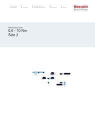
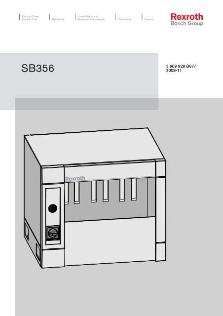
3 609 929 B67/2008-11 | <strong>SB</strong><strong>356</strong> <strong>Bosch</strong> Rexroth AG 27/1243 Delivery contentsThe delivery contents include:• 1 <strong>SB</strong><strong>356</strong> system box• 1 key• 1 suspension rail• 4 M8 DIN580 ring bolts• 1 <strong>SB</strong><strong>356</strong> system box operatinginstructions4 Product descriptionPerformance descriptionThe <strong>SB</strong><strong>356</strong> system box holds all the modulesin the tightening system. A board at the backof the <strong>SB</strong><strong>356</strong> connects all the insertedmodules and supplies them with thenecessary voltages.A maximum of 16 <strong>SB</strong><strong>356</strong> system boxes canbe connected to each other. NK350/NK350S and NKLxxx network couplers arerequired for this purpose. Further informationcan be found in the instruction manual for theNK350K350S network coupler(3 609 929 B69).The motor contactors integrated in the servoamplifiers are operated centrally by switchingthe emergency OFF via the VM350 powersupply module. Further information can befound in the instruction manual for theVM350 power supply module(3 609 929 B32).Device description765 4Fig. 1: View of <strong>SB</strong><strong>356</strong>Explanation of Fig. 1:1 Ring bolts (not assembled, included withthe system box)2 Safety warning (visible when the door isopen)3 Label area (visible when the door is open)4 Mains connection5 Ground connection6 Mains switch7 LockMains connectionComprehensive information on the mainsconnection can be found in chapter“6 Assembly” on page 29.1312ENGLISH ENGLISHSVENSKA PORTUGUÊS ESPAÑOL ITALIANO FRANÇAIS
28/124 <strong>Bosch</strong> Rexroth AG<strong>SB</strong><strong>356</strong> | 3 609 929 B67/2008-11Label areaA label area that can be used to identify theunit is provided on the system box (unitnumber in circuit diagram). The individualslots for the tightening channels are identifiedby a label (SE1/2, LT1, etc.).LT3 LT4 SE5/6 LT55 Transport and storageFor storing and transporting the product,always observe the ambient conditionsspecified in the technical data (see“Technical data” on page 41).When transporting <strong>SB</strong><strong>356</strong> system boxes,suitable transport safety devices must beused depending on the position of transport.Fig. 2: Label area within the <strong>SB</strong><strong>356</strong>Safety warningA safety warning is printed next to the labelarea. It warns against the high electricalvoltages in the system box during operationand provides maintenance information (see“Disassembly and replacement” on page 39).Ring boltsThey are used to fasten the system box whenmoving the box with a crane.LockThe lock is used to prevent the system boxdoor from being opened.Mains switchThe system box is switched on or off with themains switch.
3 609 929 B67/2008-11 | <strong>SB</strong><strong>356</strong> <strong>Bosch</strong> Rexroth AG 29/1246 AssemblyWhen installing the product, always observethe ambient conditions specified in thetechnical data (see “Technical data” onpage 41).Required tools• ScrewdriverThe system boxes can either be fastened towalls or racks using the mounting bracketson the rear or placed on their bases. Theinstallation position is horizontal. Systemboxes can be lined up side-by-side to formmulti-channel tightening systems. Systemboxes can only be lined up on top of eachother if a minimum distance of 300 mm isobserved.Assembling the <strong>SB</strong><strong>356</strong> system boxCAUTIONRisk of damage to personsand property!Assembly of the <strong>SB</strong><strong>356</strong> systembox requires basic mechanicaland electrical knowledge.y Only qualified personnel (see“Personnel qualifications” onpage 24) are authorized toassemble the <strong>SB</strong><strong>356</strong> systembox.y Measures to preventelectrostatic discharge (ESDprotection) must beundertaken to protect themodule and systemcomponents during allassembly work.y Observe the local, systemspecificregulations andrequirements; proper use oftools, lifting, and transportequipment; as well as therelevant standards, provisions,and accident preventionregulations.WARNING!Always keep the air ways for cooling clear.The lifting devices and fixtures for the systemboxes must be designed to correspond to theweights of the boxes (see “Technical data”on page 41).Four M8 DIN580 ring bolts are provided toassemble the <strong>SB</strong><strong>356</strong>.Assembly heightThe mains isolation device (mains switch)must be installed at a height of 0.6 m to1.9 m in accordance with EN60204-1. Theassembly height for the system boxes mustcorrespond to this requirement.WARNING!The system boxes must be bolted to thelift-out protection B (see followingassembly graphic) to prevent the systembox from being unintentionally lifted out ofthe suspension rail P .A suspension rail with the appropriate lengthis provided with the system box.WARNING!The system box may only be suspendedusing the suspension rail supplied!ENGLISH ENGLISHSVENSKA PORTUGUÊS ESPAÑOL ITALIANO FRANÇAIS
30/124 <strong>Bosch</strong> Rexroth AG<strong>SB</strong><strong>356</strong> | 3 609 929 B67/2008-11A10,8 8,2 6282050,5374ABB25 2510Fig. 3: Assembly graphic with suspension railPand lift-out protectionB
3 609 929 B67/2008-11 | <strong>SB</strong><strong>356</strong> <strong>Bosch</strong> Rexroth AG 31/124Inserting the modulesInsert the individual modules (SE352(M),KE350(G IL), LTU350/1, LT35x, NK350(S))in the <strong>SB</strong><strong>356</strong> as shown in Fig. 4.SE LT LTVM350*Tightening channel: SE352(M) tightening controller+LT35x/LTU350/1 servo amplifierTighteningchannel*Tighteningchannel*Tightening channel*or KE350(G IL)Fig. 4: <strong>SB</strong><strong>356</strong> slots for individual modulesNK350(S)Tighteningchannel*Tightening channel*Tightening channel*Slots 1-6 in the system box can be equippedwith a tightening channel (LT35x, LTU350/1,SE352(M)). The KE350(G IL) must beinserted in the KE slot (on the right of thesystem box). If several system boxes arenetworked via a NK350(S) network coupler,the KE350(G IL) must be inserted in thesystem box, which also contains the NK350Snetwork coupler.A maximum of one KE350(G IL) and 40tightening channels can be operated in onetightening system.The outer right slot is intended exclusively forthe NK350(S) network coupler.Slide the individual modules along the upperand lower guides.The modules should be completely insertedinto the <strong>SB</strong><strong>356</strong> and secured with the knurledbolts.For safety reasons and EMC regulations,close off unoccupied slots using dummypanels.Mains connectionThe power connections have been designedaccording to requirements for category 3overvoltage.CAUTIONRisk of damage to personsand property!The system box may only beoperated in grounded networks.Operation in networks that havenot been directly grounded (ITnetworks) is not permitted, as airpaths and creepage distances inthe module may be overloaded.ENGLISH ENGLISHSVENSKA PORTUGUÊS ESPAÑOL ITALIANO FRANÇAIS
32/124 <strong>Bosch</strong> Rexroth AG<strong>SB</strong><strong>356</strong> | 3 609 929 B67/2008-11CAUTIONRisk of damage to personsand property!Solely permissible protectivemeasure in accordance withEN 50 178: protective grounding.Each supply cable on the systembox must have a PE wire. Inaddition, a PE wire with a minimumcross-section of 10 mm 2 Cu mustbe connected at the X1N3.1/X1N3.2 interface underneath thesystem box (Fig. 5).Fig. 5: X1N3.1/X1N3.2 PE wire connectioniX1N3.1X1N3.2NOTE!If several system boxes are connectedtogether, the PE wire can be looped fromone system box to another.CAUTIONRisk of damage to personsand property!Dangerous shock currents due toinsufficient PE wire connections!The PE wire connections may notbe adversely affected bymechanical, chemical orelectrochemical influences. Theconnection must be permanent.CAUTIONRisk of damage to personsand property!To ensure potential equalizationfor all system components, thesystem boxes, as well as thetightening spindles' carrying plateand the workpiece, must beadequately grounded.CAUTIONRisk of damage to personsand property!Residual currents from theintermediate circuit and the mainsfilter could disable residualcurrent-operatedprotecteddevices (RCDs). For this reason,the system box may not beoperated on RCDs!
3 609 929 B67/2008-11 | <strong>SB</strong><strong>356</strong> <strong>Bosch</strong> Rexroth AG 33/124The mains connection is via the screwterminals on the mains switch (Fig. 6).The cable fitting (Ø 8 mm - 13 mm) islocated in the system box base (Fig. 5). The<strong>SB</strong><strong>356</strong> mains connection must be 3-phase(≥ 4 x 2.5 mm 2 ) and include a PE wire.To avoid short circuits and ground faults, a3-phase fuse must be provided.1L1 3L2 5L3PEiNOTE!The user is responsible for selectingsuitable mains connection cables.Voltage selectionThe voltage selection terminals in the <strong>SB</strong><strong>356</strong>make it possible to operate the system box ina voltage range of 380 V to 500 V. Thesystem box is set to 400 V on delivery(Fig. 7).ENGLISHENGLISHFig. 6: Mains connection terminalsTable 1:Mains connection terminalsSignalDescription/functionVoltage/currentSVENSKA PORTUGUÊS ESPAÑOL ITALIANO FRANÇAISPE PE wire PE potential1L1 L1 mains connection3L2 L2 mains connection380-500 V~4.6-3.5 A5L3 L3 mains connection
3 609 929 B67/2008-11 | <strong>SB</strong><strong>356</strong> <strong>Bosch</strong> Rexroth AG 35/124Power switchSettingmarkFig. 8: Power switch5 A maxOn the <strong>SB</strong><strong>356</strong>, the trigger behavior of the Q0power switch must be assigned as follows:Table 3:Trigger behavior of power switchVoltagePower setting on Q0380 V5.0 A400 VGroup 1(G1)4.8 A420 V 4.5 A440 V4.3 A460 VGroup 2(G2)4.1 A480 V 4.0 A500 VGroup 3(G3)3.8 AMains connected loads(nominal values)The required connected load of the <strong>SB</strong><strong>356</strong>system box depends on the number and sizeof the tightening channels to be operated. As,however, an <strong>SB</strong><strong>356</strong> must always beconsidered as fully equipped, werecommend configuring the connected loadfor a fully equipped <strong>SB</strong><strong>356</strong> system box (seechapter “15 Technical data”).If the <strong>SB</strong><strong>356</strong> system box is not fully equippedand fused and it is certain that they will not beretrofitted with additional tighteningchannels, the mains connected load can beconfigured in accordance with Table 4.Tab. 4:3-phase connectionLT353withEC302LT353withEC303LT354withEC304LT355withEC305Number of LT35x in <strong>SB</strong><strong>356</strong>1* 2 3 4 5 6500VA600VA700VA1200VA700VA950VA1200VA1800VA900VA1250VA1700VA2500VA1050VA1500VA2100VA1200VA1750VA2500VA1350VA2000VA–– – –ENGLISH ENGLISHSVENSKA PORTUGUÊS ESPAÑOL ITALIANO FRANÇAIS
3 609 929 B67/2008-11 | <strong>SB</strong><strong>356</strong> <strong>Bosch</strong> Rexroth AG 37/1247 CommissioningCAUTIONRisk of damage to personsand property!Commissioning of the <strong>SB</strong><strong>356</strong>system box requires basicmechanical and electricalknowledge.y Only qualified personnel (see“Personnel qualifications” onpage 24) are authorized tocommission the system.CAUTIONDanger to life due toinsufficient emergency OFFequipment!Emergency OFF equipment mustbe functioning and within reach inall system modes. Release of theemergency OFF equipment maynot result in an uncontrolledsystem restart!y Always check the emergencyOFF chain before switching onthe system!y Further information on theemergency OFF can be foundin the instruction manual forthe VM350 power supplymodule (3 609 929 B32).1. Connect the PE wire.2. Open the <strong>SB</strong><strong>356</strong> if it is locked.3. Remove both covers (A) and (B) byloosening the six screws:ABCAUTIONOverheating of the <strong>SB</strong><strong>356</strong> systembox and its components!Damage to the system box and itscomponents from overheatingy Always keep the air ways forcooling the <strong>SB</strong><strong>356</strong> system boxclear.Fig. 9: Removing the cover4. Select the voltage (factory setting:400 V).5. Set the Q0 power switch to theappropriate position (see Table 3).ENGLISH ENGLISHSVENSKA PORTUGUÊS ESPAÑOL ITALIANO FRANÇAIS
38/124 <strong>Bosch</strong> Rexroth AG<strong>SB</strong><strong>356</strong> | 3 609 929 B67/2008-116. Close the covers which were previouslyopened.7. Connect to the mains.8. Insert the NK350/ NK350S network coupler(if used).9. Insert the modules.10. Close any unoccupied slots with an appropriatedummy panel (see Table 6).11. Lay all the connection cables through thecable duct strip.12. Check that all the connection lines andmodules are properly connected.13. Switch the <strong>SB</strong><strong>356</strong> on at the powerswitch.14. Check that the emergency OFF circuit isfunctioning correctly before commissioningthe tightening system.15. Configure, program and parameterize thetightening sequences with the BS350operating system.8 OperationCAUTIONAny dirt or liquids penetratingthe device lead tomalfunctions!Failure to adhere to this may lead topersonal injury or and damage toequipment caused bycontamination. The interior of thesystem boxes have been designedin compliance with degree ofpollution 2 (equivalent to HD 625.1and EN 50178).y Ensure that the doors arealways closed when operatingthe <strong>SB</strong><strong>356</strong> system box.Operation is not necessary while the system isrunning.Table 6: Dummy panelsTypeDummy panelforOrder numberBP351 Servo amplifier 3 608 878 058BP352 Controller and 3 608 878 060servo amplifier
3 609 929 B67/2008-11 | <strong>SB</strong><strong>356</strong> <strong>Bosch</strong> Rexroth AG 39/1249 Maintenance andrepair11 Disassembly andreplacementCleaning and careMaintenanceCAUTIONAny dirt or liquids penetratingthe device lead tomalfunctions!Safe function of the <strong>SB</strong><strong>356</strong>system box is no longer ensured.y Always ensure absolutecleanliness when working onthe <strong>SB</strong><strong>356</strong> system box.The <strong>SB</strong><strong>356</strong> system box is maintenance-free ifused as intended.Spare partsPlease refer to the address directory underwww.boschrexroth.com and in chapter“16 Service and sales” on page 42 for theadresses of our foreign subsidiaries.10 DecommissioningFor details on how to disassemble or replacethe <strong>SB</strong><strong>356</strong> system box, please refer tochapter “11 Disassembly and replacement”on page 39.Required tools• ScrewdriverDisassemblingFollow the warnings imprinted on the<strong>SB</strong><strong>356</strong>:WARNINGDangerous internal voltage!y Before opening the device orperforming maintenance work,make sure that the device isnot under voltage, protect itagainst being switched onagain, and allow for a10 second discharging time.y Read the manual before usingthe system or performingmaintenance work.Fig. 10: Imprint on the <strong>SB</strong><strong>356</strong>ENGLISH ENGLISHSVENSKA PORTUGUÊS ESPAÑOL ITALIANO FRANÇAIS
40/124 <strong>Bosch</strong> Rexroth AG<strong>SB</strong><strong>356</strong> | 3 609 929 B67/2008-11CAUTIONDamage to the <strong>SB</strong><strong>356</strong> systembox or tightening system ifplug-in connections areconnected or disconnectedwhile under voltage!y First switch off the system atthe power switch and then atthe mains or pre-fuse. Allow fora minimum discharging time of10 seconds.Proceed as follows to disassemble the<strong>SB</strong><strong>356</strong> system box:1. First switch off the system at the powerswitch and then at the mains or pre-fuse.Allow for a minimum discharging time of10 seconds.2. Loosen the main power lines from thesystem box.3. Loosen the knurled bolts on the front forall components and remove them.4. Mount dummy panels, if necessary.CAUTIONRisk of damage to personsand property!y First switch off the system atthe power switch and then atthe mains or pre-fuse beforeworking on the terminals. Allowfor a minimum discharging timeof 10 seconds.y Check that the terminals arenot under voltage.CAUTIONRisk of damage to personsand property!y Once the device has beenswitched off, it cannot beswitched back on again until atleast 30 seconds haveelapsed.12 DisposalEnvironmental protectionCareless disposal of the <strong>SB</strong><strong>356</strong> system boxcould lead to pollution of the environment.Therefore, dispose of the device inaccordance with the currently applicableregulations in your country. You can alsosend the device to <strong>Bosch</strong> Rexroth fordisposal.13 Extension andconversionDo not convert the <strong>SB</strong><strong>356</strong> system box.14 TroubleshootingMalfunctions and information on errors aredisplayed in the tightening system via theBS350.If you are not able to remedy an occurringdefect, please contact one of the addressesthat you can find underwww. boschrexroth.com or in the addressdirectory in chapter “16 Service and sales”on page 42.
3 609 929 B67/2008-11 | <strong>SB</strong><strong>356</strong> <strong>Bosch</strong> Rexroth AG 41/12415 Technical dataTable 7:Designation<strong>SB</strong><strong>356</strong>Order number 0 608 830 251Input voltagePeak powerNominal powerProtection classaAdjustableSubject to alterations.3 x 400 V ± 10%, 50 - 60 Hz (380 V to 500 V) a10000 VA2500 VAProtection class IMax. permissible altitude for use2000 amsl (an isolating transformer isrecommended at altitudes above 2000 amsl).Due to low air pressure, a reduction in nominalOperation at altitudes over 1000 m amslpower of approx. 1% per 100 m altitude can beexpected at heights above 1000 m amsl.Permissible ambient temperature 45 °CPermissible relative humidity during operation 20 % to 90 %, non-condensingPermissible storage temperature –20 °C to 70 °CPermissible relative storage humidity 20 % to 95 %Protection type IP 54Dimensions with base (W x H x D)600 mm x 510 mm x 470 mmWeight (empty/fully equipped)55 kg/75 kgENGLISH ENGLISHSVENSKA PORTUGUÊS ESPAÑOL ITALIANO FRANÇAIS