series 1530 horizontal pumps - Pristine Water Solutions Inc
series 1530 horizontal pumps - Pristine Water Solutions Inc
series 1530 horizontal pumps - Pristine Water Solutions Inc

Create successful ePaper yourself
Turn your PDF publications into a flip-book with our unique Google optimized e-Paper software.
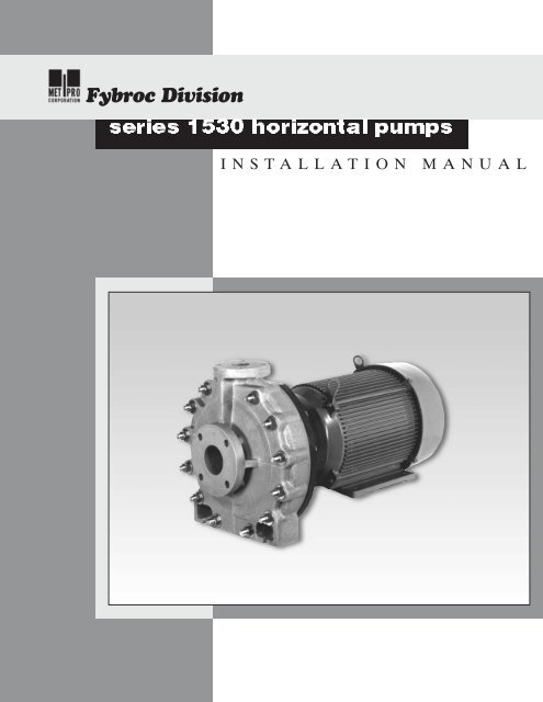
Fybroc Division<strong>series</strong> <strong>1530</strong> <strong>horizontal</strong> <strong>pumps</strong>INSTALLATION MANUAL
INDEXPagePageFybroc Warranty 3 Assembly 10Installation Instructions 4 John Crane Type 8B2 10Location 4 John Crane Type 8-1T 11Foundation 4 John Crane Type 8-D 12Piping the Pump 4 Impeller Adjustment 13Suction Piping 5 Operational Start-up Checklist 14Discharge Piping 5 Sectional Drawings 15Ancillary Piping 5 <strong>1530</strong> Group I 15Electrical Connections 6 <strong>1530</strong> Group II 16Start-up and Operating Procedures 7 Typical Mechanical Seal Installations 17Lubrication 7 Product Flush 17Seal Flushing 7 External Flush 18Mechanical Seals 7 Mechanical Seal Piping/Flow Requirements 19Priming 7 Single Mechanical Seal 19Starting 7 Double Mechanical Seal 20Operational Check List 7 Notes 21Maintenance 7Motor 7Trouble Check List 8Assembly/Disassembly Procedures 9General 9Disassembly 9ORDERING REPLACEMENT PARTSFor future reference fill in the following information from the pump nameplate.This will be necessary to ensure accuracy when ordering replacement parts.ModelSizeSerial NumberImpeller Diameter InstalledSeal TypeMaterial of Construction
Fybroc DivisionWARRANTYPERFORMANCEGUARANTEEACCEPTANCETESTSPERFORMANCEPRESENTATIONSFIELD TESTINGALL WARRANTIESFYBROC <strong>pumps</strong> are warranted by the Company, insofar as the same are of its own manufacture,against defects in materials and workmanship under proper and normal use andservice, for a period of one year from the date of original shipment from the factory.FYBROC's obligation is limited, however, to furnishing without charge, F.O.B. its factory,new parts to replace any similar parts of its own manufacture so proving defective withinsaid period, provided the Buyer has given FYBROC immediate written notice upon discoveryof such defect. No allowance will be made for labor charges. FYBROC shall have theoption of requiring the return of the defective material, transportation prepaid, to establishthe claim.FYBROC makes no warranty or guarantee whatsoever, either express or implied, of primemover, starting equipment, electrical apparatus, parts or material not manufactured byFybroc, except to the extent that warranty is made by the manufacturer of such equipmentand material.FYBROC assumes no liability for damages or delays caused by defective material, and noallowance will be made for local repair bills or expenses without the prior written approvalor authority of FYBROC.Under no circumstances will FYBROC be liable for indirect, special or consequential loss ordamage of any kind and the Buyer assumes all liability for the consequences of its use ormisuse by the by the Buyer, his employees, or others.Is at the specified point of rating only and will not cover performance under conditions varyingtherefrom, nor for sustained performance over any period of time.If required, shall be conducted in accordance with the practices as set forth in the HydraulicInstitute Standards. The expense of any such tests shall be borne by the buyer.Are based on shop laboratory tests with cold water as outlined in the Hydraulic InstituteStandards.Due to the inaccuracies of field testing, the results of any such tests conducted by or forthe Buyer shall be interpreted as being only indicative of the actual field performance of thepump. No equipment will be furnished on the basis of acceptance by results of field tests.If the buyer, after such a test, questions the performance of the pump, he may at his optionrequest a test to establish the performance. Such tests will be conducted in accordancewith the above paragraph entitled “Acceptance Tests.”Are void if -a. Pipe strains are the cause of damage.b. Pump handles liquids other than those specified in detail.c. NPSH lower than required by pump impeller.d. Operating speed is higher than specified.e. Improper field installation.To combat corrosion, abrasion, erosion, or pumping solids, foreign objects, or pumpingliquids at elevated temperature, any such recommendations will be based on the bestavailable experience of FYBROC and the supplier of the material and industry, BUT WILLNOT CONSTITUTE A GUARANTEE AGAINST THESE EFFECTS.RECOMMENDATIONSFOR SPECIALMATERIALSThe foregoing warranty is made in lieu of all other warranties guarantees, obligations orliabilities, expressed or implied, by FYBROC or its representatives. All statutory or impliedwarranties, other than of title, are hereby expressly negated and excluded.All illustrations and provisions in specifications are descriptive and are not intended aswarranties. Penalty of any kind are not acceptable unless approved in writing by an officerof Met-Pro Corporation.3
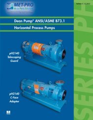
INSTALLATION HORIZONTAL PUMPSLOCATIONThe pump should ideally be placed as close aspossible to the liquid supply source. Allow sufficientspace on the sides and overhead to permitinspection and maintenance work to be performed.FOUNDATIONThe foundation for the pump should be level,provide rigid support of pump and motor. It shouldalso be of sufficient mass to dampen any vibrationsdeveloped. Typically this is accomplishedby installing and grouting a Fybroc baseplate ona concrete foundation.Foundation bolts of the proper size should beimbedded in the concrete with anti-rotation lugs,located by a drawing or template (See Table 1below for bolt-size and locations). A pipe sleevelarger than the bolt should be used to allow enoughlateral movement for final positioning of the bolts(See Figure 1 below). Leveling wedges orshims should be placed under the sides of thebaseplate to level the unit and the foundationbolts slightly tightened.FIGURE 1TABLE 1Base A B C D E F BoltPlateSize1T-22" 22 19 1/2 8 8 2 5/8 3/4 1/21T-24" 24 21 1/2 9 8 2 5/8 3/4 1/22T-30" 30 27 1/2 9 9 2 7/8 3/4 1/23-21" 21 18 1/2 12 7 1/2 3 3/4 3/4 1/23-22" 22 19 1/2 15 7 1/2 4 1 3/43-27" 27 24 1/2 15 7 1/2 4 1 3/43-29" 29 26 1/2 19 7 1/2 4 1 3/43-32" 32 29 1/2 19 7 1/2 4 1 3/4A wood form can now be built around the edge ofthe baseplate to contain the grout. The top of therough concrete foundation should be wetted downprior to grouting. A good grade of non-shrinkinggrout can now be packed through the open end ofthe fiberglass baseplate. Once the grout has fullyhardened, usually about 48 hours after pouring,the foundation bolts can be fully tightened.FIGURE 2PIPING THE PUMPAll flanged connections to the pump should be fullflat face with full contact gaskets. Raised faceflanges or partial contact gaskets should not beused as excessive strains can be applied to thepump flanges upon tightening.The pump has been designed with all necessarystrength factors for long, reliable service life.However, due to the composite construction, caremust be taken during installation to avoid unnecessarypipe strain. If severe piping strains are to beencountered, flexible connections are recommendedin the suction and discharge pipe lines. Whenlined piping is used, flange alignment should becarefully checked. Spacer ring gaskets arerecommended to assure parallel alignment of pipeand pump flanges. The following flange bolt torquevalues should be used:Flange SizeBolt Torque1" 9-12 ft-lbs.1 1/2" 9-12 ft-lbs.2" 18-24 ft-lbs.3" 23-30 ft-lbs.4" 27-36 ft-lbs.6" 35-50 ft-lbs.4
All piping must be supported independently of thepump. The piping should always line up naturallywith the pump flanges. Never draw the piping tothe suction or discharge flanges of the pump.Outside installations should be properly compensatedfor changes in ambient temperatures. Referto pipe manufacturers standards for properinstallation. Omission of this could result in severestrain transmitted to the pump flanges.The piping should be as short and direct as possible.Avoid all unnecessary elbows, bends and fittings,as they increase friction losses in the piping.SUCTION PIPINGA) To minimize friction loss, the length of the suctionpipe (from process to pump inlet) should be asshort as possible. It is important that NPSHavailable to the pump is greater than theNPSH required by the pump, long suction runsgreatly affect NPSH and should be consideredcarefully. See pump performance curve forNPSH requirements.B) The diameter of the suction pipe should be aslarge as the pump suction. If long suction runsare encountered, the suction pipe diametershould be increased to reduce the NPSHrequired.C) <strong>Inc</strong>reasers or reducers, if used, should beeccentric and installed with the eccentric sideon the bottom of the pipe to prevent air traps.D) Elbows, fittings, valves or expansion jointsshould be avoided at the suction flange. Allowa straight run of at least 10 pipe diameters intothe suction of the pump.E) If a valve is to be installed in the suctionpiping, only full flow valves offering a minimumflow disturbance should be used (ball, plugtypes). These valves should be for shut-offonly when the pump is not running, and not forthrottling or controlling flow. Centrifugal <strong>pumps</strong>should never be throttled on the suction side.F) Provisions for a suction pressure gauge shouldbe included.DISCHARGE PIPINGA) Installation of a valve in the discharge line thatcan be used as a block for inspection andmaintenance is recommended. It should be ofa design to allow throttling or flow control.B) The diameter of the discharge pipe should beas large or larger than the pump discharge.C) Provision for a discharge pressure gaugeshould be included.ANCILLARY PIPINGA) The diameter of the ancillary or seal pipingshould be large enough to meet the seal flushingrequirements. Typically this is 1/4-1/2 GPMat a pressure of 15-25 PSI above the suctionpressure for most mechanical seals. Refer topages 25 and 26 for recommended seal flushflow rates and piping installations.B) Where the ancillary piping is connected to thepump only plastic fittings shall be used.WARNING: FAILURE TO USE PLASTICFITTINGS MAY RESULT IN DAMAGE TOTHE PUMP.C) Many modern flush systems incorporate electricallyactuated solenoid valves to conserveand control the flow of flush liquids, ensure thatthe flush liquid is flowing to the seal before thepump is started.D) On double seal arrangements with flush in andflush out connections, flow control valvesshould be installed in the flush out or downstreamside.The pump shaft should turn freely by hand afterthe piping has been connected to the pump. Thisis to insure that the piping has not caused bindingin the pump. If binding occurs, check for causeand correct.5
ELECTRICAL CONNECTIONSA) All electrical work done to the unit should bedone by a qualified electrician. All local, state andfederal electrical codes should be adhered to.B) Wire motor according to motor manufacturersinstructions. Ensure that all connections andcovers are tight and that proper sized wire andswitch-gear are used.C) All <strong>pumps</strong> operate in a clockwise directionwhen viewed from the motor end, (seedirection arrow on the pump motor adapter).Connect electric motor to power supply and jogmotor to check rotation. If motor is operatingin wrong direction, reverse leads and recheck.WARNING: DO NOT START PUMP WITHLIQUID IN THE CASING UNTIL MOTORROTATION HAS BEEN DETERMINED ASDAMAGE COULD RESULT FROMSUSTAINED REVERSE ROTATION UNDERPUMPING LOAD.6
LUBRICATIONOn a close coupled pump only the motor requireslubrication. Since all motors come from the factorypre-lubricated there is no action required.SEAL FLUSHINGMechanical SealsDo not operate the <strong>pumps</strong> without liquid to themechanical seal. Depending on the flush arrangementof the pump, the fluid to the seal may bepiped from the pump discharge externally orinternally, or from an external clean source. If thepump is fitted with an internal or bypass flusharrangement, then the pump must be floodedwith liquid prior to starting to ensure that themechanical seal is lubricated. If the pump isequipped for an external flush system, then flushliquid must be supplied to the seal prior to starting.Proper flow for external flushing will vary from 1/4to 1/2 GPM at a pressure of 15 to 25 PSI abovethe stuffing box pressure.PRIMINGSuction valve must be fully open. The pump casingand suction pipe must always be full of liquidbefore the pump is started. Centerline dischargedesigns are self-venting therefore the dischargevalve should be opened to release any air trappedin the pump and then left slightly open at start-up.STARTINGPrior to starting, turn pump shaft by hand to besure rotating elements are free. If it rubs or binds:A Check for piping strains on casing flanges,or other loads on casing.B) Check impeller clearance.(See impeller adjustment).Prior to starting pump recheck installation procedureswith the operational start-up checklist foundon page 14 of this manual.Start pump and bring up to speed, open dischargevalve to the rated flow.WARNING: DO NOT RUN PUMP WITH ACLOSED DISCHARGE VALVE AS THE LIQUIDIN THE PUMP WILL RAPIDLY INCREASE INTEMPERATURE, POSSIBLY CAUSINGDAMAGE TO PUMP.START-UP AND OPERATING PROCEDURESCheck flush water to mechanical seal, if not lubricatedfrom the pump discharge.OPERATIONAL CHECK LISTA) Periodically check mechanical seals for properoperation.B) Periodically check lubrication to the motorbearings.C) Periodically check for excessive vibrations.Correct if necessary.MAINTENANCEFybroc <strong>pumps</strong> are designed for a long servicelife. The only scheduled maintenance items arethe lubrication intervals for the motor. Pleaserefer to the lubrication procedures given below.MOTORThe motor relubrication intervals are greatly influencedby the environment it is in and the length oftime it runs. Refer to the following chart for typicalrelubrication values for motors. Standard duty iswhen the motor is operated eight hours a day andthe environment is free from dust. Severe duty iswhen the motor runs twenty-four hours per daywith exposure to dirt and dust.Sync RPM Motor Frame Type of ServiceRange Range Standard Duty Severe Duty143JM - 256JM 5 Yrs 3 Yrs3600 284JM - 286JM 1 Yr 4 Mos324JM - 365JM 9 Mos 3 Mos143JM - 256JM 7 Yrs 3 Yrs1800 284JM - 326JM 4 Yrs 1.5 Yrs364JM - 365JM 2.5 Yrs 10 Mos143JM - 256JM 7 Yrs 3 Yrs1200 284JM - 326JM 4 Yrs 1.5 Yrs364JM - 447JM 3 Yrs 1 YrInstructions For Lubricating MotorsBefore greasing, be sure fittings are clean and freefrom dirt. Remove grease relief plug or plate andusing a low pressure grease gun pump in therequired grease. Do not over-grease. After relubricatingallow motor to run for an hour beforereplacing relief hardware.7
TROUBLE CHECK LISTRefer to the following diagnostic section ifhydraulic problems are encountered in thepump operation.PROBLEM:Not enough liquid, or no liquiddelivered.PROBLEM:Air pocket in suction line.Insufficient NPSH.Air or gases in liquid.Pump takes to much power.CHECK:Suction pipe and /or pumpcasing not filled with liquid.Speed too low.(Result, reduced TDH).Suction lift too high or insufficientNPSHA. (Cavitation).CHECK:Speed too high.Head lower than rating; pumpingbeyond design point.Liquid heavier than specified;check viscosity and specificgravity.Impeller or suction pipe pluggedwith solids.Wrong rotation.(Result, reduced TDH).Mechanical defects (Bent shaft,rotating element binds, packingtoo tight, misalignment).Air pockets in suction line or airleaking in through packingbox area.Suction strainer plugged, if usedin suction line.PROBLEM:Not enough pressure.CHECK:Speed too low.Air or gases in the liquid.Check impeller diameter.Mechanical defects (impellerclearance too great; impellerdamaged).Wrong rotation.Pressure gauge in a poor location.PROBLEM:Pump runs but intermittently<strong>pumps</strong> liquid.CHECK:Suction line leaks.Stuffing box leakage of air.8
ASSEMBLY/ DISASSEMBLY PROCEDURES FOR HORIZONTAL PUMPSGENERALThe Fybroc pump is designed for easy inspectionand service because of its back pullout construction.For inspection or replacement of certainparts, the work can be done in place, without thenecessity to remove the complete pump to amaintenance area. Refer to applicable SectionalDrawing in this manual for item numbersmentioned below.Before any work is done the following proceduresand precautions should be taken:1) The electric motor should be either disconnectedfrom its power source, or the switch or circuitbreaker must be secured in an “off” position sothat the motor cannot be accidentally started.2) Depending upon the fluid being pumped, theproper protective equipment should be worn(gloves, mask, respirator, goggles or safetyglasses, etc.) to prevent contact with the fluidin the pump or pipelines.3) Check the valves on the suction and dischargelines to be sure they are closed and secured.4) If the mechanical seal is flushed from an externalsource, turn off the valve in the supply lineand disconnect the flush line.5) The liquid trapped in the pump and piping shouldbe drained. Care should be taken to either trapthe fluid in a container or to divert it to a properdisposal area so that the area around the pumpand base will not be contaminated.DISASSEMBLY1) If the complete pump is to be removed to amaintenance area, remove the bolts holdingthe motor and casing to the baseplate. Removethe bolts on the suction and discharge flangeconnections. Now the whole pump can beremoved. If the casing is to be left in placeremove the screws holding the motor to thebaseplate and then remove the casing bolts,nuts, washers and shims securing the casingto the cover and motor adapter (Items 1C,1D, 1E, 67). Now the rotating assembly canbe pulled away from the casing and removed.Note the number of shims removed. Twojackscrews (Item 19D) are provided toease disassembly.2) If the casing was removed with the pump,remove the casing bolts, nuts, washers andshims securing the casing to the cover andframe adapter (Items 1C, 1D, 1E, 67). Therotating assembly can be pulled away fromcasing. Note the number of shims that wereremoved. Two jackscrews (Item 19D) areprovided to ease disassembly. Now the pumpcan be placed in a convenient location todisassemble it.3) Remove the cover o-ring (Item 73) and place ina container with the casing hardware.4) To disassemble the impeller assembly, removethe locking ring (Item 14 B) by removing thetwo Allen head screws, thus exposing thesegment key (Item 14A), which can now beremoved from the impeller sleeve.5) If the pump is provided with a mechanical sealutilizing set screws to drive the seal, loosen theset screws. If the mechanical seal is of thepreset outside type, reinstall the seal settingclips, prior to loosening the set screws.6) Remove rear fan cover from motor; use visegrips or pipe wrench to hold rear motor shaftextension from turning. Remove fan if required.Do not attempt to hold fan. The impellerassembly can now be removed by turning theimpeller in a counter-clockwise direction facingthe impeller. A strap wrench or similar devicemay be required to disengage the screwthreads. The impeller, stuffing box cover, andseal can now be removed as a unit.7) If the mechanical seal is a single outside sealbe sure the set screws are loose and pull therotary seal assembly off the sleeve, using atwisting motion as it is removed. The impeller(Item 2) can be removed from the cover.Remove the four bolts and washers (Item 17C,17E) securing the gland (Item 17) to the cover(Item 11) and remove the gland and then theseal stationary from the cover. The carbon andceramic elements of the seal should be handledcarefully to prevent chipping or scratching.9
If the mechanical seal is a double inside seal,remove the four bolts and washers (Item 17C,17E) securing the gland (Item 17) to the cover(Item 11) and remove the gland. Be sure theset screws are loose, and pull the rotary sealassembly off, using a twisting motion as it isremoved. The impeller (Item 2) can beremoved from the cover. Next remove thestationary seal faces from the gland andcover by gently pressing them out using yourthumbs. The carbon and ceramic elementsof the seal should be handled carefully toprevent chipping or scratching.8) The motor shaft adapter (Item 6) may beremoved from the motor shaft by removing theAllen head screw (Item 6A). The drive key(Item 46) will slide off with the shaft adapter.In the bore of the shaft adapter there may besome shims to take up the motor manufacturer’sshaft length tolerances. Be sure to notethe number and thickness of the shims used.9) Remove pump adapter (Item 71) and motoradapter (Item 71B) if provided.ASSEMBLY1) Inspect casing, cover and impeller for anydamage and make sure all sealing surfacesare free of dirt and scratches. If pump isequipped with an internal seal flush, makesure cover flush hole is clear. Check motorend float. Excessive shaft end float (greaterthan .015") can result in damage to pumpand or mechanical seal.2) If equipped install the motor adapter (Item 71B).Ensure that the adapter is seated squarely onthe motor before tightening adapter screws,this may require some sanding of the paint onthe pilot diameters. Secure with adapterscrews (Item 71C), torque to 25 ft-lbs.3) Install the pump adapter (Item 71). Ensurethat the adapter is seated squarely on themotor adapter or motor before tighteningadapter screws, this may require some sandingof the paint on the pilot diameters. Securewith adapter screws (Item 71A), torque to25 ft-lbs. end of shaft.4) Place one .062" shim washer (Item 6B) in theshaft (Item 6) bore. Install key (Item 46) intothe shaft key-way slot from the inside of theshaft bore. Slide assembly onto motor shaftand temporarily secure with shaft screw(Item 6A).5) Place six impeller adjusting shims (Item 67,three on each side) and the cover (Item 11) onto the pump adapter. Ensure that the cover isseated squarely on the pump adapter, this mayrequire some sanding of the paint on the pilotdiameter. Clamp the cover tightly to theadapter with clamps or bolts.6) Thread the impeller (Item 2) onto the shaftadapter until it bottoms on the shoulder ofthe shaft adapter. Place a feeler gaugebetween the cover and the balance vaneson the impeller.7) The gauge should read approximately .035", ifit does not, repeat steps 4-6 using a differentwasher or combination of washers until theproper clearance is obtained. Four washersare supplied by Fybroc: 2@.010", 1@.032"and 1@.062" this will provide for 0-.110" worthof shimming capabilities which will adapt to anymotor used.8) Once the proper number of shims is determined,remove the impeller, cover and plasticshims and tighten the shaft adapter screw to35 ft-lbs. for 3/8" screws and 50 ft-lbs. for1/2" screws.9) Place some anti-seize lubricant on the shaftadapter impeller threads.10) The Fybroc pump, as standard, is equipped witha single outside seal with stationary seal faceand rotating compression unit, or a doubleinside seal with stationary seal faces and rotatingdouble seal compression unit. The followinginstallation instructions are based on these sealtypes. When other types of seals are used,please refer to the manufacturer's installationdata. Determine the type of seal being used andrefer to the following sections.SINGLE OUTSIDE SEAL INSTALLATIONJOHN CRANE TYPE 8B21) Remove the mechanical seal from its packaging,inspect for any damage, and keep sealfaces clean and free from contaminantsduring installation. DO NOT GREASE ORLUBRICATE SEAL FACES.10
2) Install the inboard stationary gasket and thestationary seal insert into their bores on thepump cover. Then place the outboard stationarygasket over the stationary insert. Next placethe seal gland over the stationary insert andgaskets, making sure that all the gaskets havebeen installed properly before securing thegland bolts. Be sure that the gland pilot isproperly engaged, and draw up the gland boltsevenly, cross staggering adjustment of thebolts. Proper gland bolt adjustment is especiallyimportant where clamp style inserts are used.The gland bolts should be torqued to amaximum of 10 ft/lbs.3) Lightly coat the impeller sleeve with a suitablelubricant. Carefully slide impeller sleevethrough the cover, being careful not to chipthe stationary sealing face.4) Lubricate the rotary unit o-ring with a suitablelubricant. Then engage the rotary assemblyover the impeller sleeve. Use a slight twistingmotion as the rotary unit is slid down theimpeller sleeve until it touches the stationarysealing face. Do not tighten set screws orremove setting clips.5) Mount the impeller, cover and seal assemblyonto the pump adapter, making sure theimpeller threads are firmly bottomed on theshaft threads. Install the cover shims (Item 67)between the pump adapter and cover.6) Install the segment key (Item 14A) in the correspondingslot at the rear of the impeller sleeve.Make sure the teeth are properly engaged andinstall locking ring (Item 14B).7) Install cover o-ring (Item 73), casing (Item 1)and secure with the casing bolts, nuts andwashers (Items 1C, 1D, 1E). Make sure theo-ring is in place and that the impeller isnot contacting the casing and tighten thecasing bolts.8) Rotate the motor shaft manually while pushingon the motor shaft to take up any shaft endfloat. Confirm no binding exists. Ensure thatthe seal faces are still contacting by slidingthe seal rotary unit until it touches thestationary unit with a slight twisting motion.Tighten the rotary unit set screws and removethe setting clips.9) Replace fan and/or fan cover on motor andmake appropriate piping connections to theseal assembly.DOUBLE SEAL INSTALLATIONJOHN CRANE TYPE 8-1T1) Remove the mechanical seal from itspackaging, inspect for any damage, keepseal faces clean and free from contaminantsduring installation. DO NOT GREASE ORLUBRICATE SEAL FACES.2) Lightly lubricate the inboard stationary inserto-ring and cover bore with a suitable lubricantand then install the inboard stationary into thepump cover bore.3) Lightly lubricate the outboard stationary inserto-ring and gland bore and then install the outboardstationary into the gland bore.4) Lightly coat the impeller sleeve with a suitablelubricant. Carefully slide impeller sleevethrough the cover, being careful not to chip thestationary sealing face.5) Lubricate the rotary unit o-rings with a suitablelubricant. Then engage the rotary assemblyover the impeller sleeve. Use a slight twistingmotion as the rotary unit is slid down theimpeller sleeve until it touches the stationarysealing face. Do not tighten set screws.6) Install the gland o-ring into its groove on thegland. Then place the gland over the rotatingseal assembly, making sure the gland o-ring isin place before securing the gland bolts. Besure that the gland pilot is properly engaged,and draw up the gland bolts evenly, cross staggeringadjustment of the bolts. The gland boltsshould be torqued to a maximum of 10 ft/lbs.7) Mount the impeller, cover and seal assemblyonto the pump adapter, making sure theimpeller threads are firmly bottomed on theshaft threads. Install the cover shims (Item 67)between the pump adapter and cover.8) Install the segment key (Item 14A) in thecorresponding slot at the rear of the impellersleeve. Make sure the teeth are properlyengaged and install locking ring (Item 14B).11
OPERATIONAL START-UP CHECKLISTFoundation level and baseplate grouted.Foundation bolts tight.Motor and pump mounting bolts tight.Suction and discharge connections secure.Flush piping installed if required.Electrical connections secure and covered.Turn motor shaft by hand, ensure that it does not bind.Jog motor/Check rotation.Ensure seal is properly flushed.Suction valve is open, Discharge valve is slightly open.Ensure that pump is primed.Start pump and open discharge valve to desired flow rate.Check flush water flow and pressure.Check for excessive vibration.Check mechanical seal for no leaks after run-in.14
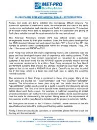
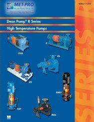
15<strong>1530</strong> SERIES GROUP 1
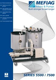
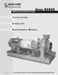
<strong>1530</strong> SERIES GROUP 216
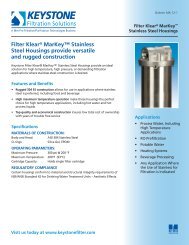
<strong>1530</strong> SERIES SEAL AND STUFFING BOX ARRANGEMENTSPRODUCT FLUSH:A portion of the pumped fluid is recirculated through thestuffing box to provide lubrication and cooling to the seal.Use plastic fittings only.17
<strong>1530</strong> SERIES SEAL AND STUFFING BOX ARRANGEMENTSEXTERNAL FLUSH: An external source of clean fluid is required at the stuffing boxto provide lubrication and cooling. Use plastic fittings only.18
FLUSH PIPING FOR DOUBLE INSIDE MECHANICAL SEALFLUSH FLOW RATE FOR DOUBLE SEAL20
21NOTES
©COPYRIGHT 2000 MET-PRO CORPORATION, FYBROC DIVISION Fybroc Division ® IS A REGISTERED TRADEMARK OF MET-PRO CORPORATION 07-5327 300Fybroc Division700 Emlen Way, Telford, PA 18969TOLL-FREE: 1-800-FYBROC-1, Phone: (215) 723-8155, Fax: (215) 723-2197E-Mail: sales@fybroc.com, Web Site: www.fybroc.com