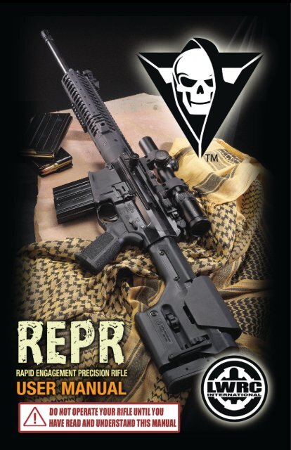
R.E.P.R. - Stevespages.com
R.E.P.R. - Stevespages.com
R.E.P.R. - Stevespages.com

Create successful ePaper yourself
Turn your PDF publications into a flip-book with our unique Google optimized e-Paper software.
LWRC INTERNATIONALINTRODUCTIONThank you for purchasing the LWRCI Rapid Engagement PrecisionRifle (R.E.P.R.). LWRCI’s goal with the R.E.P.R. was to design anddeliver a self-loading rifle that is more reliable, user friendly, and hasaccuracy <strong>com</strong>parable to a bolt-action sniper rifle.R.E.P.R. is loosely based on the proven Stoner AR architecture ofmodular upper and lower receiver groups. Rapidly interchangeableUpper Receiver Groups from the short R.E.P.R. 12 (12.7” barrel) to theR.E.P.R. 20 (20” barrel) allow operators to reconfigure their R.E.P.R.s tomeet and dominate evolving tactical situations.Many of the excellent ergonomics associated with the AR platformare retained. One exception is the side charging handle. The R.E.P.R.employs a left-side non-reciprocating charging handle with anintegrated forward assist. This has the advantage of enabling the userto operate the action while maintaining cheek weld and keepingeyes on target. The location also allows for greater mechanicalleverage during manipulation. Another benefit of eliminating thedorsal charging handle is a tighter fit between the stern of the upperand lower receivers that alleviates gas blowback into the user’s eyeswhen employing the weapon with a suppressor.Our R.E.P.R. rifles feature an adjustable gas system. Four positions(O-Off, S-Suppressed, N-Normal, and A-Adverse) allow for optimumperformance in any situation.Barrel blanks for the R.E.P.R. rifles are cold-rotary hammer forgedon a high-precision mandrel to produce match-grade polygonalrifled blanks which are extremely consistent with outstanding boresurfaces. The blanks are then machined with profiles that maximizeaccuracy and minimize the effects of barrel whip and harmonics.The muzzle has a target crown concentric to the bore to further1
LWRC INTERNATIONAL4.6 Tactical Reload........................................................................................374.7 Operating Cycle............................................................................... 38-395.0 Immediate and Remedial Actions........................................... 415.1 Immediate Action................................................................................. 415.2 Remedial Action.............................................................................. 41-426.0 Maintenance............................................................................ 446.1 Disassembly (Field Strip).............................................................. 44-476.2 Detailed Disassembly.................................................................... 48-556.3 Assembly........................................................................................... 55-566.4 Routine Operator’s Maintenance.............................................. 57-586.5 Detailed Operator’s Maintenance............................................. 58-596.6 Maintenance Procedures - Adverse Climate Conditions.. 59-606.7 Special Arctic Environment Considerations..........................60-616.8 Lubricants and Cleaners...............................................................61-626.9 Rail Maintenance and Notes.......................................................62-637.0 Trouble Shooting........................................................................64-66Warranty ......................................................................................67.1.1 ABOUT THIS MANUAL:The purpose of this manual is to provide instruction on the safeoperation, detail maintenance procedures and provide generalinformation for the R.E.P.R. series of Carbines and Rifles. Thoroughlyread this manual prior to operating your weapon and follow all safetyrules and procedures outlined within. Ensure that you also observeall Local, State, and Federal Laws when possessing, transporting, oroperating your LWRCI firearm.By following the operating and maintenance procedures outlined inthis manual you will ensure proper and safe function of the firearm.1.2 WARNINGS AND SAFETY DATA:WARNING! ALWAYS KEEP THE MUZZLE POINTED INA SAFE DIRECTION WHEN LOADING, UNLOADING,CLEARING OR CHARGING THE WEAPON.WARNING! WHENEVER THE WEAPON IS SUBMERSEDIN WATER IMMEDIATELY SHAKE THE WEAPON,SWINGING THE MUZZLE DOWNWARD VIGOROUSLY,PRIOR TO FIRING TO ENSURE ALL WATER HAS DRAINEDFROM THE BARRELWARNING! NEVER FIRE THE WEAPON WHILE SUB-MERSED IN WATER.WARNING! THE GAS REGULATOR KNOB AND BARRELMAY BECOME HOT ENOUGH TO CAUSE INJURYDURING FIRING. TAKE CARE WHEN CHANGING GASREGULATOR SETTINGS.45
R.E.P.R. MANUALWARNING! ONLY USE AUTHORIZED AMMUNITIONTHAT IS OF THE CORRECT CALIBER AND INSERVICEABLE CONDITION. DO NOT LUBRICATEAMMUNITION.WARNING! WHEN USING A BLANK FIRING ADAPTER(BFA), ENSURE ALL MAGAZINES TO BE FIREDAND EVERY ROUND IN THEM ARE INDEED BLANKAMMUNITION PRIOR TO USING A BFA. FIRING A LIVEROUND WITH THE BFA IN PLACE COULD CAUSEINJURY OR DEATH!WARNING! WHEN FIRING, IF YOU HAVE A DRASTICREDUCTION IN RECOIL AND THE WEAPON DID NOTSOUND RIGHT, UNLOAD TO RANGE SAFE, FIELDDISASSEMBLE AND INSPECT THE BORE TO ENSURETHERE IS NO OBSTRUCTION.WARNING! NEVER FIRE THE WEAPON WITHOUT THECAM PIN INSTALLED. THIS COULD RESULT IN INJURYOR DEATH.WARNING! NEVER KEEP LIVE AMMUNITION NEARFIREARM OR WORK AREA WHILE DISASSEMBLING ORCLEANING FIREARM.GENERAL DESCRIPTION OFTHE R.E.P.R. SERIES OF RIFLES67
R.E.P.R. MANUALLWRC INTERNATIONALThe Rapid Engagement Precision Rifle (R.E.P.R.) series are gas pistonoperated, rotary bolt, magazine-fed, air-cooled, self-loading rifleschambered in 7.62x51mmNATO/.308 Winchester from LWRCInternational, LLC.R.E.P.R.s are available in a number of configurations to fill a variety ofmission profiles:R.E.P.R. 16 – Fitted with a medium profile 16”(406mm) barrel,Enhanced Service Fire Control Group (Semi or Select Fire) andtelescoping EMOD butt stock, this is configured as a Battle Rifle thatcan engage point targets out to 600m.R.E.P.R. 20 – Fitted with a heavy profile 20”(508mm) barrel, 2-stageadjustable match grade trigger and PRS butt stock with adjustablecheek piece and length of pull. It is intended as a precision riflesuitable for engaging point targets out to 800m.R.E.P.R. 12 – Fitted with a medium profile 12.7”(323mm) barrel,Enhanced Service Fire Control Group (Semi or Select Fire) andtelescoping EMOD butt stock, this configuration is intended for useas a heavy caliber Assaulter weapon up to 300m.R.E.P.R. 18 – Fitted with a medium-heavy profile 18”(457mm),2-stage match grade trigger and telescoping UBR butt stock. Thismodel is suitable for use as a Designated Marksman’s Rifle for pointtarget engagements out to 700m.Designed for the rigors of military use, the R.E.P.R. series is extremelyrobust and suited to the demands of field operations without theneed for excessive care and maintenance while maintaining a highlevel of performance.8 9
R.E.P.R. MANUALLWRC INTERNATIONAL2.0.1 TECHNICAL DATA:CaliberWeight(unloaded w/o accessories)7.62x51mm NATO (.308 Winchester)R.E.P.R. 12 - 8.9lbs. (4.03kg)R.E.P.R. 16 - 9.37lbs (4.25kg)R.E.P.R. 18 - 10.5 lbs (4.76kg)R.E.P.R. 20 - 11.17 lbs (5.07kg)2.1 WEAPON NOMENCLATURE:2.1.1 R.E.P.R. 16Length(stock collapsed)R.E.P.R. 12 - 31.3 inches (795mm)R.E.P.R. 16 - 34.5 inches (876mm)R.E.P.R. 18 - 36.4 inches (925mm)R.E.P.R. 20 - 40.5 inches (1029mm)Barrel LengthRiflingMagazine CapacityTrigger Pull (semi)Sustained rate of fireRapid rate of fireRangeR.E.P.R. 12 - 12.7 inches (323mm)R.E.P.R. 16 - 16 inches (406mm)R.E.P.R. 18 - 18 inches (457mm)R.E.P.R. 20 - 20 inches (508mm)6 Lands & Grooves, 1:10” RH Twist5, 10 or 20 roundsR.E.P.R. 12 & 16 - 5.05 - 8.0 lbsR.E.P.R. 18 - 3.2-5.0 lbs (1st stage)0.5-1.5 lbs (2nd stage)R.E.P.R. 20 - 1.3-3.0 lbs (1st stage)0.5-1.5 lbs (2nd stage)5.05 – 8.0 lbs50 rounds per minute120 rounds per minuteR.E.P.R. 20 – 800 metersR.E.P.R. 18 – 700 metersR.E.P.R. 16 – 600 metersR.E.P.R. 12 – 300 metersR.E.P.R. 20 – 1000 metersR.E.P.R. 18 – 900 metersR.E.P.R. 16 – 800 metersR.E.P.R. 12 – 500 metersFig. 2a: R.E.P.R. 16w. EMOD stock - Main Features and Controls1. Muzzle15. Trigger2. Barrel16. Trigger Guard3. Gas Regulator Knob17. Bolt Catch/Release4. Front Sight18. Magazine5. Top Rail19. Pusher Screw6. Rail Handguard Body20. Front Take Down Pin (Hinge Pin)7. Rail Base/ Barrel Nut21. Ejection Port Cover8. Cocking Handle Knob/ Forward Assist 22. Ejection Port9. Receiver Rail23. Magazine Release10. Rear Sight24. Case Delector11. Stock Release Lever25. Ambidextrous Bolt Catch/Release12. Storage Compartment26. Rear Take Down Pin13. Pistol Grip27. Battery Compartment14. Selector LeverItems 11,12 and 27 are only applicable to the EMOD stock.10 11
16. What conditions can be placed on an offender released on bail to ensure the safety of thevictim?Conditions that are placed on an offender who is released on bail may include that he/she abstain from<strong>com</strong>municating with any victim, witness, or any other person named in the order; or refrain from going to anyplace mentioned in the order; or that the accused <strong>com</strong>ply with any other condition specified in the order thatthe justice considers necessary to ensure the safety and security of any victim or witness.When Bill C-79 became law in 1999, it prescribed that the courts must now consider the safety of victims asa specific issue when placing conditions on an accused’s bail. If you have concerns about your safety, askthe Crown about these options.17. What happens if the accused violates the bail conditions?If the accused violates the bail conditions contact the police. Anyone who fails to <strong>com</strong>ply with bailconditions, without lawful excuse, may be found guilty of a summary offence and can be punishedaccordingly. An accused that is arrested and charged with breaching the bail conditions will be held in jailuntil a bail revoke hearing is held. Depending on the type of breech, a judge may release the person,increase the bail money, or impose a sentence. Once that sentence is served, the accused will be releasedagain. If, however, the breech is serious, bail will usually be revoked.18. Will my case go to trial?Most (75-80%) criminal cases are settled by negotiated plea. This means that there will be no trial and asentencing hearing will usually follow. Victims who wish to submit a victim impact statement may do soeven if there is no trial. Your impact statement is important to the court in sentencing, as the judge mustconsider the harm you have suffered in choosing an appropriate sentence for the offender. Your impactstatement is also important to the paroling authorities who will use it at a later time to determine if theoffender is ready to return to the <strong>com</strong>munity. Victims should discuss when/how to submit their statementwith the Crown or the victim services provider. Also, refer to question #118 for more information aboutvictim impact statements.19. What is a plea bargain? Do I have a say?Plea bargaining occurs when the Crown and the defence <strong>com</strong>e to an agreement wherein the accusedpleads guilty. The guilty plea usually <strong>com</strong>es in exchange for a benefit such as reducing the charge againstthe accused or where the two sides agree upon a sentence.If a plea bargain occurs in your case, it does not mean that the offence is less serious or that the Crowndoesn’t believe you. Plea bargaining is often used when either the Crown or the defence’s case is weak. Itis <strong>com</strong>monly used to save both time and money, as the court system could not handle the volume of casesthat <strong>com</strong>e before it without the plea bargaining system. Since Crowns have a good idea of the type ofsentence that a judge is likely to impose for a particular crime, if they can get the accused to agree to a termclose to this, they may not see the benefit of a trial. It is important to note that victims have the right to<strong>com</strong>plete a victim impact statement regardless of whether a trial proceeds or not.Although it is not always the case, Crown Attorneys are supposed to confer with victims of crime beforeproceeding with a plea bargain. Victims appreciate being informed of happenings in their case and aremore likely to accept a plea bargain when the reasons behind it have been explained. It is also important tonote that Crowns do not require a victim’s permission before proceeding with a plea. A plea bargain can bemade at any time including, up to, and during the trial.- 7 -
R.E.P.R. MANUALLWRC INTERNATIONAL2.1.5AR.E.P.R. 16 DISASSEMBLED2.1.5B R.E.P.R. 20 DISASSEMBLED14 15
R.E.P.R. MANUALLWRC INTERNATIONAL2.1.6 OPERATING CONTROLS2.1.6.1 SELECTOR LEVER (14.)Located on the left side of the lower receiver, the selector leverfunctions as the manual safety of the R.E.P.R. and also the firecontrol selector on select fire weapons. The receiver is marked withpictograms of all three modes,SAFESEMI-AUTOMATICAUTOMATICPrevents trigger from releasingthe hammer.Allows one shot per pull of thetrigger.Rifle will shoot and load multipleshots until the trigger is releasedor ammunition runs out.ALL LWRCI rifles are marked with the AUTOMATIC setting, howeverit is only functional in a select-fire weapon (Military and LawEnforcement Only). The AUTOMATIC setting cannot be engaged in asemi-automatic weapon.SAFE can only be engaged when the hammer is cocked by operatingthe charging handle.2.1.6.2 TRIGGER (15.)The Trigger is used to fire the weapon. It is enclosed by the TriggerGuard. The R.E.P.R. 18 is equipped with a 2-stage trigger. It has aheavier and longer 1st stage (approx. 4lbs pull) and a lighter, crisp2nd stage break (approx. 1 lb. pull). The R.E.P.R. 20 is equippedwith an adjustable, 2-stage trigger. Please follow the instructions,provided by Geissele Automatics, for adjusting the trigger.CAUTION: Adjusting the trigger to a very lowpull weight can cause a significant safety issueon a self-loading rifle. LWRCI does not suggestyou adjust the trigger. It has been factory tunedon a precision jig.CAUTION: LWRCI only advocates the use of the firecontrol group supplied with your weapon. Theyhave been thoroughly tested through drop testingand environmental testing to ensure safe use in thefield. There are single-stage match triggers on themarket that, in our opinion, are unsafe for use on anoperational firearm.CAUTION: Installation of aftermarket accessoriesthat extend into the trigger guard area of theweapon is discouraged and could result in anegligent discharge.2.1.6.3 CHARGING HANDLE (8.)The Charging Handle on the left side of the R.E.P.R. is used tocharge the weapon and/or retract the Bolt Carrier Group. It is nonreciprocating.A Forward Assist or Silent Bolt Closure is built into theCharging Handle and is activated by depressing the Charging HandleKnob and pushing forward.NOTE: Depressing the Charging Handle knob while charging aR.E.P.R. will prevent the Bolt carrier Group from retracting fullyand potentially cause a misfeed.2.1.6.4 BOLT CATCH/RELEASE (17. AND 25.)The R.E.P.R. is equipped with ambidextrous bolt catch/release16 17
R.E.P.R. MANUALLWRC INTERNATIONALcontrols on both left (Fig 17) and right (Fig 25) sides of the LowerReceiver. They are used to release the Bolt Carrier Group from thelocked open position or to lock the Bolt Carrier Group back whenthere is a filled magazine or no magazine loaded in the MagazineWell. This is done by depressing the lower portion of either BoltCatch/Release while retracting the Charging Handle all the way tothe rear. Return the Charging Handle to the forward position after.CAUTION: Releasing the Bolt Catch with a loadedMagazine will load the weapon.2.1.6.5 GAS REGULATOR KNOBthe barrel indicates the setting in use. (See Fig.2j) The shape of theregulator is an irregular ellipse to allow the shooter to determinethe active position by touch. Learn the shape of the regulator byremembering the protuberant feature of the knob in relation to alandmark on the weapon.CAUTION: The gas regulator and gas block will beone of the hottest parts of the weapon duringfiring. The regulator knob CAN BE HOT ENOUGHTO BURN YOUR HAND.Closed setting cuts off all gas from the piston system so the weaponwill not cycle when fired. This setting is typically used when it isnecessary to “palm” or retain expended cartridges and/or whenabsolute noise control is a necessity by eliminating the sound of theaction cycling. Typically this is used with subsonic ammunition. Thissetting should be used sparingly as your regulator will be<strong>com</strong>e hardto turn if you fire extensively in closedCAUTION: Always check to make sure the gasregulator is on the correct setting beforeoperational use.Fig. 2j: Gas Regulator set to Normal (N)The Gas Regulator adjusts the volume of gas directed into thepiston. There are 4 detent positions, Closed (marked C), Suppressed(marked S), Normal (marked N) and Adverse (marked A). Themarking that is at 12 o’clock, nearest the top rail and furthest fromSuppressed setting is used in conjunction with Sound Suppressorsto reduce gas backpressure caused by the suppressor. Somesuppressors create more backpressure than others and thereforeyou may not need to use the suppressed setting with your particularsuppressor. If on the Suppressed setting your weapon demonstratessigns of being under-gassed (failure to extract, failure to lock back onan empty magazine) then run your rifle on the N-Normal setting.NOTE: Always follow the instructions supplied by the suppressormanufacturer for installing the suppressor and suppressormount.18 19
R.E.P.R. MANUALLWRC INTERNATIONALNormal setting is the default setting for non-suppressed operation.R.E.P.R.s are tuned for operation with match grade ammunition withheavier weight bullets like M118LR or Federal Gold Medal Match168gr. Ejection with these loads should be at the 4 o’clock position(with muzzle at 12 o’clock). With higher pressure loads , the ejectionpattern should shift to the 2-3 o’clock position. This indicates that thebolt carrier velocity is higher than optimal which may increase thepossibility of a bolt-over-base stoppage.These apply to the EMOD stock on the R.E.P.R. 12 & 16 only27.Adverse setting is only used when the weapon is operatingsluggishly due to extreme and/or very low temperature and/orunderpowered ammunition.11.12.2.1.6.6 STOCK CATCH LEVER (11.)When you first shoot your REPR, use the gas block tool to rotate whilethe weapon is still warm. Work through each of the settings severaltimes then lubricate. This will greatly reduce the likelihood that yourregulator will stick in the future.This Lever is is depressed to allow the EMOD stock to move betweendetent positions. Depress the lever on either side of the ventral riband push/pull the stock2.1.6.6 STORAGE COMPARTMENT (12.)Depress the catch to open the storage <strong>com</strong>partment.2.1.6.7 BATTERY STORAGE (27.)Rotate tab while pulling on the storage cap to remove it. Press backinto place. Holds 4x CR123A batteries each.20 21
R.E.P.R. MANUALLWRC INTERNATIONALThese apply to the PRS stock on the R.E.P.R. 20 only2.1.6.10 EJECTION PORT COVER (21.)31.29.2.1.6.8 CHEEK ADJUSTMENT (29.)This knob is used to raise or lower the height of the Cheek Piece (30.).Facing the left side of the weapon with the stock to the right, theknob is rotated to the left to raise the Cheek Piece and the right tolower it.The ejection port cover is spring loaded with a closing detent. It willautomatically open when the Bolt Carrier cycles and remain openuntil closed manually. The ejection port cover should always bemanually closed after a course of fire and the situation is assessed asnon-threatening.2.1.6.11 PUSHER SCREWS (19.)At the front of the Rail Handguard Body (6.) are the pair of PusherScrews that keep the Top Rail (5.) correctly indexed to the RailHandguard Body. They are captive to the Rail Handguard Body andwill not fall out. The knurled head allows them to be finger tightenedand a slot allows the use of a cartridge rim or coin to torque themtight. Never use excessive force to tighten these screws. There arehigh temperature O-rings that when <strong>com</strong>pressed will prevent thescrews from vibrating loose.2.1.6.9 LENGTH OF PULL ADJUSTMENT (31.)This feature allows the user to optimize your length of pull (buttstocklength) ensuring perfect eye relief with your optic and <strong>com</strong>fort in anoptimal shooting position.The stock should be adjusted to be firm against the shoulder pocketand without neck strain while using the optic. A properly adjustedstock will reduce perceived recoil and enable faster and moreaccurate follow up shots.2223
R.E.P.R. MANUALThese apply to the UBR stock on the R.E.P.R. 18 only34.35.2.1.6.12 STOCK RELEASE LEVER (34.)The length of the UBR stock is adjusted by pulling back on this leverand then moving the lower part of the stock to the desired location.Release to lock.2.1.6.13 STORAGE COMPARTMENT (35.)Depress the latch to open the storage <strong>com</strong>partment.SAFETY INFORMATIONAND PROCEDURES2425
R.E.P.R. MANUALLWRC INTERNATIONALREAD THIS MANUAL COMPLETELY PRIOR TO OPERATING YOURWEAPON.THE FOUR FIREARMS SAFETY RULES1. Treat every weapon as if it were loaded at all times.2. Never point your weapon at anything you don’t intend toshoot.3. Keep your finger straight and off the trigger until you intendto fire.4. Keep your weapon on safe until you intend to shoot.3.1 GENERAL SAFETY PROCEDURES:3.1.1 Whenever handling any weapon, point the muzzle in asafe direction as soon as you pick the weapon up, then CLEAR theweapon. See 3.3.1 to 3.3.5. Ensure chamber is clear.3.1.2 Whenever handing your weapon to another person, clearthe weapon first and hand it over with the bolt locked to the rear bythe bolt catch. When receiving a weapon from another person insistthat they clear it and lock the bolt to the rear before accepting theweapon. Check the chamber to ensure the weapon is clear when youaccept the weapon.3.1.3 Always ensure you are firing the correct caliber ammunitionthrough your weapon. To ensure proper function and safety LWRCIre<strong>com</strong>mends using only factory loaded ammunition that <strong>com</strong>plieswith the Sporting Arms and Ammunition Manufacturer’s Institute(SAAMI), Commission Internationale Permanente pour l’Epreuve desArmes à Feu Portatives (CIP), NATO, or ammunition loaded to U.S.Military specifications for the weapon. LWRCI doesn’t guarantee yourweapon’s safety or performance when utilizing re-loaded or surplusammunition.3.1.4 Check your weapon’s bore to ensure it is free fromobstructions before firing. In the event that the weapon is droppedor the muzzle touches the ground, unload and ensure the weaponbore is free from obstruction. If it is dark and the tactical situationpermits, use a flashlight to ensure there is not an obstruction. If thetactical situation calls for light discipline, drop a cleaning rod throughthe bore to ensure there is no obstruction.3.1.5 Prior to firing your weapon, know your intended target andwhat lies beyond. Ensure that there is an adequate backstop or openspace free from people or any other unintended targets prior toshooting. Never shoot at water or hard objects as ricochets will occurand pose a safety hazard to property, people in the vicinity, or theshooter.3.1.6 Be aware of where the weapon muzzle is pointed at all timesand NEVER flag (point your muzzle at) any person or unintendedtarget regardless of the status of the weapon. When not being carriedon the range your weapon should be placed in Range Safe conditionwith the muzzle facing down range ejection port up, the bolt lockedto the rear and selector on safe. No weapon should be handledregardless of status while people are down range. Observe all rules ofthe range you are firing on.3.1.7 Weapons should be stored unloaded, and in a locked case orother secure area.3.1.8 Always use hearing and eye protection when shooting anyfirearm.3.1.9 Be familiar with your weapon and its features, controls andoperating procedures prior to shooting.26 27
R.E.P.R. MANUALLWRC INTERNATIONAL3.2 WEAPON CONDITIONS:Condition 4: Bolt forward on an empty chamber, ejectionport cover closed, no magazine inserted, and selector leveron fire (will not engage safe). See 3.3Condition 3: Bolt forward on an empty chamber, ejectionport cover closed, magazine inserted, and selector lever onfire (will not engage safe).Condition 2: Not applicable.Condition 1: Bolt forward with a round chambered, ejectionport cover closed, magazine inserted, and selector lever onsafe.Range Safe: Bolt locked to the rear, ejection port coveropen, no magazine inserted, and selector lever on safe.3.3 CLEARING YOUR WEAPON – UNLOADING:3.3.1 Ensure the muzzle is pointed in a safe direction at all timesand through the course of unloading the weapon.3.3.2 Remove the Magazine (if present) by depressing theMagazine Release and either allowing it to drop free or pulling it out.3.3.3 Depress and hold the base of the Bolt Catch with triggerfinger.3.3.4 Grasp the Charging Handle firmly with the support handand pull firmly all the way to the rear. Release the Charging Handle.The bolt carrier should remain locked back.3.3.5 Roll the rifle counterclockwise to visually confirm that thereis no round or casing in the chamber. If light conditions are low,physically inspect chamber.3.3.6 Upon confirmation that the chamber is clear, depress thepaddle of the Bolt Catch. The bolt carrier should move forward andgo into battery.3.3.7 While pointing the weapon in a safe direction, depress theTrigger to render it inert. Your Selector Lever should not go to safe,indicating that the hammer is no longer cocked.3.3.8 Close the Ejection Port Cover. Your rifle is now in Condition 4and ready for administrative handling.CAUTION: Do not depend on the fact that nochambered round was ejected on clearing. Youcan still have a live round in the chamber thatdid not extract/eject because your extractor wasbroken, or if the case rim was ripped through bythe extractor. VISUALLY AND PHYSICALLY inspectthe chamber to ensure it is clear.3.4 PRE-FIRE FUNCTION TEST:The User should always <strong>com</strong>plete a pre-fire function test of the actionand fire control group before using the weapon and any time theweapon has been disassembled and reassembled.3.4a Semi-Automatic Mode3.4.1 Ensure weapon is CLEAR (see 3.3) and in Condition 4 prior toperforming a function test.28 29
R.E.P.R. MANUALLWRC INTERNATIONAL3.4.2 Insert an empty Magazine fully into the Magazine Welland pull downward. The Magazine should remain locked into themagazine well.3.4.3 Grasp the Charging Handle and pull it firmly to the rear. Thebolt carrier should lock to the rear. Return the charging handle to itsforward and locked position by pushing it forward.3.4.4 Depress the magazine release. The magazine should ejectfrom the magazine well and the bolt carrier should remain locked tothe rear.3.4.5 Depress the top serrated portion of the bolt catch. The boltcarrier should spring fully forward and lock into battery.3.4.6 With the selector lever on “SAFE” depress the trigger. Thehammer should not fall.3.4.7 Rotate the selector lever to “SEMI” and depress the trigger.The hammer should fall.3.4.8 Charge the weapon by grasping the charging handle,pulling it firmly to the rear and releasing. Depress and hold thetrigger. The hammer should fall.3.4.9 Continue holding the trigger while charging the weaponagain. Release the trigger as slowly as possible and you should heara click as the disconnector disengages. The hammer should remaincocked.3.4B AUTOMATIC MODE3.4.10 Place the selector lever on “AUTO” Depress and hold thetrigger. The hammer should fall.3.4.11 Continue to hold the trigger and charge the weapon 2-3times. Each time the bolt should go forward and the hammer shouldfall. Release the trigger.3.4.12 This <strong>com</strong>pletes the function check. Make weaponCondition 4.3.5 PRE-FIRE INSPECTION (PFI)Perform the following inspection prior to each firing session. Startyour PFI with your weapon in Condition 4.3.5.1 Break the weapon down “shotgun style” by pulling out theTake Down Pin (26.) and pivoting the Lower Receiver down from theUpper Receiver.3.5.2 Remove the Bolt Carrier Group by pulling the ChargingHandle back all the way and grasping the rear of the Bolt Carrier.3.5.3 Inspect the Bolt and Bolt carrier ensuring the following; theBolt Cam Pin is correctly installed with the arrow facing forward; ifapplicable, the Firing Pin Retainer is fully seated in its hole. Ensure thefiring pin hole is unobstructed and the Firing Pin is properly installed.Tap the bottom of the Bolt Carrier firmly against the palm of yourhand. The Firing Pin should stay in place.3.5.4 Visually inspect the bore of the weapon to ensure it isunobstructed. In low light conditions physically inspect the bore bypassing a cleaning rod through it.30 31
R.E.P.R. MANUAL3.5.5 Re-assemble the weapon inserting the Bolt Carrier Group.Pivot the Lower Receiver back up to the Upper Receiver and press inthe Rear Take Down Pin.3.5.6 Ensure that the Gas Regulator is in the appropriate detentposition as dictated by use.3.5.7 Inspect the Magazines for the following: Ensure theMagazines are clean and not dented (particularly the feed lips).Ensure the Magazine Follower moves freely within the magazinebody and returns under its own spring tension without binding.Do NOT oil or otherwise lubricate magazines. Only use Magazinesre<strong>com</strong>mended by LWRCI.3.5.8 Inspect the ammunition prior to firing. Ensure ammunitionis factory manufactured in <strong>com</strong>pliance with SAAMI, CIP and/or U.S.MIL-Spec/STANAG specifications. Ensure ammunition is the correctcaliber for the weapon. Ensure ammunition is clean. Do not oil orotherwise lubricate ammunition. Do not overload magazines.3.5.9 Put the weapon in Condition 4 or Range Safe status.OPERATION3233
R.E.P.R. MANUALLWRC INTERNATIONAL4.0.1 Choice of AmmunitionAlthough the R.E.P.R. is designed to cycle with a broad spectrum ofammunition, it is optimized for use with heavy bullet loads. With a1-in-10 inch rate of rifling, the barrels are designed to stabilize heavybullets up to 190 grains.The design ammunition is M118LR Match ammunition with the 175grain Sierra Match King bullet. The factory re<strong>com</strong>mends the use ofthis ammunition or similar loads such as the Federal Gold MedalMatch (GMM) and Black Hills 175gr Match. It is suggested to useammunition with bullets heavier than 168 grains for peak accuracy.M80 Ball and equivalent will not realize the true accuracy potentialof the R.E.P.R. It is not suggested you use M118LR or any long rangeload in SBR’s. The slow burn rate of these propellent is not optimizedin short barrels. Reliability and velocity will be adversly affected4.0.2 MagazinesThe R.E.P.R. was designed to use <strong>com</strong>mon magazines with other7.62x51mm NATO rifles currently in use. However, the R.E.P.R. isoptimized and will perform best with the supplied Magpul LR-20magazine. Additional magazines are available from LWRCI.4.1 LOADING A MAGAZINE4.1.1 Grasp the Magazine firmly in your support hand.4.1.2 Push the round under the magazine feed lips. The baseof the cartridge should be all the way back against the back of themagazine.4.1.3 Repeat until the magazine is filled. DO NOT OVERFILL themagazine.4.2 LOADING A WEAPON IN CONDITION 4Starting with the weapon in Condition 4:4.2.1 Insert a loaded magazine firmly into the Magazine Well.Ensure the magazine is fully seated by tugging on it.4.2.2 Charge the weapon by firmly pulling the charging handle tothe rear and releasing it (“slingshot” method).4.2.3 Rotate the selector to “SAFE”. If not immediately firingthe weapon close the ejection port cover. The Weapon is now inCondition 1.4.3 FIRING IN SEMI-AUTOMATIC MODEStarting with a weapon in Condition 1:4.3.1 Bring Weapon to the “Ready” position.4.3.2 Acquire and Aim at the intended Target.4.3.3 Put Selector to “SEMI”.4.3.4 Depress trigger with a deliberate squeezing motion of thestrong hand index finger to fire individual shots. Repeat until target isneutralized.4.3.5 Scan and assess for threats or targets.4.3.6 Put Selector to “SAFE”.4.3.7 Close Ejection Port Door.34 35
R.E.P.R. MANUALLWRC INTERNATIONAL4.4 Firing in Automatic Mode (only in Select Fire weapons)Starting with a weapon in Condition 1:CAUTION: Auto should only be considered operationallyif the user has had sufficient training and practice on thissetting4.4.1 Bring Weapon to the “Ready” position.4.4.2 Acquire and Aim at the intended Target.4.4.3 Put Selector to “AUTO”.4.4.4 Depress trigger with a deliberate squeezing motion of thestrong hand index finger to fire bursts. Release trigger to discontinueburst. 3-5 round bursts are optimal. Repeat until target is neutralized.4.4.5 Scan and assess for threats or targets.4.4.6. Set Selector to “SAFE”.4.4.7. Close Ejection Port Door.4.5 RELOADING FROM BOLT LOCKWhen the Magazine is out of ammunition, the Bolt Catch isautomatically engaged. The Bolt Carrier Group is held open. Theweapon will not fire. To Reload:4.5.1 Depress the Magazine Release. Pull the Magazine out of themagazine well and allow it to fall to the ground.4.5.2 Retrieve a loaded Magazine with your support hand.4.5.3 Insert loaded Magazine into Magazine Well. Ensure themagazine is fully seated by tugging on it.4.5.4 Depress the Bolt Catch from either side of the weapon.This will allow the Bolt Carrier to go into battery and chamber around. Weapon is now in Condition 1.4.5.5 Scan and assess for threats or targets. Re-engage asnecessary.4.5.6 Set Selector to “SAFE”.4.5.7 Close Ejection Port Door.4.6 TACTICAL RELOADA tactical reload is carried out during a lull in <strong>com</strong>bat to keepthe weapon topped up with ammunition. It is conducted fromCondition 1:4.6.1 Retrieve a loaded Magazine with your support hand. Graspthe base of it with thumb and index finger.4.6.2 Grasp partially empty Magazine between 2 digits of supporthand. Depress the Magazine Release. Remove the Magazine by hand.4.6.3 Insert loaded Magazine into Magazine Well. Ensure themagazine is fully seated by tugging on it.4.6.4 Stow partially empty magazine appropriately.4.6.5 Scan and assess for threats or targets.4.6.7 Close Ejection Port Door.36 37
R.E.P.R. MANUALLWRC INTERNATIONAL4.7 OPERATING CYCLEThe following describes the operating cycle of the R.E.P.R. in semiautomaticmode.FiringUnlockingWhen the Trigger is depressed, the sear is disengaged from theHammer allowing the hammer to be driven by the Hammer springto strike the Firing Pin. The Firing Pin strikes the primer, firing thechambered round.Propellant gasses are tapped off at the gas port and travel trough thegas block to the nozzle. This gas drives the piston cup back from thenozzle, in turn driving the operating rod to strike the carrier key. Thisinitiates the rearward movement (recoil stroke) of the Bolt CarrierGroup. As the Bolt Carrier travels to the rear, the Cam Pin rotates theBolt, thus unlocking it from the barrel extension.FeedingChamberingThe recoil stroke concludes when the Buffer halts the Bolt CarrierGroup. The Recoil Spring, <strong>com</strong>pressed during the recoil stroke, drivesthe bolt carrier group forward <strong>com</strong>mencing the counter-recoil stroke.As the Bolt Carrier returns forward the next round is stripped fromthe top of the Magazine and directed into the chamber by the feedlips of the magazine and the feed rampsAs the bolt carrier group continues the counter-recoil stroke theround is seated in the chamber.ExtractionEjectionAs the Bolt Carrier Group continues through the recoil stroke theexpended cartridge is drawn from the chamber by the extractor.Once the expended cartridge is clear of the chamber it is ejectedfrom the weapon by the spring loaded Ejector.LockingAs the bolt carrier group <strong>com</strong>pletes the counter recoil stroke the boltrotates, locking into the barrel extension. The bolt carrier group isnow again in battery.CockingSemi -As the Bolt Carrier Group continues to the rear it cocks theHammer which is initially retained by the Disconnector. As theshooter disengages the trigger, the Disconnector releases thehammer allowing it to be captured by the Trigger (this is known asReset).Auto - As the bolt carrier group continues to the rear it cocks thehammer which is retained by the auto sear. Concurrently the rearof the bolt carrier will trip the auto sear releasing the hammer andfiring the round. When the trigger is depressed and held, the weaponwill cycle continuously through the firing sequence until the triggeris released or the magazine is depleted. When the user releases thetrigger, the hammer is caught by the hammer/trigger engagementsurface and does not allow the weapon to fire again until the triggeris pulled.38 39
R.E.P.R. MANUALLWRC INTERNATIONAL5.1 IMMEDIATE ACTIONImmediate Action is defined as the prompt action taken by theoperator to reduce a stoppage without investigating the cause.A stoppage is defined as any interruption in the operating cycle.It is suggested to transition to a secondary weapon if cover is notavailable, or if the situation permits perform the following:5.1.1 Keep the weapon shouldered and in the ready positionpointed downrange.5.1.2 Ensure the magazine is fully seated by pushing themagazine up into the mag well and then tugging firmly down toensure it is securely engaged.5.1.3 Pull the charging handle to the rear and release in aslingshot motion. DO NOT ride the charging handle forward.5.1.4 Re-engage the target.IMMEDIATE AND REMEDIAL ACTIONS5.1.5 If the weapon does not eject a casing or live round applyRemedial Action.5.2 REMEDIAL ACTIONRemedial Action is defined as the actions taken by the operator toremedy a Malfunction. A Malfunction is defined as a failure of theweapon to operate as designed. A simple way to remember the stepsof a remedial action is to simply “Unload” the weapon, and “Reload”the weapon once the weapon is clear.5.2.1 Attempt to set the Selector Lever to “SAFE”.40 41
R.E.P.R. MANUAL5.2.2 Lock the Bolt Carrier Group to the rear by depressing thebottom segment of the Bolt Catch and pulling the Charging Handleto the rear. Return the Charging Handle to the forward position.5.2.3 Remove and discard the Magazine.5.2.4 Roll the rifle 60 degrees counter-clockwise to visually inspectthe chamber for obstructions.5.2.5 Shake or attempt to clear any stoppage via the Magwell orEjection Port.5.2.6 Check Gas Regulator to ensure it is at an appropriate setting.5.2.7 Release the Bolt Catch and manipulate the Charging Handleat least three (3) times to ensure the action is functioning properly.5.2.8 Make the weapon Condition 1 weapon and continue themission.MAINTENANCE42
R.E.P.R. MANUALLWRC INTERNATIONALProper maintenance of a weapon requires not only immediate preand post firing cleaning but also the replacement of consumableparts to ensure 100% of the reliability and accuracy of the productthroughtout its lifetime. Keep an accurate log of every round firedthrough the weapon. Even writing down an estimate of the numberof rounds fired on a given day will help you perform scheduledmaintenance on the system.6.1.2. (Fig. 6a) Pull out the Take Down Pin by pushing from the leftside of the Lower Receiver to start the pin moving then pull out fromthe right. A dowel or bullet tip can be helpful. The pin detent will bestiff on a new rifle. This will get easier as you use and disassembleyour R.E.P.R.This is an operators manual and does not cover replacement of partsoutside those that can be replaced on a Detailed Strip (as decribedin section 6.2 of this manual). It is encouraged that only a certifiedarmorer should diassemble and replace parts beyond those removedduring a field strip.6.1 DISASSEMBLY (FIELD STRIP)Frequency: The weapon should be disassembled to its majorgroups and assemblies when conducting Routine Operator LevelMaintenance (as determined by unit). For convenience the UpperReceiver can remain connected to the Lower Receiver (weaponbroken down “shotgun style”) during Routine Operator LevelMaintenance.Fig. 6A: Pushing in the Take Down PinTIP: Lay your parts out from left to right in the sequence theywere removed from the weapon so upon reassembly, you justwork right to left. This procedure will also be useful if you haveto strip and reassemble the weapon in the dark.(Fig. 6a) Pull the pin from the right as far as it goes. The pin will remain captive. This pinreleases the back end of the upper receiver from the lower receiver.The sequence is as follows:6.1.1 Clear the weapon (refer to Section 3.3 of this manual) andensure the weapon is Condition 4. Your Bolt Carrier must be inbattery.44 45
R.E.P.R. MANUALLWRC INTERNATIONAL6.1.3 (Fig. 6b) Pivot the Lower Receiver until it is 90° to the UpperReceiver. Pull out the front take down pin and disconnect the upperfrom the lower <strong>com</strong>pletely.6.1.5 Remove the Buffer and Buffer/Recoil Spring by depressingthe buffer detent (Fig. 6c) Pull the buffer and spring from the lowerreceiver (Fig. 6d).Fig. 6C: Depress the Buffer DetentFig. 6B: Pivot apart the receivers6.1.4 Pull the Charging Handle back all the way and grasp the rearof the Bolt Carrier. Remove it from the receiver. Return the ChargingHandle to the forward positionFig. 6D: Remove Recoil Buffer and Recoil Spring6.1.6 Remove the Recoil Buffer from the Recoil Spring. The R.E.P.R.is now Field Stripped.46 47
R.E.P.R. MANUALDUPLICATE PHOTOLWRC INTERNATIONAL6.2 DETAILED DISASSEMBLYThis level of disassembly is for Detailed Operator Level Maintenanceof the R.E.P.R. Care must be taken to ensure that small parts are notlost. The use of a cloth or tarpaulin to catch them is encouraged.Further disassembly is not required for operator authorizedmaintenance and should only be performed by higher echelonmaintenance personnel.6.2.2c Ensure the Bolt is retracted into the Bolt Carrier and rotatethe Bolt Cam-Pin 90° counter-clockwise. Pull to remove the Bolt CamPin6.2.1 Clear and Field Strip the weapon by following theinstructions in the previous section.6.2.2 Bolt Carrier Disassembly6.2.2aCarrier.(Fig. 6G) Remove the Firing Pin Retaining Pin from the Bolt6.2.2b (Fig. 6H) Turn the carrier so the Bolt is facing upward and tapagainst a surface to remove the Firing Pin.Fig. 6G: Removing the Firing pin Retaining pinFig. 6G: Removing the Firing pin Retaining pinFig. 6H: Tap the Carrier to dropthe Firing Pin48 49
R.E.P.R. MANUALLWRC INTERNATIONAL6.2.2cOnce the Cam Pin is removed, pull forward on theBolt Assembly to remove it form the Carrier.6.2.3a (Fig. 6m) Utilize the Firing Pin to push the Extractor Pin andstart it out of the bolt.Fig. 6K: Remove the Bolt AssemblyFig. 6L: (L-R) Bolt, Extractor, Extractor Pin, Extractor Spring6.2.3 Bolt DisassemblyAt the Operator level, no further disassembly of the bolt beyondremoving the Extractor is necessary.6.2.3b Grasp the pin from the opposite side and remove it. Turnthe Bolt over and tap the Extractor out into your palm. Be sure not tolose the extractor springs and o-ring. See Fig. 6L for a description ofthe parts.Fig. 6M: Remove the Extractor Pin50 51
R.E.P.R. MANUALLWRC INTERNATIONAL6.2.4 Upper Receiver Group DisassemblyStart from a Field Strip condition. Pull out the Forward Take-down Pinto its stop. Start by pushing the pin from the left side of the receiver.Then pull from the right. Separate the upper and lower receiver.6.2.4a (Fig. 6n) Remove the Top Rail by loosening the two PusherScrews and pushing the upper rail forward(Fig. 6p) then lift up (Fig. 6q) and remove.NOTE: The two Pusher Screws are captive and are not supposedto <strong>com</strong>e free from the Rail handguard Body.Fig. 6P: Push the Top Rail ForwardFig. 6N: Loosen Pusher ScrewsFig. 6Q: Lift and remove Top Rail52 53
R.E.P.R. MANUALLWRC INTERNATIONAL6.2.5 Piston Operating Group Disassembly6.2.5a To disassemble the Piston Operating Group assembly, graspthe front of the operating rod and pull firmly to the rear <strong>com</strong>pressingthe piston spring while pulling forward on the Piston Cup (Fig. 6r).Ensure to pull it straight back into the receiver or it will bind. Thefront of the operating rod will disengage from the piston cup.NOTE: If disassembling only the gas piston <strong>com</strong>ponents on anotherwise assembled rifle, lock the bolt to the rear while disassemblingor assembling the gas piston <strong>com</strong>ponents to relievethe recoil spring resistance.Fig. 6S: Pull Piston Rod forward and clear6.2.5c Pull the piston cup to the rear and off of the nozzle. This<strong>com</strong>pletes detailed disassembly.6.3 ASSEMBLYAssembly of the R.E.P.R. series is ac<strong>com</strong>plished by reversing thedisassembly steps. During reassembly take note of the following:6.3.1 When reinstalling the Operating Rod Assembly, rotate theAssembly until it fully seats in the Piston Cup.Fig. 6R: Grasp cup and pull back on Piston Rod6.2.5b Lift out the front of the operating rod assembly and pull itforward then away from the receiver. (Fig. 6s)6.3.2 When reinstalling the Buffer and Buffer Spring, push theBuffer fully past the buffer detent and ensure it is captured behindthe detent.6.3.3 When reinstalling the Extractor, line up the holes by pressingfirmly on the center of the Extractor while reinstalling the extractorpin.54 55
R.E.P.R. MANUALLWRC INTERNATIONAL6.3.4 While reinstalling the Firing Pin Retaining Pin ensure theFiring Pin is fully forward and the Firing Pin Retaining Pin is installedfrom left to right when looking from the rear of the weapon. WhileBolt is pushed rearward into Carrier, push end of Firing Pin towardfront of Bolt and ensure it protrudes through the face of the Bolt.6.3.5 When reinstalling the Bolt Carrier Group into Upper Receiver,ensure that the Bolt is fully extended.6.3.6 When closing the Upper and Lower Receiver, pivot theLower Receiver to the Upper receiver until contact is made. Thenpush the Rear Take Down Pin all the way into the Lower Receiver. Itmay be necessary to push the Upper and Lower Receivers togetherto enable this.6.4 ROUTINE OPERATOR’S MAINTENANCE:Perform routine maintenance after each firing session or once dailywhile operating in normal field conditions. Ensure weapon is clearprior to performing any maintenance. When punching the weapon’sbore pass the cleaning rod through the chamber end towardsthe muzzle. Otherwise the muzzle may be damaged and degradeaccuracy.6.4.1 Field-strip the weapon as detailed in Section 6.1.6.4.2 Clean bore by punching first with a patch saturated inSimple Green, SLIP 2000 Carbon Killer or approved solvent. Punchbore with bore brush several times. Punch with a dry patch toremove carbon residue and cleaning solvent.NOTE: If you see a degradation in accuracy clean bore using a coppersolvent per solvent manufacturer’s instructions.6.4.3 Check for cleanliness by punching with a clean patch. If thepatch does not <strong>com</strong>e out clean, repeat steps 6.42 until it does.6.4.4 Wipe Bolt Carrier, Charging Handle, interior of UpperReceiver, Buffer and Buffer Spring with a cloth (slightly dampenedwith cleaning solvent if available).6.4.5 Scrub the face of the bolt with a GP brush dipped in cleaningsolvent or CLP. Thoroughly wipe away any remaining cleaning solventor CLP with a rag.6.4.6 Apply a light coat of lubricant to the interior of the upperreceiver, buffer spring, <strong>com</strong>pensator and ejection port cover.56 57
R.E.P.R. MANUALLWRC INTERNATIONAL6.4.7 Apply point lubricant to the Extractor, Bolt Cam Pin, Hammerpivot point, and Trigger pivot point, Charging Handle Knob, BoltCatch, and Carrier sear. (NOTE: Do not lubricate the face of the bolt.)6.4.8 Reassemble weapon and perform functions check asdetailed in Section 3.4 and 3.5.6.5 DETAILED OPERATOR’S MAINTENANCEPerform Detailed Maintenance every 2,000 rounds or once weeklywhile operating in normal field conditions. Ensure weapon is clearprior to performing any maintenance.6.5.1 Detail Disassemble weapon as described in Section 6.2.6.5.2 Perform Routine Maintenance as detailed in the previoussection.6.5.3 Scrub extractor with GP brush dipped in cleaning solvent orCLP. Pay particular attention to remove any built up brass deposits inthe extractor groove. Thoroughly wipe away any remaining cleaningsolvent or CLP with a rag.6.5.4 Scrub Bolt Carrier, Bolt Body, Firing Pin and interior ofthe Upper Receiver with GP brush dipped in cleaning solvent orCLP. Punch firing pin hole and firing pin cavity with a pipe cleaner.Thoroughly wipe away any remaining cleaning solvent or CLPwith a rag. Apply a moderate coat of lubricant to the inside of theBolt Carrier where the bolt installs. Apply point lubrication to theExtractor where the pin installs and the Bolt Cam Pin when it isinstalled. Apply a light coat of lubricant to the interior of the upperreceiver prior to re-installing the Bolt Carrier Group.6.5.5 Scrub Gas Piston Nozzle with a dry brass wire brush. Wipeaway any remaining carbon residue with a rag and cleaning solvent.(NOTE: The gas piston nozzle should be <strong>com</strong>pletely dry beforereassembling the weapon. Lubrication may cause fouling whenfired.)6.5.6 Scrub the Gas Piston Cup inside and out with a dry brasswire brush. Apply a light coat of lubricant to the outside of the pistoncup and wipe off any excess lubricant or residue with a rag.NOTE: As a general practice, do not introduce any lubricant intothe inside of the piston cup as this may cause fouling when fired6.5.7 If the weapon is to be stored for a longer period of time,place a light coating of CLP on the Nozzle and reassemble. Theuser can wipe off the excess prior to firing. It is inconsequential tofunction if the user does not wipe off excess CLP prior to firing, but itmay cause some smoke as the lubricant burns off with an aggressivefiring schedule.6.5.8 Scrub the Operating Rod Assembly with a GP brush dippedin cleaning solvent or CLP (these will be very clean to start with asthey are not directly exposed to carbon). Thoroughly wipe away anyremaining cleaning solvent or CLP with a rag. Apply a light coat oflubricant to the Operating Rod Assembly.6.5.9 Reassemble weapon and perform functions check asdetailed in Sections 3.4 and 3.5.6.6 MAINTENANCE PROCEDURES FOR ADVERSE CLIMATECONDITIONS6.6.1 When operating in adverse environments LWRCInternational re<strong>com</strong>mends utilizing shoot through muzzle covers andgun covers (tactical situation permitting).58 59
R.E.P.R. MANUALLWRC INTERNATIONAL6.6.2 Pay particular attention that the Ejection Port Cover isclosed at all times when not firing your weapon. If weapons must begrounded stuff a rag into the Magazine Well.6.6.3 In blowing sand or snow conditions conduct frequentfunctions checks of your weapon and take every opportunity toremove sand or snow from your weapon. A small paint brush ishighly re<strong>com</strong>mended for this task. Blow sand from weapon with<strong>com</strong>pressed air if available.6.6.4 Do not lubricate the interior of the Upper Receiver orexterior of the Gas Piston <strong>com</strong>ponents when operating under fieldconditions in extremely sandy or snowy environments.6.6.5 When performing routine maintenance remove the Top Railand brush any sand or snow from the piston <strong>com</strong>ponents.6.6.6 Apply point lubrication as sparingly as possible.6.7 SPECIAL ARCTIC ENVIRONMENT CONSIDERATIONS6.7.1 Keep weapons at ambient outdoor temperature wheneverpossible and use an arctic rated lubricant.6.7.2 If weapons must be brought into a warm area, allowweapons to warm up to the room temperature, detail disassembleand perform Detailed Maintenance. Pay particular attention toremoving all condensation from weapon before going back into coldtemperatures.6.7.3 Even if weapons are kept outdoors, temperatures canfluctuate above and below freezing causing condensation andfreezing in the weapon’s moving <strong>com</strong>ponents. Perform frequentfunctions checks to ensure weapon is operable.6.7.4 If weapon is dropped in the snow clean it immediately. Ata minimum break the weapon down shotgun style and remove anysnow from the upper receiver and bolt carrier. Clean snow from gaspiston <strong>com</strong>ponents. Ensure bore is clear.6.7.5 If your weapon does freeze shut DO NOT FIRE IT to un-jamthe weapon. Warm weapon with body heat or a camp stove (holdweapon at least eight inches above flame and remove magazineprior to warming) until un-jammed then clean or fire immediately.Keep muzzle pointed in a safe direction.6.8 LUBRICANTS AND CLEANERSThe R.E.P.R. is <strong>com</strong>patible with all standard U.S. Military and NATOspecified small arms lubricants and cleaners. The manufacturerre<strong>com</strong>mends SLIP 2000 EWL (Extreme Weapons Lubricant for 1.0oz tube). If changing from one lubricant to another clean off oldlubricant by scrubbing parts with solvent, e.g. Simple Green or SLIP2000 Carbon Killer.Lubrication Terms:Light Coat- A light coat of lubricant is not readily visible to the eye.Apply lubricant and wipe off excess with a clean cloth.Moderate Coat- A moderate coat of lubricant should be just visibleto the eye. Apply lubricant directly to part and spread or apply with abrush, cloth or finger.Point Lubrication- Lubrication applied to pivot points or recessedparts. Apply a couple of drops to the pivot point and work part backand forth to distribute lubricant.60 61
R.E.P.R. MANUALLWRC INTERNATIONAL6.9 RAIL MAINTENANCE AND NOTESThe R.E.P.R. features a free floated user configurable rail system. Therail does not <strong>com</strong>e into contact with any part of the barrel allowingthe use of accessories, a bipod or the rail itself as a support surfacewithout affecting the point of impact of the bullet. The rail has amonolithic profile 12 o’clock rail that perfectly mates to the rail onthe upper receiver allowing the stacking of sighting devices. The 3,6, and 9 o’clock rail sections are user configurable. You can installone of several available rail sections to any portion of the rail tubedependant on where you usually mount your accessories. This wasdone to cut the weight of the rifle, and make the user interface withthe system more <strong>com</strong>fortable.6.9.1 There is no required rail maintenance other than protectingthe M1913 Picatinny rail sections that remain exposed to damagewith a rail or ladder panel. The R.E.P.R. rails can be set up for usewith LWRCI Rail Skinz or USGI issue rail panels. Any Picatinny 1913standard rail panel will work.6.9.3 The barrel nut of the R.E.P.R. also acts as the rail mount. It isnot re<strong>com</strong>mended you remove the rail of the R.E.P.R. as there is norequirement to do so at the operator level.6.9.4 There are small C-Clips that make the pusher screw captive.In the rare event this be<strong>com</strong>es dislodged or lost, a standard C-Clipfor an M16 ejection port rod can be used. With the top rail removed,screw in the pusher screw all the way. With needle nose pliers, installthe C-Clip to the groove toward the nose of the pusher screw.6.9.5 During normal use, the rail will be<strong>com</strong>e fouled with carbonand some copper residue from jacketed ammunition. If left, thecopper will turn a blue/green color. This is purely cosmetic and willnot adversely affect the weapon. You can remove it with a coppersolvent. You should always inspect the inside of the top rail to ensurethe fouling does not interfere with piston operation. Some wear onthe inside of the Top Rail is normal.6.9.2 There are several configurations of rails and sling adapterrail sections available. Please see the LWRCI Web-Store to orderadditional rail sections, lengths and configurations. To install a railsection, use the supplied Allen head machine screws (they havepre-applied thread-locker already applied and are not standardmachine screws). Match the installation holes on the rail section tothe appropriate holes in the rail system. Install the screws using a5/64” Allen wrench to no more than 15 inch/lbs. If you remove theAllen head screw to reposition a rail section, ensure you degrease thescrew and the hole with a suitable degreasing solution (e.g. alcohol,acetone etc.). Apply blue Lock-Tite or suitable medium-strengththread locker to the screw before installation.62 63
R.E.P.R. MANUALLWRC INTERNATIONAL7.0 TROUBLE SHOOTINGNOTE: When shooting with a silencer or suppressor please note thefollowing:7.1 Follow Manufacturer’s instructions for mounting/dismounting suppressor, for care and use.Leading of feed ramps from use of Non- Disassemble and clean feed ramps andFMJ (Full Metal Jacket) ammunition use jacketed ammunitionFailure to LockCAUSECORRECTIONUse proper SAAMI/CIP/ NATO Spec.Wrong ammunition for chamberAmmunition.7.2 Use suppressor design with same caliber of weapon.7.3 Ensure suppressor is firmly attached prior to use.7.4 Cyclic Rate will be increased.FOD (Foreign Object Detected) inchamber or barrel extensionAmmunition defective/damaged or outof specificationWeak/worn Buffer/Action SpringDisassemble and clean rifle.Inspect all ammunition prior to use andensure SAAMI/CIP/NATO <strong>com</strong>pliant.Replace spring.7.5 Gas/fouling will be increased.7.6 Weapon shall require an increase in lubrication and cleaning.7.7 If running a suppressor for an extended period, or if thesituation permits, turn the Gas Regulator to the Suppressed (S)setting.Failure to FireCAUSECORRECTIONDefective ammunition/dead primerInspect all ammunition prior to use andensure SAMI/NATO <strong>com</strong>pliant.Broken/weaken hammer springReplace spring.CAUSEFailure to LoadCORRECTIONFOD (Foreign Object Detected) in PinChannel (Fire Control Group)Disassemble and clean.Bent/damage magazine feed lips orWorn/Weak magazine feed springWorn out/under powered recoil springInspect Magazine and replace asnecessaryReplace spring. Do not try to stretch.Worn Firing PinCarrier Bounce/Bolt BounceReplace firing pinAdjust Gas Regulator to smaller setting.Use lower pressure ammunition.Under powered ammunition (Cause-Short Stroke)Use SAAMI, CIP or NATO Spec.AmmunitionForeign Objects & Debris (FOD) in FireControl Group (FCG)Disassemble and clean.64 65
EXPORT CONTROLUser acknowledges that any technical data furnished by LWRCI inconnection with this order may be subject to U.S. export control laws,including but not limited to the Arms Export Control Act, 22 USC§ 2778, (AECA) and the International Traffic in Arms Regulations,22 CFR 120-130, (ITAR) promulgated pursuant thereto. In thisregard, User agrees that, unless it has obtained prior written consentfrom the U.S. Department of State, Directorate of Defense TradeControl (DDTC), they will not export, reexport, or transship, directlyor indirectly, the goods, documentation, technical assistance, or anymedia in which any of the foregoing is contained, or other technologyprovided hereunder or the direct product thereof, to any country or toany non-U.S. citizen.CONTACT INFORMATIONMonday thru Friday: 8am thru 5pm ESTCustomer Service DepartmentLWRC International, LLC815 Chesapeake DriveCambridge, MD 21613410-901-1348 Fax 410-228-1775Email: customerservice@lwrci.<strong>com</strong>All NFA and GCA rules and laws apply to any purchase of LWRCIfirearms. Please check local, state, and federal laws.R.E.P.R. PATENTS PENDINGNo part of this document may be copied, reproducedor transmitted by any means, for any purpose withoutprior written permission fromLWRC International, LLC.All images and text © 2009,2010 LWRCI68
LWRCINTERNATIONALLWRC INTERNATIONAL, LLC815 CHESAPEAKE DRIVECAMBRIDGE, MD 21613410.901.1348410.228.1775 FAXWWW.LWRCI.COM015-000201/04/11Rev. B