OVERHEAD LINE SPLICES
OVERHEAD LINE SPLICES
OVERHEAD LINE SPLICES
- No tags were found...

You also want an ePaper? Increase the reach of your titles
YUMPU automatically turns print PDFs into web optimized ePapers that Google loves.
DISTRIBUTION PRODUCTSINDEXSection DAdeadendsSERIES DESCRIPTION PAGEautomatic/copperGD500/GD100.... RIGID CLEVIS, SEMI-FLEX, FLEX OR Z BAILS...........................................DA-1automatic/aluminumGD400................. RIGID CLEVIS, SEMI-FLEX, FLEX OR Z BAILS..................................DA-2/DA-3GDW................... <strong>OVERHEAD</strong> SIDE OPENING WEDGE..........................................................DA-4GDW2000........... <strong>OVERHEAD</strong> SIDE OPENING WEDGE..........................................................DA-5automatic/aluminum-stainless steel bailGDE5100............ GUY WIRE AUTOMATIC................................................................................DA-6GDE5200............ GUY WIRE AUTOMATIC................................................................................DA-7bolted/steel6400.................... GUY WIRE, BOLTED (GUY CLAMP).............................................................DA-8bolted/aluminumADES.................. STRAIGHT <strong>LINE</strong> CLAMP WITH STIRRUP..................................................DA-14ADEZ/ADSO....... STRAIGHT <strong>LINE</strong> SPRING-LOADED SIDE OPENING CLAMP...................DA-11ADS..................... STRAIGHT <strong>LINE</strong> STRAIN CLAMP...............................................................DA-13ADSB.................. STRAIGHT <strong>LINE</strong> SINGLE BOLT SIDE OPENING CLAMP..........................DA-10AR1/AR2............. QUADRANT STRAIN CLAMP......................................................................DA-18ASOD.................. STRAIGHT <strong>LINE</strong> SIDE OPENING CLAMP....................................................DA-9GD900................. STRAIGHT <strong>LINE</strong> STRAIN CLAMP (SWING AWAY)....................................DA-12GM100................ IN-SPAN NEUTRAL TAP..............................................................................DA-30GM100A.............. MIDSPAN CLAMPS AND DEADENDS........................................................DA-28GM128................ IN-SPAN PHASE CONNECTOR AND HOUSING........................................DA-29PG/DE................. QUADRANT STRAIN CLAMP......................................................................DA-17SD....................... QUADRANT STRAIN CLAMP......................................................................DA-15SDT2................... DOUBLE GROOVE QUADRANT CLAMP....................................................DA-16bolted/bronzeBDE..................... STRAIGHT <strong>LINE</strong> STRAIN CLAMP...............................................................DA-21BR1/BR2............. QUADRANT STRAIN CLAMP......................................................................DA-25BSC/BSCG.......... STRAIGHT <strong>LINE</strong> STRAIN CLAMP...............................................................DA-23BSD/BSDS.......... QUADRANT STRAIN CLAMP......................................................................DA-24BSG..................... STRAIGHT <strong>LINE</strong> STRAIN CLAMP...............................................................DA-22bolted/ferrous7850*2000........... CIRCULAR DEADEND CLAMP...................................................................DA-26876*2000............. STRAIGHT <strong>LINE</strong> STRAIN CLAMP...............................................................DA-198****2000............. CIRCULAR DEADEND CLAMP...................................................................DA-26DDC.................... CIRCULAR DEADEND CLAMP...................................................................DA-26MDE.................... STRAIGHT <strong>LINE</strong> STRAIN CLAMP...............................................................DA-19SWDE/MD........... QUADRANT STRAIN CLAMP......................................................................DA-20HUBBELL ® Power Systems December 2011
DISTRIBUTION PRODUCTSINDEXSection DADEADENDScontinuedSERIES DESCRIPTION PAGETHIMBLE/ALUMINUMADET................... ALUMINUM DEADEND THIMBLE...............................................................DA-27THIMBLE/DUCTILE-IRONDDT..................... DUCTILE DEADEND THIMBLE...................................................................DA-27ALUMINUMMSE.................... ALUMINUM MID-SPAN CONNECTOR........................................................DA-32MSN.................... ALUMINUM MID-SPAN CONNECTOR........................................................DA-31MSNT.................. ALUMINUM MID-SPAN CONNECTOR........................................................DA-31TTSB................... ALUMINUM SUPPORT BRACKET..............................................................DA-32December 2011HUBBELL ® Power Systems
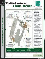
• Fastest method of deadending Copper and Copperweld ®conductor.• Flared mouth of gripping unit permits easy conductorinstallation.• Four segment jaw is precision machined andautomatically adjusts to the contour of the wire.• High strength alloy copper tube for gripping Copperweld ®conductors• Available with galvanized steel stirrup clevis or stainlesssteel Z bail for primary applications.Material: Shell – High strength Copper AlloyJaws – Copper AlloyClevis Bail – Galvanized steelZ Bail – Stainless Steel, formed wireFlex Bail – Braided stainless steelSemi-flex Bail – Stainless Steel, formed wireDISTRIBUTION CONNECTORSDEADENDSAUTOMATICCOPPERSECTION DACOPPERGD500/GD100DA1CLEVISBAILCATALOG NUMBERZBAILFLEXBAILSEMI-FLEXBAILSOLIDASTM-B258CONDUCTOR RANGECOPPERSTRANDASTM-B8COPPERWELDSTRANDAPPROXIMATECONDUCTOR O.D.INCHES (MM)- - GD110 GD110R 8 - - .12-.13 (3.1-3.3)GD511 GD111Z GD111 GD111R 6 - - .16-.17 (4.0-4.4)GD512 GD112Z GD112 GD112R 4 - 8A .19-.20 (4.9-5.2)GD513 GD113Z GD113 GD113R 3 4 6A .22-.23 (5.7-5.9)GD514 GD114Z GD114 GD114R 2 3 5A .25-.26 (6.3-6.6)GD515 GD115Z GD115 GD115R 1 2 4A .28-.29 (7.2-7.4)GD516 GD116Z GD116 GD116R 1/0 1 3A .32-.33 (8.1-8.3)GD517 GD117Z GD117 GD117R 2/0 1/0 2A .36-.37 (9.1-9.3)GD518 GD118Z GD118 GD118R 3/0 2/0 - .40-.41 (10.2-10.5)GD519 GD119Z GD119 GD119R 4/0 3/0 - .45-.46 (11.5-11.8)GD520 GD120Z GD120 GD120R - 4/0 - .52-.53 (13.2-13.4)GD521 GD121Z GD121 GD121R - 250 KCMIL - .57-.58 (14.4-14.7)GD523 - - - - 300 KCMIL - .62-.63 (15.8-16.1)HUBBELL ® Power SystemsDA-1December 2011
DA2SECTION DAALUMINUMGD400Z BailGrippingUnit Retaining WasherBBYokeFlex BailAAClevis PinBailCotter PinGrippingUnitDISTRIBUTION CONNECTORSRetainingWasherClevis Washer(GD447 only)BBDEADENDSAUTOMATICALUMINUMClevis BailAClevis PinClevis WasherClevisCotter PinSemi-flex BailAC• Fastest method of deadending ACSR, AAAC, andAAC conductor.• Color coded funnel guide for easy identification.Flared conductor funnel guides ease installation.• Aluminum alloy shell and inhibitor protectedaluminum jaws assure corrosion resistance.• Available with galvanized steel stirrup clevis orstainless steel Z bail for primary applications.Flexible or semiflexible stainless steel bails canbe used on secondary applications.• See GDW Series for range-taking automaticdeadends.Note:For neoprene covered Flex or Semi-flex bailadd suffix “N”. Example GD402ANAdd suffix “TA” for pulling eye.Example GD4442ATA (Fig #1)Material: Shell – High Strength Aluminum AlloyJaws – Aluminum AlloyClevis Bail – Aluminum Alloy orGalvanized SteelZ Bail – Stainless Steel, formed wireFlex Bail – Braided stainless steelSemi-flex Bail – Stainless Steel,formed wirePulling Eye – Aluminum AlloyClevis WasherRetaining WasherGripping UnitCotter PinClevisCCPulling EyeFig#1CATALOGNUMBERBAIL TYPESTD. COND.SIZESDIMENSIONS OTHER INFORMATION APPROX.WT. EACHA B CDIA. RANGE IN. COLOR(MM) CODE LBS. (KG)GD442A CLEVIS11.0 5.0 -0.56 (.25)GD402AZ SS Z #4 ACSR (6/1) 10.4 5.0 -#4 AAAC.225-.2500.43 (.19)#4 AAC(5.59-6.35)ORANGEGD402A SS FLEX 12.8 5.0 2.0 0.20 (.09)GD462A SEMI-FLEX 12.0 5.0 2.2 0.24 (.10)GD4442A CLEVIS12.9 7.0 -0.63 (.29)GD4042AZ SS Z #2 & #4 ACSR 12.0 7.0 -#2 & #4 AAAC.220-.320 RED- 1.00 (.45)GD4042A SS FLEX #2 & #4 AAC 13.7 7.0 2.0 (5.59-8.13) ORANGE 0.34 (.15)GD4642A SEMI-FLEX 14.4 7.0 2.2 0.38 (.17)DA-2December 2011HUBBELL ® Power Systems
DISTRIBUTION CONNECTORSDEADENDSAUTOMATICALUMINUM(CONTINUED)SECTION DAALUMINUMGD400DA3CATALOGNUMBERBAIL TYPESTD. COND.SIZES*Maximum design rating 10,000 Lb./4535 kg.(1) Includes compact conductor of each size(2) For neoprene covered bail add suffix “N” Ex. GD406AN.DIMENSIONS OTHER INFORMATION APPROX.WT. EACHA B CDIA. RANGE IN. COLOR(MM) CODE LBS. (KG)GD446A CLEVIS12.3 6.4 -1.02 (.46)GD406AZ SS Z 1/0 ACSR14.2 6.4 -1/0 AAAC.355-.4000.20 (.09)1/0 AAC(9.02-10.16)YELLOWGD406A SS FLEX 15.3 6.4 2.0 0.40 (.18)GD466A SEMI-FLEX 15.8 6.4 2.2 0.30 (.14)GD447 CLEVIS17.8 9.3 -2.50 (1.13)GD407Z SS Z 2/0 ACSR17.6 9.3 -2/0 AAAC.400-.4701.40 (.64)2/0 AAC(10.15-11.94)GRAYGD407 SS FLEX 15.5 9.3 2.0 0.76 (.35)GD467 SEMI-FLEX 18.4 9.3 2.2 1.10 (.49)GD448 CLEVIS18.9 10.0 -2.40 (1.09)GD408Z SS Z 3/0 ACSR18.0 10.0 -3/0 AAAC.450-.5301.40 (.63)3/0 AAC(11.43-13.46)BLACKGD408 SS FLEX 17.6 10.0 2.0 1.16 (.53)GD468 SEMI-FLEX 19.0 10.0 2.2 1.10 (.50)GD449A CLEVIS17.5 9.0 -2.43 (1.10)GD409AZ SS Z 4/0 ACSR17.2 9.0 -4/0 AAC.505-.5951.40 (.63)4/0 AAAC(12.83-15.11)PINKGD409A SS FLEX 17.6 9.0 2.0 1.00 (.45)GD469A SEMI-FLEX 18.0 9.0 2.2 1.00 (.45)GD5205A CLEVIS11.6 4.6 -1.32 (.59)GD1205AZ SS Z 12.8 4.6 -266.8 AAC.518-.5951.00 (.45)(13.16-15.11)-GD1205A SS FLEX 13.6 4.6 2.0 0.64 (.29)GD1205AR SEMI-FLEX 14.4 4.6 2.2 0.66 (.29)GD450* CLEVIS18.5 9.6 -2.70 (1.22)GD410Z* SS Z 266.8 (18/1) ACSR 20.4 9.6 -312.8 AAAC.603-.6661.80 (.82)336.4 AAC(1)(15.32-16.92)BROWNGD410* SS FLEX 16.9 9.6 2.0 1.20 (.54)GD470* SEMI-FLEX 17.8 9.6 1.9 1.40 (.64)GD451* CLEVIS18.9 10.5 -2.0 (.90)GD411Z* SS Z 336.4 (18/1) ACSR 20.8 10.5 -394.5 AAAC.659-.7242.10 (.95)397.5 AAC(1)(16.74-18.39)GREENGD411* SS FLEX 17.7 10.5 2.0 1.80 (.82)GD471* SEMI-FLEX 18.6 10.5 1.9 1.70 (.77)- CLEVIS- - --GD412Z* SS Z 397.5 (18/1) ACSR 19.6 11.3 -465.4 AAAC.722-.7952.40 (1.08)477 AAC (1)(18.34-20.19)BLUEGD412* SS FLEX 19.0 11.3 2.0 2.00 (.91)GD472* SEMI-FLEX 19.3 11.3 1.9 2.00 (9.1)- CLEVIS- - --477 (18/1) ACSRGD413Z* SS Z 559.5 AAAC20.3 12.0 - .780-.8582.60 (1.18)500 AAC(19.81-21.79)WHITEGD413* SS FLEX 20.0 12.0 2.0 2.20 (.99)556 AAC(1)- SEMI-FLEX - - - -HUBBELL ® Power SystemsDA-3December 2011
DA4SECTION DAALUMINUMGDWDISTRIBUTION CONNECTORSDEADENDSAUTOMATIC<strong>OVERHEAD</strong> SIDE-OPENING WEDGEALUMINUM• Fastest method of deadending ACSR, AAAC,and AAC conductor.• Accepts wide range of conductor sizes. HighStrength Aluminum Alloy body and jaws.• Requires no wrenches or special tools.• Can be repositioned on conductor duringinstallation.• Rotated clevis eases placement of conductor.• Plated jaws available to accommodate copperconductors.Note: For plated jaws remove “A” suffix.Example: GDW440Material: Body and Jaws – High StrengthAluminum AlloyClevis Pin – Galvanized SteelCotter Pin – Stainless SteelCATALOGNUMBERGDW420A*GDW420GDW440A*GDW440GDW556A***GDW556**GDW795ADECIMAL RANGEINCHES (MM)ULTIMATE STRENGTH(LBS)CONDUCTOR RANGEDIMENSIONS INCHES (MM)MINIMUM MAXIMUM MINIMUM MAXIMUM BODY SAG EYE A B C D#4 str AAC#4 AAAC#4 ACSR#4 str CU#4 str AAC#4 AAAC#4 ACSR#4 str CU4/0 AAC4/0 AAAC4/0 ACSR4/0 str CU4/0 AAC4/0 AAAC4/0 ACSR2/0 str AAC2/0 AAAC2/0 ACSR2/0 str CU4/0 str AAC4/0 AAAC4/0 ACSR3/0 str CU600 AAC559.5 AAAC556.5 ACSR600 str CU900 AAC927.2 AAAC795 ACSR.23(5.8).23(5.8).52(13.2).52(13.2).45(11.4).57(14.5).90(22.8)1.11(28.1)6,000(2,727)9,000(4,090)10,000(4,545)15,000(6,818)4,000(1,818)6,000(2,727)6,000(2,727)6,000(2,727)9.45(240.1)9.84(249.8)16.2(335.3)20.2(513)296(75.1)3.31(84)5.67(144)5.90(150)3.97(100.8)4.08(103.6)5.25(133.4)5.78(146.8)0.75(19.2)0.76(19.2)0.81(20.6)0.71(18)* Plated aluminum jaws provided to accommodate copper conductors.** RUS ListedDA-4December 2011HUBBELL ® Power Systems
• Redesigned GDW2000 Series• Fastest method of deadending ACSR, AAAC,and AAC conductor.• Accepts wide range of conductor sizes. Highstrength Aluminum alloy body and jaws.• Requires no wrenches or special tools.• Can be repositioned on conductor duringinstallation.• Plated jaws available to accomodate copperconductors.Note: For plated jaws remove “A” suffix.Example: GDW2010DISTRIBUTION CONNECTORSDEADENDSAUTOMATIC<strong>OVERHEAD</strong> SIDE-OPENING WEDGEALUMINUMGDW2000 SERIESSECTION DAALUMINUMGDW2000DA5Material:Body and Jaws – High strengthAluminum AlloyClevis Pin – Galvanized SteelCotter Pin – Stainless Steel• To remove space bar, add Suffix “NSB”GDW2000 DEADENDDESIGN IMPROVEMENTS• Permanent Mold Body Casting: Higherstrength with tighter tolerance control.• Staked Jaw Keepers: Hold jaws in place.Permanently captivates jaw set. Jawsaccept a wide conductor range soinventory is minimized.• Parallel Legs: This improvement allowsfor easy conductor passage andinstallation of larger conductors.Conductor is quickly cradled withinthe deadend.• Pulling Eye: Moved on the body side foreasier access and sagging of conductor.• Interlocking Die Cast Jaws: Redesignedfor improved positive locking action andmovement. Helps eliminate tigheningerrors. Aluminum or plated jaws accomodatealuminum and copper conductors.CATALOGNUMBERGDW2010A***GDW2010**GDW2040A***GDW2040**CONDUCTOR RANGEDECIMAL RANGEINCHES (MM)* Plated aluminum jaws provided to accommodate copper conductors.** RUS ListedULTIMATE STRENGTH(LBS)DIMENSIONSINCHES (MM)MINIMUM MAXIMUM MINIMUM MAXIMUM BODY SAG EYE A B C#4 str AAC#4 AAAC#4 ACSR#4 str CU#4 str AAC#4 AAAC#4 ACSR#4 str CU2/0 str AAC2/0 AAAC2/0 ACSR2/0 str CU4/0 str AAC4/0 AAAC4/0 ACSR3/0 str CU.23(5.8).23(5.8).45(11.4).57(14.5)6,000 4,0008,000 6,0007.5(190.5)8.0(203.2)2.0(50.8)2.0(50.8)4.5(114.3)4.9(124.5)APPROX.WEIGHTEA LBS(KG)1.5(.07)2.0(0.9)DA-5HUBBELL ® Power SystemsDecember 2011
SECTION DADISTRIBUTION CONNECTORSDEADENDSAUTOMATICGUY WIREDA6ALUMINUMGDE5100Fargo GDE5100 Series Automatic deadends are designedfor use on High Strength, Common, Siemens-Martin, Utilities and Bell System Strand.Note: Consult factory for information on other applications.Material:Gripping Unit —Stainless SteelYoke —Aluminum AlloyBail— Stainless Steel<strong>LINE</strong> ART TO COMECATALOG PRIMARY STRANDDIMENSIONSNUMBERAPPLICATION RANGE (IN.) RANGE (MM)A B CGDE5100 1/4” 0.240-0.253 6.11-6.44 9.2 5.7 1.4GDE5101 5/16” 0.310-0.335 7.89-8.53 9.25 5.6 1.5GDE5101L 5/16” 0.310-0.335 7.89-8.53 13.1 9.5 1.5GDE5102 3/8” 0.360-0.405 9.16-10.31 11.9 7.1 1.7GDE5102L 3/8" 0.360-0.405 9.16-10.31 17.0 12.5 1.7NOTE: Suffix “L” Denoted Extended Bail.DA-6December 2011HUBBELL ® Power Systems
DISTRIBUTION CONNECTORSSECTION DADEADENDSAUTOMATICGUY WIREFargo GDE5200 Series Automatic deadends are designedfor use on all grades of galvanized steel wirestrand . . . High Strength, Extra High Strength, AlumoWeld,Alumonized, Common, Siemens-Martin,Utilities and Bell System Strand.Innovative yoke design allows for installation withoutuse of a gripping hook.Note: Consult factory for information on other applications.ALUMINUMGDE5200DA7Material:Gripping Unit —Stainless SteelCATALOGNUMBERPRIMARY STRANDAPPLICATION RANGE (IN.) RANGE (MM)GDE52001/4" EHS7#12 (6M) AWGDE5200L1/4" EHS7#12 (6M) AWGDE52015/16" EHS7#10 (10M), 7#11 (8M) AWGDE5201L5/16" EHS7#10 (10M), 7#11 (8M) AW3/8” EHSGDE5202 3#5, 7#8, 7#9 , 12.5M, 14M, 16M AW#4-2/5, #2-3/4, #1-5/2 AWAC3/8" EHSGDE5202L 3#5, 7#8, 7#9 , 12.5M, 14M, 16M AW#4-2/5, #2-3/4, #1-5/2 AWAC7/16" EHSGDE52037#7 (20M), 18M AW#2-2/5, #1-3/4, #1/0-5/2 AWAC7/16" EHSGDE5203L7#7 (20M), 18M AW#2-2/5, #1-3/4, #1/0-5/2 AWACNote: Suffix “L” denotes extended bail.DIMENSIONSA B C0.215-0.270 5.46-6.86 10.0 5.4 1.60.215-0.270 5.46-6.86 13.7 9.1 1.60.270-0.315 6.86-8.00 10.0 5.3 1.80.270-0.315 6.86-8.00 15.3 10.5 1.80.325-0.392 8.26-9.96 11.8 5.7 2.20.325-0.392 8.26-9.96 17.2 11.2 2.20.392-0.458 9.96-11.63 14.6 8.5 2.40.392-0.458 9.96-11.63 18.4 12.4 2.4INSTALLATIONBAILBail for GDE5200 /GDE5200LBail for GDE5201 /GDE5201LBail for GDE5202 /GDE5202LBail for GDE5203 /GDE5203LPART NO.PS3005200PS300552130051523005527Typical Installation with 2nd BailDA-7HUBBELL ® Power SystemsDecember 2011
SECTION DADISTRIBUTION CONNECTORSDASTEEL6400DEADENDSBOLTEDGUY WIREGUY CLAMPParallel grooves trap guy strand tightly without marring.Plate halves align evenly for easy application.Each has a shoulder to prevent turning while tightening.Hot dip galvanized8December 2011Material:Body–Hot Dip Galvanized SteelHardware– Galvanized SteelNo. 6461CATALOGNUMBER5/8" Clamp BoltsDIMENSIONS INCHESNO. OFBOLTS LENGTH WIDTH1/2" Clamp BoltsACCEPTSSTRAND SIZESHIP WTLBS PER 100 PCS6460 362 1/83/8 thru 5/8390*6461** 361 21/325/16 thru 1/22526462 241 21/325/16 thru 1/2178CATALOGNUMBERDIMENSIONS INCHESNO. OFBOLTS LENGTH WIDTHACCEPTSSTRAND SIZESHIP WTLBS PER 100 PCS6448 23 3/81 9/161/4 thru 7/161326449 341 9/161/4 thru 7/16162*6450** 361 9/161/4 thru 7/16228No. 6409GUY OFFSET CLAMP:This two-bolt guy clamp with curved clamping member provides a more positive hold on the guy strand. Available with 1/2"or 5/8" bolts. Hot dip galvanized.Material:Body– Hot dipped galvanized steelHardware– Galvanized steelCATALOGNUMBER**RUS ListedDIMENSIONS INCHESBOLT SIZE LENGTH WIDTHACCEPTSSTRAND SIZESHIP WTLBS PER 100 PCS6409** 1/23 1/41 1/23/16 thru 5/161356410** 5/841 5/85/16 thru 1/2172DA-8HUBBELL ® Power Systems
For distribution and light transmission construction withAAC, AAAC and ACSR conductors. The vertical springloadedkeeper provides the easiest installation of any currentbolted strain clamp.DISTRIBUTION CONNECTORSDEADENDSBOLTEDSTRAIGHT-<strong>LINE</strong> SPRING-LOADED—SIDE OPENINGALUMINUMSECTION DAALUMINUMASODDA9Material:Body and Keeper — 356-T6 aluminum alloyHardware — galvanized steelSockets and Clevises — ductile iron, galvanizedSpring and Cotter Pin — stainless steelFig. 1 Fig. 2U-BOLTS CLAMPING RANGE ULT. STR. (LBS) DIMENSIONS IN INCHESACSR ALUMINUM INCHESSAGCAT. NO. NO. SIZE MIN. MAX. MIN. MAX. MIN. MAX. BODY EYE A B CASOD3981N 1 3/8 #6 (6/1) 2/0 (6/1) #4 (7) 2/0 (19) 0.19 0.48 6000 6000 8.00 1.00 3.62ASOD5701N 1 1/2 #6 (6/1) 4/0 (6/1) #4 (7) 4/0 (19) 0.19 0.57 8000 8000 8.62 1.00 3.75ASOD6841N 1 1/2 #4 (6/1) 336.4 (18/1) #3 (7) 350 (37) 0.25 0.69 8000 8000 9.00 1.00 4.50ASOD8581N 1 1/2 #4 (6/1) 556.5 (18/1) #2 (7) 556.5 (37) 0.25 0.89 8000 6000 9.75 1.00 4.75ASOD8582N 2 1/2 3/0 (6/1) 556.5 (18/1) 4/0 (7) 556.5 (37) 0.50 0.89 12000 9000 13.50 1.00 6.00ASOD11602N 2 1/2 336.4 (18/1) 900 (54/7) 350 (37) 954 (61) 0.69 1.16 12000 9000 16.75 1.50 7.75NOTE: (1) Recommended torque on U-bolts: 3/8”–25 lb.-ft., 1/2”–45 lb.-ft.(2) Add Suffix “C” for Clevis Fitting (Type CA)(3) Add Suffix “S” for Socket Eye Fitting (Type SA)DA-9HUBBELL ® Power SystemsDecember 2011
DA10SECTION DAALUMINUMADSBDISTRIBUTION CONNECTORSDEADENDSSINGLE BOLTSTRAIGHT-<strong>LINE</strong> SPRING-LOADED – SIDE-OPENINGALUMINUMFor distribution construction using AAC, AAAC andACSR conductors. The spring-loaded design holds thekeeper out of the way for easier conductor installation. Theheavy-duty single 1 / 2 " bolt allows installation by hand orhydraulic.Material:Body and Keeper – 356 T6 AluminumHardware – Galvanized SteelSpring and Cotter – Stainless SteelCAT NO.NOBOLT CLAMPING RANGE ULT STR (LBS) DIMENSIONS IN INCHESSIZEACSR ALUMINUM INCHESMIN. MAX. MIN. MAX. MIN. MAX.BODYSAGEYE A B CADSB48N 1 1/2 #6 (6/1) 2/0 (6/1) #4 (7 STR) 2/0 (19 STR) 0.19 0.48 6,000 6,000 9.6 1.13 4.63NOTE:(1) Recommended Torque on Bolt: 45 lb-ft (540 lb-in)(2) For optional stainless steel lifting eye, add “E” to catalog numberExample: ADSB48ENDA-10December 2011HUBBELL ® Power Systems
DISTRIBUTION CONNECTORSDEADENDSBOLTEDSTRAIGHT <strong>LINE</strong> SPRING-LOADED—SIDE-OPENINGALUMINUMFor distribution and light transmission constructionwith all aluminum, ACSR or aluminum alloy conductor.The spring loaded keeper permits easy conductorinsertion and lower installation cost.Captive nuts prevent disassembly and loss of hardwareduring installation on energized or de-energizedlines.SECTION DAALUMINUMADEZ / ADSODA11The pivotal keeper design avoids friction betweenbody and keeper during installation.Material:Body and Keeper—356-T6 aluminum alloyHardware—galvanized steelSockets and Clevises—ductile iron, galvanizedSpring & Cotter Pin—#302 stainless steelADSOADEZONE “U” BOLTADSOTWO “U” BOLTSADEZCATALOGNUMBERADSO46NADSO46SADSO46CADEZ47NADEZ47SADEZ47CADEZ57NADEZ57SADEZ57CADEZ88NADEZ88SADEZ88CADEZ116NADEZ116SADEZ116CFITTINGCLAMPING RANGETYPE CAT. NO. ACSR ALUMINUMNoneSocketClevisNoneSocketClevisNoneSocketClevisNoneSocketClevisNoneSocketClevis-SA04CA04-SA04CA04-SA04CA04-SA06CA06-SA06CA06#6 (6/1)To2/0 (6/1)#6 (6/1)To2/0 (6/1)#4 (6/1)To4/0 (6/1)2/0 (6/1)To556 (18/1)336.4 (18/1)To954 (36/1)#4To3/0#4 (7)To3/0 (9)#4 (7)To4/0 (19)3/0 (7)To556 (37 )350 (37)To1000 (61)INCHES(MM).18-.46(4.57-11.68).18-.47(4.57-11.98).23-.57(5.84-14.48).44-.88(11.18-22.25).68-1.16(17.27-29.46)ULTIMATEBODYSTRENGTHLBS. (KG)6,000(2,722)7,000(3,175)8,000(3,629)10,000(4,536)12,000(5,443)NO.12222U-BOLTSDIMENSIONSINCHES (MM)SIZEINCHES(MM) L B W D E3/8(9.53)3/8(9.53)3/8(9.53)1/2(12.70)1/2(12.70)6-5/8(168.4)6-5/8(168.4)7-7/8(123.8)9-5/16(236.54)10-13/16(274.63)3-5/8(92.2)3-5/8(92.2)4-1/8(104.8)4-23/32(119.83)5-5/8(142.90)3/4(19.05)3/4(19.05)3/4(19.05)15/16(23.81)1(25.40)125.4125.4125.41-1/825.581-5/841.281 -1/238.11 -1/238.11 -1/238.11-5/841.281-5/841.28APPROX.WT. EACHLBS. (KG)1.2 (.54)2.4 (1.09)2.8 (1.27)1.3 (.59)2.5 (1.13)2.9 (1.31)1.5 (.68)1.7 (.77)2.1 (.95)3.0 (1.36)4.3 (1.95)4.7 (2.13)3.7 (1.66)5.0 (2.27)5.4 (2.45)NOTES: (1) Recommended torque on bolts; 3/8”—240 in. lbs., 1/2”—480 in. lbs.(2) For optional stainless steel lifting eye add “E” to catalog number.Example: ADSO46ENHUBBELL ® Power SystemsDA-11December 2011
DA12SECTION DAALUMINUMGD900DISTRIBUTION CONNECTORSDEADENDSBOLTEDSTRAIGHT <strong>LINE</strong> DEADEND STRAIN CLAMPSWING AWAYALUMINUMFor distribution and light transmission construction.The angle beam pressure pad effectively convertstorque to maximum pressure and spreads this forceover the total contact area.The compressive forces are combined with the modifiedparabolic “V” groove of the body to provide maximumconductor encirclement and increased holdingability.The large pulling eye makes it convenient to connectand disconnect the “come-along” hook.SWING AWAY DESIGNThe pressure pad is easily lifted and swung clear of thecable groove permitting convenient top loading of theconductor without disassembly.Material:Body and Keeper—356-T6 aluminum alloyHardware—galvanized steelCotter Pin—#302 stainless steelCATALOGNUMBERTYPEFITTING CLAMPING RANGE ULTIMATEBODYCAT.NO.ACSRALUMINUMINCHES(MM)STRENGTHLBS. (KN)BOLTSIZEINCHES(MM)DIMENSIONSAPPROXIMATE INCHES(MM)L B W D EAPPROX.WT.EACHLBS.(KG)GD961A**NoneSocketClevis—SA04CA04#6 (6/1)to2/0 (6/1)#6 (7)to3/0 (7).18-.47(4.57-11.94)7,000(31.1)3/8(9.53)6 5/8 3 3/4 7/8 —1.1(0.5)GD963ANoneSocketClevis—SA04CA04#4 (6/1)to397.5 (30/7)#4 (7)to477 (37).25-.81(6.35-20.57)10,000(44.5)1/2(12.70)10 5 3/4 1 7/82.0(0.9)GD965ANoneSocketClevis—SA04CA043/0 (6/1)to556.5 (18/1)4/0 (7)to556.5 (37).50-.88(12.7-22.35)10,000(44.5)1/2(12.70)10 1/8 5 1/4 3/4 1 7/83.3(1.5)GD967ANoneSocketClevis—SA10CA101300 (26/7)to954 (36/1)336.4 (19)to954 (61).68-1.15(17.27-29.21)10,000(44.5)1/2(12.70)16 1/2 10 1 1/4 1 1/8 7/83.8(1.7)NOTES:(1) Recommended torque on bolts; 3/8”—240 in.-lbs., 1/2”—480 in.-lbs.(2) To obtain spring loaded pressure pad, add “S” to catalog numberExample GD961AS** RUS ListedDA-12December 2011HUBBELL ® Power Systems
DISTRIBUTION CONNECTORSDEADENDSBOLTEDSTRAIGHT <strong>LINE</strong> STRAIN CLAMPALUMINUMFor distribution and light transmission construction withall aluminum, ACSR or aluminum alloy conductor.These clamps have high holding power and large rangetaking ability. (Straight Contoured Groove)Material:Body and Keeper—356-T6 aluminum alloyHardware—galvanized steelSockets and Clevises—ductile iron, galvanizedCotter Pin—#302 stainless steelSECTION DAALUMINUMADSDA13CATALOGNUMBERTYPEFITTINGCLAMPING RANGECAT.INCHESNO. ACSR ALUMINUM (MM)ULTIMATEBODYSTRENGTHLBS. (KG)NO.U-BOLTSDIMENSIONSINCHES (MM)SIZEINCHES(MM) L B WAPPROX.WT.EACHLBS.(KG)ADS47NADS47SADS47C*ADS47LN*ADS47LS*ADS47LCADS48N**ADS48SADS48CADS60N**ADS60SADS60C*ADS60LN*ADS60LS*ADS60LCADS88NADS88SADS88C*ADS88LN*ADS88LS*ADS88LCADS116NADS116SADS116CADS130NADS130SADS130CADS155NADS155SADS155CNoneSocketClevisNoneSocketClevisNoneSocketClevisNoneSocketClevisNoneSocketClevisNoneSocketClevisNoneSocketClevisNoneSocketClevisNoneSocketClevisNoneSocketClevis-SA04CA04-SA04CA04-SA04CA04-SA04CA04-SA04CA04-SA06CA06-SA06CA06-SA07CA06-SA07CA06-SA07CA06#6 (6/1)To2/0 (6/1)#6 (6/1)To2/0 (6/1)#6 (6/1)To3/0 (6/1)#6 (6/1)To266.8 (18/1)#6 (6/1)To266.8 (18/1)#2 (6/1)To556.5 (18/1)#2 (6/1)To556.5 (18/1)#2 (6/1)To954 (36/1)266.8 (26/7)To1192.5 (45/7)336.4 (26/7)To1590.5 (54/19)#6-7 Str.To3/0-19 Str.#6-7 Str.To3/0-19 Str.#6-7 Str.To3/0-19 Str.#4-7 Str.To266.8-19 Str.#4-7 Str.To266.8-19 Str.#1-7 Str.To556.5-37 Str.#1-7 Str.To556.5-37 Str.#1-7 Str.To1000-61 Str.336.4 19 Str.To1272 61 Str.397.5 19 Str.To1800 127 Str..18-.47(4.57-11.94).18-.47(4.57-11.94).18-.502(4.57-12.75).19-.60(4.83-15.24).19-.60(4.83-15.24).31-.88(7.87-22.35).31-.88(7.87-22.35).31-1.16(7.87-29.46).64-1.30(16.26-33.02).72-1.55(18.3-39.9)7,000(3,175)7,000(3,175)7,000(3,175)8,000(3,629)8,000(3,629)10,000(4,536)10,000(4,536)15,000(6,804)15,000(6,804)15,000(6,804)11222222221/2(12.70)1/2(12.70)3/8(9.53)1/2(12.70)1/2(12.70)1/2(12.70)1/2(12.70)1/2(12.70)1/2(12.70)5/8(15.9)5-3/8(136.52)6-3/4(171.45)7-5/8190.50)8-1/4(209.55)10-5/8(269.88)9(228.60)12(304.80)10-1/2(266.70)10-1/2(266.70)11-3/4(298.5)2-1/8(53.98)3-1/2(88.90)3-7/8(98.43)4(101.60)6(152.40)4-1/2(114.30)7-1/2(190.50)5-1/2(139.70)5-1/2(139.70)6(152.4)11/16(17.46)11/16(17.46)11/16(17.46)3/4(19.05)3/4(19.05)15/16(23.81)15/16(23.81)1(25.40)1(25.40)1(25.4)1.1 (.50)2.4 (1.09)2.7 (1.22)1.3 (.59)2.6 (1.15)2.9 (1.32)1.6 (.73)2.9 (1.32)3.2 (1.46)2.0 (.91)3.2 (1.45)3.6 (1.63)2.2 (1.00)3.4 (1.54)3.8 (1.72)2.2 (1.00)3.5 (1.59)3.9 (1.77)2.4 (1.09)3.7 (1.68)4.1 (1.86)2.9 (1.32)4.2 (1.91)4.6 (2.09)3.0 (1.36)4.3 (1.95)4.7 (2.13)4.4 (2.0)5.8 (2.6)6.1 (2.8)NOTES:(1) Recommended torque on U-bolts; 3/8”—240 in.-lbs., 1/2”—480 in.-lbs., 5/8”—720 in.-lbs.(2) Lifting eye is standard on keeper for hot line work.*Extra length clamps for greater insulator clearance.** RUS ListedDA-13HUBBELL ® Power SystemsDecember 2011
DA14SECTION DAALUMINUMADESDISTRIBUTION CONNECTORSDEADENDSBOLTEDSTRAIGHT <strong>LINE</strong> STIRRUP CLAMPALUMINUMFor distribution construction with all aluminum, ACSRor aluminum alloy conductor. This clamp is a combinationdeadend and stirrup or tap clamp. The stirrup permitstapping energized conductors without arching damage tothe conductorMaterial and installation costs are less with the ADEScombination clamp than with other equivalent methods ofdeadending and tapping a conductor.Material:Body and Keeper—356-T6 aluminum alloyHardware—galvanized steelSockets and Clevises—ductile iron, galvanizedCotter Pin—#302 stainless steelStirrup—copperCATALOGNUMBERADES46NADES46SADES46CADES60NADES60SADES60CADES70NADES70SADES70CTYPENoneSocketClevisNoneSocketClevisNoneSocketClevisFITTINGCLAMPING RANGECAT.NO. ACSR ALUMINUM-SA04CA04-SA04CA04-SA04CA04#6(6/1)To2/0(6/1)1/0(6/1)To159(12/7)3/0(6/1)To336.4(18/1)#6-7 Str.To2/0-19 Str.1/0-7 Str.To266.8-19 Str.3/0-7 Str.To350-37 Str.INCHES(MM).18-.46(4.57-11.68).36-.60(9.14-15.24).46-.70(11.68-17.78)ULTIMATEBODYSTRENGTHLBS. (KG)6,000(2,722)8,000(3,629)8,000(3,629)NO.222U-BOLTSLOOPDIA.DIMENSIONSINCHES (MM)SIZEINCHES(MM) E L B W D3/8(9.53)1/2(12.70)1/2(12.70).289(7.3)#1.325(8.3)1/0.325(8.3)1/07-1/2(190.50)9-5/8(244.48)10-3/4(273.05)4(101.60)4(101.60)4-31/32(126.21)3/4(19.05)3/4(19.05)3/4(19.05)2(50.80)3-1/16(77.79)2-1/853.98)APPROX.WT. EA.LBS. (KG)1.8 (0.82)3.0 (1.36)3.4 (1.54)2.8 (1.3)]4.0 (1.81)4.4 (2.00)3.0 (1.40)4.2 (1.91)4.7 (2.13)NOTES:(1) Recommended torque on U-bolts 3/8”—240 in. lbs. 1/2”—480 in. lbs.(2) Lifting eye is standard on keeper for hot line work.DA-14December 2011HUBBELL ® Power Systems
For high tension transmission line construction withall aluminum, ACSR or aluminum alloy conductor.Material:Body and Keeper—356-T6 aluminum alloyHardware—galvanized steelSockets and Clevises—ductile iron, galvanizedCotter Pin—#302 stainless steelDISTRIBUTION CONNECTORSDEADENDSBOLTEDQUADRANT STRAIN CLAMPALUMINUMSECTION DAALUMINUMSDDA15CATALOGNUMBERDIMENSIONS INCHES (MM)L W H C K PDSD57SD70SD86SD112SD130SD155SD1859-1/16(230.19)10-1/4(260.35)11-1/4(285.75)13-1/8(333.38)14(355.6)15-1/2(393.70)17(431.80)3/4(19.05)15/16(23.81)1-1/16(26.99)1-3/8(34.93)1-7/16(36.51)2(50.8)1-7/8(47.63)6-3/4(171.45)8-3/8(212.73)9-5/8(244.48)11-1/2(292.1)13-1/8(333.38)15-3/4(400.05)18(457.20)5-1/8(130.18)6-1/2(165.10)7-3/8(187.33)8-1/4(209.6)9-1/2(241.3)12-3/8(314.32)12-3/8(314.32)1-1/4(31.75)1-1/4(31.75)1-1/4(31.75)1-3/8(34.33)1-1/2(38.10)1-1/2(38.10)1-1/2(38.10)5/8(15.88)5/8(15.88)5/8(15.88)3/4(19.05)3/4(19.05)3/4(19.05)1(25.40)CATALOGNUMBERFITTINGCLAMPING RANGETYPE CAT. NO. ACSR ALUMINUMINCHES(MM)ULTIMATEBODYSTRENGTHLBS. (KG)NO.U-BOLTSSIZEINCHES(MM)APPROX.WT. EACHLBS. (KG)SD57NSD57SSD57CSD70NSD70SSD70CSD86NSD86SSD86CSD112NSD112SSD112CSD130NSD130SSD130CSD155NSD155SSD155CSD185NSD185SSD185CNoneSocketClevisNoneSocketClevisNoneSocketClevisNoneSocketClevisNoneSocketClevisNoneSocketClevisNoneSocketClevis--SA04CA04--SA06CA06--SA07CA06--SA1013CA1013--SA1013CA1013--SA1613CA1613--SA1417CA1517033#4-6/1To266.8-26/7#2-7/1To397.5-18/1#3/0-6/1To556-26/7#3/0-6/1To954-54/7336.4-26/7To1272-54/191,033.5 (36/1)To1510.5 (54/19)1,192.5 (45/7)To2,156 (84/19)#4-7 Str.To300-37 Str.#1-7 Str.To397.5-37 Str.3/0-19 Str.To650-61 Str.40-19 Str.To1033.5-61 Str.397.5-19 Str.To1431-61 Str.1,100-91 Str.To1,700-127 Str.1,272-61 Str.To2,500-127 Str..20-.64(5.08-16.26).30-.75(7.62-19.05).46-.94(10.16-23.88).50-1.20(12.80-30.48).70-1.39(17.78-35.30)1.18-1.52(29.97-38.61)1.30-1.85(33.02-46.99)15,000 (6,804) 320,000 (9,072) 425,000 (11,340) 430,000 (13,608)30,000 (13,608)25,000 (11,340)35,000 (15,876)30,000 (13,608)25,000 (11,340)35,000 (15,876)30,000 (13,608)25,000 (11,340)50,000 (22,680)30,000 (13,608)30,000 (13,608)55551/2(12.70)1/2(12.70)1/2(12.70)1/2(12.70)5/8(15.88)5/8(15.88)5/8(15.88)3.2 (1.45)4.4 (2.00)4.8 (2.63)4.7 (2.14)6.0 (2.72)6.4 (2.90)5.4 (2.45)6.8 (3.09)7.1 (3.22)8.4 (3.81)9.9 (4.5)10.4 (4.73)13.2 (6.00)15.3 (6.95)15.5 (7.04)15.5 (7.00)17.3 (7.85)17.3 (7.85)21.0 (9.53)22.7 (10.30)22.3 (10.11)NOTES: (1) Recommended torque on U-bolts; 1/2”—480 in.-lbs., 5/8”—720 in.-lbs.(2) For corona free application, add suffix “CRF.” Example, SD57NCRF.(This includes spherical or acorn type nuts or a combination of both.)(3) Clamp may be furnished with bolt, nut and cotter pin by adding “BNK” suffix to catalog number.DA-15HUBBELL ® Power SystemsDecember 2011
DA16SECTION DAALUMINUMSDT2DISTRIBUTION CONNECTORSDEADENDSBOLTEDDOUBLE GROOVEALUMINUMMade with double groove keeper to accommodate twinconductor. For high tension transmission line constructionwith all aluminum, ACSR or aluminum alloy conductor.Material:Body and Keeper—356-T6 aluminum alloy.Hardware—galvanized steelSockets and clevises—ductile iron, galvanizedCotter Pin—stainless steelCATALOGNUMBERSDT286NSDT286SSDT286CSDT2112NSDT2112SSDT2112CSDT2185NSDT2185SSDT2185CCLAMP RANGEULT.BODYSTR.LBS.U-BOLTS DIMENSIONS APPROX.WT.EACHLBS.ACSR ALUMINUM INCHES NO. SIZE L H C K PD R X1/0-6/1To2/0-6/13/0-6/1To4/0-6/1226.8-26/7To556.5-18/12/0-7 STR.To2/0-19 STR4/0-7 STRTo4/0-19 STR336.4-19 STRTo556.5-37 STR.398To.447.502To.562.642To.87925,00025,00025,00030,00030,00025,00050,00030,00030,0004 1/2 11 1/4 9 5/8 7 3/8 1 1/4 5/8 5 1 1/165 1/2 13 1/8 11 1/2 8 1/4 1 3/8 3/4 6 1/2 1 3/85 5/8 17 18 12 3/8 1 1/2 1 12 1 7/8Notes: (1) Catalog number suffixes indicate N=no fitting; s=socket; and c=clevis.(2) Clamp may be furnished with bolt, nut and cotter pin by adding “BNK” suffix to catalog number.5.46.06.48.49.910.021.022.722.3DA-16December 2011HUBBELL ® Power Systems
DISTRIBUTION CONNECTORSDEADENDSBOLTEDQUADRANT STRAIN CLAMPALUMINUMFor distribution and light transmission construction with allaluminum, ACSR or aluminum alloy conductor.Material:Body and Keeper—356-T6 aluminum alloyHardware—galvanized steelSockets and Clevises—ductile iron, galvanizedCotter Pin—#302 stainless steelSECTION DAALUMINUMPG/DEDA17CATALOGNUMBERDE46PG46PG57PG70PG86PG86LPG100LDIMENSIONS INCHES (MM)L W H K3-7/8(98.30)4-1/16(103.18)5-1/2(139.7)6-7/16(163.51)12-5/16(312.74)6-9/16(166.69)9-7/8(250.83)11/16(17.46)11/16(17.46)11/16(17.46)25/32(19.84)1-1/16(26.99)1-1/16(26.99)1-3/16(30.16)3-13/16(96.84)4-3/4(120.65)5-5/16(134.87)7(177.80)11(279.40)7-7/16(188.91)9-5/16(236.54)7/8(22.10)1(25.40)1(25.40)1-1/8(28.58)1-1/4(31.75)1(25.40)1-1/4(31.75)CATALOGNUMBERDE46NDE46SDE46CPG46N**PG46SPG46CPG57N**PG57SPG57CPG70NPG70SPG70CPG86LNPG86LSPG86LCPG100LNPG100LSPG100LCTYPENoneSocketClevisNoneSocketClevisNoneSocketClevisNoneSocketClevisNoneSocketClevisNoneSocketClevisFITTINGCLAMPING RANGECAT.NO. ACSR ALUMINUM--SA04CA04--SA04CA04--SA04CA04--SA04CA04--SA07CA06--SA10CA101#6 (6/1)To3/0 (6/1)#6 (6/1)To3/0 (6/1)#4 (6/1)To4/0 (6/1)101.8 (12/7)To336.4 (26/7)134.6 (12/7)To556.5 (18/1)3/0 (6/1)To666.6 (24/7)#6 -7 Str.To3/0-19 Str.#6 -7 Str.To3/0-19 Str.#3-7 Str.To4/0-19 Str.3/0-7 Str.To400-37 Str.4/0-7 Str.To556.5-37 Str.4/0-7 Str.To750-61 Str.INCHES(MM).18-.52(4.57-13.21).18-.52(4.57-13.21).25-.57(6.35-14.48).46-.73(11.68-18.54).52-.88(13.21-22.35).50-1.00(12.70-25.40)ULTIMATEBODYSTRENGTHLBS. (KG)8,000(3,629)8,000(3,629)10,000(4,536)15,000(6,804)15,000(6,804)18,000(8,165)NO.122222U-BOLTSSIZEINCHES(MM)1/2(12.70)3/8(9.53)1/2(12.70)1/2(12.70)1/2(12.70)1/2(12.70)GROOVEANGLE85°90°90°85°70°60°APPROX.WT. EACHLBS. (KG)1.2 (.54 ))2.2 (1.00)2.2 (1.00)1.1 (.50)2.4 (1.08)2.7 (1.22)2.0 (.91)3.2 (1.45)3.6 (1.63)2.5 (1.13)3.8 (1.72)4.1 (1.86)2.9 (1.32)4.2 (1.91)4.6 (2.09)4.5 (2.04)5.9 (2.68)6.2 (2.81)NOTE: Recommended torque on U-bolts; 3/8"—240 in. lbs., 1/2"—480 in. lbs.**RUS ListedDA-17HUBBELL ® Power SystemsDecember 2011
DA18SECTION DAALUMINUMAR1/AR2DISTRIBUTION CONNECTORSDEADENDSBOLTEDQUADRANT DEADEND STRAIN CLAMPALUMINUMThese clamps are used primarily for deadending aluminumsubstation cable bus.During installation the cable will slide free under the U-bolts,or if preferred, U-bolts may be removed and cable laid inclamp grooves from the side.These clamps are compact for greatest phase clearance.Material:Body and Keeper—356-T6 aluminum alloyHardware—galvanized steelSockets and Clevises—ductile iron, galvanizedCotter Pin—#302 stainless steelCATALOGNUMBERAR1100NAR1100SAR1100CAR1150NAR1150SAR1150CAR1200NAR1200SAR1200CAR2025NAR2025SAR2025CAR2050NAR2050SAR2050CAR2100NAR2100SAR2100CAR2150NAR2150SAR2150CAR2200NAR2200SAR2200CTYPENoneSocketClevisNoneSocketClevisNoneSocketClevisNoneSocketClevisNoneSocketClevisNoneSocketClevisNoneSocketClevisNoneSocketClevisFITTINGCLAMPING RANGECAT.NO ACSR ALUMINUM--SA06CA06--SA06CA06--SA06CA06--SA06CA06--SA06CA06--SA06CA06--SA06CA06--SA06CA06477 (18/1)To874.5 (54/7)900 (54/7)To1351.5 (45/7)1351.5 (45/7)To1780 (84/19)1/0 (6/1)To4/0 (6/1)159 (12/7)To477 (36/1)477 (18/1)To874.5 (54/7)900 (54/7)To1351.5 (45/7)1351.5 (54/19)To1780 (84/19)500To1000 MCM1000To1500 MCM1500To2000 MCM1/0To250-19 Str.250To500 MCM500To1000 MCM1000To1500 MCM1500To2000 MCMINCHES(MM).811-1.152(20.60-29.26)1.150-1.412(29.21-35.86)1.411-1.632(35.84-41.45).365-.574(9.27-14.58).574-.813(14.58-20.65).811-1.152(20.60-29.26)1.150-1.412(29.21-35.86)1.411-1.630(35.84-41.40)ULTIMATEBODYSTRENGTHLBS. (KG)15,000(6,804)15,000(6,804)15,000(6,804)8,000(3,629)10,000(4,536)15,000(6,804)15,000(6,804)15,000(6,804)NO.33333333U-BOLTSDIMENSIONSINCHES (MM)SIZEINCHES(MM) L W H1/2(12.70)5/8(15.88)5/8(15.88)3/8(9.53)1/2(12.70)1/2(12.70)5/8(15.88)5/8(15.88)9-1/8(231.78)10-1/2(266.70)12-3/4(323.85)8-1/16(204.7)8-3/4(222.25)9-1/8(231.78)10-1/2(266.70)12-3/4(323.85)------21/32(16.67)7/8(22.23)1-3/16(30.16)1-21/32(42.06)2-3/32(53.18)3-7/8(98.43)4-3/8(111.13)5(127)3-5/32(80.17)3-1/4(82.55)3-7/8(98.43)4-3/8(111.13)5(127)APPROX.WT. EACHLBS. (KG)3.5 (1.59)4.8 (2.18)5.2 (2.36)5.2 (2.36)6.5 (2.95)6.9 (3.13)6.0 (2.72)7.3 (3.31)7.7 (3.49)2.7 (1.22)4.0 (1.81)4.4 (2.00)3.5 (1.59)4.8 (2.18)5.2 (2.36)4.2 (1.91)5.5 (2.49)5.9 (2.68)7.5 (3.40)8.8 (3.99)9.2 (4.17)8.5 (3.86)9.8 (4.45)10.2 (4.63)NOTE: Recommended torque on U-bolts; 3/8”—240 in. lbs., 1/2”—480 in. lbs., 5/8”—720 in. lbs.DA-18December 2011HUBBELL ® Power Systems
For deadending static wires.May be used to deadend copper or Copperweld ® phase conductors.Magnetic induction heating will occur.Material:Body and Keeper—galvanized ductile ironHardware—galvanized steelSockets and Clevises—ductile iron, galvanizedCotter Pin—#302 stainless steelDISTRIBUTION CONNECTORSDEADENDSBOLTEDSTRAIGHT <strong>LINE</strong> STRAIN CLAMPFERROUSSECTION DADUCTILE IRONMDEDA19CATALOGNUMBERMDE40NMDE40SMDE40CMDE46NMDE46SMDE46CMDE60NMDE60SMDE60CTYPENoneSocketClevisNoneSocketClevisNoneSocketClevisFITTINGCAT. NO.—SA04CA04—SA04CA04—SA04CA04876722000 None —876822000 None —876922000 None —CLAMPINGRANGEINCHES(MM).16-.40(4.06-10.16).18-.46(4.57-11.68).36-.60(9.14-15.24).46-.86(11.68-21.84).65-1.25(16.51-31.75).86-1.55(21.84-39.37)ULTIMATEBODYSTRENGTHLBS. (KG)5,000(2,268)6,000(2,722)8,000(3,629)10,000(4,536)10,000(4,536)10,000(4,536)NO.122222U-BOLTSDIMENSIONSINCHES (MM)SIZEINCHES(MM) L W A X B1/2(12.70)3/8(9.53)1/2(12.70)1/2(12.70)1/2(12.70)3/8(9.53)6-3/16(157.16)7-1/2(190.5)8-15/16(227.01)9-1/4(234.95)11(279.40)12.5(317.50)13/16(20.6)3/4(19.05)3/4(19.05)3/4(19.05)3/4(19.05)3/4(19.05)7/8 x 1-1/4(22.2 x 31.8)7/8 x 1-1/4(22.2 x 31.8)7/8 x 1-1/4(22.2 x 31.8)1 x 1-7/16(25.4 x 36.5)1 x 1-13/16(25.4 x 36.5)1-1/18 x - 1/8(27.0 x 54.0)APPROX.WT. EACHLBS. (KG)2.1 (.95)3.4 (1.54)3.7 (1.68)2.5 (1.13)3.8 (1.72)4.1 (1.86)3.8 (1.72)5.0 (2.27)5.4 (2.45)3.8 (1.72)5.5 (2.49)7.9 (3.58)NOTES: (1) Recommended torque on U-bolts; 3/8”—240 ins. lbs., 1/2”—480 in. lbs., 5/8”—720 in. lbs.(2) Lifting eye is standard on MDE type clamps.(3) 87600 series without lifting eye.DA-19HUBBELL ® Power SystemsDecember 2011
DA20SECTION DADUCTILE IRONSWDE/MDDISTRIBUTION CONNECTORSDEADENDSBOLTEDQUADRANT STRAIN CLAMPFERROUSFor deadending static wires.May be used to deadend copper or Copperweld ® phaseconductors. Magnetic induction heating will occur.Material:Body and Keeper—galvanized ductile ironSockets and Clevises—ductile iron, galvanizedCotter Pin—#302 stainless steelCATALOGNUMBERMD52NMD52SMD52CSWDE46NSWDE46SSWDE46CSWDE55NSWDE55SSWDE55CSWDE84NSWDE84SSWDE84CDIMENSIONSINCHES (MM)L H C W2-25/32(70.61)6(152.40)8(203.20)10-3/4(273.05)4-3/32(103.89)5-1/2(139.70)8-5/8(219.08)10-5/8(270.00)2-1/8(54.10)4-3/8(111.12)7-3/8(187.33)8-7/16(214.38)5/8(15.88)5/8(15.88)11/16(17.46)15/16(23.88)CATALOGNUMBERMD52NMD52SMD52CSWDE46NSWDE46SSWDE46CSWDE55NSWDE55SSWDE55CSWDE84NSWDE84SSWDE84CFITTINGTYPENoneSocketClevisNoneSocketClevisNoneSocketClevisNoneSocketClevisCAT.NO.—SA04CA04—SA04CA04—SA04CA04—SA07CA06FIGURENUMBER4123CLAMPING RANGEGALV. STEELDIA. NO. STR. GRADEACSR#6 (6/1)4/0 (6/1)3/8 (9.53)7/16 (11.11)3/16 (4.76)1/4 (6.35)9/32 (7.14)5/16 (7.94)3/8 (9.53)7/16 (11.11)1/2 (12.70)3/8 (9.53)thru3/4 (19.05)— —777777777UtilitiesHigh Str.UtilitiesAllGradesWithinClampingAnd StrengthRatingCOPPER#6 Sol.To4/0 Str.#6 Str.To4/0 Sol.#4 (7)To4/0 (19)2/0 Sol.To500 Str.INCHES(MM).160-.563(4.06-14.30).18-.46(4.57-11.68).22-.55(5.59-13.97).36-.84(8.89-21.34)ULTIMATEBODYSTRENGTHLBS. (KG)12,000(5,443)15,000 (6,804)15,000 (6,804)15,000 (6,804)19,000 (8,618)18,000 (8,165)18,000 (8,165)30,000 (13,608)30,000 (13,608)25,000 (11,340)NO.1234U-BOLTSSIZEINCHES(MM)1/2(12.70)1/2(12.70)1/2(12.70)1/2(12.70)APPROX.WT. EACHLBS. (KG)1.9 (.86)3.2 (1.45)3.5 (1.59)4.1 (1.86)5.4 (2.45)5.7 (2.49)6.0 (3.08)8.0 (3.63)8.4 (3.81)11.0 (4.99)12.35 (5.60)12.7 (5.76)NOTE: Recommended torque on U-bolts; 1/2”—480 in. lbs.DA-20December 2011HUBBELL ® Power Systems
For distribution and light transmission construction withcopper or Copperweld ® conductor. Power loss, corrosionand heat rise are all reduced to a minimum due to the nonferrousconstructionMaterial:Body—high strength aluminum bronze alloyor red brassKeeper—electrical bronzeHardware—galvanized steelSockets and Clevises—ductile iron, galvanizedCotter Pin—#302 Stainless steelDISTRIBUTION CONNECTORSDEADENDSBOLTEDSTRAIGHT <strong>LINE</strong> STRAIN CLAMPBRONZESECTION DABRONZEBDEDA21CATALOGNUMBERBDE46NBDE46SBDE46CBDE60NBDE60SBDE60CBDE70NBDE70SBDE70CBDE86NBDE86SBDE86CBDE98NBDE98SBDE98CFITTINGTYPE CAT. NO. COPPERNoneSocketClevisNoneSocketClevisNoneSocketClevisNoneSocketClevisNoneSocketClevis--SA04CA04--SA04CA04--SA04CA04--SA06CA06--SA06CA06CLAMPING RANGE#6 Sol.To4/0 Sol.2/0 Sol.To250 MCM4/0 Sol.To350 MCM4/0-7 Str.To550 MCM350-37 Str.To700 MCMINCHES(MM).16-.46(4.06-11.68).36-.60(9.14-15.24).46-.70(11.68-17.78).52-.86(13.21-21.84).68-.98(17.27-24.89)ULTIMATEBODYSTRENGTHLBS. (KG)6,000(2,722)8,000(3,629)8,000(3,629)8,000(3,629)9,000(4,082)NO.22222U-BOLTSDIMENSIONS(INCHES (MM)SIZEINCHES(MM) L W K3/8(9.53)1/2(12.70)1/2(12.70)1/2(12.70)1/2(12.70)7-1/4(184.15)8-3/4(222.25)10-3/4(273.05)11(279.40)11-5/8(295.28)3/4(19.05)3/4(19.05)3/4(19.05)15/16(23.81)1-1/16(26.99)7/8(22.23)7/8(22.23)15/16(23.81)15/16(23.81)15/16(23.81)APPROX.WT. EACHLBS. (KG)3.2 (1.45)4.4 (2.00)4.8 (2.18)5.6 (2.54)6.9 (3.13)7.2 (3.27)6.5 (2.95)7.8 (3.54)8.1 (3.67)7.0 (3.18)8.3 (3.76)8.7 (3.95)7.4 (3.36)8.7 (3.95)9.1 (4.13)NOTE:(1) Recommended torque on U-bolts; 3/8”—240 in. lbs., 1/2”—480 in. lbs.(2) Lifting eye is standard on keeper for hot line work.DA-21HUBBELL ® Power SystemsDecember 2011
DA22SECTION DABRONZEBSGDISTRIBUTION CONNECTORSDEADENDSBOLTEDSTRAIGHT <strong>LINE</strong> STRAIN CLAMPBRONZEThese compact strain clamps are ideal for pole type substationsand other short span deadending requirements with copper orcopperweld conductor.Because of non-ferrous construction, corrosion and heat rise onheavy current secondary circuits are reduced to a minimum.The threads do not protrude and all surfaces are rounded forquick, efficient taping.Material: Body and Keeper—high strength aluminum bronzealloyHex Head Bolts and Lock Washers—silicon bronzeSockets and Clevises—ductile iron, galvanizedClevis Pin—galvanized steelCotter Pin—#302 stainless steelCATALOGNUMBERBSG050NBSG050SBSG050CBSG100NBSG100SBSG100CFITTINGTYPE CAT. NO. COPPERNoneSocketClevisNoneSocketClevis--SA04CA04--SA04CA04CLAMPING RANGE2/0 Sol.To550 MCM500To1000 MCMINCHES(MM).36-.875(9.14-22.23).81-1.25(20.57-31.75)ULTIMATEBODYSTRENGTHLBS. (KG)5,500(2,495)7,500(3,402)NO.44HEX-HEADBOLTSDIMENSIONS(INCHES (MM)SIZEINCHES(MM) L W R1/2(12.70)1/2(12.70)6-1/2(165.1)7-1/2(190.5)11/16(17.46)11/16(17.46)4(101.60)6(152.40)APPROX.WT. EACHLBS. (KG)3.5 (1.59)4.8 (2.18)4.8 (2.18)4.7 (2.13)6.0 (2.72)6.3 (2.86)NOTE: Recommended torque on bolts; 1/2”—480 in. lbs.DA-22December 2011HUBBELL ® Power Systems
These clamps are recommended for copper or Copperweld® conductor. Type BSCG is supplied with a standoffguide to assure clearance between conductor and insulatordisc when clamps are used as a through type deadend orstrain.Material:Body—high strength aluminum bronze alloyKeeper and Guide—electrical bronzeHardware—galvanized steelSockets and Clevises—ductile iron, galvanizedCotter Pin—#302 stainless steelDISTRIBUTION CONNECTORSDEADENDSBOLTEDSTRAIGHT <strong>LINE</strong> STRAIN CLAMPBRONZESECTION DABRONZEBSC/BSCGDA23CATALOGNUMBERBSC024NBSC024SBSC024CBSC050NBSC050SBSC050CBSC100NBSC100SBSC100CBSCG024SBSCG024CBSCG050SBSCG050CBSCG100SBSCG100CFITTINGTYPE CAT.NO. COPPERNoneSocketClevisNoneSocketClevisNoneSocketClevisSocketClevisSocketClevisSocketClevis--SA04CA04--SA04CA04--SA04CA04SA04CA04SA04CA04SA04CA04CLAMPING RANGE#2 Sol.To4/0 Str.4/0 Str.To550 MCM500To1000 MCM#2 Sol.To4/0 Str.4/0 Str.To550 MCM500To1000 MCMINCHES(MM).258-.528(6.55-13.41).52-.875(13.21-22.23).81-1.25(20.57-31.75).258-.528(6.55-13.41).52-.875(13.21-22.23).81-1.25(20.57-31.75)ULTIMATEBODYSTRENGTHLBS. (KG)8,000(3,629)8,000(3,629)10,000(4,536)8,000(3,629)8,000(3,629)10,000(4,536)NO.223212131U-BOLTSDIMENSIONSINCHES (MM)SIZEINHCES(MM) L W1/2(12.70)1/2(12.70)1/2(12.70)1/2 (12.70)3/8 (9.53)1/2 (12.70)3/8 (9.53)1/2 (12.70)1/2 (12.70)9-1/8(231.78)9-5/8(244.48)13-1/8(333.38)9-1/8(231.78)9-5/8(244.48)13-1/8(333.38)11/16(17.46)11/16(17.46)13/16(20.64)11/16(17.46)11/16(17.46)13/16(20.64)APPROX.WT. EACHLBS. (KG)3.1 (1.41)4.4 (2.00)4.4 (2.00)3.8 (1.72)5.1 (2.31)5.1 (2.31)6.9 (3.13)8.2 (3.72)8.2 (3.72)5.2 (2.36)5.2 (2.36)6.8 (3.08)6.8 (3.08)11.0 (4.99)11.0 (4.99)NOTES: (1) Socket or clevis is necessary for Type BSCG to provide clearance for cable guide.(2) Recommended torque on U-bolts; 3/8”—240 in. lbs., 1/2”—480 in. lbs.(3) To obtain silicon bronze hardware add suffix—“ED”. Example, BSC024NED.DA-23HUBBELL ® Power SystemsDecember 2011
DA24SECTION DABRONZEBSD/BSDSDISTRIBUTION CONNECTORSDEADENDSBOLTEDQUADRANT STRAIN CLAMPBRONZEFor heavy duty application using copper or Copperweld ®conductor.Material:Body—high strength aluminum bronze alloyKeeper—electrical bronzeHardware—galvanized steelSockets and Clevises—ductile iron, galvanizedCotter Pin—#302 stainless steelCATALOGNUMBERBSD55BSD68BSD84BSD112BSD130BSD163DIMENSION INCHES (MM)L W C K PD10(254)11(279.40)12(304.80)13-1/8(333.38)14(355.60)14(355.60)11/16(17.46)3/4(19.05)1(25.40)1-3/8(34.93)1-7/16(36.51)1-23/32(43.66)7-1/2(190.50)9-1/2(241.30)12(304.80)8-1/4(209.60)9-1/2(241.30)5-3/4(146.05)1-1/4(31.75)1-5/16(33.34)1-1/4(31.75)1-1/2(38.10)1-23/32(43.7)1-1/2(38.10)5/8(15.88)5/8(15.88)5/8(15.88)3/4(19.05)3/4(19.05)5/8(15.88)CATALOGNUMBERBSD55NBSD55SBSD55CBSD68NBSD68SBSD68CBSD84NBSD84SBSD84CBSD112NBSD112SBSD112CBSD130NBSD130SBSD130CBSDS163NBSDS163SBSDS163CFITTINGTYPE CAT. NO. COPPERNoneSocketClevisNoneSocketClevisNoneSocketClevisNoneSocketClevisNoneSocketClevisNoneSocketClevis--SA04CA04--SA04CA04--SA06CA06--SA1013CA1013--SA1113CA1013--SA13CA13#4 Sol.-4/0 Str.1/0 Sol.-350-19 Str.4/0 Str.-500 MCM400-1000 MCM400-1500 MCM1250-2000 MCMCLAMPING RANGEINCHES(MM).200-.500(5.08-13.97).300-.680(7.62-17.27).475-.840(12.07-21.34).710-1.15(18.03-29.21).710-1.42(18.03-36.07)1.18-1.63(29.97-41.40)Notes: (1) Recommended torque on U-bolts; 1/2”—480 in. lbs., 5/8”—720 in. lbs.(2) To obtain silicon bronze hardware, add suffix “ED”.Example: BSD55NED.ULTIMATEBODYSTRENGTHLBS. (KG)NO.18,000 (8,165) 325,000 (11,340)20,000 (9,072)18,000 (8,165)25,000 (11,340)25,000 (11,340)25,000 (11,340)35,000 (15,876)30,000 (13,608)25,000 (11,340)35,000 (15,876)30,000 (13,608)25,000 (11,340)27,000 (12,247)27,000 (12,247)25,000 (11,340)44553U-BOLTSSIZEINCHES(MM)1/2(12.70)1/2(12.70)1/2(12.70)1/2(12.70)5/8(15.88)5/8(15.88)APPROX.WT. EACHLBS (KG)6.4 (2.90)7.7 (3.49)7.2 (3.27)8.7 (3.95)10.0 (4.54)10.0 (4.54)12.7 (5.76)14.0 (6.35)14.4 (6.53)14.8 (6.71)16.3 (7.39)16.8 (7.62)24.5 (11.11)26.0 (11.79)26.5 (12.02)18.4 (8.35)20.1 (9.12)20.2 (9.16)DA-24December 2011HUBBELL ® Power Systems
These clamps are used primarily for deadending coppersubstation cable bus.When installing, cable will slide freely under the U-bolts.If preferred, U-bolts may be removed and cable laid inclamp grooves from the side.These clamps are compact for greatest phase clearance.Material:Body and Keeper—high strength bronzeHardware—galvanized steelSockets and Clevises—ductile iron, galvanizedCotter Pin—#302 stainless steelDISTRIBUTION CONNECTORSDEADENDSBOLTEDQUADRANT STRAIN CLAMPBRONZESECTION DABRONZEBR1/BR2DA25CATALOGNUMBERBR1025NBR1025SBR1025CBR1050NBR1050SBR1050CBR1100NBR1100SBR1100CBR1150NBR1150SBR1150CBR1200NBR1200SBR1200CBR2025NBR2025SBR2025CBR2050NBR2050SBR2050CBR2100NBR2100SBR2100CFITTINGTYPE CAT. NO. COPPERNoneSocketClevisNoneSocketClevisNoneSocketClevisNoneSocketClevisNoneSocketClevisNoneSocketClevisNoneSocketClevisNoneSocketClevis--SA06CA06--SA06CA06--SA06CA06--SA06CA06--SA06CA06--SA06CA06--SA06CA06--SA06CA06CLAMPING RANGE2/0 Sol.To250-19 Str.250-19 Str.To500 MCM500To1000 MCM1000To1500 MCM1500 MCMTo2000-Str.2/0 Sol.To250-19 Str.250-19 Str.To500 MCM500To1000 MCMINCHES(MM).365-.574(9.27-14.58).574-.813(14.58-20.65).811-1.152(20.60-29.26)1.150-1.412(29.21-35.86)1.411-1.632(35.84-41.40).365-.574(9.27-14.58).574-.813(14.58-20.65).811-1.152(20.60-29.26)ULTIMATEBODYSTRENGTHLBS. (KG)8,000(3,629)10,000(4,536)15,000(6,804)15,000(6,804)15,000(6,804)8,000(3,629)10,000(4,536)15,000(6,804)NO.33333333U-BOLTSDIMENSIONSINCHES (MM)SIZEINCHES(MM) L W H3/8(9.53)1/2(12.70)1/2(12.70)5/8(15.88)5/8(15.88)3/8(9.53)1/2(12.70)1/2(12.70)8-1/16(204.79)8-7/8(225.43)9-1/8(231.78)10-1/2(266.70)12-3/4(323.85)8-1/16(204.79)8-3/4(222.25)9-1/8(231.78)---------------21/32(16.67)7/8(22.23)1-3/16(30.16)3-5/32(80.17)33/8(85.73)3-7/8(98.43)4-3/8(111.13)5(127)3-5/32(80.17)3-1/4(82.55)3-7/8(98.43)APPROX.WT. EACHLBS. (MM)5.4 (2.45)6.7 (3.04)7.1 (3.22)7.0 (3.18)8.3 (3.76)8.7 (3.95)9.2 (4.17)10.5 (4.76)10.9 (4.95)13.4 (6.08)14.7 (3.67)16.1 (7.30)15.0 (6.80)16.3 (7.39)16.7 (7.58)5.7 (2.59)7.0 (3.18)7.4 (3.36)10.0 (4.54)11.3 (5.13)11.7 (5.31)14.0 (6.35)15.3 (6.95)15.7 (7.12)NOTE: Recommended torque on U-bolts; 3/8”—240 in.-lbs., 1/2”—480 in.-lbs., 5/8”—720 in.-lbs.DA-25HUBBELL ® Power SystemsDecember 2011
DA26SECTION DADUCTILE IRONDDCDISTRIBUTION CONNECTORSDEADENDSBOLTEDCIRCULAR DEADEND CLAMPFERROUSFor deadending static wires.May be used to deadend copper or Copperweld ® phase conductors.Magnetic induction heating will occur.TYPE DDCMaterial:Body and Keeper—ductile iron, galvanizedBolts and Washers—galvanized steel (lubricated)Grommet—neopreneClevis Pin—galvanized steelSockets and Clevises--ductile iron, hot dip galvanizedCotter Pin—#302 stainless steelSpring Clip—zinc plated steelCATALOG NUMBER80500CATALOG NUMBER85351CATALOG NUMBER88500CATALOG NUMBER78500CATALOGNUMBERDDC55NDDC55SDDC55CTYPEFITTINGCAT. NO.CLAMPINGRANGEINCHES (MM)ULTIMATEBODYSTENGTHLBS. (KG)WDIMENSIONSINCHES (MM)HNoneSocketClevis—SA05CA05.16-.55(4.06-13.97)16,000(7,258)13/16(20.64)5-3/16(131.76)APPROX.WT. EACHLBS. (KG)3.5 (1.59)4.8 (2.18)5.1 (3.09)FITTINGCATALOGNUMBER TYPE CAT. NO.805002000 None —853512000 Socket—SA04885002000 None —785002000785012000NoneSocket—SA04CLAMPING RANGEINCHES (MM)SMALLLARGEGROOVE.12-.19(3.05-4.83).16-.25(4.06-6.35).16-.33(4.06-8.38).20-.50(5.08-12.70)NOTE: Recommended torque on bolts; 1/2"—480 in.-lbs.ULTIMATEBODYSTENGTHLBS. (KG)8,000(3,628)10,000(4,536)10,000(4,536)14,000(6,350)DIMENSIONSINCHES(MM)GROOVE W H.19-.38(4.83-9.65).25-.44(6.35-11.18).33-.55(8.38-13.97)11/16(17.46)11/16(17.46)11/16(17.46)3/4(19.05)2-7/16(61.91)4-3/4(120.65)4-5/16(109.54)4-1/4(107.95)APPROX.WT. EACHLBS. (KG)1.5 (.68)2.3 (1.04)3.8 (1.72)2.4 (1.09)3.9 (1.77)5.4 (2.45)DA-26December 2011HUBBELL ® Power Systems
DISTRIBUTION CONNECTORSSECTION DADUCTILE DEADEND THIMBLETYPE DDTProvides a convenient and efficient means for loopdeadending of steel static wire and bare or insulatedaluminum or copper phase wires. Magnetic inductionheating will occur.Material: Body – ductile iron, galvanizedClevis Pin – galvanized steelCotter Pin - #302 stainless steelDUCTILE IRONDDTDA27CATALOGNUMBERDDT07CONDUCTORRANGE INCHES(MM)0-.875(0.22.23)ULTIMATEBODYSTRENGTHLBS. (KG)40,000 (18,144)0-1.0DDT12* (0-25.40)60,000 (27.216)*Bolt, Nut & Cotter Pin are standard.DIMENSIONS INCHES (MM)L B W H PD5 3/8(136.53)7 13/16(45.97)2 5/16(58.74)3 3/4(95.25)7/8(22.23)1 5/16(33.27)APPROX.WT. EACHLBS. (KG)3 1/4 (82.55) 3/4 (19) 2.5 (1.13)3 3/4 (95.25) 1 (25)* 5.7 (2.5)DEADENDSALUMINUM DEADEND THIMBLETYPE ADETALUMINUMADETProvides a convenient and efficient means for loop deadendingof steel static wire and bare or insulated aluminumphase wires. Generous pulling eye for easyinstallation.Material: Body – high strength aluminum alloyClevis Pin – galvanized steelCotter Pin - #302 stainless steelCATALOGNUMBERADET75ADET88CONDUCTOR RANGEINCHES (MM) RATED STRENGTH LBS. DIMENSIONS INCHES (MM)GUYACSR WIRE THIMBLE EYE A B C D E F#6 – 336.4 3/16 – 5/16 10,000 6,000 0.75 (19) 1.5 (38.1) 2.12 (53.8) 0.63 (16) 3 (76.2)#6 – 477 3/16 – 3/8 12,000 7,000 0.88 (22.4) 1.5 (38.1) 2.12 (53.8) 0.63 (16) 3 (76.2)4.81(122.2)4.81(122.2)DA-27HUBBELL ® Power SystemsDecember 2011
DA28SECTION DAALUMINUMGM100AGM125AGM104AGM124ADISTRIBUTION CONNECTORSDEADENDSBOLTEDMIDSPAN CLAMPS AND DEADENDSALUMINUMFargo Mid Span Clamps and Deadends may be used onopen wire or triplex secondaries for single or multiple serviceconnectors away from the pole. Cast, high strengthaluminum provides corrosion resistance and conductorcompatibility.The Fargo GM104A is designed for neutral deadend connections.Service deadends may be attached through theside loops permitting installation at any angle. The longcontact surfaces protect the neutral against corrosion anddamage from the pull of the service. Fitted grooves areprovided to protect covered phase wire when installed ontriplex secondaries.The Fargo GM1091A is easily installed by swiveling thekeepers over the run conductor. Double clamping of therun provides parallel current paths. Side opening keeperspermit easy insertion and quick connections. Either tap canbe installed or removed without unclamping the run conductorand installation is made without disassembly.The Fargo GM124A combination connector and deadendprovides both electrical and mechanical neutral connectionsfor secondary service drops. Service deadends of eitherrigid or flexible bail types may be easily installed onthe projecting hooks of the body of the clamp. The designof the hook retains the bail in position during vibration orshock loading of either the secondary neutral or the service.The aluminum 4 tap connector block provides a compactterminal for electrically joining the neutrals of one throughfour services. Each service is an individual connection permittingconvenient installation or removal of service.The Fargo GM125A utilizes the aluminum 4 tap connectorblock and an aluminum base or body with side loops for attachmentof service deadends.The use of high strength aluminumwasher head bolts permits ease of installation oneither open wire or triplex secondary neutrals away fromthe poles.Material: Casting–High strength alluminum alloyHardware – Stainless steel (GM1091A)High Strength AL Alloy (GM104, GM124,GM125)Note: Add suffix “L” to catalog number forinhibitor protection and individual packagingCONDUCTOR RANGE, ACSRAPPROX. DIMENSIONS INCHESCATALOGNUMBERRUNTAPA B C D E FMAX. MIN. MAX. MIN.GM104A 336.4 4 - - 4 1/8 2 2 1/8 - 3/8 5/8GM1091A 4/0 2 1/0 6 3 3/8 1 7/8 2 1/16 - 3/8 5/8GM124A 4/0 4 2/0 6 7 2 5/8 2 7/8 1/2 3/8 -GM125A 4/0 4 2/0 6 4 1/8 2 1/4 2 7/8 1/2 3/8 5/8DA-28December 2011HUBBELL ® Power Systems
DISTRIBUTION CONNECTORSSECTION DAIN-SPAN PHASE CONNECTOR AND HOUSINGThis in-span phase connector is designed for use onopen wire or multiple cable secondaries to permitaesthetic readily accessible service connections.The connector body is constructed of high strengthaluminum for optimum corrosion resistance andlight weight. The Fargo housing or case providesprotective insulation from adjacent conductors and isformed for accessibility and ease of application. Secondaryrun and service tap openings are pre-cut foralignment and tap conductor insertion or removal.The connector locks in position inside the case providingone piece for assembly.For best performance, the connectors are suppliedwith Fargolene ® inhibitor protected grooves and areindividually packaged in plastic bags.The Fargo GM128AKL makes an insulated phaseconnector system for up to four service taps and maybe used with the Fargo neutral span clamps.ALUMINUMGM128DA29CATALOGNUMBERGM128AL(Connector Only)GM128AKL(Connector and Housing)RANGE APPROX. OVERALL DIMENSIONS INCHES WEIGHTLBSRUN TAP LENGTH (MM) WIDTH (MM) HEIGHT (MM) (KG)2 Str. – 350 kcmil 4 Sol. – 3/0 Str.2 Str. – 350 kcmil 4 Sol. – 3/0 Str.3 5/16(84.03)3 13/16(97.03)2 5/8(66.81)3 1/4(82.71)2(50.90)3(76.35)1.04(.47)1.20(.54)HUBBELL ® Power SystemsDA-29December 2011
DA30SECTION DAALUMINUMGM100DISTRIBUTION CONNECTORSDEADENDSBOLTEDIN-SPAN NEUTRAL TAPSALUMINUMFargo in-span taps offer a wide range of neutral connectionson open wire or multiple cable secondaries.• A wide angle bell mouth opening permits tap offs up to45˚ in either direction from the center line of the clamp.• Constructed of high strength aluminum alloy theseclamps provide a minimum holding power of 1250pounds.• Long contoured contact surfaces protect the neutralfromthe pull of the service.• Using less parts than conventional units, these taps areavailable for one, two or four service dead endconnections.Material:Body Casing – Aluminum AlloyHardware – Stainless SteelNote: Add suffix “L” to catalog number for inhibitorprotection and individual packs. Ex. – GM102ALCATALOGRUNTAPAPPROX. OVERALL DIMENSIONS INCHESNUMBER MAX. MIN. MAX. MIN. NO. OF TAPS LENGTH WIDTH HEIGHTGM102A 4/0 ACSR 1/0 ACSR 2 ACSR 6 ACSR 1 3 3/8 1 1/2 2 3/4GM1024A 4/0 ACSR 1/0 ACSR 2 ACSR 6 ACSR 4 5 3/4 5 2 3/4DA-30December 2011HUBBELL ® Power Systems
For aluminum or ACSR triplex conductor.Eyebolt provides positive bonding of neutrals.Material:Body—Aluminum alloyEyebolt—Aluminum bronzeHardware—Galvanized steelDISTRIBUTION CONNECTORSALUMINUM MID-SPAN CONNECTORTYPE MSNSECTION DAALUMINUMMSNDA31CATALOGNUMBERCONDUCTOR RANGE (AWG) DIMENSIONS—INCHES (MM) APPROX.WT. EACHAAC ACSR L H W HLBS. (KG)MSN1 #2-2/0 #4-2/0MSN2 #2-2/0 #4-2/04-5/32(105.57)6-11/32(161.13)2-5/16(58.74)2-5/16(58.74)ALUMINUM MID-SPAN CONNECTORTYPE MSNT1-5/8(41.28)1-5/8(41.28)3/8(9.52)3/8(9.52).46(.21).64(.29)ALUMINUMMSNTFor aluminum or ACSR triplex conductor.Has a double take-off loop.Bolts are peened to make nut captive.Material:Body—Top Member-Aluminum alloyBottom Member—Bronze alloy-tin platedHardware—Galvanized steelCATALOGNUMBERCONDUCTOR RANGE (AWG) DIMENSIONS—INCHES (MM) APPROX.WT. EACHNEUTRAL PHASE L J DIA. LBS. (KG)MSNT2 1/0-4/0 ACSR #6-1/0 AAC OR ACSR4-11/16(119.09)3/8(9.52)7/8(22.22).64(.29)HUBBELL ® Power SystemsDA-31December 2011
SECTION DADISTRIBUTION CONNECTORSALUMINUM MID-SPAN CONNECTORTYPE MSEDA32ALUMINUMMSEFor aluminum and ACSR triplex or quadruplex conductor.Material:Body—Aluminum alloyHardware—Plated steelCATALOGNUMBERCONDUCTOR RANGE (AWG OR MCM) DIMENSIONS—INCHES (MM) APPROX.WT. EACHNEUTRAL PHASE L J DIA. LBS. (KG)MSE416981 #4-4/0 ACSR #6-1/0 AAC OR ACSR4-1/8(104.78)3/8(9.52)3/4(19.05).46(.21)ALUMINUM SUPPORT BRACKETTYPE TTSB(TRIPLEX SUSPENSION)ALUMINUMTTSBFor aluminum or ACSR triplex conductor.Can be mounted to a flat surface or to a wood pole.5/8-11T galvanized thru-bolt is not furnished.Material:Aluminum alloyCATALOGNUMBERTTSB416671CONDUCTOR RANGE(AWG OR MCM)#2 ACSR-477 MCM (AAC)DIMENSIONS—INCHES (MM)L W H2-5/16(58.72)2-3/8(60.32)3-5/16(84.12)APPROX.WT. EACHLBS. (KG).38(.17)DA-32December 2011HUBBELL ® Power Systems
DEADENDSBOLTED QUADRANT STRAIN CLAMPALUMINUMALUMINUMSLQ• For distribution construction with AAC, AAAC, & ACSR.• Spring loaded design holds keeper out of the way foreasier conductor insertion.• Side loading conductor groove makes installation mucheasier than conventional u-bolt style quadrant clamps.• 1/2” bolt allows for hand or hydraulic tool installations.• ANSI C119.4 Class 1A, normal tension connector (60% ofrated conductor strength).DA-16AMaterial: Body and Keeper—High Strength Aluminum AlloyHardware—Galvanized SteelSpring and Cotter Pin—Stainless SteelCØ.63AKBCATALOGNUMBERFITTING CLAMPING RANGEINCHESULTIMATE STRENGTHLBS. (KG)BOLTSSIZE INCHESNOMINAL DIM,INCHES (MM)TYPE CAT. NO. ACSR ALUMINUM (MM) BODY SAG NO. (MM) A B C KAPPROX.WT. EACHLBS. (KG)SLQ48N None --SLQ48S Socket SA04#6 (6/1)To2/0 (6/1)#4 (7 str) To2/0 (19 str)0.19 - 0.48(4.8 - 12.2)8,000 6,000 11/2(12.70)3.65(93)4.62(117)0.75(19)0.95(24)1.7(0.760)SLQ48C Clevis CA04NOTES: Recommended Torque on Bolt: 45 lb-ft (540 lb-in)Wrench Flat = 3/4” on 1/2” diameter BoltANDERSON HUBBELL ® POWER SYSTEMS FARGO ® APRIL 20121
DISTRIBUTION PRODUCTSINDEXSection DBoverhead line splicesSERIES DESCRIPTION PAGEautomatic/copper & aluminumGL....................... REDUCING <strong>SPLICES</strong>....................................................................................DB-4automatic/bi-metalGL....................... COPPER TO ALUMINUM..............................................................................DB-5automatic/copperGL100................. COPPER AUTOMATIC <strong>SPLICES</strong>...................................................................DB-1automatic/aluminumGL1000............... ALUMINUM AUTOMATIC <strong>SPLICES</strong> (MULTIPLE LAYER STRAND)..............DB-2GL1300............... ALUMINUM AUTOMATIC <strong>SPLICES</strong> (MULTIPLE LAYER STRAND)..............DB-3GL400................. ALUMINUM AUTOMATIC <strong>SPLICES</strong>......................................................DB-2/DB-3GLT..................... MULTIPLE LAYER STRAND CONDUCTORS...............................................DB-3automatic/GUY WIREGLS5000............. GUY WIRE AUTOMATICS.............................................................................DB-6compression/aluminum <strong>SPLICES</strong>FTA...................... FULL TENSION <strong>SPLICES</strong> (ALL ALUMINUM)..............................................DB-15FTR..................... FULL TENSION <strong>SPLICES</strong> (AAAC, ACAR & ACSR)...................................DB-16PTA...................... PARTIAL TENSION <strong>SPLICES</strong> (ALL ALUMINUM)........................................DB-13PTR..................... PARTIAL TENSION <strong>SPLICES</strong> (AAAC, ACAR & ACSR)..............................DB-14VACS................... VERSAtile MINIMUM TENSION SPLICE...................................................DB-7VACS................... TOOL & DIE INFORMATION.............................................................DB-21/DB-22VANS................... VERSAtile TRIPLEX NEUTRAL PARTIAL TENSION SPLICE.................DB-11VAUS................... VERSA-CRIMP ® MINIMUM TENSION SPLICE..................................DB-9/DB-10VCA/VCAR.......... VERSA-CRIMP ® FULL TENSION SPLICE (AAC & ACSR).........................DB-17VCJS*R............... VERSA-CRIMP ® MINIMUM TENSION SPLICE (RANGE TAKING).............DB-12VCR..................... VERSA-CRIMP ® FULL TENSION SPLICE (AAC & ACSR).........................DB-17VCSE.................. VERSA-CRIMP ® MINIMUM TENSION SPLICE.............................................DB-8VCSN.................. VERSA-CRIMP ® PARTIAL TENSION SPLICE.............................................DB-11compression ACCESSORYSEC..................... SNAP ON COVER .........................................................................................DB-8compression/copperVCC..................... VERSA-CRIMP® FULL TENSION SPLICE.................................................DB-20VHS..................... VERSAtile MINIMUM TENSION SPLICE.................................................DB-19VHS..................... TOOL & DIE INFORMATION........................................................................DB-24VHSS.................. VERSAtile MINIMUM TENSION SPLICE.................................................DB-18VHSS.................. TOOL & DIE INFORMATION........................................................................DB-23HUBBELL ® Power Systems October 2012
<strong>OVERHEAD</strong> <strong>LINE</strong> <strong>SPLICES</strong>AUTOMATICCOPPER• Fastest method of splicing copper & copperweld conductor• Inhibitor protected for optimum long term performance• Individually bagged to seal out dirt before use• Ratings:Solid Copper = 90% of Conductor RBS*Stranded Copper = 80% of Conductor RBS*Copperweld = 75% of Conductor RBS**RBS = Rated Breaking StrengthMaterial: Shell - Drawn Copper TubeJaw - Bronze Alloy+RUS ListedProduct Data & Conductor SizeCOPPERGL100CONDUCTOR RANGE APPROXIMATE CONDUCTOR O.D. DIMENSIONS INCHES (MM)COPPERCATALOGNUMBERSOLIDASTM-B258STRANDASTM-B8COPPERWELDSTRANDMIN/MAXINCHESMIN/MAXMM A BGL110 8 – – .12-.13 3.1-3.3 3.4 (86) .50 (13)GL111+ 6 – 3 #12 .16-.17 4.0-4.4 3.4 (86) .50 (13)GL112+ 4 – 8A .19-.20 4.9-5.2 3.5 (89) .56 (14)GL113 3 4 (7) 6A .22-.23 5.7-5.9 3.5 (89) .56 (14)GL114 2 3 (7), 4 (3) 5A .25-.26 6.3-6.6 4.4 (110) .75 (19)GL1140 2 or 3 3 (7), 4 (7) – .22-.26 5.7-6.6 6.5 (160) .75 (19)GL115+ 1 2 (7) 4A .28-.29 7.2-7.4 4.4 (110) .75 (19)GL116 1/0 1 (7), 2 (3) 3A .32-.33 8.1-8.3 4.4 (110) .75 (19)GL117+ 2/0 1/0 (7), 1 (3) 2A .36-.37 9.1-9.3 5.5 (140) .94 (24)GL118+ 3/0 2/0 (7) – .40-.41 10.2-10.5 5.5 (140) .94 (24)GL119+ 4/0 3/0 (7) – .45-.46 11.5-11.8 6.9 (180) 1.2 (30)GL120+ – 4/0 (7,19) – .52-.53 13.2-13.4 6.9 (180) 1.2 (30)GL121 – 250 (19,37) – .57-.58 14.4-14.7 6.9 (180) 1.2 (30)GL123 – 300 (19,37) – .62-.63 15.8-16.1 8.6 (220) 1.5 (38)GL125 – 350 (19) – .67-.68 17.0-17.2 8.6 (220) 1.5 (38)GL127 – 400 (19,37) – .71-.73 18.1-18.5 8.6 (220) 1.5 (38)GL128 – 450 (37) – .76-.77 19.4-19.6 8.6 (220) 1.5 (38)GL130 – 500 (19,37) – .80-.81 20.4-20.7 8.6 (220) 1.5 (38)Splices for Metric ConductorCATALOGAPPROXIMATE CONDUCTOR O.D.DIMENSIONS INCHES (MM)NUMBERCONDUCTORMIN/MAX INCHES MIN/MAX MM A BGL110M 6 mm 2 .10-.14 2.6-3.5 4.20 (107) .51 (13)GL111M 10 mm 2 .14-.17 3.4-4.3 4.20 (107) .51 (13)GL112M 16 mm 2 Sol. .17-.20 4.2-5.2 4.36 (111) .55 (14)GL113M 16 mm 2 Str. .20-.22 5.0-5.8 4.36 (111) .55 (14)GL114M 25 mm 2 .22-.26 5.8-6.6 5.46 (139) .71 (18)GL115M 35 mm 2 .25-.30 6.5-7.6 5.46 (139) .71 (18)GL117M 50 mm 2 .31-.37 7.9-9.4 6.48 (165) .90 (23)GL118M 70 mm 2 .37-.43 9.4-10.9 6.48 (165) .90 (23)GL119M 95 mm 2 .44-.50 11.3-12.6 7.98 (203) 1.22 (31)GL120M 120 mm 2 .50-.56 12.6-14.2 7.98 (203) 1.22 (31)DB1DB-1ANDERSON HUBBELL ® POWER SYSTEMS FARGO ® OCTOBER 2012
ALUMINUMGL400<strong>OVERHEAD</strong> <strong>LINE</strong> <strong>SPLICES</strong>AUTOMATICALUMINUMDB2• ANSI C119.4, full tension, Class A connector (95% ofconductor breaking strength unless otherwise noted)• Color coded end funnel guides for easy identification• Factory inhibitor protected• Fastest method of splicing aluminum, aluminum alloyand ACSR conductorMaterial: Shell - High Strength Aluminum AlloyJaws - Aluminum AlloyCONDUCTOR SIZEAPPROXIMATE CONDUCTORO.D.DIMENSIONS INCHES (MM)CATALOGNUMBERACSRASTM-B232AAACASTM-B399AACASTM-B231MIN/MAX.INCHESMIN./MAX.MMCOLORCODEA BGL401 6 - 4 6 - 4 6 - 4 .184-.263 4.68-6.70 Blue 14 (360) 1.0 (25)GL402A 4 4 4 .225-.250 5.59-6.35 Orange 9 (230) 0.9 (23)GL404A 2 2 2 .280-.320 7.11-8.13 Red 12 (305) 1.0 (25)GL4042A 4 - 2 4 - 2 4 - 2 .220-.320 5.59-8.13 Red- Orange 12 (305) 1.0 (25)GL406A 1/0 1/0 1/0 .355-.400 9.02-10.16 Yellow 12 (305) 1.1 (28)GL4076A 1/0-2/0 1/0-2/0 1/0-2/0 .355-.470 9.02-11.94 Yellow-Gray 18 (460) 1.4 (36)GL407 2/0 2/0 2/0 .400-.470 10.16-11.94 Gray 18 (460) 1.4 (36)GL408 3/0 3/0 3/0 .450-.530 11.43-13.46 Black 20 (510) 1.6 (41)GL4098 3/0-4/0 3/0-4/0 3/0-4/0 .450-.595 11.43-15.11 Pink-Black 22 (560) 1.7 (43)GL409A 4/0 4/0 4/0 .505-.595 12.83-15.11 Pink 17 (430) 1.6 (41)GL1185A – 1/0 1/0-2/0 .334-.415 8.5-10.56 – 9 (230) 1.0 (25)GL1195A – 2/0-3/0 3/0 .417-.532 10.59-13.51 – 10 (260) 1.2 (31)GL1205A – – *4/0-266.8 .518-.595 13.16-15.11 Natural 9 (230) 1.2 (31)*Includes compact conductor of same size - ASTM-B400Note: For conductors other than those listed, consult factory.Product Data & Conductor SizeOCTOBER 2012ANDERSON HUBBELL ® POWER SYSTEMS FARGO ®
<strong>OVERHEAD</strong> <strong>LINE</strong> <strong>SPLICES</strong>AUTOMATICALUMINUM(MULTIPLE LAYER STRAND CONDUCTORS)ALUMINUMGL400• Automatic for larger multiple layer stranded conductorused in primary distribution and transmission• ANSI C119.4, full tension, Class A connector (95% of conductorbreaking strength unless otherwise noted)• Color coded end funnel guides for easy identification• Factory inhibitor protected• Fastest method of splicing aluminum, aluminum alloy andACSR conductorDB3DB-3Material: Shell - Seamless High Strength Aluminum AlloyJaws - High Strength Aluminum AlloyNote: For conductors other than those listed, consult factory.MULTIPLE LAYER STRAND CONDUCTORS-KCMIL SIZESCONDUCTOR SIZEAPPROXIMATE CONDUCTORO.D.DIMENSIONS INCHES (MM)CATALOGNUMBERACSRASTM-B232AAACASTM-B399AACASTM-B231MIN/MAX.INCHESMIN./MAX.MMCOLORCODEA BGL410 266.8 (18/1) 312.8 *336.4 .603-.666 15.32-16.92 Brown 19 (480) 1.7 (43)GL411 336.4 (18/1) 394.5 *397.5,**336.4 .659-.724 16.74-18.39 Green 20 (510) 1.8 (46)GL412 397.5 (18/1) 465.4 *477 .720-.795 18.34-20.19 Blue 22 (560) 2.0 (51)GL413 477 (18/1) 559.5 *556.5, 500 .780-.858 19.81-21.79 White 24 (610) 2.1 (54)GLT1316A 266.8 (26/7) – – – – Natural 36 (916) 2.2 (56)GLT1317A 336.4 (26/7) – – – – Green 25 (640) 1.8 (46)GLT1319A 477 (26/7) – – – – White 36 (916) 2.2 (56)GL1333A+ 556.5 (18/1) Consult Fargo 636 .840-.920 21.34-23.37 Natural 15 (380) 2.0 (51)GL1355A+ Consult Fargo Consult Fargo 700, 715 .940-.976 23.80-24.80 Natural 16 (410) 2.0 (51)GL1385A+ Consult Fargo Consult Fargo 795 .996-1.031 25.30-26.19 Natural 16 (410) 2.0 (51)GL1441A+ Consult Fargo Consult Fargo 954 1.100-1.140 27.94-28.96 Red 16 (410) 2.0 (51)*Includes compact conductor of same size - ASTM-B400+Maximum design rating 10,000 lb./44.5 kN**Round onlyProduct Data & Conductor SizeANDERSON HUBBELL ® POWER SYSTEMS FARGO ® OCTOBER 2012
DB4REDUCINGGLCopperACSR<strong>OVERHEAD</strong> <strong>LINE</strong> <strong>SPLICES</strong>AUTOMATIC REDUCING• Allows easy splicing from one size conductor to another sizeconductor• Allows utilities the option of not stocking old conductor thatisn’t used anymore• Splice provides full strength of the weaker of the two conductorsand a resistance lower than the equivalent conductor• Same design philosophy and material as used in the copperand aluminum automatic splices.Material: CopperShell - Drawn Copper TubeJaws - Bronze AlloyAluminumShell - Aluminum AlloyJaws - Aluminum AlloyProduct Data & Conductor SizeCOPPER REDUCING <strong>SPLICES</strong>CONDUCTOR SIZEDIMENSIONS INCHES (MM)CATALOGLARGE ENDSMALL ENDNUMBERSOLID STRAND SOLID STRANDABGL150 4 – 6 – 4 (100) .56 (14)GL151 3 4 6 – 4 (100) .56 (14)GL152 3 4 4 – 4 (100) .56 (14)GL153 2 3 6 – 5 (130) .75 (19)GL154 2 3 4 – 5 (130) .75 (19)GL155 1 2 6 – 5 (130) .75 (19)GL156 1 2 4 – 5 (130) .75 (19)GL157 1 2 3 4 5 (130) .75 (19)GL158 1 2 2 3 5 (130) .75 (19)GL159 1/0 1 3 4 5 (130) .75 (19)GL160 1/0 1 2 3 5 (130) .75 (19)GL161 1/0 1 1 2 5 (130) .75 (19)GL162 2/0 1/0 3 4 6 (150) .94 (24)GL163 2/0 1/0 2 3 6 (150) .94 (24)GL164 2/0 1/0 1 2 6 (150) .94 (24)GL165 2/0 1/0 4 – 6 (150) .94 (24)GL166 2/0 1/0 1/0 1 6 (150) .94 (24)GL167 3/0 2/0 3 4 6 (150) .94 (24)GL168 3/0 2/0 2 3 6 (150) .94 (24)GL169 3/0 2/0 1 2 6 (150) .94 (24)GL170 3/0 2/0 1/0 1 6 (150) .94 (24)GL171 3/0 2/0 2/0 1/0 6 (150) .94 (24)GL172 4/0 3/0 3/0 2/0 7.4 (190) 1.3 (33)GL173 – 4/0 2/0 1/0 7.4 (190) 1.3 (33)GL174 – 4/0 3/0 2/0 7.4 (190) 1.3 (33)GL175 – 4/0 4/0 3/0 7.4 (190) 1.3 (33)GL176 – 250 – 4/0 7.4 (190) 1.3 (33)ACSR REDUCING <strong>SPLICES</strong>GL406A4042A 1/0 4 - 2 12.1 (307) 1.2 (30)GL412411 397.5 336.4 21 (530) 2.0 (51)OCTOBER 2012ANDERSON HUBBELL ® POWER SYSTEMS FARGO ®
<strong>OVERHEAD</strong> <strong>LINE</strong> <strong>SPLICES</strong>AUTOMATICBI-METAL (COPPER TO ALUMINUM)BI-METALGL• Provide a permanent electrical and mechanical connectionof copper to ACSR, aluminum or aluminum alloyconductors• Factory loaded inhibitor to ensure long term corrosionfree performance• Individually bagged to seal out dirt before useDB5DB-5Material: Shell - Aluminum AlloyJaws on side - Aluminum AlloyJaws on copper side - Plated Bronze AlloyProduct Data & Conductor SizeCONDUCTOR RANGEDIMENSIONS INCHES (MM)COPPER ENDALUMINUM ENDCATALOGNUMBERSOLID STRAND ACSR AAAC AACABGL113195A 3 4 – 2/0 - 3/0 3/0 - 4/0 8.5 (220) 1.3 (33)GL114185A 2 3 – 1/0 1/0 - 2/0 8.5 (220) 1.3 (33)GL114195A 2 3 – 2/0 - 3/0 3/0 - 4/0 8.5 (220) 1.3 (33)GL117018A 2/0 1/0 – 1/0 2/0 8.5 (220) 1.3 (33)GL118195A 3/0 2/0 – 2/0 - 3/0 3/0 - 4/0 8.5 (220) 1.3 (33)GL4042A11 6 – 2 - 4 2 - 4 2 - 4 9.4 (239) 1.0 (25)GL4042A12 4 6 2 - 4 2 - 4 2 - 4 9.4 (239) 1.0 (25)GL4042A13 3 4 2 - 4 2 - 4 2 - 4 9.4 (239) 1.0 (25)GL40615 1 2 1/0 1/0 1/0 13 (331) 1.3 (33)GL41118 3/0 2/0 336.4 (18/1) 394.5 397.5 15.5 (394) 1.8 (46)GL41223 – 300 397.5 (18/1) 465.4 477 18 (450) 2.0 (51)ANDERSON HUBBELL ® POWER SYSTEMS FARGO ® OCTOBER 2012
ALUMINUMGLS<strong>SPLICES</strong>AUTOMATICGUY WIREDB6For splicing applications with overhead or support guy wires.Fargo GLS500x series automatic splices are designed for useon High Strength (HS), Common (Com), Siemens-Martin (SM),Utilities (Util) and Bell System strand.Fargo GLS504x series automatic splices are designed for useon all guy wire types listed above, plus Extra High Strength(EHS) and Alumoweld (AW).All GLS automatic splices will hold a minimum of 90% of theguy wire rated breaking strength.Material: Shell - High Strength Aluminum AlloyJaws - Plated SteelCATALOGNUMBERGLS5000GLS5001GLS5002GLS5040GLS5041GLS5042GLS5043PRIMARY STRAND APPLICATION1/4” HS, Com, S-M, Util6.6M Strand (Bell)5/16” HS, Com, S-M, Util6M Strand (Bell)3/8” HS, Com, S-M, Util10M Strand (Bell)1/4” EHS (Plus HS, Com, S-M, Util)7#12 (6M) AW5/16” EHS (Plus HS, Com, S-M, Util)7#10 (10M), 7#11 (8M) AW3/8” EHS (Plus HS, Com, S-M, Util)3#5, 7#8, 7#9, 12.5M, 14M, 16M AW#4-2/5, #2-3/4, #1-5/2 AWAC7/16” EHS (Plus HS, Com, S-M, Util)7#7 (20M), 18M AW#2-2/5, #1-3/4, #1/0-5/2 AWACEHSProduct Data & Conductor SizeTO BE USED WITH:DIMENSIONS INCHES (MM)HS, COM,AW / S-M, UTIL,AWACBELL RANGE (IN.) RANGE (MM) A B• 0.240 - 0.253 6.11 - 6.446.40.9(163)(23)• 0.310 - 0.335 7.89 - 8.53• 0.360 - 0.405 9.16 - 10.31• • • 0.215 - 0.270 5.46 - 6.86• • • 0.270 - 0.315 6.86 - 8.00• • • 0.325 - 0.392 8.26 - 9.96• • • 0.392 - 0.458 9.96 - 11.637.3(185)8.1(206)8.3(211)8.6(218)10.0(254)11.0(279)1.1(28)1.3(33)1.13(28)1.22(31)1.48(38)1.60(41)OCTOBER 2012ANDERSON HUBBELL ® POWER SYSTEMS FARGO ®
<strong>OVERHEAD</strong> <strong>LINE</strong> <strong>SPLICES</strong>: AL AND AL-CUCOMPRESSIONVERSATILE SPLICEMINIMUM TENSIONALUMINUMVACS• ANSI C119.4, minimum tension, Class 3 connector (5%of conductor breaking strength)• For use with either VERSA-CRIMP ® or conventionalcompression tools• For aluminum to aluminum, aluminum to copper andcopper to copper (except as noted) conductor splicing• Color coded end plugs for easy die selectionLDDB7DB-7Material: Body - Aluminum Alloy-Tin PlatedFactory InhibitedAL9CU (90°C Rated)LISTED261LALUMINUM OR COPPER CONDUCTORDIMENSIONS INCHES (MM)APPROX.CATALOG NUMBERCONVENTIONAL ΔRANGEVERSA-CRIMPSYSTEM RANGEVERSA-CRIMPTOOLTYPEL DWT.EACHLBS. (KG) I.D. INCHES (MM)VACS8 #8 Str. Al/Cu #8 Str. Al/Cu1-7/8 (47.6) 7/8 (22.2) .007 (.003) .166 (4.2)VACS6 #6 Str. Al/Cu #6 Str. Al/Cu VC63501-7/8 (47.6) 7/8 (22.2) .012 (.005) .206 (5.2)VACS4 #4 Str. Al/Cu #4 Str. Al/Cu 2-1/8 (54.0) 1 (25.4) .021 (.009) .252 (6.4)VACS2 #2 Str. Al/Cu #6–#2 Str. Al/Cu2-3/8 (60.3) 1-1/8 (28.6) .03 (.013) .312 (7.3)VACS1 #1 Str. Al/Cu #4–#1 Str. Al/Cu 2-3/8 (60.3) 1-1/8 (28.6) .04 (.02) .350 (8.9)VACS10 1/0 Str. Al/Cu #8-1/0 Str. Al/Cu 2-11/16 (68.3) 1-5/16 (33.3) .05 (.02) .393 (10)VACS20 2/0 Str. Al/Cu #4-2/0 Str. Al/Cu VC62-11/16 (68.3) 1-5/16 (33.3) .06 (.03) .450 (11.4)VACS30 3/0 Str. Al/Cu #4-3/0 Str. Al/Cu (ALL)2-11/16 (68.3) 1-5/16 (33.3) .08 (.04) .502 (12.7)VACS40 4/0 Str. Al/Cu #2-4/0 Str. Al/Cu 3-3/8 (85.7) 1-5/8 (41.3) .11 (.05) .562 (14.3)VACS250 250 MCM Al/Cu 1/0-250 MCM Al/Cu 3-3/8 (85.7) 1-5/8 (41.3) .15 (.07) .605 (13.4)VACS300 300 MCM Al/Cu 1/0-300 MCM Al/Cu 3-3/8 (85.7) 1-5/8 (41.3) .19 (.08) .660 (16.8)VACS350 350 MCM Al/Cu 2/0-350 MCM Al/Cu5 (127.0) 2-7/16 (62.0) .22 (.10) .711 (18.1)VC63VACS400 400 MCM Al/Cu 3/0-400 MCM Al/Cu 5 (127.0) 2-7/16 (62.0) .27 (.12) .758 (19.2)VC6FTVACS500 500 MCM Al/Cu 4/0-500 MCM Al/Cu 5 (127.0) 2-7/16 (62.0) .36 (.16) .843 (21.4)VACS600*VACS750*600 MCM Al750 MCM Al350-600 MCM Al350-500 MCM Cu VC6FT500-750 MCM AlVC8500 MCM CuProduct Data & Conductor Size6 (152.4) 2-15/16 (74.6) .47 (.21)6 (152.4) 2-15/16 (74.6) .65 (.40).923(23.4)1.028(26.1)VACS1000* 1000 MCM Al 750-1000 MCM Al VC8 6-3/8 (161.9) 3-1/8 (79.4) .97 (.44) 1.182 (30)Δ Refer to pages DB-21 & DB-22 for recommended tool and die information.* Not for copper to copper.HIGH VOLTAGE APPLICATIONS—All Aluminum/Copper and Copper Lugs (VCEL,VACL,VHCL, VHCS and VCELC) are rated at 34.5kV. The other U.L. listed compressionconnectors (VACS, VACT, VCCT, VHSS and VHS) have a maximum UL voltage requirement of less than 2000 volts, however Anderson recommendsthese connectors for application through 34.5 KV subject to the manufacturers’ limitations and recommendations for the insulation material. For furtherinformation, contact factory.ANDERSON HUBBELL ® POWER SYSTEMS FARGO ® OCTOBER 2012
DB8ALUMINUMCATALOGNUMBERVCSE44VCSE55VCSE66VCSE77VCSE88VCSE99VCSED*VC6500 for use with aluminum conductor only in range 350-500 MCM.PLASTICSECLVERSA CRIMP SYSTEMCONDUCTOR RANGE#10(7)-1/0 (19) AAC#8 (6/1)-1/0 (6/1) ACSR#10 Sol.-1/0(19) Cu#8(7)-3/0 (19) AAC#6 (6/1)-2/0 (6/1) ACSR#8 Sol.-3/0 (19) Cu#4 (7)-266.8 (19) AAC#4 (6/1)-4/0 (6/1) ACSR#4 Sol.-250 (37) Cu2/0 (7)-350 (37) AAC2/0 (6/1)-336.4 (18/1) ACSR2/0 (7)-350 (37) Cu4/0 (7)-500 (37) AAC4/0 (6/1)-477 (18/1) ACSR4/0(7)-500(37) Cu500 (19)-750 (61) AAC477(18/1)-636 (26/7) ACSR500 (37) Cu<strong>OVERHEAD</strong> <strong>LINE</strong> <strong>SPLICES</strong>: AL AND AL-CUCOMPRESSIONVERSA-CRIMP® SPLICEMINIMUM TENSION – RANGE TAKINGProduct Data & Conductor SizeVERSA-CRIMPTOOLTYPEVC6(ALL)*VC6500VC63VC6FTVC6FTVC8• ANSI C119.4, minimum tension, Class 3 connector (5%of conductor breaking strength)• For use with VERSA-CRIMP ® tools only• For aluminum to aluminum and aluminum to copperconductorsplicing. Not for copper to copper splicing.• Aluminum alloy conductor recommendations include5005, 6201 (AAAC) and ACAR of the same maximumdiameter as a given ACSR conductor shown below. Inaddition, compressed (compact) conductor sizes withinlisted AAC range are recommended.Material: Body - Aluminum AlloyFactory inhibitedL2(50.8)3(76.2)4(101.6)5(127.0)5(127.0)6(152.4)<strong>OVERHEAD</strong> AND SERVICE ENTRANCE<strong>LINE</strong> <strong>SPLICES</strong> COMPRESSIONPLASTIC COVERDIMENSIONS INCHES (MM)D21/32(16.7)1-7/16(36.5)1-7/8(47.6)2-3/8(60.3)2-3/8(60.3)2-7/8(73.0)APPROX.WT. EACHLBS. (KG).063(.028).11(.05).18(.08).27(.12).28(.12).45(.20)**RUS ListedSnap on cover for minimum tension spliceMaterial: Black thermoplasticAPPROX.CATALOGNUMBERDESCRIPTIONWT. EACHLBS. (KG)SEC4 ** For use on any 5/8” OD splice up to 2” long .04 (.02)SEC6 ** For use on any .840 OD splice up to 4” long .06 (.03)OCTOBER 2012ANDERSON HUBBELL ® POWER SYSTEMS FARGO ®
<strong>OVERHEAD</strong> <strong>LINE</strong> <strong>SPLICES</strong>: AL AND AL-CUCOMPRESSIONVERSAtile REDUCING SPLICEMINIMUM TENSION• ANSI C119.4, minimum tension, Class 3 connector (5%of conductor breaking strength)• For use with either VERSA-CRIMP ® or conventionalcompression tools—4 standard die sizes• For aluminum to aluminum or aluminum to copper conductorsplicing. Not for copper to copper connections.• Color coded end caps for quick conductor sizing thru 4/0Material: Aluminum AlloyFactory Inhibited with Non-Petroleum SealantContinued on next page.**RUS ListedDIELESS VERSA-CRIMP: VC65/8” DIE SIZE: STD. TOOLSALUMINUMVAUSCATALOGNUMBERVERSA CRIMP VC6 SERIES(ALL) TOOLING RANGESINSIDE DIAM.(INCHES)A/BENDSCONVENTIONAL DIE-TYPECONDUCTOR RANGESSTANDARDDIE SETSA/BCOLORCODEDENDSAPPROX.WT.EACHLBS. (KG)VAUS68**#8 Str.–#4 Sol. Al/Cu & #6 ACSR#6 Str.–#4 Sol. Al/Cu & #6 ACSRBlue.058.233-.186#8 Str. Al & #8 Str.– #6 Sol. Cu#8 Str. Al & #8 Str.–#6 Sol. CuGreen(.026)VAUS66** #8 Str.–#4 Sol. Al/CU & #6 ACSR .233-.233 #6 Str.–#4 Sol. Al/Cu & #6 ACSR Blue .057 (.026)VAUS48**#8 Str.–#2 Sol. Al/Cu & #6–#4 ACSR#4 Str.–#2 Sol. Al/Cu & #4 ACSROrange.057.281-.186#8 Str. Al & #8 Str.–#6 Sol. Cu#8 Str. Al & #8 Str.–#6 Sol. CuGreen(.026)VAUS46**#8 Str.–#2 Sol. Al/Cu & #6–#4 ACSR#4 Str.–#2 Sol. Al/Cu & #4 ACSROrange.056.281-.233#8 Str.–#4 Sol. Al/Cu & #6 ACSR#6 Str.–#4 Sol. Al/Cu & #6 ACSRBlue(.025)VAUS44** #8 Str.–#2 Sol. Al/Cu & #6–#4 ACSR .281-.281 #4 Str.–#2 Sol. Al/Cu & #4 ACSR Orange .048 (.022)VAUS18**#8–#1 Str. Al/Cu & #6–#2 ACSR#2–#1 Str. Al/Cu & #2 ACSRRed.053.355-.186#8 Str. Al & #8 Str.–#6 Sol. Cu#8 Str. Al & #8 Str.–#6 Sol. CuGreen(.024)VAUS16**#8–#1 Str. Al/Cu & #6–#2 ACSR#2–#1 Str. Al/Cu & #2 ACSRRed.052.355-.233#8 Str.–#4 Sol. Al/Cu  ACSR#6 Str.–#4 Sol. Al/Cu & #6 ACSRBlue(.024)VAUS14**#8–#1 Str. Al/Cu & #6–ACSR#2–#1 Str. Al/Cu & #2 ACSRRed.051355-.281#8 Str.–#2 Sol. Al/Cu & #6–#4 ACSR#4 Str.–#2 Sol. Al/Cu & #4 ACSROrange(.023)VAUS11** #8–#1 Str. Al/Cu & #6–#2 ACSR .355-.355 #2–#1 Str. Al/Cu & #2 ACSR Red .048 (.022)VAUS108**#8–1/0 Str. Al/Cu/ACSR1/0 Str. Al/Cu/ACSRYellow.049.421-.186#8 Str. Al & #8 Str.–#6 Sol. Cu#8 Str. Al & #8 Str. –#6 Sol. CuGreen(.022)VAUS106**#8–1/0 Str. Al/Cu/ACSR1/0 Str. Al/Cu/ACSRYellow.048.421-.233#8 Str.–#4 Sol. Al/Cu & #6 ACSR#6 Str.–#4 Sol. Al/Cu & #6 ACSRBlue(.022)VAUS104**#8–1/0 Str. Al Cu/ASCR1/0 Str. Al/Cu/ACSRYellow.047.421-.281#8 Str.–#2 Sol. Al/Cu & #6–#4 ACSR#4 Str.–#2 Sol. Al/Cu & #4 ACSROrange(.021)VAUS101**#8–1/0 Str. Al/Cu/ASCR1/0 Str. Al/Cu/ACSRYellow.043.421-.355#8–#1 Str. Al/Cu & #6–#2 ACSR#2–#1 Str. Al/Cu & #2 ACSRRed(.020)VAUS1010** #8–1/0 Str. Al/Cu/ASCR .421-.421 1/0 Str. Al/Cu/ACSR Yellow .039 (.018)DIELESS VERSA-CRIMP: VC6.840” DIE SIZE: STD. TOOLSVAUSH101**#4–1/0 Str. Al/Cu/ACSR1/0 Str. Al/Cu/ACSR-2/0 CompYellow.240.421-.355#6–#1 Str. AI/CU & #6–#2 ACSR#2–#1 Str. Al/Cu & #2 ACSR–#1–1/0 Comp.Red(.11)VAUSH1010**#4–1/0 Str. Al/Cu/ACSR1/0 Str. Al/Cu/ACSR–2/0 Comp..240.421-.421Yellow#4–1/0 Str. Al/Cu/ACSR1/0 Str. Al/Cu/ACSR–2/0 Comp.(.11)VAUS206**#4–2.0 Str. Al/Cu/ACSR2/0 Str. Al/Cu/ACSR–3/0 CompGray.213.469-.233#8 Str.–#4 Sol. Al/Cu & #6 ACSR#6 Str.–#4 Sol. Al/Cu & #6 ACSRBlue(.097)VAUS204**#4–2/0 Str. Al/Cu/ACSR#8 Str.–#2 Sol. Al/Cu & #6–#4 ACSRProduct Data & Conductor Size.469-.2892”15/16” 15/16”.650 4”1-7/8” 1-7/8”.9062/0 Str. Al/Cu/ACSR-3/0 Comp.#4 Str.–#2 Sol. Al/Cu & #4 ACSR5/8” DIE SIZEEEI-8A Burndy BG Index 243Kearney 5/8”T&B/Blackburn TU52ANDERSON HUBBELL ® POWER SYSTEMS FARGO ® OCTOBER 2012EEI-IIA BurndyK840/249GrayOrange.840” DIE SIZE.210(.095)DB9DB-9
DB10ALUMINUMVAUS1-1/8” Die SizeDIELESS VERSA-CRIMP: VC6Δ For VC6-350/VC6-500 Conductor range is limited to conventional tool/die wire range.**RUS Listed.840” DIE SIZE: STD. TOOLSCATALOGNUMBERVERSA CRIMP VC6 SERIES(ALL) TOOLING RANGESINSIDE DIAM.(INCHES)A/B ENDSCONVENTIONAL DIE-TYPECONDUCTOR RANGESSTANDARDDIE SETSA/B COLORCODEDENDSAPPROX.WT. EACHLBS. (KG)VAUS201**#4-2/0 Str. Al/Cu/ACSR2/0 Str. Al/Cu/ACSR-3/0 Comp.Gray.203.469-.355#6-#1 Str. Al/Cu & #6-#2 ACSR#2-#1 Str. Al/Cu & #2 ACSR-#1-1/0 Comp.Red(.092)VAUS2010**#4-2/0 Str. Al/Cu/ACSR2/0 Str. Al/Cu/ACSR-3/0 Comp.Gray.195.469-.429#4-1/0 Str. Al/Cu/ACSR1/0 Str. Al.Cu/ACSR-2/0 Comp.Yellow (.088)VAUS2020** #4-2/0 Str. Al/Cu/ACSR .469-.469 2/0 Str. Al/Cu/ACSR-3/0 Comp. Gray .189 (.086)VAUS304**#4-3/0 Str. Al/Cu/ACSR3/0 Str. Al/Cu/ACSR-4/0 Comp.Black.201.531-.281#8 Str.-#2 Sol. Al/Cu & #6-#4 ACSR#4 Str.-#2 Sol. Al/Cu & #4 ACSROrange (.091)VAUS301**#4-3/0 Str. Al/Cu/ACSR3/0 Str. Al/Cu/ACSR-4/0 Comp.Black.194.531-.355#6-#1 Str. Al/Cu & #6-#2 ACSR#2-#1 Str. Al/Cu & #2 ACSR-#1-1/0 Comp.Red(.088)VAUS3010**#4-3/0 Str. Al/Cu/ACSR3/0 Str. Al/Cu/ACSR-4/0 Comp.Black.186.531-.421#4-1/0 Str. Al/Cu/ACSR1/0 Str. Al/Cu/ACSR-2/0 Comp.Yellow (.084)VAUS3020**#4-3/0 Str. Al/Cu/ACSR3/0 Str. Al/Cu/ACSR-4/0 Comp.Black.180.531-.469#4-2/0 Str. Al/Cu/ACSR2/0 Str. Al/Cu/ACSR-3/0 Comp.Gray(.082)VAUS3030** #4-3/0 Str. Al/Cu/ACSR .531-.531 3/0 Str. Al/Cu/ACSR-4/0 Comp. Black .171 (.078)VAUS404**#4 Sol. -250 Str. Al/Cu & #5-4/0 ACSR4/0-250 Str. Al/Cu/ACSR-250-300 Comp.Pink.181.595-.281#8 Str.-#2 Sol. Al/Cu & #6-#4 ACSR#4 Str.-#2 Sol. Al/Cu & #4 ACSROrange (.082)VAUS401**#4 Sol.-250 Str. Al/Cu & #5-4/0 ACSR4/0-250 Str. Al/Cu 4/0 ACSR 250-300 Comp.Pink.184.595-.355#6-#1 Str. Al/Cu & #6-#2 ACSR#2-#1 Str. Al/Cu/ACSR-#1-1/0 Comp.Red(.083)VAUS4010**#4 Sol.-250 Str. Al/Cu & #5-4/0 ACSR4/0-250 Str. Al/Cu 4/0 ACSR-250-300 Comp.Pink.176.595-.421#4-1/0 Str. Al/Cu/ACSR1/0 Str. Al/Cu/ACSR-2/0 Comp.Yellow (.080)VAUS4020**#4 Sol.-250 Str. Al/Cu& #5-4/0 ACSR4/0-250 Str. Al/Cu 4/0 ACSR 250-300 Comp.Pink.170.595-.469#4-2/0 Str. Al/Cu/ACSR2/0 Str. Al/Cu/ACSR-3/0 Comp.Gray(.077)VAUS4030**#4 Sol.-250 Str. Al/Cu & #5-4/0 ACSR4/0-250 Str. Al/Cu 4/0 ACSR-250-300 Comp.Pink.161.595-.531#4-3/0 Str. Al/Cu/ACSR3/0 Str. Al/Cu/ACSR-3/0 Comp.Black (.073)VAUS4040** #4 Sol.-250 Str. Al/Cu & #5-4/0 ACSR .595-.595 4/0-250 Str. Al/Cu 4/0 ACSR-250-300-Comp. Pink .151 (.068)VAUS34930**#1-350 Str. & #1-336.4 18/1 ACSR300-350 Str. & 336.4 18/1 ACSR-350-400 Comp.None.200.704-.531#4-3/0 Str. Al/Cu/ACSR3/0 Str. Al/Cu/ACSR-4/0 Comp.Black(.10)VAUS34940**#1-350 Str. & #1-336.4 18/1 ACSR300-350 Str. & 336.4 18/1 ACSR-350-400 Comp.None.200.704-.595#4 Sol.-250 Str. Al/Cu & #5-4/0 ACSR4/0-250 Str.-4/0 ACSR-250-300 Comp.Pink(.10)VAUS349349** #1-350 Str. & #1-336.4 18/1 ACSR .704-.704 300-350 Str. & 336.4 18/1 ACSR 350-400 Comp. None .190 (.10)DIELESS VERSA-CRIMP: VC61-1/8” DIE SIZE: STD. TOOLSVAUS300300**Δ3/0-300 Str. Al/Cu250-300 Str. Al/Cu & 300-350 Comp..379.650-.650None3/0 (6/1)-266.8 (18/1) ACSR4/0 (6/1)-266.8 (18/1) ACSR(.172)VAUS350350**Δ3/0-350 Str. Al/Cu336.4-350 Str. Al/Cu & 350-400 Comp..349.718-.718None3/0(6/1)-336.4 (18/1) ACSR266.8 (6/1)-336.4(18/1) ACSR(.158)VAUS400400**Δ4/0-400 Str. Al/Cu336.4-400 Str. Al/Cu & 500 Comp..313.781-.781None4/0 (6/1)-397-(18/1) ACSR336.4 (36/1)-397 (18/1) ACSR(.142)VAUS500500**ΔVAUS475475**VAUS575575**VAUS675675**1.1875”2-7/16” 2-7/16”4/0-500 Str. Al/Cu4/0 (6/1)-477 (18/1) ACSRDIELESS VERSA-CRIMP: VC6/VC84/0-500 Str.4/0 (6/1)-477 (18/1) ACSR250-556.5 Str.266.8(18/1)-556.5 18/1 ACSR350-700 Str.336.4 (18/1)-605 26/7 ACSR1.350.843-.843.843-.843.900-.9001.000-1.0007-1/2”3-9/16” 3-9/16”1-5/16” Die Size450-500 Str. Al/Cu & 600 Comp.397.5 (18/1)-477 (18/1) ACSR450-500 Str. & 600 Comp.397 (18/1) (24/7) (26/7) (30/7) ACSR477 (36/1) (18/1) ACSR500-556.5 Str. & 650-700 Comp.477 (18/1) (24/7) (26/7) ACSR556 (36/1) (18/1) ACSR600-700 Str. & 750-795 Comp.477 (30/7) 556.5 (18/1) (24/7) (26/7) (30/7) ACSR636 (18/1) (36/1) 605 (36/1) (24/7) (26/7) ACSR<strong>OVERHEAD</strong> <strong>LINE</strong> <strong>SPLICES</strong>:AL AND AL-CU COMPRESSIONVERSAtile REDUCING SPLICEMINIMUM TENSION (CONTINUED)EEI-11A Burndy K840 Index 249T&B TX 76 76HBlackburn 840 B49EA Kearney: 840EEI-13A Burndy:U32 ART Index 655 & 472705, 316 Kearney: 1 1/8T&B 96 & 96H Blackburn:B80EA1-5/16” DIE SIZE: STD. TOOLSEEI-14A Burndy: Index317,327,719 Kearney:1-5/16 T&B 106HBlackburn: B20AHOCTOBER 2012ANDERSON HUBBELL ® POWER SYSTEMS FARGO ®NoneNoneNoneNone.275(.125).748(.389).646(.307).748(.389)
• ANSI C119.4, partial tension, Class 2 connector (40% ofconductor breaking strength)• For use with VERSA-CRIMP ® Type VC6 (all) tools, only• For Aluminum or ACSR messenger-neutrals of triplexservice drop cables and loop jumper useMaterial: Body – Aluminum AlloyFactory InhibitedCATALOGNUMBERVCSN44#4 (7)-1/0 (19) AAC#6 (6/1)-1/0 (6/1) ACSR<strong>OVERHEAD</strong> <strong>LINE</strong> <strong>SPLICES</strong>: AL/ACSRCOMPRESSIONVERSA-CRIMP® SPLICEPARTIAL TENSIONProduct Data & Conductor SizeALUMINUM CONDUCTOR RANGEVERSA-CRIMPTOOLDIMENSIONSINCHES (MM)MAIN TAP TYPEL D#4 (7)-1/0 (19) AACVC63-9/16#6 (6/1) - 1/0 (6/1) ACSR(ALL)(90.5)<strong>OVERHEAD</strong> <strong>LINE</strong> <strong>SPLICES</strong>COMPRESSIONVERSAtile TRIPLEX NEUTRAL SPLICEPARTIAL TENSION• For use with VERSA-CRIMP ® or conventional tools.• Connectors have partial tension (40%) rating when usedwith Aluminum and ACSR conductors.• Connectors have minimum tension (5%) rating whenused with copper conductors.• Connectors are for splicing ACSR/Aluminum conductorsto ACSR/Aluminum or ACSR/Aluminum to copper. Not forcopper to copperMaterial: Aluminum AlloyFactory Inhibited with Non-Rubber SwellingInhibitor and Sealed With Color Coded CapsDLDL1-3/4(44.45)ALUMINUMVCSNAPPROX.WT. EACHLBS. (KG).12(.05)ALUMINUMVANSDB11DB-11CATALOGNUMBERVANS66VANS44VANS11VERSA-CRIMP SYSTEMCONDUCTOR RANGE#8 Str.-#4 Sol. Al/Cu#6 ACSR#8 Str.-#2 Sol. Al/Cu#6-#4 ACSR#8-#1 Str. Al/Cu#6-#2 ACSRALUMINUM OR COPPER CONDUCTORVERSA-CRIMPTOOLTYPE CONVENTIONAL WIRE RANGEVC6(ALL)Product Data & Conductor Size#6 Str.-#4 Sol. Al/Cu#6 ACSR#4-#2 Sol. Al/Cu#4 ACSR#2-#1 Str. Al/Cu#2 ACSRDIMENSIONS INCHES (MM)CONVENTIONAL COLORTOOL-DIES CODED END L DEEI-8ABurndy:BGIndex 243OH-25Kearney:5/8 NoseSomerset:TU, 52Blackburn:5/8 NoseBlueOrangeVANS1010 #8-1/0 Str. Al/Cu/ACSR 1/0 Str. Al/Cu/ACSR YellowRed4-1/4(107.95)4-1/4(107.95)4-1/4(107.95)5(127.0)2-1/16(52.39)2-1/16(52.39)2-1/16(52.39)2-7/16(61.91)WT. EACHLBS. (KG).123(.055).115(.052).093(.044).097(.044)ANDERSON HUBBELL ® POWER SYSTEMS FARGO ® OCTOBER 2012
ALUMINUMVCJSR<strong>OVERHEAD</strong> <strong>LINE</strong> <strong>SPLICES</strong>: AAC AND ACSRCOMPRESSIONVERSA-CRIMP® SPLICEPARTIAL TENSION – RANGE TAKINGDB12LD• For use with VERSA-CRIMP ® tools only• For aluminum, ACSR, compact, 5005, 6201 and ACARpartial tension (40% tension rating) conductor jumpersplicing• Aluminum alloy conductor recommendations include5005 and ACAR having the same diameter as a givenACSR conductor shown below. In addition, compressed(compact) conductor sizes within the same decimalconductor range are recommended.• Use 800 series connectors only, if 6201 (AAAC) aluminumalloy conductor is involved.Material: Body - Aluminum AlloyFactory inhibitedCATALOGNUMBERVCJS36RVCJS50RCONDUCTOR RANGE – VERSA CRIMP TOOLSVERSA-CRIMPTOOLDIMENSIONSINCHES (MM)AAC ACSR TYPEL D#6 (7), #4 (7), #3 (7),#6 (6/1), #4 (7/1), (6/1),4-5/8 2-1/4#2 (19, 7)#2 (7/1), (6/1)(117.5) (57.2)#2 (19, 7), #1 (19, 7), 1/0 (19, 7),#2 (7/1, 6/1), #1 (6/1), 1/0 (6/1),VC662-15/162/0 (19, 7)2/0 (6/1)(ALL)(152.4) (74.6)1/0 (6/1), 2/0 (6/1), 3/0 (6/1),7-3/8 3-5/84/0 (6/1)(187.3) (92.1)VCJS61R 1/0 (19, 7), 2/0 (19, 7), 3/0 (19, 7), 4/0 (19, 7)VCJS85RVCJS831R4/0 (19, 7), 250 (37, 19), 266.8 (19, 7)300 (37, 19), 336.4 (19), 350 (37, 19),397.5 (19), 400 (37), 450 (37, 19),477 (37, 19), 500 (37, 19)250 (37, 19), 266.8 (19, 7), 300 (37),336.4 (19), 350 (37,19), 397.5 (19),400 (37), 450 (37, 19), 477 (37, 19)500 (37, 19), 556.5 (37, 19)VCJS832R 556.5 (37), 636 (37)VCJS833R700 (61), 715.5 (61, 37)795 (61, 37)VCJS834R 900 (61, 37)VCJS835R954 (61, 37), 1000 (61),1,033.5 (61, 37)Product Data & Conductor Size4/0 (6/1), 266.8 (18/1)336.4 (18/1, 36/1),397.5 (18/1, 36/1), 477 (18/1, 36/1)266.8 (30/7, 26/7, 24/7, 18/1),366.4 (30/7, 26/7, 24/7, 18/1),397.5 (26/7, 24/7, 18/1),477 (26/7, 24/7,18/1)477 (26/7), 556.5 (26/7, 24/7),636 (18/1, 36/1)605 (26/7, 24/7), 636 (26/7, 24/7, 18/1),666.6 (24/7) , 795 (36/1)715 (26/ 7),795 (26/7, 54/7, 24/7, 45/7, 36/1)1,033.5 (61, 37), 1,000 (61)954 (54/7, 45/7)900 (54/7, 45/7)795 (26/7)VC6VC6FTVC87-3/8(187.3)11-1/8(282.6)12-7/8(327.0)12-7/8(327.0)14-5/8(371.5)14-5/8(371.5)3-5/8(92.1)5-1/2(139.7)6-3/8(161.9)6-3/8(161.9)7-1/4(184.2)7-1/4(184.2)APPROX.WT. EACHLBS. (KG).13(.06).25(.11).45(.20).54(.24)1.3(.59)1.6(.72)1.7(.77)2.1(.95)2.2(1.00)OCTOBER 2012ANDERSON HUBBELL ® POWER SYSTEMS FARGO ®
<strong>OVERHEAD</strong> <strong>LINE</strong> <strong>SPLICES</strong>: AACCOMPRESSIONPARTIAL-TENSION <strong>SPLICES</strong> – AACALUMINUMPTA• For use with VERSA-CRIMP ® or standard die-type compressiontools• Prefilled with tension compound• Installed with popular compression dies from severalmanufacturers.• Shorter barrel requires fewer crimps than higherstrength splices for alloyed conductors.• Meets industry requirements for partial tension (40% ofconductor breaking strength) splicing per ANSI C119.4,Class 2Material: AluminumNote: Refer to type PTR partial tension sleeves for splicinghigher strength alloyed aluminum condutors andsingle core ACSR.LDB13DB-13Product Data & Conductor SizeCATALOGNUMBERPTA10PTA40PTA337PTA350PTA477PTA556PTA636PTA795CONDUCTOR RANGE CONVENTIONAL DIES DIELESSAAC COMPACT STR. INCHES (MM)BURNDYINDEX KEARNEY T & BEEIDIESTOOL:ANDERSON1/0 (7,19) Str..336-.3735/8VC6BG, 24352 8A(8.53-9.47)5/8-1(ALL)4/0 (7,19) Str..475-.528VC6249 840 76 11A(12.06-13.41)(ALL)336.4.603-.666321, 705, 1-1/8-1VC696 —19 or 37 Str.(15.31-16.91)655 1-1/8-2(ALL)350.616-.681490, 1-1/8-119, 36, 61 Str.(15.64-17.29)547 1-1/8-296 — VC6FT477 or 500.722-.814317, 32719 or 37 Str.(18.33-20.68)4261-1/8-2 106 14A VC6FT556.5.780-.858261,19 or 37 Str.(19.81-21.79)3181-5/16 115 15A VC8636.835-.91837 Str.(21.20-23.31)469 1-1/2 125 — VC8750-800.998-1.03137 or 61 Str.(23.67-26.18)342 1-5/8 140 — VC8LLENGTHINCHES (MM)3.25(83)4.00(102)4.50(114)6.50(165)6.25(159)8.75(222)7.50(191)10.5(267)APPROX.WT. 100LBS. (KG)8(4)16(7)27(12)42(19)45(20)93(42)87(39)151(68)ANDERSON HUBBELL ® POWER SYSTEMS FARGO ® OCTOBER 2012
ALUMINUMPTR<strong>OVERHEAD</strong> <strong>LINE</strong> <strong>SPLICES</strong>: AAC AND ACSRCOMPRESSIONPARTIAL-TENSION <strong>SPLICES</strong> – ACSRDB14L• For use with VERSA-CRIMP ® or standard die-type compressiontools• Positive center stop• Installed with popular compression dies from severalmanufacturers• Prefilled with tension compound• Meets industry requirements for partial tension (40% ofconductor breaking strength) splicing per ANSI C119.4,Class 2Material: AluminumNote: Refer to type PTA partial tension sleeves for AACapplication only.Product Data & Conductor SizeCATALOGNUMBERPTR25PTR10PTR205PTR30PTR40PTR336PTR397PTR477PTR795CONDUCTOR RANGETYPESBURNDYCONVENTIONAL DIESKEARNEYEEIDIELESSTOOL:& SIZESINCHES (MM)INDEXREF.DIES ANDERSON2 ACSR (7/1)7372 ACSR (6/1).268-.325C, 167, 247VC6or10A2 AAAC (7)(6.80-8.25)or 702(ALL)7472 AAC (7)1/0 ACSR (6/1)1/0 AAAC (7)1/0 AAC (7)2/0 ACSR (6/1)2/0 AAAC (7)2/0 AAC (7)3/0 ACSR (6/1)3/0 AAAC (7)3/0 AAC (7)4/0 ACSR (6/1)4/0 AAAC (7)4/0 AAC (7)336.4 ACSR (18/1)336.4 AAC (19)397.5 ACSR (18/1)350 & 397.5 AAC447 ACSR (18/1)477 & 500 AAC795 ACSR (36/1)795 AAC Rd. Str..338-.398(8.58-10.10).381-.447(9.67-11.35).426-.503(10.82-12.77).480-.565(12.19-14.35).607-.684(15.41-17.37).681-.743(17.29-18.87).754-.814(19.15-20.67).997-1.042(25.32-26.46)C, 167, 660247 or 702737or74710A659 3/4 —658 840 11A6546553271.001-21-1/8-1or1-1/8-21-1/8-1or1-1/8-212A13A14AVC6(ALL)VC6(ALL)VC6(ALL)VC6(ALL)VC6-3VC6-FTVC6-3VC6-FT720 1-5/16 15A VC8342 1-1/2 — VC8LLENGTHINCHES (MM)5.00(127)6.25(159)5.62(143)5.25(133)5.25(133)5.25(133)5.75(146)9.00(227)11.00(279)APPROX.WT. 100LBS. (KG)22(10)25(11)25(11)25(11)34(15)37(17)40(18)86(39)143(65)OCTOBER 2012ANDERSON HUBBELL ® POWER SYSTEMS FARGO ®
<strong>OVERHEAD</strong> <strong>LINE</strong> <strong>SPLICES</strong>COMPRESSIONFULL TENSION <strong>SPLICES</strong>-AACALUMINUMFTA• Positive center stop and tapered ends• Installed with popular compression tools and dies fromseveral manufacturers, or VERSA-CRIMP ® dieless system• Prefilled with tension joint compound• Meets industry requirements for full tension (95% ofconductor breaking strength) splicing per ANSI C119.4,Class 1Material: AluminumNote: Refer to type FTR—full tension sleeves for splicinghigher strength alloyed aluminum conductors andsingle core ACSR.FTR splices may also substitute for FTA splice installations.Product Data & Conductor SizeLDB15DB-15CATALOGNUMBER(1) CONDUCTOR RANGE CONVENTIONAL DIES LALUMINUMINCHES (MM)BURNDYINDEXKEARNEYREF.EEIDIESLENGTHINCHES (MM)APPROX.WT. 100LBS. (KG)FTA101/0 (7, 19) Str..336-.373(8.53-9.47)BG, 2435/85/8-18A7.25(184)16(7)FTA202/0 (7, 19) Str..376-.419(9.55-10.64)2455/85/8-19A9.25(234)25(11)FTA404/0 (7, 19) Str..475-.528(12.06-13.41)249 840 11A10.50(266)40(18)FTA337336.419 or 37 Str..603-.666(15.31-16.91)321, 705,6551-1/8-11-1/8-2—9.87(251)58(26)FTA35035019, 36, 61 Str..616-.681(15.64-17.29)490,5471-1/8-11-1/8-2—11.00(279)70(32)FTA397FTA477FTA556FTA636FTA795*397.519 Str.477 or 50019 or 37 Str.556.519 or 37 Str.63637 Str.750-80037 or 61 Str..659-.724(16.73-18.38).722-.814(18.33-20.68).780-.858(19.81-21.79).835-.918(21.20-23.31).998-1.031(23.67-26.18)468, 6551-1/8-11-1/8-213A317, 327, 426 1-1/8-2 14A261, 318 1-5/16 15A469 1-1/2 —3421-1/21-5/8—12.25(311)12.75(324)12.75(324)13.5(343)13.62(346)84(38)113(51)138(63)157(71)199(90)(1) Compact strand sizes within the O.D. inch range may be used.*Consult factory; FTR795 option also available.ANDERSON HUBBELL ® POWER SYSTEMS FARGO ® OCTOBER 2012
ALUMINUMFTR<strong>OVERHEAD</strong> <strong>LINE</strong> <strong>SPLICES</strong>COMPRESSIONFULL TENSION “JIFFY <strong>SPLICES</strong>” – ACSR (and AAC)DB16L• Positive center stop and tapered ends• Installed with popular compression tools and dies fromseveral manufacturers• Prefilled with tension joint compound• Meets industry requirements for full tension (95%of conductor breaking strength) splicing per ANSIC119.4, Class 1Material: AluminumProduct Data & Conductor SizeNote: Refer to type FTA—full tension sleeves for AACapplication only.CATALOGNUMBERFTR4**FTR2**FTR25**FTR10**FTR205**FTR30**FTR40**FTR336FTR397FTR477FTA795(1) CONDUCTOR RANGE CONVENTIONAL DIES LTYPES &BURNDY KEARNEYEEISIZESINCHES (MM)INDEXREF.DIES4 ACSR (7/1)4 ACSR (6/1).182-.25712.008A4 AAAC (7)(4.62-6.52)(305)4 AAC (7)2 ACSR (6/1)2 AAAC (7)2 AAC (7)2 ACSR (7/1)2 ACSR (6/1)2 AAAC (7)2 AAC (7)1/0 ACSR (6/1)1/0 AAAC (7)1/0 AAC (7)2/0 ACSR (6/1)2/0 AAAC (7)2/0 AAC (7)3/0 ACSR (6/1)3/0 AAAC (7)3/0 AAC (7)4/0 ACSR (6/1)4/0 AAAC (7)4/0 AAC (7)336.4 ACSR (18/1)336.4 AAC (19)397.5 ACSR (18/1)350 & 397.5 AAC477 ACSR (18/1)447 & 500 AAC795 ACSR (36/1)795 AAC.268-.325(6.80-8.25).268-.325(6.80-8.25).338-.398(8.58-10.10).381-.447(9.67-11.35).426-.503(10.82-12.77).480-.565(12.19-14.35).607-.684(15.41-17.37).681-.743(17.29-18.87).754-.814(19.15-20.67).997-1.042(25.32-26.46)(1) Compact and 5005 cable sizes within the O.D. range may be used.**RUS ListedBG,243or687C167, 247, 702C167, 660,247, 7026595/85/8-1 or 635737747781or3/49A10A—658 840 11A6541.00or1-212A655 1-1/8-113Aor327 1-1/8-214A720 1-5/16 15A342 1-1/2 —LENGTHINCHES (MM)10.25(260)13.00(330)14.75(375)16.00(406)18.25(468)18.50(470)19.25(489)22.00(559)23.00(582)25.00(635)APPROX.WT. 100LBS. (KG)37(17)28(13)56(25)59(26)70(32)88(40)120(54)137(62)154(70)220(100)325(147)OCTOBER 2012ANDERSON HUBBELL ® POWER SYSTEMS FARGO ®
VERSA-CRIMP® ALUMINUM COMPRESSION SPLICETYPES VC-A, VC-AR, VC-RFULL TENSION-AAC and ACSRALUMINUMVCA, VCAR,VCR• ANSI C119.4, full tension, Class 1 connector (95% ofconductor breaking strength)• For use with VERSA-CRIMP ® tools only• For aluminum, single core ACSR, 5005, 6201 and compactconductor splicing• Compressed (compact) conductor sizes within thesame decimal conductor range are recommended.• One piece splice eliminates cutting back the aluminumstrands on ACSR conductors, except on VC90R whichrequires the outside layer (aluminum strands) to be cutback 5” on each side.DLDB17DB-17Material: Body – Aluminum AlloyFactory inhibitedProduct Data & Conductor SizeCATALOGCONDUCTOR RANGE – VERSA CRIMP TOOLSVERSA-CRIMPTOOLDIMENSIONSINCHES (MM)NUMBERAAC ACSR 5005 OR AAAC (6201) TYPE ΔL DVC36R** #4 (19), #4 (7), #2 (7) #4 (7/1, 6/1), #2 (7/1, 6/1) 48.69 (7), 77.47 (7)13-1/8 6-1/2(333.4) (165.1)VC410A #4 (7), #2 (7), 1/0 (7) — —6-1/4 3-1/16(158.8) (77.8)VC44R #2 (7), 1/0 (19), 1/0 (7) #2 (7/1, 6/1), 1/0 (6/1) 77.47 (7), 123.3 (7)15-7/8 7-7/8(403.2) (200.0)VC50R** #2 (7), 1/0 (19,7), 2/0 (19,7)#2 (6/1, 7/1), 1/0 (6/1),17-1/4 8-9/16123.3 (7), 155.4 (7)2/0 (6/1)VC6(438.2) (217.5)VC58A 1/0 (7), 2/0 (7), 3/0 (7), 4/0 (7) — —(ALL)7-5/8 3-3/4(193.7) (95.3)VC61R**1/0 (19,7), 2/0 (7), 3/0 (7), 1/0 (6/1), 2/0 (6/1), 3/0 (6/1), 155.4 (7), 195.7 (7),19-7/8 9-3/44/0 (7)4/0 (6/1)246.9 (7)(504.8) (247.7)VC70A4/0 (7), 266.8 (19,7),94-716— —336.4 (19)(228.6) (112.7)VC80R**4/0 (7), 226.8 (19,7),4/0 (6/1), 226.8 (18/1),22-7/8 11-3/8—336.4 (19), 397.5 (19) 336.4 (18/1), 397.5 (18/1)(581.0) (288.9)VC85A336.4 (19), 397.5 (19),ALL11-3/4 5-13/16— —477 (37,19)except VC6350 (298.5) (147.6)VC90R — 397.5 (18/1), 477 (18/1) —22-7/8 11-3/8(581.0) (288.9)477 (37, 19), 500 (37,19) 397.5 (18/1), 477 (18/1),21-5/8 10-3/4*VC812R—556.5 (37,19)556.5 (18/1)(549.3) (273.0)VC821-5/8 10-3/4*VC813AR — — 652.4 (19), 740.8 (37)(549.3) (273.0)*VC813R 636 (37), 795 (61, 37) 795 (36/1) —21-5/8 10-3/4(549.3) (273.0)* Three end crimps are factory formed to minimize vibration damage to conductor.**RUS ListedΔ For VC6350/VC6500 connector and conductor recommendations, see application label in top of tool case.APPROX.WT. EACHLBS. (KG).32(.14).16(.07).55(.25).65(.29).35(.16)1.1(.50).48(.22)1.6(.72).81(.37)1.7(.77)2.3(1.04)2.5(1.13)2.5(1.13)ANDERSON HUBBELL ® POWER SYSTEMS FARGO ® OCTOBER 2012
DB18COPPERVHSS<strong>OVERHEAD</strong> <strong>LINE</strong> <strong>SPLICES</strong>-CUCOMPRESSIONVERSAtile COMPRESSION SPLICEMINIMUM TENSIONSTANDARD LENGTH• ANSI C119.4, minimum tension, Class 3 connector (5%of conductor breaking strength)• For use with either VERSA-CRIMP ® or conventionalcompression tools• For copper stranded conductor, only• Color coded bands for easy die selectionDLMaterial: Copper—Tin platedLISTED261LProduct Data & Conductor SizeCOPPER CONDUCTORVERSA-CRIMPDIMENSIONSINCHES (MM)CATALOGNUMBERCONVENTIONALWIRE SIZEVERSA–CRIMPSYSTEM RANGETOOLTYPEL DVHSS6 #6 Str. #6 Str.1-3/413/16VC6350(44.45)(20.64)VHSS4 #4 Str. #4 Str.VC65001-3/413/16(44.45)(20.64)VHSS2 #2 Str. #6–#2 Str.1-7/87/8(47.62)(22.22)VHSS1 #1 Str. #6-#1 Str.1-7/87/8(47.62)(22.22)1-7/87/8VHSS10 1/0 Str. #6-1/0 Str.(47.62)(22.22)VC6215/16VHSS20 2/0 Str. #4-2/0 Str.(ALL)(50.8)(23.81)2-1/81VHSS30 3/0 Str. #2-3/0 Str.VC7(53.98)(25.4)(ALL)2-1/81VHSS40 4/0 Str. #1-4/0 Str.(53.98)(25.4)VHSS250 250 MCM 1/0-250 MCM2-1/41-1/16(57.15)(26.97)VHSS300 300 MCM 2/0-300 MCM2-1/41-1/16(57.15)(26.97)2-3/81-1/8VHSS350 350 MCM 3/0-350 MCM VC6-3(60.32)(28.58)VC72-1/21-3/16VHSS400 400 MCM 4/0-400 MCMVC6FT(63.5)(30.16)VC7FT2-7/81-3/8VHSS500 500 MCM 4/0-500 MCMVC8**(73.02)(34.92)VHSS600 600 MCM 250-600 MCM2-7/81-3/8VC6FT(73.02)(34.92)VC7FTVHSS750 750 MCM 500-750 MCMVC8**I.D.(INCHES)OCTOBER 2012ANDERSON HUBBELL ® POWER SYSTEMS FARGO ®3-3/8(85.72)1-5/8(41.28)APPROX.WT. EACHLBS. (KG).02(.01).026(.01).04(.018).052(.023).057(.025).065(.029).094(.042).094(.042).12(.054).14(.063).17(.077).31(.14).32(.14).41(.19).54(.24)Refer to page DB-23 for recommended tool and die information.**Type VC8 compression tool crimping range is 500-1500 MCM Cu.HIGH VOLTAGE APPLICATIONS—All Aluminum/Copper and Copper Lugs (VCEL, VACL, VHCL, VHCS and VCELC) are rated at 34.5 KV. The other U.L. listedcompression connectors (VACS, VACT, VCCT, VHSS and VHS) have a maximum UL voltage requirement of less than 2000 volts, however Anderson recommendsthese connectors for application through 34.5 kV subject to manufacturers’ limitations for insulation material. For further information, contactfactory..198.246.306.358.393.443.490.547.595.650.700.762.834.9231.030
<strong>OVERHEAD</strong> <strong>LINE</strong> <strong>SPLICES</strong>-CUCOMPRESSION, VERSAtile SPLICEMINIMUM TENSION, HEAVY DUTY LENGTHCOPPERVHS• ANSI C119.4, minimum tension, Class 3 connector(5% of conductor breaking strength)• For use with either VERSA-CRIMP ® or conventionalcompression tools• For copper stranded conductor, only• Color coded bands for easy die selectionMaterial: Copper—Tin platedLISTED261LProduct Data & Conductor SizeDIMENSIONSCOPPER CONDUCTORVERSA-CRIMPINCHES (MM)CATALOGCONVENTIONALVERSA–CRIMPTOOLNUMBERWIRE SIZESYSTEM RANGE TYPEL D2-3/81-1/8VHS6** #6 Str. #6 Str.VC6350(60.32)(28.58)VC65002-3/81-1/8VHS4** #4 Str. #4 Str.(60.32)(28.58)2-3/81-1/4VHS2** #2 Str. #6–#2 Str.(60.32)(31.75)2-7/81-3/8VHS1** #1 Str. #6-#1 Str.(73.02)(34.92)2-7/81-3/8VHS10** 1/0 Str. #6-1/0 Str.VC6(73.02)(34.92)3-1/81-1/2VHS20** 2/0 Str. #4-2/0 Str.(ALL)(79.38)(38.1)3-1/81-1/2VHS30** 3/0 Str. #2-3/0 Str.VC7(79.38)(38.1)(ALL)3-3/81-5/8VHS40** 4/0 Str. #1-4/0 Str.(85.72)(41.28)3-3/81-5/8VHS250** 250 MCM 1/0-250 MCM(85.72)(41.28)4-1/82VHS300** 300 MCM 2/0-300 MCM(104.78)(50.8)4-1/82VHS350** 350 MCM 3/0-350 MCM VC6-3(104.78)(50.8)VC74-3/82-1/8VHS400** 400 MCM 4/0-400 MCMVC6FT(111.12)(53.98)VC7FT4-5/82-1/4VHS500** 500 MCM 4/0-500 MCMVC8***(117.48)(57.15)5-1/22-11/16VHS600** 600 MCM 250-600 MCM VC6FT(139.7)(68.26)VC7FT5-7/82-7/8VHS750** 750 MCM 500-750 MCMVC8***(149.22)(73.02)62-15/16VHS800** 800 MCM 500–800 MCM(152.4)(74.61)VHS1000** 1000 MCM 750–1000 MCMVC8***VHS1500** 1500 MCM 1000–1500 MCM6-1/86-1/233-3/16(155.58)(165.1)(76.2)(80.96)APPROX.WT. EACHLBS. (KG).03(.01).03(.01).05(.02).06(.027).08(.036).09(.04).11(.05).15(.068).18(.082).25(.11).29(.13).37(.17).50(.23).78(.35).94(.43)1.09(.49)1.30(.59)2.20(1.00)I.D.(INCHES).198Refer to page DB-24 for recommended tool and die information.** RUS Listed***Type VC8 tool crimping range is 500-1500 MCM Cu.HIGH VOLTAGE APPLICATIONS—All Aluminum/Copper and Copper Lugs (VCEL, VACL, VHCL, VHCS and VCELC) are rated at 34.5 KV. The other U.L. listedcompression connectors (VACS, VACT, VCCT, VHSS and VHS) have a maximum UL voltage requirement of less than 2000 volts, however Anderson recommendsthese connectors for application through 34.5 KV subject to the manufacturers’ limitations and recommendations for the insulation material. Forfurther information, contact factory.ANDERSON HUBBELL ® POWER SYSTEMS FARGO ® OCTOBER 2012DL.246.306.358.393.443.490.547.595.650.700.762.834.9231.0301.0511.1721.443DB19DB-19
DB20COPPERVCC<strong>OVERHEAD</strong> <strong>LINE</strong> <strong>SPLICES</strong>—COPPERCOMPRESSIONVERSA-CRIMP® COMPRESSION SPLICEFULL TENSION – COPPER(RANGE TAKING)DL• ANSI C119.4, full tension, Class 1 connector (95% ofconductor breaking strength)• For use with VERSA-CRIMP ® Type VC6 and VC7 seriestools, only• For copper and copperweld conductors and compactsizes within concentric wire ranges are recommended.Material: Body – CopperFactory inhibitedCATALOGCONDUCTOR RANGEVERSA-CRIMPTOOLDIMENSIONSINCHES (MM)NUMBERCOPPER COPPERWELD TYPEL DVCC28**#6 (7, 1), #5 (7, 1)4-5/82-1/48A, 7A, 6A#4 (7, 1)(117.5)(57.2)5-7/82-7/8VCC37** #2 (7, 1), #1 (7) 4AVC6(149.2)(73.0)(ALL)8-3/84-1/8VCC42 #1 (7, 19), 1/0 (7, 19) 2A, 1/0F(212.7)(104.8)VC78-3/84-1/8VCC46** 1/0 (7, 19), 2/0 (7, 19) —(ALL)(212.7)(104.8)VCC57 3/0 (7, 19), 4/0 (7, 19) —8-3/84-1/8(212.7)(104.8)**RUS ListedProduct Data & Conductor SizeAPPROX.WT. EACHLBS. (KG).16(.07).32(.14).72(.33).76(.34).95(.43)I.D.(INCHES).231.375.421.468.578OCTOBER 2012ANDERSON HUBBELL ® POWER SYSTEMS FARGO ®
VACL/VACS/VACT—Anderson/BurndyCONVENTIONAL COMPRESSION DIE TOOLING(Crimps per Connection)Burndy Indentor Tools(1 Crimp)Burndy(Crimps)ToolY486RB(Indentor)ToolY48B(Indentor)ToolY34B(Indentor)ToolY34A(Indentor)ToolMY-29ToolY486RBToolY48BToolY34BToolsY35Y39ToolY34ADieColorCode(2)VERSA-CRIMP Tools(Number of Crimps) WireSize(AWGDie Die Die Die Die Die Nest Nest Nest NestDieIndexNo.orMCM)VC8ALNIBSVACT (4) MCM) 500 350(1)(1)ANDERSON VERSA-CRIMP® COMPRESSION TOOLS(Crimps per Connection)Catalog NumberVACL (3)VACS (4)V-C ToolsWireRange(AWG or *VC6 VC6 VC6 VC6FT#8(1)U8CABT(2)Blue 374#8AL/CU-8 #8 AL/CU 1 1B4CD(Y34PA)A4CD(Y34PA)#6(1)B6CD(1)U6CABT(1)A6CAB(1)Gray 346#6AL/CU-6 #6 AL/CU 1 1B1CD(Y34PA)A1CD(Y34PA)#4(1)C4CAB(1)B4CD(1)U4CABT* (1)A4CAB(1)Green 375#4AL/CU-4 #4 AL/CU 2 2B26D(Y34PA)A26D(Y34PA)#2(2)B2CD(1)U2CABT(1)A2CAB(1)Pink 348#2AL/CU-2 #6-#2 AL/CU 2 2 2 2B27D(Y34PR-5)A27D(Y34PR-5)#1(2)B1CD(1)U25ART* (1)A25AR(1)Tan 296#1AL/CU-1 #8-#1 AL/CU 2 2 2 2B27D(Y34PR-5)A27D(Y34PR-5)1/0(2)B25D(1)U25ART* (1)A25AR(1)Tan 2961/0AL/CU-1/0 #8-1/0 AL/CU 2 2 2 2B29D(Y34PR-5)A29D(Y34PR-5)2/0(2)B26D(1)U26ART(2)A26AR(2)Olive 2972/0AL/CU-2/0 #4-2/0 AL/CU 2 2 2 2B30D(Y34PR-5)A30D(Y34PR-5)3/0(2)B27D(1)U27ART(2)A27AR(2)Ruby 4673/0AL/CU-3/0 #4-3/0 AL/CU 2 2 2 2B31D(Y34PR-5)A31D(Y34PR-5)4/0(2)F28AR(1)C28AR(1)B28D(1)U28ART(2)A28AR(2)White 2984/0AL/CU-4/0 #2-4/0 AL/CU 3 3 2 2B32D(Y34PR-5)A32D(Y34PR-5)F29AR(1)C29AR(1)B29D(1)U29ART(2)A29AR(2)Red 324250AL/CU-250 1/0-250 AL/CU 3 3 2 2F34D(Y48PR-1)C34D(Y48PR-1)No DieA34D(Y34PR-11)F30AR(1)C30AR(1)B30D(2)U30ART(2)A30AR(2)Blue 470300AL/CU-300 1/0-300 AL/CU 3 3 2 2F35D(Y48PR-1)C35D(Y48PR-1)F31AR(1)C31AR(1)B31D(2)U31ART(2)Brown 299350AL/CU-350(1)2/0-350 AL/CU 4 3 3F36D(Y48PR-1)C36D(Y48PR-1)F32AR(2)C32AR(2)B32D(2)U32ART(4)Green 472400AL/CU4O’lap4O’lap-400(1)3/0-400 AL/CU 5F32AR(2)C32AR(2)No DieRequired(2)U32ART(4)Green 472500AL/CU4O’lap4O’lap-500(1)4/0-500 AL/CU 7F34AR(2)C34AR(2)U34ART(4)4 3 600 AL Pink 300350 - 600 AL350 - 500 CU-600F34AR(2)C34AR(2)U34ART(4)4 3 750 AL Pink 300500 - 750 AL500 CU-750F46D(Y48PR-1)C46D(Y48PR-1)F44AR(2)C44AR(2)3 1000 AL Brown 302750-1000AL-1000+ TBM-8 Tool ONLYH Anderson HC-12 Dies, Burndy’s Y-35 Dies and Blackburn’s JB-12 Dies are interchangeable.(1) “VACL” Lug sizes -350 to -500 take 1 less crimp (VC6 Tools) than shown.(2) Color code is for Anderson and Burndy dies only. Use the recommended die number (NOT die color) for Blackburn, Kearney & T&B Hyd. Tools/Dies.(3) The “VACL” lugs are qualified for UL “HV” applications.(4) The “VACS” sleeves and “VACT” tee connectors are for AL to AL or AL to CU connections ONLY. (NOT for CU to CU connections).* Not UL Listed-pending completion of test.DB21DB-21ANDERSON HUBBELL ® POWER SYSTEMS FARGO ® OCTOBER 2012
DB22VACL/VACS/VACT—Anderson/OthersCONVENTIONAL COMPRESSION DIE TOOLING(Crimps per Connection)Thomas & Betts(Crimps)Kearney(Crimps)Blackburn(Crimps)15 Ton Hyd.Tool12 Ton Hyd.ToolToolsTBM5TBM8Tools(No. of Crimps)ToolJB-12AToolOD-58WH-2PH-2 Die Die DieWH-1PH-1Die Die Die O-52DieColorCode(2)WireSize(AWGorMCM)VC8ALNIBSVACT (4) MCM) 500 350(1)(1)ANDERSON VERSA-CRIMP® COMPRESSION TOOLS(Crimps per Connection)VERSA-CRIMP Tools(Number of Crimps)Catalog NumberVACL (3)VACS (4)V-C ToolsWireRange(AWG or *VC6 VC6 VC6 VC6FT24(1)24(1)Blue(1)1/4 (2)B73CH(1)BY17C(2)Blue#8AL/CU-8 #8 AL/CU 1 129(2)29(2)Gray(2)5/16 (3) (1) (1)B74CH(1)BY19C(3)Gray#6AL/CU-6 #6 AL/CU 1 137(2)37(2)Green(2)3/8 (3) (2) (2)U4CABT* (1)BY21C(3)Green#4AL/CU-4 #4 AL/CU 2 245(2)45(2)Pink(2)1/2 (3) (2) (2)BO6CH(1)BY23C(3)Pink#2AL/CU-2 #6-#2 AL/CU 2 2 2 250(2)50(2)Tan(2)9/16 (4) (2) (2)U25ART* (1)BY23C(4)Tan#1AL/CU-1 #8-#1 AL/CU 2 2 2 250(2)50(2)Tan(2)9/16 (4) (2) (2)U25ART* (1)BY25C(4)Tan1/0AL/CU-1/0 #8-1/0 AL/CU 2 2 2 254H(2)54(1)Olive(2)5/8-1 (4) (3) (3)B09CH(2)BY31C(4)Olive2/0AL/CU-2/0 #4-2/0 AL/CU 2 2 2 262(1)62(1)Ruby(2)11/16 (5) (3) (3)B26CH(2)BY27C(5)Ruby3/0AL/CU-3/0 #4-3/0 AL/CU 2 2 2 271H(3)71H(3)+White(4)781 (5) (3) (3)B10CH1(2)BY35C(5)White4/0AL/CU-4/0 #2-4/0 AL/CU 3 3 2 276(2)76H(3)+Red(5)840 (5) (3) (3)B11CH(2)BY37C(5)Red250AL/CU-250 1/0-250 AL/CU 3 3 2 287H(3)87H(3)+Blue(5)29/32 (2) (2)B61EA(1)Blue300AL/CU-300 1/0-300 AL/CU 3 3 2 294H(3)94H(3)+Brown(5)1-1/8-1 (2) (2)B12CH1(2)Brown350AL/CU-350(1)2/0-350 AL/CU 4 3 399H(3)99H(3)1-1/8-1 (2) (2)B80EA(2)Green400AL/CU4O’lap4O’lap-400(1)3/0-400 AL/CU 596(2)96H(4)106H(5)106H(5)1-1/8-2 (2) (2)B80EA(3)Green500AL/CU44O’lapO’lap-500(1)4/0-500 AL/CU 7106H(5)1-5/16 (4)B20AH(3)4 3 600 AL Pink350 - 600 AL350 - 500 CU-600106H(5)1-5/16 (4)B20AH(3)4 3 750 AL Pink500 - 750 AL500 CU-7503 1000 AL Brown750-1000AL-1000+ TBM-8 Tool ONLYH Anderson HC-12 Dies, Burndy’s Y-35 Dies and Blackburn’s JB-12 Dies are interchangeable.(1) “VACL” Lug sizes -350 to -500 take 1 less crimp (VC6 Tools) than shown.(2) Color code is for Anderson and Burndy dies only. Use the recommended die number (NOT die color) for Blackburn, Kearney & T&B Hyd. Tools/Dies.(3) The “VACL” lugs are qualified for UL “HV” applications.(4) The “VACS” sleeves and “VACT” tee connectors are for AL to AL or AL to CU connections ONLY. (NOT for CU to CU connections).* Not UL Listed-pending completion of test.OCTOBER 2012ANDERSON HUBBELL ® POWER SYSTEMS FARGO ®
CONVENTIONAL COMPRESSION DIE TOOLING(Crimps per Connection)ANDERSON VERSA-CRIMP® COMPRESSION TOOLS(Crimps per Connection)Thomas & Betts(Crimps)Kearney(Crimps)Burndy Longitudinal Indent(Crimps)Burndy(Crimps)Hyd. Tools12, 1520 & 40TonToolsTBM5TBM8Tools“WH”Tools“O”ToolsY35Y39Y45†ToolY486RBIndentorY48PRToolY48BIndentorY48PRToolY44BIndentorY44PRToolY34BIndentorY34PRToolY34AIndentorY34PRToolMY29-3VERSA-CRIMP® Tools(Number of Crimps) CopperWireSizeAWGorNestSetting Nest Nest Nest Nest Nest Die Die Die Die DieDieColorCodeConductorInsulationStripLengths(Min.)(1)MCMSTRVC8ALNIBSVC7FTVC6FT VC7VC6(1)VC6-350*VC6-500V-C ToolsWire RangeAWG or MCMStranded(CopperOnly)CatalogNumberVHSSVHCS15/16”24(1)Blue(2)U5CRT(1)B6CD(1)A6CD(1)#6(1)-6 #6 1 1 #6 Blue29(1)Gray(2)15/16”5/16(1)5/16(3)U4CRT(1)B4CD(1)A4CD(1)#4(1)-4 #4 1 1 #4 Gray1”33(1)Brown(2)3/8(1)3/8(3)U2CRT(1)B2CD(1)A2CD(1)#2(1)-2 #6-#2 1 1 1 1 1 1 #2 Brown37(1)1”Green(2)U1CRT(1)B1CD(1)A1CD(1)#1(1)-1 #6-#1 1 1 1 1 1 1 #1 Green42H(2)42(1)Pink(2)1/2(1)1/2(3)1”U25RT(1)E25D(1)B25D(1)A25D(1)1/0(1)-1/0 #6-1/0 1 1 1 1 1 1 1/0 Pink45(1)Black(2)9/16(1)9/16(3)U26RT(1)E26D(1)B26D(1)1-1/16”A26D(1)2/0(1)-2/0 #4-2/0 1 1 1 1 1 1 2/0 Black50(1)Orange(2)9/16(2)9/16(3)U27RT(1)E27D(1)B27D(1)A27D(1)3/0(1)2 2 3/0 Orange2O’lap2O’lap1-1/8”-3/0 #2-3/0 2 254(1)Purple(2)5/8-1(2)5/8-1(3)U28RT(1)F28D(1)C28D(1)E28D(1)B28D(1)A28D(1)4/0(1)2 2 4/0 Purple2O’lap2O’lap1-1/8”-4/0 #1-4/0 2 260(1)62(1)Yellow(2)11/16(2)11/16(3)U29RT(1)F29D(1)C29D(1)E29D(1)B29D(1)A29D(1)250(1)2 2 250 Yellow2O’lap1-3/16”2O’lap-250 1/0-250 2 266H(2)66(1)+White(2)781(2)781(3)U30RT(1)F30D(1)C30D(1)E30D(1)B30D(1)A30D(1)2 2 300 White2O’lap2O’lap1-3/16”-300 2/0-300 2 271H(2)71(1)+Red(2)840(2)840(3)U31RT(1)F31D(1)C31D(1)E31D(1)B31D(1)A31D(1)2 2 350 Red2O’lap1-1/4”2O’lap3O’lap-350 3/0-35076H(2)76(1)+Blue(2)U32RT(1)F32D(1)C32D(1)E32D(1)B32D(2)A32D(1)2 2 400 Blue1-5/16”2O’lap2O’lap3O’lap-400 4/0-40087H(2)87(1)+Brown(2)1-1/2”1 or1-2(2 O’lap)U34RT(2)F34D(1)C34D(1)E34D(1)No DieRequired(1)A34D(1)2 2 2 2 1 (2) 500 Brown4O’lap1-1/2”-500 4/0-50094H(2)94(1)U36RT(2)F36D(1)C36D(1)E36D(1)-600 250-600 2 2 1 (3) 600 Green1-3/4”106H(2)106(1)F39D(1)C39D(1)E39D(1)750 Black1-3/4”2O’lap33O’lap2”VHSS & VHCS-750 500-750107H(2)107(1)F40D(1)C40D(1)E40D(1)8002O’lap-800 500-800125H(2)125(1)F44D(1)C44D(1)No DieRequired(1)-1000 750-1000 2 1000F46D(1)C46D(1)-1500 1000-1500 2 1500+ TBM-8 ONLY† Burndy Y45 head requires an adapter for use with “U” series dies.(1) Users of VC6 and VC7 tools must strip off an extra 1-5/8” of insulation from one end of cable to permit removal of tool over conductor sizes 250 MCM and larger on “VHSS” sleeves.(2) VC8 tool crimps 500 MCM ONLY.(3) VC8 tool crimps 500-600 MCM ONLY.* Not UL Listed-pending completion of test.2-1/8”DB23DB-23ANDERSON HUBBELL ® POWER SYSTEMS FARGO ® OCTOBER 2012
ConductorInsulationStripLengths(Min.)(1)DB24CONVENTIONAL COMPRESSION DIE TOOLING(Crimps per Connection)ANDERSON VERSA-CRIMP® COMPRESSION TOOLS(Crimps per Connection)Thomas & Betts(Crimps)Kearney(Crimps)Burndy Longitudinal Indent(Crimps)Burndy(Crimps)Hyd. Tools12, 1520 & 40TonToolsTBM5TBM8Tools“WH”Tools“O”ToolsY35Y39Y45†ToolY486RBIndentorY48PRToolY48BIndentorY48PRToolY44BIndentorY44PRToolY34BIndentorY34PRToolY34AIndentorY34PRToolMY29-3VERSA-CRIMP® Tools(Number of Crimps) CopperWireSizeAWGorNestSetting Nest Nest Nest Nest Nest Die Die Die Die DieDieColorCode1-1/4”MCMSTRVC8ALNIBSVC7FTVC6FT VC7VC6(1)VC6-350*VC6-500V-C ToolsWire RangeAWG or MCMStranded(CopperOnly)CatalogNumberVHSVHCL1-1/4”24(1)Blue(2)U5CRT(2)B6CD(1)A6CD(1)#6(1)-6 #6 2 2 #6 Blue29(1)Gray(2)5/16(2)5/16(5)U4CRT(2)1-3/8”B4CD(1)A4CD(1)#4(1)-4 #4 2 2 #4 Gray33(1)Brown(2)3/8(2)1-1/2”3/8(5)U2CRT(2)B2CD(1)A2CD(1)#2(1)2 2 #2 Brown2O’lap2O’lap-2 #6-#2 237(1)1-1/2”Green(2)U1CRT(1)B1CD(1)A1CD(1)#1(1)-1 #6-#1 3 3 2 2 2 2 #1 Green42H(2)42(1)Pink(2)1/2(2)1/2(5)1-5/8”U25RT(2)E25D(1)B25D(1)A25D(1)1/0(1)-1/0 #6-1/0 3 3 2 2 2 2 1/0 Pink45(1)Black(2)9/16(3)9/16(5)1-5/8”U26RT(2)E26D(1)B26D(1)A26D(1)2/0(1)-2/0 #4-2/0 3 3 2 2 2 2 2/0 Black50(1)Orange(2)9/16(3)9/16(5)U27RT(2)E27D(1)1-3/4”B27D(1)A27D(1)3/0(1)-3/0 #2-3/0 3 3 2 2 2 2 3/0 Orange54(1)Purple(2)5/8-1(3)5/8-1(5)U28RT(2)F28D(1)C28D(1)E28D(1)1-3/4”B28D(1)A28D(1)4/0(1)-4/0 #1-4/0 3 3 2 2 2 2 4/0 Purple60(1)62(1)Yellow(2)11/16(3)11/16(5)U29RT(2)F29D(1)C29D(1)2-1/8”E29D(1)B29D(1)A29D(1)250(1)-250 1/0-250 3 3 2 2 2 2 250 Yellow66H(4)66(2)+White(4)781(3)781(5)U30RT(2)F30D(2)2-1/8”C30D(2)E30D(2)B30D(2)A30D(2)-300 2/0-300 4 4 3 3 3 3 300 White71H(4)71(2)+Red(4)840(3)840(5)2-1/4”U31RT(2)F31D(2)C31D(2)E31D(2)B31D(2)A31D(2)-350 3/0-350 5 3 3 3 3 350 Red76H(4)76(2)+Blue(4)U32RT(2)F32D(2)C32D(2)E32D(2)2-3/8”B32D(2)A32D(2)-400 4/0-400 6 3 3 3 3 400 Blue87H(4)87(2)+Brown(4)1 or1-2(3)2-13/16”U34RT(4)F34D(2)C34D(2)E34D(2)No DieRequired(2)A34D(2)4 4 2 (2) 500 Brown3”4O’lap4O’lap-500 4/0-500 694H(4)94(2)U36RT(5)3-1/16”F36D(2)C36D(2)E36D(2)-600 250-600 4 4 3 (3) 600 Green106H(4)106(2)F39D(2)C39D(2)3-1/8”E39D(2)4 3 750 Black4O’lap-750 500-750107H(4)107(2)3-5/16”VHS & VHCLF40D(2)C40D(2)E40D(2)-800 500-800 3 800125H(4)125(2)F44D(2)C44D(2)No DieRequired(2)10004O’lap-1000 750-1000F46D(2)C46D(2)15004O’lap-1500 1000-1500+ TBM-8 ONLY† Burndy Y45 head requires an adapter for use with “U” series dies.(1) Users of VC6 and VC7 tools must strip off an extra 1-5/8” of insulation from one end of cable to permit removal of tool over conductor sizes 250 MCM and larger on “VHS” sleeves.(2) VC8 tool crimps 500 MCM ONLY.(3) VC8 tool crimps 500-600 MCM ONLY.* Not UL Listed-pending completion of test.OCTOBER 2012ANDERSON HUBBELL ® POWER SYSTEMS FARGO ®
DISTRIBUTION PRODUCTSINDEXSection DCoverhead primary tapsSERIES DESCRIPTION PAGEhot line connectors/AluminumGA100................. TAP, VISE TYPE (AAC, AAAC & ACSR).......................................................DC-2hot line STUD/BRONZEGH275................. STIRRUP POSTS..........................................................................................DC-5hot line tap clamps/aluminumGH100A.............. TAPS, ALUMINUM (AL RUN - AL/CU TAP)..................................................DC-3S1500/AH............ TAPS, ALUMINUM (AAC & ACSR)................................................................DC-1AHF..................... HOT <strong>LINE</strong> TO TWO HOLE NEMA PAD.......................................................DC-11HOT <strong>LINE</strong> TAP CLAMPS/ALUMinum-BRONZEGH200A.............. CURRENT LIMITING FUSE MOUNTS..........................................................DC-4BHF..................... HOT <strong>LINE</strong> TO TWO HOLE NEMA PAD......................................................DC-11GH1010............... HOT <strong>LINE</strong> TO TWO HOLE NEMA PAD.......................................................DC-11hot line tap clamps/bronZeBC/BH................. TAPS, BRONZE (CU MAIN - CU TAP)..........................................................DC-7GH1000............... TAPS, BRONZE (CU MAIN - CU TAP)..........................................................DC-8S1500.................. TAPS, BRONZE (CU MAIN - CU TAP)..........................................................DC-7LIGHTNING ARRESTER ACCESSORIES/ALUMinum-BRONZEGH200 / GO370 / GC207LA.......................................................................................................DC-9LIGHTNING ARRESTER ACCESSORIES/POLYPROPYLENEGS580................. WILDLIFE PROTECTOR FOR LIGHTNING ARRESTER...........................DC-10Stirrup clamps/aluminumAHLS................... BOLTED (AAC & ACSR)..............................................................................DC-14ESC..................... SPRING LOADED STIRRUP CLAMP..........................................................DC-12GA100SL............ BOLTED HOT <strong>LINE</strong> STIRRUP.....................................................................DC-17GH280AL............ BOLTED HOT <strong>LINE</strong> STIRRUP.....................................................................DC-18HLSA................... WIDE JAW STIRRUP CLAMP.....................................................................DC-16stirrup clamps/bronzeBHLS................... BOLTED (BRONZE).....................................................................................DC-15ESCB.................. SPRING LOADED STIRRUP CLAMP..........................................................DC-13HLSB................... WIDE JAW STIRRUP CLAMP.....................................................................DC-16STIRRUP CLAMPS/additional accessoriesGH200................. Hot line STIRRUP POSTS............................................................... DC-5/DC-6GH280................. COPPER STIRRUP AND LOOPS.................................................................DC-6STIRRUP CLAMPS/compression/copper/aluminumHLS..................... HEAVY DUTY COMPRESSION STIRRUP..................................................DC-19VCLS................... VERSA-CRIMP® ALUMINUM COMPRESSION STIRRUP,VC TOOLS ONLY........................................................................................DC-20VCLSC................ VERSA-CRIMP® COMPRESSION COPPER STIRRUP TAP,VC TOOLS ONLY........................................................................................DC-21HUBBELL ® Power Systems February 2013
DISTRIBUTION PRODUCTSINDEXSection DCoverhead primary taps(CONTINUED)SERIES DESCRIPTION PAGETAP AND TEE CONNECTORSVACT.................. VERSAtile ALUMINUM COMPRESSION TEE.........................................DC-23VACT.................. COMPRESSION TOOLING INFORMATION................................... DC-29/DC-30VCCT.................. VERSAtile COPPER COMPRESSION TEE.............................................DC-27VCCT.................. COMPRESSION TOOLING INFORMATION...............................................DC-31VCL..................... VERSA-CRIMP® ALUMINUM COMPRESSION TAP, VC TOOLS ONLY..DC-24VC2T................... VERSA-CRIMP® ALUMINUM COMPRESSION TAP, VC TOOLS ONLY..DC-24VCP..................... VERSA-CRIMP® ALUMINUM COMPRESSION TAP, VC TOOLS ONLY..DC-22VCRC.................. VERSA-CRIMP® COPPER COMPRESSION GROUND CONNECTOR,VC TOOLS ONLY........................................................................................DC-28VCT..................... VERSA-CRIMP® ALUMINUM COMPRESSION TEE, VC TOOLS ONLY..DC-25VCU.................... VERSA-CRIMP® ALUMINUM COMPRESSION TAP, VC TOOLS ONLY..DC-26VCUC.................. VERSA-CRIMP® COPPER COMPRESSION TAP, VC TOOLS ONLY......DC-28February 2013HUBBELL ® Power Systems
<strong>OVERHEAD</strong> PRIMARY TAPSHOT <strong>LINE</strong> TAP CLAMPSALUMINUMFor Aluminum, ACSR, and armor rod covered aluminum orACSR conductorALUMINUMAH/S1500For installation on energized conductorMaterial: Body and Keeper – Aluminum AlloyEyebolt – Bronze Alloy – Tin PlatedEyestem – Bronze Alloy, Forged or Stainless SteelSpring ( on eyestem) Stainless SteelFor Factory greased and bagged clamps, see notes belowtable.DC1DB-1* Replace Prefix “S” with “P” for factory greased and bagged part (i.e. P1534AGP).**Add “XB” Suffix for factory greased and bagged part (i.e. AH7GPXB).#RUS Listed+ Aluminum/Copper bimetallic washer in eyebolt.FIGURE 1 FIGURE 2Product Data & Conductor SizeCONDUCTOR RANGE (AWG OR KCMIL)MAINDIMENSIONSINCHES (MM)TAP NUTCATALOGNUMBERMAIN<strong>LINE</strong> TAPFIG.NO. PLATING AACAAC WITHA/R ACSRACSRWITH A/R AAC/CU ACSR L H#8 Sol. – 2/0*S1520AA AL ALNone #8 – 2/0 Str n/a #8 – 1/0 n/a#8 – 1/0Str.1.0 5.251–––0.128 - 0.414–––(25.4) (133)*S1520AGP AL AL/CU Tin plated(3.25 - 10.54)#8 – 556.5#6 Sol. –AH4** (#) AL ALNone #6 Sol – 600 #6 Str – 3/0 Str#6 – 3/0#6 – 4/0(18/1)266.81.75 7.751––– 0.157 - 0.905 –––––– 0.157 - 0.593 ––– (44) (196)AH4GP** (#) AL AL/CU Tin plated(4.00 - 23.03)(4.00 - 15.07)*S1530AA (#) AL ALNone#6 Str – 2/0 #6 – 397.5#6 Sol. – 4/0#6 Sol – 400#4 – 1/0#6 – 3/0*S1530AC (#) AL CU AC Trans*Str(18/1)Str1.75 7.13*S1530AGP AL AL/CU 2 Tin plated––– 0.162 - 0.745 ––––––0.162 - 0.547––– (44) (181)*S1534AGP AL AL/CU Tin plated(4.12 - 18.96)(4.12 - 13.92)*S1535AA AL ALNone #2 Sol – 450 #4 – 3/0 Str #4 – 397.5 #4 – 2/0 #4 Str. – 450 #8 – 397.51.50-––– 0.250 - 0.806 ––––––0.204 - 0.806–––*S1535AGP AL AL/CU Tin plated(38)(6.36 - 20.51)(5.19 - 20.51)*S1540AA (#) AL ALNone3/0 (6/1) –#4 Sol. – #6 –4/0 Str – 800 #4 Str – 4/0#4 – 266.8*S1540AC (#) AL CU 636 (30/19)350266.8 1.812AC Trans*––– 0.502 – 1.031 ––––––0.198 - 0.703––– (46)*S1540AGP AL AL/CU Tin plated(12.78 - 26.24)(5.03 - 17.89)3/0 (6/1) –#4 Sol. – #6 –AH7** (#) AL ALNone 4/0 Str – 800 #4 Str-4/0#4 – 266.8636 (30/19)350266.8 1.812––– 0.502 – 1.031 ––––––0.198 - 0.703––– (46)AH7GP** (#) AL AL/CU Tin plated(12.78 - 26.24)(5.03 - 17.89)266.8 – 556.5 (30/7) 266.8 – #4 Sol. – #6 –*S1545AA AL ALNone 700 Str – 1500715.5 – 1510 45/7 556.5300266.8 2.192––– 0.939 – 1.490 ––––––0.198 - 0.703––– (56)*S1545AGP AL AL/CU Tin plated(23.90 - 37.92)(5.03 - 17.89)(ACROSSFLATS)ANDERSON HUBBELL ® POWER SYSTEMS FARGO ® DECEMBER 2012TAP7.75(196)7.31(186)7.31(186)9.63(245)9/16(14.3)9/16(14.3)APPROX.WT.EACHLBS.(KG).0.4(0.18)0.8(0.36)11/16(17.5) 0.64(0.29)3/4(19)3/4(19)3/4(19)3/4(19)3/4(19)0.88(0.40)0.98(0.45)0.98(0.45)1.35(0.61)
ALUMINUMGA100<strong>OVERHEAD</strong> PRIMARY TAPSHOT <strong>LINE</strong> CONNECTORSALUMINUMFor all Aluminum, Alloy and ACSR conductor.DC2• May be used for all standard hot line tap connectionsas well as full duty connections involvingmajor line equipment and apparatus or main tomain line joints.• Vise Type Action provides a vibration proof connection.• Can be used for bimetal connections (Aluminumrun to copper tap) with standard Fargolene inhibitor.Material:Body and Keeper – Aluminum AlloySpacer – Pure Soft AluminumEyestem – Aluminum Alloy, ForgedSpring (on eyestem) – Stainless SteelBellevilleNote: Designed for standard “hot stick” application.Product Data & Conductor SizeCONDUCTOR SIZEAPPROX. DIMENSIONSAPPROX.RUNTAPINCHESWT.MAX. MIN. MAX. MIN.EACHCATALOGNUMBER ACSR AL. ACSR AL. ACSR AL. OR CU. ACSR AL. OR CU. A B C DLBS.(KG).GA102L 1/0 2/0 Str. 6 6 Sol. 1/0 2/0 Str. 6 6 Sol. 5 3 7/8 2 1/4 2 1/8 .6 (.27)GA103L 4/0 4/0 Str. 4 4 Sol. 4/0 4/0 Str. 4 4 Sol. 5 3/4 4 1/2 2 3/4 2 1/2 .88 (.39)GA104L 4/0 4/0 Str. 4 2 Sol. 2/0 2/0 Str. 6 6 Sol. 5 3/4 4 1/2 2 3/4 2 1/2 .89 (.40)GA105L 336,400 397,500 3/0 4/0 Str. 336,400 397,500 3/0 4/0 Str. 6 4 5/8 3 2 7/8 .96 (.43)GA106L 397,500 477,000 3/0 4/0 Str. 4/0 266,800 6 6 Sol. 6 4 5/8 3 2 7/8 .96 (.43)GA1064L 336,400 397,500 2 1 Str. 2/0 2/0 Str. 4 2 Sol. 6 4 5/8 3 2 7/8 .96 (.43)GA107L 666,600 800,000 4/0 266,800 4/0 4/0 Str. 2 1 Str. 6 1/2 4 3/4 3 1/2 3 1/4 1.16 (.53)GA1074L 477,000 636,000 266,800 336,400 336,400 350,000 4 2 Sol. 6 1/2 4 3/4 3 1/2 3 1/4 1.16 (.53)GA108L 666,600 800,000 4/0 266,800 2/0 2/0 Str. 6 6 Sol. 6 1/2 4 3/4 3 1/2 3 1/4 1.18 (.54)Two Bolt Hot Line ConnectorGA113L 477,000 600,000 4/0 4/0 477,000 600,000 4/0 4/0 6 1/2 5 7/8 3 1/2 4 2.25 (1.02)GA115L 636,000 800,000 336,400 350,000 636,000 800,000 336,400 350,000 8 1/8 7 3/8 2 1/2 5 1/4 3.8 (1.7)DECEMBER 2012ANDERSON HUBBELL ® POWER SYSTEMS FARGO ®
<strong>OVERHEAD</strong> PRIMARY TAPSHOT <strong>LINE</strong> TAP CLAMPSALUMINUMALUMINUMGH100AFor Aluminum, ACSR, and armor rod covered aluminumor ACSR conductorMaterial:Body and Keeper – Aluminum AlloyEyebolt – Bronze – Tin PlatedEyestem – Aluminum, ForgedSpring (on eyestem) Stainless SteelNote: Add “C” suffix for bi-metal washer to eye bolt, ex.GH102ACAdd “L” suffix for factory loaded inhibitor in mainconductor groove, ex. GH102ALAdd “LBE” suffix for factory loaded inhibitor inmain conductor and tap eyebolt, ex GH102ALBEDC3DB-3CATALOGNUMBERGH102A***GH102AC**GH103A*GH103ACTYPE CONNECTION RUN CONDUCTOR SIZE TAP CONDUCTOR SIZENote: All above have aluminum body, forged aluminum eye bolt and plated bronze tap bolt, except, GH103A have cast bronze eye stem.*All “AC” clamps have a bimetal spacer on tap bolt. For use with copper tap conductor.**RUS ListedAPPROX. DIMENSIONSINCHESRUN TAP DIA. IN. MAX. MIN. DIA. IN. MAX. MIN. A B C795,000 4/0 Str.250,000 6 Sol.Al. AL/Cu. 1.075 to .490.610 to .1527 1/4 4 3/8 2 5/8Al.Al.Cu.Cu.Al. AL/Cu. 1.795 to .980Product Data & Conductor Size2,000,000Al.666,600ACSR.610 to .152250,000Cu.6 Sol.Cu.9 4 1/2 2 5/8ANDERSON HUBBELL ® POWER SYSTEMS FARGO ® DECEMBER 2012
DC4<strong>OVERHEAD</strong> PRIMARY TAPSHOT <strong>LINE</strong> TAP CLAMPSHOT <strong>LINE</strong> TAPS FORMOUNTING CURRENT LIMITING FUSESALUMINUMGH201 Series Hot Line Taps are specifically designed tomount current limiting fuses directly on the line conductoreliminating the need for increased pole heightto maintain adequate clearances.• Fuse replacement can be readily accomplished usingstandard hot stick techniques.• Accommodates either spade or pin terminals of currentlimiting fuses as well as conventional solid orstranded tap conductors.• Tap position is located to provide adequate room forinstallation tools as well as vertical fuse alignment.Permanent contact pressure is maintained by the useof a heavy duty stainless steel Belleville spring. Long“duck-bill” provides a guide for easy initial contactwith run conductor.• Forged eyebolts provide consistent strength and uniformexpansion under loading conditions.Material:Body and Keeper 201 – BronzeBody and Keeper 201A – Aluminum AlloyEyebolt – Bronze – Tin PlatedEyestem – Bronze Alloy, ForgedSpring (on eyestem)–Stainless Steel BellevilleNote: Add “L” suffix for factory loaded inhibitor inmain conductor groove, ex. GH201ALAdd “LBE” suffix for factory loaded inhibitor inmain conductor and tap eyebolt, ex GH201ALBEProduct Data & Conductor SizeBRONZERANGEAPPROX. DIMENSIONSINCHESAPPROX.WT.EACHCATALOGNUMBERRUN TAP A B CLBS.(KG.)GH201L** #4 Str. – 2/0 STr. Copper #6 Sol.-2/0 Str. Or C.L. Fuse Spade/Pin Terminal 4 1/4 4 1/8 1 3/4 .82 (.37)ALUMINUMGH201AL#4 Str. – 1/0 Str. Aluminum4 1/2 4 1/8 2 1/8 .52 (.23)#8 Sol. – 2/0 Str. Or C.L. Fuse Spade/Pin TerminalGH202AL 795-4/0 AL 5 1/4 5 1/2 3 .80 (.36)**RUS ListedDECEMBER 2012ANDERSON HUBBELL ® POWER SYSTEMS FARGO ®
<strong>OVERHEAD</strong> PRIMARY TAPS AND STIRRUP POSTSADDITIONAL ACCESSORIESALUMINUM AND BRONZEDC5DB-5STIRRUP POSTSFargo stirrups are designed for ease of attachmentof hot line taps or bypass clamps onvarious system components.The use of stirrups protect the run conductor,and provide positive contact for hot line taps,recloser connections, and “pig tails.”Special stirrups are applied on apparatus suchas cut-outs, riser pole disconnect switches andpad mounted switch gear and temporaryonlyfor maintenance purposes, not for safetygrounding applications.Not designed for Fault CurrentCast from high strength aluminum or bronzethe stirrup rod readily accepts standard hotline connectors or ground clamps. The shoulder“button” on the end prevents the clampsor connectors from slipping off during installation.Where applicable, stirrup holes permit applicationon spades or terminals with StandardNEMA Spacing.For Tin-Plated Bronze Stirrups add Suffix “P.”ANDERSON HUBBELL ® POWER SYSTEMS FARGO ® DECEMBER 2012
<strong>OVERHEAD</strong> PRIMARY TAPSADDITIONAL ACCESSORIESALUMINUM AND BRONZESTIRRUPSDC6GH280CX (BRONZE)GH282, GH284 AND GH286(COPPER)DECEMBER 2012ANDERSON HUBBELL ® POWER SYSTEMS FARGO ®
<strong>OVERHEAD</strong> PRIMARY TAPSHOT <strong>LINE</strong> TAP CLAMPSBRONZEBRONZEBC/BHFor copper conductor.For installation on energized conductor.Material: Body — BC/BH—Bronze AlloyBC/BH—FTP—Bronze Alloy— Tin PlatedEyestem — Bronze Alloy or Stainless SteelKeeper — Bronze Alloy or Stainless SteelWasher — BH—Silicon BronzeBC/BH—FTP—Stainless SteelNote: For connector with sealant in main jaw andplastic bag, add suffix “XB” to catalog number.FIGURE 1 FIGURE 2 FIGURE 3DC7DB-7CATALOGNUMBERFIGURE 1 (BC) FIGURE 2 (BH) FIGURE 3 (S1530CC/S1540CC)MAIN<strong>LINE</strong>TAPBC20** CU CU*For factory grease, replace “S” prefix with “P”.**RUS ListedFIG.NO. PLATING PACKAGINGNoneBoxBC20XB** CU CU None Inhib & BagBC20FTP CU CU1Tin plated BoxBC20FTPXB CU CU Tin plated Inhib & BagBH4 CU CUNoneBH4XB CU CU None Inhib & Bag2BH4FTP CU CU Tin plated BoxProduct Data & Conductor SizeBoxCONDUCTOR RANGE(AWG OR KCMIL)DIMENSIONS INCHES (MM)MAIN TAP L H#8 Sol – 2/0 Str. #8 Sol – 2/0 Str.#6 Sol – 400––.162 - .745––(4.12 - 18.96)BH4FTPXB CU CU Tin plated Inhib & Bag*S1530CC CU CUNone Box #6 Sol – 4003––.162 - .745––*S1530GP CU CU Tin plated Box(4.12 - 18.96)*S1540CC CU CUNone Box 4/0 Str. - 8003––.502 - 1.031 ––*S1540GP CU CU Tin plated Box(12.78 - 26.24)–––0.128 - 0.414–––(3.25 - 10.54)#6 Sol – 4/0 Str.––.162 - .547––(4.12 - 13.92)#6 Sol – 4/0 Str.––.162 - .547––(4.12 - 13.92)#4 – 3/0 Str––.198 - .703 ––(5.04 - 17.89)1-1/4(31.7)1-3/8(34.92)1-3/8(34.92)1-7/8(48)5.0(127.0)6-3/4(171.45)6-3/4(171.45)8-1/4(210)APPROX.WT.EACHLBS.(KG).0.7(.32)1.71(.78)1.59(.72)2.03(.92)ANDERSON HUBBELL ® POWER SYSTEMS FARGO ® DECEMBER 2012
BRONZEGH1000COPPER HOT <strong>LINE</strong> CONNECTORS<strong>OVERHEAD</strong> PRIMARY TAPSHOT <strong>LINE</strong> TAP CLAMPSBRONZEFor copper conductor.For installation on energized conductor.Material: Body, Keeper, and Eyebolt – Bronze AlloyEyestem – Bronze Alloy, ForgedDC8TYPE CONNECTION RUN CONDUCTOR SIZE TAP CONDUCTOR SIZEAPPROX. DIMENSIONSINCHESCATALOGNUMBER RUN TAP DIA. IN. MAX. MIN. DIA. IN. MAX. MIN. A B CGH1012 Cu. Cu..730 to 400,000 6 Sol.4/0 6 Sol..530 to .160.160 Cu.Cu.Cu.Cu.6 4 3/8 2 3/4GH1014 Cu. Cu..730 to.200400,000Cu.Product Data & Conductor Size4 Sol.Cu..645 to.410300,000Cu.2/0Cu.6 4 1/4 2 3/4APPROX.WT.EACHLBS.(KG)1.52(.69)1.56(.71)Note: For Plated Bronze add suffix “P”DECEMBER 2012ANDERSON HUBBELL ® POWER SYSTEMS FARGO ®
<strong>OVERHEAD</strong> PRIMARY TAPSLIGHTNING ARRESTER ACCESSORIESALUMINUM AND BRONZEALUM/BRONZEGH200/GO370The arrester line connectors allow installation of lightningarrester directly on the line, which conserves polespace and the cost of mounting hardware.• GH201D (bronze) and GH202AD (aluminum) versionsare designed to accommodate the stud of the arresterin the rear extension of the connector.• GO370 series Bronze Arrester Connectors thread ontothe stud of an arrester. Side loading feature providesflexibility in application. Hot stick feature allows forchange out of an arrester without interruption ofservice.• GC207LA Connectors fit bottom of arresters.• GS580 Wildlife Protector is designed to be mountedon the top of a lightning arrester, and accommodatesany of the GO370 series arrester connections. Hingeddesign allows easy access to connector. Track resistantpolypropylene with ultraviolet inhibitors.BGH202ADAGH201DAOpen3/8-16UNC 2BFIGURE 2 FIGURE 1BDC9DB-9Material: Body and Keeper GH201D & GO300Series – BronzeBody and Keeper 201AD – Aluminum AlloyEyestem 201D – Bronze Alloy, ForgedEyestem 201AD – Aluminum Alloy, ForgedSpring (on eyestem) Stainless Steel BellevilleNote:Add “P” suffix for tin plating, ex GH201DPAdd “L” suffix for factoryloaded inhibitor in mainconductor groove,ex. GH201DPLGO300 SERIESGC207LASee also: Page DD-10 GC207LA & LATFIGURE 4Product Data & Conductor SizeFIGURE 3CONDUCTOR RANGEDIMENSIONS INCHES (MM)APPROX.WT.EACHCATALOGNUMBERMAIN<strong>LINE</strong>FIG.NO. PLATING PACKAGING COPPER ALUMINUM A B CLBS.(KG).GH201D CU 1 None Box #8 Sol – 2/0 Str. n/a 4 (102) 1 (25) n/a .74 (.34)GH202AD AL 2 None Box4/0 – 795 AAC 6.5 (165) 1.5 (38) n/a .72 (.33)n/aGH202ADL AL /CU 2 None Box .522 – 1.028 6.5 (165) 1.5 (38) n/a .72 (.33)GO375 CU 3 None Box #6 – 1/0 Str3.9 (99) 0.9 (23) 1.9 (48) .48 (.22)GO375P CU 3 Tin plated Box .184 - .3733.9 (99) 0.9 (23) 1.9 (48) .50 (.23)GO376 CU 3 None Box 2/0 – 350 Str. n/a4.3 (109) 0.9 (23) 2.3 (59) .59 (.27)GO376P CU 3 Tin plated Box .414 - .7104.3 (109) 0.9 (23) 2.3 (59) .60 (.27)GC207LA CU 4 None Box #6 Sol-1/0 Str. 1.25 (32) 0.75 (19) 1.77 (48) .22 (.99)ANDERSON HUBBELL ® POWER SYSTEMS FARGO ® DECEMBER 2012
POLYPROPYLENEGS580<strong>OVERHEAD</strong> PRIMARY TAPSLIGHTNING ARRESTER ACCESSORIESALUMINUM AND BRONZE (CONT)GS580 Wildlife Protector is designed to be mounted onthe top of a lightning arrester, and accommodates anyof the GO370 series arrester connections. Hinged designallows easy access to connector. Track resistant polypropylenewith ultraviolet inhibitors.GO370 SERIESMaterial: Track Resistant PolyproyleneDC10FOR BOTTOM OF ARRESTER (NOT SHOWN),USE GC207LA SERIESDECEMBER 2012ANDERSON HUBBELL ® POWER SYSTEMS FARGO ®
<strong>OVERHEAD</strong> PRIMARY TAPSHOT <strong>LINE</strong> CONNECTORSTWO HOLE PADBRONZE AND ALUMINUMBRONZEBHF/AHF• Wide body contact area and two hole pad tap providehigh current transfer for jumper or hot line clamp application.• BHF—Bronze protected thread hot line clamp with twohole NEMA pad. Designed for copper main to copperflat pad tap.Material:Casting — BHF/GH1010—Bronze AlloyBHF—FTP—Bronze Tin PlatedAHF—Aluminum Alloy Spring (onEyestem)—Stainless SteelEyestem—BronzeFIGURE 1 FIGURE 2DC11DB-11AHF – Aluminum protected thread hot line clamp withtwo hole NEMA pad. Designed for aluminum mainto aluminum flat pad tap.FIGURE 1CATALOGNUMBERFIG. NO.BHF500B2 1GH1010 2AHF500B2 1Product Data & Conductor SizeDIMENSIONSCONDUCTOR RANGE (KCML)INCHES (MM)MAIN MATERIAL A MAIN CONTACT WIDTH H6 Sol. - 500 Str. CU1.51.3756.75Bronze.162”- .813”(36.75)(35.0)(171.4)6 Sol – 400 CU1.3755.125Bronze –.160 - .730(35.0)(130.25)6 Sol – 397.5 ACSR1.51.3756.75Aluminum.162 - .813(36.75)(35.0)(171.4)APPROX.WT. EACHLBS. (KG)166(75)1.52(.69)1.00(.45)ANDERSON HUBBELL ® POWER SYSTEMS FARGO ® DECEMBER 2012
ALUMINUMESC<strong>OVERHEAD</strong> PRIMARY TAPSSPRING LOADED “<strong>LINE</strong> SNAPPER”STIRRUP CLAMPSALUMINUMDC12• Two bolt stirrups have clip type springs to apply moderatepressure on the jaws as they are pushed onto the line. Thispressure is enough to allow the assembly to support its ownweight on the line while one of the eyestems is snuggeddown.• Lifting eyes are provided on both jaws and eyestems arestandard.• The angular relationship between stirrup and tighteningbolts is an easy approach position for making installationleaving the stirrup hanging straight down.Material:Note:Castings—Aluminum AlloyStirrups— Copper Rod—Tin PlatedEyestems—Bronze Alloy Tin Plated orStainless SteelSpring—Stainless SteelFactory inhibited and bagged, add “XB”PEENED THREADS TOPREVENT DISASSEMBLYProduct Data & Conductor SizeCATALOGNUMBERESC202ESC50020MAINCONDUCTOR RANGE6 Sol.-2/0 Str.#6 ACSR-2/0 ACSR.162”-.447” O.D.2/0 Str.-500 Str.1/0 ACSR-477(18/1)ACSR.398”-.814” O.DSTIRRUPNOM. WIRESIZE2 Sol.2/0 Sol.DIMENSIONSINCHES (MM)A B C J3-3/8(85.8)4(101.6)3-1/4(82.5)3-1/2(88.9)4(101.6)4-1/2(114.3)3/8(9.6)1/2(12.7)APPROX.WT. EACHLBS. (KG)140 (63)247 (112)DECEMBER 2012ANDERSON HUBBELL ® POWER SYSTEMS FARGO ®
<strong>OVERHEAD</strong> PRIMARY TAPSSTIRRUP CLAMPSSPRING LOADED “<strong>LINE</strong> SNAPPER”BRONZEBRONZEESCBBronze “Line Snapper” clamps are for use on copper andcopperweld lines. Clip type springs apply moderate closingpressure on the jaws. This allows a hook or a shotgunhot stick to be used for installations since a clamp can bepushed onto the line using the lifting eye, the bail or aneyescrew. Spring pressure on the clamp jaws will hold itin place on the line until an eye stem is tightened.Material: Castings—Bronze AlloyStirrups—Copper Rod—Tin PlatedEyestem—Bronze Alloy or Stainless SteelSpring—Stainless SteelDC13DB-13Product Data & Conductor SizeCATALOGNUMBERESCB202MAIN <strong>LINE</strong>CONDUCTOR RANGE6 Sol.-2/0 Str..162”-.419” O.D.STIRRUPNOM.WIRE SIZE2 Sol.DIMENSIONS INCHES (MM)A B C J3-3/83-1/443/8(85.8)(82.5)(101.6)(9.6)APPROX.WT. 100LBS. (KG)270 (122)ANDERSON HUBBELL ® POWER SYSTEMS FARGO ® DECEMBER 2012
<strong>OVERHEAD</strong> PRIMARY TAPSSTIRRUP CLAMPSALUMINUMFor aluminum or ACSR conductor.Eyestem is at 30º angle from the stirrup.AHLS-E (with eyestem) for installation on energizedconductor.DC14Material: Body—Aluminum AlloyEyestem—Bronze Alloy—Tin Plated or Stainless SteelStirrup—Copper-un-platedNotes: Tin plated loop available by adding suffix “TB” tocatalog number.Example, AHLS022016ETB.Factory inhibited and bagged, add “XB”FIGURE 1FIGURE 2FIGURE 3Product Data & Conductor SizeCATALOGNUMBERFIGURENO.AHLS022016E 2 & 3 #6 Sol.-2/0 Str. #8-2/0 Str.AHLS022019E 2 & 3 #6 Sol.-2/0 Str. #8-2/0 Str.AHLS024019E 1 & 3 #2-4/0 Str. #4-4/0 Str.AHLS024021E 1 & 3 #2-4/0 Str. #4-4/0 Str.AHLS397021E 1 & 3 1/0-500 MCM 1/0-397.5 MCMAHLS397022E 1 & 3 1/0-500 MCM 1/0-397.5 MCMAHLS954022E 1 & 3 336.4-1033.5 MCM 336.4-954 MCMCONDUCTOR RANGECOPPER(AWG OR MCM)LOOPBOLTSDIMENSIONS INCHES (MM)AAC ACSR SIZENO. SIZE L B H#43/8 1-13/16 2-3/8 4-1/321(.204)(9.52) (46.04) (60.32) (102.39)#13/8 1-13/16 2-3/8 4-3/161(.289)(9.52) (46.04) (60.32) (106.36)#13/8 3-1/244-1/162(.289)(9.52) (88.9) (101.6) (103.19)1/03/8 3-1/244-1/322(.325)(9.52) (88.9) (101.6) (103.19)1/07/16 3-11/16 44-3/322(.325)(11.18) (93.66) (101.6) (103.99)2/07/16 3-11/16 44-3/322(.365)2/0(.365)2(11.18)1/2(12.7)(93.66)4-1/4(107.95)(101.6)4-1/2(114.3)(103.99)4-3/16(106.36)APPROX.WT. 100LBS. (KG).86(.39).98(.44)1.19(.54)1.25(.57)1.56(.71)1.65(.75)1.91(.87)DECEMBER 2012ANDERSON HUBBELL ® POWER SYSTEMS FARGO ®
<strong>OVERHEAD</strong> PRIMARY TAPSBOLTEDSTIRRUP CLAMPSBRONZEBRONZEBHLSFor copper conductor.Eyestem is at 30º angle from the stirrup.BHLS-E (with eyestem) for installation on energizedconductor.Material: Body—Bronze AlloyStirrup—Copper-un-platedEyestem—Bronze alloy or Stainless SteelDC15DB-15Note: Tin plated loop available by adding suffix “TB” tocatalog number. Example, BHLS025019ETB.FIGURE 1FIGURE 2FIGURE 3Product Data & Conductor SizeCATALOGNUMBERFIGURENO.COPPER CONDUCTOR RANGE(AWG OR MCM)BHLS022016E 2 & 3 #6 Sol.-2/0 Str.BHLS022019E 2 & 3 #6 Sol.-2/0 Str.BHLS025019E 1 & 3 #1 Sol.-250 MCMBHLS050022E 1 & 3 4/0-500 MCMCOPPERLOOPSIZE#4(.204)#1(.289)#1(.289)2/0(.365)BOLTSDIMENSIONS INCHES (MM)NO. SIZE L B H13/8 1-13/16 2-3/8 4-3/16(9.52) (46.04) (60.32) (106.36)13/8 1-13/16 2-3/8 4-3/16(9.52) (46.04) (60.32) (106.36)23/8 3-1/244-1/16(9.52) (88.9) (101.6) (103.19)27/16 3-11/16 44-3/16(11.2) (93.66) (101.6) (106.36)APPROX.WT. 100LBS. (KG)1.06(.48)1.06(.48)1.71(.77)2.70(1.22)ANDERSON HUBBELL ® POWER SYSTEMS FARGO ® DECEMBER 2012
ALUM/BRONZEHLSA/HLSB<strong>OVERHEAD</strong> PRIMARY TAPSWIDE JAW STIRRUP CLAMPSALUMINUM AND BRONZE• Heavy duty wide range stirrup clamp covers a broadcable range. One eyestem with long contact keeperprovides easy installation.• HLSA aluminum body designed for use on aluminummain.DC16Material:Castings—Aluminum AlloyStirrup—Un-plated CopperEyestem—Bronze Alloy• HLSB bronze body designed for use on copper main.Material:Castings—Bronze AlloyStirrup—Un-plated CopperEyestem—Bronze AlloyPEENED THREADS TOPREVENT DISASSEMBLYNote: Factory inhibited and bagged, add “XB”.CATALOGNUMBERHLSA4002MAIN <strong>LINE</strong>CONDUCTOR RANGE6 Sol. - 400 Str.#6 ACSR - 397.5 (18/1) ACSR.162”- .743” O.D.6 Sol. - 400 Str. Cu..162”- .728” O.D.MATERIALSTIRRUPNOM. WIRE SIZE2 Sol. (.258)DIMENSIONS INCHES (MM)A B CAPPROX.WT. 100LBS. (KG)116 (52)3-1/83-3/82-3/4Aluminum(79.4)(85.8)(69.8)HLSA40010 1/0 Sol. (.365) 136 (62)HLSB4002Product Data & Conductor SizeBronze 2 Sol. (.258)3-1/8(79.4)3-3/8(85.8)2-3/4(69.8)220 (99.8)DECEMBER 2012ANDERSON HUBBELL ® POWER SYSTEMS FARGO ®
<strong>OVERHEAD</strong> PRIMARY TAPSSTIRRUP CONNECTORALUMINUMALUMINUMGA100SL• GA100S Series Hot Line Stirrup Connector provides aconvenient method to install tap connections whichmust be removed and re-installed frequently.• Easily installed with standard Hot Stick equipment,and are recommended for uses on aluminum or ACSRrun conductors in conjunction with a bronze hot linetap on the stirrup bail.• Long term performance is assured by the field provendesign incorporating, a large connector mass, visetypeinterlocking components, and a short low resistancecurrent transfer through a soft, pure aluminumspacer.DC17DB-17• The #2 Sol. hard drawn copper stirrup is positionedfor adequate clearance. Additional stirrup sizes areavailable. Factory loaded with inhibitorMaterial:Body Casting – Aluminum AlloyEyestem – Forged Aluminum2.84(72)1.88(47)8.58(217)5.25(133)#250C(.258”)5.25(133)CATALOGNUMBERProduct Data & Conductor SizeCOPPER LOOP SIZEIN (MM)CONDUCTOR RANGE(AWG OR KCMIL)APPROX.WT. EACHLBS. (KG)GA102S*L #2 Sol. (.258) #6 Sol. - #2/0 ACSR .96(.44)GA104S*L #2 Sol. (.258) #4 ACSR - #4/0 ACSR 1.24(.56)GA106S*L #2 Sol. (.258) #2/0 ACSR – 397.5 ACSR 1.32(.60)GA108S*L #2 Sol. (.258) #4/0 ACSR – 954 ACSR 1.44(.65)*For 2/0 Sol Stirrup Add Suffix “6” (e.g. GA108S6L)For Plated Stirrup Add Suffix “P”Suffix “L” indicates Inhibitor Protected as Standard.ANDERSON HUBBELL ® POWER SYSTEMS FARGO ® DECEMBER 2012
ALUMINUMGH280AL<strong>OVERHEAD</strong> PRIMARY TAPSSTIRRUP CLAMPSALUMINUMGH280AL Series Aluminum Stirrup Clamps provide aconvenient method of making copper connections andtaps to ACSR, AAC and AAAC where connections arefrequently installed and removed.DC18• Wide bail configuration provides easy installation forone or two hot-line taps.• High-strength aluminum alloy body and pressure padform permanent connection with low contact resistance.• Body spring action maintains constant pressure onthe run conductor to assure vibration-proof connections.• Forged aluminum eye bolt assures consistency ofstrength along with compatible thermal expansion/contraction characteristics and corrosion resistance.• Serrated conductor groove prevents rotation on runconductor.• Modified parabolic V-groove design encircles the runconductor maximizing contact area and ensuring efficientcurrent transfer.• Wrought aluminum alloy body provides elongationcharacteristics for consistent compression to copperstirrup.• Crimped copper stirrup provides high conductivity tomaintain low operating temperature.• Meets or exceeds all ANSI-C119.4 Class A current cyclerequirements.• Factory inhibited and baggedMaterial:Body & Pad – Extruded AluminumBail – CopperEyestem – Forged AluminumProduct Data & Conductor SizeCATALOGNUMBERGH282ALGH284ALGH286ALRANGE APPROX. DIMENSIONS INCHES APPROX.CONDUCTORWT. EACH(AWG OR KCMIL) O.D. A B C D ELBS. (KG)4-4/0 ACSR.250 - .563 in.6.4 – 14.3 mm5 1/4 4 1/2 3 1/2 1 3/4 1/4 .64(.29)1/0 397.5 ACSR.398 - .806 in.10.1 – 20.5 mm6 5 1/2 4 2 7/16 3/8 1.16(.53)4/0 ACSR – 795 ACSR.563 – 1.081 in.14.3 – 27.4 mm6 1/2 5 1/2 4 3/8 2 7/16 3/8 1.32(.60)DECEMBER 2012ANDERSON HUBBELL ® POWER SYSTEMS FARGO ®
HEAVY DUTY COMPRESSION STIRRUPTYPE HLSALUMINUMHLS• For use with Versa-Crimp ® or standard compressiontools.• Stirrups protect primary lines from arcing damageby allowing hot line clamp connections to be madewithout contacting the main line. The HLS designoffers convenient installation because it can be liftedand placed on the line using the crimping tool jaws asa holding device.• Wide stance of crimping segments gives good stabilitywhen striking bail with a hot line clamp. All sizeshave side opening line slots.DC19DB-19• Stirrups can be used on either aluminum or copperlines. Contact grooves are prefilled with electricaljoint compound. Individually packaged in poly bagsto prevent contamination.Material:Castings—Aluminum AlloyStirrup—Copper Rod—Tin PlatedProduct Data & Conductor SizeCONDUCTOR RANGE (AL OR CU)CATALOGNUMBERAWG & KCMILACSRDIAMETER(INCHES)HLS42P 6 Sol.-4 Str. 6 .162-.236HLS22P 2 Sol.-2 Str. 4-2 .250-.325HLS102P 1/0 Str. 1-1/0 .355-.398STIRRUPWIRE SIZE2 Sol.CRIMPDIESIZESBurndyKearneyEtc.“O” DieHINCHES(MM)3.25(82)APPROX.WT. EACHLBS. (KG)50 (22.7)HLS302P 2/0 & 3/0 Str. 2/0-3/0 .414-.517HLS2662P 4/0-266 Str. 4/0-266 18/1 .522-.609ANDERSON HUBBELL ® POWER SYSTEMS FARGO ® DECEMBER 20122 Sol.EEI-13ABurndy316,655 & 705Kearney1 1/83.25(82)60 (27.2)HLS3502P266-26/7336-350 Str.336-18/1.607-.721HLS35020P 336-26/72/0 Sol. 81 (36.7)397.5-18/1HLS50010P1/0 Sol.82 (37.2)397.5-36/1Kearney3.75397.5-500 Str..720-.814477-18/11 5/16(95)HLS50020P 2/0 Sol. 91 (41.3)477-36/1HLS65010P477-18/11/0 Sol.Kearney3.7595 (43.1)500-650 Str.556-18/1.811-.930LS65020P1 1/2(95)636-36/12/0 Sol. 105 (47.6)HLS80010P636-18/11/0 Sol.92 (41.7)636-36/1Kearney3.75HLS80020P 700-800 Str..930-1.0402/0 Sol. 102 (46.3)666.6-36/11 1/2(95)HLS80040P 795-36/14/0 Sol. 122 (55.3)
VERSA-CRIMP® ALUMINUM COMPRESSION STIRRUP TAPTYPE VCLS• For use with VERSA-CRIMP ® Type VC6 (all) tools only.• Compressed (compact) conductor sizes within thelisted ranges are recommended.DC20Material:Body—Aluminum AlloyStirrup—Un-plated CopperFactory inhibited(See notes below)FIGURE 2FIGURE 1Product Data & Conductor SizeCATALOGNUMBERFIGURENO.AACCONDUCTOR RANGEACSR COPPERLOOPSIZEVERSA-CRIMPTOOLTYPELDIMENSIONSINCHES (MM)B HVCLS3018 1 #6 (7)—#2(19) #6 (6/1)—#2 (7/1) #6 Sol.-#2 (7) #2 Sol.8-5/843-7/16(219.1) (101.6) (87.3)*VCLS5018 1 #6 (7)—2/0 (19) #6 (6/1)—2/0 (6/1) — #2 Sol.VC67-7/843-7/16(ALL)(200.0) (101.6) (87.3)*VCLS6021 1 #4 (7)—266.8 (19) #4 (6/1)—4/0(6/1) — 1/0 Sol.843-1/2(203.2) (101.6) (88.9)VCLS9022 2 3/0 (7)—556.5 (19) 3/0 (6/1)—477 (30/7) — 2/0 Sol.VC6-3 9-15/16 4-7/16 5-11/16VC6-FT (252.41) (112.7) (144.5)Note: Tin plated loop available by adding suffix “TB” to catalog number. Example, VCLS3018TB.* For deep throated bail, add suffix “DB” to catalog number. Example, VCLS5018DB.APPROX.WT. EACHLBS. (KG).44(.20).48(.22).65(.29).80(.36)DECEMBER 2012ANDERSON HUBBELL ® POWER SYSTEMS FARGO ®
<strong>OVERHEAD</strong> PRIMARY TAPSCOMPRESSIONVERSA-CRIMP® COPPER COMPRESSION STIRRUP TAPCOPPERCOPPERVCLSC• For use with VERSA-CRIMP ® Type VC6 nd VC7 seriestools only.• For copper conductor.LMaterial:Body—Cast Copper AlloyStirrup—Un-plated CopperDC21DB-21HBCATALOGNUMBERVCLSC3018COPPER CONDUCTOR RANGE#6.Sol.–#2/(7)VCLSC5021 #2 Sol.–2/0 (19)VCLSC6022 1/0 (7)–4/0(19)Product Data & Conductor SizeLOOPSIZE#2 Sol.Cu.1/0 Sol.Cu.2/0 Sol.Cu.VERSA-CRIMPTOOLTYPEVC7VC6(ALL)DIMENSIONSINCHES (MM)L B H5-1/255-11/32(139.7)(127.0)(17.46)5-9/1655-15/16(141.3)5-9/16(141.3)(127.0)5(127.0)(150.81)6-15/16(176.21)APPROX.WT. EACHLBS. (KG).80(.36).96(.44)1.20(.54)ANDERSON HUBBELL ® POWER SYSTEMS FARGO ® DECEMBER 2012
VERSA-CRIMP® ALUMINUM COMPRESSION TAPALUMINUMVCP• For use with VERSA-CRIMP ® Type VC6 (all) tools, exceptVC6350 and VC6500.• For aluminum to aluminum or aluminum to copperconductor taps.DC22• For AAC or ACSR loop dead-ending on slack span constructionwhen installed in tandem.LMaterial:Body—Aluminum AlloyFactory inhibited and packaged inindividual boxes.Product Data & Conductor SizeCATALOGNUMBERVCP44CONDUCTOR RANGE (AWG)MAINTAPAAC ACSR COPPER AAC ACSR COPPER2/0 (19, 7)1/0 (19,7)1/0 (6/1)1/0 (6/1)1/0 (19, 7)#1 (19,7)#1 (6/1) #2 (7/1)#1 (6/1) #2 (7, 1)#1 (19, 7)#2 (19,7)#2 (7/1, 6/1) #4 (7/1)#2 (7/1 6/1) #4 (7, 1)#2 (19, 7)#3 (7)#4 (7/1, 6/1) #6 (7/1)#4 (7/1,6/1) #6 (7, 1)#3 (7), #4 (7)#4 (7)#6 (6/1)#6 (6/1)#6 (7)#6 (7)ΔΔ For use with all VERSA-CRIMP Type VC6 four (4) nib tool only.VERSA-CRIMPTOOLTYPEVC6(ALL)ΔΔLENGTHINCHES (MM)1-7/8(47.6)APPROX.WT. EACHLBS. (KG).10(.05)DECEMBER 2012ANDERSON HUBBELL ® POWER SYSTEMS FARGO ®
VERSAtile ALUMINUM COMPRESSION TEEALUMINUMVACT• For use with VERSA-CRIMP ® or conventional tooling.• For aluminum to aluminum or aluminum to copperconductor tee combinations.• Uses the same installation tools and dies as VACS andVACL.LH• Color coded end plugs for easy die selection.Material:Aluminum Alloy-Tin PlatedFactory inhibitedDC23DB-23AL9CU (90°C Rated)LISTED261LProduct Data & Conductor SizeALUMINUM OR COPPER CONDUCTORMAINTAPVERSA-CRIMPDIMENSIONSINCHES (MM)CATALOGNUMBERCONVENTIONALWIRE SIZEVERSA-CRIMPSYSTEM RANGECONVENTIONALWIRE SIZEVERSA-CRIMPSYSTEM RANGETOOLTYPEL HVACT1010 1/0 Str. Al/Cu #8-1/0 Str. Al/Cu 1/0 Str. Al/Cu #8-1/0 Str. Al/CuVC64-1/22-5/8(ALL)(114.3)(66.7)VACT4040 4/0 Str. Al/Cu #2-4/0 Str. Al/Cu 4/0 Str. Al/Cu #2-4/0 Str. Al/CuVC65-1/43-1/16(ALL)(133.4)(77.8)VACT300300 300 MCM Al/Cu1/0-300 MCM1/0-300 MCMVC65-1/23-5/16300 MCM Al/CuAl/CuAl/Cu(ALL)(139.7)(84.2)VACT500500 500 MCM Al/Cu4/0-500 MCM4/0-500 MCMVC6-37-9/164-7/16500 MCM Al/CuAl/CuAl-CuVC6-FT(192.1)(112.7)VACT750750 750 MCM Al500-750 MCM Al500-750 MCM Al VC6-FT8-13/165-1/4750 MCM Al500 MCM Cu500 MCM CuVC8(223.9)(133.4)Refer to page DC-29 & DC-30 for recommended tool and die information.APPROX.WT. EACHLBS. (KG).106(.05).237(.11).350(.16).579(.26).747(.34)HIGH VOLTAGE APPLICATIONS—All Aluminum/Copper and Copper Lugs (VCEL, VACL, VHCL, VHCS and VCELC) are rated at 34.5 KV. The other U.L. listedcompression connectors (VACS, VACT, VCCT, VHSS and VHS) have a maximum UL voltage requirement of less than 2000 volts, however Anderson recommendsthese connectors for application through 34.5 KV subject to the manufacturers’ limitations and recommendations for the insulation material. Forfurther information, contact factory.ANDERSON HUBBELL ® POWER SYSTEMS FARGO ® DECEMBER 2012
VERSA-CRIMP® ALUMINUM COMPRESSION TAPDC24ALUMINUMVCLH• For use with VERSA-CRIMP ® Type VC6 (all) tools only.• For aluminum to aluminum or aluminum to copperconductor connections.• Aluminum alloy conductor recommendations include5005, 6201 (AAAC) and ACAR which are of the samediameter as a given ACSR conductor shown below.In addition, compressed conductor sizes within thelisted AAC range are recommended.Material:Aluminum AlloyFactory inhibitedCATALOGNUMBERVCL54VCL64VCL66LCONDUCTOR RANGEVERSA-CRIMPTOOLDIMENSIONSINCHES (MM)MAIN TAP TYPEL H#6 (7)—2/0 (19) AAC#6 (6/1)—2/0 (6/1) ACSR#6 (7)—#1 (19) Cu#4 (7)—4/0 (19) AAC#4 (6/1)—4/0 (6/1) ACSR#4 (7)—2/0 (19) Cu#4 (7)—4/0 (19) AAC#4 (6/1)—4/0 (6/1) ACSR#4 (7)—2/0 (19) CuProduct Data & Conductor Size#8 (7)-1/0 (19) AAC#8 (6/1)—1/0 (6/1) ACSR#10 Sol.—#2 (7) Cu#8 (7)—1/0 (19) AAC#8 (6/1)— 1/0 (6/1) ACSR#10 Sol.— #2 (7) Cu#4 (7)—4/0 (19) AAC#4 (6/1)—4/0 (6/1) ACSR#4 Sol.—2/0 (19) CuVC6(ALL)2-11/16(68.26)2-23/32(69.06)2-31/32(75.41)2-1/2(63.5)2-33/64(63.90)3-19/64(83.74)APPROX.WT. EACHLBS. (KG).17(.08).19(.09).26(.12)ALUMINUMVC2TVERSA-CRIMP® ALUMINUM COMPRESSION TAPLH• For use with VERSA-CRIMP ® Type VC6 (all) tools only.• For aluminum to aluminum or aluminum to copperconductor connections.• Aluminum alloy conductor recommendations include5005, 6201 (AAAC) and ACAR which are of the samediameter as a given ACSR conductor shown below.In addition, compressed conductor sizes within thelisted AAC range are recommended.Material:Aluminum AlloyFactory inhibitedCATALOGNUMBERVC2T66CONDUCTOR RANGE (AWG)VERSA-CRIMPTOOLDIMENSIONSINCHES (MM)MAIN TAP TYPEL H#4 Sol.—4/0 (19) AAC#4 (6/1)—4/0 (6/1) ACSR# 4 Sol.—2/0 (19) CuProduct Data & Conductor Size#4 Sol.—4/0 (19) AAC#4 (6/1)— 4/0 (6/1) ACSR#4 Sol.—2/0 (19) CuVC6(ALL)3-1/8(79.4)5-7/16(138.1)APPROX.WT. EACHLBS. (KG).40(.18)DECEMBER 2012ANDERSON HUBBELL ® POWER SYSTEMS FARGO ®
VERSA-CRIMP® ALUMINUM COMPRESSION TEEALUMINUMVCT• For use with VERSA-CRIMP ® Type VC6 (all) tools only.• For aluminum to aluminum or aluminum to copperconductor tee connections.• Aluminum alloy conductor recommendations include5005, 6201 (AAAC) and ACAR having the same diameteras a given ACSR conductor shown below. In addition,compressed conductor sizes within the listedranges are recommended.Material:Aluminum AlloyFactory inhibitedDC25DB-25LFIGURE 1HFIGURE 3FIGURE 2CATALOGNUMBERFIGURENO.VCT55 1VCT95 3VCT96 3VCT99 3CONDUCTOR RANGE (AWG OR MCM)VERSA-CRIMPTOOLDIMENSIONSINCHES (MM)MAIN TAP TYPEL H#6 (7)-2/0 (19) AAC#6 (6/1)-2/0 (6/1) ACSR3/0 (7)-500 (37) AAC3/0 (6/1)-477 (18/1) ACSR3/0 (7)-500 (37) AAC3/0 (6/1)-477 (18/1) ACSR3/0 (7)-500 (37) AAC3/0 (6/1)-477 (18/1) ACSRProduct Data & Conductor Size#6 (7)-2/0 (19) AAC#6 (6/1)-2/0 (6/1) ACSR#6 Sol.-#1 (19) Cu#6 (7)-2/0 (19) AAC#6 (6/1)-2/0 (6/1) ACSR#6 Sol.-1/0 (19) Cu1/0 (7)-4/0 (19) AAC1/0 (6/1)-4/0 (6/1) ACSR1/0 (7)-3/0 (19) Cu4/0 (7)-350 (37) AAC4/0 (6/1)-477 (18/1) ACSR4/0 (7)-350 (37) CuVC6(ALL)VC63VC6FT4-1/16(103.2)5-5/16(134.9)5-5/16(134.9)5-5/16(134.9)2-7/8(73.0)4-7/16(112.7)4-7/16(112.7)6-7/16(163.5)APPROX.WT. EACHLBS. (KG).55(.25).93(.42).97(.44)1.20(.54)ANDERSON HUBBELL ® POWER SYSTEMS FARGO ® DECEMBER 2012
VERSA-CRIMP® ALUMINUM COMPRESSION TAPALUMINUMVCUDC26H• For use with VERSA-CRIMP ® Type VC6 (all) tools.• For aluminum to aluminum or aluminum to copperconductors.• Aluminum alloy conductor recommendations include5005, 6201 (AAAC) and ACAR which are of the samediameter as a given ACSR conductor shown below.In addition, compressed (compact) conductor sizeswithin the listed AAC range are recommended.Material:Aluminum AlloyFactory inhibitedLCATALOGNUMBERVCU55VCU65VCU66CONDUCTOR RANGEVERSA-CRIMPTOOLDIMENSIONSINCHES (MM)MAIN TAP TYPEL H#6 (7)-2/0 (19) AAC#6 (6/1)-2/0 (6/1) ACSR#8 (7)-#4 (7) Cu#4 (7)-4/0 (19) AAC#4 (6/1)-4/0 (6/1) ACSR#4 (7)-2/0 (19) Cu#4 (7)-4/0 (19) AAC#4 (6/1)-4/0 (6/1) ACSR#4 (7)-2/0 (19) CuProduct Data & Conductor Size#6 (7)-2/0 (19) AAC#6 (6/1)-2/0 (6/1) ACSR#8 (7)-#4 (7) Cu#6 (7)-2/0 (19) AAC#6 (6/1)-2/0 (6/1) ACSR#8 (7)-#4 (7) Cu#4 (7)-4/0 (19) AAC#4 (6/1)-4/0 (6/1) ACSR#4 (7)-2/0 (19) CuVC6(ALL)3-1/8(79.38)3-3/16(80.96)3-3/16(80.96)3-1/8(79.38)3-1/8(79.38)3-3/16(80.96)APPROX.WT. EACHLBS. (KG).18(.08).20(.09).24(.11)DECEMBER 2012ANDERSON HUBBELL ® POWER SYSTEMS FARGO ®
VERSAtile COPPER COMPRESSION TEECOPPERVCCT• For use with either VERSA-CRIMP ® or conventionalcompression tools.• For copper stranded conductor.L• Color coded bands for easy die selection.Material:Copper—Tin PlatedDC27DB-27HLISTED261LProduct Data & Conductor SizeCOPPER CONDUCTOR (AWG OR MCM)CONVENTIONALVERSA-CRIMPVERSA-CRIMPDIMENSIONSCATALOGWIRE SIZESYSTEM RANGETOOLINCHES (MM)NUMBERMAIN TAP MAIN TAP TYPEL HVCCT1010 1/0 Str. 1/0 Str. #6-1/0 Str. #6-1/0 Str.3-7/82-5/16VC6(98.4)(58.72)VCCT4040 4/0 Str. 4/0 Str. #1-4/0 Str. #1-4/0 Str.(ALL)4-7/162-1/2VC7(112.7)(63.5)VCCT300300 300 MCM 300 MCM 2/0 Str.-300 MCM 2/0-300 MCM(ALL)6-1/163-15/32(153.9)(88.1)VCCT350350 350 MCM 350 MCM 3/0-350 MCM 3/0-350 MCMVC6-36-1/83-1/8VC7(155.6)(79.38)VCCT500500 500 MCM 500 MCM 4/0-500 MCM 4/0-500 MCMVC6-FT6-5/163-5/8VC7-FT(160.3)(92.08)VCCT750750 750 MCM 750 MCM 500-750 MCM 500-750 MCMVC6-FT8-5/164-25/32VC7-FT(211.1)(211.44)APPROX.WT. EACHLBS. (KG).21(.10).30(.14).54(.24).60(.27)1.02(.46)1.93(.88)Refer to page DC-31 for recommended tool and die information.HIGH VOLTAGE APPLICATIONS—All Aluminum/Copper and Copper Lugs (VCEL, VACL, VHCL, VHCS and VCELC) are rated at 34.5 KV. The other U.L. listedcompression connectors (VACS, VACT, VCCT, VHSS and VHS) have a maximum UL voltage requirement of less than 2000 volts, however Anderson recommendsthese connectors for application through 34.5 KV subject to the manufacturers’ limitations and recommendations for the insulation material. Forfurther information, contact factory.ANDERSON HUBBELL ® POWER SYSTEMS FARGO ® DECEMBER 2012
VERSA-CRIMP® COPPER COMPRESSION TAPCOPPERVCUC• For use with VERSA-CRIMP ® types VC6 and VC7 seriestools, only.• For copper and copperweld conductors.• Copperweld conductors within the listed wire rangeof the concentric copper sizes are recommended.HMaterial:CopperDC28COPPER CONDUCTOR RANGEVERSA-CRIMPDIMENSIONSINCHES (MM)CATALOGNUMBERMAIN TAPTOOLTYPEL HVCUC33 #6 Sol–#2 Str. #6 Sol.–#2 Str.2-15/162-15/16VC6(74.61)(74.61)VCUC53 #2 Sol.–2/0 Str. #6 Sol.–#2 Str.(ALL)32-15/16VC7(76.2)(74.61)VCUC55 #2 Sol.–2/0 Str. #2 Sol.–2/0 Str.(ALL)33(76.2)(76.2)*VCUC63 1/0–4/0 Str. #6 Sol–#2 Str.2-15/163-3/16VC63(74.61)(80.96)*VCUC65 1/0-4/0 Str. #2 Sol.–2/0 Str.VC733-3/16VC6FT(76.2)(80.96)VC7FT*VCUC66 1/0–4/0 Str. 1/0–4/0 Str.*Not for use with VC6350, VC6L or VC6500 tools.COPPERVCRCProduct Data & Conductor Size3-3/16(80.96)3-3/16(80.96)VERSA-CRIMP® COPPER COMPRESSION GROUND CONNECTORHLAPPROX.WT. EACHLBS. (KG).40(.18).42(.19).44(.20).50(.23).54(.24).66(.30)• For use with VERSA-CRIMP ® Types VC6 and VC7 seriestools, only.• When using the VC6 tool, use threaded copperweldor threaded copper clad ground rods, only.• When using the VC7 tool, use threaded or unthreadedcopperweld or copper clad ground rods.LMaterial:CopperCATALOGNUMBER*VCRC66*VCRC86COPPER CONDUCTOR RANGEVERSA-CRIMPTOOLDIMENSIONSINCHES (MM)BARREL “U” GROOVE TYPEL H1/2” to 5/8” ground rods3-5/322-31/32(80.16)(74.61)3/4” ground rods*Not for use with VC6350, VC6L or VC6500 tools.Product Data & Conductor Size1/0-250 MCM Cu.368 -.574 CopperweldDECEMBER 2012ANDERSON HUBBELL ® POWER SYSTEMS FARGO ®VC6(ALL)VC7(ALL)3-5/32(80.16)3-3/32(78.59)APPROX.WT. EACHLBS. (KG).80(.36).95(.43)
VACL/VACS/VACT—Anderson/BurndyCONVENTIONAL COMPRESSION DIE TOOLING(Crimps per Connection)Burndy Indentor Tools(1 Crimp)Burndy(Crimps)ToolY486RB(Indentor)ToolY48B(Indentor)ToolY34B(Indentor)ToolY34A(Indentor)ToolMY-29ToolY486RBToolY48BToolY34BToolsY35Y39ToolY34ADieColorCode(2)VERSA-CRIMP Tools(Number of Crimps) WireSize(AWGDie Die Die Die Die Die Nest Nest Nest NestDieIndexNo.orMCM)VC8ALNIBSVACT (4) MCM) 500 350(1)(1)ANDERSON VERSA-CRIMP® COMPRESSION TOOLS(Crimps per Connection)Catalog NumberVACL (3)VACS (4)V-C ToolsWireRange(AWG or *VC6 VC6 VC6 VC6FT#8(1)U8CABT(2)Blue 374#8AL/CU-8 #8 AL/CU 1 1B4CD(Y34PA)A4CD(Y34PA)#6(1)B6CD(1)U6CABT(1)A6CAB(1)Gray 346#6AL/CU-6 #6 AL/CU 1 1B1CD(Y34PA)A1CD(Y34PA)#4(1)C4CAB(1)B4CD(1)U4CABT* (1)A4CAB(1)Green 375#4AL/CU-4 #4 AL/CU 2 2B26D(Y34PA)A26D(Y34PA)#2(2)B2CD(1)U2CABT(1)A2CAB(1)Pink 348#2AL/CU-2 #6-#2 AL/CU 2 2 2 2B27D(Y34PR-5)A27D(Y34PR-5)#1(2)B1CD(1)U25ART* (1)A25AR(1)Tan 296#1AL/CU-1 #8-#1 AL/CU 2 2 2 2B27D(Y34PR-5)A27D(Y34PR-5)1/0(2)B25D(1)U25ART* (1)A25AR(1)Tan 2961/0AL/CU-1/0 #8-1/0 AL/CU 2 2 2 2B29D(Y34PR-5)A29D(Y34PR-5)2/0(2)B26D(1)U26ART(2)A26AR(2)Olive 2972/0AL/CU-2/0 #4-2/0 AL/CU 2 2 2 2B30D(Y34PR-5)A30D(Y34PR-5)3/0(2)B27D(1)U27ART(2)A27AR(2)Ruby 4673/0AL/CU-3/0 #4-3/0 AL/CU 2 2 2 2B31D(Y34PR-5)A31D(Y34PR-5)4/0(2)F28AR(1)C28AR(1)B28D(1)U28ART(2)A28AR(2)White 2984/0AL/CU-4/0 #2-4/0 AL/CU 3 3 2 2B32D(Y34PR-5)A32D(Y34PR-5)F29AR(1)C29AR(1)B29D(1)U29ART(2)A29AR(2)Red 324250AL/CU-250 1/0-250 AL/CU 3 3 2 2F34D(Y48PR-1)C34D(Y48PR-1)No DieA34D(Y34PR-11)F30AR(1)C30AR(1)B30D(2)U30ART(2)A30AR(2)Blue 470300AL/CU-300 1/0-300 AL/CU 3 3 2 2F35D(Y48PR-1)C35D(Y48PR-1)F31AR(1)C31AR(1)B31D(2)U31ART(2)Brown 299350AL/CU-350(1)2/0-350 AL/CU 4 3 3F36D(Y48PR-1)C36D(Y48PR-1)F32AR(2)C32AR(2)B32D(2)U32ART(4)Green 472400AL/CU4O’lap4O’lap-400(1)3/0-400 AL/CU 5F32AR(2)C32AR(2)No DieRequired(2)U32ART(4)Green 472500AL/CU4O’lap4O’lap-500(1)4/0-500 AL/CU 7F34AR(2)C34AR(2)U34ART(4)4 3 600 AL Pink 300350 - 600 AL350 - 500 CU-600F34AR(2)C34AR(2)U34ART(4)4 3 750 AL Pink 300500 - 750 AL500 CU-750F46D(Y48PR-1)C46D(Y48PR-1)F44AR(2)C44AR(2)3 1000 AL Brown 302750-1000AL-1000+ TBM-8 Tool ONLYH Anderson HC-12 Dies, Burndy’s Y-35 Dies and Blackburn’s JB-12 Dies are interchangeable.(1) “VACL” Lug sizes -350 to -500 take 1 less crimp (VC6 Tools) than shown.(2) Color code is for Anderson and Burndy dies only. Use the recommended die number (NOT die color) for Blackburn, Kearney & T&B Hyd. Tools/Dies.(3) The “VACL” lugs are qualified for UL “HV” applications.(4) The “VACS” sleeves and “VACT” tee connectors are for AL to AL or AL to CU connections ONLY. (NOT for CU to CU connections).* Not UL Listed-pending completion of test.DC29DB-29ANDERSON HUBBELL ® POWER SYSTEMS FARGO ® DECEMBER 2012
DC30VACL/VACS/VACT—Anderson/OthersCONVENTIONAL COMPRESSION DIE TOOLING(Crimps per Connection)Thomas & Betts(Crimps)Kearney(Crimps)Blackburn(Crimps)15 Ton Hyd.Tool12 Ton Hyd.ToolToolsTBM5TBM8Tools(No. of Crimps)ToolJB-12AToolOD-58WH-2PH-2 Die Die DieWH-1PH-1Die Die Die O-52DieColorCode(2)WireSize(AWGorMCM)VC8ALNIBSVACT (4) MCM) 500 350(1)(1)ANDERSON VERSA-CRIMP® COMPRESSION TOOLS(Crimps per Connection)VERSA-CRIMP Tools(Number of Crimps)Catalog NumberVACL (3)VACS (4)V-C ToolsWireRange(AWG or *VC6 VC6 VC6 VC6FT24(1)24(1)Blue(1)1/4 (2)B73CH(1)BY17C(2)Blue#8AL/CU-8 #8 AL/CU 1 129(2)29(2)Gray(2)5/16 (3) (1) (1)B74CH(1)BY19C(3)Gray#6AL/CU-6 #6 AL/CU 1 137(2)37(2)Green(2)3/8 (3) (2) (2)U4CABT* (1)BY21C(3)Green#4AL/CU-4 #4 AL/CU 2 245(2)45(2)Pink(2)1/2 (3) (2) (2)BO6CH(1)BY23C(3)Pink#2AL/CU-2 #6-#2 AL/CU 2 2 2 250(2)50(2)Tan(2)9/16 (4) (2) (2)U25ART* (1)BY23C(4)Tan#1AL/CU-1 #8-#1 AL/CU 2 2 2 250(2)50(2)Tan(2)9/16 (4) (2) (2)U25ART* (1)BY25C(4)Tan1/0AL/CU-1/0 #8-1/0 AL/CU 2 2 2 254H(2)54(1)Olive(2)5/8-1 (4) (3) (3)B09CH(2)BY31C(4)Olive2/0AL/CU-2/0 #4-2/0 AL/CU 2 2 2 262(1)62(1)Ruby(2)11/16 (5) (3) (3)B26CH(2)BY27C(5)Ruby3/0AL/CU-3/0 #4-3/0 AL/CU 2 2 2 271H(3)71H(3)+White(4)781 (5) (3) (3)B10CH1(2)BY35C(5)White4/0AL/CU-4/0 #2-4/0 AL/CU 3 3 2 276(2)76H(3)+Red(5)840 (5) (3) (3)B11CH(2)BY37C(5)Red250AL/CU-250 1/0-250 AL/CU 3 3 2 287H(3)87H(3)+Blue(5)29/32 (2) (2)B61EA(1)Blue300AL/CU-300 1/0-300 AL/CU 3 3 2 294H(3)94H(3)+Brown(5)1-1/8-1 (2) (2)B12CH1(2)Brown350AL/CU-350(1)2/0-350 AL/CU 4 3 399H(3)99H(3)1-1/8-1 (2) (2)B80EA(2)Green400AL/CU4O’lap4O’lap-400(1)3/0-400 AL/CU 596(2)96H(4)106H(5)106H(5)1-1/8-2 (2) (2)B80EA(3)Green500AL/CU44O’lapO’lap-500(1)4/0-500 AL/CU 7106H(5)1-5/16 (4)B20AH(3)4 3 600 AL Pink350 - 600 AL350 - 500 CU-600106H(5)1-5/16 (4)B20AH(3)4 3 750 AL Pink500 - 750 AL500 CU-7503 1000 AL Brown750-1000AL-1000+ TBM-8 Tool ONLYH Anderson HC-12 Dies, Burndy’s Y-35 Dies and Blackburn’s JB-12 Dies are interchangeable.(1) “VACL” Lug sizes -350 to -500 take 1 less crimp (VC6 Tools) than shown.(2) Color code is for Anderson and Burndy dies only. Use the recommended die number (NOT die color) for Blackburn, Kearney & T&B Hyd. Tools/Dies.(3) The “VACL” lugs are qualified for UL “HV” applications.(4) The “VACS” sleeves and “VACT” tee connectors are for AL to AL or AL to CU connections ONLY. (NOT for CU to CU connections).* Not UL Listed-pending completion of test.DECEMBER 2012ANDERSON HUBBELL ® POWER SYSTEMS FARGO ®
VCCTCONVENTIONAL COMPRESSION DIE TOOLING(Crimps per Connection)ANDERSON VERSA-CRIMP® COMPRESSION TOOLS(Crimps per Connection)ConductorInsulationStripLengths(Min.)(1)Thomas & Betts(Crimps)Kearney(Crimps)Burndy Longitudinal Indent(Crimps)Burndy(Crimps)VERSA-CRIMP® Tools(Number of Crimps)Hyd. Tools12, 1520 & 40TonToolsTBM5TBM8Tools“WH”Tools“O”ToolsY35Y39Y45†ToolY486RBIndentorY48PRToolY48BIndentorY48PRToolY44BIndentorY44PRToolY34BIndentorY34PRToolY34AIndentorY34PRToolMY29-3NestSetting Nest Nest Nest Nest Nest Die Die Die Die Die Main TapDieColorCodeCopperWireSizeVC8ALNIBSVC7FTVC6FT VC7VC6jVC6350*VC6500V-C ToolsWire Range(Copper Only)2” 1-13/16”42H(2)42(1)Pink(2)1/2(1)1/2(3)U25RT(1)E25D(1)B25D(1)A25D(1)1/0(1)Pink1/0STR#6-1/0 STR 1 1 1 1 2 22-1/4” 2”54(1)Purple(2)5/8-1(2)5/8-1(3)U28RT(1)F28D(1)C28D(1)E28D(1)B28D(1)A28D(1)4/0(1)Purple4/0STR2 22O’lap2O’lap#1-4/0 STR 2 23-1/8” 2-3/4”66H(4)66(2)+White(4)781(3)781(5)U30RT(2)F30D(2)C30D(2)E30D(2)B30D(2)A30D(2)White300MCM2/0-300 MCM 4 4 3 3 4 42-13/16” 2-7/16”71H(4)71(2)+Red(4)840(3)840(5)U31RT(2)F31D(2)C31D(2)E31D(2)B31D(2)A31D(2)Red350MCM3/0-350 MCM 5 3 3 6 63-3/16” 2-11/16”87H(4)87(2)+Brown(4)1 or1-2(3)U34RT(4)F34D(2)C34D(2)E34D(2)No DieRequired(2)A34D(2)Brown500MCM6 64O’lap4O’lap4/0-500 MCM 64-3/8” 3-3/4”106H(4)106(2)F39D(2)C39D(2)E39D(2)Black750MCM500-750 MCM 8 34-11/16” 4”125H(4)125(2)F44D(2)C44D(2)No DieRequired(2)1000MCM4O’lap750-1000 MCM+TBM-8 ONLY† Burndy Y45 head requires an adapter for use with “U” series dies.j Users of VC6 and VC7 tools must strip off an extra 1-5/8” of insulation from one end of cable to permit removal of tool over conductor sizes 250 MCM and larger on “VCCT” connectors.* Not UL listed-pending completion of test.DC31DB-31ANDERSON HUBBELL ® POWER SYSTEMS FARGO ® DECEMBER 2012
DISTRIBUTION PRODUCTSINDEXgeneral use CONNECTORSSection DDSERIES DESCRIPTION PAGEVISE TYPE/ALUMINUMGA9000 .............. SINGLE BOLT, AL TO AL / AL TO CU............................................................DD-1GA9000 .............. TWO BOLT, AL TO AL / AL TO CU.................................................................DD-2VISE TYPE/BRONZEGC5000............... SINGLE BOLT, CU TO CU.............................................................................DD-3GC100 / 200........ GROUNDING AND BONDING APPLICATIONS, CU TO CU............... DD-4/DD-5GC5000............... GROUNDING AND BONDING APPLICATIONS, CU TO CU.........................DD-4GC8000............... PARALLEL GROOVE, SINGLE BOLT WITH SPACER, CU TO CU.............DD-22VISE TYPE/BRONZE/LIGHTING ARRESTERGC200................. GROUNDING APPLICATIONS......................................................................DD-7GC207LA............ LIGHTNING ARRESTER GROUND CLAMP...............................................DD-10LAT...................... LIGHTNING ARRESTER GROUND CLAMP, EYEBOLT.............................DD-10VISE TYPE/STEEL & GUY STRAND5450.................... GROUND WIRE CLAMP................................................................................DD-67956.................... GROUND CLAMP..........................................................................................DD-6GA9000............... SINGLE BOLT, AL TO AL / AL TO CU............................................................DD-5LC52AXB............ PARALLEL GROOVE, SINGLE CENTER BOLT, BI-METALLIC.....................DD-5LC522AXB.......... PARALLEL GROOVE W/ CU <strong>LINE</strong>R, SINGLE CENTER BOLT,BI-METALLIC..................................................................................................DD-5ST........................ PARALLEL GROOVE, SINGLE BOLT, FOR CU, COPPERWELD & GUY...DD-30GROUNDING CLAMP/BRONZEC203*.................. GALVANIZED STEEL GROUND CLAMP, HEAVY DUTY, WIRE TOROD OR PIPE................................................................................................DD-6GC....................... GROUND CLAMP, WIRE TO ROD OR PIPE.................................................DD-6GTCL................... GROUND CLAMP, CABLE TO TRANSFORMER TANK.................................DD-8GTCS.................. GROUND CLAMP, CABLE TO TRANSFORMER TANK, STR OR90 DEG MOUNT............................................................................................DD-8GROUND POST/ BRONZEKS/K2S................ GROUNDING POST CONNECTOR..............................................................DD-9SBN..................... SPLIT BOLT, CU TO CU...............................................................................DD-30SBS..................... SPLIT BOLT WITH SEPARATOR BAR, AL TO AL & AL TO CU...................DD-29PARALLEL GROOVE/ALUMINUM CONNECTORSGM128................ IN-SPAN PHASE CONNECTOR AND COVER............................................DD-11GO32................... MULTI-TAP STREET LIGHT CONNECTOR................................................DD-14LC50 / LC80........ PARALLEL GROOVE, SINGLE CENTER BOLT..........................................DD-24LC500 / LC800.... PARALLEL GROOVE, STRAIGHT BOLT STYLE, BI-METALLIC.................DD-24LC60 / GA600..... PARALLEL GROOVE, MULTIPLE CENTER BOLT......................................DD-25LC600.................. PARALLEL GROOVE, STRAIGHT BOLT STYLE, BI-METALLIC.................DD-23LC70.................... PARALLEL GROOVE, SINGLE U-BOLT......................................................DD-25LCC..................... PARALLEL GROOVE, U-BOLTS STYLE, BI-METALLIC..............................DD-23LCU10................. PARALLEL GROOVE, TWO U-BOLT...........................................................DD-26LCU700............... PARALLEL GROOVE, THREE U-BOLT.......................................................DD-27PARALLEL GROOVE/ PLASTICPTC..................... SNAP TAP® PLASTIC COVER....................................................................DD-43HUBBELL ® Power Systems January 2013
DISTRIBUTION PRODUCTSINDEXgeneral usecontinuedSection DDSERIES DESCRIPTION PAGEBONDING CLAMPSG50..................... CLAMP, GUY STRAND TO ANCHOR ROD.............................................DD-28PARALLEL GROOVE/ BRONZEK.......................... PARALLEL CONNECTOR, TWO BOLT, CU TO CU.....................................DD-31K*L...................... PARALLEL CONNECTOR, TWO BOLT, CU TO CU.....................................DD-31KR....................... PARALLEL CONNECTOR W/ SEPARATOR, TWO BOLT, CU TO CU.........DD-31LC1000................ PARALLEL GROOVE, SINGLE U-BOLT, CU TO CU...................................DD-32LC1100................ PARALLEL GROOVE, TWO U-BOLT, CU TO CU........................................DD-32LC1600................ PARALLEL GROOVE, SINGLE CENTER BOLT, CU TO CU.......................DD-34LC400.................. PARALLEL GROOVE, MULTIPLE CENTER BOLT, CU TO CU...................DD-34ST........................ PARALLEL GROOVE, SINGLE BOLT, FOR CU, COPPERWELD & GUY...DD-30XP....................... PARALLEL GROOVE, 4 WAY CROSS CONNECTOR.................................DD-33SECONDARY UNDERGROUND BARSHABC.................. PEDESTAL BAR CONNECTOR...................................................................DD-19HABW................. SET SCREW STUD BAR CONNECTOR (COVER AVAILABLE).................DD-18UTSB................... UNIVERSAL TOGGLE LATCH STUD BAR (COVER AVAILABLE)..............DD-16UTZB................... UNIVERSAL TOGGLE LATCH “Z” BAR CONNECTOR (COVERAVAILABLE..................................................................................................DD-17ZABW.................. SET SCREW STUD “Z” BAR CONNECTOR (COVER AVAILABLE)............DD-20SETSCREW/ALUMINUMDA / DU............... SET SCREW LUG........................................................................................DD-35GP4 / GT4........... SET SCREW GUTTER TAP, MULTI CONDUCTOR.....................................DD-36GPT..................... SET SCREW GUTTER TAP.........................................................................DD-36L_D_.................... DOUBLE SET SCREW PAD LUG, CABLE TO FLAT TERMINAL................DD-38LI_S..................... SET SCREW GROUND LUG, TIN PLATED, AL & CU CONDUCTOR........DD-37L_M2*.................. SET SCREW PAD LUG, CABLE TO FLAT TERMINAL................................DD-37PV....................... SET SCREW STEP LUG, CABLE TO FLAT TERMINAL.............................DD-40SG....................... SET SCREW LUG, SLOTTED MOUNTING HOLES...................................DD-40SR....................... SET SCREW BUTT SPLICE........................................................................DD-40SETSCREW/PLASTICGTC..................... COVER, INSULATING FOR GPT’S.............................................................DD-39SETSCREW/COPPER-BRONZEE.......................... PRESSURE SCREW, SINGLE BOLT, CU TO CU........................................DD-21EPW.................... PRESSURE SCREW, SINGLE BOLT, WITH SPACER, TIN PLATED,CU TO CU....................................................................................................DD-21KA-H.................... SET SCREW LUG, CABLE TO FLAT TERMINAL, COPPER.......................DD-42LU2 / LU3............ SET SCREW TERMINAL PAD, 2 OR 3 CABLES TO TERMINALPAD, COPPER.............................................................................................DD-41TRANSFORMER / URD / POLETOP ALUMINUM / BRONZEAXS / BXS........... ALUMINUM/BRONZE LUG TERMINAL SPADES........................................DD-13VF........................ SECONDARY BUSHING TERMINALS........................................................DD-15SPECIALTY / ALUMINUMAPD..................... ARC PROTECTION FOR COVERED CONDUCTOR..................................DD-12January 2013HUBBELL ® Power Systems
DISTRIBUTION CONNECTORSGENERAL USEVISE TYPEALUMINUMSINGLE BOLTALUMINUM TO ALUMINUM AND/OR ALUMINUM TO COPPER• Recommended for aluminum or aluminum to copperdistribution, service or tap connections.• Add Suffix “G” to catalog number for neoprenegrommets for “hot” work. Grommet holds spacer barin place during installation.• Sealant is recommended on all connectors.• Optional snap-on cover.• Optional - Class AA temperature rated per ANSIC119.4SECTION DDALUMINUMGA9000Material: Body—Aluminum alloySpacer—AluminumHardware—Stainless steel “SS” suffix oraluminum alloy (std.)Options: Snap-On Cover (See Column) (B-Suffix)Torque-Head Bolts (Add “O” Suffix)Grommets “G” suffix“L” Inhibitor applied (std.)“AA” - Class AA ratedEx: GA9020GAASSB2 or GA9041GLOB3construction“G” Grommet SuffixOptional grommet aids in positioningspacer bar for “hotstick” work or assembly.See note below.DD1SINGLE BOLT ALUMINUM CONNECTORSCONDUCTOR RANGECATALOGNUMBERRUNTAPMAX. MIN. MAX. MIN.STANDARD CLASS AA ACSR AL. ACSR AL. ACSRAL. ORCU.ACSRAL. ORCU.GA9003L** GA9003AA 4 2 Sol. 6 8 Sol. 4 2 Sol. 6 8 Sol.GA9002L** GA9002AA 2 1 Str. 6 6 Sol. 2 1 Str. 6 12 Sol.GA9020LSS** GA9020AASS 1/0 2/0 Str. 6 6 Sol. 1/0 2/0 Str. 6 6 Sol.GA9040L** GA9040AA 4/0 4/0 Str. 2 1 Str. 4/0 4/0 Str. 2 1 Str.GA9041L** GA9041AA 4/0 4/0 Str. 2 1 Str. 2/0 2/0 Str. 6 6 Sol.GA9405L GA9405AA 3/0 3/0 Str. 4 4 Str. - 4 Str. - 12 Sol.GA9400L GA9400AA 336,400 397,500 3/0 4/0 Str. 336,400 397,500 3/0 4/0 Str.GA9401L GA9401AA 336,400 397,500 3/0 4/0 Str. 4/0 266,800 6 6 Sol.GA9842L** GA9842AA 666,000 800,000 4/0 266,800 2/0 2/0 6 6 Sol.GA9843L** GA9843AA 666,000 800,000 4/0 266,800 4/0 4/0 2 1 Str.CONNECTORS FOR SPECIAL APPLICATIONSGA9404L GA9404AA 4/0 4/0 4 4 Str. - 10 Sol. - 12 Sol.GA9844L 666,000 800,000 477,000 477,000 336,400˚ 397,500 4/0 266,800GA9954LGA9954AA795,000*954,000 - 795,000 - 336,400 - 1/0AINCHES(MM)7/8(22.27)1 1/8(28.63)1 1/4(31.81)1 1/2(38.18)1 1/2(38.18)1 1/2(38.18)2 1/16(52.50)2 1/16(52.50)2(50.90)2(50.90)1 1/8(28.63)3(76.35)3(76.35)BINCHES(MM)1 1/4(31.81)1 7/8(47.72)2 1/8(54.08)2 3/4(69.99)3 3/8(85.89)1 7/8(47.72)3 1/2(89.08)4(101.80)3 5/8(92.26)3 5/8(92.26)1 7/8(47.72)3(76.35)3(76.35)CINCHES(MM)1 3/4(44.54)2 1/8(54.08)2 3/8(60.44)3 1/8(79.53)3 1/8(79.53)2 1/2(63.63)3 1/2(89.08)3 1/2(89.08)3 3/4(95.44)3 3/4(95.44)2 1/8(54.08)4 3/4(120.89)4 3/4(120.89)APPROX.WT.EACHLBS.(KG)*795 ACSR 26/7** RUS ListedFeature: “G” – Neoprene grommets for “hotstick” work. Soft flexible grommets hold the spacer bar in position for easy installation ofthe run and tap. The grommets do not interfere with the smooth operation of the connector..17(.08).23(.10).34(.15).55(.25).58(.26).44(.20).78(.35).84(.38).80(.36).88(.40).39(.18)1.24(.56)1.24(.56)INSULATEDSNAP-ONCOVERCATALOGNUMBERGA9000B2**GA9000B2**GA9000B2**GA9000B3**GA9000B3**GA9000B2**GA9000B3**GA9000B3**GA9000B3**GA9000B3**GA9000B2**GA9000B5**GA9000B5**DD-1HUBBELL ® Power Systems January 2013
SECTION DDALUMINUMGA9000DISTRIBUTION CONNECTORSGENERAL USEVISE TYPETWO- BOLT EXTENDED RANGEALUMINUMALUMINUM TO ALUMINUM AND/OR ALUMINUM TO COPPER• Heavy duty construction for aluminum to aluminum oraluminum to copper conductor connections.• Sealant is recommended for all connections.Material: Body—Aluminum alloySpacer—AluminumHardware—Aluminum alloy or stainless steelDD2“A” Dimension depends on boltextension/conductor size opening.“G” Grommet SuffixOptional grommet aids inpositioning spacer bar for“hotstick” work or assembly.See note below.GA9000Bx Series Snap-On CoverCATALOGNUMBERALUMINUM CONNECTORS FOR ALUMINUM TO ALUMINUMCONDUCTOR RANGERUNTAPMAX. MIN. MAX. MIN.STANDARD CLASS AA ACSR AL. ACSR AL. ACSR AL/ CU ACSRGA9520GL* GA9520GAA* 477,000 600,000 4/0 4/0 477,000 600,000 4/0 4/0GA9521GL* GA9521GAA* 477,000 600,000 4/0 250,000 4/0 266,800 4 4 Str.GA9820GL GA9820GAA 795,000† 800,000 336,400 477,000 795,000† 800,000 336,400 477,000GA9821GL GA9821GAA 795,000† 800,000 336,400 477,000 397,500† 477,000 3/0 4/0GA9100GL GA9100GAA 1,272,000 1,500,000 636,000 795,000 1,272,000 1,500,000 636,000 795,000GA9101GL GA9101GAA 1,272,000 1,500,000 636,000 795,000 636,000 795,000 336,400 336,400APPROX.DIMENSIONSINCHES* For insulated Snap-On Cover – order Catalog No. GA9000B4.† 26/7 ACSRFeature: “G” – Neoprene grommets for “hotstick” work. Soft flexible grommets hold the spacer bar in position for easy installationof the run and tap. The grommets do not interfere with the smooth operation of the connector.AL/CU(NOMINAL)A(MM)4(101.80)4(101.80)5 1/2(139.98)5 1/2(139.98)5 3/4(146.34)5 3/4(146.34)B(MM)4 1/4(108.16)4 1/4(108.16)4 1/2(114.53)4 1/2(114.53)6 1/4(159.06)6 1/4(159.06)C(MM)2 1/2(63.63)2 1/2(63.63)2 3/4(69.99)2 3/4(69.99)2 7/8(73.17)2 7/8(73.17)APPROX.WT. EACHLBS. (KG)1.44(.65)1.52(.69)2.40(1.09)2.30(1.04)4.50(2.04)4.60(2.09)DD-2January 2013HUBBELL ® Power Systems
DISTRIBUTION CONNECTORSGENERAL USEVISE TYPEBRONZECOPPER TO COPPERSECTION DDBRONZEGC5000SERIESConnector withTorque Head Bolt• For copper connections-Splice, Loop deadend or serviceentrance tap or grounding connections• One piece design for easier, faster installation• Bolt head design for use with standard ratchet wrench• Vise design achieves high connector pressure with lowwrench force• Easily installs with live line toolsMaterial: Body—Copper AlloyHardware—Stainless Steel or Silicon Bronze alloyOptions: Suffix “P” Tin PlatedDD3TOP SIDEVIEW VIEWCATALOGNUMBERCONDUCTOR RANGEMAX.2 CONDUCTORSMIN.2 CONDUCTORSDIA. RANGE(2 COND. COMBO.) ADIA. EA. COND. (MM)MAX. – MIN.B(MM)C(MM)WT. EA.LB(KG)BOLTHEAD(HEX.)GC5008SH* #8 STR. #11 SOL.GC5006**GC5006SH*#6 SOL. #10 SOL..146" - .091"(3.72-2.32).162"-.101"(4.12-2.57)7/8"(22.7)1"(25.45)5/8"(15.91)5/8"(15.91)3/4"(19.09).06(.03).09(.04)3/8"(10)GC5004** #4 STR. #8 SOL..232"-.128"(5.9-3.26)1 1/4"(31.81)7/8"(22.27).16(.07)GC5002** #2 SOL. #6 SOL.GC5002S** #2 STR. #5 SOL.GC5020** 1/0 STR. #4 SOL.GC5020S** 2/0 STR. #3 SOL..286"-.162"(7.28-4.12).320"-.181"(8.14-4.61).390"-.204"(9.93-5.19).438"-.229"(11.15-5.83)1 3/8"(34.99)1 5/8"(41.36)1 7/8"(47.72)2"(50.90)3/4"(19.09)7/8"(22.27)1"(25.45)1 1/8"(28.63)1 1/4"(31.81).18(.08).28(.13)9/16"(14)GC5040** 4/0 STR. #1 SOL..552"-.289"(14.05-7.36)2 1/8"(54.08)1"(25.45)1 3/8"(34.99).48(.22)* SH suffix indicates a slotted hex-head bolt.**RUS ListedFor tin plated bronze connectors, add suffix “P” to catalog number (not available on GC5008SH)Note: All connectors will accept one or two of the conductors listed and any combination in between.DD-3HUBBELL ® Power Systems January 2013
SECTION DDDISTRIBUTION CONNECTORSBRONZE - GC SERIESGC100 /200 / 5000For copper to copper connections or conductor to conductorand conductor/cable sheath to barGENERAL USE — GROUNDING AND BONDINGVISE TYPEBRONZEMaterial:Body - copper alloyBolt - stainless steel or silicon bronze slottedhead hexGC5000 SeriesDD4CATALOGNUMBERGC271*†RANGECONDUCTORCOMBINATIONSAPPROX. DIMENSIONS (IN.)CABLEBOLTSHEATHA B CBONDING(MM) (MM) (MM)RUN TAP DIA.4-64 Sol - 6 Str.6-14 1 to 3 2 pairGC5006SH*† 6 6-14 1 to 3 2 pairGC5006†** 6 6-14 1 to 3 2 pair1(25.45)1(25.45)1(25.45)5/8(15.90)5/8(15.90)5/8(15.90)3/4(19.08)3/4(19.08)3/4(19.08)1/4(6.36)1/4(6.36)1/4(6.36)WRENCH3/8(10)3/8(10)3/8(10)WT LB(KG).08(.04).09(.04).09(.04)GC5004†** 4 4-81 to 3 2 pair 1 1/41 5 pair (31.81)5/8(15.90)7/8(22.26)5/16(7.95)9/16(14).16(.07)GC5002** 2 2-6 - -1 3/8(35.00)3/4(19.08)1(25.45)5/16(7.95)9/16(14).18(.08)* Slotted Head Bolt† Complies with UL-467 and ETL listed**RUS ListedFor Figure 8 or IM Cable – Insulation PiercingThe piercing teeth of the connector puncture the messengerinsulation during tightening to form a positive groundwithout skinning.GC167CATALOGNUMBERGC167GC167PMESSENGER(MM).146" - .312"(3.71-7.94)DIAMETERGROUNDTAP(MM).146" – .312"(3.71-7.94)APPROX. DIMENSIONS INCHES (MM)A(MM)1 5/8(41.36)B(MM)1 1/4(31.81)C(MM)1(25.45)BOLTDIA. WRENCH5/16(7.95)9/16(14)WT LB(KG).21(.10).21(.10)*Suffix P – Tin-Plated BronzeDD-4January 2013HUBBELL ® Power Systems
DISTRIBUTION CONNECTORSSECTION DDGENERAL USE – GROUNDING AND BONDINGVISE TYPEBRONZEFor Bonding Ribbon, Braid and TapeBonding ribbon or braid to bonding ribbon, braid, conductor, or bus and tapeto messenger.CATALOGNUMBERGC164GC164P†† Plated BronzeFor Ground RodsConductor to ground rods, using vise-type compression connector.CATALOGNUMBERGC268†BONDING RIBBON ORBRAIDCONNECTRibbonor BraidTORibbon, Braid, #6or BusRANGEROD DIA. (IN.)(MM)CONDUCTOR1/4 – 5/8(6.36-15.90)6-1/0A(MM)1(25.45)A(MM)2(50.80)APPROX. DIMENSIONS INCHESB(MM)5/8(15.90)C(MM)1(25.45)DIA.1/4(6.36)* Torque head bolts available for tamperproof, removeable connection.†Complies with UL-467 and ETL listedBOLTAPPROX. DIMENSIONS INCHESB(MM)1(25.45)C(MM)1 3/8(35.00)WRENCH3/8(10)BOLTDIA. WRENCH3/8(9.54)9/16(14)WTLB(KG).12(.05)WT LB(KG).43(.19)GC164DD5For Lashing WireConnect small diameter lashing wires to messengers.CATALOGNUMBERGC166GC166PMESSENGERDIAMETERRANGECONNECT(MM).245" - .500"(6.23-12.73)LASHINGWIRETOAll SizesA(MM)1 1/2(38.18)APPROX. DIMENSIONS INCHESB(MM)7/8(22.26)C(MM)1(25.45)BOLTDIA. WRENCH1/4(6.36)3/8(10)WT LB(KG).16(.07)GC268Suffix P- Plated BronzeFor Guy StrandAluminum bodied connectors for connecting galvanized or aluminum clad strand tocopper conductors. Vise Type Parallel Connector.CATALOGNUMBERGA9003L**GA9002L**LC52AXB* **LC522AXB†**STRANDRANGE (IN.)(MM)1/4(6.36)1/4 – 3/8(6.36-9.54)1/4 – 3/8(6.36-9.54)CONDUCTORRANGE4-8 7/8(22.26)* Inhibitor Protected and Individually Packaged – Standard† Bimetallic Liner on Tap Side – Copper**RUS Listed4-8APPROX. DIMENSIONSINCHESA B C1 1/8(28.63)PARALLEL GROOVE TYPE2/0 – 82 3/8(60.44)1 1/4(31.81)1 7/8(47.72)1 5/8(41.36)1 3/4(44.54)2 1/8(54.08)1 3/8(35.00)WT LB(KG).17(.08).23(.10).20(.09)GC166GA9000 SeriesLC50 SeriesDD-5HUBBELL ® Power Systems January 2013
SECTION DDDISTRIBUTION CONNECTORSGENERAL USE – GROUNDING AND BONDINGVISE TYPE— BRONZESTEEL7956Ground ClampConnection is soldered to the cable sheath and mechanicallyclamped to the messenger wire. The bolt can be removed so thatthe clamp can be dropped over the messenger. Hot dip galvanized.7956CATALOGNUMBERSTEEL SIZE LENGTH BOLT SIZEAPPROX. SHIPWT LBSPER 100 PIECES7956 3/16 X 1 3/4 1 3/4 1/2 X 1 3/4 61STEEL5450DD6Ground Wire ClampGround Wire Clamp is used to attach ground or static wires to bayonets.No. 5450 is 1/2" J-Bolt which fits into two holes at top of bayonet.5450CATALOGNUMBERBAYONETHOLE SPACINGAPPROX. SHIPWT LBSPER 100 PIECES5450 15/16" 39BRONZE GROUNDING CONNECTORWIRE TO ROD OR PIPEBRONZEGC / C203Bronze alloy ground clamp for groundingcopper cable parallel to a ground rod or tube.• Suitable for Direct BurialMaterial: GC–Casting—bronze alloyHardware—stainless steelC203–Casting–galvanized steelHardware–Zinc platedLISTED261LCATALOGNUMBERCOPPER CABLE RANGERODDIA.GC4 #8 Sol.—#4 Str. 1/2GC5G5 #10 Sol.—#2 Str. 5/8GC6 #8 Sol.—#4 Str. 3/4C2030344Heavy DutyC2030345Heavy Duty#8 Sol.—2/0 Str. 5/8#8 Sol.—2/0 Str. 3/4DIMENSIONS INCHES (MM)L H W J5/8(15.88)5/8(15.88)3/4(19.05)1-1/8(28.6)1-1/8(28.6)1-7/8(47.62)1-19/32(40.39)2-1/8(53.98)2-7/8(73.0)2-7/8(73.0)13/16(20.64)29/32(23.11)1-1/32(26.19)1-15/32(37.3)1-15/32(37.3)3/8(9.52)3/8(9.52)3/8(9.52)1/2(12.7)1/2(12.7)APPROX.WT. EACHLBS. (KG).09(.04).11(.05).13(.06).34(.15).30(.14)DD-6January 2013HUBBELL ® Power Systems
DISTRIBUTION CONNECTORSSECTION DDGENERAL USE — BRONZEVISE TYPE GROUND CLAMPLIGHTNING ARRESTER GROUND• For grounding applications conductor to conductor or plate to conductor.BRONZEGC200 SERIES• Provided with standard 1/2-13 threaded studs and flat surfaces for easyone wrench installation.GC-207-209• NOTE: Lightning Arrester type installations, see page DC-9.Material: Body - Copper AlloyHardware - Stainless SteelFIGURE 1 TYPEGC207DD7CATALOG NUMBERGC207+** (Fig. 1)BRONZE GROUNDING CONNECTORCONDUCTOR RANGE6 Sol. To 1/0 Str.APPROX. DIMENSIONS INCHES(MM)A B C D E1 1/4(31.81)3/4(19.09)1 7/8(47.72)1/2(12.73)5/16(7.95)WT LB(KG).21(.10)GC208+ (Fig. 1)4 Str. To 2/0 Str.1 5/16(33.40)13/16(20.68)1 7/8(47.72)1/2(12.73)5/16(7.95).29(.13)GC209*+ (Fig. 1)3 Sol. To 4/0 Str.1 1/2(38.18)1 1/8(28.63)1 3/4(44.54)1/2(12.73)5/16(7.95).40(.18)*GC209 is furnished with bronze jam nut on stud.+Add Suffix “P” for Tin Plated Version (Minimum purchase quantities may apply)**RUS ListedProvides a permanent vibration proof connection. The large flat surface of the male castingprovides secure mounting, while the “V” shaped conductor groove assures alignment ofgrounding connector.DD-7HUBBELL ® Power Systems January 2013
SECTION DDDISTRIBUTION CONNECTORSBRONZEGTCLBRONZE GROUND CLAMPCONDUCTOR TO TRANSFORMER TANKTYPE GTCL: 90° GROUND CONDUCTOR MOUNT• Bronze alloy ground clamp for tapping copper conductor totransformer tank.• Tapered threads at base of stud ensure positive locking andelectrical contact without lockwashers.Material:Casting—bronze alloyEyebolt—bronze alloyHardware—silicon bronze or stainless steelAdd suffix “TP” for tin plated versionDD8CATALOGNUMBERGTCL23A*GTCL34A**RUS ListedCOPPER CABLERANGE#10 Sol.—#1 Str.#8 Sol.—2/0 Str.DIMENSIONS INCHES (MM)L H W J7/8(22.22)1(25.4)1-1/2(38.1)1-7/8(47.62)1-3/8(34.92)1-17/32(38.89)3/8(9.52)3/8(9.52)APPROX.WT. EACHLBS. (KG).20(.09).25(.11)BRONZEGTCSGROUND CLAMPCONDUCTOR TO TRANSFORMER TANKTYPE GTCS: 90° OR STRAIGHT GROUND MOUNT• Bronze alloy ground clamp for tapping copper conductor totransformer tank.• Tapered thread at base of stud ensures positive locking andelectrical contact without lockwashers. Hex wrenching surfaceabove tapered thread provides easy installation.Material:Casting—bronze alloyEyebolt—bronze alloyHardware—silicon bronze or stainless steelAdd suffix “TP” for tin plated versionCATALOGNUMBERCOPPER CABLERANGEDIMENSIONS INCHES (MM)L H W JAPPROX.WT. EACHLBS. (KG)GTCS21#10 Sol.—#1 Str.1-1/8(28.58)1-5/8(41.28)1-7/8(47.62)3/8(9.52).29(.13)GTCS34A#8 Sol.—2/0 Str.1-1/4(31.75)1-7/8(47.62)2-1/4(57.27)3/8(9.52).34(.15)GTCS41#6 Sol.—250 MCM1-5/8(41.28)2-3/8(60.32)2-1/2(63.5)1/2(12.7).45(.20)DD-8January 2013HUBBELL ® Power Systems
DISTRIBUTION CONNECTORSSECTION DDBRONZE GROUNDING POST CONNECTORTYPES KS & K2SBRONZEKS / K2S• For copper to copper conductor connections. Oneor two copper conductors to steel structure ortransformer for grounding. Also useful as a bartap for cable to bus bar.Material: Copper AlloyFIGURE 2TYPE K2SFOR TWO WIRESFIGURE 1TYPE KSFOR ONE WIRE486A467CATALOGNUMBERFIGURENUMBERLISTED261LCONDUCTORS – AWGDIMENSIONS INCHES (MM)STRANDED SOLIDSTUDTHREAD C H LKS6 1 #10–#7 #10-#6 1/4-20K2S6 2 #10–#7 #10-#6 1/4-20KS4 1 #10–#5 #10-#4 5/16-18K2S4 2 #10–#5 #10-#4 5/16-18KS2 1 #10–#3 #10-#2 3/8-16K2S2 2 #10–#3 #10-#2 3/8-16KS1 1 #8–#2 #8-#1 3/8-16K2S1 2 #8–#2 #8-#1 3/8-16KS10 1 #2–1/0 #2-1/0 1/2-13K2S10 2 #2–1/0 #2-1/0 1/2-13KS20 1 #2–2/0 #2-2/0 1/2-13K2S20 2 #2–2/0 #2-2/0 1/2-13KS40 1 #1–4/0 #1-4/0 5/8-11K2S40 2 #1–4/0 #1-4/0 5/8-11KS500 1 3/0–500 — 3/4-10K2S500 2 3/0–500 — 3/4-101/2(12.7)1/2(12.7)9/16(14.29)9/16(14.29)5/8(15.88)5/8(15.88)5/8(15.88)5/8(15.88)3/4(19.05)3/4(19.05)3/4(19.05)3/4(19.05)1(25.4)1(25.4)1-1/4(31.75)1-1/4(31.75)7/16(11.11)7/16(11.11)1/2(12.7)1/2(12.7)9/16(14.29)9/16(14.29)5/8(15.88)5/8(15.88)3/4(19.05)3/4(19.05)7/8(22.23)7/8(22.23)1-1/8(28.58)1-1/8(28.58)1-5/8(41.28)1-5/8(41.28)1-5/16(33.34)1-15/32(37.30)1-1/2(38.10)1-22/32(43.63)1-19/32(40.46)1-7/8(47.63)1-3/4(44.45)2(50.80)2-1/16(52.40)2-7/16(61.91)2-3/16(55.57)2-9/16(65.09)2-5/8(66.68)3-1/8(79.38)3-5/8(92.09)4-1/2(114.30)APPROX.WT. EACHLBS. (KG).06(.027).07(.032).08(.036).09(.041).12(.055).13(.059).13(.059).15(.068).18(.082).20(.091).26(.118).29(.132).55(.25).59(.27)1.30(.591)1.32(.60)DD9DD-9HUBBELL ® Power Systems January 2013
SECTION DDBRONZELAT, GC207LADISTRIBUTION FASTENERS AND CONNECTORSACCESSORIESLIGHTNING ARRESTER GROUNDING TERMINALSTYPE LAT AND GC207LABRONZE DISTRIBUTION ARRESTER TERMINALS(See also Page DC9 — DC10)• This versatile bronze connector can be mounted to adrilled plate, structure or bar using a 3/8"-16 cap screw.It can also be screwed onto a 3/8"-16 bushing stud andsecured in place with the included jam nut. The eyeboltcan be positioned within the body to allow either verticalor horizontal conductor entrances.Material: Casting — bronze alloyEyebolt — bronze alloyHardware — silicon bronze— brass jam nutDD10CATALOGNUMBERSTUDSIZECONDUCTORRANGEO.D.LENGTH INCHES(MM)APPROX. WT. 100LBS. (KG)LAT20 3/8" - 168 Sol. - 2/0 Str..12" - .42" O.D.1.69(43)40 (18)Add suffix “TP” for tinplated connector• This connector is intended primarily for bottomtermination of lightningarresters to ground. May also beemployed on top connections.Material: Casting — bronze alloyEyebolt — bronze alloyHardware — stainless steelNOTE: See page DC-9 – DC-10 forapplication detailsDD-10CATALOGNUMBERAdd suffix “P” for tinplated connectorJanuary 2013STUDSIZEGC207LA 3/8" - 16CONDUCTORRANGEO.D.#6 Sol. - 1/0 Str..162” - .373”(4.1 - 9.5) mmAPPROX. WT. 100LBS. (KG)22 (9.9)HUBBELL ® Power Systems
DISTRIBUTION CONNECTORSGENERAL USEIN-SPAN PHASE CONNECTOR AND HOUSINGSECTION DDALUMINUMGM128This in-span phase connector is designed for use on openwire or multiple cable secondaries to permit aestheticreadily accessible service connections.The connector body is constructed of high strength aluminumfor optimum corrosion resistance and light weight.The housing or case provides protective insulation from adjacentconductors and is formed for accessibility and easeof application. Secondary run and service tap openings arepre-cut for alignment and tap conductor insertion orremoval.The connector locks in position inside the case providingone piece for assembly.For best performance, the connectors are supplied withFargolene ® Inhibitor protected grooves and are individuallypackaged in plastic bags.DD12The Fargo GM128AKL makes an insulated phase connectorsystem for up to four service taps and may be used with theFargo neutral span clamps.CATALOGNUMBERGM128AL(Connector Only)GM128AKL(Connector and Housing)RANGE APPROX. OVERALL DIMENSIONS INCHES WEIGHTLBSRUN TAP LENGTH (MM) WIDTH (MM) HEIGHT (MM) (KG)2 Str. – 350 KCMIL 4 Sol. – 3/0 Str.2 Str. – 350 KCMIL 4 Sol. – 3/0 Str.3 5/16(84.03)3 13/16(97.03)2 5/8(66.81)3 1/4(82.71)2(50.90)3(76.35)1.04(.47)1.20(.54)DD-12HUBBELL ® Power Systems January 2013
SECTION DDFASTENERS DISTRIBUTION AND ACCESSORIES: CONNECTORSARCING PROTECTIONTYPE APDARC PROTECTION FOR COVERED PRIMARY CONDUCTORDD13ALUMINUMAPD• The APD helps prevent lightning induced burndowns of coveredoverhead aluminum primary conductors and allows usersto comply with Article 276 of the National Electric SafetyCode, 1981 Edition.• The device protects covered conductor by shielding it from theusual concentration of arc energy generated during a lightningstrike. Without the device, such arcs can puncture the conductorcover and ground to the neutral leaving a short section ofconductor strands that are either completely destroyed or badlyeroded and seriously weakened. (Conventional overcurrentprotection equipment does not operate fast enough to protectthese lightning exposed conductors.) APD lightning protectorsadd mass of the correct shape to the conductor in the areawhere it absorbs the terminus of arc energy. It is thus a partiallysacrificed component during each strike yet retains enoughof its original mass and configuration to accommodate severalstrikes without losing effectiveness or allowing the adjacentline insulator to be splattered with damaging metallic particles.• APD lightning protectors are both laboratory tested and fieldproven with the same successful results. They are offered intwo models. The high energy APD-80 model is designed towithstand multiple operations at 21,000 amperes fault currentfor ten (10) cycles without conductor damage. A low-energyAPD-57 model is available for applications where fuses limitthe destructive energy by clearing the fault more rapidly thancircuit breakers.Material:Castings — Aluminum alloyHardware—APD57—galvanized steelAPD80—stainless steelNote:A radial circuit requires an APD protector on the loadside of the insulator only, while other circuit configurations,such as loops, require that they be installed onboth sides of the line insulator. In both situations, theymust be installed on all conductor phases and positionedoutside the end of a tie wire. The covering must bestripped away over this distance including the areawithin the confines of a tie wire. Since an arc from onephase to the neutral will often expand to fault all threephases, the device must be installed on all three phases.CATALOGNUMBER(WITHINHIBITOR)MAX. O.D. OF CABLEJACKET—INCHESCONDUCTORRANGE O.D.IN INCHESDIMENSIONB—INCHES(MM)APPROX.WT. 100LBS. (KG)(1)APD57XB(Fused circuits)0.906#1-4/0 STR. AAC#2-4/0 ACSR0.31-0.571.06(27)24(11)APD80XB 1.2002/0-556.5 Str. AAC1/0-477 (18/1) ACSR0.39-0.861.87(48)66(30)(1) This item is suitable for use on fused circuits only. Specifically, it should not be installed on lines protected by circuit breakersbecause of their relatively slow interrupting rate.DD-13January 2013HUBBELL ® Power Systems
DISTRIBUTION FASTENERS AND CONNECTORSACCESSORIESSECTION DDTINNED ALUMINUM OR BRONZE TRANSFORMER SPADE TERMINALSTYPE AXS & BXS• Secured by jam nut to bushing stud.• Recommended when copper terminals are connected(Use “AXS” style for aluminum terminals.)• Terminal lug mounting holes are 9/16" diameter with 1-3/4" NEMA spacing. Jam nuts are usually supplied bythe transformer manufacturer and are not furnished unlessspecified.BRONZEBXSALUMINUMAXSMaterial: Casting — BXS - Bronze alloy (tin-plated)AXS - Aluminum alloy (tin-plated)Notes: (1) Terminals for 1-1/4" – 12 bushing studs can befurnished with a 1/4" – 20 tapped hole in theouter end to attach an insulated suspension supportrod for mechanical support. Add suffix “-MS” for this option.(2) Add suffix “JN” to specify a factory appliedbrass jam nut.DD14CATALOGNUMBERX’FORMERSTUDSIZEGENERAL DESCRIPTION& FIELD APPLICATIONDIMENSIONS INCHES (MM)LENGTH(MM)WIDTH(MM)HEIGHT(MM)APPROX.WT. 100LBS (KG)BXS582N 5/8"-11 Two Holes in Line NEMA Spaced 5.12 (130) 1.37 (35) 0.31 (8) 70 (32)BXS102N 1"-14 For Use With One Hole Lugs 5.06 (129) 1.93 (49) 0.34 (9) 142 (64)BXS584N 5/8"-118.50 (216) 1.37 (35) 0.31 (8) 120 (54)BXS104N 1"-14 Four Holes in Line NEMA Spaced 8.56 (218) 1.93 (49) 0.34 (9) 215 (98)AXS584NTP 5/8"-11 For Use With One Hole Lugs 8.50 (216) 1.37 (35) 0.31 (8) 36 (16)AXS104NTP 1"-14 8.56 (218) 2.00 (50) 0.34 (9) 65 (29)BXS582BN 5/8"-115.37 (136) 3.50 (89) 0.25 (6) 132 (60)BXS102BN 1"-14Two Sets of NEMA Spaced HolesMounts Up to 4 Two-Holed Lugs5.87 (149) 3.50 (89) 0.37 (9) 260 (118)AXS582BNTP 5/8"-11 5.37 (136) 3.50 (89) 0.25 (6) 39 (18)BXS583BN 5/8"-116.62 (168) 3.50 (89) 0.37 (9) 256 (116)BXS103BN 1"-14Three Sets of NEMA Spaced HolesMounts Up to 6 Two-Holed Lugs7.00 (178) 3.50 (89) 0.37 (9) 315 (143)AXS103BNTP 1"-14 7.00 (178) 3.50 (89) 0.37 (9) 94 (43)BXS584BN 5/8"-11 Four Sets of NEMA Spaced Holes 8.37 (213) 3.50 (89) 0.37 (9) 330 (150)BXS104BN 1"-14 Mounts Up to 8 Two-Holed Lugs 8.75 (222) 3.50 (89) 0.37 (9) 362 (164)BXS123BN 1-1/4"-12BXS124BN 1-1/4"-12BXS126BN 1-1/4"-12BXS128BN 1-1/4"-12Three Sets of NEMA Spaced HolesMounts Up to 6 Two-Holed Lugs OrUp to 12 Two-Holed Lugs If StackedFour Sets of NEMA Spaced HolesMounts Up to 8 Two-Holed Lugs OrUp to 16 Two-Holed Lugs If StackedSix Sets of NEMA Spaced HolesMounts Up to 12 Two-Holed Lugs OrUp to 24 Two-Holed Lugs If StackedEight Sets of NEMA Spaced HolesMounts Up to 16 Two-Holed Lugs OrUp to 32 Two-Holed Lugs If Stacked7.12 (181) 3.50 (89) 0.37 (9) 345 (156)9.12 (232) 3.50 (89) 0.37 (9) 445 (202)14.00 (356) 4.00 (102) 0.50 (13) 970 (440)17.50 (445) 4.00 (102) 0.50 (13) 1300 (590)DD-14HUBBELL ® Power Systems January 2013
SECTION DDALUMINUMGO32DISTRIBUTION FASTENERS AND CONNECTORSACCESSORIESGENERAL USEPARALLEL GROOVEALUMINUMMULTI-TAP STREET LIGHT CONNECTORFor: Aluminum to copper or Aluminum conductorDD15HApplicationThe Fargo GO32 Multiple Tap Connector is designedfor making street light connections in the limitedspace provided in tubular street light poles.Description• High strength, extruded aluminum alloy.• Permanent contact pressure provided by use ofhighstrength steel bolt and stainless steel Bellevillewasher.• Run conductor can be “looped” through the connectoreliminating the need to cut the conductor.• Compact design allows use in even the smallest“handholes” provided in street light poles or bases.• Optional slip-over Plastisol boot (Catalog No.GO32B) is available for insulating the phase conductor.Inhibitor loading furnished standard.LWMaterial:Body – Aluminum alloyHardware – Stainless SteelCATALOGNUMBERCONDUCTOR RANGE* DIMENSIONS INCHES (MM) WT LBRUN TAP L W H (KG)GO32 #6-1/0 #12-#81.25(31.81)0.75(19.09)* GO32 will accept two (2) #6 sol. through 1/0 aluminum run conductors,as well as two (2) #12 through #8 AL/CU tap conductors.** Order GO32K to receive connector and cover as a kit.1.50(38.18).09(.04)INSULATINGCOVERGO32B**DD-15January 2013HUBBELL ® Power Systems
DISTRIBUTION ACCESSORY CONNECTORSTERMINALO.H. TRANSFORMER PAD ADAPTER CONNECTORSTIN PLATED BRONZE FLAG ADAPTERSUSE W/EYEBOLT (GTCL/GTCS) TYPE SECONDARY BUSHING TERMINALSSECTION DDBRONZEVF• Bronze terminal adapter for connecting a flat pad toNEMA secondary transformer terminal• Optional for use with Type GTCL or GTCS terminals.Material:Casting — Bronze alloy — tin platedDD16CATALOGNEMA DRILLED PAD & RODTRANSFORMER DIMENSIONS—INCHES (MM)APPROX.NUMBERDESCRIPTIONSIZE RATINGWT. 100(SINGLE PHASE)LDIA.LBS. (KG)VF4404 Hole 4" x 4" x 1/4" Pad2.25.50165 (75)5-15 KVAVF640(57)(13)6 Hole 3" x 5-1/4" x 1/4" Pad 180 (82)VF43504 Hole 4" x 4" x 1/4" Pad216 (98)2.75.7525-50 KVAVF6350(70)(20)6 Hole 3" x 5-1/4" x 1/4" Pad 231 (105)VF45004 Hole 4" x 4" x 1/4" Pad4.00.81245 (111)75 KVAVF6500(102)(21)6 Hole 3" x 5-1/4" x 1/4" Pad 260 (118)VF410004 Hole 4" x 4" x 1/4" Pad4.001.00312 (142)100 KVAVF61000(102)(25)6 Hole 3" x 5-1/4" x 1/4" Pad 327 (148)DD-16HUBBELL ® Power Systems January 2013
SECTION DDDISTRIBUTION CONNECTORSSET SCREW BARTRANSFORMER CONNECTORSTOGGLE LATCHALUMINUMUTSBFor connecting secondary underground applications to transformerstuds.Innovative “Toggle Latch” mechanism provides unmatchedease of installation, along with superior electrical performance.One part accepts both 5/8”-11 and 1”-14 threads.Oxide Inhibiting Compound provided as standard in stud andtap holes.5/16” allen set screws provide constant pressure on conductors.Testing meets or exceeds ANSI C119.6 Class “A” tests.DD17Redundant ground ports provided for use on neutral phase connections.Toggle nut is 3/4” across flats, fits standard GP223 SpeedWrench.Material:Body — Aluminum AlloyHardware — High Strength SteelBoot/Cover — Poly-vinyl chloride (PVC)Note: Not suitable for submersible installations.CONDUCTOR RANGESSTREETPACKAGING PERBOXCATALOGNUMBERTRANSFORMERSTUD SIZESMAIN PORTSSTREET LIGHTPORTREDUNDANTGROUNDMAINPORTSLIGHTPORTSGROUNDPORTS UNITSWEIGHT(LBS)UTSB8500L5/8”-11 & #6 SOL - 500 MCM #12 SOL - 1/0 SOL #12 SOL - #2 SOL1”-14” 0.162” - 0.813” 0.081” - 0.325” 0.081” - 0.258”8 1 2 12 36NOTE: Add suffix “C” for clear PVC cover included in package “UTSB8500CL. Factory applied inhibitor (HTJC) included standard.Cover Part Number: CTL8500DD-17January 2013HUBBELL ® Power Systems
DISTRIBUTION CONNECTORSSECTION DDSET SCREW BARTRANSFORMER CONNECTORSTOGGLE LATCHALUMINUMUTZBFor connecting secondary underground applications totransformer studs.Innovative “Toggle Latch” mechanism provides unmatchedease of installation, along with superior electricalperformance.Reduced inventory; one part accepts both 5/8”-11 and 1”-14 thread transformer studs.Oxide Inhibiting Compound provided as part of standard instud and tap holes.Allen head set screws (fits 5/16” allen wrench) provideconstant pressure on conductors.Meets or exceeds ANSI C119.6 Class “A” tests.Toggle nut is 3/4” across flats, fits standard GP223 SpeedWrench.DD18Material:Body — Aluminum AlloySet Screws —Aluminum AlloyHardware — High Strength SteelBoot/Cover — Poly-vinyl chloride (PVC)Note: Not suitable for submersible installations.Units are expressed in inches (millimeters)CONDUCTOR RANGESSTREETPACKAGING PERBOXCATALOGNUMBERTRANSFORMERSTUD SIZESMAIN PORTSSTREET LIGHTPORTREDUNDANTGROUNDMAINPORTSLIGHTPORTSGROUNDPORTS UNITSWEIGHT(LBS)UTZB6500L5/8”-11 & #6 SOL - 500 MCM #12 SOL - 1/0 SOL #12 SOL - #2 SOL1”-14” 0.162” - 0.813” 0.081” - 0.325” 0.081” - 0.258”6 1 2 12 32NOTE: Add suffix “C” for kit with stud bar & clear PVC cover (UTZB6500CL). Factory applied inhibitor (HTJC) included standard.Cover Part Number: CZTL6500DD-18HUBBELL ® Power Systems January 2013
SECTION DDDISTRIBUTION CONNECTORSSET SCREW BARTRANSFORMER CONNECTORSALUMINUMHABWFeatures:• Designed for easy connection to/from transformer studmounts, Slip Fit.• Oxide Inhibiting Compound provided as standard in studhole.• High-Strength Aluminum Alloy provides constant boltingpressure on connectors.• Testing meets or exceeds ANSI C119.4 Class “A” tests.• Allen head socket set screws provided for use with 5/16”allen wrenches.Material:Body — Aluminum AlloyHardware — High Strength Aluminum AlloyBoot/Cover — Poly-Vinyl Chloride (PVC)DD19Note: Not suitable for submersible installations.CATALOGNUMBERCONDUCTORRANGENO. OFPORTSSTUD SIZEDIMENSIONS (INCHES)LENGTH WIDTH HEIGHTBOOT NO.(COVER)KIT NO.(BAR & BOOT)HABW43504 5/8” 6.00 0.88 1.25 SBC4350 CABW4350HABW6350 #12 -6 5/8” 8.00 0.88 1.25 SBC6350 CABW6350HABW8350 350 MCM8 5/8” 10.00 0.88 1.25 SBC8350 CABW8350HABW83501 8 1” 10.50 1.38 1.51 SBC83501 CABW83501HABW65006 1” 8.00 1.38 1.64 SBC6500 CABW6500HABW650058 #6 -6 5/8” 7.50 1.00 1.50 SBC650058 CABW650058HABW8500 500 MCM8 1” 10.00 1.38 1.64 SBC8500 CABW8500HABW850058 8 5/8” 9.50 1.00 1.50 SBC850058 CABW850058“L” suffix - inhibitor protected ports.“SL” suffix - Street Light Tap with inhibitor protected ports.NOTES: All street light applications are inhibited. For street light tap, add suffix “SL” (ex: HABW4350SL, CABW4350SL).For inhibited ports and no street light tap, add suffix “L” (ex: HABW4350L, CABW4350L).DD-19January 2013HUBBELL ® Power Systems
DISTRIBUTION CONNECTORSSECTION DDSET SCREW BARPEDESTAL CONNECTORSALUMINUMHABCFeatures:• Oxide Inhibiting Compound provided as standard.• High-Strength Aluminum Alloy provides constant boltingpressure on connectors.• Testing meets or exceeds ANSI C119.4 Class “A” tests.• Allen head socket set screws provided with 5/16” allenwrenches.Material:Body — Aluminum AlloyHardware — High Strength Aluminum AlloyNote: Not suitable for submersible installations.DD20DIMENSIONS (INCHES)CATALOG CONDUCTOR NO. OF PORTSNUMBERRANGELENGTH WIDTH HEIGHTHABC4350L4 4.00 0.88 1.25HABC6350L#12 -350 MCM6 6.00 0.88 1.25HABC6350L 8 8.00 0.88 1.25HABC6500L #6 -6 6.00 1.38 1.64HABC8500L 500 MCM8 8.00 1.00 1.50“L” suffix - inhibitor protected ports.DD-20HUBBELL ® Power Systems January 2013
SECTION DDDISTRIBUTION CONNECTORSSET SCREW BARTRANSFORMER CONNECTORSALUMINUMZABWFeatures:• Designed for easy connection to/from transformer studmounts.• One part accepts both 5/8”-11 and 1”-14 thread transformerstuds.• Street Light Port provided as standard.• Oxide Inhibiting Compound provided as standard.• High-Strength Aluminum Alloy provides constant boltingpressure on connectors.• Testing meets or exceeds ANSI C119.4 Class “A” tests.• Allen head socket set screws provided with 5/16” allenheads.DD21Material:Body — Aluminum AlloyHardware — High Strength Aluminum AlloyBoot/Cover — Poly-Vinyl Chloride (PVC)Note: Not suitable for submersible installations.CONDUCTORPACKAGING PERRANGEMAINDIMENSIONS, IN (MM)BOXCATALOGPORTSS.L. PORTNUMBERMAINSTREETWEIGHTLIGHT LENGTH WIDTH HEIGHT UNITS (LBS)ZABW6500L #6 - 500 MCM#12 SOL -#2 SOL6 15.7 2.2 2.8(143.8) (55.6) (71.7)24 52NOTE: Add suffix “C” for kit with stud bar & clear PVC cover (ZABW6500CL).Factory applied inhibitor included standard.KITTING INFORMATIONCATALOG NUMBER BOOT NO. (COVER)KIT NO.(BAR & BOOT)ZABW6500L ZBC6500 ZABW6500CLDD-21January 2013HUBBELL ® Power Systems
DISTRIBUTION CONNECTORSSECTION DDGENERAL USEPRESSURE SCREWBRONZEBRONZEE• For copper to copper conductor connection.Material:Body—Copper alloyHardware—Silicon BronzeCATALOGNUMBERCONDUCTOR RANGE (AWG) DIMENSIONS INCHES (MM) APPROX.WT. EACHMIN. MAX. L H J LBS. (KG.)E8 #10 Sol. Cu #8 Str. CuE6** #8 Sol. Cu #6 Str. CuE4** #6 Sol. Cu #4 Str. Cu*E2 #4 Str. Cu #2 Str. Cu3/8(9.53)7/16(11.11)1/2(12.70)21/32(16.67)9/16(14.29)21/32(16.67)25/32(19.84)31/32(24.61)#10(4.04)1/4(6.35)5/16(7.94)3/8(9.53).018(.01).026(.01).035(.02).073(.03)DD22*Does not have slotted head.**RUS ListedBRONZEEPWGENERAL USEPRESSURE SCREW W/SEPARATORBRONZE• For copper to copper conductor connection.Material: Body—Copper alloy—tin platedHardware—Silicon BronzeCATALOGNUMBERCONDUCTOR RANGE (AWG) DIMENSIONS INCHES (MM) APPROX.WT. EACHMAIN TAP W H J LBS. (KG.)EPW4 #6 Sol.—#4 Str. Cu #6 Sol.—#4 Str. CuEPW2 #4 Str.—#2 Str. Cu #4 Str.—#2 Str. Cu1/2(12.70)21/32(16.67)49/64(19.45)31/32(24.61)5/16(7.94)3/8(9.53).037(.02).076(.03)DD-22HUBBELL ® Power Systems January 2013
SECTION DDDISTRIBUTION CONNECTORSGENERAL USEVISE TYPE PARALLEL GROOVEBRONZEBRONZEGC8000• For copper to copper conductor -splice, loop deadend orservice entrance tapsMaterial:Castings—Copper alloyHardware—Stainless steelGalvanized SteelSilicon BronzeDD23Suffix Construction:“G” = Grommets — holds spacer during OH installs“L” = Inhibitor Applied @ FactoryCATALOGNUMBER*CONDUCTOR RANGEMAX. MIN. ASOL. STR. SOL. (MM)APPROX. DIMENSIONS INCHESB(MM)C(MM)BOLTSIZEBOLTHEAD(HEX)WT LB(KG)GC8002 2 3 81 3/8(34.99)1 1/4(31.81)7/8(22.27)5/16(7.95)9/16(14.32).16(.07)GC8010 1/0 1 81 1/2(38.18)1 3/8(34.99)1(25.45)5/16(7.95)9/16(14.32).24(.11)GC8020 3/0 2/0 81 3/4(44.54)1 3/8(34.99)1 1/8(28.63)5/16(7.95)9/16(14.32).33(.15)GC8040** 4/0 4/0 62 3/8(60.44)1 1/2(38.18)1 1/2(38.18)3/8(9.54)9/16(14.32).62(.28)*For Tin Plated Connectors add Suffix “P” to the Catalog Number desired.**RUS ListedConductor RangeEach size will close on two of the maximum size conductors, one minimum and one maximum size, or combinations in between.Hot Stick InstallationAll connectors are available with flexible neoprene grommets to hold spacer bar in position so run and tap connectors may beinstalled with ease. Grommets positioning spacer do not interfere with smooth operation of connector. If clamps are to beequipped with grommets, please specify by adding suffix “G” to the catalog number.Inhibitor Protected and BaggedConnectors are available with Factory installed Fargolene inhibitor and individually packaged. When ordering add the Suffix “L”to catalog number.DD-23January 2013HUBBELL ® Power Systems
DISTRIBUTION CONNECTORSSECTION DDFor aluminum to copper conductor connections only. Sealant(XB) is recommended on all connectionsGENERAL USEPARALLEL GROOVEALUMINUMMULTIPLE U-BOLTS WITH COPPER <strong>LINE</strong>RALUMINUMLCCMaterial: Body—Top member 356-T6 aluminum alloySpacer—aluminum alloy with a metallurgicallybonded copper linerBottom Member—High strength bronzeHardware—Galvanized steelFIGURE 1 FIGURE 2CATALOGNUMBERFIG.NO.LCC111XB 1LCC221XB 1LCC222XB 2LCC231XB 1LCC242XB 2LCC332XB 2CONDUCTOR RANGE DIMENSIONS INCHES (MM) APPROX.WT. EACHMAIN TAP L W H LBS. (KG.)#6 Sol.—2/0 Str. AAC#8 Sol.—2/0 (6/1) ACSR1/0 Str.—400 MCM AAC1/0 (6/1)—397.5 (18/1)ACSR1/0 Str.—400 MCM AAC1/0 (6/1)—397.5 (18/1) ACSR1/0 Str.—400 MCM AAC1/0 (6/1)—397.5 (18/1) ACSR1/0 Str.—400 MCM AAC1/0 (6/1)—397.5 (18/1) ACSR336.4—954 MCM AAC300—795 MCM ACSR#8 Sol.—2/0 Str. CU#4 Sol.—4/0 Str. CU#4 Sol.—4/0 Str. CU1/0 Str.—500 MCM CU400—800 MCM CU1/0 Str.—400 MCM CU2(50.80)2-1/2(63.50)3-7/8(98.43)2-1/2(63.50)4-1/8(104.78)4-5/8(117.48)2-5/16(58.74)2-11/16(68.26)2-3/4(69.85)2-11/16(68.26)2-11/16(68.26)3-1/16(77.79)3-1/2(88.90)4(101.60)4(101.60)4(101.60)4-1/4(107.95)4-5/8(117.48).77(.35)1.11(.50)1.68(.76)1.24(.56)2.10(.95)2.88(1.31)DD24For aluminum to copper conductor connections,only. Sealant (XB suffix) is recommended on allconnectionsGENERAL USEPARALLEL GROOVEALUMINUMTHREE CENTER BOLTS WITH COPPER <strong>LINE</strong>RALUMINUMLC600Material:Body—356-T6 aluminum alloyHardware—Hot dip galvanized steelTap Liner—Copper, metallurgicallybondedCATALOGNUMBERLC677XBCONDUCTOR RANGE DIMENSIONS INCHES (MM) APPROX.WT. EACHMAIN TAP L W H J LBS. (KG.)1/0 (19)—336.4 MCM AAC1/0—300 MCM ACSR1/0 (7)—250 Str. CU4-3/8(111.13)2-5/16(58.74)2-1/2(63.5)1/2(12.7)1.35(.61)DD-24HUBBELL ® Power Systems January 2013
SECTION DDALUMINUMLC50 & LC80DISTRIBUTION CONNECTORSGENERAL USEPARALLEL GROOVEALUMINUMSINGLE CENTER BOLTFor aluminum to aluminum and aluminum to copperconductor splice/tap connections. Sealant (XB) is recommendedon all connections.Material:Body—Aluminum alloyHardware—Galvanized steelFIGURE 1 FIGURE 2Notes: 1) For connectors without sealant, deletesuffix “XB.”2) Add suffix “GP” for a tin plated connector.3) Plastic Cover Available. (See Type PTCCover)DD25CATALOGNUMBER**RUS ListedFIG.NO.LC51AXB** 1LC51CXB** 1LC52AXB** 1LC52CXB** 1LC53AXB** 2LC83AXB** 2ALUMINUMLC500 &LC800CONDUCTOR RANGE DIMENSIONS INCHES (MM) APPROX.WT. EACHMAIN TAP L W H J LBS. (KG.)#8 Sol.—1/0 Str. AAC#8—1/0 ACSR#8 Sol.—1/0 Str. AAC#8—1/0 ACSR#8 Sol.—2/0 Str. AAC#8—2/0 ACSR#1 Sol. —400 MCM AAC#1—336.4 MCM ACSR#1 Sol. —400 MCM AAC#1—336.4 MCM ACSR397.5—954 MCM AAC336.4—795 MCM ACSRFor aluminum to copper conductor connections only.Sealant (XB) is recommended on all connections.#8 Sol.—#2 Str. AAC#8—#2 ACSR#8 Sol.—#2 Str. Cu#8 Sol.—1/0 Str. AAC#8—1/0 ACSR#8 Sol.—1/0 Str. Cu#8 Sol.—2/0 Str. AAC#8—2/0 ACSR#8 Sol.—2/0 Str. Cu#8 Sol.—2/0 Str. AAC#8—2/0 ACSR#8 Sol.—2/0 Str. Cu#1 Sol. —400 MCM AAC#1—336.4 MCM ACSR#1 Sol.—400 MCM Cu#8 Sol.—2/0 Str. AAC#8—2/0 ACSR#8 Sol.—2/0 Str. Cu1-1/8(28.58)1-1/4(31.76)1-3/8(34.93)2(50.80)2(50.80)1-1/2(38.1)1-13/32(35.72)1-17/32(38.89)1-21/32(42.07)2-11/32(51.60)2-11/32(59.53)2-17/32(64.29)GENERAL USEPARALLEL GROOVEALUMINUMSINGLE CENTER BOLT WITH COPPER <strong>LINE</strong>R1-1/2(38.10)2(50.80)2(50.80)2-1/4(57.15)2-1/2(63.50)2-3/4(69.85)5/16(8.0)3/8(9.53)3/8(9.53)3/8(9.53)1/2(12.70)1/2(12.70).14(.06).19(.09).22(.10).28(.13).41(.19).54(.24)MaterialBody—Aluminum alloyHardware—Galvanized steelTap Liner—Copper metallurgicallybondedFIGURE 1FIGURE 2CATALOGNUMBER**RUS ListedDD-25January 2013FIG.NO.LC511AXB** 1LC522AXB** 1LC542XB 1LC811AXB** 1LC822XB 2LC833XB** 2CONDUCTOR RANGE DIMENSIONS INCHES (MM) APPROX.WT. EACHMAIN TAP L W H J LBS. (KG.)#6 Sol.—1/0 Str. AAC#8—1/0 ACSR#6 Sol.—1/0 Str. AAC#8—1/0 ACSR#6 Sol.—1/0 Str. AAC#8—1/0 ACSR#1 Sol.—400 MCM AAC#1—336.4 MCM ACSR#1 Sol.—400 MCM AAC#1—336.4 MCM ACSR397.5—954 MCM AAC336.4—795 MCM ACSR#8 Sol.—#2 Str. Cu#8 Sol.—1/0 Str. Cu1/0 Str.—4/0 Str. Cu#8 Sol.—1/0 Str. Cu#8 Sol.—2/0 Str. Cu#8 Sol.—2/0 Str. Cu1-1/8(28.58)1-3/8(34.93)1-3/16(30.16)1-1/4(31.75)2-1/4(57.15)2-1/2(63.50)1-5/16(33.34)1-21/32(42.07)1-25/32(45.24)2-1/32(51.59)2-7/32(56.36)2-17/32(64.29)HUBBELL ® Power Systems1-1/2(38.10)2(50.80)2(50.80)2-1/4(57.15)2-1/2(63.50)2-3/4(69.85)5/16(8.0)3/8(9.53)3/8(9.53)3/8(9.53)1/2(12.70)1/2(12.70).14(.06).22(.10).24(.11).29(.13).46(.21).54(.24)
For aluminum to aluminum and aluminum to copper conductorsplice/tap connectors. Sealant (XB) is recommendedon all connections.DISTRIBUTION CONNECTORSGENERAL USEPARALLEL GROOVEALUMINUMMULTIPLE CENTER BOLTSSECTION DDALUMINUMLC60 / GA600Material: Body—Aluminum alloyHardware—Galvanized steelNotes: 1) For connectors without sealant, deletesuffix “XB.”2) Add suffix “GP” for tin plated connectorCATALOGNUMBERFIG.NO.GA670L 2LC66AXB 1LC67AXB 2LC68AXB 2CONDUCTOR RANGE DIMENSIONS INCHES (MM) APPROX.WT.EACHMAIN TAP L W H J LBS.(KG.)1/0—400 AAC1/0—336.4 (18/1) ACSR1/0 (19)—400 MCM AAC1/0—397.5 (18/1) ACSR350 —556.5 MCM AAC336.4 (18/1)—477 (30/7) ACSR1/0—400 AAC1/0—336.4 (18/1) ACSR1/0 (19)—400 MCM AAC1/0—397.5 (18/1) ACSR1/0 Sol.—400 MCM Cu350—556.5 MCM AAC336.4 (18/1)—477 (30/7) ACSR350—550 MCM Cu3-1/4(82.71)3-1/2(88.90)5-1/4(133.35)5-1/4(133.35)2-1/4(57.26)2-3/8(60.44)2-5/8(66.80)2-13/16(71.44)2-3/4(69.85)2-3/4(69.85)2-1/2(63.5)2-1/2(63.5)3/8(9.53)1/2(12.70)1/2(12.70)1/2(12.70).60(.27)1.10(.50)1.30(.59)1.90(.86)DD26GENERAL USEPARALLEL GROOVEALUMINUMSINGLE U-BOLTFor aluminum to aluminum and aluminum to copper conductorsplice/tap connections and also aluminum orACSR loop dead-ends. Sealant (XB) is recommended onall connections, except loop dead-ends.ALUMINUMLC70Material:Body—Top, spacer & bottom members—aluminum alloyHardware—Galvanized steelCATALOGNUMBERLC71B**LC72BLC73BLC74B**LC75BLC77B**RUS ListedCONDUCTOR RANGE DIMENSIONS INCHES (MM) APPROX.WT. EACHMAIN TAP L W H J LBS. (KG.)#6 Sol.—2/0 Str. AAC#8—2/0 ACSR#6 Sol.—2/0 Str. AAC#8—2/0 ACSR1/0 Sol.—400 MCM AAC1/0—336.4 MCM ACSR1/0 Sol.—400 MCM AAC1/0—336.4 MCM ACSR336.4—954 MCM AAC300—795 MCM ACSR336.4—1033.5 MCM AAC300—954 (45/7) ACSR#6 Sol.—2/0 Str. AAC#8—2/0 ACSR#6 Sol.—2/0 Str. AAC#8—2/0 ACSR#6 Sol.—1/0 Str. AAC#8—1/0 ACSR1/0 Sol.—400 MCM AAC#2—336.4 MCM ACSR#6 Sol.—1/0 Str. AAC#8—1/0 ACSR336.4—1033.5 MCM AAC300—954 (45/7) ACSR2(50.80)2-1/4(57.15)2-3/4(69.85)2-3/4(69.85)3-1/4(82.55)3-1/2(88.90)2(50.80)2-1/4(57.15)2-5/8(66.68)2-5/8(66.68)3(76.20)3-3/8(85.73)3-1/4(82.55)3-3/8(85.73)4(101.60)4(101.60)4-5/8(117.48)5-3/8(136.53)3/8(9.53)1/2(12.70)1/2(12.70)1/2(12.70)1/2(12.70)5/8(15.88).43(.20).77(.35)1.12(.51)1.21(.55)1.43(.65)1.97(.89)DD-26HUBBELL ® Power Systems January 2013
SECTION DDALUMINUMLCU10DISTRIBUTION CONNECTORSGENERAL USEPARALLEL GROOVEALUMINUMTWO U-BOLTFor aluminum to aluminum and aluminum to copper conductorsplice/tap connections. Sealant (XB) is recommendedon all connections.Material:Body—Top, spacer & bottom member—aluminum alloyHardware—Aluminum alloyNote:For connectors without sealant, delete suffix“XB.”DD27CATALOGNUMBERLCU13XBLCU 15XBLCU16XBCONDUCTOR RANGE (AWG OR MCM) DIMENSIONS INCHES (MM) APPROX.WT. EACHMAIN TAP L W H J LBS. (KG.)1/0 Str.—400 MCM AAC1/0—397.5 (18/1) ACSR336.4—954 MCM AAC300—795 MCM ACSR1/0 Str.—400 MCM AAC1/0—397.5 (18/1) ACSR1/0 Str.—400 MCM Cu1/0 Str.—400 MCM AAC1/0—397.5 (18/1) ACSR1/0 Str.—400 MCM Cu336.4—954 MCM AAC300—795 MCM ACSR350—900 MCM Cu4-1/8(104.78)4-5/8(117.48)4-5/8(117.48)2-11/16(68.26)3-1/16(77.79)3-7/16(87.31)4-1/2(114.30)4-7/8(123.83)5-1/2(139.70)1/2(12.70)1/2(12.70)5/8(15.88)1.07(.49)1.84(.83)1.86(.84)DD-27January 2013HUBBELL ® Power Systems
DISTRIBUTION CONNECTORSGENERAL USE – HEAVY DUTYPARALLEL GROOVEALUMINUM3 U-BOLTFor aluminum to aluminum and aluminum to copper conductorsplice/tap connections. Sealant (XB) is recommendedon all connections.SECTION DDALUMINUMLCU700Material:Body—Top, spacer & bottom member—aluminum alloyHardware—Aluminum alloyCATALOGNUMBERLCU70055LCU70063LCU70064LCU70065LCU70066LCU70074LCU70076LCU70077LCU70085LCU70086LCU70087LCU70088LCU7001006LCU7001007LCU7001010CONDUCTOR RANGE (AWG OR MCM) DIMENSIONS INCHES (MM) APPROX.WT. EACHMAIN TAP L W H J LBS. (KG.)450—800 MCM AAC397.5—715.5 MCM ACSR750—1033.5 MCM AAC605—900 MCM ACSR1113—1351.5 MCM AAC954—1192.5 MCM ACSR1431—1750 MCM AAC1272—1590 MCM ACSR2000—2500 MCM AAC1780—2156 ACSR450—800 MCM AAC397.5—715.5 MCM ACSR4/0 Sol. — 350 MCM AAC3/0 — 336.4 (18/1) ACSR350—477 MCM AAC336.4—397.5 MCM ACSR450—715.5 MCM AAC397.5 — 605 MCM ACSR750—1033.5 MCM AAC605—900 MCM ACSR350—477 MCM AAC336.4—397.5 MCM ACSR750—1033.5 MCM AAC605—900 MCM ACSR1113—1351.5 MCM AAC954—1192.5 MCM ACSR450—715.5 MCM AAC397.5 — 605 MCM ACSR750—1033.5 MCM AAC605—900 MCM ACSR1113—1351.5 MCM AAC954—1192.5 MCM ACSR1431—1750 MCM AAC1272—1590 MCM ACSR750—1033.5 MCM AAC605—900 MCM ACSR1113—1351.5 MCM AAC954—1192.5 MCM ACSR2000—2500 MCM AAC1780—2156 MCM ACSR5-7/8(149.23)6-3/4(171.45)6-3/4(171.45)6-3/4(171.45)6-3/4(171.45)8(203.20)8(203.20)8(203.20)9-3/4(231.78)9-3/4(231.78)9-3/4(231.78)9-3/4(231.78)10(254.0)10(254.0)10(254.0)3-1/8(79.38)3-5/16(84.14)3-5/16(84.14)3-5/16(84.14)3-5/16(84.14)3-7/8(98.43)3-7/8(98.43)3-7/8(98.43)4-1/8(104.78)4-1/8(104.78)4-1/8(104.78)4-1/8(104.78)4-3/8(111.12)4-3/8(111.12)4-3/8(111.12)4-11/16(119.06)5-1/8(130.18)5-1/8(130.18)5-1/8(130.18)5-1/2(139.70)6(152.40)6(152.40)6-3/8(161.93)5-3/4(146.05)6-3/8(161.93)6-3/8(161.93)6-3/8(161.93)7(177.8)7(177.8)7(177.8)5/8(15.88)5/8(15.88)5/8(15.88)5/8(15.88)5/8(15.88)3/4(19.05)3/4(19.05)3/4(19.05)3/4(19.05)3/4(19.05)3/4(19.05)3/4(19.05)3/4(19.05)3/4(19.05)3/4(19.05)2.87(1.30)3.25(1.47)3.25(1.47)3.50(1.59)3.50(1.59)6.35(2.88)6.50(2.95)6.50(2.95)8.50(3.86)8.50(3.86)8.75(3.97)8.75(3.97)7.85(3.53)7.85(3.53)6.85(3.08)DD28DD-28HUBBELL ® Power Systems January 2013
SECTION DDDISTRIBUTION CONNECTORSGENERAL USEBONDING CLAMPSALUMINUMG50 SERIESBonding Clamps make a dependable mechanical and electricalpressure contact between guy strand and anchor rodwhen the guy is part of the grounding system. Used onThimbleye ® and Angle-Thimbleye bolts to keep hardwareto-guycontacts tight, prevent excessive wear on guystrands and protect galvanizing. Maintains electrical continuity.Material:Body—Cast aluminumHardware—Galvanized steelDD29CATALOGNUMBERFOR POWER INSTALLED SCREW ANCHORS (PISA ® )ROD TYPE AND SIZEINCHESAPPROX SHIP WTLBS PER 100 PIECES**G5067 THIMBLEYE, 1/2 & 5/8 22**G5068 THIMBLEYE, 3/4 &1 36G5069 TWINEYE, 5/8, 3/4, & 1 38C2030148 TRIPLEYE, 5/8, 3/4, & 1 41CATALOGNUMBEREXPANDING ANCHORS & ROCK ANCHORSROD TYPE AND SIZEINCHESAPPROX SHIP WTLBS PER 100 PIECES**G5060 THIMBLEYE, 1/2 & 5/8 6.5**G5061 TWINEYE, 5/8, 3/4, & 1 13**G5063 TRIPLEYE, 3/4 & 1 21CATALOGNUMBERFOR NO-WRENCH SCREW ANCHORSROD TYPE AND SIZEINCHESAPPROX SHIP WTLBS PER 100 PIECESG5065 THIMBLEYE, 3/4 &1 15G5063 TRIPLEYE, 3/4 & 1 21**RUS ListedDD-29January 2013HUBBELL ® Power Systems
DISTRIBUTION CONNECTORSSECTION DDGENERAL USESPLIT BOLT WITH SEPARATOR BAR:ALUMINUM AND BRONZEFor aluminum to aluminum or copper conductors.BRONZE/ALUMINUMSBSMaterial:Type SBS — Copper Alloy, Electro Tin-PlatedNote:VERSA-SEAL ® oxide inhibiting compound is recommendedfor use with Al/Cu parallel connectors.* Hex Head design for maximum tool ease of use.LISTED261LDD30CATALOGNUMBERCONDUCTOR RANGE OF EQUAL MAIN &TAP (AWG OR MCM)MIN. TAP WITHDIMENSIONS INCHES (MM)MIN. MAX. ONE MAX. MAIN BOLT SIZE F W HSBS6 8 6*14 7/16SBS4 8 4 10 1/2SBS2 6 2 14 9/16SBS10 4 1/0 10 11/16SBS20 2 2/0 8 3/4SBS30 1 3/0 8 7/8SBS250 1 250 8 1SBS350 2/0 350 1/0 1-1/2SBS500 300 500 2/0 1-5/8*AL9CU (90° C Rated)•• Not UL Listed or CSA certified for aluminum to copper connections. UL listed for copper connections only.5/8(15.88)13/16(20.63)7/8(22.22)15/16(23.81)1-1/16(26.97)1-1/4(31.75)1-3/8(34.93)1-1/2(38.01)1-3/4(44.45).49(12.45).71(18.03).75(19.05).79(20.07).87(22.10)1.10(27.94)1.10(27.94)1.22(30.99)1.34(34.04)1.06(26.92)1.24(31.5)1.44(36.58)1.73(43.94)1.71(43.43)2.13(54.10)2.22(56.39)2.56(65.02)2.95(74.93)APPROX.WT. EACHLBS. (KG)0.06(.03)0.09(.04)0.12(.05)0.18(.08)0.21(.10)0.35(.16)0.39(.18)0.60(.27)0.85(.39)DD-30HUBBELL ® Power Systems January 2013
SECTION DDDISTRIBUTION CONNECTORSGENERAL USESPLIT BOLT CONNECTOR — BRONZEBRONZESBNFor copper to copper 2-wire conducor connection.Material: Body — Copper AlloyLISTED261LDD31CATALOGNUMBER*Solid ConductorCONDUCTOR RANGE OF EQUAL MAIN &TAP (AWG OR MCM)MIN. TAP WITHDIMENSIONS INCHES (MM)MIN. MAX. ONE MAX. MAIN BOLT SIZE F W HSBN8 10 816 3/8SBN6 8 6* 16 7/16SBN4 8 4 14 1/2SBN2 6 2 14 9/16SBN10 4 1/0 14 11/16SBN20 2 2/0 14 3/4SBN30 1 3/0 8 7/8SBN250 1 250 8 1SBN350 2/0 350 1/0 1-1/2SBN500 300 500 2/0 1-5/8C750 350 750 8 1-15/16C1000 500 1000 8 2-1/49/16(14.29)5/8(15.88)13/16(20.63)7/8(22.22)15/16(23.81)1-1/16(26.97)1-1/4(31.75)1-3/8(34.93)1-1/2(38.01)1-3/4(44.45)2-1/8(53.97)2-1/8(53.97).47(12).49(12.45).71(18.03).75(19.05).79(20.07).87(22.10)1.10(27.94)1.10(27.94)1.22(30.99)1.34(34.04)1.94(49.28)2.25(57.15).85(21.59).91(23.11)1.16(29.46)1.25(31.75)1.54(39.12)1.69(42.93)2.09(53.09)2.09(53.09)2.36(59.94)2.83(71.88)3.56(90.42)4.03(102.36)APPROX.WT. EACHLBS. (KG)0.038(.017)0.44(.012)0.75(.034)0.094(.043)0.144(.065)0.188(.085)0.30(.136)0.338(.153)0.506(.230)0.731(.332)1.76(.798)2.8(1.27)GENERAL USEPARALLEL GROOVEBRONZESINGLE CENTER BOLTFor copper (Cu), copperweld (CW) and guy strand (GS)connections.Material: Body—High strength bronze alloyHardware—Silicon bronze or Stainless SteelAdd Suffix “TP” for Tin-Plated Version.BRONZESTCATALOGNUMBERST3ST4CONDUCTOR RANGE (AWG) DIMENSIONS INCHES (MM) APPROX.WT. EACHMAIN TAP L W H J LBS. (KG.)#8 Sol.—2/0 Str. Cu#8 A—2/0 F CW1/8"—7/16" CW/GS.125"—.438"#6 Sol.—4/0 Str. Cu#6A—4/0 F CW1/4"—9/16" CW/GS.162"—.562"#8 Sol.—2/0 Str. Cu#9 1/2D—2/0 F CW1/8"—7/16" CW/GS.125"—.438"#6 Sol.—4/0 Str. Cu#6A—4/0 F CW1/4"—9/16" CW/GS.162"—.562"7/8(22.2)15/16(23.8)1-1/2(38.1)1-7/8(47.6)1-1/2(38.1)1-1/2(38.1)5/16(7.9)3/8(9.5).22(9.98).30(13.61)DD-31January 2013HUBBELL ® Power Systems
DISTRIBUTION CONNECTORSSECTION DDGENERAL USEPARALLELBRONZEFor copper to copper conductor connections.BRONZEK, K_LMaterial: Body—High strength bronze alloyRetaining Ring—Neoprene rubberHardware—Silicon bronze“TP” = tin plated versionLISTED261LCONDUCTOR RANGE (AWG OR MCM) DIMENSIONS INCHES (MM) APPROX.WT. EACHMAIN TAP L W H J LBS. (KG.)CATALOGNUMBER*K1 #4 Str.—1/0 Str. Cu #8 Sol.—1/0 Str. Cu15/16(23.81)K2 #3 Str.—2/0 Str. Cu #8 Sol.—2/0 Str. Cu1-1/16(26.99)K3 #1 Str.—4/0 Str. Cu #8 Sol.—4/0 Str. Cu1-1/8(28.58)K41 2/0 Str.—350 MCM Cu #8 Sol.—350 MCM Cu1-3/8(34.93)K5 3/0 Str.—500 MCM Cu #8 Sol.—500 MCM Cu1-1/2(38.10)K6 350—800 MCM Cu #8 Sol.—800 MCM Cu1-5/8(41.28)K7 500—1000 MCM Cu #8 Sol.—1000 MCM Cu2(50.80)* For equal length bolts (Separable), Add “L” Suffix.♦ For Tin-Plating, Add “TP” Suffix – Consult Factory.GENERAL USEPARALLELBRONZEBRONZEWITH SEPARATORKR1-5/16(33.34)1-5/8(41.28)1-3/4(44.45)2-1/8(53.98)2-1/4(57.15)2-1/2(63.50)3(76.70)1-5/16(33.34)1-21/32(42.07)1-15/16(49.21)2-3/8(60.33)2-11/16(68.26)3-3/16(80.96)3-11/16(93.66)5/16(7.94)3/8(9.53)3/8(9.53)1/2(12.70)1/2(12.70)1/2(12.70)5/8(15.88)For copper to copper conductor connections..125(.06).29(.13).40(.18).655(.30).80(.36)1.00(.45)2.13(.97)DD32LISTED261LMaterial: Body—High strength bronze alloySeparator—Copper alloyRetaining Ring—Neoprene rubberHardware—Silicon bronzeCATALOGNUMBERCONDUCTOR RANGE (AWG OR MCM) DIMENSIONS INCHES (MM) APPROX.WT. EACHMAIN TAP L W H J LBS. (KG.)KR1 #4 Str.—1/0 Str. Cu #8 Sol.—1/0 Str. CuKR2 #3 Str.—2/0 Str. Cu #6 Sol.—2/0 Str. CuKR3 #1 Str.—4/0 Str. Cu #6 Sol.—4/0 Str. CuKR4 2/0 Str.—350 MCM Cu #4 Str.—350 MCM CuKR5 3/0 Str.—500 MCM Cu #4 Str.—500 MCM CuKR6 350—800 MCM Cu #2 Str.—800 MCM CuKR7 450—1000 MCM Cu 1/0 Str.—1000 MCM Cu* For equal length bolts (Separable), Add “L” Suffix.♦ For Tin-Plating, Add “TP” Suffix – Consult Factory.15/16(23.81)1-1/16(26.99)1-1/8(28.58)1-3/8(34.93)1-1/2(38.10)1-5/8(41.28)2(50.80)1-5/16(33.34)1-5/8(41.28)1-3/4(44.45)2-1/8(53.98)2-1/4(57.15)2-1/2(63.50)3(76.20)1-1/2(38.10)1-25/32(45.24)2-1/8(53.98)2-9/16(65.09)2-15/16(74.61)3-7/16(87.31)4(101.60)5/16(7.94)3/8(9.53)3/8(9.53)1/2(12.70)1/2(12.70)1/2(12.70)5/8(15.88).18(.08).35(.16).43(.19).78(.35).86(.39)1.25(.57)2.45(1.11)DD-32HUBBELL ® Power Systems January 2013
SECTION DDBRONZELC1000DISTRIBUTION CONNECTORSGENERAL USEPARALLEL GROOVEBRONZESINGLE U-BOLTFor copper to copper conductor connections.Material: Body Halves—High strength bronze alloySeparator—Copper alloyHardware—Silicon bronzeDD33CATALOGNUMBER*Add “TP” Suffix for Tin-Plated ConnectorCONDUCTOR RANGE (AWG OR MCM) DIMENSIONS INCHES (MM) APPROX.WT. EACHMAIN TAP L W H J LBS. (KG.)LC1002* #2 Sol.—2/0 Str. Cu #2 Sol.—2/0 Str. CuLC1003* #1 Sol.—4/0 Str. Cu #1 Sol.—4/0 Str. CuLC1004 1/0 Sol.—300 MCM Cu 1/0 Sol.—300 MCM Cu1-1/2(38.10)1-3/4(44.45)2(50.80)1-15/16(49.21)2-5/16(58.74)2- 7/16(61.91)2-3/4(69.85)3(76.20)3-1/2(88.90)3/8(9.53)1/2(12.70)1/2(12.70).65(.29)1.00(.45)1.15(.52)GENERAL USEPARALLEL GROOVEBRONZE2 U-BOLTBRONZELC1100For copper to copper conductor connections.Material: Body Halves—High strength bronze alloySeparator—Copper alloyHardware—Silicon bronzeCATALOGNUMBERCONDUCTOR RANGE (AWG OR MCM) DIMENSIONS INCHES (MM) APPROX.WT. EACHMAIN TAP L W H J LBS. (KG.)LC1133 #1 Sol.—4/0 Str. Cu #1 Sol.—4/0 Str. CuLC11445 1/0 Sol.—350 MCM Cu 1/0 Sol.—350 MCM CuLC1155 4/0 Sol.—500 MCM Cu 4/0 Sol.—500 MCM CuLC1166 300—750 MCM Cu 300—750 MCM CuLC1177 500—1000 MCM Cu 500—1000 MCM Cu2-3/4(69.85)3-1/4(82.55)3-3/8(85.73)3-5/8(92.08)4(101.60)1-15/16(49.21)2-1/2(63.50)2-5/8(66.68)2-15/16(74.61)3-1/16(77.79)3(76.20)3-3/4(92.25)4(101.60)4-1/2(114.30)5(127.00)3/8(9.53)1/2(12.70)1/2(12.70)1/2(12.70)1/2(12.70)1.60(.73)2.25(1.02)2.40(1.09)2.90(1.32)3.62(1.64)DD-33January 2013HUBBELL ® Power Systems
DISTRIBUTION CONNECTORSSECTION DDGENERAL USEPARALLEL GROOVE — 4 WAY, 2/4 BOLTBRONZEFor copper to copper conductors cross, tee, parallel or endto end connections.BRONZEXP ®Material: Body Members—High strength bronzeSeparator—Copper alloyHardware—Silicon bronze or Stainless SteelNote: Add suffix “TP” for tin plated connector.DD34LISTED261LFIGURE 1 FIGURE 2CATALOGNUMBERFIG.NO.CONDUCTOR RANGE (AWG OR MCM) DIMENSIONS INCHES (MM) APPROX.WT. EACHMAIN TAP L W H J LBS. (KG.)XP024024 1 #1 Str.—4/0 Str. Cu #1 Str.—4/0 Str. CuXP050050 2 4/0 Str.—500 MCM Cu 4/0 Str.—500 MCM CuXP100050 2 500—1000 MCM Cu 4/0 Str.—500 MCM CuXP100100 2 500—1000 MCM Cu 500—1000 MCM Cu1- 7/8(47.63)2(50.80)2(50.80)2-1/2(63.50)1-7/8(47.63)2(50.80)2(50.80)2-1/2(63.50)2-9/16(65.09)3-3/16(80.96)3-3/8(85.73)3-11/16(93.66)3/8(9.53)3/8(9.53)3/8(9.53)3/8(9.53).70(.32)1.40(.64)1.70(.77)2.40(1.09)DD-34HUBBELL ® Power Systems January 2013
SECTION DDBRONZELC400DISTRIBUTION CONNECTORSGENERAL USEPARALLEL GROOVEBRONZEMULTIPLE CENTER BOLTFor copper to copper conductor connections.Material: Body—High strength bronze alloyHardware—Silicon bronze or Stainless SteelAdd Suffix “TP” for Plated ConnectorFIGURE 1DD35CATALOGNUMBERFIG.NO.FIGURE 2CONDUCTOR RANGE (AWG OR MCM) DIMENSIONS INCHES (MM) APPROX.WT. EACHMAIN TAP L W H J LBS. (KG.)LC402 1 #4 Sol.—4/0 Str. Cu #4 Sol.—4/0 Str. CuLC4025 1 #4 Sol.—4/0 Str. Cu #4 Sol.—4/0 Str. CuLC4035 1 #2 Sol.—300 MCM Cu #2 Sol.—300 MCM CuLC404 2 4/0 Str.—500 MCM Cu 4/0 Str.—500 MCM CuLC406 2 500—1000 MCM Cu 500—1000 MCM Cu2-9/32(57.94)2-13/16(71.44)3-1/8(79.38)4-3/8(111.13)5-1/8(130.18)1-27/32(46.83)2(50.80)2-1/4(57.15)2-5/8(66.68)3-1/2(88.90)2-1/4(57.15)2-1/4(69.85)2-1/4(57.15)2-5/8(66.68)3-3/8(85.73)3/8(9.53)1/2(12.70)1/2(12.70)1/2(12.70)1/2(12.70).82(.37)1.38(.62)1.79(.81)2.99(1.36)4.70(2.13)GENERAL USEPARALLEL GROOVEBRONZESINGLE CENTER BOLTBRONZELC1600For copper to copper conductor connections.Material: Body—High strength bronze alloyHardware—Silicon bronze or Stainless SteelAdd Suffix – “TP” for Tin Plated ConnectorCATALOGNUMBERCONDUCTOR RANGE (AWG OR MCM) DIMENSIONS INCHES (MM) APPROX.WT. EACHMAIN TAP L W H J LBS. (KG.)LC1601 1/0 Sol.—4/0 Str. Cu #8 Sol.—#1 Str. CuLC1602 1/0 Sol.—400 MCM Cu #8 Sol.—3/0 Str. Cu2(50.80)2-3/8(60.33)1-3/4(44.45)2-1/4(57.15)2(50.80)2-3/4(69.85)3/8(9.53)1/2(12.70).58(.26)1.05(.48)DD-35January 2013HUBBELL ® Power Systems
DISTRIBUTION CONNECTORSSECTION DDGENERAL USESETSCREW LUGSALUMINUMType DA, UL Listed for one aluminum or copper conductor.ALUMINUMDA & DUType DU, UL Listed for two aluminum or copper conductors.Material: Body—Aluminum alloy—tin platedHex SocketSlotted HeadAL9CU (90˚C Rated)FIGURE 4 FIGURE 3 FIGURE 2FIGURE 1LISTED261LDD36CATALOGNUMBERFIG.NO.ALUMINUM OR COPPERCONDUCTOR RANGE (AWG OR MCM)DA6 1 #14 Sol.—#6 Str.DA2 1 #14 Sol.—#2 Str.DA0 1 #14 Sol.—1/0 Str.DA20 1 #14 Sol.—2/0 Str.DA250 2 #6 Sol.—250 MCMDA300 2 #6 Sol.—300 MCMDA350 2 #6 Sol.—350 MCMDA500 2 #4 Str.—500 MCMDA600 2 #2 Sol.—600 MCMDA800 2 300—800 MCMDA1000 2 500—1000 MCMDA600S 3One—#4 Str.—600 MCMTwo—1/0 Str.—250 MCMDU0 4 #14 Sol.—1/0 Str.DU20 4 #14 Sol.—2/0 Str.DU250 4 #6 Sol.—250 MCMDU350 4 #6 Sol.—350 MCMDU600S 4 #2 Sol.—600 MCMDU800 4 300—800 MCMDU1000 4 350—1000 MCMPADBOLTSIZE1/4"(6.35)1/4"(6.35)1/4"(6.35)1/4"(6.35)5/16"(7.94)5/16"(7.94)3/8"(9.53)3/8"(9.53)3/8"(9.53)5/8"(15.88)5/8"(15.88)3/8"(9.53)1/4"(6.35)1/4"(6.35)3/8"(9.53)1/2"(12.70)1/2"(12.70)5/8"(15.88)5/8"(15.88)DIMENSIONS INCHES (MM)L D K W T1- 1/16(26.99)1-5/32(29.37)1-15/32(37.31)1-15/32(37.31)2(50.80)2(50.80)2-1/4(57.15)2-13/16(71.44)3-3/16(80.96)3-1/2(88.90)3-1/2(88.90)2-13/16(71.44)1-15/32(37.31)1-15/32(37.31)2-9/16(65.09)2-7/8(73.03)3-3/16(80.96)3-1/2(88.90)3-1/2(88.90)11/16(17.46)11/16(17.46)27/32(21.43)27/32(21.43)1(25.40)1(25.40)1-1/8(28.58)1-19/32(40.48)1-13/16(46.04)1-7/8(47.63)1-7/8(47.63)1 1/2(38.10)27/32(21.43)27/32(21.43)1-9/16(36.69)1-3/4(44.45)1-13/16(46.04)2(50.80)1-7/8(47.62)1/4(6.35)5/16(7.94)7/16(11.11)7/16(11.11)15/32(11/91)15/32(11/91)31/64(12.3)3/4(19.05)25/32(19.84)7/8(22.23)7/8(22.23)5/8(15.88)27/64(10.72)27/64(10.72)7/8(22.23)7/8(22.23)5/8(15.88)13/16(17.53)7/8(22.23)1/2(12.70)1/2(12.70)5/8(15.88)5/8(15.88)1(25.40)1(25.40)1 1/8(28.58)1-1/4(31.75)1-1/2(38.10)1-3/4(44.45)1-3/4(44.45)1-3/8(34.92)1-3/8(34.92)1-1/4(31.75)1-41/64(41.67)1-59/64(48.82)2(50.80)3-1/2(88.90)3-1/2(88.90).093(2.36).100(2.54).1875(4.76).1875(4.76).25(6.35).25(6.35).25(6.35).312(7.92).438(11.13).500(12.70).500(12.70).3125(7.94).1875(4.76).1875(4.76).25(6.35).25(6.35).438(11.13).500(12.70).500(12.70)APPROX.WT. EACHLBS. (KG.)1.5(.68)2(.90)4(1.81)5(2.26)14(6.34)14(6.34)20(9.07)39(17.68)45(20.40)40(18.14)36(16.32)45(20.40)6.2(2.81)7.0(3.17)25(11.33)30(13.60)70(31.74)75(34.01)81(36.74)DD-36HUBBELL ® Power Systems January 2013
SECTION DDDISTRIBUTION CONNECTORSGENERAL USE — DISTRIBUTIONSETSCREW — GUTTER TAPSALUMINUMALUMINUMGPTFor aluminum to aluminum, aluminum to copper or copperto aluminum conductor parallel/tap connections.HMaterial: Body and Keeper—Aluminum alloy—tin platedNote: See type GTC if insulating cover is required.LWAL9CU (90˚C Rated)LISTED261LDD37CATALOGNUMBERGPT2GPT0CONDUCTOR RANGE (AWG OR MCM) DIMENSIONS INCHES (MM) APPROX.WT. EACHMAIN TAPS L W H LBS. (KG.)#12—#2 STR. Al/Cu#2—1/0 Str. Al/Cu#14—#4 Str. Cu#12—#4 Str. Al#14—1/0 Str. Cu#12—1/0 Str. AlGPT250 1/0 Str.—250 MCM Al/Cu #6 Str.—250 MCM Al/CuGPT350 4/0 Str.—350 MCM Al/Cu #6 Str.—350 MCM Al/Cu1-13/32(35.72)1-3/4(44.45)2-9/32(57.94)2-9/16(65.09)5/8(15.88)3/4(19.05)1-1/16(26.99)1-1/4(31.76)7/8(22.23)1(25.40)1-5/16(33.34)1-7/16(36.51).06(.03).10(.04).22(.10).32(.14)For aluminum to aluminum, aluminum to copper or copperto aluminum conductor parallel/tap connections.Material: Body and Keeper—Aluminum alloy —tin platedGENERAL USE — DISTRIBUTIONSETSCREW — GUTTER TAPSALUMINUMHLType GP4Aluminum Gutter TapWALUMINUMGP4 / GT4Type GT4Aluminum Gutter Tee TapAL9CU (90˚C Rated)LISTED261LCATALOGNUMBERCONDUCTOR RANGE (AWG OR MCM) DIMENSIONS INCHES (MM) APPROX.WT. EACHMAIN TAPS L W H LBS. (KG.)GP4250 1/0 Str.—250 MCM Al/Cu #14—#2 Str. Al/CuGP4350 4/0 Str.—350 MCM Al/Cu #14—#2 Str. Al/CuGP4500 350—500 MCM Al/Cu #14—1/0 Str. Al/CuGT42501/0 Str.—250 MCM Al/Cu#14—#2 Str. Cu#12—#2 Str. Al2-9/32(57.94)2-9/16(65.09)3-1/8(79.38)2-9/32(57.94)1-1/16(26.99)1-1/4(31.75)1-3/8(34.93)1-1/16(26.99)1-5/16(33.34)1-7/16(36.51)1-3/4(44.45)1-5/16(33.34).24(.11).35(.16).52(.24).25(.11)DD-37January 2013HUBBELL ® Power Systems
DISTRIBUTION CONNECTORSSECTION DDGENERAL USESETSCREW PAD LUGSALUMINUMFor one to four aluminum or copper conductors to two andfour hole flat pads.ALUMINUML_M2Material: Aluminum alloy—tin platedFIGURE 1AL9CU (90˚C Rated)FIGURE 2 FIGURE 4FIGURE 3LISTED261LCATALOGNUMBERFIG.NO.L3M210* 1L3M2250 1L1M2350 4L3M2350 1L3M2500 1L3M4500 2L4M4500 3PADBOLTSIZE3/8"(9.53)1/2"*Pad holes on 1" centersALUMINUM OR COPPERCONDUCTOR RANGE (AWG ORMCM)#14—1/0 Str.#6 Str.—250 MCM#6 Str.—350 MCM#4 Str.—500 MCMDIMENSIONS INCHES (MM)L D K W T2 15/16(74.68)4-1/4(107.95)2-3/16(55.63)3(76.20)4-1/2(114.30) 34-1/4 (76.20)(107.95)4-11/16(119.13)3-5/16(84.14)11/32(8.64)5/8(15.88)5/8(15.88)5/8(15.88)2(50.80)3(76.20)1-1/4(31.75)3-1/2(88.90)1/4(6.35)5/16(7.94)3-3/4(95.25) 7/16(11.11)5(127.00)APPROX.WT EACHLBS.(KG.).27(.12).52(.24).26(.12).77(.35)1.10(.50)1.05(.47)1.06(.48)DD38Designed for use on conduit grounding bushings.Open face design allows installer to quickly lay-inthe grounding conductor as a jumper to multiple rigidconduits. For aluminum or copper conductors.Material: Aluminum alloy—tin platedGENERAL USESETSCREW GROUND LUGSALUMINUMLISTED261LSlottedHLTWALUMINUMLI_SHex HeadCATALOGNUMBER*Slotted head set screws.ALUMINUM OR COPPERCONDUCTOR RANGEAWG—MCMPAD BOLTSIZELI50S* #14—#4 Str. #10DIMENSIONS INCHES (MM)L T W H1-3/32(26.19)5/32(3.97)3/8(9.53)25/32(19.84)APPROX.WT. EACHLBS. (KG.).016(.007)DD-38HUBBELL ® Power Systems January 2013
SECTION DDDISTRIBUTION CONNECTORSGENERAL USESETSCREW TERMINAL PADSALUMINUMALUMINUML_D_For one, two, three and four aluminum or copper conductorsto two and four hole flat pads.Material: Aluminum alloy—tin platedFIGURE 1 FIGURE 2 FIGURE 3FIGURE 4DD39AL9CU (90˚C Rated)LISTED261LCATALOGNUMBERFIG.NO.L1D2250 1L1D2350 1L2D2350 2L1D2600 1L2D2600 2L3D4600 3L4D4600 4PADBOLTSIZE1/2"(12.70)* Except with 2-Hole Pad.ALUMINUM OR COPPERCONDUCTOR RANGE (AWG ORMCM)#6 Str.—250 MCM#6 Str.—350 MCM#2 Str.—600 MCML1D2800 1 300—800 MCML3D4800 3L4D4800 4L2D21000 2L3D41000 3350—800 MCM500—1000 MCMDIMENSIONS INCHES (MM)L D K W T5-5/16(134.94)5-1/2(139.7)5-5/16(134.94)5-1/2(139.7)6-3/16(157.16)3 5/16(84.14)3-1/4(82.55)3-1/16(77.79)3-1/4(82.55)3-7/16(87.38)5/8(15.88)1-1/4(31.75)2-5/16(58.74)1-1/2(38.10)2-3/4(69.85)4-3/16(106.36)5-9/32(134.14)1-7/8(47.63)4-15/16(125.41)6-5/8(168.28)3-1/2(88.90)5-5/16(134.94)3/8(9.53)APPROX.WT.EACHLBS.(KG.).45(.20).50(.22).85(.38).50(.23).89(.40)1.36(.61)2.81(1.27).67(.30)2.11(.95)2.84(1.28)2.10(.95)3.09(1.40)DD-39January 2013HUBBELL ® Power Systems
DISTRIBUTION CONNECTORSSECTION DDGENERAL USE600V INSULATING COVERPLASTICMaterial: ThermoplasticPLASTICGTCAL9CU (90˚C Rated)LISTED261LCATALOGNUMBERINSULATING COVERFOR CATALOG NUMBERCOLORDIMENSIONS INCHES (MM)L W HAPPROX.WT. EACHLBS. (KG.)GTC2 GPT-2 Yellow2-1/4(57.15)1-7/8(47.63)1-1/8(28.58).025(.011)GTC10 GPT-0 Gray2-5/8(66.68)2-3/16(55.56)1-9/32(32.54).035(.016)GTC250 GPT-250 RedGTC350 GPT-350 YellowGTC500 GPT-500 Blue3-7/16(87.31)3-3/4(95.25)4-29/32(124.62)3-3/16(80.96)3-9/32(83.34)3-11/32(84.93)1-5/8(41.28)1-3/4(44.45)2-1/8(53.98).080(.036).095(.043).115(.052)DD40GTC750 GPT-750 Orange4-17/32(115.09)3-15/32(88.17)2-11/32(59.53)78(.068)GENERAL USESETSCREW BUTT <strong>SPLICES</strong>ALUMINUMALUMINUMSRAL9CU (90˚C Rated)Material: Aluminum alloy—tin platedLISTED261LFIGURE 1 FIGURE 2CATALOGNUMBERFIG.NO.CONDUCTOR RANGEAL/CUSTRIPLENGTHSR2 1 #14—#2 Str. 5/8SR0 1 #14—1/0 Str. 7/8SR250 2 #6 Str.—250 MCM 1-15/16SR350 2 #6 Str.—350 MCM 2-1/16SR500 2 3/0 Str.—500 MCM 2-7/16SR750 2 250—750 MCM 3-1/16DIMENSIONS INCHES (MM)L W H1-3/8(34.93)1-29/32(48.42)3-15/16(100.01)4-3/16(106.36)5(127.00)6-1/4(158.75)1/2(12.70)3/4(19.05)1(25.40)1-1/8(28.58)1-3/8(34.93)1-5/8(41.28)9/16(14.29)3/4(19.05)1-1/8(28.58)1-3/16(30.16)1-1/2(38.10)1-3/4(44.45)APPROX.WT. EACHLBS. (KG.).03(.01).09(.04).33(.15).40(.18).74(.34)1.043(.47)DD-40HUBBELL ® Power Systems January 2013
SECTION DDDISTRIBUTION CONNECTORSGENERAL USESETSCREW STEP LUGSALUMINUMALUMINUMPVAL9CU (90˚C Rated)LISTED261LFor two, three and four aluminum or copper conductors totwo and four hole flat pads.Material: Aluminum Alloy—tin platedFIGURE 1 FIGURE 2FIGURE 3FIGURE 4 FIGURE 5 FIGURE 6*TYPICAL FIGURES 4 & 5CATALOGNUMBERFIG.NO.PADBOLTSIZEALUMINUM OR COPPERCONDUCTOR RANGE(AWG OR MCM)DIMENSIONS INCHES (MM)L D K W H TAPPROX.WT. EACHLBS. (KG.)PV2300 15/16"(7.94)#6 Str.—300 MCM3(76.20)1(25.40)15/32(11.90)1(25.40)2(50.80)1/2(12.70).26(.18)DD41PV2500 4PV2600 4PV2750 43/8"(9.53)3/8"(9.53)3/8"(9.53)#2 Str.—500 MCM#2 Str.—600 MCM1/0 Str.—750 MCM4-29/32(124.62)4-29/32(124.62)4-29/32(124.62)2-11/32(59.35)2-11/32(59.35)2-11/32(59.35)3/8(9.53)3/8(9.53)3/8(9.53)1-1/2(38.10)1-1/2(38.10)1-1/2(38.10)3(76.20)3(76.20)3(76.20)3/4(19.05)3/4(19.05)3/4(19.05)1.004(.46).86(.39).80(.36)PV3300 35/16"(7.94)#6 Str.—300 MCM3(76.20)1(25.40)15/32(11.90)2-1/8(53.93)2(50.80)1/2(12.70).66(.30)PV3500 63/8"(9.53)#2 Str.—500 MCM4-29/32(124.62)2-11/32(59.35)3/8(9.53)2-1/2(63.50)3(76.20)3/4(19.05)1.781(.81)PV3600 63/8"(9.53)#2 Str.—600 MCM4-29/32(124.62)2-11/32(59.35)3/8(9.53)2-1/2(63.50)3(76.20)3/4(19.05)1.86(.84)PV3750 63/8"(9.53)1/0 Str.—750 MCM4-29/32(124.62)2-11/32(59.35)3/8(9.53)2-27/32(72.23)3(76.20)3/4(19.05)1.88(.85)PV4300 25/16"(7.94)#6 Str.—300 MCM3(76.20)1(25.40)15/32(11.90)2-1/8(53.93)3(76.20)1/2(12.70).56(.25)PV4500 53/8"(9.53)#2 Str.—500 MCM4-29/32(124.62)2-11/32(59.35)3/8(9.53)2-1/2(63.50)3(76.20)3/4(19.05)1.706(.77)PV4600 53/8"(9.53)#2 Str.—600 MCM4-29/32(124.62)2-11/32(59.35)3/8(9.53)2-1/2(63.50)3(76.20)3/4(19.05)1.785(.81)PV4750 5"(9.53)1/0 Str.—750 MCM4-29/32(124.62)2-11/32(59.35)3/8(9.53)2-27/32(72.23)3(76.20)3/4(19.05)1.60(.72)ALUMINUMSGAL9CU (90˚C Rated)LISTED261LGENERAL USESETSCREW LUGSALUMINUMFIGURE 1 FIGURE 2FIGURE 3*TYPICAL FIGURES 2 & 3Designed with slotted mounting holes on350 MCM and above wire range for variedmounting arrangements.Material: Aluminum Alloy—tin platedCATALOGNUMBERALUMINUM OR COPPERCONDUCTOR RANGE(AWG OR MCM)FIGUREPADBOLTSIZESG250 3/0 —250 MCM 1 3/8SG350 #4—350 MCM 2 1/2SG500 400 Str.—500 MCM 2 1/2SG1000 350—1000 MCM 3 1/2DIMENSIONS INCHES (MM)L D K W T3(76.20)4-11/16(119.06)4-11/16(119.06)6-1/64(152.80)2(50.80)3-5/16(84.14)3-5/16(84.14)3-7/16(87.31)1(25.40)1-1/2(38.10)1-1/2(38.10)1-1/2(38.10)1(25.40)1-1/4(31.75)1-1/4(31.75)1-5/8(41.28)1/4(6.35)7/16(11.11)7/16(11.11)9/16(14.29)APPROX.WT. EACHLBS. (KG.).14(.06).54(.24).56(.25).88(.40)DD-41January 2013HUBBELL ® Power Systems
UL Listed for two or three copper conductors.DISTRIBUTION CONNECTORSGENERAL USESETSCREW TERMINAL PADSBRONZE2 OR 3 CABLES TO PADSECTION DDBRONZELU2 & LU3Material:Body—Bronze alloyHardware—Plated steelFIGURE 1 FIGURE 2 FIGURE 3 FIGURE 4DD42LISTED261LCATALOGNUMBERFIG.NO.*Not UL Listed or CSA Approved.COPPERCONDUCTOR RANGE(AWG OR MCM)PADBOLTSIZELU2102N 1 #4Sol.—1/0 Str. 1/2LU23002N 1 2/0 Str. —300 MCM 1/2LU25002N 1 4/0 Str.—500 MCM 1/2LU35002N 3 4/0 Str.—500 MCM 1/2LU25004N 2 4/0 Str.—500 MCM 1/2LU35004N 4 4/0 Str.—500 MCM 1/2*LU310004N 4 500—1000 MCM 1/2DIMENSIONS INCHES (MM)L D K W T4(101.6)4-1/8(104.78)4-1/2(114.30)4-1/2(114.30)4-1/2(114.30)4-1/2(114.30)5-3/16(131.76)3-9/16(90.49)3-1/2(88.90)3-7/8(98.43)3-5/8(92.08)3-3/4(95.25)3-5/8(92.08)3-7/8(98.43)5/8(15.88)5/8(15.88)5/8(15.88)5/8(15.88)5/8(15.88)5/8(15.88)5/8(15.88)1-1/2(38.10)2(50.80)2-1/2(63.50)2-1/2(63.50)3(76.20)3(76.20)3-1/4(82.55)1/4(6.35)1/4(6.35)1/2(12.70)5/8(15.88)3/8(9.53)1/2(12.70)5/8(15.88)APPROX.WT/100LBS. (KG)38(17.23)117(53.05)184(83.44)227(102.94)205(92.96)247(112.01)512(232.19)DD-42HUBBELL ® Power Systems January 2013
SECTION DDDISTRIBUTION CONNECTORSGENERAL USESETSCREW LUGSBRONZEBRONZEKA-HU.L. Listed for copper conductor.LISTED261LMaterial: Body—Copper or bronze alloyHardware—Plated steelCompacted, economical, high copper alloy terminal for joining awide range of cable to equipment pads or terminal blocks.DD43FIGURE 1 FIGURE 2FIGURE 3CATALOGNUMBERFIG.NO.COPPERCONDUCTOR RANGE(AWG OR MCM)PADBOLTSIZEKA8CH 1 #14 Sol.—#8 Str. #10KA4CH 1 #14 Sol.—#4 Str. 1/4KA25H 2 #4 Str.—1/0 Str. 3/8KA252TC38H3 #4 Str.—1/0 Str. 3/8KA28H 2 #1 Str.—4/0 Str. 3/8KA34H 2 4/0 Str.—500 MCM 1/2DIMENSIONS INCHES (MM)C H J K L N T3/8(9.55)9/16(14.29)3/4(19.05)3/4(19.05)15/16(23.81)1-3/8(34.95)5/8(15.87)3/4(19.05)15/16(23.81)15/16(23.81)1-1/4(31.75)2-3/32(53.18)#125/16(7.94)1/2(12.7)1/2(12.7)5/8(15.87)13/16(20.64)7/32(5.56)9/32(7.14)27/64(10.72)27/64(10.72)27/64(10.72)9/16(14.29)13/16(20.64)1-1/8(28.57)1-1/16(26.99)2-13/16(71.44)1-15/16(49.21)2-9/16(65.09)3/16(4.76)1/4(6.35)3/8(9.52)3/8(9.52)7/16(11.11)9/16(14.29)3/32(2.38)7/64(2.78)1/8(3.17)1/8(3.17)3/16(4.75)9/32(7.14)RECOMMENDEDTIGHTENINGTORQUE IN-LB2545200200275375APPROX.WT/100LBS. (KG)1(.45)3(1.36)13(5.90)15(6.80)22(9.98)71(32.21)Listed torque values are for maximum conductor sizes accommodated. Consult UL486 Tables 7-4, 7-5, 7-6 for smaller conductorsizes.DD-43January 2013HUBBELL ® Power Systems
DISTRIBUTION CONNECTORSSECTION DDSNAP TAP PLASTIC COVERPTC1 & 2 Snap-on covers for aluminum compression taps.PLASTICPTCPTC51 & 52 Snap-on covers for mechanical center bolttaps.Material: Black plastic.PTC51PTC1DD44APPROX.CATALOGNUMBERDESCRIPTIONWT. EACHLBS. (KG)PTC1** For use on “O” die AC’s or any H-frame connectors up to 1 3/4" long. .045 (.0204)PTC2**For use on “D” die AC’s or any H-frame connectors up to 2 1/2" long, VCP-43A,VCP-44 VAC-1040 and VAC-4040..070 (.0318)PTC51** For use on center bolt connectors LC-51A, LC-51C, LC52A, LC511A and LC-522A. .052 (.0236)PTC52** For use on center bolt connectors LC-52C, LC-81A, LC-811A, LC-542. .082 (.0372)**RUS ListedDD-44HUBBELL ® Power Systems January 2013
DISTRIBUTION PRODUCTSINDEXSection DEsuspension clampsSERIES DESCRIPTION PAGEBOLTED/ALUMINUM60064.................. JUMPER LOOP CLAMPS..............................................................................DE-497642.................. JUMPER LOOP CLAMPS..............................................................................DE-4AAC..................... ANGLE CLAMP, BOLTED ALUMINUM..........................................................DE-4HAC..................... HEAVY ANGLE CLAMP.................................................................................DE-3HAS..................... CLAMP, ALUMINUM BOLTED.......................................................................DE-1TSC..................... TRUNNION CLAMP, ALUMINUM BOLTED....................................................DE-2YAAC................... ANGLE CLAMP, SIDE OPENING..................................................................DE-5BOLTED/BRONZEBRS..................... CLAMP, COPPER OR COPPERWELD..........................................................DE-6BOLTED/DUCTILE IRON270650*............... TRUNNION CLAMP, GROUND WIRE APPLICATIONS.................................DE-981460*................. ANGLE CLAMP, GROUND WIRE APPLICATIONS.......................................DE-882860*................. ANGLE CLAMP, GROUND WIRE APPLICATIONS.......................................DE-8GWB1R............... GROUND WIRE SUPPORT BRACKET (RIGID TYPE).................................DE-9GWB1S............... GROUND WIRE SUPPORT BRACKET (SWING TYPE)...............................DE-8MS....................... CLAMP, GROUND WIRE APPLICATIONS.....................................................DE-7T2 BOLTED/ALUMINUMT2 CLAMP INFORMATION.......................................................................................................DE-10STRAIN CLAMP APPLICATION GUIDE CHART, T2 CONDUCTOR........................................DE-11SUSPENSION AND STIRRUP CLAMP APPLICATION GUIDE CHART, T2 CONDUCTOR....DE-12HAST2................. DOUBLE GROOVE CLAMP.........................................................................DE-14TSCT2/TSCDT2.. DOUBLE GROOVE TRUNNION CLAMP.....................................................DE-13HUBBELL ® Power Systems July 2012
For standard voltage application with all aluminum,ACSR or aluminum alloy conductor.DISTRIBUTION CONNECTORSSUSPENSIONBOLTEDALUMINUMSECTION DEALUMINUMHASMaterial:Body and Keeper—356 T6 aluminum alloyHardware—galvanized steelSocket and Clevis—ductile iron, galvanizedCotter Pin—#302 stainless steelDE1CATALOGNUMBERHAS62NHAS62SHAS62CHAS85NHAS85SHAS85CHAS104NHAS104SHAS104CHAS118NHAS118SHAS118CHAS139NHAS139SHAS139CHAS147NHAS147SHAS147CHAS162NHAS162SHAS162CHAS182NHAS182SHAS182CHAS204NHAS204SHAS204CHAS252NHAS252SHAS252CFITTINGULTIMATEMAX. TAKE-OFF ANGLEDIMENSIONS INCHES (MM)TYPE CAT. NO.CLAMPINGRANGEINCHES (MM)BODYSTRENGTHLBS. (KG) DEGREES L W H JNoneSocketClevisNoneSocketClevisNoneSocketClevisNoneSocketClevisNoneSocketClevisNoneSocketClevisNoneSocketClevisNoneSocketClevisNoneSocketClevisNoneSocketClevis—SA04CA04—SA06CA06—SA10CA10—SA10CA10—SA13CA13—SA13CA13—SA13CA13—SA16CA16—SA16CA16—SA22CA22.20-.62(5.08-15.75).40-.85(10.16-21.59).50-1.04(12.70-26.42).70-1.18(17.78-29.97).90-1.39(22.86-35.31)1.00-1.47(25.40-37.34)1.10-1.62(27.94-41.15)1.25-1.82(31.75-46.23)1.40-2.04(35.56-51.82)2.00-2.52(50.80-64.01)17,000(7,711)18,000(8,165)25,000(11,340)25,000(11,340)25,000(11,340)25,000(11,340)25,000(11,340)25,000(11,340)25,000(11,340)30,000(13,608)30,000(13,608)25,000(11,340)30˚30˚30˚22.5˚22.5˚22.5˚22.5˚25˚20.5˚17.5˚6-3/4(171.45)7-1/2(190.50)8-1/8(206.38)8(203.20)8-7/8(225.43)9-3/16(233.36)9-1/2(241.30)10(254)10-1/2(266.70)12(304.80)29/32(23.02)15/16(23.81)1- 5/32(29.37)1-11/32(34.13)1-17/32(38.89)1-9/16(39.69)1-13/16(46.04)1-15/16(49.21)2-11/64(55.17)2-11/16(68.26)2-9/32(57.94)2-9/16(65.09)2-3/4(69.85)2-3/4(69.85)3(76.20)3-1/8(79.38)3-5/64(78.18)3-11/64(80.57)3-17/32(89.69)4-1/4(107.95)1/2(12.70)1/2(12.70)1/2(12.70)1/2(12.70)1/2(12.70)1/2(12.70)1/2(12.70)1/2(12.70)1/2(12.70)5/8(15.88)APPROX.WT. EACHLBS. (KG)1.9 (.86)3.2 (1.45)3.5 (1.59)2.1 (.95)3.4 (1.54)3.8 (1.72)2.5 (1.13)3.9 (1.77)4.2 (1.91)2.8 (1.27)4.2 (1.91)4.5 (2.04)3.2 (1.45)4.9 (2.22)5.0 (2.27)3.5 (1.59)5.2 (2.36)5.3 (2.40)3.8 (1.72)5.5 (2.49)5.6 (2.54)4.2 (1.91)6.0 (2.72)6.2 (2.81)4.9 (2.22)6.7 (3.04)6.9 (3.13)9.0 (4.08)10.8 (4.90)11.3 (5.13)NOTE: Recommended torque on U-bolts: 1/2”–480 in. lbs. 5/8”–720 in. lbs.DE-1HUBBELL ® Power Systems July 2012
SECTION DEALUMINUMTSCDISTRIBUTION CONNECTORSSUSPENSIONTRUNNIONBOLTEDALUMINUMFor standard voltage applications with all aluminum,ACSR or aluminum alloy conductor.Designed for use on tangent suspension spans withhorizontal or vertical post insulators.Keeper is reversible for proper fit on different sizeconductors.Material:Body and Keeper—356-T6 aluminum alloyHardware—Galvanized steelAnti-static spring 302 stainless steelDE2CATALOGNUMBERFIG.NO.TSC57 1TSC86 1TSC106 1TSC150 1TSC200 2CLAMPINGRANGEINCHES (MM).25-.57(6.3-14.4).35-.86(8.8-21.8).50-1.06(12.7-26.9)1.00-1.50(25.4-38.1)1.50-2.00(38.1-50.8)ULTIMATEBODYSTRENGTHLBS. (KG)2,800(1,270)2,800(1,270)2,800(1,270)2,800(1,270)2,800(1,270)DIMENSIONS INCHES (MM)L W J5-1/4(133.3)5-1/4(133.3)5-1/4(133.3)5-1/4(133.3)5-1/4(133.3)3-7/8(98.4)3-7/8(98.4)3-7/8(98.4)3-7/8(98.4)3-7/8(98.4)1/2(12.7)1/2(12.7)1/2(12.7)1/2(12.7)1/2(12.7)APPROX.WT. EACHLBS. (KG).42 (.19).45 (.20).62 (.28).64 (.29).75 (.34)NOTES:(1) Recommended torque on bolts: 1/2”–300 in. lbs.(2) Anti-static spring can be supplied by adding “ARIV” to catalog number. Example, TSC57ARIV.DE-2July 2012HUBBELL ® Power Systems
• For standard voltage angle construction with allaluminum, ACSR, or aluminum alloy conductor.DISTRIBUTION CONNECTORSSUSPENSIONBOLTEDANGLEALUMINUMSECTION DEALUMINUMHAC• Designed for use in turning angles up to 70°(including sag and turn angle).Material: Body and Keeper—356 T6 aluminum alloyHardware—galvanized steelSocket and Clevis—ductile iron, galvanizedCotter Pin—#302 stainless steelDE3CATALOGNUMBERHAC118NHAC118SHAS118CHAC147NHAC147SHAC147CHAC182NHAC182SHAC182CHAC204NHAC204SHAC204CHAC213NHAC213SHAC213CFITTINGULTIMATEDIMENSIONS INCHES (MM)TYPE CAT.NO.CLAMPINGRANGEINCHES (MM)BODYSTRENGTHLBS (KG) L W H J PDNoneSocketClevisNoneSocketClevisNoneSocketClevisNoneSocketClevisNoneSocketClevis—SA10CA10—SA13CA13—SA1613CA1613—SA1613CA1613—SA1613CA16131.00-1.18(25.40-29.97)1.25-1.47(31.75-37.34)1.55-1.82(39.37-46.23)1.73-2.04(43.94-51.82)1.81-2.13(45.97-54.10)35,000(15,876)30,000(13,608)25,000(11,340)35,000(15,876)30,000(13,608)25,000(11,340)40,000(18,144)30,000(13,608)25,000(11,340)40,000(18,144)30,000(13,608)25,000(11,340)40,000(18,144)30,000(13,608)25,000(11,340)9-7/8(250.83)9-3/4(247.65)10-1/8(257.18)11-1/4(285.75)11-1/4(285.75)1-9/32(32.54)1-11/16(42.86)2-1/32(51.59)2-11/64(55.17)2-1/4(57.15)2-3/4(69.85)3-1/4(82.55)3-1/2(88.90)3-1/2(88.90)3-3/4(95.25)1/2(12.70)1/2(12.70)1/2(12.70)1/2(12.70)5/8(15.88)5/8(15.88)5/8(15.88)3/4(19.05)3/4(19.05)3/4(19.05)APPROX.WT. EACHLBS. (KG)3.6 (1.63)5.0 (2.27)5.3 (2.40)4.0 (1.81)5.7 (2.59)5.8 (2.63)4.8 (2.18)6.6 (3.02)6.8 (3.08)5.6 (2.54)7.4 (3.36)7.6 (3.45)6.0 (2.72)7.9 (3.58)8.0 (3.63)NOTE: Recommended torque on U-bolts: 1/2”–480 in. lbs., 5/8”–720 in. lbs.DE-3HUBBELL ® Power Systems July 2012
SECTION DEALUMINUM97642DISTRIBUTION CONNECTORSBOLTEDJUMPER LOOP CLAMPSALUMINUMSUSPENSIONA very practical application of Ohio Brass ® Hi*Lite ® horizontal line postpolymer insulators is for the support of jumper loops on transmissionlines.A Hi*Lite horizontal line post insulator is bolted to the tower and attachedto the jumper loop as the illustration shows. Horizontal motion of the loopis completely restricted. Because the factor of wind sway is eliminated,length of the crossarm may be reduced. Difference in cost of insulation isnot significant, but saving in tower cost can be attractive. And, regardlessof cost, improved construction results.Position of the clamp relative to the insulator can be changed by boltingthe clamp through the upper hole in the insulator end fitting.Jumper loop clamps are not intended for tangent span application.Material:Body—aluminum alloyHardware—galvanized steelDE4RANGE OFCATALOG NUMBERCONDUCTOR SIZES—INCHES (MM)9764230021.00-1.40(25.40-35.56)9764230031.40-1.60(35.56-40.64)6006430011.60-2.00(40.64-50.80)Recommended Torque: 1/2”–480 in. lbs, 5/8”–720 in. lbs.ALUMINUMAACSUSPENSIONBOLTEDANGLE CLAMPALUMINUMULTIMATE STR.LBS.—(KG)5,000 LBS.(2,268)5,000 LBS.(2,268)5,000 LBS.(2,268)DIMENSIONSINCHES (MM)AB4-1/4(107.95)4-1/4(107.95)5-1/4(133.35)2-3/8(60.33)2-3/8(60.33)3(76.20)APPROX.WT. EACHLBS. (KG)3.3(1.50)3.3(1.50)4.1(1.86)Intended for angle construction with all aluminum, ACSR or aluminumalloy conductor.Material: Body and Keeper—356-T6 aluminum alloyHardware—galvanized steelCotter Pin—#302 stainless steelCATALOGNUMBERFIG. NO.CLAMPINGRANGEINCHES (MM)ULTIMATEBODYSTRENGTHLBS. (KG)MAX. TAKE-OFF ANGLEDIMENSIONSINCHES (MM)o L W HAPPROX.WT. EACHLBS. (KG)AAC301 2.198-.732(5.03-18.59)7,000(3,175)45˚4-1/4(107.95)11/16(17.46)2-7/8(73.02)1.25(.57)AAC302 1.198-.732(5.03-18.59)7,000(3,175)45˚4-1/4(107.95)11/16(17.46)2-7/8(73.02)1.25(.57)AAC104N 1.50-1.10(12.70-27.94)12,000(5,443)60˚5-1/4(133.35)11/16(17.46)4-1/8(104.77)2.3(1.04)AAC10490N 2.50-1.10(12.70-27.94)12,000(5,443)60˚5-1/4(133.35)11/16(17.46)4-1/8(104.77)2.2(1)NOTES:(1) Sockets and clevises can be supplied by adding “S” or “C” to catalog number. Example, AAC10490S.(2) Recommended torque on bolts: 300 in. lbs.DE-4July 2012HUBBELL ® Power Systems
DISTRIBUTION CONNECTORSSUSPENSIONALUMINUM ANGLE CLAMPSECTION DEIntended for angle construction with all aluminum, ACSR or aluminumalloy conductor.ALUMINUMYAACBuilt-in Y-Clevis Fitting allows compound horizontal and verticalangles necessary for residential and urban construction.Material:Body and Keeper — 356-T6 aluminum alloyHardware — galvanized steelCotter Pin — #302 stainless steelDE5CATALOGNUMBERCLAMPINGRANGEINCHES (MM)YAAC125.50-1.25(12.70-31.75)Recommended Torque on Bolt: 300 in. lbs.ULTIMATEBODYSTRENGTHLBS. (KG)12,000(5,443)MAX. TAKE-OFF ANGLE DIMENSIONS INCHES (MM) APPROX.WT. EACHO D L W H LBS. (KG)452.45(62.23)4.50(114.3)4.83(122.68)4.27(108.46)2.0(.91)DE-5HUBBELL ® Power Systems July 2012
SECTION DEDISTRIBUTION CONNECTORSBRONZEBRSSUSPENSIONBOLTEDBRONZEFor use with copper or Copperweld ® cable.Through the use of these clamps hysteresis and eddycurrent power losses, are reduced to a minimum.Liners are not required.Material:Body—high tensile bronze alloyKeeper—electrical bronze*Hardware—galvanized steelSocket and Clevis—ductile iron,galvanizedCotter Pin—#302 stainless steelDE6CATALOGNUMBERBRS60NBRS60SBRS60CBRS83NBRS83SBRS83CBRS100NBRS100SBRS100CBRS118NBRS118SBRS118CTYPEFITTINGCAT. NO.CLAMPINGRANGEINCHES (MM)ULTIMATEBODYSTRENGTHLBS. ((KG)MAX. TAKE-OFF ANGLEo LDIMENSIONSINCHES (MM)W HNoneSocketClevisNoneSocketClevisNoneSocketClevisNoneSocketClevis—SA04CA04—SA06CA06—SA07CA10—SA11CA10.20-.60(5.08-15.24).40-.83(10.16-21.08).625-1.00(15.88-25.40).70-1.18(17.78-29.97)16,000(7,258)18,000(8,615)22,000(9,979)25,000(11,340)15˚15˚15˚20˚6-1/2(165.10)7-1/4(184.15)8(203.20)8(203.20)3/4(19.05)31/32(24.6)1-1/8(28.58)1-9/32(32.55)2-1/4(57.15)2-3/8(60.33)2-1/2(63.50)2-1/2(63.50)APPROX.WT. EACHLBS. (KG)2.9 (1.32)4.4 (1.90)4.5 (2.04)3.7 (1.68)5.0 (2.27)5.4 (2.45)4.5 (2.04)5.9 (2.68)6.3 (2.81)4.9 (2.22)NOTE: Recommended torque on U-bolts: 1/2”–480 in. lbs.* Bronze U-bolts, nuts and washers can be furnished by adding suffix “ED” to catalog number. Example, BRS60NED.DE-6July 2012HUBBELL ® Power Systems
For ground wire application with galvanized steelcable with or without armor rods.DISTRIBUTION CONNECTORSSUSPENSIONBOLTEDFERROUSSECTION DEDUCTILE IRONMSType MS may also be used to suspend copper orcopperweld cable. Magnetic induction heating willoccur.Material:Body and Keeper—ductile iron, galvanizedHardware—galvanized steelCotter Pin—#302 stainless steelCLAMP RECOMMENDATIONSFOR GALVANIZED <strong>OVERHEAD</strong> GROUND WIREDE7STEELCABLESIZE1/4”-7 Str.5/16”-7 Str.3/8”-7 Str.7/16”-7 Str.1/2”-7 Str.5/8”-7 Str.CLAMPCAT. NO.MS46MS46MS46MS46MS60MS70BARE CONDUCTORDIAMETERINCHES (MM).240 (6.10).312 (7.92).360 (9.14).435 (11.05).495 (12.57).621 (15.77)FORMED ARMOR RODSCLAMPCAT. NO.MS46MS60MS60MS82MS82—DIAMETERINCHES (MM).412 (10.46).512 (13.00).560 (14.22).673 (17.09).771 (19.58)—CATALOGNUMBERMS46NMS46SMS46CMS60NMS60SMS60CMS70NMS70SMS70CMS82NMS82SMS82CMS104NMS104SMS104CTYPEFITTINGCAT. NO.CLAMPINGRANGEINCHES (MM)ULTIMATEBODYSTRENGTHLBS. (KG)LDIMENSIONSINCHES (MM)H WNoneSocketClevisNoneSocketClevisNoneSocketClevisNoneSocketClevisNoneSocketClevis—SA04CA04—SA04CA04—SA05CA05—SA06CA06—SA10CA10.20-.46(5.08-11.68).20-.60(5.08-15.24).30-.70(7.62-17.78).40-.82(10.16-20.83).50-1.04(12.70-26.42)16,000(7,258)16,000(7,258)18,000(8,165)18,000(8,165)25,000(11,340)5-5/8(142.88)6-7/16(163.51)6-3/8(161.93)7-1/2(190.50)8(203.2)2(50.8)2(50.8)2(50.8)2-3/8(60.33)2-3/4(69.9)7/87/815/1615/161-1/8APPROX.WT. EACHLBS. (KG)2.15 (.98)3.4 (1.54)3.8 (1.73)2.65 (1.20)3.9 (1.77)4.3 (1.95)2.90 (1.32)4.2 (1.91)4.6 (2.09)3.25 (1.47)4.7 (2.13)5.0 (2.27)5.70 (2.59)7.1 (3.22)7.4 (3.36)NOTE: Recommended torque on U-bolts:1/2”–480 in. lbs.DE-7HUBBELL ® Power Systems July 2012
SECTION DEDUCTILE IRONGWB1SDISTRIBUTION CONNECTORSSUSPENSIONBOLTEDGROUND WIRE SUPPORT BRACKET(SWING TYPE)FERROUSDesigned to be used with most types of suspensionclamps (aluminum or ferrous). May be mounted withthrough bolt and lag screw.Material:Body—ductile iron, galvanizedLink—forged steelDE8CATALOGNUMBERMOUNTING HARDWAREMAX. DIA. INCHES (MM)MOUNTING BOLTSPACINGINCHES (MM)ULTIMATESTRENGTHVERTICALLBS. (KG)APPROX.WT. EACHLBS. (KG)BOLTLAG SCREWSGWB1S 3/4 (19.05) 1/2 (12.70) 3-5/16 (84.14) 5,000 (2268) 2.6 (1.18)SUSPENSIONBOLTEDANGLE CLAMPFERROUSIntended for use in angle construction with galvanizedsteel overhead ground wire or copper and Copperweld ®phase wire. Magnetic induction heating will occur.DUCTILE IRONMaterial:Body and Keeper—ductile iron, galvanizedHardware—hot dip galvanized steelCotter Pin—#302 stainless steelGrommet—neopreneCATALOGNUMBER814602000828602000CLAMPING RANGE—INCHES (MM)ULTIMATEBODYSTRENGTHLBS. (KG)MAX. TAKE-OFFANGLESMALL GROOVE LARGE GROOVE 0.162-.25(4.11-6.35).25-.60(6.35-15.24)7,000(3,175)60˚APPROX.WT. EACHLBS. (KG)1.5(.68)NOTE: Recommended torque on 1/2” bolt: 480 in. lbs.DE-8July 2012HUBBELL ® Power Systems
DISTRIBUTION CONNECTORSSUSPENSIONBOLTEDTRUNNIONFERROUSSECTION DEDUCTILE IRONFor ground wire applications with galvanized steelcable.Designed for use on tangent suspension spans withhorizontal or vertical post insulators.Keeper is reversible for proper fit on different sizeconductors.Material:Body and Keeper—ductile iron, galvanizedDuctile Iron—galvanizedHardware—galvanized steelAnti-static spring—#302 stainless steelCATALOGNUMBER270650300127065130012706523001CLAMPINGRANGEINCHES (MM).25-.56(6.13-14.2).50-1.06(12.7-26.9)1.06-1.50(26.9-38.1)ULTIMATEBODYSTRENGTHLBS. (KG)2,800(1,270)2,800(1,270)2,800(1,270)DIMENSIONS INCHES (MM)L W J5-1/4(133.3)5-1/4(133.3)5-1/4(133.3)3-7/8(98.4)3-7/8(98.4)3-7/8(98.4)1/2(12.7)1/2(12.7)1/2(12.7)APPROX.WT. EACHLBS. (KG)2.50 (1.13)2.75 (1.24)3.00 (1.36)DE9NOTES: (1) Recommended torque on bolts; 1/2”—480 in. lbs.DUCTILE IRONGWB1RSUSPENSIONBOLTEDGROUND WIRE SUPPORT BRACKET(RIGID TYPE)Designed to accommodate most(aluminum or ferrous) trunniontype clamps. May be mountedwith one bolt and lag screw ortwo bolts.Material: Ductile iron,galvanized.CATALOGNUMBERMOUNTING HARDWAREMAX. DIA. INCHES (MM)MOUNTINGBOLT SPACINGINCHES (MM)ULTIMATESTRENGTHVERTICALLBS. (KG)APPROX.WT. EACHLBS. (KG)BOLTLAG SCREWSGWB1R 5/8 (15.88) 1/2 (12.70) 3-1/4 (82.55) 5,000 (2268) 3.1 (1.40)DE-9HUBBELL ® Power Systems July 2012
SECTION DEDISTRIBUTION CONNECTORST2 ClampsDE10T2 is the designation for a type of conductor developed in the mid-1960’s by Kaiser Aluminum Company. The “T” is fortwisted and the “2” indicates two wires twisted together. T2 is actually two regular round conductors of any type (AC-SR,AAC,ACAR,AAAC, etc.) twisted around each other at 9-foot intervals. The main purpose of the twisted design is toprevent galloping by constantly varying the cable diameter face. This wind-induced galloping phenomena occurs primarilyin the Midwestern U.S.Some utilities prefer suspension and strain clamps with “double groove” clamping, while others find that single-groovestandard clamps, properly sized and tested, perform adequately on T2.Anderson offers both single and double groove clamps. In the early days of T2, filler rods were used and designed for roundconductor. After years of field service and testing, Anderson feels filler rods are no longer necessary and we do not recommendthem.Another clamp approach is to separate the two round conductors at the clamping point and use two separate single-grooveclamps attached to a small yoke plate.Anderson can supply your T2 clamp needs regardless of your construction preference.DE-10July 2012HUBBELL ® Power Systems
STRAIN DISTRIBUTION AND SUSPENSION CONNECTORS CLAMPSSECTION DESTRAIN CLAMPSRECOMMENDED APPLICATION CHART OF ANDERSON ALUMINUM CLAMPS FOR T-2 CONDUCTORCONDUCTOR DATA RECOMMENDED CLAMPSDUALCONDUCTOROUTSIDEDIMENSIONSINCHESLARGEQUADRANTDEAD-ENDSMALLQUADRANTDEAD-ENDSTRAIGHT<strong>LINE</strong> DEAD-END, SPRINGLOADED, SIDEOPEN STRAINCLAMPSTRAIGHT <strong>LINE</strong>DEAD-END, SPRINGLOADED, SIDEOPEN (STRAIGHTCONTOUREDGROOVE)STRAIGHT<strong>LINE</strong> DEAD-END STRAINCLAMP (WAVESEAT DESIGN)DOUBLEGROOVEDEAD-END(SEE NOTE 2)LARGEQUADRANTDEAD-ENDDOUBLE-GROOVEKEEPERT2CONDUCTORULTIMATESTRENGTHLBSCODE WORDT-2 IRIS (2) 2-7 STR. AAC. .292 x .584 2532 ADE60 ADS60 PG70 SD70T-2 SPARROW (2) 2-6/1 ACSR .316 x .682 5580 ADE70 ADS88 ADEZ88 PG70 SD70T-2 RAVEN (2) 1/0-6/1 ACSR .398 x .796 8560 SDT286 AR2025 ADE86 ADS116 ADEZ88 PG86L SD86T-2 QUAIL (2) 2/0-6/1 ACSR .447 x .894 10,690 SDT286 AR2025 ADE98 ADS130 ADEZ116 PG100L SD86T-2 PIGEON (2) 3/0-6/1 ACSR .502 x 1.004 13,350 SDT2112 AR2025 ADS130 ADEZ116 PG100L SD86T-2 PENQUIN (2) 4/0-6/1 ACSR .562 x 1.126 16,840 SDT2112 AR2025 ADS130T2 ADEZ116 PG130 SD112T-2 PARTRIDGE (2) 266.8-26/7 ACSR .642 x 1.284 22,500 SDT2185 AR2050 ADE155 ADS130T2 PG130 SD112T-2 LINNET (2) 336.4-26/7 ACSR .721 x 1.442 28,100 SDT2185 AR2050 ADE155 SD130T-2 CHICKADEE (2) 397.5-18/1 ACSR .743 x 1.486 20,080 SDT2185 AR2050 ADE155 SD155T-2 IBIS (2) 397.5-26/7 ACSR .783 x 1.566 32,380 SDT2185 AR2050 ADE155 SD185T-2 PELICAN (2) 477.0-18/1 ACSR .814 x 1.628 23,740 SDT2185 AR2100 SD185T-2 MISTLETOE (2) 556.5-37 STR. AAC .858 x 1.716 19,660 SDT2185 AR2100 SD185T-2 HAWK (2) 477.0-26/7 ACSR .858 x 1.716 38,860 SDT2185 AR2100 SD185 (1)T- 2 OSPREY (2) 556.5-18/1 ACSR .879 x 1.758 27,700 SDT2185 AR2100 SD185T-2 HEN (2) 447.0-30/7 ACSR .883 x 1.766 46,600 AR2100 SD185T-2 DOVE (2) 556.5-26/7 ACSR .927 x 1.854 44,800 AR2100T-2 GROSBEAK (2) 636.0-26/7 ACSR .990 x 1.980 50,000 AR2100T-2 TERN (2) 795.0-45/7 ACSR 1.063 x 2.126 45,800 AR2100T-2 RAIL (2) 954.0-45/7 ACSR 1.165 x 2.330 53,800 AR2150T-2 BLUEJAY (2) 1113.0-45/7 ACSR 1.259 x 2.518 61,800 AR2150CONDUCTOR SIZE(QTY.) AWG(1) RECOMMENDATION BASED ON 556.5-18/1 TEST VALUES IN LIEU OF 556.5-37 STR. AAC.(2) RECOMMENDATION FOR LOW TENSION APPLICATION, REFER TO CATALOG FOR CLAMP ULTIMATE STRENGTH RATING.DE11DE-11HUBBELL ® Power Systems July 2012
SECTION DEDISTRIBUTION CONNECTORSDE12SUSPENSION AND STIRRUP CLAMPSRECOMMENDED APPLICATION CHART OF ANDERSON CLAMPS FOR T-2 CONDUCTORCONDUCTOR DATA RECOMMENDED CLAMPSDUCTILE IRONTRUNIONSUSPENSIONCLAMP WITHALUMINUMDOUBLEGROOVEKEEPER345 KVCORONAFREEALUMINUMSUSPENSIONCLAMPDOUBLEGROOVEDUALCONDUCTORSOUTSIDEDIMENSIONSINCHESALUMINUMMECHANICALSTIRRUPSINGLE GROOVEALUMINUMTRUNIONSUSPENSIONCLAMPSINGLEGROOVEALUMINUMSUSPENSIONCLAMPSINGLEGROOVEALUMINUMTRUNIONSUSPENSIONCLAMPDOUBLEGROOVEKEEPERALUMINUMSUSPENSIONCLAMPDOUBLEGROOVEKEEPERT2CONDUCTORULTIMATESTRENGTHLBSCODE WORDT-2 IRIS (2) 2-7STR. AAC. .292 x .584 2532 HAS-85 TSC-57 (3) AHLS-024019-ET-2 SPARROW (2) 2-6/1 ACSR .316 x .682 5580 TSCT2-150 TSCDT2-150 HAS-85 TSC-86 (4) AHLS-024019-ET-2 RAVEN (2) 1/0-6/1 ACSR .398 x .796 8560 HAST2-118 CFST2-75 TSCT2-150 TSCDT2-150 HAS-104 TSC-86 (3) AHLS-397021-ET-2 QUAIL (2) 2/0-6/1 ACSR .447 x .894 10,690 HAST2-118 CFST2-75 TSCT2-150 TSCDT2-150 HAS-104 TSC-106-T2(3) AHLS-397021-ET-2 PIGEON (2) 3/0-6/1 ACSR .502 x 1.004 13,350 HAST2-118 CFST2-75 TSCT2-150 TSCDT2-150 HAS-118 TSC-150-T2(4) AHLS-954022-ET-2 PENQUIN (2) 4/0-6/1 ACSR .562 x 1.126 16,840 HAST2-139 CFST2-75 TSCT2-150 TSCDT2-150 HAS-139 TSC-150-T2(3) AHLS-954022-ET-2 PARTRIDGE (2) 266.8-26/7 ACSR .642 x 1.284 22,500 HAST2-139 CFST2-75 TSCT2-200 TSCDT2-200 HAS-139 TSC-150-T2(3)T-2 LINNET (2) 336.4-26/7 ACSR .721 x 1.442 28,100 HAST2-182 CFST2-75 TSCT2-200 TSCDT2-200 HAS-162 TSC-150-T2(3)T-2 CHICKADEE (2) 397.5-18/1 ACSR .743 x 1.486 20,080 HAST2-182 CFST2-75 TSCT2-200 TSCDT2-200 HAS-182T-2 IBIS (2) 397.5-26/7 ACSR .783 x 1.566 32,380 HAST2-182 CFST2-88 TSCT2-200 TSCDT2-200 HAS-182T-2 PELICAN (2) 477.0-18/1 ACSR .814 x 1.628 23,740 HAST2-182 CFST2-88 TSCT2-200 TSCDT2-200 HAS-182T-2 MISTLETOE (2) 556.5-37 STR.AAC .858 x 1.716 19,660 CFST2-88 TSCT2-200 TSCDT2-200 HAS-204T-2 HAWK (2) 477.0-26/7 ACSR .858 x 1.716 38,860 CFST2-88 TSCT2-200 TSCDT2-200 HAS-204T- 2 OSPREY (2) 556.5-18/1 ACSR .879 x 1.758 27,700 CFST2-88 TSCT2-200 TSCDT2-200 HAS-204T-2 HEN (2) 447.0-30/7 ACSR .883 x 1.766 46,600 CFST2-88 TSCT2-200 TSCDT2-200T-2 PARAKEET (2) 556.5-18/1 ACSR .914 x 1.828 39,700 CFST2-130T-2 ARBUTUS (2) 795-37 STR. AAC 1.026 x 2.052 27,540 HAST2-252 CFST2-130T-2 DOVE (2) 556.5-26/7 ACSR .927 x 1.854 44,800 CFST2-130 HAS-204T-2 ROOK (2) 636.0-24/7 ACSR .977 x .1.954 45,200 HAST2-252 CFST2-130T-2 GROSBEAK (2) 636.0-26/7 ACSR .990 x 1.980 50,000 HAST2-252 CFST2-130 HAS-227CONDUCTOR SIZE(QTY.) AWGT-2 TERN (2) 795.0-45/7 ACSR 1.063 x 2.126 45,800 HAST2-252 CFST2-130 HAS-252T2T-2 RAIL (2) 954.0-45/7 ACSR 1.165 x 2.330 53,800 HAST2-252 CFST2-130 HAS-252T2T-2 BLUEJAY (2) 1113.0-45/7 ACSR 1.259 x 2.518 61,800 CFST2-130 HAS-280(1) ON CATALOG TYPE TSC USE LARGE SIDE OF KEEPER ON CABLE SPECIFIED.(2) ON CATALOG TYPE TSC USE SMALL SIDE OF KEEPER ON CABLE SPECIFIED.DE-12July 2012HUBBELL ® Power Systems
DISTRIBUTION CONNECTORSSUSPENSIONBOLTEDDOUBLE GROOVE TRUNNION SUSPENSION CLAMPSALUMINUMFor standard voltage applications with all aluminum, ACSR,or aluminum alloy T2 conductor.SECTION DEALUMINUM/DUCTILETSCT2/TSCDT2Designed with double groove keeper for use on tangent suspensionspans with horizontal or vertical post insulators.Keeper is reversible for proper fit on different size conductors.Material:TSC T2:TSCD-T2:Body and Keeper—356-T6 aluminumalloy.Body - Ductile iron—galvanizedKeeper—356-T6 aluminum alloyHardware—Galvanized steelAnti-static spring—302 stainless steelNote:Anti-static springs can be supplied by adding“ARIV” to catalog number.DE13CATALOGNUMBERFIG.NO.TSCT2150 1TSCT2200 2TSCDT2150 1TSCDT2200 2CLAMPINGRANGEINCHES (MM).316-.563(8.03-14.3).642-.927(16.31-23.54).316-.563(8.03-14.3).642-.927(16.31-23.54)ULTIMATEBODY STRENGTHLBS. (KN)2,800(12)2,800(12)2,800(12)2,800(12)MAX. TAKE-OFF ANGLEo20°20°15°20°DIMENSIONS INCHES (MM)L W J5-1/4(133.3)5-1/4(133.3)5-1/4(133.3)5-1/4(133.3)3-7/8(98.4)3-7/8(98.4)3-7/8(98.4)3-7/8(98.4)1/2(12.7)1/2(12.7)1/2(12.7)1/2(12.7)APPROX.WT. EACHLBS. (KG).62(.28).64(.29)2.7(1.22)3.0(1.36)NOTE: Recommended torque on 1/2” clamping bolts: 300 in.-lbs.DE-13HUBBELL ® Power Systems July 2012
SECTION DEALUMINUMHAST2DISTRIBUTION CONNECTORSSUSPENSIONBOLTEDDOUBLE GROOVEALUMINUMMade with double groove keeper to accommodatetwin conductor.For standard voltage application with all aluminum,ASCR, or aluminum alloy conductor.Material:Body and Keeper—356-T2 aluminum alloy,heat treated.Sockets and clevises—654512 ductileiron, hot dipped galvanized.Hardware—galvanized steelCotter pins—stainless steelNote: Clamp may be furnished with 5/8”-11galvanized steel bolt and nut with #302stainless steel cotter pin by adding“BNK” suffix to catalog number.Example: HAST2118SBNKDE14CATALOGNUMBERHAST2118SHAST2118CHAST2118NHAST2139SHAST2139CHAST2139NHAST2182SHAST2182CHAST2182NHAST2252SHAST2252CHAST2252NFITTING CLAMPING RANGE DIMENSIONS INCHESTYPE CAT.NO. ACSR INCHES ALUMINUM A B C D R JSOCKETCLEVISNONESOCKETCLEVISNONESOCKETCLEVISNONESOCKETCLEVISNONESA10CA10...SA13CA13...SA16CA16...SA22CA22...Notes: (1) Recommended torque on U-bolts: 1/2” –480 in - lbs., 5/8”–720 in - lbs.1/0TO3/0134.-12/7TO266.8-26/7336-18/1TO477-18/1636-24/7TO954-45/7.398TO.502.522TO.642.684TO.814.977TO1.1652/0-7 STR.TO3/0-19 STR.4/0-7 STR.TO300-61 STR.350-37 STR.TO500-37 STR.750-61 STR.TO1,000-61 STR.ULT. STR.IN LBS.8.00 2.75 1.41 2.41 5.97 1/2 25,0008.88 3.00 1.63 2.56 6.00 1/2 25,00010.00 3.25 2.06 3.00 6.00 1/2 25,00012.00 4.25 2.68 3.81 11.00 5/830,00025,00030,000APPROX.WEIGHT4.404.502.804.905.003.306.006.104.3011.8012.3010.00DE-14July 2012HUBBELL ® Power Systems
DISTRIBUTION PRODUCTSINDEXSection DFcompression terminalsSERIES DESCRIPTION PAGECOMPRESSION/ALUMINUMACF/CCL............. TERMINAL, CABLE TO FLAT, HEAVY DUTY................................... DF-10/DF-11AHL..................... STACKING TERMINAL LUG, LONG BARREL (BOTTOM)............................ DF-5ATL...................... STACKING TERMINAL LUG, LONG BARREL (TOP).................................... DF-6CCLS................... TERMINAL, CABLE TO FLAT, SHORT BARREL, HEAVY DUTY..... DF-12/DF-13CCLS................... TOOL & DIE INFORMATION........................................................................ DF-14PT / PTH............. BI-METALLIC PIN TERMINALS..................................................................... DF-4VACL................... VERSAtile COMPRESSION TERMINAL, LONG BARREL............... DF-2/DF-3VACL................... TOOL & DIE INFORMATION............................................................. DF-16/DF-17VAUL / VAULH..... VERSAtile COMPRESSION TERMINAL........................................... DF-7/DF-8VCEL................... VERSAtile COMPRESSION TERMINAL.................................................... DF-1VCEL................... TOOL & DIE INFORMATION........................................................................ DF-15VCTL................... VERSA-CRIMP® COMPRESSION TERMINAL, PARTIAL TENSIONVC TOOLS ONLY........................................................................................... DF-9COMPRESSION/COPPERBCL..................... TERMINAL, CABLE TO FLAT........................................................... DF-28/DF-29BCL..................... TOOL & DIE INFORMATION........................................................................ DF-29CHL..................... STACKING TERMINAL LUG (BOTTOM)...................................................... DF-25CHLN.................. TINNED TERMINAL LUG WITH NEMA PAD SIZES.................................... DF-27CSL..................... STACKING TERMINAL LUG (TOP)............................................................. DF-26VCELC................ VERSAtile COMPRESSION TERMINAL.................................................. DF-18VCELC................ TOOL & DIE INFORMATION........................................................................ DF-30VHCL................... VERSAtile COMPRESSION TERMINAL, LONG BARREL............ DF-22/23/24VHCL................... TOOL & DIE INFORMATION........................................................................ DF-32VHCS.................. VERSAtile COMPRESSION TERMINAL, SHORT BARREL.......... DF-19/20/21VHCS.................. TOOL & DIE INFORMATION........................................................................ DF-31compression/aluminum <strong>SPLICES</strong>FTA...................... FULL TENSION SPLICE (AAC)................................................................... DF-41FTR..................... FULL TENSION SPLICE (AAC & ACSR)..................................................... DF-42PTA...................... PARTIAL TENSION SPLICE (AAC).............................................................. DF-39PTR..................... PARTIAL TENSION SPLICE (AAC & ACSR)............................................... DF-40VACS................... VERSAtile® MINIMUM TENSION, AL TO AL & AL-CU............................... DF-33VACS................... TOOL & DIE INFORMATION............................................................. DF-16/DF-17VANS................... VERSAtile® TRIPLEX NEUTRAL, PARTIAL TENSION............................... DF-37VAUS / VAUSH.... VERSAtile® MINIMUM TENSION LOOP JUMPER, AL TO AL& AL-CU............................................................................................ DF-35/DF-36VC*A / VC*AR..... VERSA-CRIMP® FULL TENSION (AAC & ACSR), VC TOOLS ONLY........ DF-43VC*R................... VERSA-CRIMP® FULL TENSION (AAC & ACSR), VC TOOLS ONLY........ DF-43VCJS*R............... VERSA-CRIMP® PARTIAL TENSION (AAC & ACSR), VC TOOLS ONLY.. DF-38VCSE.................. VERSA-CRIMP® MINIMUM TENSION, AL TO AL & AL-CU,VC TOOLS ONLY......................................................................................... DF-34VCSN.................. VERSA-CRIMP® PARTIAL TENSION, VC TOOLS ONLY........................... DF-37compression ACCESSORYSEC..................... <strong>LINE</strong> SPLICE PLASTIC COVERS ............................................................... DF-34HUBBELL ® Power Systems December 2011
DISTRIBUTION PRODUCTSINDEXSection DFcompression terminals(CONTINUED)SERIES DESCRIPTION PAGEcompression/copperVCC..................... VERSA-CRIMP® FULL TENSION, CU & COPPERWELD,VC TOOLS ONLY......................................................................................... DF-46VHS..................... VERSAtile® MINIMUM TENSION, HEAVY DUTY LENGTH........................ DF-45VHS..................... TOOL & DIE INFORMATION........................................................................ DF-32VHSS.................. VERSAtile® MINIMUM TENSION, STANDARD LENGTH........................... DF-44VHSS.................. TOOL & DIE INFORMATION........................................................................ DF-31compression TEES, STIRRUPS & TAPSHLS..................... HEAVY DUTY ALUMINUM COMPRESSION STIRRUP.............................. DF-47VCLS................... VERSA-CRIMP® ALUMINUM STIRRUP TAP, VC TOOLS ONLY................ DF-48VCLSC................ VERSA-CRIMP® COPPER STIRRUP TAP, VC TOOLS ONLY.................... DF-49VCP..................... VERSA-CRIMP® ALUMINUM TAP, VC TOOLS ONLY (AL TO AL &(AL TO CU)................................................................................................... DF-50VACT................... VERSAtile® ALUMINUM TEE (AL TO AL & AL-CU).................................... DF-51VACT................... TOOL & DIE INFORMATION............................................................. DF-57/DF-58VCL..................... VERSA-CRIMP® ALUMINUM TAP, VC TOOLS ONLY (AL TO AL &AL TO CU).................................................................................................... DF-52VC2T................... VERSA-CRIMP® ALUMINUM TAP, VC TOOLS ONLY (AL TO AL &AL TO CU).................................................................................................... DF-52VCT..................... VERSA-CRIMP® ALUMINUM TEE, VC TOOLS ONLY (AL TO AL &AL TO CU).................................................................................................... DF-53VCU..................... VERSA-CRIMP® ALUMINUM TAP, VC TOOLS ONLY (AL TO AL &AL TO CU).................................................................................................... DF-54VCCT.................. VERSAtile® COPPER TEE.......................................................................... DF-55VCCT.................. TOOL & DIE INFORMATION........................................................................ DF-59VCUC.................. VERSA-CRIMP® COPPER TAP, VC TOOLS ONLY (COPPER &COPPERWELD)........................................................................................... DF-56VCRC.................. VERSA-CRIMP® COPPER GROUND CONNECTOR, VC TOOLS ONLY... DF-56December 2011HUBBELL ® Power Systems
DISTRIBUTION CONNECTORSVERSAtile ALUMINUM COMPRESSION TERMINALTYPE VCEL• For use with either VERSA-CRIMP ® or conventional compressiontools.• For size-for-size replacements for original equipment set screwmechanical lugs, when recommended by the equipment manufacturer.• UL listed for both concentric and compact aluminum and concentriccopper conductor.• Meets NEMA CC3-1973 Class A performance on aluminumconcentric conductor.• Color coded end plugs for easy die selection (see page DF-16).Material:Body—Aluminum Tin PlatedFactory inhibitedLISTED261LTWL1 3/4Fig. 2 Fig. 1SECTION DFALUMINUMVCELCATALOGNUMBERFIG.NO.VCEL02114S1 1DIMENSIONSALUMINUM OR COPPER CONDUCTOR VERSA-CRIMP PADINCHES (MM)CONVENTIONALTOOLING RANGEVERSA-CRIMPSYSTEM RANGETOOLTYPEBOLTDIA. L W TVCEL021516H1 1 1/0 Str. Al/Cu #8—1/0 Str. Al/Cu5/16VCEL02138H1 1 3/8VCEL022516H1 12/0 Str. Al/Cu #1—2/0 Str. Al/CuVC6VCEL02238H1 1 3/8(ALL)VCEL024516H1 15/164/0 Str. Al/Cu 2/0—4/0 Str. Al/CuVCEL02438H1 1 3/8VCEL030516H1 1300 MCM Al/Cu #4—300 MCM Al/CuVCEL03038H1 1 3/8VCEL035516H1 15/16350 MCM Al/Cu 250-350 MCM Al/CuVCEL03538H1 1 3/8VC63VCEL05038H1 13/8VC6FT500 MCM Al/Cu 2/0—500 MCM Al/CuVCEL05012H1 1 1/2VCEL05012H2 2 500 MCM Al/Cu 2/0—500 MCM Al/Cu 1/2VCEL06012H1 1 600 MCM AlVCEL06012H2 2 600 MCM AlVCEL07512H1 1 750 MCM AlVCEL07512H2 2 750 MCM Al400-600—MCM Al400—500 MCM Cu400-600—MCM Al400—500 MCM Cu500-750—MCM Al500 MCM Cu500-750—MCM Al500 MCM CuVC6FTAL9CU (90° RATED)APPROX.WT. EACHLBS. (KG)I.D.(INCHES)HIGH VOLTAGE APPLICATIONS—All Aluminum/Copper and Copper Lugs (VCEL, VACL, VHCL, VHCS and VCELC) arerated at 34.5KV. The other U.L. Listed compression connectors (VACS, VACT, VCCT, VHSS and VHS) have a maximumUL voltage requirement of less than 2000 volts, however Anderson recommends these connectors for applicationthrough 34.5 KV subject to manufacturers’ limitations for insulation material.For further information, contact factory.1/45/165/161/21/21/21/21-3/4(44.5)1-3/4(44.5)1-27/32(46.7)2-17/64(57.4)2-17/64(57.4)2-17/64(57.4)2-17/64(57.4)2-17/64(57.4)2-17/64(57.4)2-17/64(57.4)2-17/64(57.4)3-13/32(86.4)3-13/32(86.4)5-3/64(128.0)3-21/32(92.7)5-9/32(134.4)3-21/32(92.7)5-9/32(134.4)39/64(15.2)39/64(15.2)11/16(17.5)1(25.4)1(25.4)1(25.4)1(25.4)1(25.4)1(25.4)1(25.4)1(25.4)1-3/16(30.1)1-3/16(30.1)1-3/16(30.1)1-5/16(33.0)1-5/16(33.0)1-5/16(33.0)1-5/16(33.0)1/4(6.4)1/4(6.4)11/64(4.4)9/32(7.1)9/32(7.1)9/32(7.1)9/32(7.1)9/32(7.1)9/32(7.1)9/32(7.1)9/32(7.1)1/2(12.7)1/2(12.7)1/2(12.7)1/2(12.7)1/2(12.7)1/2(12.7)1/2(12.7).03(.01).03(.01).03(.01).12(.05).12(.05).11(.05).11(.05).10(.04).10(.04).10(.04).10(.04).20(.09).20(.09).30(.13).28(.13).40(.18).25(.11).36(.16).403.403.403.453.453.562.562.656.656.711.711.844.844.928.928.9281.0311.031DF1DF-1HUBBELL ® Power Systems April 2012
SECTION DFDISTRIBUTION CONNECTORSVERSAtile ALUMINUM COMPRESSION TERMINALTYPE VACLALUMINUMVACLL D• For use with either VERSA-CRIMP ® or conventional compressiontools.• UL listed for aluminum or copper conductors.• Factory inhibited• Color coded end plugs for easy die selection (see page DF-17or DF-61).TMaterial:Body—Aluminum Alloy Tin PlatedWLISTED261LDF2AL9CU (90° C Rated)CATALOGNUMBERNO.PADHOLESALUMINUM COPPER CONDUCTORCONVENTIONALTOOLING RANGEVERSA-DIMENSIONS INCHES (MM)VERSA-CRIMPSYSTEM RANGECRIMPTOOLTYPEPADBOLTDIA. L D W TVACL414 11/4#4 Str. Al/Cu #4 Str. Al/Cu VC6350VACL438 1 3/8VACL214 1VACL2516 1 #2 Str. Al/Cu #6—#2 Str. Al/Cu5/16VACL238 1 3/8VACL1516 15/16#1 Str. Al/Cu #4—#1 Str. Al/CuVACL138 1 3/8VACL1038 1VC6(ALL)VACL1012 1 1/0 Str. Al/Cu #8—1/0 Str. Al/Cu1/2VACL1012BN 2 1/2VACL2038 1VACL2012 1 2/0 Str. Al/Cu #4—2/0 Str. Al/Cu1/2VACL2012BN 2 1/2APPROX.WT. EACHLBS. (KG)I.D.(INCHES)Continued on next page.HIGH VOLTAGE APPLICATIONS—All Aluminum/Copper and Copper Lugs (VCEL, VACL, VHCL, VHCS and VCELC) arerated at 34.5KV. The other U.L. Listed compression connectors (VACS, VACT, VCCT, VHSS and VHS) have a maximumUL voltage requirement of less than 2000 volts, however Anderson recommends these connectors for applicationthrough 34.5 KV subject to manufacturers’ limitations for insulation material.1/43/83/82-5/16(58.7)2-5/16(58.7)2-1/2(63.5)2-1/2(63.5)2-1/2(63.5)2-3/4(69.9)2-3/4(69.9)2-15/16(74.6)3-1/8(79.4)4-7/8(128.8)2-15/16(74.6)3-1/8(79.4)4-7/8(128.8)1(25.4)1(25.4)1-1/8(28.4)1-1/8(28.4)1-1/8(28.4)1-1/8(28.4)1-1/8(28.4)1-5/16(33.3)1-5/16(33.3)1-5/16(33.3)1-5/16(33.3)1-5/16(33.3)1-5/16(33.3)13/16(20.6)13/16(20.6)7/8(22.2)7/8(22.2)7/8(22.2)3/4(19.0)3/4(19.0)13/16(20.6)13/16(20.6)13/16(20.6)15/16(23.8)15/16(23.8)15/16(23.8)1/8(3.2)1/8(3.2)3/16(4.8)3/16(4.8)3/16(4.8)3/16(4.8)3/16(4.8)3/16(4.8)3/16(4.8)3/16(4.8)1/4(6.3)1/4(6.3)1/4(6.3).02(.01).02(.01).04(.02).04(.02).04(.02).05(.02).05(.02).05(.02).05(.02).05(.02).07(.03).07(.03).12(.05).252.252.312.312.312.350.350.393.393.393.450.450.450DF-2April 2012HUBBELL ® Power Systems
DISTRIBUTION CONNECTORSSECTION DFTYPE VACL Aluminum Compression Terminal (continued)CATALOGNUMBERNO.PADHOLESALUMINUM OR COPPER CONDUC-TORCONVEN-TIONALTOOLINGVERSA-CRIMPTOOLDIEDIMENSIONS INCHESPADVERSA-CRIMPSYSTEM RANGEBOLTDIA. L D W TAPPROX.WT. EACHLBS. (KG)I.D.(INCHES)VACL3038 13/83(76.2).10(.04).502VACL3012 1 3/0 Str. Al/Cu #4—3/0 Str. Al/Cu1/23-3/16(81.0)1-5/16(33.3)1-1/16(27.0)1/4(6.3).10(.04).502VACL3012BN 2 1/24-15/16(125.4).16(.07).502VACL4038 13/83-15/16(84.1).13(.06).562VACL4012 1 4/0 Str. Al/Cu #2—4/0 Str. Al/Cu1/2VC6(ALL)VACL4012BN 2 1/23-1/2(88.9)5-1/4(133.3)1-1/2(38.1)1-1/4(31.7)1/4(6.3).13(.06).20(.09).562.562VACL25012 11/2250 MCM Al/Cu 1/0—250 MCM Al/CuVACL25012BN 2 1/23-9/16(90.5) 1-1/25-5/16 (38.1)(134.9)1-1/4(31.7)5/16(7.9).16(.07).25(.11).605.605VACL30012 11/2300 MCM Al/Cu 1/0—300 MCM Al/CuVACL30012BN 2 1/23-3/4(95.2) 1-1/25-1/2 (38.1)(139.7)1-3/8(34.9)3/8(90.5).19(.09).31(.14).660.670VACL35012 11/2350 MCM Al/Cu 2/0—350 MCM Al/CuVACL35012BN 2 1/24-1/16(103.2) 1-5/85-13/16 (41.3)(147.6)1-1/2(38.1)3/8(9.5).31(.14).36(.16).711.711VC63VACL40012BN 2 400 MCM Al/Cu 3/0—400 MCM Al/Cu 1/2VC6FT6(152.4)1-13/16(46.0)1-5/8(41.3)7/16(11.1).45(.20).758VACL50012 11/2500 MCM Al/Cu 4/0—500 MCM Al/CuVACL50012BN 2 1/24-11/16(119.0) 2-5/166-7/16 (58.7)(163.5)1-11/16(42.9)3/8(9.5).44(.20).62(.28).843.843DF3VACL60012BN 2 600 MCM Al350—-600 MCM Al350-500 MCM Cu1/27-1/8(180.98)2-5/16(74.6)1-7/8(47.7)7/16(11.1).72(.33).923VC6FTVACL75012 11/2500—750 MCM Al VC8750 MCM Al500 MCM CuVACL75012BN 2 1/25-3/8(136.52) 2-5/167-1/8 (74.6)(180.98)1-15/16(49.2)5/16(7.9).85(.38).98(.44)1.0281.028VACL100012BN 2 1000 MCM Al 750—1000 MCM Al VC8 1/27-13/16(198.4)2-3/4(69.8)2-5/8(.667)11/16(17.5)1.42(.64)1.182Refer to page DF-17 for recommended tool and die information.Note: All two hole terminals are on NEMA 1 3/4” centers—except catalog number VACL1038B which is on 1 1/16” centers.HIGH VOLTAGE APPLICATIONS—All Aluminum/Copper and Copper Lugs (VCEL, VACL, VHCL, VHCS and VCELC) arerated at 34.5KV. The other U.L. Listed compression connectors (VACS, VACT, VCCT, VHSS and VHS) have a maximumUL voltage requirement of less than 2000 volts, however Anderson recommends these connectors for applicationthrough 34.5 KV subject to manufacturers’ limitations for conductor insulation material.DF-3HUBBELL ® Power Systems April 2012
SECTION DFDISTRIBUTION CONNECTORSBI-METALLIC PIN TERMINALS FOR JOININGALUMINUM CONDUCTORS TO COPPER EQUIPMENTTYPES PT & PTHALUMINUMPT & PTH• For use with VERSA-CRIMP ® or die-type tooling.• Sleeve connector is factory compressed over knurled surfaceof tinned annealed copper rod.• Provides a compatible bi-metallic transition for joiningaluminum conductor to copper basedtransformer or other equipment terminals.Installed with popular dies.• Prefilled with rubber compatible electrical joint compoundand plugged.Material:AluminumCopper Rod Tin PlatedDF4CATALOGNUMBERPT6425PT4425PTH426PT2425PT226PTH226PT102S25PT102S6PTH1026PT1026PT201025PT20106PT30106PT40206PT349406PT300506PT350506PT400506PT500506PT450626PT550626PT800756CONDUCTOR RANGECONVENTIONAL COMPRESSIONVERSA CRIMPALUM. ACSR INCHES ALUM. INCHES4 Sol., 6 Str.& 6 Comp2 Sol., 3-4 Str.& 4 Comp2 Sol., 3-4 Str.& 4 Comp1-2 Str. 1/0 Sol.2 Comp Str.1-2 Str. 1/0 Sol.2 Comp. Str.1-2 Str. 1/0 Sol.2 Comp. Str.1/0 Str.1/0 Comp1/0 Str.1/0 Comp1/0 Str.1/0 Comp1/0 Str.1/0-2/0 Comp2/0 Str.3/0 Comp2/0 Str.3/0 Comp3/0 Str.4/0 Comp4/0-250 Str.250-300 Comp300-350 Str.350-400 Comp250-300 Str.300-350 Comp.300-350 Str.350-400 Comp.336-400 Str.500 Comp. Str.450-500 Str.600 Comp. Str.450-500 Str.600 Comp. Str.500-556.5 Str.700-800 Str.1000 Comp. Str.6 .167-.2064 .204-.2584 .204-.2582 .268-.3282 .268-.3282 .268-.3281/0 .336-.3981/0 .336-.3981/0 .336-.3981/0 .336-.3982/0 .414-.4482/0 .414-.4483/0 .464-.5024/0 .522-.575336-18/1 .618-.6844/0266-18/1266-6/7336-18/1336-36/1397-18/1397-18/1477-18/1397-18/1477-18/1477-18/1556-18/1605-26/7715-36/1.564-.630.616-.684.666-.743.743-.814.743-.814.814-.879.964-1.031#8 Str. - #4 Sol. Al.#6 ACSR#8 Str. - #2 Sol. Al.#6-#4 ACSR#8 Str. - #2 Sol. Al.#6-#4 ACSR#8-#1 Str. Al.#6-#2 ACSR#8-#1 Str. Al.#6-#2 ACSR#8-#1 Str. Al.#6-#2 ACSR#8-1/0 Str. Al.#8-1/0 ACSR#8-1/0 Str. Al.#8-1/0 ACSR#8-1/0 Str. Al.#8-1/0 ACSR#4-1/0 Str. Al.#4-1/0 ACSR#4-2/0 Str. Al.#4-2/0 ACSR#4-2/0 Str. Al.#4-2/0 ACSR#4-3/0 Str. Al.#4-3/0 ACSR#4-250 Str. Al.#5-4/0 ACSR#1-350 Str.#1-336-18/13/0-300 Str.3/0-266.8-18/13/0-350 Str.3/0-336.4-18/14/0-400 Str.4/0-397-18/14/0-500 Str.4/0-477-18/1250-500 Str.266-18/1-477-18/1350-556.5 Str.266-26/7-556-18/1600-800 Str.605-36/1-715-36/1.146-.206.146-.258.146-.258.146-.328.146-.328.146-.328.146-.398.146-.398.146-.398.232-.398.232-.448.232-.448.232-.502.232-.575.328-.684RECOMMENDEDCRIMPING DIECODES/VC-TOOLSANDERSON-VC6(ALL)EEI8ABURNDY-BG,243KEARNEY-5/8ALCOA-08AHT&B-TU 52BLACKBURN-5/8ANDERSON-VC6(ALL)EEI11ABURNDY-249,840KEARNEY-840ALCOA-11AHT&B-TX 76BLACKBURN-840or B49 ea..464-.630 ANDERSON-VC6FTVC6500 & VC63.464-.684EEI13A; ALCOA-13AHBURNDY-316,655,705KEARNEY-1-1/8.522-.743T&B-96BLACKBURN.522-.814B80 ea..574-.814.679-.879.891-1.031ANDERSON VC6FT & VC8EEI14A, ALCOA-14AH;KEARNEY 1-5/16; T&B 106BURNDY 317, 327 OR 719;ANDERSON VC8BURNDY301, 342, 608, 724, 786KEARNEY-1 1/2ALCOA-24 AHT&B-125APIN(DIA.)4 Sol.(.204”)4 Sol.(.204”)2 Sol.(.258”)4 Sol.(.204”)2 Sol.(.258”)2 Sol.(.258”)2 Sol.(.258”)2 Sol.(.258”)2 Sol.(.258”)2 Sol.(.258”)1/0 Sol.(.325”)1/0 Sol.(.325”)1/0 Sol.(.325”)2/0 Sol.(.365”)4/0 Sol.(.460”)4/0 Sol.(.460”)4/0 Sol.(.460”)4/0 Sol.(.460”)4/0 Sol.(.460”)5/8(.625”)5/8(.625”)3/4(.750”)LINCHES(MM)2-1/2(63.5)2-1/2(63.5)6(152.4)2-1/2(63.5)6(152.4)6(152.4)2-1/2(63.5)6(152.4)6(152.4)6(152.4)2-1/2(63.5)6(152.4)6(152.4)6(152.4)6(152.4)6(152.4)6(152.4)6(152.4)6(152.4)6(152.4)6(152.4)6(152.4)BINCHES(MM)1(25.4)1(25.4)1-3/4(44.4)1(25.4)1(25.4)1-3/4(44.4)1(25.4)1(25.4)1-3/4(44.4)1-7/8(47.75)1-7/8(47.75)1-7/8(47.75)1-7/8(47.75)1-7/8(47.75)1-7/8(47.75)2-7/8(73.15)2-7/8(73.15)2-7/8(73.15)2-7/8(73.15)2-7/8(73.15)2-7/8(73.15)2-7/8(73.15)COLORCODEBLUEORANGEORANGEREDREDREDYELLOWYELLOWYELLOWYELLOWGRAYGRAYBLACKPINKNONENONENONENONENONENONENONENONEDF-4April 2012HUBBELL ® Power Systems
DISTRIBUTION CONNECTORSALUMINUM LONG BARREL TERMINAL LUGS DESIGNEDTO PERMIT OPTIONAL USE OF TYPE ATL STACKING LUGSTYPE AHL(SINGLE OR BOTTOM LUG)• Rated for aluminum conductors at Code ampacities.• Terminals through 750 MCM can be mounted side byside on NEMA equipment pads in any multiple withoutinterference.• Each fitting is marked with several manufacturers recommendedcrimping dies. Connectors are prefilled withrubber compatible electrical joint compound andplugged.• For copper conductor, also see type CHL or VHCL/VAUL.SECTION DFALUMINUMAHLMaterial: AluminumNote: Add suffix “TP” to specify tin plating.CONDUCTOR RANGE (AL or CU)DIMENSIONS INCHES (MM)CATALOGNUMBERAHL10BNAHL20BNCONCENTRICCOMPRESSEDSTRANDRATING1/02/0(1)DIAMETERRANGE-INCHES-COMMONCRIMPINGDIESB C D L.358-.373.398-.424241 296 9/16 TU 52 7A, 8A245 296 BG 5/8 TWTY 58 9A1.501.500.870.933.213.255.405.50APPROX.WT./100LBS. (KG)9 (4)16 (7)I.D.(INCHES).381.429DF5AHL30BNAHL40BNAHL250BN3/04/0250.448-.470.503-.530.550-.576166 467 3/4 TV 60 66 10A298 660 840 TV 66 10A249 324 658 840 TX 74 11A1.501.751.751.061.181.253.253.373.375.506.006.0019 (9)24 (11)25 (11).480.538.585AHL300BNAHL350BNAHL400BN300350400.607-.636.654-.684.720-.740251 470 1.00 TX 76 12A299 654 705 1-1/8 TH, 87, 96, 13A472 490 717 1-1/8 94, 96, 106, 14A2.252.252.501.371.501.623.563.563.566.817.007.3139 (18)51 (23)56 (25).640.692.745AHL500BNAHL600BNAHL700BN500600700-750.784-.814.856-.893.964-1.000300 317 719 1-5/16 106,115,15A318 473 720 1-5/16 112, 115, 125U 608 722 936 1-5/16 1253.003.003.371.701.701.703.563.623.627.878.008.3770 (32)86 (39)119 (54).823.9081.000AHL750BNAHL800BN700-750795-800.964-1.0001.000-1.032301 723 1-1/2 125 140474 667 724 1-5/8 140 1503.373.371.702.253.623.628.568.62122 (55)220 (100)1.0141.047NOTE: Anderson’s VC63 Versa-Crimp tool will install sizes thru 500 MCM AHL-500-BN. The VC6FT Versa-Crimp installs thru750 MCM AHL-750 BN (Aluminum). Versa-Crimp VC8 (c/u) Remote Head Hydraulic Tools cover 3/0 thru 1000 MCMAL / 1500 MCM CU.DF-5HUBBELL ® Power Systems April 2012
SECTION DFDISTRIBUTION CONNECTORSALUMINUM LONG BARREL TERMINAL LUGS FORMOUNTING ON TOP OF TYPE AHL LUGSTYPE ATL STEPPED LUGALUMINUMATL• Offset heights and mounting pad dimensions allow ATLlugsto be stacked on top of AHL-lugs so that two conductorscan be connected to each NEMA two hole positionon a terminal spade or bus bar (see illustrationbelow).• Rated for aluminum conductors at Code ampacities.• The same crimping dies install this series as used on theAHL type. Connectors are prefilled with rubber compatibleelectrical joint compound and plugged.• For copper conductor, see type CSL.Material: AluminumNote: Add suffix “TP” to specify tin plating.CONDUCTOR RANGEDIMENSIONS INCHES (MM)DF6CATALOGNUMBERATL10BNATL20BNCONCENTRIC &COMPRESSEDSTRANDRATING1/02/0(1)DIAMETERRANGE-INCHES-COMMONCRIMPINGDIESB C F H L.358-.373.398-.424241 296 9/16 TU 52 7A, 8A245 296 BG 5/8 TWTY 58 9A1.501.500.870.930.870.931.501.625.405.75APPROX.WT./100LBS. (KG)11 (5)20 (9)I.D.(INCHES).381.429ATL30BNATL40BNATL250BN3/04/0250.448-.470.503-.530.550-.576166 467 3/4 TV 60 66 10A298 660 840 TV 66 10A249 324 658 840 TX 74 11A1.501.751.751.061.181.251.001.001.061.751.872.005.506.006.0023 (10)29 (13)30 (14).480.538.585ATL300BNATL350BNATL400BN300350400.607-.636.654-.684.720-.740251 470 1.00 TX 76 12A299 654 705 1-1/8 TH, 87, 96, 13A472 490 717 1-1/8 94, 96, 106, 14A2.252.252.501.371.501.621.001.251.312.002.372.506.817.007.3147 (21)61 (28)67 (30).640.692.745ATL500BNATL600BNATL700BN500600700-750.784-.814.856-.893.964-1.000300 317 719 1- 5/16 106, 115, 15A318 473 720 1-5/16 112, 115, 125U 608 722 936 1-5/16 1253.003.003.371.701.701.701.311.311.312.622.752.817.757.788.3784 (38)103 (47)143 (65).823.9081.000ATL750BNATL800BN700-750795-800.964-1.0001.000-1.048301 723 1-1/2 125 140474 667 724 1-5/8 140 1503.373.371.702.251.371.433.003.128.568.62147 (67)264 (120)1.0141.047NOTE: Anderson’s VC63 Versa-Crimp tool will install sizes thru 500 MCM AHL-500-BN. VC6FT Versa-Crimp tool will installthrough AHL-750. A VC8 Versa-Crimp tool will accommodate sizes from 3/0 stranded through 1000 MCM AL / 1500MCM CU.DF-6April 2012HUBBELL ® Power Systems
DISTRIBUTION CONNECTORSSECTION DFVERSAtile ALUMINUM COMPRESSION TERMINALTYPE VAULReplaces ESP AD; AMS; and ALM Series• For use with either VERSA-CRIMP ® or conventionalcompression tools.• Meets ANSI C 119.4 Class A performance on aluminumand ACSR conductor, minimum tension.• Meets ANSI C 119.4 Class C performance on copperconductor, minimum tension.• Connector barrels are prefilled with “Versa-Seal®” rubbercompatible inhibitor and sealed with color coded(thru 4/0) end caps.• Metal marked to indicate recommended conductors andcrimp dies.ALUMINUMVAUL• Material: Aluminum• Add Suffix “TP” for tin plated lugs.CATALOGNUMBERVAUL812 1VAUL612 1VAUL412 1VAUL412BN 2VAUL112 1VAUL112BN 2VAUL1012 1VAUL1012BN 2VAULH612 1VAULH412 1VAULH112 1VAULH112BN 2VAULH1012 1VAULH1012BN 2INCHESFIG. DIA.NO. RANGEVERSA-CRIMP SYSTEM.146thru.162.146thru.204.146thru.268.146thru.332.146thru.398.146thru.204.146thru.258.146thru.332.213thru.398CONDUCTOR RANGE AWF OR MCMCABLE RANGE#8 STR AL-CU(#6 SOL)#8 STR #4 SOL AL-CU#6 ACSR#8 STR - #2 SOL AL-CU#6-#4 ACSR#6-#2 COMP#8 STR. #1 STR AL-CU#6-#2 ACSR#6-#1 COMP#8 STR-1/0 STR AL-CU#6-1/0 ACSR#6-2/0 COMP#8 STR. #4 SOL AL-CU#6 ACSR#8 STR-#2 SOL AL-CU#6-#4 ACSR#6-#4 COMP#8 STR-#1 AL-CU#6-#2 ACSR#6-#1 COMP#4 STR-1/0 AL-CU#4-1/0 ACSR#4-2/0 COMPCONVENTIONAL TOOLING RANGEINCHESDIA.RANGE.146thru.162.184thru.204.232thru.268292thru.332DIMENSIONSINCHES (MM)CRIMPACSR STRANDED(SOLID) COMPACTDIES/VC-TOOLCOLORCODE L W D T—#6 (6/1)#4 (6/1),(7/1)#2 (6/1),(7/1)#8 AL-CU(#6 SOL)#6 AL-CU(#4 SOL)#4 AL-CU(#2 SOL)—— BLUEVC6350VC6VC6FTEEI8ABURNDYBG. 243KEARNEY5/8T&B#2-#1 AL-CU #1TU.52BLACKBURNRED5/8GREEN 3.06(77.7)#2 ORANGE3.06(77.7)3.06(77.7)4.80(121.9)3.06(77.7)4.80(121.9)thru398 1/0 (6/1) 1/0 (6/1) 1.0 AL-CU 1/0-2/0 YELLOW 3.06336(77.7).169thru.204.213thru.258.268thru.332.336thru.3984.80(121.9)90 1.25(22.8) (31.7)90 1.25(22.8) (31.7)90(22.8)1.25(31.7)1.00(25.4).90(22.8)1.25(31.7)1.00(25.4).90(22.8)1.25(31.7)1.00(25.4)#6 (6/1)#6 AL-CU(#4 SOL)#6BLUE3.25 .96 1.43(82.5) (24.2) (36.3)#4 (6/1),(7/1)#4 AL-CU(#2 SOL)#4VC6350VC6VC6FTEEI11AORANGE 3.25 .96 1.43(82.5) (24.2) (36.3)BURNDYK8403.25 .96 1.43249(82.5) (24.2) (36.3)#2 (6/1),(7/1)#2-#1 AL-CU #2 - #1 KEARNEY RED8405.75T&B(146.01.25 1.87TX, 76)(31.7) (47.5)BLACKBURN8403.25 .96 1.43B49EA(82.5) (24.4) (36.3)(146.0)(31.7) (47.5)1/0 (6/1) 1/0 AL-CU 1/0-2/0 YELLOW5.751.25 1.87.27(6.8).27(6.8).27(6.8).31(7.8).27(6.8).31(7.8).27(6.8).31(7.8).25(6.4).25(6.4).25(6.4).25(6.4).25(6.4).25(6.4)APPROX.WT.EACHLBS.(KG.).087(0.04).076(0.04).074(0.03).129(0.06).069(0.03).129(0.06).065(0.03).120(0.05).135(0.06).132(0.06).127(0.06).224(0.10).121(0.05).217(0.10)I.D.(INCHES).186.233.281.281.355.355.416.416.218.272.340.340.412.412DF7Continued on next page.DF-7HUBBELL ® Power Systems April 2012
SECTION DFDISTRIBUTION CONNECTORSTYPE VAUL ALUMINUM COMPRESSION TERMINAL (continued)CONDUCTOR RANGE AWG OR MCMDF8CATALOGNUMBERVAUL2012 1VAUL2012BN 2VAUL3012 1VAUL3012BN 2VAUL4012 1VAUL4012BN 2VAUL25012 1VAUL25012BN 2VAUL30012 1VAUL30012BN 2VAUL35012 1VAUL35012BN 2INCHESFIG. DIA.NO. RANGE.213thru.447.213thru.502.213thru.575.336thru.575.376thru.630.376thru.684VERSA-CRIMP SYSTEMCABLE RANGE#4 STR-2/0 AL-CU#4-2/0 ACSR#4-3/0 COMP#4 STR-3/0 AL-CU#4-3/0 ACSR#4-4/0 COMP#4 STR-250 AL-CU#5-4/0 ACSR#4-300 COMP1/0-250 STR AL-CU1/0-4/0 ACSR1/0-300 COMP2/0-300 STR AL-CU2/0-266.8 (18/1) ACSR2/0-350 COMP2/0-350 STR AL-CU2/0-336.4 (18/1) ACSR2/0-400 COMPINCHESDIA.RANGE.414thru.447.464thru.502.520thru.575.563thru.575.609thru.630.659thru.684CONVENTIONAL TOOLINGACSRDIMENSIONSINCHES (MM)CRIMPSTRANDEDDIES/ COLOR(SOLID) COMPACT VC-TOOL CODE L W D T2/0(6/1) 2/0 AL-CU 3/0VC6350VC6VC6FTEEI11ABURNDYK840249GRAY3/0 (6/1) 3/0 AL-CU 4/0 KEARNEY840T&BTX, 76BLACK-BURNBLACK4/0 (6/1) 4/0-250 AL-CU 250-300 840 PINKB49EA4/0 (6/1)266.8 (18/1)336.4 (18/1)250 AL-CU300 AL-CU336-350 AL-CU300350400VC8350VC8VC6FTEEI12ABURNDY251KEARNEY29/32T&BTH,87BLACK-BURNB61EA---VAUL36012 1.475 4/0-350 STR AL-CU .609-thru 4/0-336.4 (18/1) ACSR thru266.8 (18/1), (26/7).684 4/0-400 COMP .684336.4 (18/1)300-350 AL-CU 350-400 VC6VAUL36012BN 2VC6FTEEI13A-BURNDYVAUL40012 1.475 4/0-400 STR AL-CU .679 336.4 (18/1), (26/7)316, 472655, 705-thru.7434/0-397.5 (18/1) ACSR4/0-500 COMPthru.743(30/7)397.5(18/1)350-400 AL-CU 450-500 KEARNEY1-1/8VAUL40012BNVAUL5001221T&B96BLACK-BURN-450-500 AL 550-600 B80EAVAUL50012BN 2VAUL60012BN 2VAUL75012BN 2VAULH50012BN 2VAULH70012BN 2VAUL80012BN 2VAUL100012BN 2.520thru.814.609thru.879.806thru.988.520thru.814.659thru.966.806thru1.031.908thru1.1524/0-500 STR AL4/0-477 (18/1) ACSR250-600 COMP300-600 STR AL266.8-556.5 (18/1)ACSR350-700 COMP500-750 STR AL477-715.5 (36/1) ACSR600-800 COMP4/0-500 STR AL-CU4/0-477 (18/1) ACSR250-600 COMP350-700 STR AL336.4-666.6 (18/1)ACSR400-800 COMP500-800 STR AL477-715.5 (36/1) ACSR600-900 COMP650-1000 STR AL836-954 (36/1) ACSR750-1000 COMP.772thru.814.845thru.893.908thru.998.743thru.814.891thru.966.964thru1.0311.092thru1.152397.5 (24/7), (26/7)477 (18/1), (36/1)477 (24/7), (26/7)556.5 (36/1), (18/1)556.5 (30/7),636 (18/1)605 (24/7), (26/7)715.5 (36.1)550-600 AL700-750 AL650-700750-800VC6FTVC8EEI14ABURNDY317, 327,719KEARNEY1-5/16T&B106BLACK-BURNB20AH--397.5 (18/1), (24/7)(26.7), (30/7) 450-500 AL-CU 550-600477 (36/1), (18/1)556.5(24/7), (26/7)605 (24/7), (26/7)(36/1)636 (18/1), (36/1)636 (24/7), (26/7)666.6 (24/7)715.5 (36/1)795 (24/7), (26/7)900 (45/7)954 (36/1)600-700 AL700-800 AL750-800900VC8BURNDY301,724, 786KEARNEY1-1/2T&B140ALCOA24AH--900-1000 AL - --3.25(82.5).96 1.43(24.4) (36.3).25(6.4)5.75 1.25 1.87 .25(146.0) (31.7) (47.5) (6.4)3.25(82.5).96 1.43(24.4) (36.3)5.75 1.25 1.87(146.0) (31.7) (47.5)3.25(82.5).96 1.43(24.4) (36.3)5.75 1.25 1.87(146.0) (31.7) (47.5).25(6.4)25(6.4).25(6.4)25(6.4)4.59 1.25 2.44 .37(116.6) (31.7) (62.0) (9.4)6.34 1.25 2.44 .37(161.0) (31.7) (62.0) (9.4)4.59 1.25 2.44 .37(116.6) (31.7) (62.0) (9.4)6.34 1.25 2.44 .37(161.0) (31.7) (62.0) (9.4)4.59 1.25 2.44 .37(116.6) (31.7) (62.0) (9.4)6.34 1.25 2.44 .37(161.0) (31.7) (62.0) (9.4)4.444 1.25 2.37 .37(112.8) (31.7) (60.2) (9.4)6.18 1.25 2.37 .37(157.0) (31.7) (60.2) (9.4)4.444 1.25 2.37 .37(112.8) (31.7) (60.2) (9.4)6.18 1.25 2.37 .37(157.0) (31.7) (0.15) (9.4)4.444 1.25 2.37 .37(112.8) (31.7) (60.2) (9.4)6.18 1.50 2.88 .37(157.0) (38.1) (73.1) (9.4)6.87 1.37 3.00 .56(174.5) (34.8) (76.2) (14.2)6.87 1.37 3.00 .56(174.5) (34.8) (76.2) (14.2)7.25 1.60 3.19 .63(184.2) (40.6) (81.0) (16.0)7.25 1.60 3.19 .63(184.2) (40.6) (81.0) (16.0)7.25 1.60 3.19 .63(184.2) (40.6) (81.0) (16.0)7.25 1.60 3.19 .63(184.2) (40.6) (81.0) (16.0)APPROX.WT.EACHLBS. (KG).116(0.05).209(0.09).109(0.05).200(0.09).101(0.05).190(0.09).260(0.12).339(0.15).247(0.11).326(0.15).234(0.11).312(0.14).273(0.12).344(0.16).258(0.12).329(0.15).243(0.11).390(0.18).550(0.25).503(0.23).898(0.41).827(0.38).796(0.36).726(0.33)I.D.(INCHES).472.472.534.534.595.595.605.605.660.660.711.711.738.738.791.791.843.843.9241.028.8431.0001.0621.188DF-8April 2012HUBBELL ® Power Systems
DISTRIBUTION CONNECTORSSECTION DFVERSA-CRIMP® ALUMINUM COMPRESSION TERMINALTYPE VCTL – EXTRA LONG BARREL HD: PARTIAL TENSION• For use with VERSA-CRIMP ® tools only.• Recommended for partial tension applications whenusing AAC or ACSR conductor and for minumum tensionapplications using copper or aluminum alloyed conductortypes 5005 or 6201 (AAAC).• Aluminum alloy conductor recommendations include5005 and ACAR conductor shown below. Compressedconductor sizes within the listed ranges are also recommended.• All VCTLB lugs have 3-9/16” contact surfaces on topand bottom of the terminal pad to provide for standarduse or for inverted stacking applications. VCTLB2tongue lugs have a 31/8” contact surface on one surfacefor standard terminal lug use, only.Material: Aluminum alloyFactory inhibitedFig.1Fig.2Fig.3ALUMINUMVCTLLISTED261LΔΔCATALOGNUMBERFIG.NO.NO.PADHOLESCONDUCTOR RANGEDIMENSIONS—INCHES (MM)AAC ACSR COPPERTOOLTYPEL D W TVCTL44B 1 2 #4 (7)–1/0 (19) #4 (6/1)–1/0 (6/1) #4 (7)–1/0 (19)VCTL58B 1 2 1/0 (7)–4/0 (19) 1/0 (6/1)–4/0 (6/1) 1/0 (7)–4/0 (19)VCTL73B 1 2 4/0 (7)–336.4 (37) 4/0 (6/1)–336.4 (18.1) 4/0 (7)–300 (37)VCTL85B 1 2 4/0 (7)–500 (61) 336.4 (36/1)–477 (18.1) 4/0–500 (61)For use with all VERSA-CRIMP Type VC6 tools, except VC6L.VC6(ALL)ΔΔ6-11/16(169.8)7-7/16(188.9)7-7/16(188.9)7-5/8(193.6)2-1/2(63.5)3-1/4(82.6)3-1/4(82.6)3-1/4(82.6)1-1/16(27.0)1-13/32(35.7)1-1/2(38.1)1-11/16(42.8)7/32(5.5)23/64(9.1)13/32(10.3)19/64(7.5)APPROX.WT.EACHLBS. (KG).47(.21).50(.23).68(.31).50(.23)DF9DF-9HUBBELL ® Power Systems April 2012
SECTION DFDISTRIBUTION CONNECTORSALUMINUM COMPRESSION TERMINALCABLE TO FLAT – SUBSTATION USETYPES ACF/CCLALUMINUMACF/CCL• For use with conventional tooling• Pure aluminum cast compression terminal for connectingaluminum cable to flat pad. Connector barrel is filledwith rubber compatible sealant and enclosed in clearplastic bags. Contact sealant is recommended on pads.Pad holes have NEMA spacing.• Material: Cast aluminum• Available in flat or 90° Mounting (-90° suffix)Example: ACF350C90CONDUCTOR RANGE*DF10CATALOGNUMBERACF20BACF20CACF30BACF30CACF40BACF40CACF300BACF300CACF350BACF350CACF400BACF400CACF475BACF475CACF575BACF575CACF675BACF675CACF795BACF795CACF900BACF900CCONVENTIONAL COMPRESSIONFIG. NO.DIMENSIONS INCHES (MM)INCHES (MM) AAC ACSRRECOMMENDEDCRIMPING DIESTYPEBARREL L A B K T W.414-.448(10.52-11.38).462-.502(11.73-12.75).522-.575(13.26-14.60).563-.630(14.30-16.00).618-.684(15.70-17.37).666-.741(16.92-18.82).743-.814(18.87-20.68).811-.879(20.60-22.33).879-.966(22.33-24.54).964-1.031(24.48-26.19)1.031-1.094(26.19-27.79)2/0 (7)(19)(3/0 COMP.)3/0 (7) (19)[4/0 COMP.]4/0 (7) (19)250 (19) (37)266.8-(19)[300 COMP.]250 (19) (37)266.8 (7) (19)300 (19) (37)[300, 336 &350 COMP.]300 (37)(61)336.4 (19)350 (19) (37)[350 397.5400 COMP.]336.4 (19),350 (19) (37)397.5 (19),400 (37) [450,477, 500 COMP.]450 (37), 477(19) (37) 500(19) (37),[550,556.5,600 COMP.]500 (19) (37)550 (81)556.5 (19),(37), [600, 650,700 COMP.]600 (36) (81),636 (37), 650(81) (91), 700(81) [750,800 COMP.]700 (61), 715.5(37) (61), 750 (61),795 (37) (61), 800(61) [900 COMP.]800 (61), 874.5(37) (61), 900(37) (61) (91)[1000 COMP.]2/0-(6/1)3/0-(6/1)4/0-(6/1)4/0-6/1266.8 (18/1)266.8 (6/7)(26/7), 300(18/1) (26/7),336.4 (18/1) (38/1)336.4 (18.1)(36/1) (26/7),(30/7), 300 (26/7),397.5 (36.1)397.5 (18/1)(24/7) (28/7)(30/7), 477(18/1) (36/1)477 (18/1) (24/7)(26/7), 556.5(18/1) (36/1)477 (30/7), 556.5(24/7) (26/7) (30/7)605 (36/1) (24/7)(26/7) 636 (18/1) (36/1)605 (26/7),636 (24/7)(26/7), 666.6(24/7), 715.5 (36.1)715.5 (26/7)(54/7), 797(36/1) (24/7)(45/7) (54/7)EEI11A;KEARNEY 840 OR 845;BURNDY W-K840 ORV-K840 INDEX 249;T&B TX OR 76;ALCOA 11AH;EEI13A;KEARNEY 1-1/8-O/R1-1/8-2 BURNDY INDEX316, 655, OR 705;T&B 96ALCOA 13AH OR 76 AHEEI15A;KEARNEY 1-5/16;BURNDY INDEX318, 720; T&B115; ALCOA 24AHKEARNEY 1-1/2;BURNDY INDEX 301,342, 608, 722, OR 786;T&B 125; ALCOA 24AHKEARNEY 1-5/8 OR K6030AH; BURNDYINDEX 292, 302, 352,579, OR 725’ T&B 150;ALCOA 27AH OR 30AH1-A2-A1-A2-A1-A2-A1-A2-A1-A2-A1-A2-A1-A2-A1-A2-A1-A2-A1-A2-A1-B2-B5-7/8(149.22)5-7/8(149.22)5-7/8(149.22)6-11/16(169.86)6-11/16(169.86)6-11/16(169.86)8-1/4(209.55)8-1/4(209.55)8-1/4(209.55)8-11/16(220.66)10-3/8(263.5)2-1/4(57.15)2-1/4(57.15)2-1/4(57.15)2-3/4(69.85)2-3/4(69.85)2-3/4(69.85)4-1/2(114.3)4-1/2(114.3)4-1/2(114.3)4-9/16(115.87)6-1/2(165.1)3(76.3)3(76.2)3(76.2)3(76.2)3(76.2)3(76.2)3(76.2)3(76.2)3(76.2)3(76.2)3(76.2)5/8(15.88)5/8(15.88)5/8(15.88)5/8(15.88)5/8(15.88)5/8(15.88)5/8(15.88)5/8(15.88)5/8(15.88)5/8(15.88)5/8(15.88)7/16(11.11)7/16(11.11)7/16(11.11)7/16(11.11)7/16(11.11)7/16(11.11)9/16(14.29)9/16(14.29)9/16(14.29)1/2(12.7)5/8(15.88)1-1/2(38.1)3(76.2)1-1/2(38.1)3(76.2)1-1/2(38.1)3(76.2)1-11/16(42.85)3(76.2)1-11/16(42.85)3(76.2)1-11/16(42.85)3(76.2)1-11/16(42.85)3(76.2)1-11/16(42.85)3(76.2)1-11/16(42.85)3(76.2)1-11/16(42.85)3(76.2)2(50.8)3(76.2)APPROX.WT. EACHLBS. (KG).34(.15).34(.15).33(.15).33(.15).33(.15).33(.15).58(.26).76(.34).57(.26).75(.34).56(.25).74(.34).89(.40)1.13(.51).87(.39)1.11(.50).85(.39)1.09(.49)1.06(.48)1.30(.59)1.68(.76)1.93(.88)DF-10April 2012HUBBELL ® Power SystemsContinued on next page.
DISTRIBUTION CONNECTORSSECTION DFTYPES ACF/CCL Aluminum Compression Terminal (continued)CATALOGNUMBERCONDUCTOR RANGE*CONVENTIONAL COMPRESSIONFIG. NO.DIMENSIONS INCHES (MM)INCHES (MM) AAC ACSRRECOMMENDEDCRIMPING DIESTYPEBARREL L A B K T WACF1000B795 (24/7) (26/7)KEARNEY 1-5/8 ORK 6030AH;1-A1.092-1.196(27.74-30.38)900 (37)(61) (91)(54/7) 874.5 (54/7),900 (45/7) (54/7),BURNDY INDEX 292, 302,352, 579, OR 725;ACF1000C 954 (45/7) (54/7)T&B 150;ALCOA 27AH OR 30AH2-ACCL1216C1.196-1.216 1100 (91), 954 (54/7),2-B(30.38-30.89) 1113 (81) 1033.5 (45/7) KEARNEY 2-1/8 ORCCL1216D K 6034 AH; BURNDYINDEX 422, 575, OR727; T&B 175; ALCOA6034AH, 4429, 4434AH2-BCCL1246DCCL1299DCCL1382DCCL1427DCCL1465DCCL1545DCCL1659DCCL1762DCCL1824DCCL2160D1.246-1.259(31.65-31.98)1.293-1.302(32.84-33.07)1.345-1.382(34.16-35.10)1.382-1.427(35.10-36.24)1.454-1.506(36.48-38.25)1.526-1.545(38.76-39.24)1.602-1.659(40.69-42.14)1.710-1.762(43.43-44.95)1.824(46.33)2.156(54.76)800 (61), 874.5(37) (61) 900(37) (61)(91)[1000 COMP.]1272(61)1400 (91)1431 (61)1500 (91)1510.5 (61)1590 (61)(91), 1600(127),1700 (127)715.5 (26/7)(54/7), 797(36/1) (24/7)(45/7) (54/7)1113 (54.19),1192.5 (45/7)1272 (45/7)(54/19)1272 (54/19)1351.5 (45/7)(54/19), 1431 (45/7)1431 (54/19),1510.5 (45/7)(54/19),1500 (45/7)KEARNEY 2-3/8 orK 6036AH; BURNDYINDEX 478, or 728;T&B 189; ALCOA6036AH, OR 4436AH1750 (127) 1590 (54/19) 2-B2000 (91) (127) 1780 (84/19)2167 (72/19)2158 (84/19)2.937 DIE. REF. ALCOAC-2655-3 OR 4448AH-0-2500(91) (127)-0-2-A2.937 DIE. REF. ALCOAC-2655-3 OR 4448AH3500 (127) -0- 2-A2-B2-B2-B2-B2-B2-A2-A10-3/8(263.5)6-1/2(165.1)12-1/4(311.15)7-1/4(184.15)12-7/8(327.02)12-15/16(328.61)15-1/8(384.18)15-1/8(384.18)7-1/4(184.15)9-3/4(247.65)9-3/4(247.65)3(76.2)3-1/8(79.38)4-1/8(104.78)4-1/8(104.78)4-1/8(104.78)4-1/8(104.78)5/8(15.88)5/8(15.88)1-1/8(28.58)1-1/8(28.58)1-1/8(28.58)1-1/8(28.58)5/8(15.88)5/8(15.88)3/4(19.05)3/4(19.05)1(25.4)1(25.4)2(50.8)3(76.2)3(76.2)4(101.6)4(101.6)4(101.6)4(101.6)APPROX.WT. EACHLBS. (KG)1.65(.75)1.90(.86)2.6(1.2)2.8(1.3)3.0(1.4)3.1(1.4)* ACAR, AAAC, & 5005, ALLOY CONDUCTORS, WITHIN THE DIA. OF INCHES RANGE, ARE APPROVED FOR THESELUGS.DF11DF-11HUBBELL ® Power Systems April 2012
SECTION DFDISTRIBUTION CONNECTORSSHORT BARREL ALUMINUM COMPRESSION TERMINALCABLE TO FLATTYPE CCLS – SUBSTATIONALUMINUMCCLSFor use with VERSA CRIMP ® tooling through CCLS1300(See Page DF-15) and conventional compression tooling.Refer to Chart C-13282 on page DF-15 for tool and dieinformation.Aluminum cast, compression terminal for connecting aluminumcable to flat pad. Connector barrel is filled with rubbercompatible sealant and enclosed in clear plastic bag.Contact sealant is recommended on the pads. Pad holeshave NEMA spacing. Pads have contact surface on bothsides. Short barrel requires less space and allows faster installation.Material:Cast aluminumExample: CCLS563B90DF12CATALOGNUMBERCCLS325BCCLS398BCCLS398CCCLS447BCCLS447CCCLS502BCCLS502CCCLS563BCCLS563CCCLS642BCCLS642CFIG.NO.CONDUCTOR RANGEDIMENSIONS INCHES (MM)AAC ACSR DIA.DIEREF. L A B K T W1 #2 (7) #2 (6/1), (7/1)12121212121/0 (7), (19) #1 (6/1)-1/0 (6/1)2/0 (7), (19) 2/0 (6/1)3/0 (7), (19) 110.8 (12/7)-3/0 (6/1)4/0 (7), (19) 3/0 (6/1)-4/0 (6/1)266.8 (7)-300 (61)176.9 (12/7)-266.8(26/7).292-.325(7.42-8.26).355-.398(9.02-10.11).414-.447(10.52-11.35).464-.502(11.78-12.75).502-.563(12.75-14.30).586-.642(14.88-16.31).640.840.840.8401.0001.0005-7/8(149.22)6-1/2(165.1)6-1/2(165.1)6-1/2(165.1)6-1/2(165.1)6-1/2(165.1)6-1/2(165.1)6-3/4(171.45)6-3/4(171.45)6-3/4(171.45)6-3/4(171.45)2-1/4(57.15)2-3/4(69,85)2-3/4(69,85)2-3/4(69,85)2-3/4(69,85)2-3/4(69,85)2-3/4(69,85)3(76.2)3(76.2)3(76.2)3(76.2)3-1/8(79.38)3-1/8(79.38)3-1/8(79.38)3-1/8(79.38)3-1/8(79.38)3-1/8(79.38)3-1/8(79.38)3-1/8(79.38)3-1/8(79.38)3-1/8(79.38)3-1/8(79.38)3/8(9.52)3/8(9.52)3/8(9.52)3/8(9.52)3/8(9.52)3/8(9.52)3/8(9.52)3/8(9.52)3/8(9.52)3/8(9.52)3/8(9.52)5/16(7.94)3/8(9.52)3/8(9.52)3/8(9.52)3/8(9.52)3/8(9.52)3/8(9.52)1/2(12.7)3/8(9.52)1/2(12.7)3/8(9.52)1-1/2(38.1)1-1/2(38.1)3(76.2)1-1/2(38.1)3(76.2)1-1/2(38.1)3(76.2)1-1/2(38.1)3(76.2)1-1/2(38.1)3(76.2)APPROX.WT.EACHLBS. (KG).2(.09).4(.2).5(.23).4(.2).5(.23).4(.2).5(.23).4(.2).6(.27).4(.2).6(.27)Continued on next page.DF-12April 2012HUBBELL ® Power Systems
DISTRIBUTION CONNECTORSSECTION DFType CCLS Aluminum Compression Connector—ContinuedCATALOGNUMBERFIG.NO.CCLS684B2 1CCLS684C 2CCLS743B2 1CCLS743C 2CCLS814B2 1CCLS814C 2CCLS883B2 1CCLS883C 2CCLS953B2 1CCLS953C 2CCLS1031B2 1CCLS1031C 2CCLS1081B2 1CCLS1081C 2CCLS1081D 2CCLS1152B2 1CCLS1152C 2CCLS1152D 2CCLS1216B2 1CCLS1216C 2CCLS1216D 2CCLS1300D 2CONDUCTOR RANGEDIMENSIONS INCHES (MM)AAC ACSR DIA.DIEREF. L A B K T W336.4 (19)-350 (37) 336.4 (36/1)-336.4 (18/1).666-.684 (177.8) (82.55) (79.38) (15.88) (12.7) (50.8)(16.92-17.37) 1.125 7 3-1/4 3-1/8 5/8 1/2 37 3-1/4 3-1/8 5/8 1/2 2(177.8) (82.55) (79.38) (15.88) (12.7) (76.2)397.5 (19)-400 (37) 336.4 (26/7)-397.5 (18/1)450 (37)-500 (37) 397.5 (24/7)-477 (18/1)550 (61)-556.5 (37) 477 (24/7)-477 (30/7)600 (37)-650 (91) 556.5 (18/1)-666.6 (36/1)700 (61)-800 (61) 666.6 (36/1)-636 (30/19)795 (37)-874.5(61) 715.5 (54/7)-715.5 (30/19)900 (37)-1000 (61) 795 (24/7)-874.5 (54/7)1000(61)-1113 (61) 795 (30/19)-1033.5 (45/7)1192.5 (61)-1272(61)1033.5 (54/7)-1113 (54/19)CCLS1424D 2 1400(91)-1510.5(61) 1272 (45/7)-1351.5 (54/19)CCLS1506D 2 1590 (61)-1700 (127) 1351.5 (54/19)-1510.5 (54/19)CCLS1545D 2 1750 (127) 1510.5 (54/19)-1590 (54/19)CCLS1659D 2 2000 (91) (127) 1780 (84/19)CCLS1762D 2 — 2156 (84/19)CCLS1824D 2 2500 (127) —CCLS1996D 2 3000 (127) —CCLS2160D 2 3500(127) —7.721-.743(18.31-18.87) 1.125 (177.8)7(177.8)7-3/8.772-.814(19.61-20.68) 1.250 (187.32)7-3/8(187.32)7-3/4.846-.883(21.49-22.43) 1.468 (196.85)7-3/4(196.85)7-3/4.879-.953(22.33-24.21) 1.468 (196.85)7-3/4(196.85)7-3/4.953-1.031(24.21-26.19) 1.468 (196.85)7-3/4(196.85)8(203.2)1.026-1.081(26.06-27.46) 1.625 8(203.2)9-3/4(247.65)8(203.2)1.092-1.152(27.74-29.26) 1.625 8(203.2)9-3/4(247.65)8(203.2)1.140-1.216(28.96-30.89) 1.625 8(203.2)9-3/4(247.65)1.246-1.300 10-5/81.844(31.65-33.02) (269.88)1.345-1.424 10-5/82.062(34.16-36.17) (269.88)1.424-1.506 10-3/42.062(36.17-38.25) (273.05)1.506-1.545 10-3/42.062(38.25-39.24) (273.05)1.602-1.659(40.69-42.14) 2.375 11(279.4)1.750-1.762(44.54-44.75) 2.375 11(279.4)1.824(46.33)1.996(50.70)2.160(54.86)2.37511(279.4)2.625 12-1/8(307.98)2.750 12-1/8(307.98)3-1/4(82.55)3-1/4(82.55)3-1/2(88.9)3-1/2(88.9)3-7/8(98.42)3-7/8(98.42)3-7/8(98.42)3-7/8(98.42)3-7/8(98.42)3-7/8(98.42)3-7/8(98.42)3-7/8(98.42)4-5/8(117.48)3-7/8(98.42)3-7/8(98.42)4-5/8(117.48)3-7/8(98.42)3-7/8(98.42)4-5/8(117.48)5-1/4(133.35)5-1/4(133.35)5-3/8(136.52)5-3/8(136.52)5-3/4(146.05)5-3/4(146.05)5-3/4(146.05)6-3/4(171.45)6-3/4(171.45)3-1/8(79.38)3-1/8(79.38)3-1/8(79.38)3-1/8(79.38)3-1/8(79.38)3-1/8(79.38)3-1/8(79.38)3-1/8(79.38)3-1/8(79.38)3-1/8(79.38)3-1/8(79.38)3-1/8(79.38)4-1/8(104.78)3-1/8(79.38)3-1/8(79.38)4-1/8(104.78)3-1/8(79.38)3-1/8(79.38)4-1/8(104.78)4-1/8(104.78)4-1/8(104.78)4-1/8(104.78)4-1/8(104.78)4-1/8(104.78)4-1/8(104.78)4-1/8(104.78)4-1/8(104.78)4-1/8(104.78)5/8(15.88)5/8(15.88)5/8(15.88)5/8(15.88 )3/8(9.52)3/8(9.52)3/8(9.52)3/8(9.52)3/8(9.52)3/8(9.52)3/8(9.52)3/8(9.52)1-1/8(28.58)3/8(9.52)3/8(9.52)1-1/8(28.58)3/8(9.52)3/8(9.52)1-1/8(28.58)1-1/8(28.58)1-1/8(28.58)1-1/8(28.58)1-1/8(28.58)1-1/8(28.58)1-1/8(28.58)1-1/8(28.58)1-1/8(28.58)1-1/8(28.58)1/2(12.7)1/2(12.7)1/2(12.7)1/2(12.7)1/2(12.7)1/2(12.7)1/2(12.7)1/2(12.7)1/2(12.7)1/2(12.7)5/8(15.88)5/8(15.88)1/2(12.7)5/8(15.88)5/8(15.88)1/2(12.7)5/8(15.88)5/8(15.88)1/2(12.7)1/2(12.7)1/2(12.7)5/8(15.88)5/8(15.88)5/8(15.88)5/8(15.88)5/8(15.88)3/4(19.05)3/4(19.05)2(50.8)3(76.2)2(50.8)2(50.8)2(50.8)3(76.2)2(50.8)3(76.2)2(50.8)3(76.2)2(50.8)3(76.2)4(101.6)2(50.8)3(76.2)4(101.6)2(50.8)3(76.2)4(101.6)4(101.6)4(101.6)4(101.6)4(101.6)4(101.6)4(101.6)4(101.6)4(101.6)4(101.6)APPROX.WT. EACHLBS. (KG).5(.23).7(.32).5(.23).8(.36).7(.32).7(.32).8(.36).9(.41).8(.36).9(.41).8(.36)1.0(.45)1.0(.45)1.1(.50)1.3(.59)1.0(.45)1.0(.45)1.3(.59)1.0(.45)1.1(.50)1.3(.59)1.6(.72)2.0(.91)1.9(.86)1.9(.86)2.2(.10)2.2(.10)2.2(.10)2.8(1.27)2.8(1.27)DF13DF-13HUBBELL ® Power Systems April 2012
SECTION DFDISTRIBUTION CONNECTORSDIE REFERENCE CHARTC-13282CONVENTIONAL COMPRESSION TOOL AND DIE INFORMATIONFOR TYPE CCLSDF14DIEBURNDY TOOLS & DIES ANDERSON ALCOA TOOLS & DIESREF. INDEX Y34A Y35 Y48B Y486RB Y60B VC TOOLS HC-12 (U-DIE) EP60S (L-DIE) 12A, 12HA 60A F1,H,H2,H2H.640 243 A243 U243 C243 L243 VC6 HT41DM B73AH.840 249 A249 U249 C249 L249 VC6 HT41DW B74AH1.000 251 A251 U251 C251 F251 L251 VC6 HT41DY B75AH1.125 316 A316 U316 C316 F316 L316 VC6 HT41FM B76AH1.250 317 U317 C317 F317 L317 VC8 HT41FN HT6020AH 6020AH 4420AH1.468 261* U261 C261 F261 L261 VC8 HT41EK HT6024AH 6024AH 4424AH1.625 301 C39AR F39AR L39ART VC8 HT41EK HT6027AH 6027AH 4427AH1.844 302 C44AR F44AR L44ART VC8 HT6030AH 6030AH 4430AH2.062 479 F48AR L48ART HT6034AH 6034AH 4434AH2.375 478 F46AR L46ART HT6038AH 6038AH 4438AH2.625 4442AH2.750 4444AH*Same as 318Notes:1. It is recommended that a light coat of lubricant (such as Anderson’s No. 155 grease) be applied to the crimping face of thedies.2. For Alcoa and Burndy tooling, crimps should start from inside crimp line, work outwards with the crimps overlapped, and thelast crimp extending past the end of the connectors.3. For Anderson VC tooling, crimps should start from inside crimp line, work outwards with the crimps spaced 1/8” apart, and thelast crimp spaced 1/4” from the end of the barrel.DF-14April 2012HUBBELL ® Power Systems
DISTRIBUTION CONNECTORSSECTION DFVCELCONVENTIONAL COMPRESSION DIE TOOLING(Crimps per Connection)ANDERSON VERSA-CRIMP ® COMPRESSION TOOLS(Crimps per Connection)Thomas & Betts(Crimps)Kearney(Crimps)Burndy LongitudinalIndent(Crimps)VERSA-CRIMP ® Tools(Number of Crimps)Hyd.ToolsTools ToolsY35ToolsTBM5 12, 15Y39“WH”TBM8 20 & 40Y45TonDie Die Die DieDIECOLOR*CODEWIRESIZEV-C ToolsWire RangeCatalogNumberVCELVC8ALNIBSVC6FTVC6➀*VC6-500 VC6-350Tan(2 O’lp) 45(1)29/3276H or★ (1) (2)or 183HTan U25ART ➀ (1)1/0 Str.AL/CU2 2 1 1#8-1/0 Str.AL/CU-0212/0 Str.AL/CU223Blue U30ART (1)3#1-2/0 Str.AL/CU-022O’lapO’lapO’lap76H or83H(2)29/32or 1★ (1)4/0 Str.AL/CU223Blue U30ART (1)32/0-4/0 Str.AL/CU-024O’lapO’lapO’lap76H or83H(2)29/32or 1★ (1)300 MCMAL/CU223Blue U30ART (1)3#4-300MCM AL/CU-030O’lapO’lapO’lap76H(2)29/32★ (1)350 MCMAL22Blue U30ART (1)3 O’lap250-350MCM AL-035O’lapO’lap94H(3)1-1/8 - 1(2 O’lap)or 1-1/8 - 2★ (2)U32 ART(2)Green500 MCMAL/CU4 O’lap 2 22/0 - 500MCM AL/CU-050★ 106H(3)1-1/4+ ★ (2)UM or U34ART(2)Pink600 MCMAL2 2400-600MCM AL-500MCM CU-060★ 106H(3)1-1/4+ ★ (2)U34ART(2)Pink750 MCMAL2 2500-750MCM AL-500MCM CU-075BURNDY TOOLS/DIES (VCEL - 100 ONLY)Y48B Tool Y486RB ToolNestNestDieDieNone1000 MCMAL3750-1000MCM AL-100IndentorIndentorF46D (1)C46D (1)F44AR (2)C44AR (2)Y48PR-1Y48PR-1+ WH-2 Tool ONLY★ Before making first crimp, make certain that the edge of the die block is located to clear the back edge of the “VCEL” tongue.➀ Partial crimp. Crimp dies extend beyond the end of the crimp barrel.➁ Color code is for Anderson and Burndy dies only. Use the recommended die number (NOT die color) for Kearney & T&B Hyd. Tools/Dies.* Not UL Listed-Pending completion of test.DF15DF-15HUBBELL ® Power Systems April 2012
SECTION DFDISTRIBUTION CONNECTORSDF16VACL/VACS/VACT—Anderson/BurndyTABULATION CONTINUEDCONVENTIONAL COMPRESSION DIE TOOLING(Crimps per Connection)Burndy Indentor Tools(1 Crimp)Burndy(Crimps)ToolY486RB(Indentor)ToolY48B(Indentor)ToolY34B(Indentor)ToolY34A(Indentor)ToolMY-29ToolY486RBToolY48BToolY34BToolsY35Y39ToolY34ADieColorCodeVERSA-CRIMP Tools(Number of Crimps) WireSize(AWGDieIndexNo.➁ANDERSON VERSA-CRIMP ® COMPRESSION TOOLS(Crimps per Connection)CatalogNumber V-C ToolsVACL ➂ WireVACS ➃VACT ➃ VC6orMCM)VC8AL➀ NIBSVC6FT➀VC6350* VC6500Range(AWG orMCM)Die Die Die Die Die Die Nest Nest Nest Nest#8(1)U8CABT(2)Blue 374#8AL/CU-8 #8 AL/CU 1 1B4CD(Y34PA)A4CD(Y34PA)#6(1)B6CD(1)U6CABT(1)A6CAB(1)Gray 346#6AL/CU-6 #6 AL/CU 1 1B1CD(Y34PA)A1CD(Y34PA)#4(1)C4CAB(1)U4CABT B4CD★ (1) (1)A4CAB(1)Green 375#4AL/CU-4 #4 Al/CU 2 2B26D(Y34PA)A26D(Y34PA)#2(2)B2CD(1)U2CABT(1)A2CAB(1)Pink 348#2AL/CU2 2 2 2#6-#2AL/CU-2B27D(Y34PR-5)A27D(Y34PR-5)#1(2)U25ART B1CD★ (1) (1)A25AR(1)Tan 296#1AL/CU2 2 2 2#8-#1AL/CU-1B27D(Y34PR-5)A27D(Y34PR-5)1/0(2)B25D(1)U25ART★ (1)A25AR(1)Tan 2961/0AL/CU2 2 2 2#8-1/0AL/CU-1/0B29D(Y34PR-5)A29D(Y34PR-5)2/0(2)B26D(1)U26ART(2)A26AR(2)Olive 2972/0AL/CU2 2 2 2#4-2/0AL/CU-2/0B30D(Y34PR-5)A30D(Y34PR-5)3/0(2)B27D(1)U27ART(2)A27AR(2)Ruby 4673/0AL/CU2 2 2 2#4-3/0AL/CU-3/0B31D(Y34PR-5)A31D(Y34PR-5)4/0(2)F28AR(1)C28AR(1)B28D(1)U28ART(2)A28AR(2)White 2984/0AL/CU3 3 2 2#2-4/0AL/CU-4/0B32D(Y34PR-5)A32D(Y34PR-5)F29AR(1)C29AR(1)B29D(1)U29ART(2)A29AR(2)Red 324250AL/CU3 3 2 21/0-250AL/CU-250F34D(Y48PR-1)C34D(Y48PR-1)No DieA34D(Y34PR-11)F30AR(1)C30AR(1)B30D(2)U30ART(2)A30AR(2)Blue 470300AL/CU3 3 2 21/0-300AL/CU-300F35D(Y48PR-1)C35D(Y48PR-1)F31AR(1)C31AR(1)B31D(2)U31ART(2)Brown 299350AL/CU4 3 32/0-350AL/CU-350➀F36D(Y48PR-1)C36D(Y48PR-1)F32AR(2)C32AR(2)B32D(2)U32ART(4)Green 472400AL/CU4O’lap4O’lap53/0-400AL/CU-400➀F32AR(2)C32AR(2)No DieRequired(2)U32ART(4)Green 472500AL/CU4O’lap4O’lap74/0-500AL/CU-500➀F34AR(2)C34AR(2)U34ART(4)4 3 600 AL Pink 300350 - 600 AL350 - 500 CU-600F34AR(2)C34AR(2)U34ART(4)4 3 750 AL Pink 300500 - 750 AL500 CU-750F46D(Y48PR-1)C46D(Y48PR-1)F44AR(2)C44AR(2)3 1000 AL Brown 302750-1000AL-1000+ TBM-8 Tool ONLY★ Anderson HC-12 Dies, Burndy’s Y-35 Dies and Blackburn’s JB-12 Dies are interchangeable.➀ “VACL” Lug sizes -350 to -500 take 1 less crimp (VC6 Tools) than shown.➁ Color code is for Anderson and Burndy dies only. Use the recommended die number (NOT die color) for Blackburn, Kearney & T&B Hyd. Tools/Dies.➂ The “VACL” lugs are qualified for U/L “HV” applications.➃ The “VACS” sleeves and “VACT” tee connectors are for AL to AL or AL to CU connections ONLY. (NOT for CU to CU connections).* Not UL Listed-pending completion of test.DF-16April 2012HUBBELL ® Power Systems
DISTRIBUTION CONNECTORSSECTION DFVACL/VACS/VACT—Anderson/OthersTABULATION CONTINUEDCONVENTIONAL COMPRESSION DIE TOOLING(Crimps per Connection)ANDERSON VERSA-CRIMP ® COMPRESSION TOOLS(Crimps per Connection)Thomas & Betts(Crimps)Kearney(Crimps)Blackburn(Crimps)VERSA-CRIMP Tools(Number of Crimps)Hyd. Tools12 Ton 15 TonToolsTBM5TBM8Tools(No. of Crimps)ToolJB-12AToolOD-58WH-2PH-2 Die Die DieWH-1PH-1Die Die Die O-52DieColorCode➁WireSize(AWGorMCM)VC6 VC8➀ NIBSFT ALVC6➀VC6350*VC6500V-C ToolsWireRange(AWG orMCM)CatalogNumberVACL➂VACS➃VACT➃24(1)24(1)Blue(1)1/4 (2)B73CH(1)BY17C(2)Blue#8AL/CU-8 #8 AL/CU 1 129(2)29(2)Gray(2)5/16 (3) (1) (1)B74CH(1)BY19C(3)Gray#6AL/CU-6 #6 AL/CU 1 137(2)37(2)Green(2)U4CABT★ (1)3/8 (3) (2) (2)BY21C(3)Green#4AL/CU-4 #4 AL/CU 2 245(2)45(2)Pink(2)1/2 (3) (2) (2)BO6CH(1)BY23C(3)Pink#2AL/CU2 2 2 2#6-#2AL/CU-250(2)50(2)Tan(2)9/16 (4) (2) (2)U25ART★ (1)BY23C(4)Tan#1AL/CU2 2 2 2#8-#1AL/CU-150(2)50(2)Tan(2)9/16 (4) (2) (2)U25ART★ (1)BY25C(4)Tan1/0AL/CU2 2 2 2#8-1/0AL/CU-1/054H(2)54(1)Olive(2)5/8-1 (4) (3) (3)B09CH(2)BY31C(4)Olive2/0AL/CU2 2 2 2#4-2/0AL/CU-2/062(1)62(1)Ruby(2)11/16 (5) (3) (3)B26CH(2)BY27C(5)Ruby3/0AL/CU2 2 2 2#4-3/0AL/CU-3/071H(3)71H(3)+ White(4)781 (5) (3) (3)B10CH1(2)BY35C(5)White4/0AL/CU3 3 2 2#2-4/0AL/CU-4/076(2)76H(3)+ Red(5)840 (5) (3) (3)B11CH(2)BY37C(5)Red250AL/CU3 3 2 21/0-250AL/CU-25087H(3)87H(3)+ Blue(5)29/32 (2) (2)B61EA(1)Blue300AL/CU3 3 2 21/0-300AL/CU2/0-350AL/CU3/0-400AL/CU4/0-500AL/CU-30094H(3)94H(3)+ Brown(5)B12CH1(2)350AL/CU-3501-1/8-1 (2) (2)Brown4 3 3➀99H(3)99H(3)B80EA(2)400AL/CU44-4001-1/8-1 (2) (2)Green5O’lapO’lap➀96(2)96H(4)B80EA(3)500AL/CU44-5001-1/8-2 (2) (2)Green7O’lapO’lap➀106H(5)106H(5)1-5/16 (4)B20AH(3)4 3 600 AL Pink350-600 AL350- 500 CU-600106H(5)106H(5)1-5/16 (4)B20AH(3)4 3 750 AL Pink500-750 AL500 CU-750750-1000-10003 1000 AL BrownAL+ TBM-8 Tool ONLY★ Anderson HC-12 Dies, Burndy’s Y-35 Dies and Blackburn’s JB-12 Dies are interchangeable.➀ “VACL” Lug sizes -350 to -500 take 1 less crimp (VC6 Tools) than shown.➁ Color code is for Anderson and Burndy dies only. Use the recommended die number (NOT die color) for Blackburn, Kearney & T&B Hyd. Tools/Dies.➂ The “VACL” lugs are qualified for U/L “HV” applications.➃ The “VACS” sleeves and “VACT” tee connectors are for AL to AL or AL to CU connections ONLY. (NOT for CU to CU connections).* Not UL Listed-pending completion of test.DF17DF-17HUBBELL ® Power Systems April 2012
SECTION DFDISTRIBUTION CONNECTORSVERSAtile COPPER COMPRESSION TERMINALTYPE VCELCTCOPPERVCELCL1 3/4• For use with either VERSA-CRIMP ® or conventionalcompression tools.• Compact design for use in molded case equipmentwhere space is limited.• For use with copper stranded conductor only.• Color coded bands for easy die selection.Material: Copper Tin PlatedNOTE: For additional 2-hole or 1-hole sizes, contactfactory.WFig. 2 Fig. 1LISTED261LCATALOGNUMBERFIGURENUMBERCONVENTIONALTOOLINGVERSA-CRIMPSYSTEM RANGEVERSA-CRIMPTOOLTYPEPAD BOLTDIAMETERDIMENSIONS INCHES (MM)L W TAPPROX.WT. EACHLBS. (KG)VCELC03038H1 1 300 MCM Cu 2/0-300 MCM CuVCELC05012H1 1 500 MCM Cu 250-500 MCM CuVCELC05012H2 2 500 MCM Cu 250-500 MCM CuVC6-3VC7VC6FTVC7FT3/8(9.5)1/2(12.7)1/2(12.7)2.260(57.4)3.40(86.4)5.040(128.0)1.0(25.4)1.187(30.1)1.187(30.1).281(7.1).500(12.7).500(12.7).293(.133).562(.230).84(.38)DF18VCELC07512H1 1 750 MCM Cu 400-750 MCM CuRefer to page DF-30 for recommended tool and die information.VC6FTVC7FT & VC81/2(12.7)3.650(92.7)1.30(33.0).500(12.7).703(.319)HIGH VOLTAGE APPLICATIONS—All Aluminum/Copper and Copper Lugs (VCEL, VACL, VHCL, VHCS and VCELC) arerated at 34.5 KV. The other U.L. Listed compression connectors (VACS, VACT, VCCT, VHSS and VHS) have a maximumUL voltage requirement of less than 2000 volts, however Anderson recommends these connectors for applicationthrough 34.5 KV subject to manufacturers’ limitations for insulation material.For further information, contact factory.APPLICATION RECOMMENDATIONSWITH WELDING CABLE*FOR INSTALLATION WITH VC7 TOOLING ONLYCATALOG NUMBERVCELC03038H1VCELC05012H1VCELC05012H2VCELC07512H1WELDING CABLE RANGE#6-259 Str.#4-413 Str.#3-532 Str.#2-651 Str.#1-819 Str.1/0-1026 Str.2/0-1292 Str.3/0-1653 Str.4/0-2071 Str.* Not U.L. listed—U.L. does not recognize Welding Cable forcommercial wiring.DF-18April 2012HUBBELL ® Power Systems
DISTRIBUTION CONNECTORSSECTION DFVERSAtile COPPER COMPRESSION TERMINALTYPE VHCS(SHORT BARREL)• For use with either VERSA-CRIMP ® or conventionalcompression tools.• For copper stranded conductor only.• Color coded bands for easy die selection.• Material: Copper Tin Plated• Refer to page DF-31 for tool & die information.COPPERVHCSLISTED261LCATALOGNUMBERNO.PADHOLESVHCS614 1COPPER CONDUCTORCONVENTIONALTOOLINGVHCS6516 1 #6 Str. #6 Str.5/16VHCS614B 2 1/4VHCS414 1Refer to page DF-31 for recommended tool and die information.VERSA-DIMENSIONS INCHES (MM)VERSA-CRIMP ®SYSTEM RANGECRIMP ®TOOLTYPEPADBOLTDIA. L B W C TVC6350VHCS438 1 #4 Str. #4 Str.3/8VHCS414B 2 1/4VHCS214 1VHCS2516 1 #2 Str. #6–#2 Str.5/16VHCS238 1 3/8VHCS1516 1VC6VHCS138 1 #1 Str. #6–#1 Str. (ALL) 3/8VHCS1516B 2 VC7 5/16(ALL)VHCS1014 11/41/41/45/16VHCS10516 1 5/161/0 Str. #6–1/0 Str.VHCS1038 1 3/8VHCS1012 1 1/21/41-13/16(46.04)1-13/16(46.04)2-5/16(58.72)1-7/8(47.62)2-1/16(52.37)2-3/4(69.85)2(50.8)2-1/16(52.37)2-1/8(53.98)2-1/8(53.98)2-3/16(55.56)3(76.2)2-1/8(53.98)2-3/16(55.56)2-5/16(58.72)2-9/16(65.1)13/16(20.64)13/16(20.64)7/8(22.22)7/8(22.22)7/8(22.22)1/2(12.7)1/2(12.7)1/2(12.7)1/2(12.7)5/8(15.88)1/2(12.7)5/8(15.88)11/16(17.46)3/4(19.05)——5/8(15.88)——5/8(15.88)—————7/8(22.22)————1/16(1.59)1/16(1.59)1/8(3.18)1/8(3.18)1/16(1.59)1/8(3.18)1/8(3.18)1/8(3.18)1/8(3.18)APPROX.WT. EACHLBS. (KG).016(.007).016(.007).026(.011).02(.009).02(.009).032(.014).033(.015).033(.015).042(.019).037(.017).037(.017).064(.029).047(.021).047(.021).047(.021).047(.021)I.D.(INCHES).198.198.198.246.246.246.306.306.306.358.358.358.393.393.393.393Continued on next page.DF19HIGH VOLTAGE APPLICATIONS—All Aluminum/Copper and Copper Lugs (VCEL, VACL, VHCL, VHCS and VCELC) arerated at 34.5 KV. The other U.L. Listed compression connectors (VACS, VACT, VCCT, VHSS and VHS) have a maximumUL voltage requirement of less than 2000 volts, however Anderson recommends these connectors for applicationthrough 34.5 KV subject to the manufacturers’ limitations and recommendations for the insulation material.For further information, contact factory.DF-19HUBBELL ® Power Systems April 2012
SECTION DFDISTRIBUTION CONNECTORSDF20CATALOGNUMBERNO.PADHOLESVHCS20516 1TYPE VHCS COPPER COMPRESSION TERMINAL (continued)COPPER CONDUCTORCONVENTIONALTOOLINGVHCS2038 1 3/82/0 Str. #4-2/0 Str.VHCS2012 1 1/2VHCS2012BN 2 1/2VHCS30516 1VHCS3038 1 3/83/0 Str. #2-3/0 Str.VHCS3012 1 1/2VHCS4012 1 4/0 Str. #1-4/0 Str.VC6(ALL)1/2VHCS4012BN 2VC7(ALL)1/2VERSA-DIMENSIONS INCHES (MM)VERSA-CRIMP ®SYSTEM RANGECRIMP ®TOOLTYPEPADBOLTDIA. L B W C T5/162-5/16(58.74)—5/16VHCS30516B 2 5/16VHCS4038 1VHCS250516 1VHCS25038 1 3/8VHCS25012 1 250 MCM 1/0-250 MCM1/2VHCS25038B 2 3/8VHCS25012BN 2 1/2VHCS300516 13/85/16VHCS30012 1 1/2300 MCM 2/0-300 MCMVHCS30038B 2 3/8VHCS30012BN 2 1/25/16VHCS35038VHCS3501211 350 MCM 3/0-350 MCMVC63VC7VC6FTVC7FT3/81/2VHCS35012BN 2 1/22-7/16(61.92)2-11/16(68.26)4-1/2(114.3)2-7/16(61.92)2-1/2(63.5)2-3/4(69.85)3-1/4(82.55)2-5/8(66.68)2-7/8(73.02)4-11/16(119.06)2-13/16(71.44)2-7/8(73.02)3(76.2)3-11/16(93.66)4-13/16(122.24)3(76.2)3-1/16(77.77)3-3/4(95.25)4-7/8(123.82)3-1/8(79.38)3-3/16(80.96)5(127.0)15/16(23.81)1(25.4)1(25.4)1-1/16(26.97)1-1/16(26.97)1-1/8(28.58)13/16(20.64)15/16(23.81)1(25.4)1-1/8(25.58)1-3/16(46.04)1-5/16(33.32)——1-3/4(44.45)———7/8(22.22)——1-3/4(44.45)———1 1/16(26.97)1 3/4(44.45)——1 1/16(26.97)1 3/4(44.45)——1-3/4(44.45)1/8(3.18)1/8(3.18)1/8(3.18)3/16(4.76)3/16(4.76)3/16(4.76)LISTED261LAPPROX.WT. EACHLBS. (KG).059(.027).059(.027).059(.027).079(.036).073(.033).073(.033).073(.033).10(.045).093(.042).093(.042).13(.059).13(.059).13(.059).13(.059).16(.072).16(.072)I.D.(INCHES).443.443.443.443.490.490.490.490.547.547.547.595.595.595.595.595.15(.068) .650.15(.068).650.19(.086).650.19(.086).650.18(.082).700.18(.082).700.24(1.09).700Refer to page DF-31 for recommended tool and die information.Continued on next page.HIGH VOLTAGE APPLICATIONS—All Aluminum/Copper and Copper Lugs (VCEL, VACL, VHCL, VHCS and VCELC) arerated at 34.5 KV. The other U.L. Listed compression connectors (VACS, VACT, VCCT, VHSS and VHS) have a maximumUL voltage requirement of less than 2000 volts, however Anderson recommends these connectors for applicationthrough 34.5 KV subject to manufacturers’ limitations for insulation material.For further information, contact factory.DF-20April 2012HUBBELL ® Power Systems
DISTRIBUTION CONNECTORSSECTION DFCATALOGNUMBERNO.PADHOLESTYPE VHCS Copper Compression Terminal (continued)COPPER CONDUCTORCONVEN-TIONALTOOLINGVHCS40012 11/2400 MCM 4/0-400 MCMVHCS40058 1 5/8VHCS50038VHCS5001211*VC6500VC63VC7VC6FT3/81/2500 MCM 4/0-500 MCM VC7FTVHCS50058 1 5/8VHCS50012BN 2 1/2VHCS60058 15/8600 MCM 250-600 MCMVHCS60012BNVHCS7505821VC6FTVC7FTVC8*1/25/8750 MCM 500-750 MCMVHCS75012BN 2 1/2DIMENSIONS INCHES (MM)VERSA-VERSA-CRIMP ®SYSTEM RANGECRIMP ®TOOLTYPEPADBOLTDIA. L B W C T3-3/8(85.72) 1-3/163-5/8 (30.16)(92.08)3-1/2(88.9)3-3/4(95.25)3-7/8(98.42)5-3/8(136.52)1-3/8(34.92)4-1/4(107.95) 1-3/85-1/2 (34.92)(139.70)5(127.0) 1-5/86-1/16 (41.28)(153.97)1 -3/8(34.92)1-1/2(38.1)1-11/16(42.86)1-15/16(49.21)—————1-3/4(44.45)—1-3/4(44.45)—1-3/4(44.45)3/16(4.76)1/4(6.35)1/4(6.35)1/4(6.35)LISTED261LAPPROX.WT. EACHLBS. (KG).24(.109).24(.109).35(.159).35(.159).35(.159).41(.186).50(.227).55(.249).65(.295).70(.317)I.D.(INCHES).762.762.834.834.834.834.923.9231.0301.030Refer to page DF-31 for recommended tool and die information.*VC8 tool crimping range is 500-1500 MCM Cu.HIGH VOLTAGE APPLICATIONS—All Aluminum/Copper and Copper Lugs (VCEL, VACL, VHCL, VHCS and VCELC) arerated at 34.5 KV. The other U.L. Listed compression connectors (VACS, VACT, VCCT, VHSS and VHS) have a maximumUL voltage requirement of less than 2000 volts, however Anderson recommends these connectors for applicationthrough 34.5 KV subject to the manufacturers’ limitations for insulation material.For further information, contact factory.DF21DF-21HUBBELL ® Power Systems April 2012
SECTION DFDISTRIBUTION CONNECTORSVERSAtile COPPER COMPRESSION TERMINALTYPE VHCL(LONG BARREL)COPPERVHCL• For use with either VERSA-CRIMP ® or conventionalcompression tools.• For copper stranded conductor, only.• Color coded bands for easy die selection.Material: Copper Tin Plated• Refer to DF-32 for conventional tooling info.LISTED261LDF22CATALOGNUMBERRefer to page DF-32 for recommended tool and die information.Continued on next page.HIGH VOLTAGE APPLICATIONS—All Aluminum/Copper and Copper Lugs (VCEL, VACL, VHCL, VHCS and VCELC) arerated at 34.5 KV. The other U.L. Listed compression connectors (VACS, VACT, VCCT, VHSS and VHS) have a maximumUL voltage requirement of less than 2000 volts, however Anderson recommends these connectors for applicationthrough 34.5 KV subject to manufacturers’ limitations for insulation material.For further information, contact factory.DF-22April 2012NO.PADHOLESVHCL614 1COPPER CONDUCTORCONVEN-TIONALTOOLINGVHCL6516 1 #6 Str. #6 Str.5/16VHCL614B 2 1/4VHCL414 1DIMENSIONS INCHES (MM)VERSA-VERSA-CRIMP ®SYSTEM RANGECRIMP ®TOOLTYPEPADBOLTDIA. L B W C TVC6350VHCL4516 1 5/16#4 Str. #4 Str.VHCL438 1 3/8VHCL414B 2 1/4VHCL214 1VHCL2516 1 5/16VHCL238 1 #2 Str. #6-#2 Str.3/8VHCL214B 2 1/4VHCL2516B 2VC65/16(ALL)VHCL1516 15/16VHCL138 1 #1 Str. #6–#1 Str.3/8VHCL1516B 2VC7(ALL)5/16VHCL1038 1VHCL1012 1 1/21/0 Str. #6-1/0 Str.VHCL1012BN 2 1/2VHCL10516B 2 5/161/41/41/43/82-1/8(53.98)2-1/8(53.98)2-5/8(66.68)2-3/16(55.56)2-1/4(57.15)2-3/8(60.32)2-11/16(68.26)2-3/8(60.32)2-7/16(61.92)2-1/2(63.5)3(76.2)3-5/16(84.12)2-5/8(66.68)2-11/16(68.26)3-1/2(88.9)2-13/16(71.44)2-13/16(71.44)4-7/8(123.82)3-9/16(90.50)1-1/8(28.58)1-1/8(28.58)1-1/4(31.75)1-3/8(34.92)1-3/8(34.92)1/2(12.7)1/2(12.7)1/2(12.7)1/2(12.7)5/8(15.88)5/8(15.88)1/2(12.7)5/8(15.88)11/16(17.46)3/4(19.05)HUBBELL ® Power Systems——5/8(15.88)———5/8(15.88)———5/8(15.88)7/8(22.22)——7/8(22.22)——1-3/4(44.45)7/8(22.22)1/16(1.59)1/16(1.59)1/8(3.18)1/8(3.18)1/16(1.59)1/16(1.59)1/8(3.18)1/8(3.18)1/8(3.18)1/8(3.18)APPROX.WT. EACHLBS. (KG).02(.01).02(.01).03(.014).03(.014).03(.014).03(.014).04(.018).04(.018).04(.018).04(.018).05(.022).05(.022).05(.022).05(.022).07(.032).08(.036).08(.036).12(.054).09(.041)I.D.(INCHES).198.198.198.246.246.246.246.306.306.306.306.306.358.358.358.393.393.393.393
DISTRIBUTION CONNECTORSTYPE VHCL Copper Compression Terminal—ContinuedSECTION DFLISTED261LCATALOGNUMBERNO.PADHOLESVHCL2038 1COPPER CONDUCTORCONVENTIONALTOOLINGVHCL2012 1 1/22/0 Str. #4-2/0 Str.VHCL2038B 2 3/8VHCL2012BN 2 1/2VHCL3038 1VHCL3012 1 1/23/0 Str. #2-3/0 Str.VHCL3038B 2 3/8VHCL3012BN 2 1/2VHCL4038 1VHCL4012 1VC6(ALL)1/2VHCL40516B 2 4/0 Str. #1-4/0 Str.VC7(ALL)5/16VHCL4038B 2 3/8VHCL4012BN 2 1/2VHCL25012 1VHCL25058 1 5/8250 MCM 1/0-250 MCMVHCL25038B 2 3/8VHCL25012BN 2 1/2VHCL30012 1VHCL30038B 2 300 MCM 2/0-300 MCM3/8VHCL30012BN 2 1/2VHCL35012 1VHCL35058 1VC63VC7 5/8350 MCM 3/0-350 MCM VC6FTVHCL35038B 2 VC7FT 3/8VHCL35012BN 2 1/2Refer to page DF-32 for recommended tool and die information.VERSA-DIMENSIONS INCHES (MM)VERSA-CRIMP ®SYSTEM RANGECRIMP ®TOOLTYPEPADBOLTDIA. L B W C T3/83(76.2)—3/83/81/21/21/23-1/4(82.55)3-7/8(98.42)5-1/16(128.57)3(76.2)3-1/4(82.55)3-15/16(100.01)5-1/8(130.18)3-1/4(82.55)3-1/2(88.9)4(101.6)4-1/8(104.78)5-5/16(134.92)3-9/16(90.52)3-7/8(98.42)4-1/4(107.95)5-3/8(136.52)4(101.6)4-11/16(119.06)5-13/16(147.64)4-1/16(103.17)4-3/8(111.12)4-3/4(120.65)5-7/8(149.22)1-1/2(38.1)1-1/2(38.1)1 5/8(41.28)1-5/8(41.28)2(50.8)2(50.8)13/16(20.64)15/16(23.81)1(25.4)1-1/8(28.58)1-3/16(30.16)1-5/16(33.32)—1(25.4)1-3/4(44.45)——1(25.4)1-3/4(44.45)——7/8(22.22)1(25.4)1-3/4(44.45)——1-1/16(26.98)1-3/4(44.45)—1-1/16(26.98)1-3/4(44.45)——1-1/16(26.98)1-3/4(44.45)1/8(3.18)1/8(3.18)1/8(3.18)3/16(4.76)3/16(4.76)3/16(4.76)APPROX.WT. EACHLBS. (KG).09(.040).10(.046).12(.054).15(.068).10(.045).11(.049).14(.063).18(.081).14(.063).15(.068).18(.081).18(.081).23(.104).19(.086).20(.09).22(.099).28(.127).22(.099).26(.12)I.D.(INCHES).443.443.443.443.490.490.490.490.547.547.547.547.547.595.595.595.595.650.650.26(.12) .650.28(.127).700.31(.141).700.31(.14).700.31(.14).700Continued on next page.DF23HIGH VOLTAGE APPLICATIONS—All Aluminum/Copper and Copper Lugs (VCEL, VACL, VHCL, VHCS and VCELC) arerated at 34.5 KV. The other U.L. Listed compression connectors (VACS, VACT, VCCT, VHSS and VHS) have a maximumUL voltage requirement of less than 2000 volts, however Anderson recommends these connectors for applicationthrough 34.5 KV subject to manufacturers’ limitations for insulation material.For further information, contact factory.DF-23HUBBELL ® Power Systems April 2012
SECTION DFDISTRIBUTION CONNECTORSTYPE VHCL Copper Compression Terminal (continued)LISTED261LDF24COPPER CONDUCTOR VERSA-DIMENSIONS INCHES (MM)CATALOGNUMBERNO.PADHOLESCONVEN-TIONALTOOLINGVERSA-CRIMP ®SYSTEM RANGECRIMP ®TOOLTYPEPADBOLTDIA. L B W C TVHCL40012 11/24-5/16(109.52)—3/16VHCL40034 1 3/44-15/16(4.76)(125.41)—400 MCM 4/0-400 MCM2-1/8 1-3/8(53.98) (34.92)VHCL40038B 2 3/85-1/161-1/16(128.57)(26.97)VHCL40012BN 2 1/26-1/161-3/4(153.97)(44.45)3/16VHCL50038 1VC63 3/84-1/2(4.76)VC7(114.3)—VHCL50012 1VC6FTVC7FT 1/24-5/8(117.48)—VHCL50058 1 5/84-3/4(120.65)—1/4500 MCM 4/0-500 MCM2-1/4 1-1/2(6.35)(57.15) (38.1)VHCL50038B 2 3/85-1/41-1/16 7/32(133.35)(26.97) (5.56)VHCL50012BN 2 1/26-1/4(158.75)1-3/4(44.45)VHCL50034B 2 3/46-3/4(171.45)1-3/4(44.45)7/32(5.56)VHCL60012 11/25-3/16(131.76)—600 MCM 250-600 MCM2-11/16 1-11/161/4(68.26) (42.86)(6.35)VHCL60012BN 2 VC6FT 1/26-13/161-3/4(173.04)(44.45)VC7FTVHCL75058 1VC8** 5/86-1/4(158.75)—750 MCM 500-750 MCM2-7/8 1-15/161/4(73.02) (49.21)(6.35)VHCL75012BN 2 1/27-5/161-3/4(185.7)(44.45)VHCL80012BN 2 800 MCM 500-800 MCM1/27-1/8(180.98)2-15/16(74.61)2(50.8)1-3/4(44.45)5/16(7.92)VHCL100058 15/86-11/18(169.86)—VC8**VHCL100012B 2 1000 MCM 750-1000 MCM1/27 3 2-3/16 1-1/4 5/16(177.8) (76.2) (55.56) (31.75) (7.92)VHCL100012BN 2 1/27-9/16(192.09)1-3/4(44.45)Refer to page DF-32 for recommended tool and die information.APPROX.WT. EACHLBS. (KG).36(.163).41(.18).42(.19).51(.23).48(.218).48(.218).48(.218).56(.254).56(.254).74(.34).73(.33).96(.43).94(.426).98(.444).99(.449)1.45(.658)1.65(.748)1.65(.748)I.D.(INCHES)**VC8 tool crimping range is 500-1500 MCM Cu.HIGH VOLTAGE APPLICATIONS—All Aluminum/Copper and Copper Lugs (VCEL, VACL, VHCL, VHCS and VCELC) arerated at 34.5 KV. The other U.L. Listed compression connectors (VACS, VACT, VCCT, VHSS and VHS) have a maximumUL voltage requirement of less than 2000 volts, however Anderson recommends these connectors for applicationthrough 34.5 KV subject to manufacturers’ limitations for insulation material.For further information, contact factory..762.762.762.762.834.834.834.834.834.834.923.9231.0301.0301.0511.1721.1721.172DF-24April 2012HUBBELL ® Power Systems
• For use with VERSA-CRIMP ® or conventionaltoolingDISTRIBUTION CONNECTORSTINNED COPPER LONG BARREL TERMINAL LUGSDESIGNED TO PERMIT OPTIONAL USE OF TYPE CSLSTACKING LUGSTYPE CHLSECTION DFCOPPERCHL• Extra long top surfaces on NEMA drilled padsprovide compatibility for mounting type CSLstacking lugs so that two conductors can be connectedto each NEMA two hole attachment positionon transformer spade terminals and bus bars.• Each fitting is marked with several manufacturersrecommended crimping dies.• Recommended for copper conductor only.Material: Copper Tin Plated.(1)CATALOGNUMBERCHL10BNCHL20BNCHL30BNCHL40BNCHL250BNCHL300BNCHL350BNCHL400BNCHL500BNCHL600BNCONDUCTOR RANGE& O.D.-INCHES-1/0 Str..360-.3832/0 Str..405-.4303/0 Str..455-.4804/0 Str..505-.535250 Str..550-.580300 Str..610-.640350 Str..660-.690400 Str..715-.745500 Str..795-.830600 Str..870-.905CRIMPINGDIE INDEX12, 1/2 TQ, 4213, 9/16, TS, 4514, 9/16, TU, 5015, 5/8-1, TWTY, 5416, 11/16, TR, 6017, 781, TV, 6618, 840, TX, 7119, 15/16, TX, 7620, 1, TH, 8722, 1-1/8, 96DIMENSIONSINCHES (MM)B C D L T1.37(35)1.50(38)1.50(38)1.62(41)1.62(41)2.00(51)2.00(51)2.12(54)2.25(57)2.68(68)0.84(21)0.84(21)0.90(23)1.03(26)1.12(28)1.21(31)1.31(33)1.40(36)1.53(39)1.68(43)3.06(78)3.06(78)3.15(80)3.25(83)3.25(83)3.37(86)3.37(86)3.37(86)3.37(86)3.50(90)4.87(124)5.03(128)5.09(129)5.50(140)5.50(140)6.10(155)6.25(159)6.44(164)6.56(157)7.50(191)0.12(3)0.12(3)0.13(3)0.14(4)0.15(4)0.16(4)0.17(4)0.19(5)0.22(6)0.26(7)APPROX.WT. 100LBS. (KG)CHL750BN700-750 Str.2.87 1.90 (48) 3.50 7.60 0.27 111 (50)24, 1-5/16, 106CHL750BNTT .964-1.010(73) 1.75 (44) (90) (193) (7) 108 (49)CHL800BN800 Str..998-1.04625, 1-5/16, 1062.87(73)1.90 (48)3.50(90)7.70(196)0.30(8)I.D.(INCHES)16 (7) .38317 (8) .42918 (8) .48022 (10) .53826 (12) .58533 (15) .64041 (19) .69252 (24) .74568 (31) .82394 (43) .908128 (58)CHL1000BN1000 Str.3.00 2.18 (55) 3.50 7.90 0.33 155 (70) 1.16227, 1-1/2, 125CHL1000BNTT 1.124-1.152(76) 1.75 (44) (90) (201) (8) 151 (68)1.0141.036DF25(1) “TT” suffix indicates that pad is trimmed to 1-3/4” max width to allow side by side mounting of two lugs on NEMA spadeterminals.NOTE: Anderson’s VC63 Versa-Crimp tool will install sizes thru 500 MCM AHL-500-BN. The VC6FT Versa-Crimp installs thru750 MCM AHL 750 BN (Aluminum). A VC8 Versa-Crimp tool will accommodate sizes from 3/0 stranded through 1000MCM AL / 1500 MCM CU.• VC7 / VC7FT series tools recommended for copper lugs.DF-25HUBBELL ® Power Systems April 2012
SECTION DFDISTRIBUTION CONNECTORSTINNED COPPER STACKING TERMINAL LUGS FOR USEWITH TYPE CHL LUGSTYPE CSLCOPPERCSL• For use with VERSA-CRIMP ® or conventional tooling• The offset heights and mounting pad dimensions allowstacking on top of CHL lugs so that two conductors canbe connected to each NEMA two hole position on a terminalspade or bus bar.• The same crimping dies install this series as used ontype CHL.• Recommended for copper conductor onlyMaterial:Copper Tin Plated.(1)CATALOGNUMBERCONDUCTOR RANGE& O.D.-INCHES-CRIMPINGDIE INDEXDIMENSIONSINCHES (MM)B C F H LAPPROX.WT. 100LBS. (KG)I.D.(INCHES)CSL10BN1/0 Str..360-.38312, 1/2 TQ, 421.37(35)0.84(21)0.93(24)1.46(37)5.00(127)19 (9) .383CSL20BN2/0 Str..405-.43013, 9/16, TS, 451.50(38)0.84(21)0.93(24)1.50(38)5.12(130)20 (9) .429CSL30BN3/0 Str..455-.48014, 9/16, TU, 501.50(38)0.90(23)1.00(25)1.62(42)5.37(136)21 (10) .480CSL40BN4/0 Str..505-.53515, 5/8-1, TWTY, 541.62(41)1.03(26)1.00(25)1.68(43)5.43(138)26 (12) .538DF26CSL250BNCSL300BNCSL350BN250 Str..550-.580300 Str..610-.640350 Str..660-.69016, 11/16, TR, 6017, 781, TV, 6618, 840, TX, 711.62(41)2.00(51)2.00(51)1.12(28)1.21(31)1.31(33)1.00(25)1.00(25)1.00(25)1.75(44)1.81(46)1.87(47)5.50(140)5.87(149)5.87(149)31 (14) .58540 (18) .64049 (22) .692CSL400BN400 Str..715-.74519, 15/16, TX, 762.12(54)1.40(36)1.00(25)1.93(49)6.12(155)62 (28) .745CSL500BN500 Str..795-.83020, 1, TH, 872.25(57)1.53(39)1.00(25)2.06(52)6.37(162)82 (37) .823CSL600BN600 Str..870-.90522, 1-1/8, 962.68(68)1.68(43)1.00(25)2.18(55)6.87(174)133 (51) .908CSL750BNCSL750BNTT (1)700-750 Str..964-1.01024, 1-5/16, 1062.87(73)1.90(48)1.06(27)2.31(59)7.25(184)133 (60) 1.014CSL800BN800 Str..988-1.04625, 1-5/16, 1062.93(74)1.96(50)1.12(28)2.50(64)7.68(195)154 (70) 1.036CSL1000BNCSL1000BNTT (1)1000 Str.1.124-1.15227, 1-1/2, 1253.00(76)2.18(55)1.12(28)2.62(67)7.87(200)186 (84) 1.162NOTE: Anderson’s VC63 Versa-Crimp tool will install sizes thru 500 MCM AHL-500-BN. The VC6-FT Versa-Crimp installs thru750 MCM AHL-750 BN (Aluminum). A VC8 Versa-Crimp tool will accommodate sizes from 3/0 stranded through 1000MCM AL / 1500 MCM CU.• VC7 / VC7FT series tools recommended for copper lugs.(1) “TT” suffix indicates pad is trimmed to 1-3/4” max. width to allow side-by-side NEMA mounting.DF-26April 2012HUBBELL ® Power Systems
DISTRIBUTION CONNECTORSSECTION DFTINNED COPPER TERMINAL LUGS WITH NEMA PAD SIZESTYPE CHLN• For use with VERSA-CRIMP ® or conventionaltooling.• Recommended for connecting copper conductorsto copper or aluminum equipment terminals and tosteel for grounding applications.• Sizes starting at 300 MCM and above have compressionbarrels of sufficient lengths to apply atleast two die crimps.Material: Copper Tin PlatedNote: Make as many crimps as space permits.COPPERCHLNCATALOGNUMBERCONDUCTORRANGEINCHESANDER-SONRECOMMENDED CRIMPING DIESBURNDY(INDEX)KEARNEYDIE SIZENOMINAL DIMENSIONS INCHES(MM)T & B DIECODE B L TAPPROX.WT. 100LBS. (KG)I.D.(INCHES)CHLN40C4/0 Str..505-.535VC6-500VC6OR VC715 5/8-150or 541.625 5.5 .12555(25).538CHLN300CCHLN400C300 Str..610-.640400 Str..715-.745VC6-500VC6OR VC7VC6500VC6OR VC717 78119 15/1660or 6671or 762 5.875 .192.125 6 .1975(34)94(43).640.745DF27CHLN500C500 Str..795-.830VC6500VC6OR VC720 1.0076or 872.25 6.125 .25113(51).823CHLN600C600 Str..870-.905VC8Tool22 1-1/887or 942.75 6.625 .25139(63).908CHLN750C700-750 Str..964-1.010VC8Tool24 1-5/1694or 992.875 6.75 .25156(71)1.014CHLN1000C1000 Str.1.124-1.152VC8Tool27 1-1/2 125 3 7 .375NOTE: Anderson’s VC63 Versa-Crimp tool will install sizes thru 500 MCM AHL-500-BN. The VC6FT Versa-Crimp installs thru750 MCM AHL-750 BN (Aluminum). A VC8 Versa-Crimp tool will accommodate sizes from 3/0 stranded through 1000MCM AL/1500 MCM CU.• VC7 / VC7FT series is also recommended for all copper conductors crimping.212(96)1.162* Consult factory for availability.DF-27HUBBELL ® Power Systems April 2012
SECTION DFCOPPERBCLDISTRIBUTION CONNECTORSCOPPER TERMINALCABLE TO FLATTYPE BCLFor use with conventional compression tooling.Refer to page DF-31 for tool and die information.Heavy duty, copper compression terminal for connectingcopper cable to copper flat pad. Pad holeshave NEMA spacing.Material: CDA 110 Copper90° ANGLE PADExample: BCL024BY90DF28CATALOGNUMBERFIG.NO.BCL016B 1 #4 Str.BCL018B 1 #2 Str.BCL021B 1 1/0 Str.COPPER CONDUCTOR RANGEDIMENSIONS INCHES (MM)CABLE DIA.DIEREF. L A B K T W.232(5.89).292(7.42).373(9.47).640.640.840BCL022B 1.840.4192/0 Str.(10.64)BCL022C 2 .840BCL023B 1 3/0 Str..470(11.94).840BCL024B 1.840.5284/0 Str.(13.41)BCL024C 2 .840BCL025B 1.840.575250 MCM(14.60)BCL025C 2 .840BCL030B 11.000.630300 MCM(16.0)BCL030C 2 1.000BCL035B 11.000.681350 MCM(17.30)BCL035C 2 1.000BCL050B2 11.125.813500 MCM(20.65)BCL050C 2 1.1256-3/8(161.92)6-3/8(161.92)7-1/4(184.15)7-1/4(184.15)7-1/2(190.5)7-1/4(184.15)7-1/4(184.15)7-1/2(190.5)7-1/4(184.15)7-1/2(190.5)7-1/4(184.15)7-1/4(184.15)7-1/4(184.15)7-1/4(184.15)7-3/4(196.85)8-1/4(209.55)2(50.8)2(50.8)2-3/4(69.85)2-3/4(69.85)2-3/4(69.85)2-3/4(69.85)2-3/4(69.85)2-3/4(69.85)2-3/4(69.85)2-3/4(69.85)3(76.2)3(76.2)3(76.2)3(76.2)3-1/2(88.9)3-1/2(88.9)3-1/4(82.55)3-1/4(82.55)3-1/4(82.55)3-1/4(82.55)3-1/4(82.55)3-1/4(82.55)3-1/4(82.55)3-1/4(82.55)3-1/4(82.55)3-1/4(82.55)3-1/4(82.55)3-1/4(82.55)3-1/4(82.55)3-1/4(82.55)3-1/4(82.55)3-1/4(82.55)5/8(15.88)5/8(15.88)5/8(15.88)5/8(15.88)5/8(15.88)5/8(15.88)5/8(15.88)5/8(15.88)5/8(15.88)5/8(15.88)5/8(15.88)5/8(15.88)5/8(15.88)5/8(15.88)5/8(15.88)5/8(15.88)1/4(6.35)1/4(6.35)5/16(7.9)5/16(7.9)5/16(7.9)5/16(7.9)5/16(7.9)5/16(7.9)5/16(7.9)5/16(7.9)5/16(7.9)5/16(7.9)5/16(7.9)5/16(7.9)3/8(9.5)5/16(7.9)1-3/16(30.16)1-3/16(30.16)1-1/2(38.1)1-1/2(38.1)3(76.2)1-1/2(38.1)1-1/2(38.1)3(76.2)1-1/2(38.1)3(76.2)1-1/2(38.1)3(76.2)1-1/2(38.1)3(76.2)1-3/4(44.45)3(76.2)APPROX.WT. EACHLBS. (KG).5(.2).5(.2)1.2(.54)1.2(.54)1.7(.77)1.2(.54)1.2(.54)1.7(.77)1.2(.54)1.7(.77)1.3(.59)1.6(.72)1.3(.59)1.6(.72)1.4(.63)1.9(.86)Continued on next page.DF-28April 2012HUBBELL ® Power Systems
DISTRIBUTION CONNECTORSSECTION DFTYPE BCL Copper Compression Connector—ContinuedCATALOGNUMBERBCL075B2BCL075CBCL075DBCL080B2BCL100B2BCL100CBCL100DBCL150CBCL150DBCL200CBCL200DFIG.NO.1COPPER CONDUCTOR RANGEDIMENSIONS INCHES (MM)CABLE DIA.DIEREF. L A B K T W1.312.9982 750 MCM1.312(25.35)2 1.3121 800 MCM11.031(26.19)1.5001.5001.1522 1000 MCM1.500(29.26)2 1.50022.1251.4121500 MCM(35.86)2 2.12522000 MCM1.632(41.45)2.3752 2.3758-3/4(222.25)8-7/8(225.42)10-3/4(273.05)9(228.6)9(228.6)9(228.6)10-3/4(273.05)10-1/2(266.7)11-1/2(292.1)11-1/2(292.1)12-1/2(317.5)4(101.6)4(101.6)4(101.6)4(101.6)4(101.6)4(101.6)4(101.6)5(127.0)5(127.0)6(152.4)6(152.4)3-1/4(82.55)3-1/4(82.55)4-1/4(107.95)3-1/4(82.55)3-1/4(82.55)3-1/4(82.55)4-1/4(107.95)3-1/4(82.55)4-1/4(107.95)3-1/4(82.55)4-1/4(107.95)5/8(15.88)5/8(15.88)1-1/8(25.58)5/8(15.88)5/8(15.88)5/8(15.88)1-1/8(28.58)5/8(15.88)1-1/8(28.58)5/8(15.88)1-1/8(28.58)1/2(12.7)5/16(7.9)1/2(12.7)5/8(15.88)5/8(15.88)3/8(9.5)1/2(12.7)5/8(15.88)5/8(15.88)3/4(19.05)3/4(19.05)2(50.8)3(76.2)4(101.6)2(50.8)2(50.8)3(76.2)4(101.6)3(76.2)4(101.6)3(76.2)4(101.6)APPROX.WT. EACHLBS. (KG)2.0(.9)2.2(1.0)4.2(1.9)3.3(1.5)3.1(1.4)3.3(1.5)4.2(1.9)7.5(3.4)9(4.1)11(5.0)13(5.9)CONVENTIONAL COMPRESSION DIE INFORMATIONDIE INDEX KEARNEY ALCOA BURNDY T&B.640 5/8 73AH 243 52.840 .840 OR .849 74AH 249 761.000 1.000 75AH 2511.125 1-1/8 76AH 490,347,316 961.312 1-5/16 20AH 327,317,426,300 1061.500 1-1/2 24AH 318,261,608 1251.843 1-5/8,K6030AH 27AH 30AH 292,302,352,579 1502.125 2-1/8 34AH 422,575 160,1612.375 2-3/8 38AH 478,728 1892.937 2-15/16 44AH 48AH 740 250DF29NOTE:1. Crimps should overlap and start from the inside working outward with the last crimp extending past the end of the connector.2. It is recommended that a light coat of lubricant (such as Anderson’s I55 grease) be applied to the crimping face of the dies.DF-29HUBBELL ® Power Systems April 2012
SECTION DFDISTRIBUTION CONNECTORSCatalogNumberVCELCANDERSON VERSA-CRIMP ® COMPRESSION TOOLS(Crimps Per Connection)V-C ToolsWire Range(Copper Only)030 2/0-300 MCMVC62OverlapVERSA-CRIMP ® Tools(Number of Crimps)VC6-FT2OverlapVC73OverlapVC7-FT3OverlapVC8ALNIBSVCELCCopperWireSize300MCMCONVENTIONAL COMPRESSION DIE TOOLING(Crimps Per Connection)Note 1+ WH-2 Tool only.◊ Before making first crimp, make certain that the edge of the die block is located to clear the back edge of the “VCELC” tongue.* Partial crimp. Crimp dies extend beyond the end of the crimp barrel.NOTE: “VCELC” copper equipment terminals cannot be used with type VC6350 tools.DieColorCode050 250-500 MCM 2 2 3 3 500 MCM Green075 400-750 MCM 2 2 2 750 MCM PinkBlueBurndy(Crimps)ToolY35 andY39Burndy(Crimps)ToolMD-6Kearney(Crimps)Tools“WH”Thomas & Betts(Crimps)ToolsTBM5TBM8Hyd.Tools12, 1520 & 40TonDie Die Die Die DieU30ART◊ (1)U32ART◊ (2)U-M orU34ART◊ (2)29/32 or 1(1)1-1/8-1 +◊ (2 O’lap)1-1/8-2+◊ (2)1-1/4(2)76H or83H(2)94H(3)106H(3)DF30CATALOGNUMBERVCELC03038H1APPLICATION RECOMMENDATIONS WITH WELDING CABLE *FOR INSTALLATION WITH VC7 TOOLING ONLYNUMBEROFCRIMPS3OverlapWELDINGCABLERANGE#6-259 STR#4-413 STR#3-532 STR#2-651 STR#1-819 STRCATALOGNUMBERNUMBEROFCRIMPSVCELC-05012H1 3VCELC-07512H1 3WELDINGCABLERANGE1/0-1026 STR2/0-1292 STR3/0-1653 STR4/0-2071 STRNote 2* Not U.L. Listed—U.L. does not recognize Welding Cable for commercial wiring.DF-30April 2012HUBBELL ® Power Systems
DISTRIBUTION CONNECTORSSECTION DFVHSS & VHCSCONVENTIONAL COMPRESSION DIE TOOLING(Crimps per Connection)ANDERSON VERSA-CRIMP ® COMPRESSION TOOLS(Crimps per Connection)ConductorInsulationStripLengths(Min.)Thomas & Betts(Crimps)Kearney(Crimps)Burndy Longitudinal Indent(Crimps)Burndy(Crimps)VERSA-CRIMP ® Tools(Number of Crimps) CopperWireSizeAWGCatalogNumberVHSSVHCS➀Hyd.Tools12, 1520 & 40TonToolsTBM5TBM8Tools“WH”ToolsY35 ToolSY39 “O”Y45 †ToolY486RBIndentorY48PRToolY48BIndentorY48PRToolY44BIndentorY44PRToolY34BIndentorY34PRToolY34AIndentorY34PRToolMY29-3DieColorCodeorMCMSTRVC8ALNIBSVC7 VC7FTVC6FTVC6➀VC6-350*VC6-500V-C ToolsWire RangeAWG or MCMStranded(Copper Only)Nest Nest Nest Nest Nest Die Die Die Die DieNestSetting15/16”24(1)Blue(2)U5CRT(1)B6CD(1)A6CD(1)#6(1)-6 #6 1 1 #6 Blue15/16”29(1)Gray(2)5/16(1)5/16(3)U4CRT(1)B4CD(1)A4CD(1)#4(1)-4 #4 1 1 #4 Gray1”33(1)Brown(2)3/8(1)3/8(3)U2CRT(1)B2CD(1)A2CD(1)#2(1)-2 #6-#2 1 1 1 1 1 1 #2 Brown1”37(1)Green(2)U1CRT(1)B1CD(1)A1CD(1)#1(1)-1 #6-#1 1 1 1 1 1 1 #1 Green1”42H(2)42(1)Pink(2)1/2(1)1/2(3)U25RT(1)E25D(1)B25D(1)A25D(1)1/0(1)-1/0 #6-1/0 1 1 1 1 1 1 1/0 Pink1-1/16”45(1)Black(2)9/16(1)9/16(3)U26RT(1)E26D(1)B26D(1)A26D(1)2/0(1)-2/0 #4-2/0 1 1 1 1 1 1 2/0 Black1-1/8”50(1)Orange(2)9/16(2)9/16(3)U27RT(1)E27D(1)B27D(1)A27D(1)3/0(1)2 2 3/0 Orange2O’lap2O’lap-3/0 #2-3/0 2 21-1/8”54(1)Purple(2)5/8-1(2)5/8-1(3)U28RT(1)F28D(1)C28D(1)E28D(1)B28D(1)A28D(1)4/0(1)2 2 4/0 Purple2O’lap2O’lap-4/0 #1-4/0 2 21-3/16”60(1)62(1)Yellow(2)+ White(2)+ Red(2)+ Blue(2)11/16(2)11/16(3)U29RT(1)F29D(1)C29D(1)E29D(1)B29D(1)A29D(1)250(1)2 2 250 Yellow2O’lap2O’lap-250 1/0-250 2 21-3/16”66H(2)66(1)781(2)781(3)U30RT(1)F30D(1)C30D(1)E30D(1)B30D(1)A30D(1)2 2 300 White2O’lap2O’lap-300 2/0-300 2 21-1/4”71H(2)71(1)840(2)840(3)U31RT(1)F31D(1)C31D(1)E31D(1)B31D(1)A31D(1)2 2 350 Red2O’lap2O’lap3O’lap-350 3/0-3501-5/16”76H(2)76(1)U32RT(1)F32D(1)C32D(1)E32D(1)B32D(2)A32D(1)2 2 400 Blue2O’lap2O’lap3O’lap-400 4/0-4001-1/2”87H(2)87(1)+ Brown(2)1 or1-2(2 O’lap)U34RT(2)F34D(1)C34D(1)E34D(1)No DieRequired(1)A34D(1)2 2 2 2 1 ➁ 500 Brown4O’lap-500 4/0-5001-1/2”94H(2)94(1)U36RT(2)F36D(1)C36D(1)E36D(1)-600 250-600 2 2 1 ➂ 600 Green1-3/4”106H(2)106(1)F39D(1)C39D(1)E39D(1)750 Black2O’lap33O’lap-750 500-7501-3/4”107H(2)107(1)F40D(1)C40D(1)E40D(1)8002O’lap-800 500-8002”125H(2)125(1)F44D(1)C44D(1)No DieRequired(1)-1000 750-1000 2 10002-1/8”F46D(1)C46D(1)-1500 1000-1500 2 1500+ TBM-8 ONLY† Burndy Y45 head requires an adapter for use with “U” series dies.➀ Users of VC6 and VC7 tools must strip off an extra 1-5/8” of insulation from one end of cable to permit removal of tool over conductor sizes 250 MCM and larger on “VHSS” sleeves.➁ VC8 tool crimps 500 MCM ONLY.➂ VC8 tool crimps 500-600 MCM ONLY.* Not UL Listed-pending completion of test.DF31DF-31HUBBELL ® Power Systems April 2012
SECTION DFDISTRIBUTION CONNECTORSDF32VHS & VHCLCONVENTIONAL COMPRESSION DIE TOOLING(Crimps per Connection)ANDERSON VERSA-CRIMP ® COMPRESSION TOOLS(Crimps per Connection)ConductorInsulationStripLengths(Min.)Thomas & Betts(Crimps)Kearney(Crimps)Burndy Longitudinal Indent(Crimps)Burndy(Crimps)VERSA-CRIMP ® Tools(Number of Crimps) CopperWireSizeAWGCatalogNumberVHSVHCL➀Hyd.Tools12, 1520 & 40TonToolsTBM5TBM8Tools“WH”ToolsY35 ToolSY39 “O”Y45 †ToolY486RBIndentorY48PRToolY48BIndentorY48PRToolY44BIndentorY44PRToolY34BIndentorY34PRToolY34AIndentorY34PRToolMY29-3DieColorCodeorMCMSTRVC8ALNIBSVC7 VC7FTVC6FTVC6➀VC6-350*VC6-500V-C ToolsWire RangeAWG or MCMStranded(Copper Only)Nest Nest Nest Nest Nest Die Die Die Die DieNestSetting1-1/4”24(1)Blue(2)U5CRT(2)B6CD(1)A6CD(1)#6(1)-6 #6 2 2 #6 Blue1-1/4”29(1)Gray(2)5/16(2)5/16(5)U4CRT(2)B4CD(1)A4CD(1)#4(1)-4 #4 2 2 #4 Gray1-3/8”33(1)Brown(2)3/8(2)3/8(5)U2CRT(2)B2CD(1)A2CD(1)#2(1)2 2 #2 Brown2O’lap2O’lap-2 #6-#2 21-1/2”37(1)Green(2)U1CRT(1)B1CD(1)A1CD(1)#1(1)-1 #6-#1 3 3 2 2 2 2 #1 Green1-1/2”42H(2)42(1)Pink(2)1/2(2)1/2(5)U25RT(2)E25D(1)B25D(1)A25D(1)1/0(1)-1/0 #6-1/0 3 3 2 2 2 2 1/0 Pink1-5/8”45(1)Black(2)9/16(3)9/16(5)U26RT(2)E26D(1)B26D(1)A26D(1)2/0(1)-2/0 #4-2/0 3 3 2 2 2 2 2/0 Black1-5/8”50(1)Orange(2)9/16(3)9/16(5)U27RT(2)E27D(1)B27D(1)A27D(1)3/0(1)-3/0 #2-3/0 3 3 2 2 2 2 3/0 Orange1-3/4”54(1)Purple(2)5/8-1(3)5/8-1(5)U28RT(2)F28D(1)C28D(1)E28D(1)B28D(1)A28D(1)4/0(1)-4/0 #1-4/0 3 3 2 2 2 2 4/0 Purple1-3/4”60(1)62(1)Yellow(2)11/16(3)11/16(5)U29RT(2)F29D(1)C29D(1)E29D(1)B29D(1)A29D(1)250(1)-250 1/0-250 3 3 2 2 2 2 250 Yellow2-1/8”66H(4)66(2)+ White(4)+ Red(4)+ Blue(4)781(3)781(5)U30RT(2)F30D(2)C30D(2)E30D(2)B30D(2)A30D(2)-300 2/0-300 4 4 3 3 3 3 300 White2-1/8”71H(4)71(2)840(3)840(5)U31RT(2)F31D(2)C31D(2)E31D(2)B31D(2)A31D(2)-350 3/0-350 5 3 3 3 3 350 Red2-1/4”76H(4)76(2)U32RT(2)F32D(2)C32D(2)E32D(2)B32D(2)A32D(2)-400 4/0-400 6 3 3 3 3 400 Blue2-3/8”87H(4)87(2)+ Brown(4)1 or1-2(3)U34RT(4)F34D(2)C34D(2)E34D(2)No DieRequired(2)A34D(2)-500 4/0-500 6 4 O’lap 4 O’lap 4 4 2 ➁ 500 Brown2-13/16”94H(4)94(2)U36RT(5)F36D(2)C36D(2)E36D(2)-600 250-600 4 4 3 ➂ 600 Green3”106H(4)106(2)F39D(2)C39D(2)E39D(2)-750 500-750 4 O’lap 4 3 750 Black3-1/16”107H(4)107(2)F40D(2)C40D(2)E40D(2)-800 500-800 3 8003-1/8”125H(4)125(2)F44D(2)C44D(2)No DieRequired(2)-1000 750-1000 4 O’lap 10003-5/16”F46D(2)C46D(2)-1500 1000-1500 4 O’lap 1500+ TBM-8 Tool ONLY† Burndy Y45 head requires an adapter for use with “U” series dies.➀ Users of VC6 and VC7 tools must strip off an extra 1-5/8” of insulation from one end of cable to permit removal of tool over conductor sizes 250 MCM and larger on “VHS” sleeves.➁ VC8 tool crimps 500 MCM ONLY.➂ VC8 tool crimps 500-600 MCM ONLY.* Not UL Listed-pending completion of test.DF-32April 2012HUBBELL ® Power Systems
DISTRIBUTION CONNECTORSSECTION DF• For use with either VERSA-CRIMP ® or conventionalcompression tools.• For aluminum to aluminum, aluminum to copper andcopper to copper (except as noted) conductor splicing.• Color coded end plugs for easy die selection.<strong>OVERHEAD</strong> <strong>LINE</strong> <strong>SPLICES</strong>: AL AND AL-CUCOMPRESSIONVERSATILE SPLICEMINIMUM TENSIONLDALUMINUMVACSMaterial: Body—Aluminum alloy-tin platedFactory inhibited.AL9CU (90˚C Rated)LISTED261LCATALOGNUMBERALUMINUM OR COPPER CONDUCTORCONVENTIONALTOOLINGVERSA-CRIMPSYSTEM RANGEVERSA-CRIMPTOOLTYPEDIMENSIONS INCHES(MM)LDAPPROX.WT.EACHLBS.(KG)I.D.INCHES(MM)VACS8 #8 Str. Al/Cu #8 Str. Al/Cu1-7/8(47.6)7/8(22.2).007(.003).166(4.2)VACS6 #6 Str. Al/Cu #6 Str. Al/CuVC63501-7/8(47.6)7/8(22.2).012(.005).206(5.2)VACS4 #4 Str. Al/Cu #4 Str. Al/Cu2-1/8(54.0)1(25.4).021(.009).252(6.4)VACS2 #2 Str. Al/Cu #6–#2 Str. Al/Cu2-3/8(60.3)1-1/8(28.6).03(.013).312(7.3)VACS1 #1 Str. Al/Cu #8–#1 Str. Al/Cu2-3/8(60.3)1-1/8(28.6).04(.02).350(8.9)VACS10 1/0 Str. Al/Cu #8-1/0 Str. Al/Cu2-11/16(68.3)1-5/16(33.3).05(.02).393(10)VACS20 2/0 Str. Al/Cu #4-2/0 Str. Al/CuVACS30 3/0 Str. Al/Cu #4-3/0 Str. Al/CuVC6(ALL)2-11/16(68.3)2-11/16(68.3)1-5/16(33.3)1-5/16(33.3).06(.03).08(.04).450(11.4).502(12.7)DF33VACS40 4/0 Str. Al/Cu #2-4/0 Str. Al/Cu3-3/8(85.7)1-5/8(41.3).11(.05).562(14.3)VACS250 250 MCM Al/Cu 1/0-250 MCM Al/Cu3-3/8(85.7)1-5/8(41.3).15(.07).605(13.4)VACS300 300 MCM Al/Cu 1/0-300 MCM Al/Cu3-3/8(85.7)1-5/8(41.3).19(.08).660(16.8)VACS350 350 MCM Al/cu 2/0-350 MCM Al/CuVACS400 400 MCM Al/Cu 3/0-400 MCM Al/CuVACS500 500 MCM Al/Cu 4/0-500 MCM Al/Cu***VC6500VC63VC6FT5(127.0)5(127.0)5(127.0)2-7/16(62.0)2-7/16(62.0)2-7/16(62.0).22(.10).27(.12).36(.16).711(18.1).758(19.2).843(21.4)VACS600*VACS750*600 MCM Al750 MCM Al350-600 MCM Al350-500 MCM Cu VC6FT500-750 MCM AlVC8-500 MCM Cu6(152.4)6(152.4)2-15/16(74.6)2-15/16(74.6).47(.21).65(.40).923(23.4)1.028(26.1)VACS1000* 1000 MCM Al 750-1000 MCM Al VC86-3/8(161.9)3-1/8(79.4).97(.44)1.182(30)Refer to page DF-16 & 17 or DF-58 & 59 for recommended tool and die information.* Not for copper to copper.HIGH VOLTAGE APPLICATIONS—All Aluminum/Copper and Copper Lugs (VCEL,VACL,VHCL, VHCS and VCELC) are rated at 34.5KV. The other U.L. listed compression connectors (VACS, VACT, VCCT, VHSS and VHS) have a maximum UL voltage requirement ofless than 2000 volts, however Anderson recommends these connectors for application through 34.5 KV subject to the manufacturers’limitations and recommendations for the insulation material.For further information, contact factory.***VC6500 for use with aluminum conductor only in range 350-500 MCM.DF-33HUBBELL ® Power Systems April 2012
SECTION DFALUMINUMVCSEDLDISTRIBUTION CONNECTORS<strong>OVERHEAD</strong> <strong>LINE</strong> <strong>SPLICES</strong>: AL AND AL-CUCOMPRESSIONVERSA-CRIMP ® SPLICELOOP JUMPER – MINIMUM TENSION• For use with VERSA-CRIMP ® tools only.• For aluminum to aluminum and aluminum to copperconductor splicing. Not for copper to copper splicing.• Aluminum alloy conductor recommendations include5005, 6201 (AAAC) and ACAR of the same maximumdiameter as a given ACSR conductor shown below. Inaddition, compressed (compact) conductor sizes withinlisted AAC range are recommended.Material: Body—Aluminum alloyFactory inhibitedCATALOGNUMBERCONDUCTOR RANGEVERSA-CRIMPTOOLTYPEDIMENSIONS INCHES (MM)LDAPPROX.WT. EACHLBS. (KG)VCSE44#10(7)-1/0 (19) AAC#8 (6/1)-1/0 (6/1) ACSR#10 Sol.-1/0(19) Cu2(50.8)21/32(16.7).063(.028)VCSE55#8(7)-3/0 (19) AAC#6 (6/1)-2/0 (6/1) ACSR#8 Sol.-3/0 (19) CuVC6(ALL)3(76.2)1-7/16(36.5).11(.05)VCSE66#4 (7)-266.8 (19) AAC#4 (6/1)-4/0 (6/1) ACSR#4 Sol.-250 (37) Cu4(101.6)1-7/8(47.6).18(.08)DF34VCSE77VCSE88VCSE992/0 (7)-350 (37) AAC2/0 (6/1)-336.4 (18/1) ACSR2/0 (7)-350 (37) Cu *VC65004/0 (7)-500 (37) AAC4/0 (6/1)-477 (18/1) ACSR4/0(7)-500(37) Cu500 (19)-750 (61) AAC477(18/1)-636 (26/7) ACSR500 (37) CuVC63VC6FTVC6FTVC85(127.0)5(127.0)6(152.4)2-3/8(60.3)2-3/8(60.3)2-7/8(73.0).27(.12).28(.12).45(.20)* VC6500 for use with aluminum conductor only in range 350-500 MCM.<strong>OVERHEAD</strong> AND SERVICE ENTRANCE<strong>LINE</strong> <strong>SPLICES</strong> COMPRESSIONPLASTIC COVERPLASTICSECSnap on cover for minimum tension splice.Material: Black thermoplastic**RUS ListedDF-34CATALOGNUMBERSEC4**SEC6**April 2012DESCRIPTIONFor use on any 5/8" OD splice up to 2" longFor use on any .840 OD splice up to 4" longHUBBELL ® Power SystemsAPPROX.WT. EACHLBS. (KG.).04(.02).06(.03)
• For use with either VERSA-CRIMP ® or conventionalcompression tools—4 standard die sizes.• For aluminum to aluminum or aluminum to copper conductorsplicing. Not for copper to copper connections.• Color coded end caps for quick conductor sizing thru 4/0.Material:Aluminum AlloyFactory Inhibited With Non-Petroleum SealantDISTRIBUTION CONNECTORS<strong>OVERHEAD</strong> <strong>LINE</strong> <strong>SPLICES</strong>: AL AND AL-CUCOMPRESSIONVERSAtile REDUCING SPLICELOOP JUMPER – MINIMUM TENSION2"15/16" 15/16"5/8" DIE SIZE.6504"1-7/8" 1-7/8"SECTION DFALUMINUMVAUS.906.840" DIE SIZECATALOGNUMBERVAUS68**DIELESS VERSA-CRIMP: TOOLS 5/8" DIE SIZE: STD. TOOLSVERSA CRIMP VC6 SERIES(ALL) TOOLING RANGES#8 Str.–#4 Sol. Al/Cu & #6 ACSR#8 Str. Al & #8 Str.– #6 Sol. Cu(INCHES)INSIDEDIAM.A/BENDS.233 / .186CONVENTIONAL DIE-TYPECONDUCTOR RANGES#6 Str.–#4 Sol. Al/Cu & #6 ACSR#8 Str. Al & #8 Str.–#6 Sol. CuSTAN-DARDDIE SETSVAUS66** #8 Str.–#4 Sol. Al/CU & #6 ACSR .233 / .233 #6 Str.–#4 Sol. Al/Cu & #6 ACSR BlueVAUS48**VAUS46**VAUS44**VAUS18**VAUS16**VAUS14**#8 Str.–#2 Sol. Al/Cu & #6–#4 ACSR#8 Str. Al & #8 Str.–#6 Sol. Cu#8 Str.–#2 Sol. Al/Cu & #6–#4 ACSR#8 Str.–#4 Sol. Al/Cu & #6 ACSR#8 Str.–#2 Sol. Al/Cu & #6–#4 ACSR#8–#1 Str. Al/Cu & #6–#2 ACSR#8 Str. Al & #8 Str.–#6 Sol. Cu#8–#1 Str. Al/Cu & #6–#2 ACSR#8 Str.–#4 Sol. Al/Cu  ACSR#8–#1 Str. Al/Cu & #6–ACSR#8 Str.–#2 Sol. Al/Cu & #6–#4 ACSR.281 / .186.281 / .233.281 / .281.355 / .186.355 / .233.355 / .281#4 Str.–#2 Sol. Al/Cu & #4 ACSR#8 Str. Al & #8 Str.–#6 Sol. Cu#4 Str.–#2 Sol. Al/Cu & #4 ACSR#6 Str.–#4 Sol. Al/Cu & #6 ACSREE1-8A Burndy BG Index 243Kearney 5/8”T&B/Blackburn TU52A/BCOLORCODEDENDSBlueGreenOrangeGreenOrangeBlue#4 Str.–#2 Sol. Al/Cu & #4 ACSR Orange#2–#1 Str. Al/Cu & #2 ACSR#8 Str. Al & #8 Str.–#6 Sol. Cu#2–#1 Str. Al/Cu & #2 ACSR#6 Str.–#4 Sol. Al/Cu & #6 ACSR#2–#1 Str. Al/Cu & #2 ACSR#4 Str.–#2 Sol. Al/Cu & #4 ACSRVAUS11** #8–#1 Str. Al/Cu & #6–#2 ACSR .355 / .355 #2–#1 Str. Al/Cu & #2 ACSR RedVAUS108**VAUS106**VAUS104**VAUS101**#8–1/0 Str. Al/Cu/ACSR#8 Str. Al & #8 Str.–#6 Sol. Cu#8–1/0 Str. Al/Cu/ACSR#8 Str.–#4 Sol. Al/Cu & #6 ACSR#8–1/0 Str. AlCu/ASCR#8 Str.–#2 Sol. Al/Cu & #6–#4 ACSR#8–1/0 Str. Al/Cu/ASCR#8–#1 Str. Al/Cu & #6–#2 ACSR.421 / .186.421 / .233.421 / .281.421 / .3551/0 Str. Al/Cu/ACSR#8 Str. Al & #8 Str. –#6 Sol. Cu1/0 Str. Al/Cu/ACSR#6 Str.–#4 Sol. Al/Cu & #6 ACSR1/0 Str. Al/Cu/ACSR#4 Str.–#2 Sol. Al/Cu & #4 ACSR1/0 Str. Al/Cu/ACSR#2–#1 Str. Al/Cu & #2 ACSRRedGreenRedBlueRedOrangeYellowGreenYellowBlueYellowOrangeVAUS1010** #8–1/0 Str. Al/Cu/ASCR .421 / .421 1/0 Str. Al/Cu/ACSR YellowYellowRedAPPROX.WT. EACHLBS. (KG).058(.026).057(.026).057(.026).056(.025).048(.022).053(.024).052(.024).051(.023).048(.022).049(.022).048(.022).047(.021).043(.020).039(.018)DF35DIELESS VERSA-CRIMP: TOOLS .840" DIE SIZE: STD. TOOLSVAUSH101**#4–1/0 Str. Al/Cu/ACSR#6–#1 Str. AI/CU & #6–#2 ACSR.421 / .3551/0 Str. Al/Cu/ACSR-2/0 Comp#2–#1 Str. Al/Cu & #2 ACSR–#1–1/0 Comp.YellowRed.240(11)VAUSH1010**VAUS206**VAUS204**#4–1/0 Str. Al/Cu/ACSR#4–1/0 Str. Al/Cu/ACSR#4–2.0 Str. Al/Cu/ACSR#8 Str.–#4 Sol. Al/Cu & #6 ACSR#4–2/0 Str. Al/Cu/ACSR#8 Str.–#2 Sol. Al/Cu & #6–#4 ACSR.421 / .421.469 / .233.469 / .2891/0 Str. Al/Cu/ACSR–2/0 Comp.1/0 Str. Al/Cu/ACSR–2/0 Comp.2/0 Str. Al/Cu/ACSR–3/0 Comp#6 Str.–#4 Sol. Al/Cu & #6 ACSR2/0 Str. Al/Cu/ACSR-3/0 Comp.#4 Str.–#2 Sol. Al/Cu & #4 ACSREEI-IIA BurndyK840/249YellowGrayBlueGrayOrange.240(11).213(.097).210(.095)Continued on next page.**RUS ListedDF-35HUBBELL ® Power Systems April 2012
SECTION DFALUMINUMVAUS5"2-7/16" 2-7/16"DISTRIBUTION CONNECTORS<strong>OVERHEAD</strong> <strong>LINE</strong> <strong>SPLICES</strong>; AL AND AL-CUCOMPRESSIONVERSAtile REDUCING SPLICELOOP JUMPER / MINIMUM TENSION(CONTINUED)1.1877-1/2"3-9/16" 3-9/16"1.350DF361 1/8" Die SizeDIELESS VERSA-CRIMP: TOOLS .840" DIE SIZE: STD. TOOLSCATALOGNUIMBERVERSA-CRIMP VC6SERIES (ALL) TOOLINGRANGESINSIDEDIAM.(INCHES)A/B ENDSCONVENTIONAL DIE-TYPECONDUCTOR RANGESSTAN-DARDDIE SETSCOLORCODEDENDVAUS201**#4-2/0 Str. Al/Cu/ACSR2/0 Str. Al/Cu/ACSR-3/0 Comp..469 / .355#6-#1 Str. Al/Cu & #6-#2 ACSR#2-#1 Str. Al/Cu & #2 ACSR-#1-1/0 Comp.840VAUS2010**#4-2/0 Str. Al/Cu/ACSR2/0 Str. Al/Cu/ACSR-3/0 Comp.Gray.469 / .429#4-1/0 Str. Al/Cu/ACSR1/0 Str. Al.Cu/ACSR-2/0 Comp.YellowVAUS2020** #4-2/0 Str. Al/Cu/ACSR .469 / .469 2/0 Str. Al/Cu/ACSR-3/0 Comp. GrayVAUS304**#4-3/0 Str. Al/Cu/ACSR3/0 Str. Al/Cu/ACSR-4/0 Comp.Black.531 / .281#8 Str.-#2 Sol. Al/Cu & #6-#4 ACSR#4 Str.-#2 Sol. Al/Cu & #4 ACSROrangeVAUS301**#4-3/0 Str. Al/Cu/ACSR3/0 Str. Al/Cu/ACSR-4/0 Comp.Black.531 / .355#6-#1 Str. Al/Cu & #6-#2 ACSR#2-#1 Str. Al/Cu & #2 ACSR-#1-1/0 Comp.RedVAUS3010**#4-3/0 Str. Al/Cu/ACSR3/0 Str. Al/Cu/ACSR-4/0 Comp.Black.531 / .421#4-1/0 Str. Al/Cu/ACSR1/0 Str. Al/Cu/ACSR-2/0 Comp.YellowVAUS3020**#4-3/0 Str. Al/Cu/ACSR3/0 Str. Al/Cu/ACSR-4/0 Comp.Black.531 / .469#4-2/0 Str. Al/Cu/ACSR2/0 Str. Al/Cu/ACSR-3/0 Comp.GrayVAUS3030** #4-3/0 Str. Al/Cu/ACSR .531 / .531 3/0 Str. Al/Cu/ACSR-4/0 Comp. BlackEE1-11A Burndy K840 Index 249T&B TX 76 76HBlackburn 840 B49EA Kearney: 840VAUS404**#4 Sol. -250 Str. Al/Cu & #5-4/0 ACSR4/0-250 Str. Al/Cu/ACSR-250-300 Comp.Pink.595 / .281#8 Str.-#2 Sol. Al/Cu & #6-#4 ACSR#4 Str.-#2 Sol. Al/Cu & #4 ACSROrangeVAUS401**#4 Sol.-250 Str. Al/Cu & #5-4/0 ACSR4/0-250 Str. Al/Cu 4/0 ACSR 250-300 Comp.Pink.595 / .355#6-#1 Str. Al/Cu & #6-#2 ACSR#2-#1 Str. Al/Cu/ACSR-#1-1/0 Comp.RedVAUS4010**#4 Sol.-250 Str. Al/Cu & #5-4/0 ACSR4/0-250 Str. Al/Cu 4/0 ACSR-250-300 Comp.Pink.595 / .421#4-1/0 Str. Al/Cu/ACSR1/0 Str. Al/Cu/ACSR-2/0 Comp.YellowVAUS4020**#4 Sol.-250 Str. Al/Cu& #5-4/0 ACSR4/0-250 Str. Al/Cu 4/0 ACSR 250-300 Comp.Pink.595 / .469#4-2/0 Str. Al/Cu/ACSR2/0 Str. Al/Cu/ACSR-3/0 Comp.GrayVAUS4030**#4 Sol.-250 Str. Al/Cu & #5-4/0 ACSR4/0-250 Str. Al/Cu 4/0 ACSR-250-300 Comp.Pink.595 / .531#4-3/0 Str. Al/Cu/ACSR3/0 Str. Al/Cu/ACSR-3/0 Comp.BlackVAUS4040** #4 Sol.-250 Str. Al/Cu & #5-4/0 ACSR .595 / .595 4/0-250 Str. Al/Cu 4/0 ACSR-250-300-Comp. PinkVAUS34930**#1-350 Str. & #1-336.4 18/1 ACSR300-350 Str. & 336.4 18/1 ACSR-350-400 Comp..704 / .531#4-3/0 Str. Al/Cu/ACSR3/0 Str. Al/Cu/ACSR-4/0 Comp.VAUS34940**#1-350 Str. & #1-336.4 18/1 ACSR300-350 Str. & 336.4 18/1 ACSR-350-400 Comp..704 / .595#4 Sol.-250 Str. Al/Cu & #5-4/0 ACSR4/0-250 Str.-4/0 ACSR-250-300 Comp.VAUS349349** #1-350 Str. & #1-336.4 18/1 ACSR .704 / .704 300-350 Str. & 336.4 18/1 ACSR 350-400 Comp.1 5/16" Die SizeNoneBlackNonePinkNoneNoneAPPROX.WT. EACHLBS. (KG).203(.092).195(.088).189(.086).201(.091).194(.088).186(.084).180(.082).171(.078).181(.082).184(.083).176(.080).170(.077).161(.073).151(.068).200(10).200(10).190(9)VAUS300300**VAUS350350**VAUS400400**VAUS500500**DIELESS VERSA-CRIMP: TOOLS 1-1/8" DIE SIZE: STD. TOOLS3/0-300 Str. Al/Cu3/0 (6/1)-266.8 (18/1) ACSR3/0-350 Str. Al/Cu3/0(6/1)-336.4 (18/1) ACSR4/0-400 Str. Al/Cu4/0 (6/1)-397-(18/1) ACSR4/0-500 Str. Al/Cu4/0 (6/1)-477 (18/1) ACSR.650 / .650.718 / .718.781 / .781.843 / .843250-300 Str. Al/Cu & 300-350 Comp.4/0 (6/1)-266.8 (18/1) ACSR336.4-350 Str. Al/Cu & 350-400 Comp.266.8 (6/7)-336.4(18/1) ACSR336.4-400 Str. Al/Cu & 500 Comp.336.4 (36.1)-397 (18/1) ACSR450-500 Str. Al/Cu & 600 Comp.397.5 (18/1)-477 (18/1) ACSREEI-13A Burndy:U32 ART Index 655 & 472705, 316 Kearney: 1 1/8T&B 96 & 96H Blackburn: B80EANoneNoneNoneNone.379(.172).349(.158).313(.142).275(.125)VAUS475475**VAUS575575**VAUS675675**VC6/VC8 VERSA-CRIMP: TOOLS 1-5/16" DIE SIZE: STD. TOOLS4/0-500 Str.4/0 (6/1)-477 (18/1) ACSR250-556.5 Str.266.8(18/1)-556.5 18/1 ACSR350-700 Str.336.4 (18/1)-605 26/7 ACSR.843 / .843.900 / -.9001.000 /1.000450-500 Str. & 600 Comp.397 (18/1) (24/7) (26/7) (30/7) ACSR477 (36/1) (18/1) ACSR500-556.5 Str. & 650-700 Comp.477 (18/1) (24/7) (26/7) ACSR556 (36/1) (18/1) ACSR600-700 Str. & 750-795 Comp.477 (30/7) 556.5 (18/1) (24/7) (26/7) (30/7) ACSR636 (18/1) (36/1) 605 (36/1) (24/7) (26/7) ACSRΔ For VC6350/VC6500 Conductor range is limited to conventional tool/die wire range.**RUS ListedEEI-14A Burndy: Index317,327,719 Kearney:1-5/16 T&B 106HBlackburn: B20AHNoneNoneNone.748(.389).646(.307)9(228.6)DF-36April 2012HUBBELL ® Power Systems
• For use with VERSA-CRIMP ® Type VC6 tools only.• For aluminum or ACSR messenger-neutrals of triplexservice drop cables and loop jumper use.Material: Body—Aluminum alloyFactory inhibitedDISTRIBUTION CONNECTORS<strong>OVERHEAD</strong> <strong>LINE</strong> <strong>SPLICES</strong>: AL/ACSRCOMPRESSIONVERSA-CRIMP ® SPLICEPARTIAL TENSIONDLSECTION DFALUMINUMVCSNCATALOGNUMBERVCSN44ALUMINUM CONDUCTOR RANGEVERSA-CRIMPTOOLTYPEDIMENSIONSINCHES (MM)MAIN TAP L D#4 (7)-1/0 (19) AAC#6 (6/1)-1/0 (6/1) ACSR#4 (7)-1/0 (19) AAC#6 (6/1) - 1/0 (6/1) ACSRVC6(ALL)3-9/16(90.5)1-3/4(44.45)APPROX.WT. EACHLBS. (KG).12(.05)<strong>OVERHEAD</strong> <strong>LINE</strong> <strong>SPLICES</strong>COMPRESSIONVERSAtile TRIPLEX NEUTRAL SPLICEPARTIAL TENSIONALUMINUMVANSDL• For use with either VERSA-CRIMP ® or conventionaltools.• Connectors have partial tension (40%) rating when usedwith ALL-Aluminum and ACSR conductors.• Connectors have minimum tension rating when usedwith copper conductors.• Connectors are for splicing ACSR/Aluminum conductorsto ACSR/Aluminum or ACSR/Aluminum to copper.Not for copper to copper.Material: Aluminum AlloyFactory Inhibited With Non-Rubber SwellingInhibitor and Sealed With Color Coded CapsDF37CATALOGNUMBERVANS66VANS44VANS11VERSA-CRIMPSYSTEMRANGE#8 Str.-#4 Sol. Al/Cu#6 ACSR#8 Str.-#2 Sol. Al/Cu#6-#4 ACSR#8-#1 Str. Al/Cu#6-#2 ACSRALUMINUM OR COPPER CONDUCTORVERSA-CRIMPTOOLTYPEVC6(ALL)CONVENTIONAL TOOLING#6 Str.-#4 Sol. Al/Cu#6 ACSR#4-#2 Sol. Al/Cu#4 ACSR#2-#1 Str. Al/Cu#2 ACSRDIMENSIONSINCHES (MM)CONVEN-TIONALTOOLDIESCOLORCODEDEND L DEEI8ABurndy:BGIndex 243OH-25Kearney:5/8 NoseSomerset:TU, 52Blackburn:5/8 NoseBlueOrangeVANS1010 #8-1/0 Str. Al/Cu/ACSR 1/0 Str. Al/Cu/ACSR YellowRed4-1/4(107.95)4-1/4(107.95)4-1/4(107.95)5(127.0)2-1/16(52.39)2-1/16(52.39)2-1/16(52.39)2-7/16(61.91)WEIGHTEACH(KG).123(.055).115(.052).093(.044).097(.044)DF-37HUBBELL ® Power Systems April 2012
SECTION DFDISTRIBUTION CONNECTORSALUMINUMVCJSRLD<strong>OVERHEAD</strong> <strong>LINE</strong> <strong>SPLICES</strong>: AAC AND ACSRCOMPRESSIONVERSA-CRIMP ® SPLICEPARTIAL TENSION• For use with VERSA-CRIMP ® tools only.• For aluminum, ACSR, compact, 5005, 6201 and ACARpartial tension (40% tension rating) conductor jumpersplicing.• Aluminum alloy conductor recommendations include5005 and ACAR having the same diameter as a givenACSR conductor shown below. In addition, compressed(compact) conductor sizes within the same decimal conductorrange are recommended.• Use 800 series connectors only, if 6201 (AAAC) aluminumalloy conductor is involved.Material: Body—Aluminum alloyFactory inhibitedDF38CATALOGNUMBERVCJS36RVCJS50RVCJS61RVCJS85RVCJS831RCONDUCTOR RANGEVERSA-CRIMPTOOLTYPEDIMENSIONSINCHES (MM)AAC ACSR L D#6 (7), #4 (7), #3 (7),#2 (19,7)#2 (19,7), #1 (19, 7), 1/0 (19, 7),2/0 (19,7)1/0 (19, 7), 2/0 (19, 7), 3/0 (19, 7), 4/0(19, 7)4/0 (19, 7), 250 (37, 19), 266.8 (19, 7)300 (37, 19), 336.4 (19), 350 (37, 19),397.5 (19), 400 (37), 450 (37, 19),477 (37, 19), 500 (37, 19)250 (37, 19), 266.8 (19, 7), 300 (37),336.4 (19), 350 (37,19), 397.5 (19),400 (37), 450 (37, 19), 477 (37, 19)500 (37, 19), 556.5 (37, 19)VCJS832-R 556.5 (37), 636 (37)VCJS833R700 (61), 715.5 (61, 37)795 (61, 37)VCJS834R 900 (61, 37)VCJS835R954 (61, 37), 1000 (61),1,033.5 (61, 37)#6 (6/1), #4 (7/1), (6/1),#2 (7/1), (6/1)#2 (7/1, 6/1), #1 (6/1), 1/0 (6/1),2/0 (6/1)1/0 (6/1), 2/0 (6/1), 3/0 (6/1),4/0 (6/1)4/0 (6/1), 266.8 (18/1)336.4 (18/1, 36/1),397.5 (18/1, 36/1), 477 (18/1, 36/1)266.8 (30/7, 26/7, 24/7, 18/1),366.4 (30/7, 26/7, 24/7, 18/1),397.5 (26/7, 24/7, 18/1),477 (26/7, 24/7,18/1)477 (26/7), 556.5 (26/7, 24/7),636 (18/1, 36/1)605 (26/7, 24/7), 636 (26/7, 24/7, 18/1),666.6 (24/7) , 795 (36/1)715 (26/ 7),795 (26/7, 54/7, 24/7, 45/7, 36/1)1,033.5 (61, 37), 1,000 (61)954 (54/7, 45/7)900 (54/7, 45/7)795 (26/7)VC6(ALL)VC6VC6FTVC84-5/8(117.5)6(152.4)7-3/8(187.3)7-3/8(187.3)11-1/8(282.6)12-7/8(327.0)12-7/8(327.0)14-5/8(371.5)14-5/8(371.5)2-1/4(57.2)2-15/16(74.6)3-5/8(92.1)3-5/8(92.1)5-1/2(139.7)6-3/8(161.9)6-3/8(161.9)7-1/4(184.2)7-1/4(184.2)APPROX.WT.EACHLBS.(KG.).13(.06).25(.11).45(.20).54(.24)1.3(.59)1.6(.72)1.7(.77)2.1(.95)2.2(1.00)DF-38April 2012HUBBELL ® Power Systems
DISTRIBUTION CONNECTORSSECTION DF• For use with VERSA-CRIMP ® or standard die-typecompression tools• Prefilled with tension compound• Installed with popular compression dies from severalmanufacturers.• Shorter barrel requires fewer crimps than higher strengthsplices for alloyed conductors.• Meets industry requirements for partial tension splicingper ANSI C119.4.Material: AluminumNote: Refer to type PTR partial tension sleeves for splicinghigher strength alloyed aluminum condutorsand single core ACSR.<strong>OVERHEAD</strong> <strong>LINE</strong> <strong>SPLICES</strong>: AACCOMPRESSIONPARTIAL-TENSION <strong>SPLICES</strong>LALUMINUMPTACATALOGNUMBERCONDUCTOR RANGEAACCOMPACT STR.INCHES (MM)CONVENTIONAL DIESBURNDYINDEX KEARNEY T & BEEIDIESDIELESSTOOL:ANDERSONLLENGTHINCHES (MM)APPROX.WT. 100LBS. (KG)PTA22 (7) Str..268-.292(6.80-7.41)163, 6931/251045 6AVC6(ALL)3.00(76)3.5(2)PTA101/0 (7,19) Str..336-.373(8.53-9.47)BG, 2435/85/8-152 8AVC6(ALL)3.25(83)8(4)PTA20PTA302/0 (7,19) Str.3/0 (7,19) Str..376-.419(9.55-10.64).423-.470(10.74-11.93)2455/85/8-158 9A247, 694 737 66 10AVC6(ALL)VC6(ALL)4.00(102)4.00(102)14(6)14(6)DF39PTA404/0 (7,19) Str..475-.528(12.06-13.41)249 840 76 11AVC6(ALL)4.00(102)16(7)PTA337336.419 or 37 Str..603-.666(15.31-16.91)321, 705,6551-1/8-11-1/8-296 —VC6(ALL)4.50(114)27(12)PTA35035019, 36, 61 Str..616-.681(15.64-17.29)490,5471-1/8-11-1/8-296 — VC6FT6.50(165)42(19)PTA397397.519 Str..659-.724(16.73-18.38)468,6551-1/8-11-1/8-296 13A VC6FT5.62(143)43(20)PTA477477 or 50019 or 37 Str..722-.814(18.33-20.68)317, 3274261-1/8-2 106 14A VC6FT6.25(159)45(20)PTA556556.519 or 37 Str..780-.858(19.81-21.79)261,3181-5/16 115 15A VC88.75(222)93(42)PTA63663637 Str..835-.918(21.20-23.31)469 1-1/2 125 — VC87.50(191)87(39)PTA795750-80037 or 61 Str..998-1.031(23.67-26.18)342 1-5/8 140 — VC810.5(267)151(68)DF-39HUBBELL ® Power Systems April 2012
SECTION DFDISTRIBUTION CONNECTORSALUMINUMPTRL<strong>OVERHEAD</strong> <strong>LINE</strong> <strong>SPLICES</strong>: AAC AND ACSRCOMPRESSIONPARTIAL-TENSION <strong>SPLICES</strong>• For use with VERSA-CRIMP ® or standard die-typecompression tools• Positive center stop.• Installed with popular compression dies from severalmanufacturers.• Prefilled with tension compound.• Meets industry requirements for partial tension splicingper ANSI C119.4.Material:AluminumNote: Refer to type PTA partial tension sleeves for AACapplication only.CATALOGNUMBERCONDUCTOR RANGETYPES& SIZESINCHES(MM)BURNDYINDEXINSTALLING DIESKEARNEYREF.EEIDIA.ANDERSONLLENGTHINCHES(MM)APPROX.WT. 100LBS. (KG)PTR252 ACSR (7-1)2 ACSR (6-1)2 AAAC (7)2 AAC (7).268-.325(6.80-8.25)C, 167, 247or 702737or74710AVC6(ALL)5.00(127)22(10)PTR101/0 ACSR (6-1)1/0 AAAC (7)1/0 AAC (7).338-.398(8.58-10.10)C, 167, 660247 or 702737or74710AVC6(ALL)6.25(159)25(11)DF40PTR205PTR302/0 ACSR (6-1)2/0 AAAC (7)2/0 AAC (7)3/0 ACSR (6-1)3/0 AAAC (7)3/0 AAC (7).381-.447(9.67-11.35).426-.503(10.82-12.77)659 3/4 —658 840 11AVC6(ALL)VC6(ALL)5.62(143)5.25(133)25(11)25(11)PTR404/0 ACSR (6-1)4/0 AAAC (7)4/0 AAC (7).480-.565(12.19-14.35)6541.001-212AVC6(ALL)5.25(133)34(15)PTR336336.4 ACSR (18-1)336.4 AAC (19).607-.684(15.41-17.37)6551-1/8-1or1-1/8-213AVC63VC6FT5.25(133)37(17)PTR397397.5 ACSR (18-1)350 & 397.5 AAC.681-.743(17.29-18.87)3271-1/8-1or1-1/8-214AVC63VC6FT5.75(146)40(18)PTR477447 ACSR (18-1)477 & 500 AAC.754-.814(19.15-20.67)720 1-5/16 15A VC89.00(227)86(39)PTR795795 ACSR (36-1)795 AAC Rd. Str..997-1.042(25.32-26.46)342 1-1/2 — VC811.00(279)143(65)DF-40April 2012HUBBELL ® Power Systems
DISTRIBUTION CONNECTORSSECTION DF• Positive center stop and tapered ends.• Installed with popular compression tools and dies fromseveral manufacturers, or VERSA-CRIMP ® dielesssystem.• Prefilled with tension joint compound.• Meets industry requirements for full tension splicing perANSI C119.4.Material:AluminumNote: Refer to type FTR—full tension sleeves for splicinghigher strength alloyed aluminum conductors andsingle core ACSR.FTR splices may also substitute for FTA spliceinstallations.<strong>OVERHEAD</strong> <strong>LINE</strong> <strong>SPLICES</strong>COMPRESSIONFULL TENSION <strong>SPLICES</strong>-AACLALUMINUMFTACATALOGNUMBER(1) CONDUCTOR RANGE CONVENTIONAL DIESALUMINUMINCHES(MM)BURNDYINDEXKEARNEYREF.EEIDIA.LLENGTHINCHES (MM)APPROX.WT. 100LBS. (KG)FTA101/0 (7,19) Str..336-.373(8.53-9.47)BGor 2435/85/8-18A7.25(184)16(7)FTA202/0 (7,19) Str. .376-.419(9.55-10.64)2455/85/8-19A9.25(234)25(11)FTA40FTA3374/0 (7,19) Str.336.419 or 37 Str..475-.528(12.06-13.41).603-.666(15.31-16.91)249 840 11A321, 705or 6551-1/8-11-1/8-2—10.50(266)9.87(251)40(18)58(26)DF41FTA35035019, 36, 61 Str..616-.681(15.64-17.29)490or 5471-1/8-11-1/8-2—11.00(279)70(32)FTA397397.519 Str..659-.724(16.73-18.38)468or 6551-1/8-11-1/8-213A12.25(311)84(38)FTA477477 or 50019 or 37 Str..722-.814(18.33-20.68)317, 327or 4261-1/8-2 14A12.75(324)113(51)FTA556556.519 or 37 Str..780-.858(19.81-21.79)261or 3181-5/16 15A12.75(324)138(63)FTA63663637 Str..835-.918(21.20-23.21)469 1-1/2 —13.5(343)157(71)FTA795750-80037 or 61 Str..998-1.031(23.67-26.18)3421-1/21-5/8—13.62(346)199(90)(1) Compact strand sizes within the O.D. inch range may be used.DF-41HUBBELL ® Power Systems April 2012
SECTION DFDISTRIBUTION CONNECTORSALUMINUMFTRL<strong>OVERHEAD</strong> <strong>LINE</strong> <strong>SPLICES</strong>COMPRESSIONFULL TENSION “JIFFY <strong>SPLICES</strong>” -ACSR and AAC• Positive center stop and tapered ends.• Installed with popular compression dies from severalmanufacturers.• Prefilled with tension joint compound.• Meets industry requirements for full tension splicing perANSI C119.4.Material:AluminumNote: Refer to type FTA—full tension sleeves for AACapplication only.CATALOGNUMBER(1) CONDUCTOR RANGE INSTALLING DIESTYPES &SIZESINCHES(MM)BURNDYINDEXKEARNEYREF.EEIDIA.LLENGTHINCHES (MM)APPROX.WT. 100LBS. (KG)FTR4**FTR2**4 ACSR (7-1)4 ACSR (6-1)4 AAAC (7)4 AAC (7)2 ACSR (6-1)2 AAAC (7)2 AAC (7).182-.257(4.62-6.52) BG,243or.268-.325 687(6.80-8.25)5/85/8-1or6358A9A12.00(305)10.25(260)37(17)28(13)DF42FTR25**FTR10**2 ACSR (7-1)2 ACSR (6-1)2 AAAC (7)2 AAC (7)1/0 ACSR (6-1)1/0 AAAC (7)1/0 AAC (7).268-.325(6.80-8.25).338-.398(8.58-10.10)C167,247,702C167,660,247,70273774710A10A13.00(330)14.75(375)56(25)59(26)FTR205**2/0 ACSR (6-1)2/0 AAAC (7)2/0 AAC (7).381-.447(9.67-11/35)659781or3/4—16.00(406)70(32)FTR30**3/0 ACSR (6-1)3/0 AAAC (7)3/0 AAC (7).426-.503(10.82-12.77)658 840 11A18.25(468)88(40)FTR40**4/0 ACSR (6-1)4/0 AAAC (7)4/0 AAC (7).480-.565(12.19-14.35)6541.00or1-212A18.50(470)120(54)FTR336**336.4 ACSR (18-1)336.4 AAC (19).607-.684(15.41-17.37)6551-1/8-1or1-1/8-213A19.25(489)137(62)FTR397**397.5 ACSR (18-1)350 & 397.5 AAC.681-.743(17.29-18.87)3271-1/8-1or1-1/8-214A22.00(559)154(70)FTR477**477 ACSR (18-1)447 & 500 AAC.754-.814(19.15-20.67)720 1-5/16 15A23.00(582)220(100)FTR795**795 ACSR (36-1)795 AAC.997-1.042(25.32-26.46)342 1-1/2 —25.00(635)325(147)(1) Compact and 5005 cable sizes within the O.D. range may be used.**RUS ListedDF-42April 2012HUBBELL ® Power Systems
DISTRIBUTION CONNECTORSSECTION DFVERSA-CRIMP ® ALUMINUM COMPRESSION SPLICETYPES VC-A, VC-AR, VC-RFULL TENSION-AAC and ACSR• For use with VERSA-CRIMP ® tools only.• For aluminum, single core ACSR, 5005, 6201 and compactconductor splicing.• Compressed (compact) conductor sizes within the samedecimal conductor range are recommended.• One piece splice eliminates cutting back the aluminumstrands on ACSR conductors, except on VC90R whichrequires the outside layer (aluminum strands) to be cutback 5" on each side..DLALUMINUMVCA, VCAR,VCRMaterial:Body—Aluminum alloyFactory inhibitedCATALOGNUMBERCONDUCTOR RANGE (AWG OR MCM)VERSA-CRIMPTOOLTYPEDIMENSIONSINCHES (MM)AAC ACSR 5005 OR AAAC (6201) L DVC36R** #4 (19), #4 (7), #2 (7) #4 (7/1, 6/1), #2 (7/1, 6/1) 48.69 (7), 77.47 (7)VC44A #4 (7), #2 (7), 1/0 (7) — —VC44R #2 (7), 1/0 (19), 1/0 (7) #2 (7/1, 6/1), 1/0 (6/1) 77.47 (7), 123.3 (7)VC50R** #2 (7), 1/0 (19,7), 2/0 (19,7) #2 (6/1, 7/1), 1/0 (6/1) 2/0 (6/1) 123.3 (7), 155.4 (7)VC58A 1/0 (7), 2/0 (7), 3/0 (7), 4/0 (7) — —VC61R**VC70AVC80R**VC85A1/0 (19,7), 2/0 (7), 3/0 (7), 4/0(7)4/0 (7), 266.8 (19,7), 336.4,(19)4/0 (7), 226.8 (19,7), 336.4,(19), 397.5 (19)336.4 (19), 397.5 (19), 477,(37,19)1/0 (6/1), 2/0 (6/1) 3/0 (6/1),4/0 (6/1)155.4 (7), 195.7 (7),246.9 (7)— —4/0 (6/1), 226.8 (18/1) 336.4(18/1), 397.5 (18/1)* Three end crimps are factory formed to minimize vibration damage to conductor.Δ For VC6350 / VC6500 connector and conductor recommendations, see application label in top of tool case.**RUS Listed—— —VC90R* — 397.5 (18/1), 477 (18/1) —*VC812R477 (37, 19), 500 (37,19)556.5 (37,19)397.5 (18/1), 477 (18/1),556.5 (18/1)*VC813AR — — 652.4 (19), 740.8 (37)*VC813R 636 (37), 795 (61, 37) 795 (36/1) ——VC6(ALL)VC813-1/8(333.4)6-1/4(158.8)15-7/8(403.2)17-1/4(438.2)7-5/8(193.7)19-7/8(504.8)9(228.6)22-7/8(581.0)11-3/4(298.5)22-7/8(581.0)21-5/8(549.3)21-5/8(549.3)21-5/8(549.3)6-1/2(165.1)3-1/16(77.8)7-7/8(200.0)8-9/16(217.5)3-3/4(95.3)9-3/4(247.7)4-716(112.7)11-3/8(288.9)5-13/16(147.6)11-3/8(288.9)10-3/4(273.0)10-3/4(273.0)10-3/4(273.0)APPROX.WT. EACHLBS. (KG).32(.14).16(.07).55(.25).65(.29).35(.16)1.1(.50).48(.22)1.6(.72).81(.37)1.7(.77)2.3(1.04)2.5(1.13)2.5(1.13)DF43DF-43HUBBELL ® Power Systems April 2012
SECTION DFCOPPERVHSSDISTRIBUTION CONNECTORS<strong>OVERHEAD</strong> <strong>LINE</strong> <strong>SPLICES</strong>-CUCOMPRESSIONVERSAtile COMPRESSION SPLICEMINIMUM TENSION – STANDARD LENGTH• For use with either VERSA-CRIMP ® or conventionalcompression tools.• For copper stranded conductor, only.• Color coded bands for easy die selection.Material: Copper—Tin plated.DLLISTED261LCATALOGNUMBERCOPPER CONDUCTORCONVENTIONALTOOLINGVERSA-CRIMPTOOLTYPEDIMENSIONSINCHES (MM)VERSA–CRIMPSYSTEM RANGE L DAPPROX.WT. EACHLBS. (KG)I.D.(INCHES)VHSS6 #6 Str. #6 Str.VHSS4 #4 Str. #4 Str.VC6350VC65001-3/4(44.45)1-3/4(44.45)13/16(20.64)13/16(20.64).020(.01).026(.01).198.246VHSS2 #2 Str. #6–#2 Str.1-7/8(47.62)7/8(22.22).04(.018).306VHSS1 #1 Str. #6-#1 Str.1-7/8(47.62)7/8(22.22).052(.023).358DF44VHSS10 1/0 Str. #6-1/0 Str.VHSS20 2/0 Str. #4-2/0 Str.VHSS30 3/0 Str. #2-3/0 Str.VHSS40 4/0 Str. #1-4/0 Str.VC6(ALL)VC7(ALL)1-7/8(47.62)2(50.8)2-1/8(53.98)2-1/8(53.98)7/8(22.22)15/16(23.81)1(25.4)1(25.4).057(.025).065(.029).094(.042).094(.042).393.443.490.547VHSS250 250 MCM 1/0-250 MCM2-1/4(57.15)1 1/16(26.97).12(.054).595VHSS300 300 MCM 2/0-300 MCM2-1/4(57.15)1 1/16(26.97).14(.063).650VHSS350 350 MCM 3/0-350 MCMVHSS400 400 MCM 4/0-400 MCMVHSS500 500 MCM 4/0-500 MCMVC63VC7VC6FTVC7FTVC8**2 3/8(60.32)2 1/2(63.5)2 7/8(73.02)1 1/8(28.58)1 3/16(30.16)1 3/8(34.92).17(.077).31(.14).32(.14).700.762.834VHSS600 600 MCM 250-600 MCM VC6FTVC7FTVHSS750 750 MCM 500-750 MCMVC8**2 7/8(73.02)3 3/8(85.72)1 3/8(34.92)1 5/8(41.28).41(.19).54(.24).9231.030Refer to page DF-31 for recommended tool and die information.**Type VC8 compression tool crimping range is 500-1500 MCM Cu.HIGH VOLTAGE APPLICATIONS—All Aluminum/Copper and Copper Lugs (VCEL, VACL, VHCL, VHCS and VCELC) arerated at 34.5 KV. The other U.L. listed compression connectors (VACS, VACT, VCCT, VHSS and VHS) have a maximumUL voltage requirement of less than 2000 volts, however Anderson recommends these connectors for applicationthrough 34.5 KV subject to manufacturers’ limitations for insulation material. For further information, contact factory.DF-44April 2012HUBBELL ® Power Systems
• For use with either VERSA-CRIMP ® or conventionalcompression tools.• For copper stranded conductor, only.• Color coded bands for easy die selection.DISTRIBUTION CONNECTORS<strong>OVERHEAD</strong> <strong>LINE</strong> <strong>SPLICES</strong>-CUCOMPRESSIONVERSAtile SPLICEMINIMUM TENSION – HD LENGTHSECTION DFCOPPERVHSMaterial: Copper—Tin plated.LISTED261LDLCATALOGNUMBERCONDUCTOR RANGECONVENTIONALTOOLINGVHS6** #6 Str. #6 Str.VHS4** #4 Str. #4 Str.VHS2** #2 Str. #6–#2 Str.VHS1** #1 Str. #6–#1 Str.VHS10** 1/0 Str. #6–1/0 Str.VHS20** 2/0 Str. #4–2/0 Str.VHS30** 3/0 Str. #2–3/0 Str.VHS40** 4/0 Str. #1–4/0 Str.VHS250** 250 MCM 1/0–250 MCMVHS300** 300 MCM 2/0–300 MCMVHS350** 350 MCM 3/0–350 MCMVHS400** 400 MCM 4/0–400 MCMVHS500** 500 MCM 4/0–500 MCMVERSA-CRIMPTOOLTYPEDIMENSIONSINCHES (MM)VERSA–CRIMPSYSTEM RANGE L DVC6350VC65002-3/8(60.32)2-3/8(60.32)1-1/8(28.58)1-1/8(28.58)APPROX.WT. EACHLBS. (KG)I.D.(INCHESRefer to page DF-32 for recommended tool and die information.†Type VC8 tool crimping range is 500-1500 MCM Cu.HIGH VOLTAGE APPLICATIONS—All Aluminum/Copper and Copper Lugs (VCEL, VACL, VHCL, VHCS and VCELC) arerated at 34.5 KV. The other U.L. listed compression connectors (VACS, VACT, VCCT, VHSS and VHS) have a maximumUL voltage requirement of less than 2000 volts, however Anderson recommends these connectors for applicationthrough 34.5 KV subject to the manufacturers’ limitations and recommendations for the insulation material. For furtherinformation, contact factory.**RUS ListedVC6(ALL)VC7(ALL)VC63VC7VC6FTVC7FTVC8†VHS600** 600 MCM 250–600 MCM VC6FTVC7FTVHS750** 750 MCM 500–750 MCMVC8†VHS800** 800 MCM 500–800 MCMVHS1000** 1000 MCM 750–1000 MCMVHS1500** 1500 MCM 1000–1500 MCMVC8†2-3/8(60.32)2-7/8(73.02)2-7/8(73.02)3-1/8(79.38)3-1/8(79.38)3-3/8(85.72)3-3/8(85.72)4-1/8(104.78)4-1/8(104.78)4-3/8(111.12)4-5/8(117.48)5-1/2(139.7)5-7/8(149.22)6(152.4)6-1/8(155.58)6-1/2(165.1)1-1/4(31.75)1-3/8(34.92)1-3/8(34.92)1-1/2(38.1)1-1/2(38.1)1-5/8(41.28)1-5/8(41.28)2(50.8)2(50.8)2-1/8(53.98)2-1/4(57.15)2-11/16(68.26)2-7/8(73.02)2-15/16(74.61)3(76.2)3-3/16(80.96).03(.01).03(.01).05(.02).06(.027).08(.036).09(.04).11(.05).15(.068).18(.082).25(.11).29(.13).37(.17).50(.23).78(.35).94(.43)1.09(.49)1.30(.59)2.20(1.00)DF-45HUBBELL ® Power Systems April 2012.198.246.306.358.393.443.490.547.595.650.700.762.834.9231.0301.0511.1721.443DF45
SECTION DFCOPPERVCCDISTRIBUTION CONNECTORS<strong>OVERHEAD</strong> <strong>LINE</strong> <strong>SPLICES</strong>—COPPERCOMPRESSIONVERSA-CRIMP ® COMPRESSION SPLICEFULL TENSION• For use with VERSA-CRIMP ® Type VC6 and VC7series tools only.L• For copper and copperweld conductors and compactsizes within concentric wire ranges are recommended.Material:Body—CopperFactory inhibitedDDF46CATALOGNUMBERVCC28**CONDUCTOR RANGEVERSA-CRIMPTOOLTYPEDIMENSIONSINCHES (MM)COPPER COPPERWELD L D#6 (7, 1), #5 (7, 1)#4 (7, 1)8A, 7A, 6A4-5/8(117.5)2-1/4(57.2)APPROX.WT. EACHLBS. (KG).16(.07)I.D.(INCHES.231VCC37** #2 (7, 1), #1 (7) 4AVCC42 #1 (7, 19), 1/0 (7, 19) 2A, 1/0FVCC46** 1/0 (7, 19), 2/0 (7, 19) —VC6(ALL)VC7(ALL)5-7/8(149.2)8-3/8(212.7)8-3/8(212.7)2-7/8(73.0)4-1/8(104.8)4-1/8(104.8).32(.14).72(.33).76(.34).375.421.468VCC57 3/0 (7, 19), 4/0 (7, 19) —8-3/8(212.7)4-1/8(104.8).95(.43).578**RUS ListedDF-46April 2012HUBBELL ® Power Systems
DISTRIBUTION CONNECTORSSECTION DFHEAVY DUTY COMPRESSION STIRRUPTYPE HLS• For use with VERSA-CRIMP ® or standard tools.• Stirrups protect primary lines from arcing damage byallowing hot line clamp connections to be made withoutcontacting the main line. The HLS design offers convenientinstallation because it can be lifted and placed onthe line using the crimping tool jaws as a holdingdevice.ALUMINUMHLS• Wide stance of crimping segments gives good stabilitywhen striking bail with a hot line clamp. All sizes haveside opening line slots.• Stirrups can be used on either aluminum or copper lines.Contact grooves are prefilled with electrical joint compound.Individually packaged in poly bags to preventcontamination.Material: Castings—Aluminum alloyStirrup—copper rod—tin platedCONDUCTOR RANGE (AL OR CU)CATALOGDIAMETERNUMBERAWG & KCMILACSR(INCHES)HLS42P 6 Sol.-4 Str. 6 .162-.236STIRRUPWIRE SIZECRIMPDIESIZESBurndyKearneyEtc."O" DieHINCHES(MM)3.25(82)APPROX.WT.100LBS. (KG)HLS22P 2 Sol.-2 Str. 4-2 .250-.325 2 Sol.50 (22.7)HLS102P 1/0 Str. 1-1/10 .355-.398HLS302P 2/0 & 3/0 Str. 2/0-3/0 .414-.517EEI13AHLS2662P 4/0-266 Str. 4/0-266 18/1 .522-.609 2 Sol.Burndy316,655 & 7053.2560 (27.2)HLS3502P266-26/7Kearney(82)336-350 Str.336-18/1.607-.7211 1/8HLS35020P 336-26/72/0 Sol. 81 (36.7)HLS50010P397.5-18/11/0 Sol.82 (37.2)HLS50020P397.5-500 Str.397.5-36/1477-18/1.720-.814Kearney3.752/0 Sol.1 5/16(95)477-36/191 (41.3)*HLS65010P477-18/11/0 Sol.500-650 Str.556-18/1.811-.930Kearney3.7595 (43.1)*HLS65020P 636-36/12/0 Sol.1 1/2(95)105 (47.6)*HLS80010P636-18/11/0 Sol.92 (41.7)*HLS80020P 700-800 Str.636-36/1666.6-36/1.930-1.040 2/0 Sol.Kearney1 1/23.75(95)102 (46.3)*HLS80040P 795-36/14/0 Sol. 122 (55.3)DF47*VERSA-CRIMP VC6-FT Series thru 666.6VC63 Tool for range 8-500 MCM also.DF-47HUBBELL ® Power Systems April 2012
SECTION DFDISTRIBUTION CONNECTORSVERSA-CRIMP ® ALUMINUM COMPRESSION STIRRUP TAPTYPE VCLSALUMINUMVCLS• For use with VERSA-CRIMP ® Type VC6 (all) toolsonly.• Compressed (compact) conductor sizes within the listedranges are recommended.Material:Body—Aluminum alloyStirrup—Un-plated copperFactory inhibited(See notes below)FIGURE 2FIGURE 1DF48CATALOGNUMBERFIG.NO.CONDUCTOR RANGEDIMENSIONS INCHES (MM)VERSA-CRIMPAAC ACSR COPPERLOOPSIZETOOLTYPE L B HVCLS3018 1 #6 (7)—#2(19) #6 (6/1)—#2 (7/1) #6 Sol.-#2 (7) #2 Sol.*VCLS5018 1 #6 (7)—2/0 (19) #6 (6/1)—2/0 (6/1) - #2 Sol.*VCLS6021 1 #4 (7)—266.8 (19) #4 (6/1)—4/0(6/1) - 1/0 Sol.VCLS9022 2 3/0 (7)—556.5 (19) 3/0 (6/1)—477 (30/7) - 2/0 Sol.VC6(ALL)VC63VC6FT8-5/8(219.1)7-7/8(200.0)8(203.2)9-15/16(252.41)Note: Tin plated loop available by adding suffix "TB" to catalog number. Example, VCLS3018TB.* For deep throated bail, add suffix "DB" to catalog number. Example, VCLS5018DB.4(101.6)4(101.6)4(101.6)4-7/16(112.7)3-7/16(87.3)3-7/16(87.3)3-1/2(88.9)5-11/16(144.5)APPROX.WT.EACHLBS.(KG.).44(.20).48(.22).65(.29).80(.36)DF-48April 2012HUBBELL ® Power Systems
DISTRIBUTION CONNECTORSSECTION DF• For use with VERSA-CRIMP ® Type VC6 and VC7series tools only.<strong>OVERHEAD</strong> PRIMARY TAPSCOMPRESSIONVERSA-CRIMP ® COPPER COMPRESSION STIRRUP TAPCOPPERCOPPERVCLSC• For copper conductor.Material: Body—Cast copper alloyStirrup—Un-plated copperCATALOGNUMBERCOPPER CONDUCTOR RANGELOOPSIZEVERSA-CRIMPTOOLTYPEDIMENSIONS INCHES (MM)L B HAPPROX.WT. EACHLBS. (KG.)DF49VCLSC3018#6.Sol.-#2/(7)VCLSC5021 #2 Sol.-2/0 (19)VCLSC6022 1/0 (7)-4/0(19)#2 Sol.Cu1/0 Sol.Cu2/0 Sol.CuVC7VC6(ALL)5-1/2(139.7)5-9/16(141.3)5-9/16(141.3)5(127.0)5(127.0)5(127.0)5-11/32(17.46)5-15/16(150.81)6-15/16(176.21).80(.36).96(.44)1.20(.54)DF-49HUBBELL ® Power Systems April 2012
SECTION DFDISTRIBUTION CONNECTORSVERSA-CRIMP ® ALUMINUM COMPRESSION TAPALUMINUMVCP• For use with VERSA-CRIMP ® Type VC6 (all) tools,except VC6350 and VC6500.• For aluminum to aluminum or aluminum to copper conductortaps.• For AAC or ACSR loop dead-ending on slack span constructionwhen installed in tandem.LMaterial: Body—Aluminum alloyFactory inhibited and packaged inindividual boxes.DF50CATALOGNUMBERVCP44**VCP43A**CONDUCTOR RANGE (AWG)MAINTAPAAC ACSR COPPER AAC ACSR COPPER2/0 (19, 7)1/0 (19, 7)#1 (19, 7)#2 (19, 7)#3 (7), #4 (7)#6 (7)2/0 (19, 7)1/0 (19, 7)#1 (19, 7)#2 (19, 7)#3 (7)#4 (7)1/0 (6/1)#1 (6/1)#2 (7/1, 6/1)#4 (7/1, 6/1)#6 (6/1)1/0 (6/1)#1 (6/1)#2 (7/1, 6/1)#4 (7/1, 6/1)#2 (7/1)#4 (7/1)#6 (7/1)#2 (7, 1)#4 (7)1/0 (19,7)#1 (19,7)#2 (19,7)#3 (7)#4 (7)#6 (7)#2 (7)#3 (7)#4 (7)#6 (7)#8 (7)1/0 (6/1)#1 (6/1)#2 (7/1 6/1)#4 (7/1,6/1)#6 (6/1)#2 (7/1,6/1)#4 (7/1, 6/1)#5 (6/1)#6 (6/1)#8 (6/1)#2 (7, 1)#4 (7, 1)#6 (7, 1)#4 (7,1)#6 (7,1)#8 (7,1)#9 (1)VERSA-CRIMPTOOLTYPEVC6(ALL)ΔΔLENGTHINCHES(MM)1-7/8(47.6)1-7/8(47.6)APPROX.WT. EACHLBS. (KG).10(.05).10(.05)ΔΔ For use with all VERSA-CRIMP Type VC6 four (4) nib tool only.**RUS ListedDF-50April 2012HUBBELL ® Power Systems
DISTRIBUTION CONNECTORSSECTION DFVERSAtile ALUMINUM COMPRESSION TEE• For use with VERSA-CRIMP ® or conventional tooling.• For aluminum to aluminum or aluminum to copper conductortee combinations.• Uses the same installation tools and dies as VACS andVACL.• Color coded end plugs for easy die selection.Material: Aluminum alloy-tin platedFactory inhibitedLALUMINUMVACTHAL9CU (90˚C Rated)LISTED261LCATALOGNUMBERCONVENTIONALTOOLINGMAINALUMINUM OR COPPER CONDUCTORVERSA-CRIMPSYSTEM RANGECONVENTIONALTOOLINGTAPVERSA-CRIMPSYSTEM RANGEVERSA-CRIMPTOOLTYPEDIMENSIONSINCHES (MM)LHAPPROX.WT.EACHLBS.(KG)DF51VACT1010 1/0 Str. Al/Cu #8-1/0 Str. Al/Cu 1/0 Str. Al/Cu #8-1/0 Str. Al/CuVC6(ALL)4-1/2(114.3)2-5/8(66.7).106(.05)VACT4040 4/0 Str. Al/Cu #2-4/0 Str. Al/Cu 4/0 Str. Al/Cu #2-4/0 Str. Al/CuVC6(ALL)5-1/4(133.4)3-1/16(77.8).237(.11)VACT300300300 MCM Al/Cu1/0-300 MCMAl/Cu300 MCM Al/Cu1/0-300 MCMAl/CuVC6(ALL)5-1/2(139.7)3-5/16(84.2).350(.16)VACT500500500 MCM Al/Cu4/0-500 MCMAl/Cu500 MCM Al/Cu4/0-500 MCMAl-Cu*VC6500VC63VC6FT7-9/16(192.1)4-7/16(112.7).579(.26)VACT750750750 MCM Al500-750 MCM Al500 MCM Cu750 MCM Al500-750 MCM Al500 MCM CuVC6FTVC88-13/16(223.9)5-1/4(133.4).747(.34)Refer to page DC-58 & DF-59 for recommended tool and die information.HIGH VOLTAGE APPLICATIONS—All Aluminum/Copper and Copper Lugs (VCEL, VACL, VHCL, VHCS and VCELC) arerated at 34.5 KV. The other U.L. listed compression connectors (VACS, VACT, VCCT, VHSS and VHS) have a maximumUL voltage requirement of less than 2000 volts, however Anderson recommends these connectors for applicationthrough 34.5 KV subject to the manufacturers’ limitations and recommendations for the insulation material. For furtherinformation, contact factory.*Not Ul listed—pending completion of test.DF-51HUBBELL ® Power Systems April 2012
SECTION DFDISTRIBUTION CONNECTORSVERSA-CRIMP ® ALUMINUM COMPRESSION TAPALUMINUMVCLH• For use with VERSA-CRIMP Type VC6 (all) toolsonly.• For aluminum to aluminum or aluminum to copper conductorconnections.• Aluminum alloy conductor recommendations include5005, 6201 (AAAC) and ACAR which are of the samediameter as a given ACSR conductor shown below. Inaddition, compressed conductor sizes within the listedAAC range are recommended.LMaterial: Aluminum alloyFactory inhibitedCATALOGNUMBERVCL54VCL64VCL66CONDUCTOR RANGEVERSA-CRIMPTOOLTYPEDIMENSIONSINCHES (MM)MAIN TAP L H#6 (7)—2/0 (19) AAC#6 (6/1)—2/0 (6/1) ACSR#6 (7)—#1 (19) Cu#4 (7)—4/0 (19) AAC#4 (6/1)—4/0 (6/1) ACSR#4 (7)—2/0 (19) Cu#4 (7)—4/0 (19) AAC#4 (6/1)—4/0 (6/1) ACSR#4 (7)—2/0 (19) Cu#8 (7)-1/0 (19) AAC#8 (6/1)—1/0 (6/1) ACSR#10 Sol.—#2 (7) Cu#8 (7)—1/0 (19) AAC#8 (6/1)— 1/0 (6/1) ACSR#10 Sol.— #2 (7) Cu#4 (7)—4/0 (19) AAC#4 (6/1)—4/0 (6/1) ACSR#4 Sol.—2/0 (19) CuVC6(ALL)2-11/16(68.26)2-23/32(69.06)2-31/32(75.41)2-1/2(63.5)2-33/64(63.90)3-19/64(83.74)APPROX.WT. EACHLBS. (KG).17(.08).19(.09).26(.12)DF52ALUMINUMVC2TLVERSA-CRIMP ® ALUMINUM COMPRESSION TAPH• For use with VERSA-CRIMP Type VC6 (all) toolsonly.• For aluminum to aluminum or aluminum to copper conductortaps.• Aluminum alloy conductor recommendations include5005, 6201 (AAAC) and ACAR which are of the samediameter as a given ACSR conductor shown below. Inaddition, compressed conductor sizes within the listedranges are recommended.Material: Body—Aluminum alloyFactory inhibitedCATALOGNUMBERVC2T66CONDUCTOR RANGE (AWG)VERSA-CRIMPTOOLTYPEDIMENSIONSINCHES (MM)MAIN TAP L H#4 Sol.—4/0 (19) AAC#4 (6/1)—4/0 (6/1) ACSR# 4 Sol.—2/0 (19) Cu#4 Sol.—4/0 (19) AAC#4 (6/1)— 4/0 (6/1) ACSR#4 Sol.—2/0 (19) CuVC6(ALL)3-1/8(79.4)5-7/16(138.1)APPROX.WT. EACHLBS. (KG).40(.18)DF-52April 2012HUBBELL ® Power Systems
DISTRIBUTION CONNECTORSSECTION DFVERSA-CRIMP ® ALUMINUM COMPRESSION TEE• VERSA-CRIMP Type VC6 (all) tools only.• For aluminum to aluminum or aluminum to copper conductortee connections.• Aluminum alloy conductor recommendations include5005, 6201 (AAAC) and ACAR having the same diameteras a given ACSR conductor shown below. In addition,compressed conductor sizes within the listed rangesare recommended.Material:Body—Aluminum alloyFactory inhibitedLFIGURE 1ALUMINUMVCTHFIGURE 3CATALOGNUMBERFIG.NO.VCT55 1CONDUCTOR RANGE (AWG OR MCM)VERSA-CRIMPTOOLTYPEDIMENSIONSINCHES (MM)MAIN TAP L H#6 (7)-2/0 (19) AAC#6 (6/1)-2/0 (6/1) ACSR#6 (7)-2/0 (19) AAC#6 (6/1)-2/0 (6/1) ACSR#6 Sol.-#1 (19) CuVC6(ALL)4-1/16(103.2)2-7/8(73.0)APPROX.WT. EACHLBS. (KG).55(.25)DF53VCT95 33/0 (7)-500 (37) AAC3/0 (6/1)-477 (18/1) ACSR#6 (7)-2/0 (19) AAC#6 (6/1)-2/0 (6/1) ACSR#6 Sol.-1/0 (19) Cu5-5/16(134.9)4-7/16(112.7).93(.42)VCT96 33/0 (7)-500 (37) AAC3/0 (6/1)-477 (18/1) ACSR1/0 (7)-4/0 (19) AAC1/0 (6/1)-4/0 (6/1) ACSR1/0 (7)-3/0 (19) CuVC63VC6FT5-5/16(134.9)4-7/16(112.7).97(.44)VCT99 33/0 (7)-500 (37) AAC3/0 (6/1)-477 (18/1) ACSR4/0 (7)-350 (37) AAC4/0 (6/1)-477 (18/1) ACSR4/0 (7)-350 (37) Cu5-5/16(134.9)6-7/16(163.5)1.20(.54)DF-53HUBBELL ® Power Systems April 2012
SECTION DFDISTRIBUTION CONNECTORSVERSA-CRIMP ® ALUMINUM COMPRESSION TAPALUMINUMVCU• For use with VERSA-CRIMP ® Type VC6 (all) tools.• For aluminum to aluminum or aluminum to copper conductors.• Aluminum alloy conductor recommendations include5005, 6201 (AAAC) and ACAR which are of the samediameter as a given ACSR conductor shown below. Inaddition, compressed (compact) conductor sizes withinthe listed AAC range are recommended.Material: Aluminum alloyFactory inhibitedHLDF54CATALOGNUMBERVCU55CONDUCTOR RANGEVERSA-CRIMPTOOLTYPEDIMENSIONSINCHES (MM)MAIN TAP L H#6 (7)-2/0 (19) AAC#6 (6/1)-2/0 (6/1) ACSR#8 (7)-#4 (7) Cu#6 (7)-2/0 (19) AAC#6 (6/1)-2/0 (6/1) ACSR#8 (7)-#4 (7) Cu3-1/8(79.38)3-1/8(79.38)APPROX.WT.EACHLBS.(KG).18(.08)VCU65#4 (7)-4/0 (19) AAC#4 (6/1)-4/0 (6/1) ACSR#4 (7)-2/0 (19) Cu#6 (7)-2/0 (19) AAC#6 (6/1)-2/0 (6/1) ACSR#8 (7)-#4 (7) CuVC6(ALL)3-3/16(80.96)3-1/8(79.38).20(.09)VCU66#4 (7)-4/0 (19) AAC#4 (6/1)-4/0 (6/1) ACSR#4 (7)-2/0 (19) Cu#4 (7)-4/0 (19) AAC#4 (6/1)-4/0 (6/1) ACSR#4 (7)-2/0 (19) Cu3-3/16(80.96)3-3/16(80.96).24(.11)DF-54April 2012HUBBELL ® Power Systems
DISTRIBUTION CONNECTORSSECTION DFVERSAtile COPPER COMPRESSION TEE• For use with either VERSA-CRIMP ® or conventionalcompression tools.• For copper stranded conductor.• Color coded bands for easy die selection.Material: Copper—Tin platedLCOPPERVCCTHLISTED261LCATALOGNUMBERCOPPER CONDUCTOR (AWG OR MCM)CONVENTIONALTOOLINGVERSA-CRIMPSYSTEM RANGERefer to page DC-31 or DF-60 for recommended tool and die information.VERSA-CRIMPTOOLTYPEDIMENSIONSINCHES (MM)MAIN TAP MAIN TAP L HVCCT1010 1/0 Str. 1/0 Str. #6-1/0 Str. #6-1/0 Str.VCCT4040 4/0 Str. 4/0 Str. #1-4/0 Str. #1-4/0 Str.VCCT300300 300 MCM 300 MCM 2/0 Str.-300 MCM 2/0-300 MCMVC6(ALL)VC7(ALL)VCCT350350 350 MCM 350 MCM 3/0-350 MCM 3/0-350 MCM VC6-3VC7VCCT500500 500 MCM 500 MCM 4/0-500 MCM 4/0-500 MCMVC6FTVC7FTVCCT750750 750 MCM 750 MCM 500-750 MCM 500-750 MCMVC6FTVC7FT3-7/8(98.4)4-7/16(112.7)6-1/16(153.9)6-1/8(155.6)6-5/16(160.3)8-5/16(211.1)2-5/16(58.72)2-1/2(63.5)3-15/32(88.1)3-1/8(79.38)3-5/8(92.08)4-25/32(211.44)APPROX.WT. EACHLBS. (KG).21(.10).30(.14).54(.24).60(.27)1.02(.46)1.93(.88)DF55HIGH VOLTAGE APPLICATIONS—All Aluminum/Copper and Copper Lugs (VCEL, VACL, VHCL, VHCS and VCELC) arerated at 34.5 KV. The other U.L. listed compression connectors (VACS, VACT, VCCT, VHSS and VHS) have a maximumUL voltage requirement of less than 2000 volts, however Anderson recommends these connectors for applicationthrough 34.5 KV subject to the manufacturers’ limitations and recommendations for the insulation material. For furtherinformation, contact factory.DF-55HUBBELL ® Power Systems April 2012
SECTION DFDISTRIBUTION CONNECTORSVERSA-CRIMP ® COPPER COMPRESSION TAPCOPPERVCUC• For use with VERSA-CRIMP ® types VC6 and VC7series tools only.• For copper and copperweld conductors.H• Copperweld conductors within the listed wire range ofthe concentric copper sizes are recommended.Material: CopperLCATALOGNUMBERCOPPER CONDUCTOR RANGEVERSA-CRIMPTOOLTYPEDIMENSIONSINCHES (MM)MAIN TAP L HVCUC33** #6 Sol–#2 Str. #6 Sol.–#2 Str.VCUC53** #2 Sol.–2/0 Str. #6 Sol.–#2 Str.VCUC55** #2 Sol.–2/0 Str. #2 Sol.–2/0 Str.*VCUC63** 1/0–4/0 Str. #6 Sol–#2 Str.*VCUC65** 1/0-4/0 Str. #2 Sol.–2/0 Str.*VCUC66** 1/0–4/0 Str. 1/0–4/0 Str.VC6(ALL)VC7(ALL)VC6-3VC7VC6-FTVC7-FT2-15/16(74.61)3(76.2)3(76.2)2-15/16(74.61)3(76.2)3-3/16(80.96)2-15/16(74.61)2-15/16(74.61)3(76.2)3-3/16(80.96)3-3/16(80.96)3-3/16(80.96)APPROX.WT. EACHLBS. (KG).40(.18).42(.19).44(.20).50(.23).54(.24).66(.30)DF56*Not for use with VC6350, VC6L or VC6500 tools.**RUS ListedCOPPERVCRCVERSA-CRIMP ® COPPER COMPRESSION GROUND CONNECTORH• For use with VERSA-CRIMP ® Types VC6 andVC7 series tools only.• When using the VC6 tool, use threaded copperweldor threaded copper clad ground rods, only.L• When using the VC7 tool, use threaded orunthreaded copperweld or copper clad groundrods.Material: CopperCATALOGNUMBER*VCRC66*VCRC86COPPER CONDUCTOR RANGEVERSA-CRIMPTOOLTYPEDIMENSIONSINCHES (MM)BARREL “U” GROOVE L H1/2” to 5/8” ground rods3/4” ground rods1/0-250 MCM Cu.368 -.574 CopperweldVC6(ALL)VC7(ALL)3-5/32(80.16)3-5/32(80.16)2-31/32(74.61)3-3/32(78.59)APPROX.WT. EACHLBS. (KG).80(.36).95(.43)*Not for use with VC6350, VC6L or VC6500 tools.DF-56April 2012HUBBELL ® Power Systems
DISTRIBUTION CONNECTORSSECTION DFVACL/VACS/VACT—Anderson/BurndyTABULATION CONTINUEDCONVENTIONAL COMPRESSION DIE TOOLING(Crimps per Connection)Burndy Indentor Tools(1 Crimp)Burndy(Crimps)ToolY486RB(Indentor)ToolY48B(Indentor)ToolY34B(Indentor)ToolY34A(Indentor)ToolMY-29ToolY486RBToolY48BToolY34BToolsY35Y39ToolY34ADieColorCodeVERSA-CRIMP Tools(Number of Crimps) Wi ˇSize(AWGDieIndexNo.➁ANDERSON VERSA-CRIMP COMPRESSION TOOLS(Crimps per Connection)CatalogNumber V-C ToolsVACL ➂ WireVACS ➃VACT ➃ VC6orMCM)VC8AL➀ NIBSVC6FT➀VC6350* VC6500Range(AWG orMCM)Die Die Die Die Die Die Nest Nest Nest Nest#8(1)U8CABT(2)Blue 374#8AL/CU-8 #8 AL/CU 1 1B4CD(Y34PA)A4CD(Y34PA)#6(1)B6CD(1)U6CABT(1)A6CAB(1)Gray 346#6AL/CU-6 #6 AL/CU 1 1B1CD(Y34PA)A1CD(Y34PA)#4(1)C4CAB(1)U4CABT B4CD★ (1) (1)A4CAB(1)Green 375#4AL/CU-4 #4 Al/CU 2 2B26D(Y34PA)A26D(Y34PA)#2(2)B2CD(1)U2CABT(1)A2CAB(1)Pink 348#2AL/CU2 2 2 2#6-#2AL/CU-2B27D(Y34PR-5)A27D(Y34PR-5)#1(2)U25ART B1CD★ (1) (1)A25AR(1)Tan 296#1AL/CU2 2 2 2#8-#1AL/CU-1B27D(Y34PR-5)A27D(Y34PR-5)1/0(2)B25D(1)U25ART★ (1)A25AR(1)Tan 2961/0AL/CU2 2 2 2#8-1/0AL/CU-1/0B29D(Y34PR-5)A29D(Y34PR-5)2/0(2)B26D(1)U26ART(2)A26AR(2)Olive 2972/0AL/CU2 2 2 2#4-2/0AL/CU-2/0B30D(Y34PR-5)A30D(Y34PR-5)3/0(2)B27D(1)U27ART(2)A27AR(2)Ruby 4673/0AL/CU2 2 2 2#4-3/0AL/CU-3/0B31D(Y34PR-5)A31D(Y34PR-5)4/0(2)F28AR(1)C28AR(1)B28D(1)U28ART(2)A28AR(2)White 2984/0AL/CU3 3 2 2#2-4/0AL/CU-4/0B32D(Y34PR-5)A32D(Y34PR-5)F29AR(1)C29AR(1)B29D(1)U29ART(2)A29AR(2)Red 324250AL/CU3 3 2 21/0-250AL/CU-250F34D(Y48PR-1)C34D(Y48PR-1)No DieA34D(Y34PR-11)F30AR(1)C30AR(1)B30D(2)U30ART(2)A30AR(2)Blue 470300AL/CU3 3 2 21/0-300AL/CU-300F35D(Y48PR-1)C35D(Y48PR-1)F31AR(1)C31AR(1)B31D(2)U31ART(2)Brown 299350AL/CU4 3 32/0-350AL/CU-350➀F36D(Y48PR-1)C36D(Y48PR-1)F32AR(2)C32AR(2)B32D(2)U32ART(4)Green 472400AL/CU4O’lap4O’lap53/0-400AL/CU-400➀F32AR(2)C32AR(2)No DieRequired(2)U32ART(4)Green 472500AL/CU4O’lap4O’lap74/0-500AL/CU-500➀F34AR(2)C34AR(2)U34ART(4)4 3 600 AL Pink 300350 - 600 AL350 - 500 CU-600F34AR(2)C34AR(2)U34ART(4)4 3 750 AL Pink 300500 - 750 AL500 CU-750F46D(Y48PR-1)C46D(Y48PR-1)F44AR(2)C44AR(2)3 1000 AL Brown 302750-1000AL-1000+ TBM-8 Tool ONLY★ Anderson’s HC-12 Dies, Burndy’s Y-35 Dies and Blackburn’s JB-12 Dies are interchangeable.➀ “VACL” Lug sizes -350 to -500 take 1 less crimp (VC6 Tools) than shown.➁ Color code is for Anderson and Burndy dies only. Use the recommended die number (NOT die color) for Blackburn, Kearney & T&B Hyd. Tools/Dies.➂ The “VACL” lugs are qualified for U/L “HV” applications.➃ The “VACS” sleeves and “VACT” tee connectors are for AL to AL or AL to CU connections ONLY. (NOT for CU to CU connections).* Not UL Listed-pending completion of test.DF57DF-57HUBBELL ® Power Systems April 2012
SECTION DFDISTRIBUTION CONNECTORSDF58VACL/VACS/VACT—Anderson/OthersTABULATION CONTINUEDCONVENTIONAL COMPRESSION DIE TOOLING(Crimps per Connection)ANDERSON VERSA-CRIMP COMPRESSION TOOLS(Crimps per Connection)Thomas & Betts(Crimps)Kearney(Crimps)Blackburn(Crimps)VERSA-CRIMP Tools(Number of Crimps)Hyd. Tools12 Ton 15 TonToolsTBM5TBM8Tools(No. of Crimps)ToolJB-12AToolOD-58WH-2PH-2 Die Die DieWH-1PH-1Die Die Die O-52DieColorCode➁WireSize(AWGorMCM)VC6 VC8➀ NIBSFT ALVC6➀VC6350*VC6500V-C ToolsWireRange(AWG orMCM)CatalogNumberVACL➂VACS➃VACT➃24(1)24(1)Blue(1)1/4 (2)B73CH(1)BY17C(2)Blue#8AL/CU-8 #8 AL/CU 1 129(2)29(2)Gray(2)5/16 (3) (1) (1)B74CH(1)BY19C(3)Gray#6AL/CU-6 #6 AL/CU 1 137(2)37(2)Green(2)3/8 (3) (2) (2)U4CABT★ (1)BY21C(3)Green#4AL/CU-4 #4 AL/CU 2 245(2)45(2)Pink(2)1/2 (3) (2) (2)BO6CH(1)BY23C(3)Pink#2AL/CU2 2 2 2#6-#2AL/CU-250(2)50(2)Tan(2)9/16 (4) (2) (2)U25ART★ (1)BY23C(4)Tan#1AL/CU2 2 2 2#8-#1AL/CU-150(2)50(2)Tan(2)9/16 (4) (2) (2)U25ART★ (1)BY25C(4)Tan1/0AL/CU2 2 2 2#8-1/0AL/CU-1/054H(2)54(1)Olive(2)5/8-1 (4) (3) (3)B09CH(2)BY31C(4)Olive2/0AL/CU2 2 2 2#4-2/0AL/CU-2/062(1)62(1)Ruby(2)11/16 (5) (3) (3)B26CH(2)BY27C(5)Ruby3/0AL/CU2 2 2 2#4-3/0AL/CU-3/071H(3)71H(3)+ White(4)781 (5) (3) (3)B10CH1(2)BY35C(5)White4/0AL/CU3 3 2 2#2-4/0AL/CU-4/076(2)76H(3)+ Red(5)840 (5) (3) (3)B11CH(2)BY37C(5)Red250AL/CU3 3 2 21/0-250AL/CU-25087H(3)87H(3)+ Blue(5)29/32 (2) (2)B61EA(1)Blue300AL/CU3 3 2 21/0-300AL/CU2/0-350AL/CU3/0-400AL/CU4/0-500AL/CU-30094H(3)94H(3)+ Brown(5)B12CH1(2)350AL/CU-3501-1/8-1 (2) (2)Brown4 3 3➀99H(3)99H(3)B80EA(2)400AL/CU44-4001-1/8-1 (2) (2)Green5O’lapO’lap➀96(2)96H(4)B80EA(3)500AL/CU44-5001-1/8-2 (2) (2)Green7O’lapO’lap➀106H(5)106H(5)1-5/16 (4)B20AH(3)4 3 600 AL Pink350-600 AL350- 500 CU-600106H(5)106H(5)1-5/16 (4)B20AH(3)4 3 750 AL Pink500-750 AL500 CU-7503 1000 AL Brown750-1000AL-1000+ TBM-8 Tool ONLY★ Anderson’s HC-12 Dies, Burndy’s Y-35 Dies and Blackburn’s JB-12 Dies are interchangeable.➀ “VACL” Lug sizes -350 to -500 take 1 less crimp (VC6 Tools) than shown.➁ Color code is for Anderson and Burndy dies only. Use the recommended die number (NOT die color) for Blackburn, Kearney & T&B Hyd. Tools/Dies.➂ The “VACL” lugs are qualified for U/L “HV” applications.➃ The “VACS” sleeves and “VACT” tee connectors are for AL to AL or AL to CU connections ONLY. (NOT for CU to CU connections).* Not UL Listed-pending completion of test.DF-58April 2012HUBBELL ® Power Systems
DISTRIBUTION CONNECTORSSECTION DFVCCTCONVENTIONAL COMPRESSION DIE TOOLING(Crimps per Connection)ANDERSON VERSA-CRIMP COMPRESSION TOOLS(Crimps per Connection)ConductorInsulationStripLengths(Min.)Thomas & Betts(Crimps)Kearney(Crimps)Burndy Longitudinal Indent(Crimps)Burndy(Crimps)VERSA-CRIMP Tools(Number of Crimps)➀Hyd.Tools12, 1520 & 40TonToolsTBM5TBM8Tools“WH”ToolY35 ToolSY39 “O”Y45 †ToolY486RBIndentorY48PRToolY48BIndentorY48PRToolY44BIndentorY44PRToolY34BIndentorY34PRToolY34AIndentorY34PRToolMY29-3DieColorCodeCopperWireSizeVC8ALNIBSVC7FTVC7VC6FTVC6➀VC6350*VC6500V-C ToolsWire Range(Copper Only)Nest Nest Nest Nest Nest Die Die Die Die Die Main TapNestSetting2” 1-13/16”42H(2)42(1)Pink(2)1/2(1)1/2(3)U25RT(1)E25D(1)B25D(1)A25D(1)1/0(1)Pink1/0STR#6-1/0 STR 1 1 1 1 2 22 1/4” 2”54(1)Purple(2)+ White(4)+ Red(4)5/8-1(2)5/8-1(3)U28RT(1)F28D(1)C28D(1)E28D(1)B28D(1)A28D(1)4/0(1)Purple4/0STR#1-4/0 STR 2 2 2 O’lap 2 O’lap 2 23-1/8” 2-3/4”66H(4)66(2)781(3)781(5)U30RT(2)F30D(2)C30D(2)E30D(2)B30D(2)A30D(2)White300MCM2/0-300 MCM 4 4 3 3 4 42-13/16” 2-7/16”71H(4)71(2)840(3)840(5)U31RT(2)F31D(2)C31D(2)E31D(2)B31D(2)A31D(2)Red350MCM3/0-350 MCM 5 3 3 6 63-3/16” 2-11/16”87H(4)87(2)+ Brown(4)1 or1-2(3)U34RT(4)F34D(2)C34D(2)E34D(2)No DieRequired(2)A34D(2)Brown500MCM4/0-500 MCM 6 4 O’lap 4 O’lap 6 64-3/8” 3-3/4”106H(4)106(2)F39D(2)C39D(2)E39D(2)Black750MCM500-750 MCM 8 34-11/16” 4”125H(4)125(2)F44D(2)C44D(2)No DieRequired(2)1000MCM750-1000 MCM 4 O’lap+ TBM-8 ONLY† Burndy Y45 head requires an adapter for use with “U” series dies.➀ Users of VC6 and VC7 tools must strip off an extra 1-5/8” of insulation from one end of cable to permit removal of tool over conductor sizes 250 MCM and larger on “VCCT” connectors.* Not UL listed-pending completion of test.DF59DF-59HUBBELL ® Power Systems April 2012
DISTRIBUTION PRODUCTSINDEXSection DGdistribution toolsSERIES DESCRIPTION PAGECONNECTOR WRENCHESGP ...................... WRENCHES / <strong>LINE</strong>MAN’S WRENCHES............................................DG-1/DG-2RATCHET WRENCHGP3458............... <strong>LINE</strong>MAN’S NUT RUNNER........................................................................... DG-3VERSA-CRIMP ® TOOLSVERSA-CRIMP ® COMPRESSION SYSTEM INFORMATION..........................................DG-4/DG-5BP18CC129ACSR.....BATTERY POWERED ACSR CUTTING TOOL...................................... DG-6VC6FT................. HYDRAULIC COMPRESSION TOOL, HAND OPERATED......................... DG-10VC6FTSP............ HYDRAULIC COMPRESSION TOOL, HAND OPERATED......................... DG-11VCBP6FT............ BATTERY POWERED HYDRAULIC COMPRESSION TOOL....................... DG-8VC6FTR.............. REMOTE POWER OPERATED HYDRAULIC COMPRESSION TOOL...... DG-13VC6R................... REMOTE POWER OPERATED HYDRAULIC COMPRESSION TOOL...... DG-13VC63................... HYDRAULIC COMPRESSION TOOL, HAND OPERATED......................... DG-12VCBP63.............. BATTERY POWERED HYDRAULIC COMPRESSION TOOL ...................... DG-7VC63SP.............. HYDRAULIC COMPRESSION TOOL, HAND OPERATED......................... DG-11VC6350............... HYDRAULIC COMPRESSION TOOL, HAND OPERATED......................... DG-10VC6350BP.......... BATTERY POWERED HYDRAULIC COMPRESSION TOOL....................... DG-6VC6350SN.......... HYDRAULIC COMPRESSION TOOL, HAND OPERATED......................... DG-10VC6500BP.......... BATTERY POWERED HYDRAULIC COMPRESSION TOOL....................... DG-7VC7..................... HYDRAULIC COMPRESSION TOOL, HAND OPERATED (CU ONLY)...... DG-12VC7FT................. HYDRAULIC COMPRESSION TOOL, HAND OPERATED (CU ONLY)...... DG-12VC7FTR.............. REMOTE POWER OPERATED HYDRAULIC COMPRESSION TOOL(CU ONLY).................................................................................................. DG-14VC7R................... REMOTE POWER OPERATED HYDRAULIC COMPRESSION TOOL(CU ONLY).................................................................................................. DG-13VC8C................... REMOTE POWER OPERATED HYDRAULIC COMPRESSION TOOL(CONTRACTOR)......................................................................................... DG-14VC8CBP.............. BATTERY POWERED HYDRAULIC COMPRESSION TOOL(CONTRACTOR)........................................................................................... DG-8VC8U................... REMOTE POWER OPERATED HYDRAULIC COMPRESSION TOOL(UTILITY)..................................................................................................... DG-14VC8UBP.............. BATTERY POWERED HYDRAULIC COMPRESSION TOOL (UTILITY)...... DG-9HYDRAULIC POWER SOURCEPW10GM04......... HPU, GASO<strong>LINE</strong> POWERED..................................................................... DG-15PW115230VHD... HPU, ELECTRIC POWERED, 115/230 V AC ............................................. DG-15PW115V.............. HPU, ELECTRIC POWERED, 115V AC ..................................................... DG-15ACCESSORIESVC3BN................ HYDRAULIC HOSE ASSEMBLY - FEMALE............................................... DG-16VC....................... HYDRAULIC QUICK COUPLERS............................................................... DG-16VCFF................... FITTING, QUICK COUPLER, FEMALE BOTH ENDS................................ DG-16VCHFF................ FITTING, QUICK COUPLER, FEMALE HALF ONLY, FEMALE THREADS.DG-16VCHFM............... FITTING, QUICK COUPLER, FEMALE HALF ONLY, MALE THREADS.... DG-16VCHM.................. FITTING, QUICK COUPLER, MALE TIP ONLY, FEMALE THREADS........ DG-16VCHTG................ DIRECT READING PRESSURE GAUGE (HAND TOOLS)........................ DG-17VCLPG................ IN<strong>LINE</strong> PRESSURE GAUGE...................................................................... DG-17VCMM................. FITTING, QUICK COUPLER, MALE TIP BOTH ENDS............................... DG-16VCO.................... HYDRAULIC OIL......................................................................................... DG-17HUBBELL ® Power Systems August 2012
DISTRIBUTION PRODUCTSINDEXSection DHtelEcom AND GROUNDING CONNECTORSSERIES DESCRIPTION PAGEGROUNDING VISE TYPE/BRONZEGC5000............... VISE TYPE (CU CONNECTIONS).................................................................DH-1GC200................. VISE TYPE, GROUNDING STUD..................................................................DH-2GC100/GC200/GC5000............... VISE TYPE, SPECIAL TELECOM, GROUNDING APPLICATIONS..............DH-5TELECOM CONNECTORS BRONZE/ALUMINUMGC100/GC200.... VISE TYPE.....................................................................................................DH-3GA9000L............. VISE TYPE, ALUMINUM, SINGLE BOLT.......................................................DH-3LC50.................... VISE TYPE, ALUMINUM PARALLEL GROOVE, ALUMINUM & COPPER....DH-3BOLTED GROUNDING CONNECTORSGC*A................... ALUMINUM GROUND CLAMP......................................................................DH-4GC ...................... BRONZE GROUND ROD CLAMPS...............................................................DH-4C203x.................. BRONZE GROUND ROD CLAMPS, HEAVY DUTY......................................DH-4ALUMINUM/STEEL WIRE GRIP DEADENDGO SERIES........ TELECOM MESSENGER / GUY WIRE DEADEND......................................DH-6HUBBELL ® Power Systems July 2012
TELECOM & GROUND CONNECTORSVISE TYPEBRONZEBRONZEGC5000• For copper connections-splice, loop deadend or serviceentrance tap• One piece design for easier, faster installation• Bolt head design for use with standard ratchet wrench• Vise design achieves high connector pressure with lowwrench force• Easily installs with live line and standard toolsMaterial: Body—Copper Base AlloyHardware—Stainless or Silicon Bronze alloy• For Tin Plated Connector, add “P” Suffix(See Notes).• For Torque Head Bolt Construction, add “O”Suffix (See Notes).Connector withTorque Head BoltProduct Data & Conductor SizeCONDUCTOR RANGEDIA. RANGE(2 COND. COMBO.) DIMENSIONS INCHES (MM)CATALOGNUMBERMAX.2 CONDUCTORSMIN.2 CONDUCTORSDIA. EA. COND.MAX. – MIN. A B CWT. LB.(KG)BOLT HEAD(HEX)GC5008SH* #8 STR. #11 SOL.GC5006GC5006SH*#6 SOL. #10 SOL..146” - .091”(3.72-2.32).162”-.101”(4.12-2.57)7/8”(22.7)1”(25.45)5/8”(15.91)5/8”(15.91)3/4”(19.09).06(.03).09(.04)3/8”(10)GC5004† #4 STR. #8 SOL..232”-.128”(5.9-3.26)1 1/4”(31.81)7/8”(22.27).16(.07)GC5002† #2 SOL. #6 SOL.GC5002S† #2 STR. #5 SOL.GC5020† 1/0 STR. #4 SOL.GC5020S† 2/0 STR. #3 SOL..286”-.162”(7.28-4.12).320”-.181”(8.14-4.61).390”-.204”(9.93-5.19).438”-.229”(11.15-5.83)1 3/8”(34.99)1 5/8”(41.36)1 7/8”(47.72)2”(50.90)3/4”(19.09)7/8”(22.27)1”(25.45)1 1/8”(28.63)1 1/4”(31.81).18(.08).28(.13)9/16”(14)DH-1GC5040† 4/0 STR. #1 SOL..552”-.289”(14.05-7.36)2 1/8”(54.08)1”(25.45)1 3/8”(34.99).48(.22)* SH suffix indicates a slotted hex-head bolt.Note: All connectors will accept one or two of the conductors listed and any combination in between.For tin plated bronze connectors, add suffix “P” to catalog number (not available on GC5008SH).† For “Torque Head” bolts for permanent ground or concentric neutral applications, add suffix “O” to catalog number.ANDERSON HUBBELL ® POWER SYSTEMS FARGO ® JUNE 2010
BRONZE/ALUMINUMGC200GROUNDING STUD, VISE TYPEBRONZEProvides a permanent vibration proof connection. Thelarge flat surface of the male casting provides securemounting, while the “V” shaped conductor groove assuresalignment of grounding connector.GC207• For grounding applications conductor to conductor ormounting plate to conductor.• Provided with standard 1/2-13 thread studs and flatsurfaces for easy one wrench installation.Material:Body—Copper AlloyHardware—Stainless SteelGC207, GC209Product Data & Conductor SizeCATALOGNUMBERCONDUCTOR RANGEBRONZE GROUNDING CONNECTORDIMENSIONS INCHES (MM)A B C D EWT. LB.(KG)GC207+6 Sol. To 1/0 Str.1 1/4(31.81)3/4(19.09)1 7/8(47.72)1/2(12.73)5/16(7.95).21(.10)GC208+4 Str. To 2/0 Str.1 5/16(33.40)13/16(20.68)1 7/8(47.72)1/2(12.73)5/16(7.95).29(.13)GC209*+3 Sol. To 4/0 Str.1 1/2(38.18)1 1/8(28.63)1 3/4(44.54)1/2(12.73)5/16(7.95).40(.18)DH-2*GC209 is furnished with bronze jam nut on stud.Fargo recommends bronze connectors (GC207 though GC209) for copper ground conductors, and aluminum connectors.+Add Suffix “P” for Tin Plated Connector.NOTE: GA220 available for aluminum ground conductors.JUNE 2010ANDERSON HUBBELL ® POWER SYSTEMS FARGO ®
TELECOM CONNECTORSVISE TYPEBRONZEBRONZE/ALUMINUMGC100/GC200For Bonding Ribbon, Braid and TapeBonding ribbon or braid to bonding ribbon, braid, conductor, or bus and tape tomessenger.BONDING RIBBON ORBRAIDDIMENSIONS INCHES (MM)CATALOGNUMBERGC164GC164P†CONNECT TO A B CRibbonor BraidRibbon, Braid, #6or Bus1(25.45)5/8(15.90)1(25.45)BOLTDIA. WRENCH1/4(6.36)3/8(10)WT. LB.(KG).12(.05)For Ground RodsConductor to ground rods, using vise-type compression connector.RANGEDIMENSIONS INCHES (MM)CATALOGNUMBERROD DIA. IN.(MM) CONDUCTOR A B CDIA.BOLTWRENCHGC268†1/4 – 5/8(6.36-15.90)6-1/02(50.80)1(25.45)1 3/8(35.00)3/8(9.54)9/16(14)WT. LB.(KG).43(.19)GC164* Torque head bolts available for tamperproof, removeable connection.† Complies with UL-467 and ETL listedFor Lashing WireConnect small diameter lashing wires to messengers.MESSENGERDIAMETER LASHINGRANGE WIREDIMENSIONS INCHES (MM)CATALOGNUMBERGC166GC166PCONNECT(MM) TO A B C.245” - .500”(6.23-12.73)Suffix P- Plated BronzeAll Sizes1 1/2(38.18)7/8(22.26)1(25.45)BOLTDIA. WRENCH1/4(6.36)3/8(10)WT. LB.(KG).16(.07)GC166GC268For Guy StrandAluminum bodied connectors for connecting galvanized or aluminum clad strand tocopper conductors. Vise Type Parallel Connector.CATALOGNUMBERGA9003L**GA9002L**LC52AXB* **LC522AXB†**STRANDRANGE (IN.)(MM)1/4(6.36)1/4 – 3/8(6.36-9.54)1/4 – 3/8(6.36-9.54)CONDUCTORRANGE* Inhibitor Protected and Individually Packaged – Standard† Bimetallic Liner on Tap Side – Copper** RUS Listed4-84-82/0 – 8DIMENSIONS INCHES (MM)A B C1 1/4(31.81)7/8(22.26)1 1/8(28.63)PARALLEL GROOVE TYPE2 3/8(60.44)1 7/8(47.72)1 5/8(41.36)1 3/4(44.54)2 1/8(54.08)1 3/8(35.00)WT. LB.(KG).17(.08).23\(.10).20(.09)GA9000 SeriesLC50 SeriesDH-3ANDERSON HUBBELL ® POWER SYSTEMS FARGO ® JUNE 2010
ALUMINUMGCAALUMINUM – For AL and CuGROUND CLAMP TO PIPE OR RODFor aluminum or copper ground wire toground pipe or ground rod.LISTED261LMaterial: Clamp Body—Aluminum AlloySet Screw—Plated Aluminum AlloyClamping Screws—Plated SteelCATALOGNUMBERAL. OR CU.GROUND WIRERANGE (AWG)GC15A #14 Sol.—1/0 Str. 1/2”—1 3/8”—1”Product Data & Conductor SizeGROUNDDIMENSIONS INCHES (MM)IPS ROD L W H2.25(57.15).69(17.53)1.66(42.16)WT. LB.(KG).11(.05)BRONZEGC / C203LISTED261LBRONZE GROUNDING CONNECTORWIRE TO ROD OR PIPEBronze alloy ground clamp for grounding coppercable parallel to a ground rod or tube.• Suitable for Direct BurialMaterial: GC–Casting—Bronze AlloyHardware—Stainless SteelC203–Casting—Galvanized SteelHardware—Zinc PlatedDH-4CATALOGNUMBERCOPPER CABLE RANGEGC4 #8 Sol.—#4 Str. 1/2”Product Data & Conductor SizeDIMENSIONS INCHES (MM)RODDIA.L H W J5/8(15.88)1-7/8(47.62)13/16(20.64)3/8(9.52)WT. LB.(KG).09(.04)GC5 / G5* #10 Sol.—#2 Str. 5/8”5/8(15.88)1-19/32(40.39)29/32(23.11)3/8(9.52).11(.05)GC6 #8 Sol.—#4 Str. 3/4”3/4(19.05)2-1/8(53.98)1-1/32(26.19)3/8(9.52).13(.06)C2030344Heavy Duty#8 Sol.—2/0 Str. 5/8”1-1/8(28.6)2-7/8(73.0)1-15/32(37.3)1/2(12.7).34(.15)C2030345Heavy Duty#8 Sol.—2/0 Str. 3/4”1-1/8(28.6)2-7/8(73.0)1-15/32(37.3)1/2(12.7).30(.14)* For silicon bronze bolt, order as “GC5”.JUNE 2010ANDERSON HUBBELL ® POWER SYSTEMS FARGO ®
SPECIAL TELECOMVISE TYPEBRONZEGROUNDING APPLICATIONSBRONZEGC100/GC200/GC5000For copper to copper connections or conductor toconductor and conductor/cable sheath to bar.Material: Body—Copper AlloyBolt—Stainless Steel or Silicon BronzeSlotted Head HexGC5000 SeriesCATALOGNUMBERGC271*†RANGEDIMENSIONS INCHES (MM)CONDUCTORCABLECOMBINATIONSSHEATHBOLTRUN TAP BONDING A B C DIA. WRENCH4-64 Sol - 6 Str.6-14 1 to 3 2 pair1(25.45)5/8(15.90)3/4(19.08)1/4(6.36)3/8(10)WT. LB.(KG).08(.04)GC5006SH*† 6 6-14 1 to 3 2 pair1(25.45)5/8(15.90)3/4(19.08)1/4(6.36)3/8(10).09(.04)GC5006†** 6 6-14 1 to 3 2 pair1(25.45)5/8(15.90)3/4(19.08)1/4(6.36)3/8(10).09(.04)GC5004†** 4 4-81 to 3 2 pair 1 1/41 5 pair (31.81)5/8(15.90)7/8(22.26)5/16(7.95)9/16(14).16(.07)GC5002** 2 2-6 — —1 3/8(35.00)3/4(19.08)1(25.45)5/16(7.95)9/16(14).18(.08)* Slotted Head Bolt† Complies with UL-467 and ETL listed** RUS ListedFor Figure 8 or IM Cable – Insulation PiercingThe piercing teeth of the connector puncture the messengerinsulation during tightening to form a positive groundwithout skinning.Material: Body—Copper AlloyHardware—Stainless SteelGC167DH-5CATALOGNUMBERGC167GC167PDIAMETERDIMENSIONS INCHES (MM)GROUNDBOLTMESSENGER TAP(MM)(MM) A B C DIA. WRENCH.146” - .312”(3.71-7.94).146” - .312”(3.71-7.94)1 5/8(41.36)1 1/4(31.81)1(25.45)5/16(7.95)9/16(14)WT. LB.(KG).21(.10).21(.10)* Suffix P — Tin-Plated BronzeANDERSON HUBBELL ® POWER SYSTEMS FARGO ® JUNE 2010
TELECOM MESSENGER / GUY WIRE DEADENDSWIREGO SERIESC• For dead ending galvanized steel wire• Fast and easy installation• GO083B provides initial minimum grip of 675 lb. on0.083” wireWMaterial:Body—AluminumBail—Stainless SteelGrip Unit—Stainless SteelL• Telecom Voice/Data/Signal cables are looped over messenger/guy wire at residential/commerical/industrial location.Bail loop fits to most industrial/commerical/residential wall mounting.Ordering InformationCATALOGNUMBERMESSENGER/GUYWIRE DIA.(INCHES)OVERALLLENGTHLDIMENSIONS INCHES (MM)CLEARANCEREAR OF BODYTO END OF BAILCWIDTHWWT. LB.(KG)GO083B 0.0835.88(149.52)4.75(120.89)1.38(34.99).11(.05)DH-6JUNE 2010ANDERSON HUBBELL ® POWER SYSTEMS FARGO ®
DISTRIBUTION PRODUCTSINDEXSection DIother distributionSERIES DESCRIPTION PAGEWILDLIFE PROTECTORSCC101 / CC170... CUT-OUT COVER, ONE PIECE WILDLIFE PROTECTOR............................. DI-3GS....................... ONE PIECE WILDLIFE PROTECTOR.................................................... DI-1/DI-2RG100................. RAPTOR GUARD, WILDLIFE, PHASE PROTECTION................................... DI-4ELECTRICAL JOINT COMPOUND, INHIBITOR, SEALANTSINHIBITOR APPLICATION GUIDE.............................................................................................. DI-5GF....................... FARGOLENE® INHIBITOR............................................................................. DI-7HTJC................... HIGH TEMPERATURE JOINT COMPOUND.................................................. DI-6HTJC................... FARGO® COMPRESSION JOINT COMPOUND APPLICATION CHART.... DI-10I220..................... ANDERSON INHIBOX INHIBITOR................................................................. DI-9ING...................... ANDERSON INHIBOX INHIBITOR................................................................. DI-9VS / VSG............. ANDERSON VERSA-SEAL® INHIBITOR....................................................... DI-8UJC .................... FARGO® UNIVERSAL JOINT COMPOUND.................................................. DI-6UJC..................... FARGO® COMPRESSION JOINT COMPOUND APPLICATIONCHART.......................................................................................................... DI-10ZLN..................... CHANCE® INHIBITOR................................................................................... DI-7DUCT SEALING COMPOUNDDSC..................... DUCT SEALANT, PLIABLE CAULKING........................................................ DI-11TAMPER-PROOF EQUIPMENT LOCKSGM300................ SINGLE USE LOCKS.................................................................................... DI-12SECONDARY <strong>LINE</strong> SPACERSGO53 / GO54...... POLYETHYLENE 3 OR 4 CONDUCTOR SPACER...................................... DI-13HUBBELL ® Power Systems August 2012
OTHER DISTRIBUTIONONE PIECE WILDLIFE PROTECTORPOLYPROPYLENEGS Series• Designed to provide protection for equipment bushinfrom accidental contact by squirrels, birds or otherwildlife.• One piece, hinged construction for easy installation orretrofit on a variety of bushing insulators. Equipmenttap wire does not have to be disconnected duringinstallation.• Flexible “fingers” on cable entry ports close aroundtap conductor and cover unused ports.• Flexible “fingers” at base of protector provide a snugfit on various size bushings.HMaterial:Track resistant polypropylene stabilized withUV inhibitors for long term performance.Munsell gray color.∆ NOTE: GS565 is polyethylene with UVinhibitors, Munsell gray color.IDGS555 SeriesGS560 SeriesGS565 Series ∆CATALOGNUMBERFIGURENO.GS555H 1GS560H 2Figure 1BUSHINGACCOMMODATED LATCH TYPE D HDistribution andTransformer BushingsDistribution andTransformer BushingsGS565 3 Transformer Bushings2 Washboard-Peg2 Pinch Latches,One Top Clasp1 Piece Slot Design-Snap JointFigure 2Ordering Information5.38(136.92)4.88(124.20)4.25(108.16)DIMENSIONS INCHES (MM)5.57(141.76)9.00(224.05)9.75(248.14)Figure 3NOMINAL INSULATORSKIRT DIAMETER3.75” to 5.25”(95.44 to 133.61)3.75” to 4.75”(95.44 to 120.59)3.25” to 4.25”(82.71 to 108.16)WT. LB.(KG).28(.13).48(.21).40(.18)DI-1ANDERSON HUBBELL ® POWER SYSTEMS FARGO ® AUGUST 2012
POLYPROPYLENEGSOTHER DISTRIBUTIONONE PIECE WILDLIFE PROTECTORGO370 Connector (Lightning Arrester, Top Mount)*GS580 Lightning Arrester*Terminal CoverGS567Figure 1GS570Figure 2*Figure 3Ordering InformationDI-2CATALOGNUMBERFIGURENO.GS567 1GS570 2GS580 3BUSHINGACCOMMODATED D HRecloser, Regulator andPot Head BushingsLarger diameter bushingssuch as substation transformer& circuit breakersCovers Arrestor toLine Connection(Lightning Arrester)6.38(162.37)8.12(206.65)6.34 X 6.92(161.35 X 176.11)* See also GC207LA or LAT Lightning Arrester Terminals for bottom side of lightning arresters.DIMENSIONS INCHES (MM)10.50(267.23)13.75(349.94)5.00(127.25)NOMINAL INSULATORSKIRT DIAMETER5.00” to 6.25”(127.25 to 159.06)6.75” to 8.00”(171.79 to 203.60)Fits up to 6”DIameter Arrestor(153.70)WT. LB.(KG).80(.36)1.21(.55).40(.18)AUGUST 2012ANDERSON HUBBELL ® POWER SYSTEMS FARGO ®
OTHER DISTRIBUTIONONE PIECE WILDLIFE PROTECTORVINYLCC101 / CC170• Designed to provide protection of cutouts from accidental contact by squirrels, birds or other wildlife.• Universal one-piece design for easy installation or retrofit.• Fits Chance® and other major manufacturer’s cutouts. See sizes below.• Fits both Polymer and Porcelain type cutouts.• Has hot stick eye .• Gray colorMaterial: Proprietary low track PVC that is UV stabilized for long-term performance.NOT INTENDED FOR USE AS A SAFETY DEVICE.CC101CC170Ordering InformationDI-3CATALOGNUMBERFITS CUTOUTSIZES (kV)BIL RATINGCC101 15, 27 150 YDIMENSIONS INCHES (MM)HOT-STICKEYE (Y/N) LENGTH WIDTH HEIGHT11(279.4)5(127)7(177.8)GROSS WEIGHTLBS (KG)1.31(.59)CC170 15, 27, 36 170 Y12(304.8)5(127)7(177.8)1.48(.67)ANDERSON HUBBELL ® POWER SYSTEMS FARGO ® AUGUST 2012
VINYLRG100 seriesOTHER DISTRIBUTIONWILDLIFE PROTECT• For use as raptor guard on insulators.• For wildlife protection only.• Each piece includes non-metallic fasteners for additionalmechanical strength.Body Material: Proprietary, UV stabilized low trac vinyl kitscome pre-packaged in plastic bags.DI-4Ordering InformationCATALOG NUMBER INSULATOR SIZE LENGTH INCHES (MM) WEIGHT EA. LBS (KG)RG101C C-neck 24 (609) 1.1 (.50)RG102F F-neck 24 (609) 1.5 (.68)RG103J J-neck 26 (660) 5.5 (2.48)RG101CK C-neck 66 (1676) 4.1 (1.85)RG102FK F-neck 66 (1676) 4.5 (2.03)RG103JK J-neck 68 (1739) 8.5 (3.83)RGE100 extension 23 (584) 1.5 (.68)“K” suffix - Kit consists of insulator cover, two RGE100 extensions and fastenersAUGUST 2012ANDERSON HUBBELL ® POWER SYSTEMS FARGO ®
DISTRIBUTION / TRANSMISSION / SUBSTATIONELECTRICAL JOINT COMPOUND / INHIBITORAPPLICATION GUIDETO BE USED ON: BASE OIL GRIT TYPECAT.NUMBERTRADENAMEDESC / SIZESERVICE TEMP.COMP-RESSIONGROOVE /BOLTEDPADSYNTH. /VEG.PETROL.FINECONDUCTNONCONDUCTNONGRITTEDCOLORVS8HTJCANDERSON8 OZ. PLASTICBOTTLE-40°F to +480°F(-40°C to 250°C)● ● ● ● ● GRAYHTJC16 FARGO CAULK TUBE ● ● ● ● ● GRAYUJC8FARGO8 OZ. PLASTICBOTTLE● ● ● TANUJC16 FARGO CAULK TUBE ● ● ● TANGF138FARGOLENE8 OZ. PLASTICBOTTLE● ● ● ● GREENGF131 FARGOLENE 1 LB. CAN ● ● ● ● GREENGF178FARGOLENE8 OZ. PLASTICBOTTLE● ● ● ● GRAYGF171 FARGOLENE 1 LB. CAN ● ● ● ● GRAYGF198FARGOLENE8 OZ. PLASTICBOTTLE● ● ● ● GRAYGF191 FARGOLENE 1 LB. CAN ● ● ● ● GRAYM19203CHANCEZLN-1008 OZ. PLASTICBOTTLE● ● ● ●GRAY/BROWNM19204CHANCEZLN-1004 OZ. PLASTICBOTTLE● ● ● ●GRAY/BROWNM19205CHANCEZLN-2008 OZ. PLASTIC-40°F to +300°F(-40°C to 149°C)BOTTLE● ● ● ●GRAY/BROWNM19206CHANCEZLN-2004 OZ. PLASTICBOTTLE● ● ● ●GRAY/BROWNVS8BANDERSONVERSA-SEAL8 OZ. PLASTICBOTTLE● ● ● ● YELLOWVSG8BANDERSONVERSA-SEAL8 OZ. PLASTICBOTTLE● ● ● BLUEING4ANDERSONINHIBOX4 OZ. PLASTICBOTTLE● ● ● GRAYING8ANDERSONINHIBOX8 OZ. PLASTICBOTTLE● ● ● GRAYINGQCANDERSONINHIBOX1 QUART CAN ● ● ● GRAYINGGCANDERSONINHIBOX1 GAL. CAN ● ● ● GRAYDI-5I4ANDERSONINHIBOX 2204 OZ. PLASTICBOTTLE● ● ● ● GRAYI8ANDERSONINHIBOX 2208 OZ. PLASTICBOTTLE● ● ● ● GRAYIGCANDERSONINHIBOX 2201 GAL. CAN ● ● ● ● GRAYNOTE: ALL COMPOUNDS HAVE A GREATER THAN 500°F (260°C) WITHSTAND TEMPERATUREANDERSON HUBBELL ® POWER SYSTEMS FARGO ® AUGUST 2012
DESCRIPTIONINHIBITORSHTJCDISTRIBUTION / TRANSMISSION / SUBSTATIONJoint Compound / InhibitorELECTRICAL JOINT COMPOUNDAnderson Versa-Seal® High Temperature Joint Compound (HTJC) is a syntheticbased,gritted, high-temperature compound developed for use on two-piececompression fittings on ACSS conductors rated 250° C.HTJC employs conductive grit and thermally conductive filler to reduce connectionresistance and allows connectors operate at cooler temperatures.This electrically and thermally conductive compound is also ideal for use onstandard aluminum conductor (AAC and ACSR) fittings including Fargo Uni-Grip®deadends, splices and terminals.HTJC fills internal voids in compression and bolted joints, sealing out moisture.HTJC is also an excellent choice for pad-to-pad applications as the grit is very fineand conductive.See application guide for more information.See table labeled “Joint Compound Required” for Fargo transmission fittings.See table labeled “Inhibitor Application Guide” for part number selection.UJCFargo Universal Jointing Compound has been specifically designed for tensionapplications for compression transmission fittings to fill the internal voids, sealingout moisture and air.DI-6UJC mineral oil based compound is suitable for standard aluminum conductor(AAC and ACSR) fittings.See application guide for more information.See table labeled “Joint Compound Required” for Fargo transmission fittings.See table labeled “Inhibitor Application Guide” for part number selection.AUGUST 2012ANDERSON HUBBELL ® POWER SYSTEMS FARGO ®
DISTRIBUTION / TRANSMISSION / SUBSTATIONJoint Compound / InhibitorELECTRICAL JOINT COMPOUNDFargolene® inhibitors are specially compounded corrosion inhibitors recommendedfor the contact surfaces of all electrical connections to seal out moisture and protectthe joint.• Stable over a wide range of temperatures.• Available in gritted and non-gritted formulations.• Organic and synthetic base varieties.• Workable at subfreezing temperatures and will adhere to cold metal surfaces permittingeasy application either directly on the contact surfaces from the squeezebottle or by troweling with a knife.• Water repellent, weather resistant, and inert to copper, aluminum, zinc, tin, cadmium,steel, and neoprene rubber; providing a stable compatible corrosion inhibitor.• On grit bearing inhibitor, the fine powdered grit punctures through high resistanceoxide films, improving the electrical connection, as well as the mechanical holdingstrength.• For the very best results, a thorough cleaning of the conductor and connector contactareas and a liberal application of Fargolene inhibitor is recommended.DESCRIPTIONINHIBITORSGFSee application guide for more information.See table labeled “Inhibitor Application Guide” for part number selection.ZLNChance® ZLN inhibitor improves and stabilizes aluminum, copper, and bi-metallic connections.• Available in petroleum and non-petroleum based formulations.• Water resistant.• Gritted formula to fill non-contact surface junctions.See application guide for more information.See table labeled “Inhibitor Application Guide” for part number selection.DI-7ANDERSON HUBBELL ® POWER SYSTEMS FARGO ® AUGUST 2012
DESCRIPTIONINHIBITORSVERSA-SEAL®VS / VGJoint Compound / InhibitorELECTICAL JOINT COMPOUNDVERSA-SEAL®TYPE VS / VSGVS type Anderson VERSA-SEAL®, non-gritted electrical joint compoundis UL listed for all aluminum and copper applications, such as pad-to-padsurfaces.VSG type Anderson Versa-Seal®, gritted electrical joint compound is ULlisted for all aluminum and copper compression connections. It is not recommendedfor use as a lubricant on threaded fittings as improper torquevalues or thread galling may occur.• VS is a non-petroleum, non-toxic non-gritted compound for use whereEPDM, natural rubber, as well as polyethylene insulating products maycome in contact with the sealant.• VSG is a non-petroleum, non-toxic gritted compound for use whereEPDM, natural rubber, as well as polyethylene insulating products maycome in contact with the sealant.• VS is recommended for bolted joints, flat-to-flat contact surfaces, terminaland lug tongues, grooves of bolted parallel connectors or hot-lineclamps, lubricating insulating sleeves and caps, and for improving electricalconductivity on all metallic conduit threads.• VSG is recommended for NEMA minimum tension compression terminals.VSG helps break oxide films on contact surfaces while enhancing conductivitybetween conductor strands with its conductive grit. Also fortwo-piece full tension dead-ends and sleeves.• Yellow tint for VS identification.• Blue tint for VSG identification.See application guide for more information.See table labeled “Inhibitor Application Guide” for part number selection.DI-8AUGUST 2012ANDERSON HUBBELL ® POWER SYSTEMS FARGO ®
DISTRIBUTION / TRANSMISSIONJoint Compound / InhibitorELECTRICAL JOINT COMPOUNDDESCRIPTIONINHIBITORSINHIBOXINGING series Inhibox non-gritted, non-toxic electrical joint compound is recommendedfor rigid bus connections between aluminum-to-aluminum and aluminum-to-copperapplications.• Non-gritted with zinc flakes.• Non-rubber swelling, electrically conductive contact aid and sealant.• Recommended for flat-to-flat contact surfaces.• Improves electrical continuity for grounding on threaded metal conduit.• Blue tint for VSG identification.See application guide for more information.See table labeled “Inhibitor Application Guide” for part number selection.INHIBOXI220I220 series Inhibox gritted, non-toxic electrical joint compoundis recommended for aluminum and copper compression connections.It is not recommended for use as a lubricant onthreaded fittings as improper torque values or thread gallingmay occur.• Contains aluminum oxide grit and zinc flakes to create freshmetal interfaces.• Non-rubber swelling, electrically conductive contact aid andsealant.• Recommended for bolted connectors and non-tension compressionconnectors on cable conductors.• Not recommended as a lubricant.DI-9See application guide for more information.See table labeled “Inhibitor Application Guide” for part numberselection.ANDERSON HUBBELL ® POWER SYSTEMS FARGO ® AUGUST 2012
JOINT COMPOUND REQUIREDHTJCDISTRIBUTION / TRANSMISSION / SUBSTATIONJoint Compound / InhibitorELECTRICAL JOINT COMPOUNDNOTES:CatalogSeries10 FT Splice BodyACSR/ACSS12 /15 Sgl./Dbl. DE BodyACSR/ACSSFARGO Hi-Temperature Joint Compound (HTJC)Amount Required (Pounds Per Fitting)Aluminum (AH) Die SizeFitting Type 74 75 76 20 24 27 30 34 36 38 40 42 44 480.04 0.06 0.10 0.20 0.32 0.44 0.60 0.94 0.98 1.10 1.10 1.40 1.52 1.620.03 0.05 0.08 0.15 0.24 0.34 0.50 0.56 0.62 0.82 0.90 1.10 1.20 0.9020 FT Splice Body AAC 0.04 0.06 0.08 0.09 0.14 0.20 0.33 0.42 0.54 0.60 0.72 0.85 1.20 1.3221 / 24 Sgl./Dbl. DE Body AAC 0.03 0.04 0.05 0.06 0.07 0.11 0.16 0.22 0.26 0.28 0.38 0.47 0.56 0.7030 / 33 15 / 10 Degree Terminals 0.03 0.03 0.03 0.04 0.06 0.07 0.10 0.14 0.16 0.18 0.22 0.25 0.30 0.3440 Loop SpliceAAC/ACSR/ACSS0.04 0.05 0.06 0.08 0.10 0.13 0.20 0.26 0.30 0.35 0.40 0.54 0.68 0.79FARGO synthetic based, HTJC is required with ACSS conductor fittings. HTJC compound is also recommended for lowest resistance connections onstandard aluminum conductor fittings.JOINT COMPOUND REQUIREDUJCDI-10NOTES:CatalogSeries10 FT Splice BodyACSR12 /15 Sgl./Dbl. DE BodyACSRFARGO Universal Joint Compound (UJC)Amount Required (Pounds Per Fitting)Aluminum (AH) Die SizeFitting Type 74 75 76 20 24 27 30 34 36 38 40 42 44 480.04 0.06 0.10 0.20 0.32 0.44 0.60 0.94 0.98 1.10 1.10 1.40 1.52 1.620.03 0.05 0.08 0.15 0.24 0.34 0.50 0.56 0.62 0.82 0.90 1.10 1.20 0.9020 FT Splice Body AAC 0.04 0.06 0.08 0.09 0.14 0.20 0.33 0.42 0.54 0.60 0.72 0.85 1.20 1.3221 / 24 Sgl./Dbl. DE Body AAC 0.03 0.04 0.05 0.06 0.07 0.11 0.16 0.22 0.26 0.28 0.38 0.47 0.56 0.7030 / 33 15 / 10 Degree Terminals 0.03 0.03 0.03 0.04 0.06 0.07 0.10 0.14 0.16 0.18 0.22 0.25 0.30 0.3440 Loop SpliceAAC/ACSR0.04 0.05 0.06 0.08 0.10 0.13 0.20 0.26 0.30 0.35 0.40 0.54 0.68 0.79FARGO mineral oil based, UJC is suitable for standard aluminum conductor (AAC, ACSR) fittings. See HTJC compound table which is also recommendedfor lowest resistance connections on standard aluminum conductor (AAC, ACSR) fittings.AUGUST 2012ANDERSON HUBBELL ® POWER SYSTEMS FARGO ®
DUCT SEALING COMPOUNDTYPE DSCSEALINGDSC• Permanently pliable, non-cracking, caulking especiallyformulated for sealing cable and conduit entries,around junction boxes, service masts, etc. (A “must”material when sealing vault entries.) It can be easilyshaped and worked by hand and when pressedin place, will cling to metal, plastic, rubber, paintedsurfaces, masonry, wood, etc. It is supplied in a convenientblock shape overwrapped with release paper andbagged in a clear re-entry type PVC bag with applicationdata.• Dielectric strength approximately 110V/mil using ASTMD149-64• 100% non-volatile solids including non-drying syntheticpolymers with inert mineral fibers• Asbestos free, non-toxic and non-irritating• Recommended working range when applying is 25°F to120°F (–4°C to 49°C), tolerance range is –30°F to 175°F,(–34°C to 79°C). Will not sag at 275°F (135°C) whenunder such exposure for brief periods.• Permanently pliable and non-cracking. May be paintedimmediately.Ordering InformationCATALOG NUMBER BLOCK SIZE CARTON QUANTITY WEIGHT EA. LBS (KG)DSC1 1 Pound 50 Pounds 100 (45)DSC5 5 Pounds 50 Pounds 500 (226.8)DI-11ANDERSON HUBBELL ® POWER SYSTEMS FARGO ® AUGUST 2012
TAMPERPROOF EQUIPMENT LOCKSLOCKSGM300Designed for semi-permanent single-use locking ofpower pedestals, equipment housings, truck/trailerdoors, etc.Locks available in torque screw and pressed pin design.Locks provide over 600 lb (272 Kg) pull strength.Locks may be removed with bolt cutters or hacksaw.GM305Material:Body - Extruded alluminuim alloyRing - Alumoweld ®Bolt - Aluminum - (shears @ 60 in-lb torque)Pin - Spring SteelABA B ABFigure 1 Figure 2Figure 3Figure 4Figure 5Ordering InformationCATALOGNUMBERFIGURENO.A(MM)B(MM)C(MM)RING WIRE SIZE(MM)FASTENER TYPEWT LB(KG)GM305 11”(25.45)2 1/4”(57.26)1/2(12.73)#6 (.162)(4.12)Torque Screw.06(.03)GM306 12”(50.90)3 1/4”(82.71)1/2(12.73)#6 (.162)(4.12)Torque Screw.07(.03)DI-12GM307 21”(25.45)2 1/4”(57.26)1/2(12.73)#6 (.162)(4.12)Torque Screw.06(.03)GM320 31”(25.45)2 1/2”(63.63)3/4(19.09)#4 (.204)(5.19)Torque Screw.12(.03)GM3203 31”(25.45)3 1/4”(82.71)3/4(19.09)#4 (.204)(5.19)Torque Screw.12(.03)GM321 41”(25.45)2 1/2”(63.63)3/4(19.09)#4 (.204)(5.19)Torque Screw.07(.03)GM322 51”(25.45)2 1/2”(63.63)3/4(19.09)#4 (.204)(5.19)Pressed Pin.11(.05)GM3223 51”(25.45)3 1/4”(82.71)3/4(19.09)#4 (.204)(5.19)Pressed Pin.12(.03)AUGUST 2012ANDERSON HUBBELL ® POWER SYSTEMS FARGO ®
OTHER DISTRIBUTION<strong>LINE</strong> SPACERSPOLYETHYLENE<strong>LINE</strong> SPACERFor Triplex and Quadruplex Conductors• Provides simple and permanent spacing of secondarytriplex or quadruplex conductor to ease installation ofconnectors or taps.• Molded from high density polyethylene and stabilizedwith ultra violet inhibitors for superior long term performance.• Wide radius conductor positions accommodate a rangeof triplex and quadruplex conductors. Diameter 0.75”each (both styles).• Plated brass eyelet provides convenient attachment forservice drop dead ends.GO53GO54CATALOGNUMBERGO53 1 3GO54 2 4Ordering InformationDIMENSIONS INCHES (MM)FIGURENO. NO. CONDUCTORS L W H5 1/2(139.98)5 1/2(139.98)1 1/2(38.18)1 1/2(38.18)5(127.25)5 1/2(139.98)WT LB(KG).27(.12).28(.13)DI-13ANDERSON HUBBELL ® POWER SYSTEMS FARGO ® AUGUST 2012
DISTRIBUTION PRODUCTSINDEXSection DJreference dataDESCRIPTIONPAGEGENERAL RECOMMENDATIONS AND INFORMATIONCONNECTOR INSTALLATION RECOMMENDATIONS..................................................DJ-1 to DJ-3HARDWARE INSTALLATION RECOMMENDATIONS................................................................ DJ-4KEY SYMBOLS TO ANDERSON CATALOG NUMBERING....................................................... DJ-6SPECIAL FEATURE LETTER SUFFIX DESIGNATIONS AND DEFINITIONS........................... DJ-5NEMA CONSTRUCTION STANDARDS.........................................................................DJ-7 to DJ-9CONDUCTOR DATA REFERENCECONDUCTOR QUICK REFERENCE CHART (ACSR, AAC, AAAC, ALUMOWELD,COPPER)....................................................................................................................DJ-10 to DJ-15AAC CONDUCTOR DATA......................................................................................................... DJ-18ACAR CONDUCTOR DATA........................................................................................DJ-21 to DJ-22ACSR CONDUCTOR DATA........................................................................................DJ-16 to DJ-17ACSR/SD (SELF DAMPING) CONDUCTOR DATA....................................................DJ-19 to DJ-20ALUMOWELD CONDUCTOR DATA......................................................................................... DJ-23GUY WIRE, GALVANIZED STEEL DATA.................................................................................. DJ-24HUBBELL ® Power Systems August 2010
REFERENCE DATASECTION DJALUMINUM AND BRONZE CONNECTORSALLOYS, CONNECTORS, HARDWARE & INSTALLATIONIn over 100 years of serving the electrical industry, Anderson has earned a reputation for being a creative leader in the designand manufacture of electrical connectors, fittings and related accessories. The Anderson acceptance of these responsibilities isbest exemplified through our wholly self-sufficient facilities. Design Engineering, Testing and Metallurgical Laboratories, andall facets of Manufacturing are geared for research, development and production of a full line of quality bronze, aluminum andductile iron products.The following information conveys helpful reference for material composition, installation, standardization and definitions applyingto connectors and fittings as developed during our years of experience.ALUMINUM CONNECTORSAluminum Alloys:Connectors and fittings requiring high mechanical propertiesare cast from aluminum alloy 356. Sand cast 356 is heat treatedto the T6 temper, and permanent mold castings are heat treatedto the T61 temper. The 356 alloy is a 7 per cent silicon—0.3per cent magnesium-aluminum alloy. The alloy is not susceptibleto stress corrosion or season cracking. Its volume conductivityis approximately 39 per cent, I.A.C.S.Cast compression connectors requiring a soft high conductivityaluminum are supplied from 99 plus per cent pure aluminum.Other aluminum compression connectors are made fromcommercially pure high conductivity wrought aluminum.Installation Recommendations For AluminumConnectorsSelect type of connector from those listed below and followthe indicated procedure.CONNECTOR TYPEINSTALLATION PROCEDUREBolted ....................................Procedure #1Welded ..................................Procedure #2Compression .........................Procedure #3Welded and Bolted ................Procedure #2 followed by Procedure #1Compression and Bolted .......Procedure #3 followed by Procedure #1Welded and Compression .....Procedure #2 followed by Procedure #3PROCEDURE #1—BOLTED CONNECTIONSA. For aluminum to aluminum connections and aluminum tocopper connections without a copper lined contact.1. Vigorously clean all contact surfaces of the connectorand conductor with a stiff stainless steel wire brush toremove oxides. A typically bright aluminum surfaceshould be obtained. Do Not Wire Brush Plated ContactSurfaces.2. Immediately coat these contact areas with a liberalamount of contact sealant.3. Install fitting with bolts finger tight. If a generous beadof compound does not appear, remove the conductorand add more sealant.4. Alternately (criss-cross) and evenly tighten bolts witha torque wrench to the values shown on page 6.5. Excess sealant squeezed out of joint can be left as is orcan be lightly smoothed along contact line.6. All excess sealant must be removed from EHV Connectorsand entirely from cable insulation.B. For Aluminum connectors with a copper liner to copperconnection.1. For maximum corrosion protection of the joint, thesteps given in A-1 to A-5 should be followed.PROCEDURE #2—WELDED CONNECTIONSA. For cable connections:1. Remove all oil, grease and water in vicinity of surfacesto be welded. Vigorously clean the conductor and connectorwelding areas with a stainless steel brush.2. Slide the conductor into the weldment cavity until it iswithin 1/8” to 3/16” of the rear of the welding barrel.3. Prior to welding the connection, a test bead should bemade upon an aluminum casting to test the weld settings.(See our catalog Section G - Substation Connectorsfor detailed welding procedure).4. Begin welding by “burning into” the inner wall of thecasting and proceeding toward the conductor center.Wire brush the original weld if more than one weldpass is required.B. For tubular connections:1. Remove all oil, grease and water in vicinity of surfacesto be welded. Vigorously clean the conductor and connectorwelding areas with a stainless steel brush.2. Align the tubular bus and connector groove. Beginwelding by “burning into” the inner wall of the castingand proceeding toward the conductor center. Wirebrush the original weld if more than one weld pass isrequired.3. Prior to welding the connection, a test bead should bemade upon an aluminum casting to test the weld settings.(See our catalog Section G - Substation Connectorsfor detailed welding procedure).4. Due to the manufacturing tolerances on aluminumtubular bus, it is recommended that the tube be positionedin the weldment cavity and tack welded beforestarting final weld.DJ1DJ-1HUBBELL ® Power Systems August 2010
SECTION DJREFERENCE DATADJ2C. For welded connectors with a copper lined contact:1. Firmly bolt the copper lined contact section of connectorto the mating contact surface or to a suitable heatsink prior to welding. This prevents damage to thebonded liner.2. Weld the aluminum connection in accordance withsteps A or B above. If a heat sink is used, allow connectorto cool before removing. The connector may becooled by quenching in water.PROCEDURE #3—COMPRESSION CONNECTIONS1. Vigorously clean the conductor contact area with astainless steel brush. Do not attempt to clean connectorbarrel. It is not necessary to apply sealant to the conductor.All connectors will have sealant applied at thefactory.2. Fully insert the conductor into the barrel and crimp.Crimping should begin nearest the center of sleevetype connectors. For closed barrel type connectorscrimping should begin at the end and work toward theopen end. Excess sealant squeezed out of the joint maybe smoothed out around the mouth of the barrel. Allexcess sealant must be removed from EHV Connectorsor any cable insulation.Installation Recommendations for Aluminum toCopper Connections Using Aluminum ConnectorsConnectors with contact sealant—Aluminum connectorscan be used for making aluminum to copper connectionsif the proper installation care is observed. This includes the useof a sealant in accordance with practices outlined above. Useof a sealant protects the connection from oxide formation andelectrolytic corrosion for as long as it remains present in theconnection completely coating the surfaces and sealing outmoisture.Added protection in addition to sealants is available. Aluminumdistribution connectors can be supplied with plating orwith copper lined contacts.Bi-Metallic Transition Plates-Aluminum to copper connectionsbetween flat NEMA drilled tongues and bars can bemade using transition plates (Type TP). These plates areformed from sheets of 80% aluminum 20% copper which aremolecularly bonded together. Best results are obtained by usingcontact sealant. Always position the aluminum conductorabove the copper conductor.Tin Plating—Tin plating can be furnished on certain connectorsby adding suffix “-GP” to the catalog number, aluminumdistribution.Hardware—Anodized Aluminum Clamping Bolts are standardwith most Aluminum Power Connectors and may be suppliedat extra cost with other connectors. The bolts arefabricated 2024-T4 aluminum and are anodized. After anodizing,the coating is sealed with a dichromate solution which impartsa yellow-green finish.Standard nuts furnished on aluminum bolts are 6061 T6 drywaxed coated.Insulator attachment hardware for bus supports is galvanizedsteel.BRONZE AND COPPER CONNECTORSCopper Casting AlloysOur modern, all electric furnaces provide copper alloy castingsof the highest quality possible. The alloy used will vary accordingto the requirement of the component.Connectors requiring high tensile strength and corrosion resistancein application are cast from Anderson Alloy 112 (ASTMB-30 Alloy No. C95500). The 112 alloy is a 10% aluminum,4.5% nickel copper alloy with a minimum tensile strength of90,000 PSI.Connectors requiring current-carrying abilities and reasonablestrength are cast from Anderson Alloy 123 (ASTM B-30 AlloyNo. C84400). The 123 metal is a 81% copper—3% tin—7%lead—9% zinc alloy.For heavy duty copper compression connectors CDA 110 copperis used. This 110 alloy is 99.9% pure copper.Other copper compression connectors are made from commerciallypure high conductivity wrought copper.Conductivity is purposely omitted in the above descriptionsbecause it is often confused with current-carrying capacity.While connector alloys may vary in conductivity, design parametersare applied in each case to assure adequate capacity.While connector alloys may vary in conductivity, design parametersare applied in each case to assure adequate capacityto meet the particular application.Installation Recommendations for Bronze andCopper ConnectorsBronze Bolted Connectors—Contact sealants are not normallyrequired in copper connections. However, the use ofsealant is recommended in severe corrosive environments anddirect burial applications such as ground grids.Vigorously clean the conductor and connector contact surfaceswith a stainless steel wire brush.Alternately and evenly tighten bolts with a torque wrench tothe values shown in Recommended Torque Values table.Hardware—Silicon bronze hardware is normally suppliedfor all conductor clamping bronze components. Stainless steelhardware may be substitued where and when necessary.DJ-2August 2010HUBBELL ® Power Systems
REFERENCE DATASECTION DJCopper Compression Connections—Vigorously cleanthe conductor contact surfaces with a stainless steel wirebrush. Do not attempt to clean connector barrel. In general it isnot necessary to apply sealant to the conductor or connectors.Copper connectors requiring sealant have the sealant appliedat the factory. The use of sealant is recommended in severecorrosive environments and direct burial applications such asground grids. Sealants may be designated for a copper connectorby adding the appropriate suffix to the basic catalog number.Installation Recommendations for Copper toAluminum Connectors Using Copper ConnectorsWhen making copper to aluminum connections, using bronzeor copper connectors, best results will be obtained by using thefollowing methods.1. Tin plate the copper base connection and use sealantbetween the aluminum and copper. (Tin plating may bespecified by adding suffix “-TP” to bronze and copperconnectors).2. Copper pad connectors may be attached directly to analuminum pad if sealant is freely used.3. The use of an aluminum conductor in a standard copperbase connector (plated or unplated), is not recommended.4. An aluminum to copper cable transition may be madedirectly using an aluminum connector as covered in thepreceding section on Aluminum Connectors.Note With Any Transition Method:Do Not Position The Aluminum Member In Such A Way That Would Allow Water ToDrain From The Copper Connector Over (Or Into) The Aluminum Connection Point.General Information on Bronze or CopperConnectorsIn regard to bolted connectors; components to be in contactwith cable and tube are supplied with “as cast” surfaces. Conductorgrooves for cables are designed with ample radii to preventconductor damage.Connector Design—In all of our bronze and aluminumpower connectors, the temperature rise of the connector shallnot exceed the temperature rise of the conductor with which itis intended to be used. The temperature rise of an electric powerconnector which connects conductors of varying sizes shallnot exceed the temperature rise of the conductor having thehighest temperature rise. All temperatures are based on theconductor being rated at 30 degrees rise over a 40 degrees ambient,indoors, in still but unconfined air. Our bronze and aluminumconnectors conform to one of the following asapplicable:NEMA Standard Publications No. CC-1-1993CC-3-1973 (ANSI C119.4-1976)U.L. 486Contact Sealants—Various sealant formulations have beendeveloped to provide improved electrical and mechanical performanceas well as environmental protection to the contact area.Non-petroleum base sealants are provided for undergroundapplications and other applications where natural or syntheticrubber goods might be adversely affected.The use of sealants are recommended for aluminum to aluminumor aluminum to copper connections which are subjectedto severe corrosive environments and when used in direct burialapplications such as ground grids.Non-gritted sealants are recommended for flat connections andas a groove sealant in bolted connectors.Our gritted sealants are primarily used in compression connectors.Aluminum compression connectors have sealant appliedat the factory.Aluminum stud connectors are supplied with factory appliedsealant in the threaded portion. To obtain factory applied sealantin other connectors add the desired sealant suffix designationto the basic catalog number. Example: ACF-6-C-XB“-XB” for petroleum based sealantDJ3DJ-3HUBBELL ® Power Systems August 2010
SECTION DJREFERENCE DATARECOMMENDED TYPES OF HARDWARE AND INSTALLATION MOUNTINGHARDWARE FOR JOINING LIKE ORUNLIKE METALSBRONZE CONNECTORSBronze Connector (Clamping Hardware)Silicon Bronze BoltSilicon Bronze LockwasherSilicon Bronze NutBronze To Copper Assemblies (Tongue Mounting Hardware)BronzeKEY:Si-Br—Silicon BronzeSS—Stainless Steel(1) denotes preferred hardware usage.GS—Galvanized SteelAL—AluminumCopperSilicon Bronze BoltSilicon Bronze FlatwasherSilicon Bronze LockwasherSilicon Bronze NutNote:Contact sealant should be used between Aluminum to Aluminumand Aluminum to Copper connections.ALUMINUM CONNECTORSAluminum Connector (Clamping Hardware)2024-T4 with #205 Alumilite Finish Aluminum-Bolt7075-T6 Aluminum Lockwasher, Etch Finish6061-T6 Plain Aluminum Nut, Wax FinishAluminum To Aluminum Assemblies(Tongue Mounting HardwareAs Assembled At Factory)2024-T4 with #205 Alumilite Finish Aluminum-Bolt7075-T6 Aluminum Flatwasher7075-T6 Aluminum Lockwasher, Etch Finish6061-T6 Plain Aluminum Nut, Wax FinishRECOMMENDED TORQUE VALUES FORBOLTED CONNECTORSTightening Force Applied to Hardware: Following areANDERSON’S recommended torque values applying to allclamping hardware used in connectors and fittings.Note:Care should be taken to prevent sealant from being applied tohardware since torque values will be affected if the hardwarebecomes lubricated with sealant.BOLTDIA.5/16”3/8”1/2”5/8”3/4”RECOMMENDED TORQUENON-LUBRICATEDSTEEL & SILICON BRONZE HDWE.LB. INCHES180240480660840RECOMMENDED TORQUELUBRICATED HDWE.& ALUMINUM HDWE.LB. INCHES*120168300480720*Reduced torque limits apply when replacing aluminum clamping hardware withsteel in bolted aluminum connectors.NOTE: All eyestems have a recommended torque of 200 lb.—inches.Aluminum To Copper Assemblies(Tongue Mounting Hardware)AluminumGalvanized Steel BoltGalvanized Steel FlatwasherDJ4CopperStainless Steel Belleville WasherGalvanized Steel NutDJ-4August 2010HUBBELL ® Power Systems
REFERENCE DATASECTION DJLETTER SUFFIX DESIGNATIONS TO STANDARD CATALOG NUMBER FORSPECIAL FEATURESA suffix added to a catalog number denotes that a change or modification is to be made to the standard catalog item. The suffixeslisted below are for the convenience of our customers. The list does not include special modifications made for one customeronly but those having general application.CatalogNo.SuffixAAHASBNKBNNBWCCFCRFEEDFTPFWGGAGPHPDescription of Changeor ModificationAluminum loop will be supplied instead ofcopper loop.Advance handle only—VCF and VCF6 hotstick assemblies.Aluminum hardware will be suppliedinstead of the usual (or standard) hardware.Bolt, nut and cotter key will be suppliedinstead of usual clevis pin.Bolt, nut and jam nut will be suppliedinstead of usual clevis pin.Belleville washers will be supplied insteadof usual washers.A clevis fitting will be supplied with strain,suspension and dead end clamps.Center-formed tongue will be supplied onlugs where side formed tongues are standardon bronze and aluminum items.Corona free strain clamp.An eyestem will be supplied instead of theusual hex head bolt. (This applies generallyto stirrup and cable clamps).Everdur (silicon bronze) hardware will besupplied instead of the usual hardware.Flowed-tin plating will be supplied onbronze items. (.0001-.0003 thick andflowed)A flatwasher will be supplied instead of alockwasher.A guide will be supplied on expansion connectors.Galvanized hardware will be suppliedinstead of usual hardware.Tin plating will be supplied on aluminumitems.Hexagon clevis pin furnished instead ofstandard clevis pin.CatalogNo.SuffixHWLWNNSBSSESFSpecialDescription of Changeor ModificationHexagon head bolt with a flat washer underthe head will be supplied instead of the usualbolts.A lockwasher will be supplied instead of aflatwasher.Neither socket nor clevis fittings will be suppliedwith suspension, or dead end clamps.No spacer bar on straight line dead endclamps.A socket will be supplied with suspensionand dead end clamps.A static eliminator spring will be supplied onbus supports.Side formed tongue will be supplied when acenter formed tongue is standard.The catalog number specified is to be modifiedfor particular requirements which theitem will not otherwise fill.TB Electro-tin plate loop (bail) .0002”-.0004”.TPUUDXBXYTin plating will be supplied on bronze items,(Electro-tin .0002”-.0004” thick).U-bolts may be supplied on these items.An undrilled tongue will be supplied on terminalsor lugs.The connector will be supplied with thegrooves coated with a petroleum base sealantand enclosed in a polyethylene bag.Contact surface finished on both sides oftongue.*This suffix will appear on the connector or fitting as part of the catalog number. Other suffix designations above will not appearas part of the catalog number unless specifically specified in which case there may be an extra charge to cover thestamping or marking operation.When more than one suffix is required to designate more than one special feature, they should be arranged in alphabeticalorder except when the suffix is published as part of the catalognumber.DJ5DJ-5HUBBELL ® Power Systems August 2010
SECTION DJREFERENCE DATAKEY SYMBOLS TO ANDERSON ELECTRICAL CONNECTORS CATALOG NUMBERSCATALOGNUMBERCODE6**7911131516182122Aluminum Connectors for Cable*ALUMINUMCOPPERAWG-MCM#4—1/0— 250—400350—600600—900900—12501250—16001500–20002000—25002500—3000—CONDUCTOR RANGEACSRAWG-MCM#4—1/0—4/04/0—336.4336.4—477556.5—795.5715.5—11131113—12721272—1590*Decimal RangeDECIMALRANGE INCHES.232—.398.368—.575.563—.744.681—.893.870—1.1081.081—1.2931.289—1.4591.382—1.6321.632—1.8241.824—2.0002.000—2.200**Multi-Range is accomplished by reversing the clampingcap.*The Decimal Range is to be considered as the final criteriafor application. The ACSR and Aluminum Cable Rangeswill not necessarily fall within the Decimal Range for allstandings.Copper or AluminumFlat BarCODENO.10142024303440506080100120WIDTHIN INCHES*11 1/222 1/233 1/245681012*Bar thickness & spacing (ifsame) are added at end of completedcatalog number as “-1/4,” “-1/2,” etc.Copper or AluminumIPS TubingCODENO.020304061012142024303440445060IPSDIAMETER1/43/81/23/411 1/41 1/222 1/233 1/244 1/256VERS-A-GROOVECAP NUMBER022025050080100150200Bronze Connectors for CableCABLE RANGESMALL GROOVE LARGE GROOVEMIN. MAX. MIN. MAX.#6#41/0 Sol.2/0 Sol.4/0 Str.250500Large Groove#21/04/0 Str.500 MCM750 MCM750 MCM1500 MCM#22/025050075075015002/0250 MCM500 MCM800 MCM1000 MCM1500 MCM2000 MCMSmall GrooveBRONZE REVERSIBLE CABLE CAPSDECIMALRANGE INCHES.162—.419.204—.575.325—.813.365—1.031.522—1.152.474—1.412.811—1.632Unless otherwise indicated all bronze cable connectors have cable sectionsdesigned to accommodate a range of conductors. Their wide application flexibilityoffers the distinct advantages of reducing stock inventory, and possibilityof errors of misapplication. There is no sacrifice of either electrical ormechanical efficiency when using reversible cable caps. This design is fieldproven by years of trouble free service in locations where severe operatingconditions exist.CODENO.01020304050607101112131415161720212223242630323436405060Copper or AluminumThreaded StudsDIAMETERIN INCHES*1/81/43/81/25/83/47/8111/81 1/41 3/81 1/21 5/81 3/41 7/822 1/82 1/42 3/82 1/22 3/433 1/43 1/23 3/4456*Threads per inch are added at the end ofcompleted catalog number as”-12,” “-16,”etc. Smooth studs are specified by adding“-0.”Our four bolt reversible cable cap design is adequate for high current capacityconductors, yet priced in line with standard duty connectors.DJ6DJ-6August 2010HUBBELL ® Power Systems
REFERENCE DATASECTION DJANDERSON PAD DESIGNATIONS FOR NEMA STANDARD DRILLINGDJ7DJ-7HUBBELL ® Power Systems August 2010
SECTION DJREFERENCE DATANEMA CONSTRUCTION STANDARDS ELECTRIC POWER CONNECTORSCC 1-4.06 NUMBER AND DIAMETER OF BOLTS FOR CONNECTORSType of ConductorFor Copper ConductorsFor Aluminum or ACSRConductorsStandardPipe Size,InchesCopper Cable,kcmilAluminum orACSR CableOutsideDiameter,InchesStudDiameter,InchesSingle SizeStandard DutyBolts PerConductorNumberDia.InchesSingle SizeHeavy DutyBolts PerConductorNumberDia.InchesRange TakingBolts PerConductorNumberDia.InchesRangeTaking*Bolts Per ConductorNumberDia.InchesSingle SizeBolts PerConductorNum-berDia.Inches3/81/23/4 thru 11 1/4 thru 22 1/23 thru 44 1/2 thru 6#4 thru 2/03/0 thru 500550 thru 800900 thru 2000900 thru 20002250 thru 3000. . .0.200 thru 0.399. . .. . .0.400 thru 1.4120.400 thru 1.4121.413 thru 1.850. . .1/25/8 thru 1 1/8. . .1 1/4 thru 2 1/2. . .2 3/4 thru 5. . .233333. . .3/83/83/81/21/25/8. . .334444. . .3/83/83/81/21/25/8. . .444444. . .3/83/83/81/21/25/8. . .244444. . .1/21/21/21/21/25/8. . .24444461/21/21/21/21/25/85/8* Applies to cable only.NOTE I—Each U bolt is counted as two bolts.NOTE II—For shackle design (single casting wrap-around conductor), each bolt counts as two bolts.NOTE III—When two different sizes of conductors are involved, the bolts specified for the smallest conductor may be used.NOTE IV—When three bolts are specified, the following exceptions apply:a. Terminal lugs shall have a minimum of four bolts or the equivalent for a single conductor.b. Stud connectors shall have minimum of four bolts or the equivalent for the stud portion.NOTE V—Bronze alloy bolts shall have a minimum tensile strength of 70,000 pounds per square inch and aluminum alloy boltsshall have a minimum tensile strength of 55,000 pounds per square inch.NOTE VI—Nominal torque values shall be:Diameter Of Bolts,InchesFoot/PoundNominal Torque ValuesInch/Pound3/81/25/83/8L1/2L5/8L204055152540240480660180300480L—LubricatedEXAMPLES ILLUSTRATING THE USE OFTHE TABLE IN CC 1-4.06EXAMPLE NO. 1—A straight coupler connector or a 90-degree elbow connector is used to connect a conductor of 1-1/2 inchpipe to another conductor of 1-1/2-inch pipe. After locating the proper line for the 1-1/2-inch pipe in the first column of thetable, the total number of bolts required can be determined from the information given for the connectors, as follows:For standard-duty connectors—Three 1/2-inch-diameterbolts per conductorx2 (number ofconductors)=a total of six 1/2-inch-diameterbolts per fittingFor heavy-duty connectors—Four 1/2-inch-diameterbolts per conductorx2 (number ofconductors)=a total of eight 1/2-inch-diameterbolts per fittingDJ8DJ-8August 2010HUBBELL ® Power Systems
REFERENCE DATASECTION DJNEMA CONSTRUCTION STANDARDS ELECTRIC POWER CONNECTORS—continuedEXAMPLE NO. 2—A single-size “T” connector is used to connect a 3-inch Schedule 40 aluminum main to a 397.5 kcmilACSR tap (outside diameter = 0.743 inch).After locating the proper line for the 3-inch pipe in the first column of the table, it will be seen that the connectors require four5/8-inch-diameter bolts per conductor.After locating the proper line for the 0.743-inch-outside diameter ACSR tap in the third column of the table, it will be seen thatthe connectors require four 1/2-inch-diameter bolts per conductor.In this case and in accordance with Note III following the table, the manufacturer has the choice of using either four 1/2-inchdiameterbolts per conductor of four 5/8-inch-diameter bolts per conductor.EXAMPLE NO.3—A copper stud connector having a 1-1/8”-12 thread is connected to copper cable ranging from 400 to 800kcmil in size. Using the fourth column for the stud and the second column for the copper cable, it will be seen that the connectorsrequire the following bolts:1. Four 3/8-inch-diameter bolts per conductor for the stud.2. Four 1/2-inch-diameter bolts per conductor for the cable.In this case and in accordance with Note III following the table, the manufacturer has the choice of using either four 3/8-inchdiameterbolts per conductor or four 1/2-inch-diameter bolts per conductor.DJ9DJ-9HUBBELL ® Power Systems August 2010
SECTION DJREFERENCE DATACONDUCTOR QUICK REFERENCE CHARTDJ10ConductorDiaCableSizeA.W.G.or C.M.ACSRNo.ofStrs.RatedUltimateALL ALUMINUMCableSizeA.W.G.or C.M.No.ofStrs.RatedUltimateHIGH STRENGHALL ALUMINUM(6201 ALLOY)CableSizeA.W.G.or C.M.No.ofStrs.RatedUltimateHIGH STRENGHALL ALUMINUM(5005 ALLOY)CableSizeA.W.G.or C.M.No.ofStrs.RatedUltimateCableSizeA.W.G.ALUMOWELDNo.ofStrs.RatedUltimateCableSizeA.W.G.or C.M.COPPER.102 — — — — — — — — — — — — 10 Sol. 1590 10 Sol. 530 .102.114 — — — — — — — — — — — — 9 Sol. 2005 9 Sol. 661 .114.128 — — — — — — — — — — — — 8 Sol. 2529 8 Sol. 826 .128.146 — — — — — — — — — — — — — — — 8 7 778 .146.158 8 6/1 745 — — — — — — — — — — — — — — — .158.162 — — — — — — — — — — — — 6 Sol. 3608 6 Sol. 1280 .162.169 — — — — — — — — — — — — — — — — — — .169.174 — — — — — — — — — 30,420 Sol. 777 — — — — — — .174.182 — — — — — — — — — — — — 5 Sol. 4290 — — — .182.184 — — — 6 7 555 — — — — — — — — — 6 7 1228 .184.197 — — — — — — 30,200 7 1069 — — — — — — — — — .197.198 6 6/1 1170 — — — — — — 30,580 7 912 — — — — — — .198.204 — — — — — — — — — — — — 4 Sol 5081 4 Sol. 1970 .204.213 — — — — — — — — — — — — — — — — — — .213.220 — — — — — — — — — 48,370 Sol. 1,197 10 3 4532 — — — .220.221 — — — — — — 38,090 7 1349 — — — — — — — — — .221.223 5 6/1 1460 — — — — — — — — — — — — — — — .223.229 — — — — — — — — — — — — — — — — — — .229.232 — — — 4 7 870 — — — — — — — — — 4 7 1938 .232.236 — — — — — — — — — — — — — — — — — — .236.242 — — — — — — — — — — — — 12 7 6301 — — — .242.247 — — — — — — — — — — — — 9 3 5715 — — — .247.248 — — — — — — 48,040 7 1701 — — — — — — — — — .248.250 4 6/1 1830 — — — — — — 48,690 7 1,415 — — — — — — .250.257 4 7/1 2288 — — — — — — — — — — — — — — — .257.258 — — — — — — — — — — — — — — — 2 Sol. 3002 .258.260 — — — 3 7 1022 — — — — — — — — — — — — .260.268 — — — — — — — — — — — — — — — — — — .268.272 — — — — — — — — — — — — 11 7 7945 — — — .272.277 — — — — — — — — — — — — 8 3 7206 — — — .277.279 — — — — — — 60,560 7 2148 — — — — — — — — — .279.281 — — — — — — — — — — — — — — — — — — .281.289 — — — — — — — — — — — — — — — 1 Sol. 3688 .289.290 — — — — — — — — — — — — — — — — — — .290.292 — — — 2 7 1335 — — — — — — — — — 2 7 3045 .292.298 — — — — — — — — — — — — — — — — — — .298.301 — — — — — — — — — — — — — — — — — — .301.306 — — — — — — — — — — — — 10 7 10,020 — — — .306.311 — — — — — — — — — — — — 7 3 8621 — — — .311.314 — — — — — — 76,380 7 2707 — — — — — — — — — .314.316 2 6/1 2790 — — — — — — 77,470 7 2,195 — — — — — — .316.325 2 7/1 3525 — — — — — — — — — — — — 0 Sol 4518 .325.326 — — — — — — — — — — — — — — — — — — .326.328 — — — 1 7 1625 — — — — — — — — — 1 7 3804 .328.332 — — — 1 19 1685 — — — — — — — — — 1 19 3899 .332No.ofStrs.RatedUltimateConductorDia.DJ-10August 2010HUBBELL ® Power Systems
REFERENCE DATASECTION DJCONDUCTOR QUICK REFERENCE CHARTConductorDiaCableSizeA.W.G.or C.M.ACSRNo.ofStrs.RatedUltimateALL ALUMINUMCableSizeA.W.G.or C.M.No.ofStrs.RatedUltimateHIGH STRENGHALL ALUMINUM(6201 ALLOY)CableSizeA.W.G.or C.M.No.ofStrs.RatedUltimateHIGH STRENGHALL ALUMINUM(5005 ALLOY)ALUMOWELDCOPPER.338 — — — — — — — — — — — — — — — — — — .338.340 — — — — — — — — — — — — — — — — — — .340.343 — — — — — — — — — — — — 9 7 12,630 — — — .343.349 — — — — — — — — — — — — 6 3 10,280 — — — .349.352 — — — — — — 96,320 7 3411 — — — — — — — — — .352.355 1 6/1 3480 — — — — — — — — — — — — — — — .355.365 — — — — — — — — — — — — — — — 00 Sol. 5519 .365.367 80,000 8/1 5200 — — — — — — — — — — — — — — — .367.368 — — — 0 7 1970 — — — — — — — — — 0 7 4752 .368.373 — — — 0 19 2090 — — — — — — — — — 0 19 4901 .373.381 — — — — — — — — — — — — — — — — — — .381.382 — — — — — — — — — — — — — — — — — — .382.385 — — — — — — — — — — — — 8 7 15,930 — — — .385.392 — — — — — — — — — — — — 5 3 12,230 — — — .392.395 — — — — — — 121,500 7 4304 — — — — — — — — — .395.398 0 6/1 4280 — — — — — — 123,300 7 3,405 — — — — — — .398.410 — — — — — — — — — — — — — — — 000 Sol. 6720 .410.414 — — — 00 7 2480 — — — — — — — — — 00 7 5926 .414.419 — — — 00 19 2586 — — — — — — — — — 00 19 6152 .419.426 — — — — — — — — — — — — — — — — — — .426.428 — — — — — — — — — — — — — — — — — — .428.433 — — — — — — — — — — — — 7 7 19,060 — — — .433.447 00 6/1 5345 — — — — — — 155,400 7 4,235 — — — — — — .447.448 — — — — — — 156,100 7 5301 — — — — — — — — — .448.460 — — — — — — — — — — — — — — — 0000 Sol. 8143 .460.461 101,800 12/7 9860 — — — — — — — — — — — — — — — .461.464 — — — 000 7 3005 — — — — — — — — — 000 7 7366 .464.470 — — — 000 19 3200 — — — — — — — — — 000 19 7698 .470.480 — — — — — — — — — — — — — — — — — — .480.481 110,800 12/7 10,730 — — — — — — — — — — — — — — — .481.486 — — — — — — — — — — — — 6 7 22,730 — — — .486.502 000 6/1 6675 — — — — — — 195,700 7 4,965 — — — — — — .502.503 — — — — — — 196,800 7 6680 — — — — — — — — — .503.509 — — — — — — — — — — — — 10 19 27,190 — — — .509.517 — — — — — — — — — — — — — — — — — — .517.522 — — — 0000 7 3790 — — — — — — — — — 0000 7 9154 .522.523 — — — — — — — — — — — — — — — — — — .523.528 — — — 0000 19 3890 — — — — — — — — — 0000 19 9617 .528.530 134,600 12/7 12,920 — — — — — — — — — — — — — — — .530.541 — — — — — — — — — — — — — — — — — — .541.546 — — — — — — — — — — — — 5 7 27,030 — — — .546.559 — — — — — — — — — — — — — — — — — — .559.563 0000 6/1 8420 — — — — — — 246,900 7 6,265 — — — — — — .563.565 — — — — — — 248,200 7 8427 — — — — — — — — — .565.572 — — — — — — — — — — — — 9 19 34,290 — — — .572.573 — — — — — — — — — — — — — — — — — — .573.574 — — — 250,000 19 4510 — — — — — — — — — 250,000 19 11,360 .574CableSizeA.W.G.or C.M.No.ofStrs.RatedUltimateCableSizeA.W.G.No.ofStrs.RatedUltimateCableSizeA.W.G.or C.M.No.ofStrs.RatedUltimateConductorDia.DJ11DJ-11HUBBELL ® Power Systems August 2010
SECTION DJREFERENCE DATACONDUCTOR QUICK REFERENCE CHARTDJ12ConductorDiaCableSizeA.W.G.or C.M.ACSRNo.ofStrs.RatedUltimateALL ALUMINUMCableSizeA.W.G.or C.M.No.ofStrs.RatedUltimateHIGH STRENGHALL ALUMINUM(6201 ALLOY)CableSizeA.W.G.or C.M.No.ofStrs.RatedUltimateHIGH STRENGHALL ALUMINUM(5005 ALLOY)ALUMOWELDCOPPER.575 — — — 250,000 37 4860 — — — — — — — — — 250,000 37 11,560 .575.576 159,000 12/7 15,200 — — — — — — — — — — — — — — — .576.586 — — — 266,800 7 4525 — — — — — — — — — — — — .586.593 — — — 266,800 19 4800 — — — — — — — — — — — — .593.607 176,900 12/7 16,400 — — — — — — — — — — — — — — — .607.609 266,800 18/1 6840 — — — — — — 281,400 19 7,365 — — — — — — .609.618 — — — — — — — — — — — — — — — — — — .618.628 — — — — — — — — — — — — — — — — — — .628.629 — — — 300,000 37 5830 — — — — — — — — — 300,000 19 13,510 .629.630 — — — — — — — — — — — — — — — 300,000 37 13,870 .630.631 190,800 12/7 17,730 300,000 61 5940 — — — — — — — — — — — — .631.633 266,800 6/7 9645 — — — — — — — — — — — — — — — .633.636 — — — — — — 307,100 19 10,420 — — — — — — — — — .636.642 266,800 26/7 11,250 — — — — — — 312,800 19 8,180 8 19 43,240 — — — .642.646 300,000 18/1 7990 — — — — — — — — — — — — — — — .646.663 211,300 12/7 19,640 — — — — — — — — — — — — — — — .663.666 — — — 336,400 19 5940 — — — — — — — — — — — — .666.677 336,400 36/1 7630 — — — — — — — — — — — — — — — .677.679 — — — 350,000 19 6180 — — — — — — — — — 350,000 19 15,590 .679.680 300,000 26/7 12,650 — — — — — — — — — — — — — — — .680.681 — — — 350,000 37 6680 — — — — — — — — — 350,000 37 16,060 .681.684 336,400 18/1 8625 — — — — — — 355,100 19 9,285 — — — — — — .684.713 — — — — — — — — — — — — 10 37 52,950 — — — .713.714 203,200 16/19 27,500 — — — — — — — — — — — — — — — .714.721 336,400 26/7 14,050 — — — 394,600 19 12,830 394,500 19 10,180 7 19 51,730 — — — .721.724 — — — 397,500 19 6880 — — — — — — — — — — — — .724.726 — — — — — — — — — — — — — — — 400,000 19 17,810 .726.728 — — — 400,000 37 7350 — — — — — — — — — 400,000 37 18,320 .728.736 397,500 36/1 8740 — — — — — — — — — — — — — — — .736.741 336,400 30/7 17,040 — — — — — — — — — — — — — — — .741.743 397,500 18/1 10,040 — — — — — — 419.600 19 10,820 — — — — — — .743.772 397,500 24/7 14,690 450,000 37 8110 — — — — — — — — — 450,000 37 20,450 .772.783 397,500 26/7 16,190 — — — — — — 465,400 37 11,840 — — — — — — .783.784 — — — — — — 466,300 19 15,160 — — — — — — — — — .784.793 — — — 477,000 19 8090 — — — — — — — — — — — — .793.795 — — — 477,000 37 8600 — — — — — — — — — — — — .795.801 — — — — — — — — — — — — 9 37 66,770 — — — .801.806 397,500 30/7 19,980 — — — — — — — — — — — — — — — .806.806 477,000 36/1 10,320 — — — — — — — — — — — — — — — .806.810 — — — — — — — — — — — — 6 19 61,700 — — — .810.811 — — — 500,000 19 8480 — — — — — — — — — 500,000 19 21,950 .811.813 — — — 500,000 37 9010 — — — — — — — — — 500,000 37 22,510 .813.814 477,000 18/1 11,870 — — — — — — 503,600 19 12,100 — — — — — — .814.846 477,000 24/7 17,200 — — — — — — — — — — — — — — — .846.853 — — — — — — — — — — — — — — — 550,000 37 24,760 .853.855 — — — 550,000 61 10,490 — — — — — — — — — 550,000 61 25,230 .855.856 — — — 556,000 19 9440 — — — — — — — — — — — — .856CableSizeA.W.G.or C.M.No.ofStrs.RatedUltimateCableSizeA.W.G.No.ofStrs.RatedUltimateCableSizeA.W.G.or C.M.No.ofStrs.RatedUltimateConductorDia.DJ-12August 2010HUBBELL ® Power Systems
REFERENCE DATASECTION DJCONDUCTOR QUICK REFERENCE CHARTConductorDiaCableSizeA.W.G.or C.M.ACSRNo.ofStrs.RatedUltimateALL ALUMINUMCableSizeA.W.G.or C.M.No.ofStrs.RatedUltimateHIGH STRENGHALL ALUMINUM(6201 ALLOY)CableSizeA.W.G.or C.M.No.ofStrs.RatedUltimateHIGH STRENGHALL ALUMINUM(5005 ALLOY)ALUMOWELDCOPPER.858 477,000 26/7 19,430 556,500 37 9830 599,600 19 18,200 559,500 19 13,450 — — — — — — .858.870 556,000 36/1 11,800 — — — — — — — — — — — — — — — .870.879 556,000 18/1 13,850 — — — — — — 597,200 19 14,120 — — — — — — .879.883 477,000 30/7 23,300 — — — — — — — — — — — — — — — .883.891 — — — 600,000 37 10,600 — — — — — — — — — 600,000 37 27,020 .891.893 — — — 600,000 61 11,450 — — — — — — — — — 600,000 61 27,530 .893.899 — — — — — — — — — — — — 8 37 84,200 — — — .899.907 605,000 36/1 12,800 — — — — — — — — — — — — — — — .907.910 — — — — — — — — — — — — 5 19 73,350 — — — .910.914 556,600 24/7 19,850 — — — — — — — — — — — — — — — .914.918 — — — — — — — — — — — — — — — 636,000 37 11,240 .918.927 556,500 26/7 22,600 650,000 37 29,130 652,800 19 21,230 652,400 19 15,680 — — — — — — .927.929 — — — 650,000 61 29,770 — — — — — — — — — 650,000 61 11,940 .929.930 636,000 36/1 13,450 — — — — — — — — — — — — 650,000 91 12,630 .930.940 636,000 18/1 15,830 — — — — — — — — — — — — — — — .940.953 556,500 30/7 27,200 — — — — — — — — — — — — — — — .953.953 605,000 24/7 21,500 — — — — — — — — — — — — — — — .953.953 653,900 18/3 14,850 — — — — — — — — — — — — — — — .953.953 666,600 36/1 14,100 — — — — — — — — — — — — — — — .953.964 — — — 700,000 61 31,820 — — — — — — — — — 700,000 61 12,860 .964.966 605,000 26/7 24,100 — — — — — — — — — — — — — — — .966.974 — — — — — — — — — — — — — — — 715,500 37 12,640 .974.975 — — — — — — — — — — — — — — — 715,500 61 13,150 .975.977 636,000 24/7 22,600 — — — — — — — — — — — — — — — .977.987 715,500 36/1 14,900 — — — — — — — — — — — — — — — .987.990 636,000 26/7 25,000 — — — — — — 740,800 37 19,110 — — — — — — .990.994 605,000 30/19 30,000 — — — 746,100 37 24,266 — — — — — — — — — .994.998 — — — 750,000 61 13,510 — — — — — — — — — 750,000 61 34,090 .9981.000 666,600 24/7 23,700 — — — — — — — — — — — — — — — 1.0001.010 — — — — — — — — — — — — 7 37 100,700 — — — 1.0101.019 636,000 30/19 31,500 — — — — — — — — — — — — — — — 1.0191.026 — — — 795,000 37 13,770 — — — — — — — — — — — — 1.0261.028 — — — 795,000 61 14,330 — — — — — — — — — — — — 1.0281.031 — — — 800,000 61 14,410 — — — — — — — — — 800,000 61 36,360 1.0311.036 715,500 54/7 26,300 — — — — — — — — — — — — — — — 1.0361.040 795,000 36/1 16,540 — — — — — — — — — — — — — — — 1.0401.051 715,500 26/7 28,100 — — — — — — — — — — — — — — — 1.0511.063 795,000 45/7 22,900 — — — — — — — — — — — — 850,000 61 38,270 1.0631.077 — — — 874,500 37 14,830 — — — — — — — — — — — — 1.0771.078 — — — 874,500 61 15,760 — — — — — — — — — — — — 1.0781.081 715,500 30/19 34,600 — — — — — — — — — — — — — — — 1.0811.092 795,000 24/7 27,900 900,000 37 15,270 — — — — — — — — — 900,000 37 39,510 1.0921.093 795,000 54/7 28,500 900,000 91 17,180 — — — — — — — — — — — — 1.0931.094 — — — 900,000 61 15,900 — — — — — — — — — 900,000 61 40,520 1.0941.108 795,000 26/7 31,200 — — — — — — 927,200 37 23,590 — — — — — — 1.1081.112 — — — — — — 932,600 37 30,300 — — — — — — — — — 1.1121.124 — — — 954,000 37 16,180 — — — — — — — — — — — — 1.124CableSizeA.W.G.or C.M.No.ofStrs.RatedUltimateCableSizeA.W.G.No.ofStrs.RatedUltimateCableSizeA.W.G.or C.M.No.ofStrs.RatedUltimateConductorDia.DJ13DJ-13HUBBELL ® Power Systems August 2010
SECTION DJREFERENCE DATACONDUCTOR QUICK REFERENCE CHARTDJ14ConductorDiaCableSizeA.W.G.or C.M.ACSRNo.ofStrs.RatedUltimate1.126 — — — 954,000 61 16,860 — — — — — — — — — — — — 1.1261.131 900,000 45/7 25,400 — — — — — — — — — 6 37 120,200 — — — 1.1311.140 795,000 30/19 38,400 — — — — — — — — — — — — — — — 1.1401.140 954,000 36/1 19,520 — — — — — — — — — — — — — — — 1.1401.146 874,500 54/7 31,400 — — — — — — — — — — — — — — — 1.1461.152 — — — 1,000,000 61 17,670 — — — — — — — — — 1,000,000 61 45,030 1.1521.162 900,000 54/7 32,300 — — — — — — — — — — — — — — — 1.1621.165 954,000 45/7 26,900 — — — — — — — — — — — — — — — 1.1651.170 — — — 1,033,500 37 17,530 — — — — — — — — — — — — 1.1701.172 — — — 1,033,500 61 18,260 — — — — — — — — — — — — 1.1721.186 1,033,500 36/1 21,100 — — — — — — — — — — — — — — — 1.1861.196 954,000 54/7 34,200 — — — — — — — — — — — — — — — 1.1961.209 — — — 1,100,000 91 20,210 — — — — — — — — — — — — 1.2091.213 1,033,500 45/7 28,900 — — — — — — — — — — — — — — — 1.2131.216 — — — 1,113,000 61 19,660 — — — — — — — — — — — — 1.2161.246 1,033,500 54/7 37,100 — — — — — — — — — — — — — — — 1.2461.258 — — — 1,192,500 61 21,000 — — — — — — — — — — — — 1.2581.259 1,113,000 45/7 30,900 — — — — — — — — — — — — — — — 1.2591.263 — — — 1,200,000 91 21,630 — — — — — — — — — — — — 1.2631.270 — — — — — — — — — — — — 5 37 142,800 — — — 1.2701.288 — — — — — — — — — — — — — — — 1,250,000 61 55,670 1.2881.289 — — — 1,250,000 91 22,530 — — — — — — — — — 1,250,000 91 56,280 1.2891.293 1,113,000 54/9 40,200 — — — — — — — — — — — — — — — 1.2931.300 — — — 1,272,000 61 22,000 — — — — — — — — — — — — 1.3001.302 1,192,500 45/7 33,200 — — — — — — — — — — — — — — — 1.3021.314 — — — 1,300,000 91 23,430 — — — — — — — — — — — — 1.3141.333 1,192,500 54/19 43,100 — — — — — — — — — — — — — — — 1.3331.340 — — — 1,351,500 61 23,400 — — — — — — — — — — — — 1.3401.345 1,272,000 45/7 35,400 — — — — — — — — — — — — — — — 1.3451.364 — — — 1,400,000 91 24,750 — — — — — — — — — — — — 1.3641.379 — — — 1,431,000 61 24,300 — — — — — — — — — — — — 1.3791.382 1,272,000 54/19 44,800 — — — — — — — — — — — — — — — 1.3821.385 1,351,500 45/7 37,600 — — — — — — — — — — — — — — — 1.3851.386 — — — — — — — — — — — — — — — — — — 1.3861.411 — — — — — — — — — — — — — — — 1,500,000 61 65,840 1.4111.412 — — — 1,500,000 91 26,500 — — — — — — — — — 1,500,000 91 67,540 1.4121.417 — — — 1,510,500 61 25,600 — — — — — — — — — — — — 1.4171.424 1,351,500 54/19 47,600 — — — — — — — — — — — — — — — 1.4241.427 1,431,000 45/7 39,800 — — — — — — — — — — — — — — — 1.4271.454 — — — 1,590,000ALL ALUMINUMCableSizeA.W.G.or C.M.No.ofStrs.6191RatedUltimate27,00028,100HIGH STRENGHALL ALUMINUM(6201 ALLOY)CableSizeA.W.G.or C.M.No.ofStrs.RatedUltimateHIGH STRENGHALL ALUMINUM(5005 ALLOY)ALUMOWELDCOPPER— — — — — — — — — — — — 1.4541.459 — — — 1,600,000 127 28,840 — — — — — — — — — — — — 1.4591.465 1,431,000 54/19 50,400 — — — — — — — — — — — — — — — 1.4651.466 1,510,500 45/7 41,600 — — — — — — — — — — — — — — — 1.4661.502 1,590,000 45/7 43,800 — — — — — — — — — — — — — — — 1.5021.504 — — — 1,700,000 127 30,630 — — — — — — — — — — — — 1.5041.506 1,510,500 54/19 53,200 — — — — — — — — — — — — — — — 1.5061.526 — — — — — — — — — — — — — — — 1,750,000 91 77,930 1.526CableSizeA.W.G.or C.M.No.ofStrs.RatedUltimateCableSizeA.W.G.No.ofStrs.RatedUltimateCableSizeA.W.G.or C.M.No.ofStrs.RatedUltimateConductorDia.DJ-14August 2010HUBBELL ® Power Systems
REFERENCE DATASECTION DJCONDUCTOR QUICK REFERENCE CHARTConductorDiaCableSizeA.W.G.or C.M.ACSRNo.ofStrs.RatedUltimateALL ALUMINUMCableSizeA.W.G.or C.M.No.ofStrs.RatedUltimateHIGH STRENGHALL ALUMINUM(6201 ALLOY)CableSizeA.W.G.or C.M.No.ofStrs.RatedUltimateHIGH STRENGHALL ALUMINUM(5005 ALLOY)ALUMOWELDCOPPER1.526 — — — 1,750,000 127 31,530 — — — — — — — — — 1,750,000 127 78,800 1.5261.545 1,590,000 54/19 56,000 — — — — — — — — — — — — — — — 1.5451.548 — — — 1,800,000 127 32,450 — — — — — — — — — — — — 1.5481.590 — — — 1,900,000 127 33,570 — — — — — — — — — — — — 1.5901.602 1,780,000 84/19 53,600 — — — — — — — — — — — — — — — 1.6021.630 — — — 2,000,000 91 34,600 — — — — — — — — — 2,000,000 91 87,790 1.6301.632 — — — 2,000,000 127 35,340 — — — — — — — — — 2,000,000 127 90,050 1.6321.737 2,167,000 72/7 50,900 — — — — — — — — — — — — — — — 1.7371.762 2,156,000 84/19 63,400 — — — — — — — — — — — — — — — 1.7621.823 — — — 2,500,000 91 42,000 — — — — — — — — — 2,500,000 91 109,600 1.8231.824 — — — 2,500,000 127 43,300 — — — — — — — — — 2,500,000 127 111,300 1.8241.996 — — — 3,000,000 127 50,800 — — — — — — — — — — — — 1.9961.998 — — — — — — — — — — — — — — — 3,000,000 127 131,700 1.9981.998 — — — 3,000,000 169 53,010 — — — — — — — — — 3,000,000 169 134,400 1.9982.158 — — — 3,500,000 127 59,400 — — — — — — — — — 3,500,000 127 153,400 2.158CableSizeA.W.G.or C.M.No.ofStrs.RatedUltimateCableSizeA.W.G.No.ofStrs.RatedUltimateCableSizeA.W.G.or C.M.No.ofStrs.RatedUltimateConductorDia.DJ15DJ-15HUBBELL ® Power Systems August 2010
SECTION DJREFERENCE DATAALUMINUM CONDUCTOR STEEL REINFORCEDACSRDJ16CODEWORDCIR MILSOR AWGSTRANDINGDIAMETER (INCHES)BARE FORMED TAPEREDFORMED<strong>LINE</strong>GUARDSULTIMATESTRENGTHWT/1000FT.Turkey 6 6/1 .198 .440 — .440 1170 36.1Swan 4 6/1 .250 .542 — .492 1830 57.4Swanate 4 7/1 .257 .549 — .499 2288 67.1Sparrow 2 6/1 .316 .588 — .588 2790 91.3Sparate 2 7/1 .325 .597 — .567 3525 106.7Robin 1 6/1 .355 .647 — .597 3480 115.2Raven 1/0 6/1 .398 .732 — .630 4280 145.2Quail 2/0 6/1 .447 .781 .835 .689 5345 183.1Pigeon 3/0 6/1 .502 .836 .938 .744 6675 230.9Penguin 4/0 6/1 .563 .927 1.051 .805 8420 291.1Waxwing 266800 18/1 .609 .973 1.125 .901 6840 289.7Owl 266800 6/7 .633 .997 1.179 .925 9645 343.3Partridge 266800 26/7 .642 1.006 1.188 .934 11250 367.3Ostrich 300000 26/7 .680 1.088 1.258 .972 12650 412.9Merlin 336400 18/1 .684 1.092 1.262 .976 8625 365.3Linnet 336400 26/7 .721 1.129 1.349 1.013 14050 463.0Oriole 336400 30/7 .741 1.149 1.369 1.033 17040 527.1Chickadee 397500 18/1 .743 1.151 1.371 1.035 10040 431.0Brandt 397500 24/7 .772 1.180 — 1.064 14690 512.1Ibis 397500 26/7 .783 1.283 1.447 1.075 16190 547.2Lark 397500 30/7 .806 1.306 1.490 1.098 19980 622.8Pelican 477000 18/1 .814 1.314 1.518 1.106 11870 518.0Flicker 477000 24/7 .846 1.346 1.570 1.138 17200 614.5Hawk 477000 26/7 .858 1.358 1.602 1.150 19430 656.6Hen 477000 30/7 .883 1.383 1.649 1.175 23300 747.3Osprey 556500 18/1 .879 1.379 1.623 1.213 13850 604.0Parakeet 556500 24/7 .914 1.414 1.702 1.248 19850 717.0Dove 556500 26/7 .927 1.427 1.715 1.261 22400 766.0Eagle 556500 30/7 .953 1.453 1.763 1.287 27200 872.0Peacock 605000 24/7 .953 1.453 1.763 1.287 21500 779.0Duck 605000 54/7 .953 1.453 — 1.287 22500 779.0Squab 605000 26/7 .966 1.466 1.798 1.330 24100 833.0Teal 605000 30/19 .994 1.614 1.850 1.358 30000 939.0Swift 636000 36/1 .930 1.430 1.718 1.264 13450 644.0Kingbird 636000 18/1 .940 1.440 — 1.274 15830 691.0Rook 636000 24/7 .977 1.597 1.809 1.341 22600 819.0Grosbeak 636000 26/7 .990 1.610 1.846 1.354 25000 875.0Egret 636000 30/19 1.019 1.639 1.901 1.383 31500 988.0Flamingo 666000 24/7 1.000 1.620 1.856 1.364 23700 859.0Gannet 666000 26/7 1.014 1.634 — 1.378 26200 918.0DJ-16August 2010HUBBELL ® Power Systems
REFERENCE DATASECTION DJALUMINUM CONDUCTOR STEEL REINFORCEDACSR (CONTINUED)CODEWORDCIR MILSOR AWGSTRANDINGDIAMETER (INCHES)BARE FORMED TAPEREDFORMED<strong>LINE</strong>GUARDSULTIMATESTRENGTHWT/1000FT.Crow 715500 54/7 1.036 1.656 1.918 1.400 26300 921.0Stilt 715500 24/7 1.036 1.656 1.918 1.400 25500 921.0Starling 715500 26/7 1.051 1.671 1.959 1.459 28100 985;0Redwing 715500 30/19 1.081 1.701 2.013 1.489 34600 1111.0Coot 795000 36/1 1.040 1.660 1.922 1.448 16550 885.0Tern 795000 45/7 1.063 1.683 1.971 1.471 22900 896.0Cuckoo 795000 24/7 1.092 1.712 — 1.500 27900 1024.0Condor 795000 54/7 1.093 1.713 2.025 1.501 28500 1024.0Drake 795000 26/7 1.108 1.728 2.040 1.608 31200 1094.0Mallard 795000 30/19 1.140 1.760 2.128 1.640 38400 1235.0Ruddy 900000 45/7 1.131 1.766 2.153 1.631 25400 1015.0Canary 900000 54/7 1.162 1.782 2.150 1.662 32300 1159.0Catbird 954000 36/1 1.140 1.760 — 1.640 19520 966.0Rail 954000 45/7 1.165 1.785 2.153 1.665 26900 1075.0Cardinal 954000 54/7 1.196 1.816 1.984 1.696 34200 1229.0Tanager 1033500 36/1 1.140 1.760 — 1.640 21100 1046.0Ortolan 1033500 45/7 1.213 1.943 2.023 1.713 28900 1165.0Curlew 1033500 54/7 1.246 1.976 2.078 1.746 37100 1331.0Bluejay 1113000 45/7 1.259 1.989 2.091 1.759 30900 1255.0Finch 1113000 54/19 1.293 2.023 2.149 1.793 40200 1431.0Bunting 1192500 45/7 1.302 2.032 2.158 1.802 33200 1344.0Grackle 1192500 54/19 1.338 2.068 2.220 1.833 43100 1533.0Skylark 1272000 36/1 1.316 2.046 2.198 1.816 — 1434.0Bittern 1272000 45/7 1.345 2.075 2.227 1.845 35400 1434.0Pheasant 1272000 54/19 1.382 2.112 2.290 1.882 44800 1635.0Dipper 1351500 45/7 1.385 2.115 2.152 1.886 37600 1523.0Martin 1351500 54/19 1.424 2.296 2.190 2.044 47600 1737.0Bobolink 1431000 45/7 1.427 2.229 2.215 2.047 39800 1613.0Plover 1431000 54/19 1.465 2.337 2.253 2.085 50400 1840.0Nuthatch 1510500 45/7 1.466 2.338 2.276 2.086 41600 1702.0Parrot 1510500 54/19 1.506 2.378 2.316 2.126 53200 1942.0Lapwing 1590000 45/7 1.502 2.374 2.312 2.122 43800 1792.0Falcon 1590000 54/19 1.545 2.417 2.377 — 56000 2044.0Chukar 1780000 84/19 1.602 2.474 2.472 — 53600 2074.0Bluebird 2156000 84/19 1.762 2.634 2.462 — 63400 2511.0Kiwi 2167000 72/7 1.737 2.609 2.437 — 50900 2303.0Thrasher 2312000 76/19 1.802 2.786 — — 56700 2.526Joree 2515000 76/19 1.802 2.786 — — 61700 2.749DJ17DJ-17HUBBELL ® Power Systems August 2010
SECTION DJREFERENCE DATAALL-ALUMINUM CONDUCTORCODEWORDCIR MILSOR AWGSTRANDINGDIAMETER (INCHESBARE FORMED TAPEREDFORMED<strong>LINE</strong>GUARDSULTIMATESTRENGTHWT/1000FT.Peachbell 6 7 .184 .426 — .388 528 24.6Rose 4 7 .232 .474 — .474 826 39.2Iris 2 7 .292 .584 — .534 1266 62.3Pansy 1 7 .328 .620 — .570 1537 78.5Poppy 1/0 7 .368 .660 — .610 1865 99.1Aster 2/0 7 .414 .706 — .656 2350 124.9Phlox 3/0 7 .464 .798 .864 .706 2845 157.5Oxlip 4/0 7 .522 .856 .970 .764 3590 198.6Daisy 266800 7 .586 .950 1.095 .828 4525 250.4Laurel 266800 19 .593 .957 1.095 .885 4800 250.4Peony 300000 19 .629 .993 1.153 .921 5301 281.6Tulip 336400 19 .666 1.030 1.228 .958 5940 315.8Canna 397500 19 .724 1.132 1.352 1.016 6880 373.2Comos 477000 19 .793 1.293 1.479 1.085 8090 447.8Syringa 477000 37 .795 1.295 1.479 1.087 8600 447.8Zinnia 500000 19 .812 1.312 — 1.104 8482 469.4Dahlia 556500 19 .856 1.356 1.600 1.148 9440 522.4Mistletoe 556500 37 .858 1.358 1.600 1.150 9830 522.4Orchid 636000 37 .918 1.418 1.706 1.252 11240 597.0Violet 715500 37 .974 1.474 1.807 1.338 12640 671.6Nasturtium 715500 61 .975 1.475 1.807 1.339 13150 671.6Petunia 750000 37 .997 1.617 — 1.361 12440 704.0Cattail 750000 61 .998 1.618 — 1.362 13510 704.0Arbutus 795000 37 1.026 1.646 1.910 1.390 13770 746.3Lilac 795000 61 1.028 1.648 1.910 1.392 14330 746.3Anemone 874500 37 1.077 1.697 2.010 1.485 14830 821.0Crocus 874500 61 1.078 1.698 2.010 1.486 15760 821.0Magnolia 954000 37 1.124 1.744 2.058 1.624 16180 895.5Goldenrod 954000 61 1.126 1.746 2.058 1.626 16860 895.5Bluebell 1033500 37 1.170 1.790 1.960 1.670 17530 970.1Larkspur 1033500 61 1.172 1.792 1.960 1.672 18260 970.1Marigold 1113000 61 1.216 1.946 2.026 1.716 19660 1045.0Narcissus 1272000 61 1.300 2.030 2.156 1.800 22000 1193.0Carnation 1431000 61 1.379 2.109 2.287 1.879 24300 1343.0Coreopsis 1590000 61 1.454 2.184 2.242 2.073 27000 1493.0Dogwood 1590000 91 1.454 — 2.242 2.073 28100 1493.0DJ18DJ-18August 2010HUBBELL ® Power Systems
REFERENCE DATASECTION DJSELF-DAMPINGALUMINUM CONDUCTOR STEEL REINFORCEDACSR/SDCODEWORDTYPEKCMILCompleteConductorDIAMETERINCHESSteelCoreRatedStrengthPoundsReelDesignationFootagePerReelPER 1,000 FEETWEIGHT POUNDSPER MILEPERCENT OFTOTAL WT.TOTAL ALUM. STEEL TOTAL ALUM. STEEL ALUM. STEELTitmouse/SD 5 266.8 0.593 0.117 6920 RM 66.32 14,000 286.9 250.6 36.3 1515 1323 192 87.3 12.7Eider/SD 7 266.8 0.601 0.136 7610 RM 66.32 14,000 299.4 250.6 48.8 1581 1323 258 83.7 16.3Spoonbill/SD 10 266.8 0.610 0.162 8450 RM 66.32 14,000 320.0 250.6 69.4 1689 1323 366 78.3 21.7Partridge/SD 16 266.8 0.645 0.236 11350 RM 66.32 13,000 367.0 251.4 115.6 1937 1327 610 68.5 31.5Cowbird/SD 5 336.4 0.667 0.132 8500 RM 66.32 12,000 361.9 316.1 45.8 1911 1669 242 87.3 12.7Hummingbird/SD7 336.4 0.664 0.153 9130 RM 66.32 12,000 377.7 316.1 61.6 1994 1669 325 83.7 16.3Woodcock/SD 10 336.4 0.688 0.206 11000 RM 66.32 11,000 404.5 316.7 87.8 2136 1672 464 78.3 21.7Linnet/SD 16 336.4 0.716 0.265 14300 RM 68.38 13,000 462.4 317.0 145.4 2442 1674 768 68.5 31.5Erne/SD 5 397.5 0.717 0.143 9740 RM 66.32 10,000 427.7 373.5 54.2 2258 1972 286 87.3 12.7Longspur/SD 7 397.5 0.725 0.166 10600 RM 68.38 13,000 446.1 373.4 72.7 2355 1972 383 83.7 16.3Stork/SD 10 397.5 0.750 0.224 12900 RM 68.38 12,000 477.9 374.0 103.9 2523 1975 548 78.3 21.7Ibis/SD 16 397.5 0.771 0.288 16400 RM 68.38 12,000 546.5 374.6 171.9 2886 1978 908 68.5 31.5Kestrel/SD 5 477 0.787 0.157 11700 RM 68.38 11,000 513.3 448.4 64.9 2710 2367 343 87.3 12.7Jackdaw/SD 7 477 0.798 0.182 12800 RM 68.38 11,000 535.9 448.6 87.3 2830 2369 461 83.7 16.3Toucan/SD 10 477 0.824 0.245 15300 RM 68.38 10,000 573.4 448.9 124.5 3027 2370 657 78.3 21.7Flicker/SD 13 477 0.843 0.282 17200 RMT 84.36 12,000 613.5 449.0 164.5 3240 2371 869 73.2 26.8Hawk/SD 16 477 0.860 0.316 19500 RMT 84.36 11,000 655.8 449.4 206.4 3463 2373 1090 68.5 31.5Blackbird/SD 5 556.5 0.843 0.169 13600 RM 68.38 10,000 599 523 76 3163 2761 402 87.3 12.7Sunbird/SD 7 556.5 0.863 0.222 15500 RMT 84.36 11,000 625 523 102 3300 2761 539 83.7 16.3Sapsucker/SD 10 556.5 0.882 0.265 17800 RMT 84.36 11,000 669 524 145 3532 2767 765 78.3 21.7Parakeet/SD 13 556.5 0.901 0.305 20000 RMT 84.36 10,000 716 524 192 3781 2767 1014 73.2 26.8Dove/SD 16 556.5 0.919 0.341 22600 RMT 84.36 10,000 765 524 241 4039 2767 1272 68.5 31.5Pipit/SD 5 636 0.894 0.181 15600 RMT 84.36 11,000 685 598 87 3617 3157 460 87.3 12.7Killdeer/SD 7 636 0.917 0.238 17700 RMT 84.36 10,000 715 598 117 3775 3157 618 83.6 16.4Goldfinch/SD 10 636 0.935 0.284 20100 RMT 84.36 10,000 765 599 166 4039 3163 876 78.3 21.7Rook,/SD 13 636 0.955 0.326 22900 RMT 84.36 9,000 818 599 219 4319 3163 1156 73.2 26.8Grosbeak/SD 16 636 0.975 0.365 25400 RMT 84.36 9,000 874 599 275 4615 3163 1452 68.5 31.5Macaw/SD 5 795 0.999 0.229 19800 EMR 90.45 14,000 856 747 109 4520 3944 576 87.3 12.7Tern/SD 7 795 1.013 0.266 21900 RMT 90.45 13,000 893 747 146 4715 3944 771 83.6 16.4Puffin/SD 10 795 1.034 0.317 25100 RMT 90.45 13,000 956 748 208 5048 3950 1098 78.3 21.7Condor/SD 13 795 1.055 0.364 28200 RMT 90.45 12,000 1023 749 274 5401 3954 1447 73.2 26.8Drake/SD 16 795 1.077 0.408 31800 RMT 90.45 11,000 1093 749 344 5771 3955 1816 68.5 31.5Phoenix/SD 5 954 1.088 0.251 23700 RMT 90.45 11,000 1027 897 130 5423 4736 687 87.3 12.7Rail/SD 7 954 1.103 0.291 26100 RMT 90.45 11,000 1073 897 176 5665 4736 929 83.6 16.4Cardinal/SD 13 954 1.147 0.399 33500 RMT 90.45 10,000 1227 898 329 6478 4741 1737 73.2 26.8Snowbird/SD 5 1033.5 1.185 0.261 25900 RMT 90.45 10,000 1115 974 141 5887 5143 744 87.3 12.7Ortolan/SD 7 1033.5 1.145 0.303 28100 RMT 90.45 10,000 1161 971 190 6130 5127 1003 83.6 16.4Curlew/SD 13 1033.5 1.191 0.415 36300 RMT 90.45 9,000 1329 973 356 7017 5137 1880 73.2 26.8Avocet/SD 5 1113 1.226 0.271 27500 RMT 90.45 9,000 1200 1048 152 6336 5533 803 87.3 12.7Bluejay/SD 7 1113 1.242 0.315 30300 RMT 90.45 9,000 1254 1049 205 6621 5539 1082 83.7 16.3Finch/SD 3 1113 1.233 0.431 39100 RMT 90.45 9,000 1424 1048 376 7519 5533 1985 73.6 26.4Oxbird/SD 5 1192.5 1.266 0.281 29500 RMT 90.45 9,000 1286 1123 163 6790 5929 861 87.3 12.7DJ19DJ-19HUBBELL ® Power Systems August 2010
SECTION DJREFERENCE DATASELF-DAMPINGALUMINUM CONDUCTOR STEEL REINFORCEDACSR/SD (CONTINUED)CODEWORDTYPEKCMILCompleteConductorDIAMETERINCHESSteelCoreRatedStrengthPoundsReelDesignationFootagePerReelBunting/SD 7 1192.5 1.284 0.326 32400 RMT 90.45 8.000 1343 1124 219 7091 5935 1156 83.7 16.3Grackle/SD 13 1192.5 1.274 0.446 41900 RMT 90.45 8,000 1526 1123 403 8057 5929 2128 73.6 26.4Scissortail/SD 5 1272 1.305 0.290 31400 RMT 96.60 12,000 1372 1198 174 7244 6325 919 87.3 12.7Bittern/SD 7 1272 1.323 0.336 34600 RMT 96.60 12,000 1433 1199 234 7567 6331 1236 83.7 16.3Pheasant/SD 13 1272 1.378 0.461 44100 RMT 96.60 12,000 1631 1202 429 8611 6347 2265 73.7 26.3Ringdove/SD 5 1351.5 1.344 0.299 33400 RMT 96.60 12,000 1458 1273 185 7698 6721 977 87.3 12.7Dipper/SD 7 1351.5 1.361 0.347 36700 RMT 96.60 12,000 1522 1274 248 8036 6727 1309 83.7 16.3Frigate/SD 10 1351.5 1.389 0.413 41700 RMT 96.60 11,000 1629 1276 353 8601 6737 1864 78.3 21.7Martin/SD 13 1351.5 1.417 0.475 46800 RMT 96.60 11,000 1733 1277 456 9150 6742 2408 73.7 26.3Popinjay/SD 5 1431 1.381 0.308 35300 RMT 96.60 11,000 1544 1348 196 8152 7117 1035 87.3 12.7Bobolink/SD 7 1431 1.398 0.357 38900 RMT 96.60 11,000 1612 1349 263 8511 7122 1389 83.7 16.3Plover/SD 13 1431 1.448 0.489 49600 RMT 96.60 11,000 1835 1352 483 9689 7139 2550 73.7 26.3Ratite/SD 5 1590 1.463 0.325 39100 RMT 96.60 10,000 716 1498 218 9060 7909 1151 87.3 12.7Lapwing/SD 7 1590 1.468 0.376 42600 RMT 96.60 10,000 1791 1499 292 9456 7914 1542 83.7 16.3Falcon/SD 13 1590 1.521 0.515 55100 RMT 96.60 9,000 2039 1502 537 10766 7931 2835 73.7 26.3Smew/SD 5 1780 1.531 0.343 43600 RMT 96.60 9,000 1921 1677 244 10143 8855 1288 87.3 12.7Chukar/SD 8 1780 1.565 0.437 51100 RMT 96.60 9,000 2068 1681 387 10919 8876 2043 81.3 18.7Cockatoo/SD 5 2156 1.731 0.378 52500 RMT 96.60 7,500 2331 2036 295 12308 10750 1558 87.3 12.7Bluebird/SD 8 2156 1.716 0.481 60700 RMT 96.60 7,500 2504 2036 468 13221 10750 2471 81.3 18.7Kiwi/SD 4 2167 1.725 0.347 50700 RMT 96.60 7,000 2296 2047 249 12123 10808 1315 89.2 10.8Meets latest revision of ASTM B232 where applicable, and ASTM B498PER 1,000 FEETWEIGHT POUNDSPER MILEPERCENT OFTOTAL WT.TOTAL ALUM. STEEL TOTAL ALUM. STEEL ALUM. STEELDJ20DJ-20August 2010HUBBELL ® Power Systems
REFERENCE DATASECTION DJALUMINUM CONDUCTOR ALLOY REINFORCEDACARCIR MILSOR AWGSTRANDINGBAREDIAMETER (INCHESFORMEDRODULTIMATESTRENGTHWT/1000FT.355,000 15/4 0.684 1.572 8.095 333.3355,000 12/7 0.684 1.572 8.940 333.3503,600 15/4 0.814 1.878 11,200 472.7503,600 12/7 0.814 1.878 12,430 472.7653,100 15/4 0.927 2.104 14,500 613.1653,800 12/7 0.927 2.104 16,100 613.1739,800 33/4 0.990 2.290 14,850 694.5739,800 30/7 0.990 2.290 16,400 694.5739,800 24/13 0.990 2.290 18,250 694.5739,800 18/19 0.990 2.290 20,100 694.5819,200 30/7 1.042 2.394 18,150 768.9840,200 24/13 1.055 2.420 20,500 788.7853,700 30/7 1.063 2.436 18,650 801.4853,700 24/13 1.063 2.436 20,840 801.4853,700 18/19 1.063 2.436 23,030 801.4862,700 18/19 1.069 2.448 23,300 809.7927,200 30/7 1.108 2.526 20,300 870.4927,200 24/13 1.108 2.526 22,600 870.4927,200 18/19 1.108 2.526 25,000 870.4983,100 30/7 1.141 2.592 21,450 922.81,012,200 24/13 1.158 2.626 24,700 950.21,024,500 30/7 1.165 2.640 22,381 961.61,024,500 24/13 1.165 2.640 25,010 961.61,024,500 18/19 1.165 2.640 27,700 961.61,081,000 30/7 1.196 2.702 23,620 1015.01,081,000 24/13 1.196 2.702 26,330 1015.01,081,000 18/19 1.196 2.702 29,160 1015.01,109,000 30/7 1.212 2.789 24,200 1041.01,109,000 24/13 1.212 2.789 27,050 1041.01,109,000 18/19 1.212 2.789 29,900 1041.01,172,000 33/4 1.246 2.857 23,100 1100.01,172,000 30/7 1.246 2.857 25,600 1100.01,172,000 24/13 1.246 2.857 28,600 1100.01,172,000 18/19 1.246 2.857 31,630 1100.01,198,000 30/7 1.259 2.883 26,180 1124.01,198,000 24/13 1.259 2.883 29,250 1124.01,198,000 18/19 1.259 2.883 32,320 1124.01,280,000 30/7 1.302 2.969 27,960 1201.01,280,000 24/13 1.302 2.969 31,250 1201.01,280,000 18/19 1.302 2.969 34,530 1201.0DJ21DJ-21HUBBELL ® Power Systems August 2010
SECTION DJREFERENCE DATAALUMINUM CONDUCTOR ALLOY REINFORCEDACAR (CONTINUED)CIR MILSOR AWGSTRANDINGBAREDIAMETER (INCHESFORMEDRODULTIMATESTRENGTHWT/1000FT.1,361,000 54/7 1.345 3.055 27,450 1278.01,361,000 42/19 1.345 3.055 32,750 1278.01,703,000 54/7 1.504 3.444 35,220 1599.01,703,000 48/13 1.504 3.444 37,860 1599.01,703,000 42/19 1.504 3.444 40,520 1599.01,933,000 54/7 1.602 3.640 39,900 1814.01,933,000 48/13 1.602 3.640 42,960 1814.01,933,000 42/19 1.602 3.640 45,970 1814.02,267,000 54/7 1.735 3.906 44,750 2127.02,267,000 48/13 1.735 3.906 50,000 2127.02,267,000 42/19 1.735 3.906 53,350 2127.02,338,000 54/7 1.762 3.960 46,140 2194.02,338,000 48/13 1.762 3.960 51,600 2194.02,338,000 42/19 1.762 3.960 55,000 2194.02,493,000 72/19 1.821 4.078 55,200 2341.02,493,000 63/28 1.821 4.078 59,100 2341.02,493,000 54/37 1.821 4.078 63,000 2341.0DJ22DJ-22August 2010HUBBELL ® Power Systems
REFERENCE DATASECTION DJALUMOWELD CONDUCTORNO. AND SIZEOF WIRESCIR.MILSBAREDIAMETER (INCHESFORMEDRODULTIMATESTRENGTHPOUNDSWT/1000FT.Solid Wire126,530 .08081 — 1,000 14.6511 8,234 .09074 — 1,261 18.4710 10,380 .1019 — 1,590 23.299 13,090 .1144 — 2,005 29.378 16,510 .1285 — 2,529 37.037 20,820 .1443 — 3,025 46.696 26,250 .1620 — 3,608 58.885 33,100 .1819 — 4,290 74.254 41,740 .2043 — 5,081 93.63Strand3 No. 1031,150 .220 .424 4,532 70.433 No. 9 39,280 .247 .451 5,715 88.813 No. 8 49,530 .277 .505 7,206 112.03 No. 7 62,450 .311 .539 8,621 141.23 No. 6 78,750 .349 .577 10,280 178.13 No. 5 99,310 .392 .648 12,230 224.57 No. 12 45,710 .242 .446 6,301 103.67 No. 11 57,640 .272 .500 7,945 130.67 No. 10 72,680 .306 .534 10,020 164.77 No. 9 91,650 .343 .571 12,630 207.67 No. 8 115,600 .385 .641 15,930 261.87 No. 7 145,700 .433 .689 19,060 330.07 No. 6 183,800 .486 .774 22,730 416.37 No. 5 231,700 .546 .870 27,030 524.919 No. 10 197,300 .509 — 27,190 448.719 No. 9 248,800 .572 — 34,290 565.819 No. 8 313,700 .642 — 43,240 713.519 No. 7 395,500 .721 — 51,730 899.519 No. 6 498,800 .810 — 61,700 1134.019 No. 5 628,900 .910 — 73,350 1430.037 No. 10 384,200 .713 — 52,950 879.037 No. 9 484,400 .801 — 66,770 1108.037 No. 8 610,900 .899 — 84,200 1398.037 No. 7 770,300 1.01 — 100,700 1762.037 No. 6 971,300 1.13 — 120,200 2222.037 No. 5 1,225,000 1.27 — 142,800 2802.0DJ23DJ-23HUBBELL ® Power Systems August 2010
SECTION DJREFERENCE DATAGALVANIZED STEEL GUY WIRECONDUCTORSIZENUMBEROFSTRANDSBAREDIAMETER(INCHES)FORMEDRODCOMMONGRADEULTIMATE STRENGTH POUNDSSIEMENS-MARTINGRADEHIGH-STRENGTHGRADEEXTRAHIGHSTRENGTHGRADEUTILITIESGRADEWT/1000FT.1/8 7 .123 — 540 910 1330 1830 — 31.85/32 7 .156 — 870 1470 2140 2940 — 51.33/16 7 .186 —1150—7/32 7 .216 — 1540 2560 3850 5400 — 98.31/4337.259.259.240.431.431.412——19009/32 7 .279 — 2570 4250 6400 8950 4600 164.05/163/837737.312.312.327.356.360.512.512.527.556.560—3200——42501900———3150—5350——69502850———4750—8000——108003990———6650—11200——15400—240031504500—6500—60008500115007/16 7 .435 .733 5700 9350 14500 20800 18000 399.01/29/165/8719719719.495.500.564.565.621.625.771.776——7400762096007620116001100012100127001570012700191001810018800191002450019100296002810026900267003500026700424004020025000———72.980.3116.7116.7121.0170.6205.0225.0220.3273.0517.0504.0671.0504.0813.0796.03/4 19 .750 — 16000 26200 40800 58300 — 1155.07/8 19 .885 — 21900 35900 55800 79700 — 1581.0119371.0001.001—287002830047000462007320071900104500102700—2073.02057.01-1/8 37 1.127 — 3600 58900 91600 130800 — 2691.01-1/4 37 1.253 — 44600 73000 113600 162200 — 3248.0DJ24DJ-24August 2010HUBBELL ® Power Systems
&®DISTRIBUTION | FORMED WIREproductsCatalog FW-1www.hubbellpowersystems.com
FORMED WIRE PRODUCTSINDEXDISTRIBUTIONSeries Description Catalog Page Cross Ref PageDeadendsGuy WireFWDE GALVANIZED STEEL 1 30AWDE ALUMINUM CLAD STEEL 2 31OverheadSGFW SERVICE GRIP 3 32DGFW DISTRIBUTION GRIP 4 33Insulator TiesDistribution (Top) TiesLDIC TOP TIE - C NECK 6 34LDIF TOP TIE - F NECK 8 37LDIJ TOP TIE - J NECK 10 40LDID0xxx DOUBLE SUPPORT TIE - C & F NECK 11 42LDID2xxx DOUBLE SUPPORT TIE - J NECK 13 43Side TiesLLAF SIDE TIE - F NECK 14 44QWSTC QUIK-WRAP SIDE TIE - C NECK 16 47QWSTF QUIK-WRAP SIDE TIE - F NECK 17 49LLDU4xxx DOUBLE SIDE TIE - C & F NECK 19 51LLDU5xxx DOUBLE SIDE TIE - J NECK 21 52Spool TiesLRO SPOOL TIE - 1 3/4 NECK 22 53QWSP QUIK-WRAP SPOOL TIE - 1 3/4 NECK 24 56Super Top TiesSTT SUPER TOP TIE - C, F, & J NECK 25 + + +Composite TiesSpacer TiesGS9xx SPACER TIE 26 + + +Top TiesGJ6xxFC TOP TIE - C, F, J, & K NECK 27 + + +Double Pin TiesGJ8xxFC DOUBLE PIN TIE - C & F NECK 28 + + +Side TiesGJ6xxFC SIDE TIE - C, F, J, & K NECK 29 + + +GJ7xxFC SIDE TIE (FAST INSTALL) - C & K NECK 29 + + ++ + + No Cross Available
DEADENDSFORMED WIREGUY WIREGALVANIZED STEELFWDEFor deadend applications of support guy wires.Fargo FWDE series formed wire deadends are designed for useon all types of galvanized guy wire (EHS, High Strength, Common,Siemens-Martin, Utilities and Bell System Strand).FWDE will hold a minimum of 100% of the guy wire ratedbreaking strength.Note:Consult factory for information on other applications.Left hand lay standard.Material: Wire — EHS Steel, Zinc-plated to cover Class “B”coating per ASTM A641.FWDECATALOGMAXIMUM RBSNOMINAL LENGTH (L)PACKAGING PER BOXNUMBERNOMINAL SIZE(LBS)IN MM COLOR CODE UNITS WEIGHT (LBS)FWDE1104** 1/4” 6,650 25 636 Yellow 50 36FWDE1106** 5/16” 11,200 31 789 Black 50 49FWDE1107** 3/8” 15,400 35 891 Orange 50 43FWDE1108** 7/16” 20,800 37 942 Green 25 43FWDE2115 1/2” 26,900 49 1247 Blue 20 60FWDE2116 9/16” 35,000 56 1422 Yellow 10 48NOTES:Rated at 100% of guy strand RBS for EHS, HS, Siemens-Martin, Common and Utility Grades.** RUS Technically Accepted.AUGUST 2012ANDERSON HUBBELL ® POWER SYSTEMS FARGO ®1
ALUMINUM/STEELAWDEDEADENDSFORMED WIREGUY WIRE ALUMOWELD®For deadend applications of support guy wires.Fargo AWDE series formed wire deadends are designed for useon Alumoweld® type guy wire.AWDE will hold a minimum of 100% of the guy wire ratedbreaking strength.Note:Consult factory for information on other applications.Left hand lay standard.AWDECATALOGNOMINAL MAXIMUMNOMINAL LENGTH (L)PACKAGING PER BOXNUMBERSIZERBS (LBS)IN MM COLOR CODE UNITS WEIGHT (LBS)AWDE4110 ** 7#12, 6M, 3#9 6,000 24 610 Yellow 50 20AWDE4113 ** 3#8, 8M, 7#11 8,050 24 610 Blue 50 20AWDE4116 ** 3#7, 10M, 7#10 10,000 26 662 Black 50 30AWDE4119 ** 3#6, 12.5M, 7#9 12,500 29 738 Yellow 50 32AWDE4120 ** 14M 14,000 33 838 Blue 50 53AWDE4122 ** 3#5, 16M, 7#8 16,000 32 813 Orange 50 55AWDE4124 18M 18,000 34 865 Black 25 28AWDE4125 7#7 19,060 36 916 Green 25 32AWDE4126 ** 20M 20,000 38 965 Yellow 10 22AWDE4128 7#6 22,730 39 991 Blue 10 23AWDE4130 25M 25,000 39 991 Red 10 31AWDE4131 7#5 27,030 44 1118 Yellow 10 32NOTES:Rated at 100% of guy strand RBS for Alumoweld®.** RUS Technically Accepted.2ANDERSON HUBBELL ® ® AUGUST 2012POWER SYSTEMS FARGO
DEADENDSFORMED WIRESERVICE GRIPFor deadend applications of neutral messengers used in making service drops.ALUMINUM / STEELSGFWFargo SGFW series formed wire deadends are designed for use on self supporting cables (ACSR, AAC, AAAC).SGFW deadends are partial tension devices and will hold a minimum of 50% of the cable (RBS) rated breakingstrength.Note:Consult factory for information on other applications.Right hand lay standard.SGFWCATALOGNUMBERNOMINAL CONDUCTOR SIZE DIAMETER RANGE NOMINAL DIMENSIONS PACKAGING PER BOXNECKWEIGHTACSR AAC AAAC COMP. MIN MAX DIM 1 DIM 2 DIA. UNITS LBS (KG)SGFW4500 #6 (6/1) #6 (7str) #6 (7str)SGFW4501 #5 (6/1) #4 (sol) #5 (7str)SGFW4502 **#4 (6/1)#4 (7/1)#4 (7w) #4 (7str)SGFW4503 #3 (6/1) #3 (7str) #3 (7str)SGFW4504 **#2 (6/1)#2 (7/1)#6 (6/1)#6 (7str)#5 (sol)#4 (7str)#4 (sol)#4 (6/1)#4 (7/1)#3 (6/1)#2 (7str)#2 (sol)#1 (sol)#2 (7str) #2 (7str) #2 (7str)SGFW4505 #1 (6/1) #1 (7str) #1 (7str)#1 (6/1)1/0 (7str)1/0 (19str)SGFW4506 ** 1/0 (6/1) 1/0 (7str) 1/0 (7str) 1/0 (7str)SGFW4507 ** 2/0 (6/1) 2/0 (7str) 2/0 (7str) 2/0 (7str)SGFW4508 3/0 (6/1) 3/0 (7str) 3/0 (7str)3/0 (6/1)4/0 (7str)4/0 (19str)0.169(4.29)0.199(5.05)0.225(5.71)0.258(6.55)0.290(7.35)0.326(8.28)0.361(9.16)0.401(10.18)0.451(11.45)0.511SGFW4509 ** 4/0 (6/1) 4/0 (7str) 4/0 (7str) 4/0 (6/1)(12.97)ALL DIMENSIONS: INCHES (MM) UNLESS OTHERWISE NOTED.** RUS Technically Accepted.0.198(5.04)0.224(5.70)0.257(6.54)0.289(7.35)0.325(8.27)0.360(9.15)0.400(10.17)0.450(11.44)0.511(12.97)0.580(14.74)11(280)12(305)13(330)14(355)15(381)17(432)19(483)21(533)12(585)26(660)0.40(10.2)0.40(10.2)0.40(10.2)0.40(10.2)0.40(10.2)0.40(10.2)0.40(10.2)0.40(10.2)0.40(10.2)0.40(10.2)2.0(50)2.0(50)2.0(50)2.0(50)2.0(50)2.0(50)2.0(50)2.0(50)2.0(50)2.0(50)30030030020020020010010010010024(10.9)25(11.4)32(14.5)24(10.9)32(14.5)28(12.7)29(13.2)34(15.5)31(14.1)41(18.6)COLORCODEBLUEWHITEORANGEBLACKREDGREENYELLOWBLUEORANGEREDAUGUST 2012ANDERSON HUBBELL ® POWER SYSTEMS FARGO ®3
ALUMINUM / STEELDGFWDEADENDSFORMED WIREDISTRIBUTION GRIPFor deadending bare or plastic jacketed conductor on primaries,secondaries, and substation feeder applications.Fargo DGFW series formed wire deadends are designed for usewith ACSR, AAC, AAAC, Compacted ACSR and AWAC ® .DGFW deadends are partial tension devices.Note:Consult factory for information on other applications.Right hand lay standard.DGFWNOMINAL CONDUCTOR SIZE DIAMETER RANGE PACKAGING PER BOXCATALOGNUMBER ACSR AAC AAAC COMP ACSR AWAC® MIN MAX UNITSWT LBS(KG)DGFW4554 #6 (6/1) #6, 7W #6, 7W #6 (6/1)0.182 0.20313.4100(4.62) (5.15)(6.1)DGFW4541#4 (6/1)0.229 0.25717.9#4, 7W #4, 7W #4 (6/1) #4 (6/1)100#4 (7/1)(5.81) (6.53)(8.1)DGFW4542#2 (6/1)#2 (6/1), 0.290 0.32530.6#2, 7W #2, 7W #2 (6/1)100#2 (7/1)#3 (5/2) (7.36) (8.27)(13.9)DGFW4544 1/0 (6/1) 1/0, 7W 1/0, 7W 1/0 (6/1)1/0 (6/1), 0.365 0.40927.250#1 (5/2) (9.27) (10.40)(12.4)DGFW4545 2/0 (6/1) 2/0, 7W 2/0, 7W 2/0 (6/1)2/0 (6/1), 0.410 0.46029.2501/0 (5/2) (10.41) (11.69)(13.3)DGFW4546 3/0 (6/1) 3/0, 7W 3/0, 7W 3/0 (6/1)3/0 (6/1), 0.461 0.51621.0252/0 (5/2) (11.70) (13.12)(9.5)DGFW4547 4/0 (6/1) 4/0, 7W 4/0, 7W 4/0 (6/1)4/0 (6/1), 0.517 0.57760.0253/0 (5/2) (13.13) (14.67)(27.3)DGFW4549NOTES:4300 (26/7)300 (30/7)336.4 (18/1)336.4 (36/1)336.4 (26/7)397.5 (36/1)336.4 19 W,336.4 37W,350 19W,350 37W,397.5 19W,397.5 37W,400 19W,336.4, 7W 397.5 (18/1) 336.4 (18/1)400 37WAll dimensions: inches (mm) unless otherwise noted.Dimension “X” equals 1.0” (25.4 mm) in all cases.Neck (open helix loop) diameter equals 2” (50 mm) in all cases.AWAC is a registered trademark of Copperweld Co.0.654(16.61)0.739(18.77)LENGTH16(406)16.9(430)24(610)26.4(671)27.9(710)32.5(825)34.0(865)ANDERSON HUBBELL ® ® AUGUST 2012POWER SYSTEMS FARGO2552.7(24.0)38.6(980)COLORBLUEORANGEREDYELLOWBLUEORANGEREDGREEN
DGFW: RATED HOLDING STRENGTHALUMINUM / STEELDGFWHolding capacity in percent of conductor ultimate strength shown in parentheses.DGFWCATALOGNUMBER SIZE ACSR AAC AAAC COMP. ACSR AWAC®DGFW4554 #6#4 (6/1),#4 (7W) #4 (7W)#4 (6/1)1,647 lbs. (90%)(100%) (100%) Consult Factory#4 (7/1) (100%)DGFW4541 #4DGFW4542DGFW4544DGFW4545DGFW4546DGFW4547DGFW4549#2#31/0#12/01/03/02/0#4 (6/1),1,647 lbs. (90%)#4 (7/1) (100%)#4 (6/1),100%#4 (7/1)3,350 lbs. (95%)1/0 (6/1)4,066 lbs. (95%)2/0 (6/1)4,543 lbs. (85%)2/0 (6/1)5,673 lbs. (85%)#4 (7W)(100%)#2 (7W)(100%)1/0 (7W)(100%)2/0 (7W)(100%)3/0 (7W)(100%)4/0 4/0 (6/1) 4/0 (7W)3/0300MCM336.4 MCM350 MCM397.5 MCM400 MCM336.4 (18/1)(100%)AWAC is a registered trademark of Copperweld Co.#4 (7W)(100%)#2 (7W)(100%)1/0 (7W)Consult Factory2/0 (7W)Consult Factory3/0 (7W)Consult Factory4/0 (7W)(100%)#4 (6/1)Consult Factory#2 (6/1)Consult Factory1/0 (6/1)Consult Factory2/0 (6/1)Consult Factory3/0 (6/1)Consult Factory3/0 (6/1)Consult Factory#4 (6/1)Consult Factory#2 (6/1)Consult Factory#3 (5/2)Consult Factory1/0 (6/1)Consult Factory#1 (5/2)Consult Factory2/0 (6/1)Consult Factory#1 (5/2)Consult Factory3/0 (6/1)Consult Factory2/0 (5/2)Consult Factory4/0 (6/1)Consult Factory3/0 (5/2)Consult FactoryAUGUST 2012ANDERSON HUBBELL ® POWER SYSTEMS FARGO ®5
ALUMINUM / STEELLDICTOP TIEFORMED WIREINSULATOR TIE “C-NECK”For securing bare or plastic jacketed conductor in the top groove of interchangeable headstyle insulators.Fargo LDIC series formed wire distribution ties are designed for use with ACSR, AAC, AAAC, AWAC ® ,Compacted ACSR & Compacted AAC.C-Neck insulator: 2-1/4” neckdiameterRecommended for use with ANSIClass 55-2 Pin & 55-3 Pin Insulators.Note:Consult factory for informationon other applications.Right hand lay standard.LDICCATALOGNUMBERNOMINAL CONDUCTOR SIZE DIAMETER RANGE PACKAGING PER BOXACSR AAC AAAC MIN MAX UNITS9/16” Minimum Groove RadiusWT LBS(KG)APPLIEDLENGTHINSULATORIDENT. MARKCONDUCT.COLORCODELDIC4000AS #6 (6/1) #4 (7W) C*0.190(4.83)0.215(5.46)10017(7.7)24(610)BLACKBLUELDIC4001AS#4 (6/1) C*#4 (7/1) C*#4 (7W)0.216(5.47)0.244(6.21)10018(8.2)25(635)BLACKBROWNLDIC4002AS#4 (6/1)#4 (7/1)#3 (7W) #4 (7W)0.245(6.23)0.277(7.05)10018(8.2)26(660)BLACKORANGELDIC4003AS #2 (7W) #3 (7W)LDIC4004AS#2 (6/1)#2 (7/1)#1 (6/1)LDIC4005AS 1/0 (6/1)#1 (7W)#1 (19W)1/0 (7W)1/0 (19W)#2 (7W)1/0 (7W)0.278(7.06)0.316(8.03)0.358(9.09)0.315(8.01)0.357(9.08)0.405(10.30)10010010018(8.2)19(8.6)20(9.1)26(660)28(711)30(762)BLACKBLACKBLACKPURPLEREDYELLOWLDIC4006AS 2/0 (6/1)2/0 (7W)2/0 (19W)2/0 (7W)0.406(10.31)0.459(11.67)5017(7.7)25(635)BLACKBLUENOTES:All dimensions: inches (mm) unless otherwise noted.AWAC is a registered trademark of Copperweld Co.*“C” indicates Compact stranding.Add “NT” suffix for no tie tube (Pad). Example: LDIC4005ASNT.6ANDERSON HUBBELL ® ® AUGUST 2012POWER SYSTEMS FARGO
LDICTOP TIEFORMED WIREINSULATOR TIE “C-NECK”ALUMINUM / STEELLDICNOMINAL CONDUCTOR SIZE DIAMETER RANGE PACKAGING PER BOXCATALOGNUMBERACSR AAC AAAC MIN MAX UNITSWT LBS(KG)APPLIEDLENGTHINSULATORIDENT. MARKCONDUCT.COLOR CODE9/16” Minimum Groove Radius (Continued)LDIC4007AS 3/0 (6/1)LDIC4008AS 4/0 (6/1)LDIC4009ASLDIC4010AS266.8 (18/1)266.8 (26/7)336.4 (18/1)336.4 (26/7)397.5 (18/1)3/0 (7W)3/0 (19W)4/0 (7W)4/0 (19W)266.8 (7W)2668 (19W)266.8 (37W)336.4 (19W)350 (19W)397.5 (37W)3/0 (7W)4/0 (7W)0.460(11.68)0.521(13.23)0.589(14.95)0.666(16.91)0.520(13.21)0.588(14.95)0.665(16.90)0.755(19.19)5050505017(7.7)18(8.2)18(8.2)19(8.6)25(635)28(711)30(762)31(787)BLACKBLACKBLACKBLACKORANGEREDPURPLEBROWNLDIC4011AS397.5 (24/7)397.5 (26/7)477 (18/1)477 (24/7)477 (26/7)450 (19W)477 (19W)477 (37W)500 (19W)500 (37W)556.5 (19W)556.5 (37W)0.756(19.20)0.858(21.79)5019(8.6)32(813)BLACKRED5/8” Minimum Groove RadiusLDIC4012AS556.5 (18/1)556.5 (24/7)556.5 (26/7)636 (18/1)556.5 (19W)700 (37W)700 (61W)0.859(21.81)0.968(24.60)5020(9.1)34(864)BLACKBLUE3/4” Minimum Groove RadiusLDIC4013AS636 (24/7)636 (26/7)715.5 (24/7)795 (36/1)795 (45/7)795 (54/7)795 (37W)795 (61W)0.969(24.61)1.096(27.85)5021(9.5)37(940)BLACKGREENLDIC4014AS954 (36/1)954 (54/7)1033.5 (45/7)1033.5 (54/7)1033.5 (37W)1033.5 (61W)1.097(27.86)1.240(31.50)5022(10.0)40(1016)BLACKYELLOWNOTES:All dimensions: inches (mm) unless otherwise noted.AWAC is a registered trademark of Copperweld Co.“C” indicates Compact stranding.Add “NT” suffix for no tie tube (Pad). Example: LDIC4005ASNT.AUGUST 2012ANDERSON HUBBELL ® POWER SYSTEMS FARGO ® 7
ALUMINUM / STEELLDIFTOP TIEFORMED WIREINSULATOR TIE “F-NECK”For securing bare or plastic jacketed conductor in the top groove of interchangeable headstyle insulators.Fargo LDIF series formed wire distribution ties are designed for use with ACSR, AAC, AAAC, AWAC ® ,Compacted ACSR & Compacted AAC.F-Neck insulator: 2-7/8” neckdiameterRecommended for use with ANSIClass 55-4 Pin, 55-5 Pin, 57-1 Pin,57-2 Pin & 57-3 Pin Insulators.Note:Consult factory for informationon other applications.Right hand lay standard.LDIFCATALOGNUMBERNOMINAL CONDUCTOR SIZE DIAMETER RANGE PACKAGING PER BOXWT LBSACSR AAC AAAC MIN MAX UNITS (KG)APPLIEDLENGTHINSULATORIDENT. MARKCONDUCT.COLORCODE9/16” Minimum Groove RadiusLDIF4500AS #6 (6/1) #4 (7W) C*0.190(4.83)0.215(5.46)10018(8.2)25(635)YELLOWBLUELDIF4501AS#4 (6/1) C*#4 (7/1) C*#4 (7W)0.216(5.47)0.244(6.21)10019(8.6)26(660)YELLOWBROWNLDIF4502AS#4 (6/1)#4 (7/1)#3 (7W) #4 (7W)0.245(6.23)0.277(7.05)10019(8.6)27(686)YELLOWORANGELDIF4503AS #2 (YW) #3 (7W)0.278(7.06)0.315(8.01)10020(9.1)29(737)YELLOWPURPLELDIF4504AS#2 (6/1)#2 (7/1)#1 (6/1)#1 (7W)#1 (19W)#2 (7W)0.316(8.03)0.357(9.08)10020(9.1)31(787)YELLOWREDLDIF4505AS 1/0 (6/1)1/0 (7W)1/0 (19W)1/0 (7W)0.358(9.09)0.405(10.30)10021(9.5)32(813)YELLOWYELLOWLDIF4506AS 2/0 (6/1)2/0 (7W)2/0 (19W)2/0 (7W)0.406(10.31)0.459(11.67)5018(8.2)25(635)YELLOWBLUELDIF4507AS 3/0 (6/1)3/0 (7W)3/0 (19W)3/0 (7W)0.460(11.68)0.520(13.21)5018(8.2)27(686)YELLOWORANGELDIF4508AS 4/0 (6/1)4/0 (7W)4/0 (19W)266.8 (7W)4/0 (7W)0.521(13.23)0.588(14.95)5019(8.6)29(737)YELLOWREDNOTES:All dimensions: inches (mm) unless otherwise noted.AWAC is a registered trademark of Copperweld Co.*“C” indicates Compact stranding.Add “NT” suffix for no tie tube (Pad). Example: LDIF4505ASNT.8ANDERSON HUBBELL ® ® AUGUST 2012POWER SYSTEMS FARGO
TOP TIEFORMED WIREINSULATOR TIE “F-NECK”ALUMINUM / STEELLDIFLDIFCATALOGNUMBERNOMINAL CONDUCTOR SIZE DIAMETER RANGE PACKAGING PER BOXACSR AAC AAAC MIN MAX UNITSWT LBS(KG)APPLIEDLENGTHINSULATORIDENT. MARKCONDUCT.COLORCODE9/16” Minimum Groove Radius (Continued)LDIF4509ASLDIF4510AS266.8 (18/1)266.8 (26/7)336.4 (18/1)336.4 (26/7)397.5 (18/1)266.8 (19W)266.8 (37W)336.4 (19W)350 (19W)397.5 (37W)0.589(14.96)0.666(16.91)0.665(16.95)0.755(19.19)505019(8.6)20(9.1)32(813)32(813)YELLOWYELLOWPURPLEBROWNLDIF4511AS397.5 (24/7)397.5 (26/7)477 (18/1)477 (24/7)477 (26/7)450 (19W)477 (19W)477 (37W)500 (19W)500 (37W)556.5 (19W)556.5 (37W)0.756(19.20)0.858(21.79)5020(9.1)33(838)YELLOWRED5/8” Minimum Groove RadiusLDIF4512AS556.5 (18/1)556.5 (24/7)556.5 (26/7)636 (18/1)556.5 (19W)700 (37W)700 (61W)0.859(21.81)0.968(24.60)5021(9.5)35(889)YELLOWBLUE3/4” Minimum Groove RadiusLDIF4513AS636 (24/7)636 (26/7)715.5 (24/7)795 (36/1)795 (45/7)795 (54/7)795 (37W)795 (61W)0.969(24.61)1.096(27.85)5022(10.0)38(965)YELLOWGREENLDIF4514AS954 (36/1)954 (54/7)1033.5 (45/7)1033.5 (54/7)1033.5 (37W)1033.5 (61W)1.097(27.86)1.240(31.50)5023(10.5)41(1041)YELLOWYELLOWNOTES:All dimensions: inches (mm) unless otherwise noted.AWAC is a registered trademark of Copperweld Co.“C” indicates Compact stranding.Add “NT” suffix for no tie tube (Pad). Example: LDIF4505ASNT.AUGUST 2012ANDERSON HUBBELL ® POWER SYSTEMS FARGO ® 9
ALUMINUM / STEELLDIJTOP TIEFORMED WIREINSULATOR TIE “J-NECK”For securing bare or plastic jacketed conductor in the top groove of interchangeable headstyle insulators.Fargo LDIJ series formed wire distribution ties are designed for use with ACSR, AAC, AAAC,Compacted ACSR, Compacted AAC & AWAC ® .J-Neck insulator: 3-1/2” neck diameterRecommended for use with ANSI Class 55-6, 55-7 & 56-1 Pin Insulators.Note:Consult factory for information on other applications.Right hand lay standard.LDIJCATALOGNUMBERNOMINAL CONDUCTOR SIZE DIAMETER RANGE PACKAGING PER BOXWT LBSACSR AAC AAAC MIN MAX UNITS (KG)APPLIEDLENGTHINSULATORIDENT. MARKCONDUCT.COLORCODE9/16” Minimum Groove RadiusLDIJ4604AS#2 (6/1)#2 (7/1)#1 (6/1)#1 (7W)#1 (19W)#2 (7W)0.316(8.03)0.357(9.08)10029(13.2)32(813)GREENREDLDIJ4605AS 1/0 (6/1)1/0 (7W)1/0 (19W)1/0 (7W)0.358(9.09)0.405(10.30)10031(14.1)33(838)GREENYELLOWNOTES:All dimensions: inches (mm) unless otherwise noted.AWAC is a registered trademark of Copperweld Co.“C” indicates Compact stranding.Add “NT” suffix for no tie tube (Pad). Example: LDIJ4605ASNT.10ANDERSON HUBBELL ® ® AUGUST 2012POWER SYSTEMS FARGO
AUGUST 2012ANDERSON HUBBELL ® POWER SYSTEMS FARGO8® 11DOUBLE SUPPORT TIEFORMED WIREINSULATOR TIE “C-NECK” & “F-NECK”Double Support Ties are used in applications where the conductor is aligned to sit in the top groove of the insulator.This type of tie should not be used on line angles over 10 degrees with the insulator in a vertical orientation.Fargo LDID series formed wire double support ties are designed for use with ACSR, AAC, AAAC, Compacted ACSR,Compacted AAC & AWAC ® .C-Neck (2-1/4” neck diameter) & F-Neck (2-7/8” neck diameter) interchangeable headstyle insulators.Recommended for use with ANSIClass 55-2 Pin, 55-3 Pin, 55-4 Pin,55-5 Pin, 57-1 Post, 57-2 Post, &57-3 Post Insulators.Note:Consult factory for informationon other applications.Right hand lay standard.ALUMINUM ALLOYLDID0xxxLDID0xxxCATALOGNUMBERLDID0004LDID0001NOTES:NOMINAL CONDUCTOR SIZE DIAMETER RANGE PACKAGING PER BOXWT LBSAPPROX.APPLIEDACSR AAC AAAC MIN MAX UNITS (KG) LENGTH9/16” Minimum Groove Radius#4 (6/1)#4 (7/1)#2 (6/1)#2 (7/1)#1 (6/1)LDID0010 1/0 (6/1)LDID0020 2/0 (6/1)LDID0030 3/0 (6/1)LDID0040 4/0 (6/1)LDID0266266.8 (18/1)266.8 (26/7)#3 (7W) #4 (7W)#1 (7W)#1 (19W)1/0 (7W)1/0 (19W)2/0 (7W)2/0 (19W)3/0 (7W)3/0 (19W)4/0 (7W)4/0 (19W)266.8 (7W)266.8 (19W)266.8 (37W)#2 (7W)1/0 (7W)2/0 (7W)3/0 (7W)4/0 (7W)0.245(6.23)0.316(8.03)0.358(9.09)0.406(10.31)0.460(11.68)0.521(13.23)0.589(14.96)All dimensions: inches (mm) unless otherwise noted.AWAC is a registered trademark of Copperweld Co.0.277(7.05)0.357(9.08)0.405(10.30)0.459(11.66)0.520(13.21)0.588(14.95)0.665(16.89)5050505050505011(5.0)15(6.8)16(7.3)16(7.3)23(10.5)23(10.5)26(11.8)13(330)14(356)14(356)14(356)16(406)17(432)17(432)INSULATORIDENT. MARK“C”-BLACK &“F”-YELLOW“C”-BLACK &“F”-YELLOW“C”-BLACK &“F”-YELLOW“C”-BLACK &“F”-YELLOW“C”-BLACK &“F”-YELLOW“C”-BLACK &“F”-YELLOW“C”-BLACK &“F”-YELLOWCONDUCT.COLORCODEORANGEREDYELLOWBLUEORANGEREDPURPLE
ALUMINUM ALLOYLDID0xxxDOUBLE SUPPORT TIEFORMED WIREINSULATOR TIE “C-NECK” & “F-NECK”LDID0xxxCATALOGNUMBERLDID0336LDID0477LDID0556LDID0795NOTES:NOMINAL CONDUCTOR SIZE DIAMETER RANGE PACKAGING PER BOXWT LBSAPPROX.APPLIEDACSR AAC AAAC MIN MAX UNITS (KG) LENGTH336.4 (18/1)336.4 (26/7)397.5 (18/1)397.5 (24/7)397.5 (26/7)477 (18/1)477 (24/7)477 (26/7)556.5 (18/1)556.5 (24/7)556.5 (26/7)636 (18/1)636 (24/7)636 (26/7)715.5 (24/7)795 (36/1)795 (45/7)795 (54/7)336.4 (19W)350 (19W)397.5 (37W)450 (19W)477 (19W)477 (37W)500 (19W)500 (37W)556.5 (19W)556.5 (37W)556.5 (19W)700 (37W)700 (61W)795 (37W)795 (61W)9/16” Minimum Groove Radius (Continued)0.666(16.91)0.756(19.20)0.755(19.19)0.858(21.79)50505/8” Minimum Groove Radius0.859(21.81)0.968(24.60)503/4” Minimum Groove Radius0.969(24.61)All dimensions: inches (mm) unless otherwise noted.AWAC is a registered trademark of Copperweld Co.1.096(27.84)5028(12.7)30(13.6)30(13.6)30(13.6)18(457)20(568)21(533)22(762)INSULATORIDENT. MARK“C”-BLACK &“F”-YELLOW“C”-BLACK &“F”-YELLOW“C”-BLACK &“F”-YELLOW“C”-BLACK &“F”-YELLOWCONDUCT.COLORCODEBROWNREDBLUEGREEN12ANDERSON HUBBELL ® ® AUGUST 2012POWER SYSTEMS FARGO
DOUBLE SUPPORT TIEFORMED WIREINSULATOR TIE “J-NECK”Double Support Ties are used in applications where the conductor is aligned to sit in the top groove of the insulator.This type of tie should not be used on line angles over 10 degrees with the insulator in a vertical orientation.Fargo LDID series formed wire double support ties are designed for use with ACSR, AAC, AAAC, Compacted ACSR,Compacted AAC & AWAC ® .J-Neck (3-1/2” neck diameter) interchangeable headstyle insulators.ALUMINUM ALLOYLDID2xxxRecommended for use with ANSI Class 55-6 Single Skirt Pin, 55-7 Single Skirt Pin & 56-1 Double Skirt Pin Insulators.Note: Consult factory for informationon other applications.Right hand lay standard.LDID2xxxCATALOGNUMBERLDID2004NOTES:NOMINAL CONDUCTOR SIZE DIAMETER RANGE PACKAGING PER BOXWT LBSAPPROX.APPLIEDACSR AAC AAAC MIN MAX UNITS (KG) LENGTH9/16” Minimum Groove Radius#4 (6/1)#4 (7/1)#3 (7W) #4 (7W)LDID2003 #2 (7W) #3 (7W)LDID2001#2 (6/1)#2 (7/1)#1 (6/1)LDID2010 1/0 (6/1)LDID2020 2/0 (6/1)LDID2030 3/0 (6/1)#1 (7W)#1 (19W)1/0 (7W)1/0 (19W)2/0 (7W)2/0 (19W)3/0 (7W)3/0 (19W)#2 (7W)1/0 (7W)2/0 (7W)3/0 (7W)0.245(6.23)0.278(7.06)0.316(8.03)0.358(9.09)0.406(10.31)0.460(11.68)All dimensions: inches (mm) unless otherwise noted.AWAC is a registered trademark of Copperweld Co.0.277(7.05)0.315(8.00)0.357(9.08)0.405(10.30)0.459(11.66)0.520(13.21)50505050505011(5.0)12(5.4)15(6.8)16(7.3)16(7.7)25(11.3)14(356)14(356)15(381)15(381)16(406)16(406)INSULATORIDENT. MARKGREENGREENGREENGREENGREENGREENCONDUCT.COLOR CODEORANGEPURPLEREDYELLOWBLUEORANGEAUGUST 2012ANDERSON HUBBELL ® POWER SYSTEMS FARGO ®13
ALUMINUM / STEELLLAFSIDE TIEFORMED WIREINSULATOR TIE “F-NECK”For securing bare and plastic covered conductor in the side groove of interchangeable headstyle insulators.Fargo LLAF series formed wire distribution ties are designed for use with ACSR, AAC, AAAC, ACAR, Compacted ACSR,& AWAC ® .F-Neck insulator: 2-7/8” neck diameter.Recommended for use with ANSI Class 55-4Pin, 55-5 Pin, 57-1 Post, 57-2 Post, & 57-3 PostInsulators.Note:Consult factory for information onother applications.Right hand lay standard.LLAFCATALOGNUMBERNOMINAL CONDUCTOR SIZE DIAMETER RANGE PACKAGING PER BOXACSR AAC AAAC MIN MAX UNITSWT LBS(KG)APPLIEDLENGTHINSULATORIDENT. MARKCONDUCT.COLORCODE9/16” Minimum Groove RadiusLLAF4550AS #6 (6/1) #4 (7W) C*0.190(4.83)0.215(5.46)10016(7.3)16(406)YELLOWBLUELLAF4551AS#4 (6/1) C*#4 (7/1) C*#4 (7W)0.216(5.47)0.244(6.21)10017(7.7)17(432)YELLOWBROWNLLAF4552AS#4 (6/1)#4 (7/1)#3 (7W) #4 (7W)0.245(6.23)0.277(7.05)10019(8.6)19(483)YELLOWORANGELLAF4553AS #2 (7W) #3 (7W)LLAF4554AS#2 (6/1)#2 (7/1)#1 (6/1)#1 (7W)#1 (19W)#2 (7W)0.278(7.06)0.316(8.03)0.315(8.01)0.357(9.08)505012(5.5)17(7.7)21(533)24(610)YELLOWYELLOWPURPLEREDNOTES:All dimensions: inches (mm) unless otherwise noted.AWAC is a registered trademark of Copperweld Co.*“C” indicates Compact stranding.Add “NT” suffix for no tie tube (Pad). Example: LLAF4555ASNT.14ANDERSON HUBBELL ® ® AUGUST 2012POWER SYSTEMS FARGO
SIDE TIEFORMED WIREINSULATOR TIE “F-NECK”ALUMINUM / STEELLLAFLLAFCATALOGNUMBERNOMINAL CONDUCTOR SIZE DIAMETER RANGE PACKAGING PER BOXACSR AAC AAAC MIN MAX UNITSWT LBS(KG)APPLIEDLENGTHINSULATORIDENT. MARKCONDUCT.COLORCODE9/16” Minimum Groove Radius (Continued)LLAF4555AS 1/0 (6/1)1/0 (7W)1/0 (19W)1/0 (7W)0.358(9.09)0.405(10.30)5017(7.7)26(660)YELLOWYELLOWLLAF4556AS 2/0 (6/1)2/0 (7W)2/0 (19W)2/0 (7W)0.406(10.31)0.459(11.67)5021(9.5)28(711)YELLOWBLUELLAF4557AS 3/0 (6/1)LLAF4558AS 4/0 (6/1)LLAF4559ASLLAF4560AS266.8 (18/1)266.8 (26/7)336.4 (18/1)336.4 (26/7)397.5 (18/1)3/0 (7W)3/0 (19W)4/0 (7W)4/0 (19W)266.8 (7W)266.8 (19W)266.8 (37W)336.4 (19W)350 (19W)397.5 (37W)3/0 (7W)4/0 (7W)0.460(11.68)0.521(13.23)0.589(14.96)0.666(16.91)0.520(13.21)0.588(14.95)0665(16.95)0.755(19.19)5050505022(10.0)24(10.9)24(10.9)33(15.0)30(762)32(813)23(584)25(635)YELLOWYELLOWYELLOWYELLOWORANGEREDPURPLEBROWNLLAF4561AS397.5 (24/7)397.5 (26/7)477 (18/1)477 (24/7)477 (26/7)450 (19W)477 (19W)477 (37W)500 (19W)500 (37W)556.5 (19W)556.5 (37W)0.756(19.20)0.858(21.79)5030(13.6)26(660)YELLOWRED5/8” Minimum Groove RadiusLLAF4562AS556.5 (18/1)556.5 (24/7)556.5 (26/7)636 (18/1)556.5 (19W)700 (37W)700 (61W)0.859(21.81)0.968(24.60)5036(16.4)28(711)YELLOWBLUE11/16” Minimum Groove RadiusLLAF4563AS636 (24/7)636 (26/7)715.5 (24/7)795 (36/1)795 (45/7)795 (54/7)795 (37W)795 (61W)0.969(24.61)1.096(27.85)5036(16.4)29(737)YELLOWGREENNOTES:All dimensions: inches (mm) unless otherwise noted.AWAC is a registered trademark of Copperweld Co.“C” indicates Compact stranding.Add “NT” suffix for no tie tube (Pad). Example: LLAF4555ASNT.AUGUST 2012ANDERSON HUBBELL ® POWER SYSTEMS FARGO ® 15
ALUMINUM / STEELQWSTCSIDE TIEFORMED WIREQUIK-WRAP INSULATOR TIE “C-NECK”For securing bare or plastic jacketed conductor in the top groove of interchangeable headstyle insulators.Fargo QWSTC series formed wire distribution ties are designed for use with ACSR, AAC, AAAC, AWAC ® ,Compacted ACSR & Compacted AAC.C-Neck insulator: 2-1/4” neck diameterRecommended for use with ANSI Class 55-2 Pin & 55-3 Pin Insulators.Note:Consult factory for information on other applications.Right hand lay standard.QWSTCNOMINAL CONDUCTOR SIZE DIAMETER RANGE PACKAGING PER BOXCATALOGNUMBERQWSTC274ACSR AAC AAAC MIN MAX UNITS9/16” Minimum Groove Radius#2 (6/1)#2 (7/1)#1 (6/1)QWSTC275 1/0 (6/1)QWSTC278 4/0 (6/1)#1 (7W)#1 (19W)1/0 (7W)1/0 (19W)4/0 (7W)4/0 (19W)266.8 (7W)#2 (7W)1/0 (7W)4/0 (7W)0.316(8.03)0.358(9.09)0.521(13.23)0.357(9.08)0.405(10.30)0.588(14.95)1001001005/8” Minimum Groove RadiusWT LBS(KG)19(8.6)21(9.5)30(13.6)APPLIEDLENGTH25(635)23(584)28(711)INSULATORIDENT. MARKBLACKBLACKBLACKCONDUCT.COLOR CODEREDYELLOWREDQWSTC282556.5 (18/1)556.5 (24/7)556.5 (26/7)636 (18/1)556.5 (19W)700 (37W)700 (61W)0.859(21.81)0.968(24.60)5019(8.6)36(914)BLACKBLUENOTES:All dimensions: inches (mm) unless otherwise noted.AWAC is a registered trademark of Copperweld Co.“C” indicates Compact stranding.Add “NT” suffix for no tie tube (Pad). Example: QWSTC274NT.ANDERSON HUBBELL ® ® AUGUST 2012POWER SYSTEMS FARGO16 11
SIDE TIEFORMED WIREQUIK-WRAP INSULATOR TIE “F-NECK”For securing bare or plastic jacketed conductor in the top groove of interchangeable headstyle insulators.Fargo QWSTF series formed wire distribution ties are designed for use with ACSR, AAC, AAAC, AWAC ® , CompactedACSR & Compacted AAC.F-Neck insulator: 2-7/8” neck diameterRecommended for use with ANSI Class 55-4 Pin, 55-5 Pin, 57-1 Pin, 57-2 Pin & 57-3 Pin Insulators.ALUMINUM / STEELQWSTFNote:Consult factory for information on other applications.Right hand lay standard.QWSTFNOMINAL CONDUCTOR SIZE DIAMETER RANGE PACKAGING PER BOXCATALOGNUMBERACSR AAC AAAC MIN MAX UNITS9/16” Minimum Groove RadiusWT LBS(KG)APPLIEDLENGTHINSULATORIDENT. MARKCONDUCT.COLOR CODEQWSTF172QWSTF174#4 (6/1)#4 (7/1)#2 (6/1)#2 (7/1)#1 (6/1)QWSTF175 1/0 (6/1)#3 (7W) #4 (7W)#1 (7W)#1 (19W)1/0 (7W)1/0 (19W)#2 (7W)1/0 (7W)0.245(6.23)0.316(8.03)0.358(9.09)0.277(7.05)0.357(9.08)0.405(10.30)10010010018(8.2)19(8.6)21(9.5)23(584)25(635)23(584)YELLOWYELLOWYELLOWORANGEREDYELLOWQWSTF176 2/0 (6/1)QWSTF178 4/0 (6/1)QWSTF180336.4 (18/1)336.4 (26/7)397.5 (18/1)2/0 (7W)2/0 (19W)4/0 (7W)4/0 (19W)266.8 (7W)336.4 (19W)350 (19W)397.5 (37W)2/0 (7W)4/0 (7W)0.406(10.31)0.521(13.23)0.666(16.91)0.459(11.67)0.588(14.95)0.755(19.19)10010010022(10.0)30(13.6)34(15.5)25(635)28(711)34(864)YELLOWYELLOWYELLOWBLUEREDBROWNNOTES:All dimensions: inches (mm) unless otherwise noted.AWAC is a registered trademark of Copperweld Co.“C” indicates Compact stranding.Add “NT” suffix for no tie tube (Pad). Example: QWSTF172NT.AUGUST 2012ANDERSON HUBBELL ® POWER SYSTEMS FARGO ®17
ALUMINUM / STEELQWSTFSIDE TIEFORMED WIREQUIK-WRAP INSULATOR TIE “F-NECK”QWSTFNOMINAL CONDUCTOR SIZE DIAMETER RANGE PACKAGING PER BOXCATALOGNUMBERACSR AAC AAAC MIN MAX UNITSWT LBS(KG)APPLIEDLENGTHINSULATORIDENT. MARKCONDUCT.COLOR CODE5/8” Minimum Groove RadiusQWSTF182556.5 (18/1)556.5 (24/7)556.5 (26/7)636 (18/1)556.5 (19W)700 (37W)700 (61W)0.859(21.81)0.968(24.60)5036(16.4)37(940)YELLOWBLUE11/16” Minimum Groove RadiusQWSTF183636 (24/7)636 (26/7)715.5 (24/7)795 (36/1)795 (45/7)795 (54/7)795 (37W)795 (61W)0.969(24.61)1.096(27.85)5039(17.7)39(991)YELLOWGREENNOTES:All dimensions: inches (mm) unless otherwise noted.AWAC is a registered trademark of Copperweld Co.“C” indicates Compact stranding.Add “NT” suffix for no tie tube (Pad). Example: QWSTF172NT.18ANDERSON HUBBELL ® ® AUGUST 2012POWER SYSTEMS FARGO
DOUBLE SIDE TIEFORMED WIREINSULATOR TIE “C-NECK” & “F-NECK”ALUMINUM / STEELLLDU4xxxDouble Side Ties are used on double arm construction in applications where the conductor is aligned to sit in theside groove of interchangeable headstyle insulators. This type of tie is typically for use in applications where the lineangles are larger than double support ties. This series is for use on vertically mounted insulators (at double insulatorlocations) with line angles between (0°) zero degrees and (80°) eighty degrees with no more than a (40°) fortydegree angle at each insulator.Fargo LLDU series formed wire double support ties are designed for use with ACSR, AAC, AAAC, Compacted ACSR &AWAC ® .C-Neck (2-1/4” neck diameter)& F-Neck (2-7/8” neck diameter)interchangeable headstyleinsulators.Recommended for use with ANSIClass 55-2 Pin, 55-3 Pin, 55-4 Pin,55-5 Pin, 57-1 Post, 57-2 Post, &57-3 Post Insulators.Note:Consult factory for informationon other applications.Right hand lay standard.LLDU4xxxCATALOGNUMBERLLDU4152ASNOTES:NOMINAL CONDUCTOR SIZE DIAMETER RANGE PACKAGING PER BOXWT LBSAPPROX.APPLIEDACSR AAC AAAC MIN MAX UNITS (KG) LENGTH9/16” Minimum Groove Radius#4 (6/1)#4 (7/1)#3 (7W) #4 (7W)LLDU4153AS #2 (7W) #3 (7W)LLDU4154AS#2 (6/1)#2 (7/1)#1 (6/1)LLDU4155AS 1/0 (6/1)LLDU4156AS 2/0 (6/1)LLDU4157AS 3/0 (6/1)LLDU4158AS 4/0 (6/1)#1 (7W)#1 (19W)1/0 (7W)1/0 (19W)2/0 (7W)2/0 (19W)3/0 (7W)3/0 (19W)4/0 (7W)4/0 (19W)266.8 (7W)#2 (7W)1/0 (7W)2/0 (7W)3/0 (7W)4/0 (7W)0.245(6.23)0.278(7.06)0.316(8.03)0.358(9.09)0.406(10.31)0.460(11.68)0.521(13.23)All dimensions: inches (mm) unless otherwise noted.AWAC is a registered trademark of Copperweld Co.0.277(7.05)0315(8.00)0.357(9.08)0.405(10.30)0.459(11.66)0.520(13.21)0.588(14.95)5050505050505021(9.5)21(9.5)21(9.5)21(9.5)21(9.5)36(16.4)36(16.4)16(406)16(406)16(406)17(432)18(457)19(483)19(483)INSULATORIDENT. MARK“C”-BLACK &“F”-YELLOW“C”-BLACK &“F”-YELLOW“C”-BLACK &“F”-YELLOW“C”-BLACK &“F”-YELLOW“C”-BLACK &“F”-YELLOW“C”-BLACK &“F”-YELLOW“C”-BLACK &“F”-YELLOWCONDUCT.COLORCODEORANGEPURPLEREDYELLOWBLUEORANGEREDAUGUST 2012ANDERSON HUBBELL ® POWER SYSTEMS FARGO ®19
ALUMINUM / STEELLLDU4xxxDOUBLE SIDE TIEFORMED WIREINSULATOR TIE “C-NECK” & “F-NECK”LLDU4xxxCATALOGNUMBERNOMINAL CONDUCTOR SIZE DIAMETER RANGE PACKAGING PER BOXWT LBSAPPROX.APPLIEDACSR AAC AAAC MIN MAX UNITS (KG) LENGTH9/16” Minimum Groove Radius (Continued)INSULATORIDENT. MARKCONDUCT.COLORCODELLDU4159ASLLDU4160AS266.8 (18/1)266.8 (26/7)336.4 (18/1)336.4 (26/7)397.5 (18/1)266.8 (19W)266.8 (37W)336.4 (19W)350 (19W)397.5 (37W)0.589(14.96)0.666(16.92)0.665(16.89)0.755(19.18)505038(17.3)39(17.7)20(508)20(508)“C”-BLACK &“F”-YELLOW“C”-BLACK &“F”-YELLOWPURPLEBROWNLLDU4161AS397.5 (24/7)397.5 (26/7)477 (18/1)477 (24/7)477 (26/7)450 (19W)477 (19W)477 (37W)500 (19W)500 (37W)556.5 (19W)556.5 (37W)0.756(19.20)0.858(21.79)5039(17.7)20(508)“C”-BLACK &“F”-YELLOWRED5/8” Minimum Groove RadiusLLDU4162AS556.5 (18/1)556.5 (24/7)556.5 (26/7)636 (18/1)556.5 (19W)700 (37W)700 (61W)0.859(21.81)0.968(24.60)5042(19.1)22(762)“C”-BLACK &“F”-YELLOWBLUE11/16” Minimum Groove RadiusLLDU4163AS636 (24/7)636 (26/7)715.5 (24/7)795 (36/1)795 (45/7)795 (54/7)795 (37W)795 (61W)0.969(24.61)1.096(27.84)5044(20.0)24(610)“C”-BLACK &“F”-YELLOWGREENNOTES:All dimensions: inches (mm) unless otherwise noted.AWAC is a registered trademark of Copperweld Co.ANDERSON HUBBELL ® ® AUGUST 2012POWER SYSTEMS FARGO
DOUBLE SIDE TIEFORMED WIREINSULATOR TIE “J” NECKDouble Side Ties are used on double arm construction in applications where the conductor is aligned to sit in theside groove of interchangeable headstyle insulators. This type of tie is typically for use in applications where the lineangles are larger than double support ties. This series is for use on vertically mounted insulators (at double insulatorlocations) with line angles between (0°) zero degrees and (80°) eighty degrees with no more than a (40°) fortydegree angle at each insulator.Fargo LLDU series formed double support ties are designed for use with ACSR, AAC, AAAC, Compacted ACSR &AWAC ® .J-Neck (3-1/2” neck diameter) interchangeable headstyle insulators.Recommended for use with ANSIClass 55-6 Single Skirt Pin, 55-7 SingleSkirt Pin & 56-1 Double Skirt PinInsulators.ALUMINUM / STEELLLDU5xxxNote:Consult factory for informationon other applications.Right hand lay standard.LLDU5xxxCATALOGNUMBERLLDU5152ASLLDU5154ASNOMINAL CONDUCTOR SIZE DIAMETER RANGE PACKAGING PER BOX APPROX.ACSR AAC AAACPLASTICJACKETED MIN. MAX UNITSWT LBS(KG)APPLIEDLENGTH#4 (6/1)#4 (7/1)#2 (6/1)#2 (7/1)#1 (6/1)LLDU5155AS 1/0 (6/1)LLDU5156AS 2/0 (6/1)LLDU5163AS636 (24/7)636 (26/7)715.5 (24/7)795 (36/1)795 (45/7)795 (54/7)#3 (7W) #4 (7W)#1 (7W)#1 (19W)1/0 (7W)1/0 (19W)2/0 (7W)2/0 (19W)795 (37W)795 (61W)#2 (7W)1/0 (7W)2/0 (7W)9/16” Minimum Groove Radius0.245(6.23)0.316(8.03)0.358(9.09)0.406(10.31)0.277(7.05)0.357(9.08)0.405(10.30)0.459(11.66)11/16” Minimum Groove Radius0.969(24.61)1.096(27.84)505050505024(10.9)27(12.3)26(11.8)36(16.4)43(19.5)19(483)22(559)21(533)19(483)23(584)GREENGREENGREENGREENGREENCONDUCT.COLORCODEORANGEREDYELLOWBLUEGREENNOTES:All dimensions: inches (mm) unless otherwise noted.AWAC is a registered trademark of Copperweld Co.AUGUST 2012ANDERSON HUBBELL ® POWER SYSTEMS FARGO ®
ALUMINUM ALLOYLROSPOOL TIEFORMED WIRESPOOL INSULATOR TIESpool Ties are used in applications where the spool insulator is mounted either horizontally or vertically and theconductor is alligned to sit in the groove of the insulator.Fargo LRO series formed wire spool ties are designed for use with ACAR, ACSR, AAC, AAAC, Compacted ACSR, &AWAC ® .For 1-3/4” neck diameter interchangeable headstyle insulators.Recommended for use with ANSI Class 53-1,53-2 & 53-3 Spool Insulators.Note:Consult factory for information onother applications.Right hand lay standard.LROCATALOGNUMBERLRO4006ASNOMINAL CONDUCTOR SIZE DIAMETER RANGE PACKAGING PER BOX APPROX.ACSR AAC AAACPLASTICJACKETED MIN. MAX UNITSWT LBS(KG)APPLIEDLENGTH#4 (6/1)#4 (7/1)#3 (7W) #4 (7W)LRO4010AS #2 (7W) #3 (7W)LRO4012AS#1 (6/1)#2 (6/1)#2 (7/1)LRO4018AS 1/0 (6/1)LRO4020AS 2/0 (6/1)NOTES:#1 (7W)#1 (19W)1/0 (7W)1/0 (19W)2/0 (7W)2/0 (19W)#2 (7W)1/0 (7W)2/0 (7W)#6 (7W) 2/64s#6 Solid 3/64s#6 (6/1) 2/64s#6 (6/1) 3/64s#4 Solid 3/64s#4 (6/1) 2/64s#4 (6/1) 3/64s#4 (7/1) 3/64s#2 (7W) 3/64s#3 (7W) 4/64s#2 (7W) 3/64s#4 (7W) 5/65s#2 (6/1) 3/64s#2 (7W) 4/64s#1 (7W) 4/64sAll dimensions: inches (mm) unless otherwise noted.AWAC is a registered trademark of Copperweld Co.Add “NT” suffix for no tie tube (Pad). Example: LRO4018ASNT.0.245(6.22)0.278(7.06)0.316(8.03)0.358(9.09)0.406(10.31)0.277(7.05)0.315(8.00)0.357(9.08)0.405(10.29)0.459(11.67)10010010010010016(7.3)17(7.7)23(10.5)24(10.9)28(12.7)19(483)21(533)24(610)26(660)28(711)CONDUCT.COLORCODEORANGEPURPLEREDYELLOWBLUE22ANDERSON HUBBELL ® ® AUGUST 2012POWER SYSTEMS FARGO
SPOOL TIEFORMED WIRESPOOL INSULATOR TIEALUMINUM ALLOYLROLRO (Continued)CATALOGNUMBERLRO4022AS 3/0 (6/1)NOMINAL CONDUCTOR SIZE DIAMETER RANGE PACKAGING PER BOX APPROX.ACSR AAC AAACPLASTICJACKETED MIN. MAX UNITSWT LBS(KG)APPLIEDLENGTH3/0 (7W)3/0 (19W)3/0 (7W)#4 (7W) 8/64s#1 (6/1) 4/64s#1 (7W) 5/64s#1 (19W) 5/64s1/0 (7W) 4/64s0.460(11.68)0.520(13.21)10032(14.5)31(787)CONDUCT.COLORCODEORANGELRO4024AS 4/0 (6/1)4/0 (7W)4/0 (19W)266.8 (7W)4/0 (7W)1/0 (6/1) 4/64s1/0 (7W) 5/64s2/0 (7W) 4/64s1/0 (6/1) 5/64s0.521(13.23)0.588(14.94)5018(457)32(813)REDLRO4025AS266.8 (18/1)266.8 (26/7)266.8 (19W)266.8 (37W)3/0 (7W) 4/64s3/0 (19W) 4/64s3/0 (6/1) 4/64s4/0 (7W) 4/64s4/0 (19W) 4/64s3/0 (6/1) 5/64s0.589(14.96)0.665(16.89)5019(8.6)23(584)PURPLELRO4027AS336.4 (18/1)336.4 (26.7)397.5 (18/1)336.4 (19W)350 (19W)397.5 (37W)4/0 (7W) 5/64s3/0 (6/1) 6/64s4/0 (61/) 5/64s266.8 (19W) 5/64s0.666(16.91)0.755(19.20)5024(10.9)25(635)BROWNLRO4030AS397.5 (24/7)397.5 (26/7)477 (18/1)477 (24/7)477 (26/7)450 (19W)477 (19W)477 (37W)500 (19W)500 (37W)556.5 (19W)556.5 (37W)266.8 (18/1) 5/64s336.4 (19W) 4/64s336.4 (37W) 6/64s0.756(19.20)0.858(21.80)5025(11.4)26(660)REDNOTES:All dimensions: inches (mm) unless otherwise noted.AWAC is a registered trademark of Copperweld Co.Add “NT” suffix for no tie tube (Pad). Example: LRO4018ASNT.AUGUST 2012ANDERSON HUBBELL ® POWER SYSTEMS FARGO ®23
ALUMINUM ALLOYQWSPSPOOL TIEFORMED WIREQUIK-WRAP SPOOL INSULATOR TIEQUIK-WRAP Spool Ties are used in applications where the spool insulator is mounted either horizontally orvertically and the conductor is aligned to sit in the groove of the insulator.Fargo QWSP series formed wire spool ties are designed for use with ACAR, ACSR, AAC, AAAC, Compacted ACSR &AWAC ® .For 1-3/4” neck diameter interchangeable headstyle insulators per ANSI Classes 53-1, 53-2, 53-3.Note:Consult factory for information on otherapplications.Right hand lay standard.GRIT PRESENT IN INNERFORMED AREAGRIT PRESENT IN INNERFORMED AREATIE TUBENECK SIZECONDUCTOR COLORCODEIDENTIFICATION TAGSCONDUCTORINSULATORQWSPTIE TUBECATALOGNUMBERQWSP4372QWSP4374NOTES:NOMINAL CONDUCTOR SIZE DIAMETER RANGE PACKAGING PER BOX APPROX.ACSR AAC AAACPLASTICJACKETED MIN. MAX UNITSWT LBS(KG)APPLIEDLENGTH#6 (7W) 2/64s#4 (6/1)0.245 0.27716 19#3 (7W) #4 (7W) #6 Solid 3/64s100#4 (7/1)(6.22) (7.05)(7.3) (483)#6 (6/1) 2/64s#1 (6/1)#2 (6/1)#2 (7/1)QWSP4375 1/0 (6/1)QWSP4376 2/0 (6/1)QWSP4378 4/0 (6/1)QWSP4381397.5 (24/7)397.5 (26/7)477 (18/1)477 (24/7)477 (26/7)#1 (7W)#1 (19W)1/0 (7W)1/0 (19W)2/0 (7W)2/0 (19W)4/0 (7W)4/0 (19W)266.8 (7W)450 (19W)477 (19W)477 (37W)500 (19W)500 (37W)556.5 (19W)556.5 (37W)#2 (7W)1/0 (7W)2/0 (7W)#4 (7W)#4 (6/1) 3/64s#4 (7/1) 3/64s#4 (7W) 3/64s#3 (7W) 4/64s#2 (7W) 3/64s#4 (7W) 5/65s#2 (6/1) 3/64s#2 (7W) 4/64s#1 (7W) 4/64s1/0 (6/1) 4/64s1/0 (7W) 5/64s2/0 (7W) 4/64s1/0 (6/1) 5/64s266.8 (18/1) 5/64s336.4 (19W) 4/64s336.4 (37W) 6/64sAll dimensions: inches (mm) unless otherwise noted.AWAC is a registered trademark of Copperweld Co.Add “NT” suffix for no tie tube (Pad). Example: QWSP4372NT.0.316(8.03)0.358(9.09)0.406(10.31)0.521(13.23)0.756(19.20)0.357(9.08)0.405(10.29)0.459(11.67)0.588(14.94)0.858(21.80)100100100505023(10.5)24(10.9)28(12.7)18(457)25(11.4)24(610)26(660)28(711)32(813)32(813)CONDUCT.COLORCODEORANGEREDYELLOWBLUEREDRED24ANDERSON HUBBELL ® ® AUGUST 2012POWER SYSTEMS FARGO
Made of aluminum-clad steel compatible with aluminum,aluminum-alloy and ACSR conductors in the top groovesof vertical-mounted *ANSI C, F, J and many non-standardpin and post insulators (single- or double-support) or on*ANSI 53-2 spool insulators (horizontal or vertical).SUPER TOP-TIE<strong>LINE</strong> TIESFOR PIN, POST AND SPOOL INSULATORSALUMINUM / STEELSTTHigh-density polyethylene hooks provide the wide applicationrange and ensure proper installation. If used overarmor rods (not required), select tie size based on totalconductor/armor diameter. Semiconductor-rubber pad andhigh-density polyethylene on loops protect against abrasionof insulator, conductor and tie. Fit is resilient and providessuperior performance under galloping and aeolianvibration. Install by hand or with hot-line tools.POSTINSULATORPININSULATORNON-STANDARDINSULATORANSI 53-2SPOOL*Super Top-Tie STT10 - STT130 also fit many foreign or reclaimed pin and post insulators with neck sizes 2-1/4” – 3-1/2.Consult Hubbell Power Systems, Inc. for use on pins and posts outside these dimensions.STTCATALOGNUMBERALUMINUM-TYPE CONDUCTORS,TYPICAL SIZESDIAMETER RANGEINCHES (MM)LEFT-HAND LAY STANDARD• Applied Length: 29” - 48” (Depends on insulator make and conductor size).• Strength: Exceeds Rule 261E.2 (A) of National Electrical Safety Code.• RUS accepted.STD.PKG.WT PER100 LBS(KG)CONDUCT.COLORCODEACSR AAC AAAC MIN MAXSTT10 #6 (6/1) #6 (7W) #6 (7W) 0.184 (4.67) 0.220 (5.59) 50 28 (12.7) NONESTT20 #4 (6/1) #4 (7W) #4 (7W) 0.221 (5.61) 0.257 (6.53) 50 28 (12.7) ORANGESTT40 #2 (6/1) #2 (7W) #2 (7W) 0.290 (7.37) 0.325 (8.26) 50 28 (12.7) REDSTT50 #1 (6/1) #1 (7W) #1 (7W) 0.326 (8.28) 0.360 (9.14) 50 28 (12.7) GRAYSTT60 1/0 (6/1) 1/0 (7W) 1/0 (7W) 0.361 (9.17) 0.409 (10.39) 50 32 (14.5) YELLOWSTT70 2/0 (6/1) 2/0 (7W) 2/0 (7W) 0.410 (10.41) 0.460 (11.68) 50 32 (14.5) BLUESTT80 3/0 (6/1) 3/0 (7W) 3/0 (7W) 0.461 (11.71) 0.516 (13.11) 50 32 (14.5) BLACKSTT90 4/0 (6/1) 4/0 (7W) 4/0 (7W) 0.517 (13.13) 0.584 (14.83) 50 32 (14.5) PINKSTT100 266.8 (18/1) 266.8 (19W) 266.8 (19W) 0.585 (14.86) 0.664 (16.87) 50 32 (14.5) GREENSTT110 336.4 (18/1) 336.4 (19W) 336.4 (19W) 0.665 (16.89) 0.755 (19.18) 50 40 (18.1) BROWNSTT120 477 (18/1) 477 (19W) 477 (19W) 0.756 (19.20) 0.859 (21.82) 50 40 (18.1) VIOLETSTT130 556.5 (18/1) 636 (37W) 556.5 (19W) 0.860 (21.84) 0.977 (24.82) 50 40 (18.1) GOLDAUGUST 2012ANDERSON HUBBELL ® POWER SYSTEMS FARGO ® 25
COMPOSITE TIEGS900FORMED WIRECOMPOSITE SPACER TIEDesigned to maintain the between conductor spacing onlong spans, compensate for lines where sag has been lost,and hold conductors apart protecting them from flashoversdue to contacts caused by wind or ice where theconductor covering is worn or loose, The one piece factoryformed design provides ease of installation and neat appearancewith a firm positive grip on the conductor.• Rigid black poly-vinyl chloride is completely non-conductive.• Non-conductive to provide a safely installed, track-resistantspacer.• Dielectric strength of 100 volts/mil assures long life as aspcacer on all secondary construction.• Tensile strength of 5800 psi to provide positive mechanicalspacing under all but the most extreme conditions.• No tools required for installation.• The one piece, light weight design provides for easyhandling by construction and repair crews.Material:Rigid PVCGS900CATALOGNUMBERDIAMETER RANGEINCHES (MM)CONDUCTOR SPACINGAPPROX. DIMENSIONS INCHES (MM)MIN MAX INCHES (MM)A B C DWT PER100 LBS(KG)GS921 0.162 (3.21) 0.398 (10.13) 6” (152.70) 8 1/2 (216.33) 12 3/4 (324.49) 3/8 (9.54) 6 (152.70) .20 (.09) WHITEGS922 0.257 (6.54) 0.523 (13.31) 6” (152.70) 8 1/2 (216.33) 12 7/8 (327.80) 3/8 (9.54) 6 (152.70) .22 (.10) BLACKGS923 0.414 (10.54) 0.644 (16.39) 6” (152.70) 8 1/2 (216.33) 13 (330.85) 3/8 (9.54) 6 (152.70) .24 (.11) REDGS931 0.162 (3.21) 0.398 (10.13) 8” (203.60) 8 1/2 (216.33) 16 3/4 (426.29) 3/8 (9.54) 8 (203.60) .23 (.10) WHITEGS932 0.257 (6.54) 0.523 (13.31) 8” (203.60) 8 1/2 (216.33) 16 7/8 (429.60) 3/8 (9.54) 8 (203.60) .23 (.10) BLACKGS933 0.414 (10.54) 0.644 (16.39) 8” (203.60) 8 1/2 (216.33) 17 (432.65) 3/8 (9.54) 8 (203.60) .26 (.12) REDGS934 0.522 (13.28) 0.770 (19.60) 8” (203.60) 9 (229.05) 17 1/4 (439.01) 1/2 (12.73) 8 (203.60) .28 (.13) GREENGS935 0.724 (18.43) 1.030 (26.21) 8” (203.60) 9 (229.05) 17 1/2 (445.38) 1/2 (12.73) 8 (203.60) .28 (.13) YELLOWGS936 0.997 (25.37) 12.75 (32.45) 8” (203.60) 9 (229.05) 17 3/4 (451.74) 1/2 (12.73) 8 (203.60) .28 (.13) ORANGEGS951 0.162 (3.21) 0.398 (10.13) 12” (305.40) 8 1/2 (216.33) 24 3/4 (629.89) 3/8 (9.54) 12 (305.40) .30 (.14) WHITEGS952 0.257 (6.54) 0.523 (13.31) 12” (305.40) 8 1/2 (216.33) 24 7/8 (533.20) 3/8 (9.54) 12 (305.40) .30 (.14) BLACKGS953 0.414 (10.54) 0.644 (16.39) 12” (305.40) 8 1/2 (216.33) 25 (636.25) 3/8 (9.54) 12 (305.40) .30 (.14) REDCOLORCODE26ANDERSON HUBBELL ® ® AUGUST 2012POWER SYSTEMS FARGO
FORMED WIRECOMPOSITE TOP TIECOMPOSITE TIEGJ600Designed for uniform, resistive conductive attachment ofcovered conductors to pin or spool type insulators.• Factory formed from compositve rod with a resistiveconductive outer layer over a rigid PVC core, the installedties prevent generation of radio and televisioninterference.• Uniform holding power is provided at each attachment.• Ties are designed for installation directly on covered conductorseliminating the need for skinning.• Long bearing area on conductor provides a vibrationdampening effect.Material:Non-conductive rigid PVC coneSemi-conductive composite coverGJ600CATALOGNUMBERGJ601FCINSULATORTHROATDIAMETERDIMENSIONS INCHES (MM)CABLE RANGEO.D. INCHESWT LB(KG)COLORCODEMINMAX0.250 (6.36) 0.406 (10.33) .31 (.14) WHITEGJ602FC“C” Neck0.407 (10.36) 0.561 (14.28) .32 (.15) GREENGJ603FC 2 1/8 - 2 3/4 0.562 (14.30) 0.717 (18.25) .33 (.15) BLUEGJ604FC(54.08 - 69.99)0.718 (18.27) 0.919 (23.39) .38 (.17) ORANGEGJ605FC 0.920 (23.41) 1.125 (28.63) .40 (.18) REDGJ611FC0.250 (6.36) 0.406 (10.33) .33 (.15) WHITEGJ612FC 0.407 (10.36) 0.561 (14.28) .37 (.17) GREENGJ613FC “F” Neck 0.562 (14.30) .717 (18.25) .37 (.17) BLUE2 3/4 - 3 3/8GJ614FC (69.99 - 85.89) 0.718 (18.27) .919 (23.39) .37 (.17) ORANGEGJ615FC 0.920 (23.41) 1.125 (28.63) .46 (.21) REDGJ616FC 1.26 (28.66) 1.500 (38.18) .48 (.22) BLACKGJ600CATALOGNUMBERGJ621FCINSULATORTHROATDIAMETERDIMENSIONS INCHES (MM)CABLE RANGEO.D. INCHESWT LB(KG)COLORCODEMINMAX0.250 (6.36) 0.406 (10.33) .32 (.15) WHITEGJ623FC “J” Neck 0.562 (14.30) 0.717 (18.25) .33 (.14) BLUE3 3/8 - 4GJ624FC (85.89 - 101.80) 0.718 (18.27) 0.919 (23.39) .38 (.17) ORANGEGJ625FC 0.920 (23.41) 1.125 (28.63) .40 (.18) REDGJ632FC0.407 (10.36) 0.561 (14.28) .33 (.15) GREENGJ633FC “K” Neck 0.562 (14.30) .717 (18.25) .38 (.17) BLUEGJ634FC4 - 4 5/8(101.80 -0.718 (18.27) .919 (23.39) .44 (.20) ORANGEGJ635FC 117.71) 0.920 (23.41) 1.125 (28.63) .48 (.22) REDGJ636FC 1.26 (28.66) 1.500 (38.18) .56 (.25) BLACKOverall length - 26 inchesNOTE: Yellow color coded end identifies composite ties.AUGUST 2012ANDERSON HUBBELL ® POWER SYSTEMS FARGO ® 27
COMPOSITE TIEGJ800/810FORMED WIRECOMPOSITE DOUBLE PIN TIE• Designed for use at intersections or slight angles wherespace or double arm construction does not permit use ofthe straight tie.• Secures the conductor in position to the insulator forthrough or continuous run applications.• Recommended for use with non-radio-free insulators forall system voltages, particularly above 5kV.• Semi-conductive surface provides uniform electric fieldaround attachment point, eliminating voltage concentrationsand preventing TV/Radio interference.• Long tie design provides a vibration dampening effect.Material:Non-conductive rigid PVC coneSemi-conductive composite coverGJ800/810CATALOGNUMBERGJ801FCINSULATORTHROATDIAMETERINCHES (MM)CABLE RANGEO.D. INCHES (MM)OVERALLLENGTHINCHES (MM)WT.LBS (KG)COLORCODEMINMAX0.250 (6.36) 0.406 (10.33).31 (.14) WHITE“C” Neck13”GJ802FC 2 1/8 - 2 3/4 0407 (10.36) 0.561 (14.28) .33 (.15) GREEN(330.85)(54.08 - 69.99)GJ804FC 0.718 (18.27) 0.919 (23.39) .37 (.17) ORANGEGJ811FC0.250 (6.36) 0.406 (10.33).34 (.15) WHITEGJ812FC 0.407 (10.368) 0.561 (14.28) .35 (.16) GREENGJ813FC “F” Neck 0.562 (14.30) 0.717 18.25) 13 1/4”.36 (.16) BLUE2 3/4 - 3 3/8GJ814FC (337.21)(69.99 - 85.89) 0.718 (18.27) 0.919 (23.39) .40 (.18) ORANGEGJ815FC 0.920 (23.41) 1.125 (28.63) .43 (.20) REDGJ816FC 1.26 (28.66) 1.500 (38.18) .50 (.23) BLACKNOTE: Yellow color coded end identifies composite ties.28ANDERSON HUBBELL ® ® AUGUST 2012POWER SYSTEMS FARGO
FORMED WIRECOMPOSITE SIDE TIECOMPOSITE TIEGJ600/700• For attachment of covered connections to pin or spooltype.• Semi-conductive tie surface provides uniform electic fieldaround attachment point, elimination voltage concentrations,preventing TV/Radio interference.• Long tie design provides vibration dampening effect.Material:Non-conductive rigid PVC coneSemi-conductive composite coveringFIGURE 1FIGURE 2GJ600/700 FIGURE 1CATALOGNUMBERGJ651FCINSULATORTHROATDIAMETERDIMENSIONS INCHES (MM)CABLE RANGEO.D. INCHESMINMAXWT LB(KG)COLORCODE0.250 (6.36) 0.406 (10.33) .28 (.13) WHITEGJ652FC“C” Neck0.407 (10.36) 0.561 (14.28) .28 (.13) GREENGJ653FC 2 1/8 - 2 3/4 0.562 (14.30) 0.717 (18.25) .30 (.14) BLUEGJ654FC(54.08 - 69.99)0.718 (18.27) 0.919 (23.39) .32 (.15) ORANGEGJ655FC 0.920 (23.41) 1.125 (28.63) .34 (.16) REDGJ662FC0.407 (10.36) 0.561 (14.28) .29 (.13) GREENGJ663FC“F” Neck0.562 (14.30) .717 (18.25) .32 (.15) BLUEGJ664FC 2 3/4 - 3 3/8 0.718 (18.27) .919 (23.39) .34 (.16) ORANGEGJ665FC(69.99 - 85.89)0.920 (23.41) 1.125 (28.63) .39 (.18) REDGJ666FC 1.26 (28.66) 1.500 (38.18) .39 (.18) BLACKGJ672FC“J” Neck3 3/8 - 4(85.89 - 101.80)0.407 (10.36) 0.561 (14.28) .30 (.14) GREENGJ682FC0.407 (10.36) 0.561 (14.28) .34 (.16) GREENGJ683FC “K” Neck 0.552 (14.30) .717 (18.25) .36 (.16) BLUEGJ684FC4 - 4 5/8(101.80 -0.718 (18.27) .919 (23.39) .39 (.16) ORANGEGJ685FC 117.71) 0.920 (23.41) 1.125 (28.63) .36 (.16) REDGJ686FC 1.26 (28.66) 1.500 (38.18) .43 (.20) BLACKGJ600/700 FIGURE 2CATALOGNUMBERGJ751FCINSULATORTHROATDIAMETERDIMENSIONS INCHES (MM)CABLE RANGEO.D. INCHESMINMAXWT LB(KG)COLORCODE0.250 (6.36) 0.406 (10.33) .28 (.13) WHITEGJ753FC 0.562 (14.30) 0.717 (18.25) .28 (.13) BLUEGJ754FC 0.718 (18.27) 0.919 (23.39) .30 (.14) ORANGEGJ762FC “C” Neck 0.407 (10.36) 0.561 (14.28) .32 (.15) GREEN2 1/8 - 2 3/4GJ763FC (54.08 - 69.99) 0.562 (14.30) .717 (18.25) .34 (.16) BLUEGJ764FC 0.718 (18.27) .919 (23.39) .29 (.13) ORANGEGJ765FC 0.920 (23.41) 1.125 (28.63) .32 (.15) REDGJ766FC 1.26 (28.66) 1.500 (38.18) .34 (.16) BLACKGJ784FC“K” Neck0.718 (18.27) .919 (23.39) .39 (.18) ORANGE4 - 4 5/8(101.80 -GJ785FC117.71)0.920 (23.41) 1.125 (28.63) .39 (.18) REDOverall length - 25 inchesAUGUST 2012ANDERSON HUBBELL ® POWER SYSTEMS FARGO ®29
Galvanized Steel Guy Wire DeadendsFWDE Cross ReferenceSeptember, 2011Size HPS PLP Dulmison Alcoa Helical Helix1/4” FWDE1104 GDE-1104 SGG-0610 GYDEGB061 HG207 1/4 40151 Yellow5/16” FWDE1106 GDE-1106 SGG-0790 GYDEGB079 HG209 5/16 40301 Black3/8” FWDE1107 GDE-1107 SGG-0915 GYDEGB091 HG210 3/8 40351 Orange7/16” FWDE1108 GDE-1108 SGG-1105 GYDEGB110 HG211 7/16 40401 Green1/2” FWDE2115 BG-2115 SGG-1255 GYDEGB125 ----- 40451 Blue9/16” FWDE2116 BG-2116 SGG-1435 GYDEGB143 ----- ----- YellowColorCode30ANDERSON HUBBELL ® ® AUGUST 2012POWER SYSTEMS FARGO
Aluminum Clad Steel Guy Wire DeadendsAWDE Cross ReferenceSeptember, 2011Size HPS PLP Dulmison Alcoa Helical Color Code6M AWDE4110 AWDE4110 AWGG 0600 GYDEAW060 HG517 6M Yellow8M AWDE4113 AWDE4113 AWGG 0685 GYDEAW068 HG519 8M Blue10M AWDE4116 AWDE4116 AWGG 0770 GYDEAW077 HG521 10M Black12.5M AWDE4119 AWDE4119 AWGG 0870 GYDEAW087 HG523 12.5M Yellow14M AWDE4120 AWDE4120 AWGG 0905 GYDEAW090 HG524 14M Blue16M AWDE4122 AWDE4122 AWGG 0965 GYDEAW096 HG525 16M Orange18M AWDE4124 AWDE4124 AWGG 1040 GYDEAW104 HG526 18M Black7#7 AWDE4125 AWDE4125 AWGG 1085 GYDEAW112 HG528 20M Green20M AWDE4126 AWDE4126 AWGG 1125 GYDEAW112 HG528 20M Yellow7#6 AWDE4128 AWDE4128 AWGG 1205 GYDEAW120 HG530 7#6 Blue25M AWDE4130 AWDE4130 AWGG 1310 GYDEAW131 HG531 25M Red7#5 AWDE4131 AWDE4131 AWGG 1365 GYDEAW136 HG532 7#5 YellowAUGUST 2012ANDERSON HUBBELL ® POWER SYSTEMS FARGO ® 31
Service Grip DeadendsSGFW Cross ReferenceSeptember, 2011SIZE HPS PLP DULMISON HELICAL HELIXCOLORCODE#6, 6/1 SGFW4500 SG-4500 SG0430 HSG-510 62100 BLUE#5, 6/1 SGFW4501 SG-4501 SG0505 HSG-512 62200 WHITE#4, 6/1 & 7/1 SGFW4502 SG-4502 SG0570 HSG-514 62300 ORANGE#3, 6/1 SGFW4503 SG-4503 SG0655 HSG-516 62400 BLACK#2, 6/1 & 7/1 SGFW4504 SG-4504 SG0735 HSG-518 62500 RED#1, 6/1 SGFW4505 SG-4505 SG0830 HSG-520 62600 GREEN1/0, 6/1 SGFW4506 SG-4506 SG0915 HSG-522 62700 YELLOW2/0, 6/1 SGFW4507 SG-4507 SG1020 HSG-524 62800 BLUE3/0, 6/1 SGFW4508 SG-4508 SG1145 HSG-526 62900 ORANGE4/0, 6/1 & 18/1 SGFW4509 SG-4509 SG1300 HSG-528 62910 RED32ANDERSON HUBBELL ® ® AUGUST 2012POWER SYSTEMS FARGO
Distribution Grip Deadend Formed Wire ProductsDGFW4500 Series Cross ReferenceSeptember, 2011NOM. SIZEDIA. RANGE(inches)HPS PLP Dulmison Helical Helix Color Code#6 .182 - .203 DGFW4554 DG-4554 AWDG0505 HD-510 32010 Blue#4 .229 - .257 DGFW4541 DG-4541 AWDG0635 HD-514 32012 Orange#2 .290 - .325 DGFW4542 DG-4542 AWDG0805 HD-518 32015 Red#1 .326 - .364 ----- DG-4543 AWDG0900 HD-520 32016 Green1/0 .365 - .409 DGFW4544 DG-4544 AWDG0990 HD-522 32020 Yellow2/0 .410 - .460 DGFW4545 DG-4545 AWDG1135 HD-524 32022 Blue3/0 .461 - .516 DGFW4546 DG-4546 AWDG1275 HD-526 32030 Orange4/0 .517 - .577 DGFW4547 DG-4547 AWDG1430 HD-528 32033 Red266.8 .578 - .653 ----- DG-4548 AWDG1470 HD-530 32040 Black336.4 .654 - .739 DGFW4549 DG-4549 AWDG1660 HD-533 32060 Green477 .740 - .837 ----- DG-4550 AWDG1880 HD-534 32065 Orange556.5 .838 - .947 ----- DG-4551 AWDG2130 HD-535 32070 Blue795 .948 - 1.071 ----- DG-4552 AWDG2410 ----- 32080 Brown954 1.072 - 1.212 ----- DG-4553 AWDG2730 ----- 32090 OrangeAUGUST 2012ANDERSON HUBBELL ® POWER SYSTEMS FARGO ® 33
Distribution Ties - C Neck InsulatorsLDIC Series Cross ReferenceSeptember, 2011POPULAR CONDUCTOR SIZEGROUPHPS PLP DULMISON HELICALACSR AAC AAACDistribution Tie - C Neck #6 (6/1) #4 (7W) Comp LDIC4000AS UTC-1100 DTC 0485P HDTC 010Distribution Tie - C NeckNo Tie Tube (Pad)#6 (6/1) #4 (7W) Comp LDIC4000ASNT UTC-1115T DTC 0485T – – – – –Distribution Tie - C Neck#4 (6/1) Comp#4 (7/1) Comp#4 (7W) LDIC4001AS UTC-1101 DTC 0550P HDTC 012Distribution Tie - C NeckNo Tie Tube (Pad)#4 (6/1) Comp#4 (7/1) Comp#4 (7W) LDIC4001ASNT UTC-1116T DTC 0550T – – – – –Distribution Tie - C Neck#4 (6/1)#4 (7/1)#3 (7W) #4 (7W) LDIC4002AS UTC-1102 DTC 0620P HDTC 014Distribution Tie - C NeckNo Tie Tube (Pad)#4 (6/1)#4 (7/1)#3 (7W) #4 (7W) LDIC4002ASNT UTC-1117T DTC 0620T – – – – –Distribution Tie - C Neck #2 (7W) #3 (7W) LDIC4003AS UTC-1103 DTC 0705P HDTC 016Distribution Tie - C NeckNo Tie Tube (Pad)#2 (7W) #3 (7W) LDIC4003ASNT UTC-1118T DTC 0705T – – – – –Distribution Tie - C Neck#2 (6/1)#2 (7/1)#1 (6/1)#1 (7W)#1 (19W)#2 (7W) LDIC4004AS UTC-1104 DTC 0805P HDTC 018Distribution Tie - C NeckNo Tie Tube (Pad)#2 (6/1)#2 (7/1)#1 (6/1)#1 (7W)#1 (19W)#2 (7W) LDIC4004ASNT UTC-1119T DTC 0805T – – – – –Distribution Tie - C Neck 1/0 (6/1)1/0 (7W)1/0 (19W)1/0 (7W) LDIC4005AS UTC-1105 DTC 0910P HDTC 022Distribution Tie - C NeckNo Tie Tube (Pad)1/0 (6/1)1/0 (7W)1/0 (19W)1/0 (7W) LDIC4005ASNT UTC-1120T DTC 0910T – – – – –34ANDERSON HUBBELL ® ® AUGUST 2012POWER SYSTEMS FARGO
Distribution Ties - C Neck InsulatorsLDIC Series Cross ReferenceSeptember, 2011POPULAR CONDUCTOR SIZEGROUPHPS PLP DULMISON HELICALACSR AAC AAACDistribution Tie - C Neck 2/0 (6/1)2/0 (7W)2/0 (19W)2/0 (7W) LDIC4006AS UTC-1106 DTC 1030P HDTC 024Distribution Tie - C NeckNo Tie Tube (Pad)2/0 (6/1)2/0 (7W)2/0 (19W)2/0 (7W) LDIC4006ASNT UTC-1121T DTC 1030T – – – – –Distribution Tie - C Neck 3/0 (6/1)3/0 (7W)3/0 (19W)3/0 (7W) LDIC4007AS UTC-1107 DTC 1170P HDTC 026Distribution Tie - C NeckNo Tie Tube (Pad)3/0 (6/1)3/0 (7W)3/0 (19W)3/0 (7W) LDIC4007ASNT UTC-1122T DTC 1170T – – – – –Distribution Tie - C Neck 4/0 (6/1)4/0 (7W)4/0 (19W)4/0 (7W) LDIC4008AS UTC-1108 DTC 1325P HDTC 028Distribution Tie - C NeckNo Tie Tube (Pad)4/0 (6/1)4/0 (7W)4/0 (19W)4/0 (7W) LDIC4008ASNT UTC-1123T DTC 1325T – – – – –Distribution Tie - C Neck266.8 (18/1)266.8 (26/7)266.8 (19W)266.8 (37W)LDIC4009AS UTC-1109 DTC 1495P HDTC 031Distribution Tie - C NeckNo Tie Tube (Pad)266.8 (18/1)266.8 (26/7)266.8 (19W)266.8 (37W)LDIC4009ASNT UTC-1124T DTC 1495T – – – – –Distribution Tie - C Neck 336.4 (18/1)336.4 (19W)397.5 (19W)LDIC4010AS UTC-1110 DTC 1695P HDTC 033Distribution Tie - C NeckNo Tie Tube (Pad)336.4 (18/1)336.4 (19W)397.5 (19W)LDIC4010ASNT UTC-1125T DTC 1695T – – – – –Distribution Tie - C Neck477 (18/1)477 (24/7)477 (26/7)477 (19W)477 (37W)LDIC4011AS UTC-1111 DTC 1920P HDTC 036Distribution Tie - C NeckNo Tie Tube (Pad)477 (18/1)477 (24/7)477 (26/7)477 (19W)477 (37W)LDIC4011ASNT UTC-1126T DTC 1920T – – – – –AUGUST 2012ANDERSON HUBBELL ® POWER SYSTEMS FARGO ® 35
GROUPDistribution Tie - C NeckDistribution Tie - C NeckNo Tie Tube (Pad)Distribution Tie - C NeckDistribution Tie - C NeckNo Tie Tube (Pad)Distribution Tie - C NeckDistribution Tie - C NeckNo Tie Tube (Pad)Distribution Ties - C Neck InsulatorsLDIC Series Cross ReferenceSeptember, 2011POPULAR CONDUCTOR SIZEACSR AAC AAACHPS PLP DULMISON HELICAL556.5 (24/7)636 (18/1)556.5 (19W)700 (37W)700 (61W)LDIC4012AS UTC-1112 DTC 2175P HDTC 038556.5 (24/7)636 (18/1)556.5 (19W)700 (37W)700 (61W)LDIC4012ASNT UTC-1127T DTC 2175T – – – – –636 (24/7)795 (54/7)795 (37W)795 (61W)LDIC4013AS UTC-1113 DTC 2460P HDTC 042636 (24/7)795 (54/7)795 (37W)795 (61W)LDIC4013ASNT UTC-1128T DTC 2460T – – – – –954 (36/1)954 (54/7)1033.5 (37W)1033.5 (61W)LDIC4014AS UTC-1114 DTC 2785P – – – – –954 (36/1)954 (54/7)1033.5 (37W)1033.5 (61W)LDIC4014ASNT UTC-1129T DTC 2785T – – – – –36ANDERSON HUBBELL ® ® AUGUST 2012POWER SYSTEMS FARGO
Distribution Ties - F Neck InsulatorsLDIF Series Cross ReferenceSeptember, 2011POPULAR CONDUCTOR SIZEGROUPHPS PLP DULMISON HELICALACSR AAC AAACDistribution Tie - F Neck #6 (6/1) #4 (7W) Comp LDIF4500AS UTF-1200 DTF 0485P HDTF 010Distribution Tie - F NeckNo Tie Tube (Pad)#6 (6/1) #4 (7W) Comp LDIF4500ASNT UTF-1215T DTF 0485T – – – – –Distribution Tie - F Neck#4 (6/1) Comp#4 (7/1) Comp#4 (7W) LDIF4501AS UTF-1201 DTF 0550P HDTF 012Distribution Tie - F NeckNo Tie Tube (Pad)#4 (6/1) Comp#4 (7/1) Comp#4 (7W) LDIF4501ASNT UTF-1216T DTF 0550T – – – – –Distribution Tie - F Neck#4 (6/1)#4 (7/1)#3 (7W) #4 (7W) LDIF4502AS UTF-1202 DTF 0620P HDTF 014Distribution Tie - F NeckNo Tie Tube (Pad)#4 (6/1)#4 (7/1)#3 (7W) #4 (7W) LDIF4502ASNT UTF-1217T DTF 0620T – – – – –Distribution Tie - F Neck #2 (7W) #3 (7W) LDIF4503AS UTF-1203 DTF 0705P HDTF 016Distribution Tie - F NeckNo Tie Tube (Pad)#2 (7W) #3 (7W) LDIF4503ASNT UTF-1218T DTF 0705T – – – – –Distribution Tie - F Neck#2 (6/1)#2 (7/1)#1 (6/1)#1 (7W)#1 (19W)#2 (7W) LDIF4504AS UTF-1204 DTF 0805P HDTF 018Distribution Tie - F NeckNo Tie Tube (Pad)#2 (6/1)#2 (7/1)#1 (6/1)#1 (7W)#1 (19W)#2 (7W) LDIF4504ASNT UTF-1219T DTF 0805T – – – – –Distribution Tie - F Neck 1/0 (6/1)1/0 (7W)1/0 (19W)1/0 (7W) LDIF4505AS UTF-1205 DTF 0910P HDTF 022Distribution Tie - F NeckNo Tie Tube (Pad)1/0 (6/1)1/0 (7W)1/0 (19W)1/0 (7W) LDIF4505ASNT UTF-1220T DTF 0910T – – – – –AUGUST 2012ANDERSON HUBBELL ® POWER SYSTEMS FARGO ® 37
Distribution Ties - F Neck InsulatorsLDIF Series Cross ReferenceSeptember, 2011POPULAR CONDUCTOR SIZEGROUPHPS PLP DULMISON HELICALACSR AAC AAACDistribution Tie - F Neck 2/0 (6/1)2/0 (7W)2/0 (19W)2/0 (7W) LDIF4506AS UTF-1206 DTF 1030P HDTF 024Distribution Tie - F NeckNo Tie Tube (Pad)2/0 (6/1)2/0 (7W)2/0 (19W)2/0 (7W) LDIF4506ASNT UTF-1221T DTF 1030T – – – – –Distribution Tie - F Neck 3/0 (6/1)3/0 (7W)3/0 (19W)3/0 (7W) LDIF4507AS UTF-1207 DTF 1170P HDTF 026Distribution Tie - F NeckNo Tie Tube (Pad)3/0 (6/1)3/0 (7W)3/0 (19W)3/0 (7W) LDIF4507ASNT UTF-1222T DTF 1170T – – – – –Distribution Tie - F Neck 4/0 (6/1)4/0 (7W)4/0 (19W)4/0 (7W) LDIF4508AS UTF-1208 DTF 1325P HDTF 028Distribution Tie - F NeckNo Tie Tube (Pad)4/0 (6/1)4/0 (7W)4/0 (19W)4/0 (7W) LDIF4508ASNT UTF-1223T DTF 1325T – – – – –Distribution Tie - F Neck266.8 (18/1)266.8 (26/7)266.8 (19W)266.8 (37W)LDIF4509AS UTF-1209 DTF 1495P HDTF 031Distribution Tie - F NeckNo Tie Tube (Pad)266.8 (18/1)266.8 (26/7)266.8 (19W)266.8 (37W)LDIF4509ASNT UTF-1224T DTF 1495T – – – – –Distribution Tie - F Neck 336.4 (18/1)336.4 (19W)397.5 (19W)LDIF4510AS UTF-1210 DTF 1695P HDTF 033Distribution Tie - F NeckNo Tie Tube (Pad)336.4 (18/1)336.4 (19W)397.5 (19W)LDIF4510ASNT UTF-1225T DTF 1695T – – – – –Distribution Tie - F Neck477 (18/1)477 (24/7)477 (26/7)477 (19W)477 (37W)LDIF4511AS UTF-1211 DTF 1920P HDTF 036Distribution Tie - F NeckNo Tie Tube (Pad)477 (18/1)477 (24/7)477 (26/7)477 (19W)477 (37W)LDIF4511ASNT UTF-1226T DTF 1920T – – – – –38ANDERSON HUBBELL ® ® AUGUST 2012POWER SYSTEMS FARGO
GROUPDistribution Tie - F NeckDistribution Tie - F NeckNo Tie Tube (Pad)Distribution Tie - F NeckDistribution Tie - F NeckNo Tie Tube (Pad)Distribution Tie - F NeckDistribution Tie - F NeckNo Tie Tube (Pad)Distribution Tie - F NeckDistribution Tie - F NeckDistribution Ties - F Neck InsulatorsLDIF Series Cross ReferenceSeptember, 2011POPULAR CONDUCTOR SIZEACSR AAC AAACHPS PLP DULMISON HELICAL556.5 (24/7)636 (18/1)556.5 (19W),700 (37W)700 (61W)LDIF4512AS UTF-1212 DTF 2175P HDTF 038556.5 (24/7)636 (18/1)556.5 (19W),700 (37W)700 (61W)LDIF4512ASNT UTF-1227T DTF 2175T – – – – –636 (24/7)795 (54/7)795 (37W)795 (61W)LDIF4513AS UTF-1213 DTF 2460P HDTF 042636 (24/7)795 (54/7)795 (37W)795 (61W)LDIF4513ASNT UTF-1228T DTF 2460T – – – – –954 (36/1)954 (54/7)1033.5 (37W)1033.5 (61W)LDIF4514AS UTF-1214 DTF 2785P – – – – –954 (36/1)954 (54/7)1033.5 (37W)1033.5 (61W)LDIF4514ASNT UTF-1229T DTF 2785T – – – – –1033.5 (54/7)1272 (45/7)– – – – – UTF-1215 – – – – – – – – – –1351.5 (54/19)1590 (45/7)– – – – – UTF-1216 – – – – – – – – – –AUGUST 2012ANDERSON HUBBELL ® POWER SYSTEMS FARGO ® 39
Distribution Ties - J Neck InsulatorsLDIJ Series Cross ReferenceSeptember, 2011POPULAR CONDUCTOR SIZEGROUPHPS PLP DULMISON HELICALACSR AAC AAACDistribution Tie - J Neck #6 (6/1) #4 (7W) Comp – – – – – UTJ-1300 DTJ 0485P HDTJ 010Distribution Tie - J Neck#4 (6/1) Comp#4 (71) Comp#4 (7W) – – – – – UTJ-1301 DTJ 0550P HDTJ 012Distribution Tie - J Neck#4 (6/1)#4 (7/1)#3 (7W) #4 (7W) – – – – – UTJ-1302 DTJ 0620P HDTJ 014Distribution Tie - J Neck #2 (7W) #3 (7W) – – – – – UTJ-1303 DTJ 0705P HDTJ 016Distribution Tie - J Neck#2 (6/1)#2 (7/1)#1 (6/1)#1 (7W)#1 (19W)#2 (7W) LDIJ4604AS UTJ-1304 DTJ 0805P HDTJ 018Distribution Tie - J NeckNo Tie Tube (Pad)#2 (6/1)#2 (7/1)#1 (6/1)#1 (7W)#1 (19W)#2 (7W) LDIJ4604ASNT UTJ-1319T DTJ 0805T – – – – –Distribution Tie - J Neck 1/0 (6/1)1/0 (7W)1/0 (19W)1/0 (7W) LDIJ4605AS UTJ-1305 DTJ 0910P HDTJ 022Distribution Tie - J NeckNo Tie Tube (Pad)1/0 (6/1)1/0 (7W)1/0 (19W)1/0 (7W) LDIJ4605ASNT UTJ-1320T DTJ 0910T – – – – –Distribution Tie - J Neck 2/0 (6/1)2/0 (7W)2/0 (19W)2/0 (7W) – – – – – UTJ-1306 DTJ 1030P HDTJ 024Distribution Tie - J Neck 3/0 (6/1)3/0 (7W)3/0 (19W)3/0 (7W) – – – – – UTJ-1307 DTJ 1170P HDTJ 026Distribution Tie - J Neck 4/0 (6/1)4/0 (7W)4/0 (19W)4/0 (7W) – – – – – UTJ-1308 DTJ 1325P HDTJ 028Distribution Tie - J Neck266.8 (18/1)266.8 (26/7)266.8 (19W)266.8 (37W)– – – – – UTJ-1309 DTJ 1495P HDTJ 031Distribution Tie - J Neck 336.4 (18/1)336.4 (19W),397.5 (19W)– – – – – UTJ-1310 DTJ 1695P HDTJ 03340ANDERSON HUBBELL ® ® AUGUST 2012POWER SYSTEMS FARGO
GROUPDistribution Tie - J NeckDistribution Tie - J NeckDistribution Tie - J NeckDistribution Tie - J NeckDistribution Ties - J Neck InsulatorsLDIJ Series Cross ReferenceSeptember, 2011POPULAR CONDUCTOR SIZEACSR AAC AAACHPS PLP DULMISON HELICAL477 (18/1)477 (24/7)477 (26/7)477 (19W),477 (37W)– – – – – UTJ-1311 DTJ 1920P HDTJ 036556.5 (24/7),636 (18/1)556.5 (19W),700 (37W)700 (61W)– – – – – UTJ-1312 DTJ 2175P HDTJ 038636 (24/7)795 (54/7)795 (37W)795 (61W)– – – – – UTJ-1313 DTJ 2460P HDTJ 042954 (36/1)954 (54/7)1033.5 (37W)1033.5 (61W)– – – – – UTJ-1314 DTJ 2785P – – – – –AUGUST 2012ANDERSON HUBBELL ® POWER SYSTEMS FARGO ® 41
Double Support Ties, C Neck (2-1/4) & F Neck (2-7/8)LDID0xxx Series Cross ReferenceSeptember, 2011POPULAR CONDUCTOR SIZEGROUPHPS PLP DULMISON HELICALACSR AAC AAACDouble Support Tie#4 (6/1)#4 (7/1)#3 (7W) #4 (7W) LDID0004 DST-0150 DSTCF 0620 – – – – –Double Support Tie #3 (7W) #2 (7W) – – – – – DST-0151 DSTCF 0705 – – – – –Double Support Tie#2 (6/1)#2 (7/1)#1 (6/1)#1 (7W)#1 (19W)#2 (7W) LDID0001 DST-0152 DSTCF 0800 – – – – –Double Support Tie 1/0 (6/1)1/0 (7W)1/0 (19W)1/0 (7W) LDID0010 DST-0153 DSTCF 0910 – – – – –Double Support Tie 2/0 (6/1)2/0 (7W)2/0 (19W)2/0 (7W) LDID0020 DST-0154 DSTCF 1030 – – – – –Double Support Tie 3/0 (6/1)3/0 (7W)3/0 (19W)3/0 (7W) LDID0030 DST-0155 DSTCF 1170 – – – – –Double Support Tie 4/0 (6/1)4/0 (7W)4/0 (19W)4/0 (7W) LDID0040 DST-0156 DSTCF 1325 – – – – –Double Support Tie266.8 (18/1)266.8 (26/7)266.8 (19W)266.8 (37W)LDID0266 DST-0157 DSTCF 1495 – – – – –Double Support Tie336.4 (18/1)336.4 (26/7)336.4 (19W)397.5 (19W)LDID0336 DST-0158 DSTCF 1695 – – – – –Double Support Tie477 (18/1)477 (24/7)477 (26/7)477 (19W)477 (37W)LDID0477 DST-0159 DSTCF 1920 – – – – –Double Support Tie556.5 (24/7)636 (18/1)556.5 (19W)700 (37W)700 (61W)LDID0556 DST-0160 DSTCF 2175 – – – – –Double Support Tie636 (24/7)795 (54/7)795 (37W)795 (61W)LDID0795 DST-0161 DSTCF 2460 – – – – –Double Support Tie954 (36/1)954 (54/7)1033.5 (37W)1033.5 (61W)– – – – – DST-0162 DSTCF 2785 – – – – –42ANDERSON HUBBELL ® ® AUGUST 2012POWER SYSTEMS FARGO
Double Support Ties, J Neck (3-1/2)LDID2xxx Series Cross ReferenceSeptember, 2011POPULAR CONDUCTOR SIZEGROUPHPS PLP DULMISON HELICALACSR AAC AAACDouble Support Tie#4 (6/1)#4 (7/1)#3 (7W) #4 (7W) LDID2004 DST-0350 DSTJ 0620 – – – – –Double Support Tie #3 (7W) #2 (7W) LDID2003 DST-0351 DSTJ 0705 – – – – –Double Support Tie#2 (6/1)#2 (7/1)#1 (6/1)#1 (7W)#1 (19W)#2 (7W) LDID2001 DST-0352 DSTJ 0800 – – – – –Double Support Tie 1/0 (6/1)1/0 (7W)1/0 (19W)1/0 (7W) LDID2010 DST-0353 DSTJ 0910 – – – – –Double Support Tie 2/0 (6/1)2/0 (7W)2/0 (19W)2/0 (7W) LDID2020 DST-0354 DSTJ 1030 – – – – –Double Support Tie 3/0 (6/1)3/0 (7W)3/0 (19W)3/0 (7W) LDID2030 DST-0355 DSTJ 1170 – – – – –Double Support Tie 4/0 (6/1)4/0 (7W)4/0 (19W)4/0 (7W) – – – – – DST-0356 DSTJ 1325 – – – – –Double Support Tie266.8 (18/1)266.8 (26/7)266.8 (19W)266.8 (37W)– – – – – DST-0357 DSTJ 1495 – – – – –Double Support Tie336.4 (18/1)336.4 (26/7)336.4 (19W)397.5 (19W)– – – – – DST-0358 DSTJ 1695 – – – – –Double Support Tie477 (18/1)477 (24/7)477 (26/7)477 (19W)477 (37W)– – – – – DST-0359 DSTJ 1920 – – – – –Double Support Tie556.5 (24/7)636 (18/1)556.5 (19W)700 (37W)700 (61W)– – – – – DST-0360 DSTJ 2175 – – – – –Double Support Tie636 (24/7)795 (54/7)795 (37W)795 (61W)– – – – – DST-0361 DSTJ 2460 – – – – –Double Support Tie954 (36/1)954 (54/7)1033.5 (37W)1033.5 (61W)– – – – – DST-0362 DSTJ 2785 – – – – –AUGUST 2012ANDERSON HUBBELL ® POWER SYSTEMS FARGO ® 43
Side Ties; F Neck (2-7/8)LLAF Series Cross ReferenceSeptember, 2011POPULAR CONDUCTOR SIZEGROUPHPS PLP DULMISON HELICALACSR AAC AAACSide Tie; 2-7/8 Neck #6 (6/1) #4 (7W) Comp LLAF4550AS STF-1150-P STF 0485P HSTF 010Side Tie; 2-7/8 NeckNo Tie Tube (Pad)#6 (6/1) #4 (7W) Comp LLAF4550ASNT STF-1150-T STF 0485T – – – – –Side Tie; 2-7/8 Neck#4 (6/1) Comp#4 (7/1) Comp#4 (7W) LLAF4551AS STF-1151-P STF 0550P HSTF 012Side Tie; 2-7/8 NeckNo Tie Tube (Pad)#4 (6/1) Comp#4 (7/1) Comp#4 (7W) LLAF4551ASNT STF-1151-T STF 0550T – – – – –Side Tie; 2-7/8 Neck#4 (6/1)#4 (7/1)#3 (7W) #4 (7W) LLAF4552AS STF-1152-P STF 0620P HSTF 014Side Tie; 2-7/8 NeckNo Tie Tube (Pad)#4 (6/1)#4 (7/1)#3 (7W) #4 (7W) LLAF4552ASNT STF-1152-T STF 0620T – – – – –Side Tie; 2-7/8 Neck #2 (7W) #3 (7W) LLAF4553AS STF-1153-P STF 0705P HSTF 016Side Tie; 2-7/8 NeckNo Tie Tube (Pad)#2 (7W) #3 (7W) LLAF4553ASNT STF-1153-T STF0705T – – – – –Side Tie; 2-7/8 Neck#2 (6/1)#2 (7/1)#1 (6/1)#1 (7W)#1 (19W)#2 (7W) LLAF4554AS STF-1154-P STF 0805P HSTF 018Side Tie; 2-7/8 NeckNo Tie Tube (Pad)#2 (6/1)#2 (7/1)#1 (6/1)#1 (7W)#1 (19W)#2 (7W) LLAF4554ASNT STF-1154-T STF 0805T – – – – –Side Tie; 2-7/8 Neck 1/0 (6/1)1/0 (7W)1/0 (19W)1/0 (7W) LLAF4555AS STF-1155-P STF 0910P HSTF 022Side Tie; 2-7/8 NeckNo Tie Tube (Pad)1/0 (6/1)1/0 (7W)1/0 (19W)1/0 (7W) LLAF4555ASNT STF-1155-T STF 0910T – – – – –44ANDERSON HUBBELL ® ® AUGUST 2012POWER SYSTEMS FARGO
Side Ties; F Neck (2-7/8)LLAF Series Cross ReferenceSeptember, 2011POPULAR CONDUCTOR SIZEGROUPHPS PLP DULMISON HELICALACSR AAC AAACSide Tie; 2-7/8 Neck 2/0 (6/1)2/0 (7W)2/0 (19W)2/0 (7W) LLAF4556AS STF-1156-P STF 1030P HSTF 024Side Tie; 2-7/8 NeckNo Tie Tube (Pad)2/0 (6/1)2/0 (7W)2/0 (19W)2/0 (7W) LLAF4556ASNT STF-1156-T STF 1030T – – – – –Side Tie; 2-7/8 Neck 3/0 (6/1)3/0 (7W)3/0 (19W)3/0 (7W) LLAF4557AS STF-1157-P STF 1170P HSTF 026Side Tie; 2-7/8 NeckNo Tie Tube (Pad)3/0 (6/1)3/0 (7W)3/0 (19W)3/0 (7W) LLAF4557ASNT STF-1157-T STF 1170T – – – – –Side Tie; 2-7/8 Neck 4/0 (6/1)4/0 (7W)4/0 (19W)4/0 (7W) LLAF4558AS STF-1158-P STF 1325P HSTF 028Side Tie; 2-7/8 NeckNo Tie Tube (Pad)4/0 (6/1)4/0 (7W)4/0 (19W)4/0 (7W) LLAF4558ASNT STF-1158-T STF 1325T – – – – –Side Tie; 2-7/8 Neck266.8 (18/1)266.8 (26/7)266.8 (19W)266.8 (37W)LLAF4559AS STF-1159-P STF 1495P HSTF 031Side Tie; 2-7/8 NeckNo Tie Tube (Pad)266.8 (18/1)266.8 (26/7)266.8 (19W)266.8 (37W)LLAF4559ASNT STF-1159-T STF 1495T – – – – –Side Tie; 2-7/8 Neck 336.4 (18/1)336.4 (19W)397.5 (19W)LLAF4560AS STF-1160-P STF 1695P HSTF 033Side Tie; 2-7/8 NeckNo Tie Tube (Pad)336.4 (18/1)336.4 (19W)397.5 (19W)LLAF4560ASNT STF-1160-T STF 1695T – – – – –Side Tie; 2-7/8 Neck477 (18/1)477 (24/7)477 (26/7)477 (19W)477 (37W)LLAF4561AS STF-1161-P STF 1920P HSTF 036Side Tie; 2-7/8 NeckNo Tie Tube (Pad)477 (18/1)477 (24/7)477 (26/7)477 (19W)477 (37W)LLAF4561ASNT STF-1161-T STF 1920T – – – – –AUGUST 2012ANDERSON HUBBELL ® POWER SYSTEMS FARGO ® 45
GROUPSide Tie; 2-7/8 NeckSide Tie; 2-7/8 NeckNo Tie Tube (Pad)Side Tie; 2-7/8 NeckSide Tie; 2-7/8 NeckNo Tie Tube (Pad)Side Tie; 2-7/8 NeckSide Tie; 2-7/8 NeckNo Tie Tube (Pad)Side Ties; F Neck (2-7/8)LLAF Series Cross ReferenceSeptember, 2011POPULAR CONDUCTOR SIZEACSR AAC AAACHPS PLP DULMISON HELICAL556.5 (24/7)636 (18/1)556.5 (19W)700 (37W)700 (61W)LLAF4562AS STF-1162-P STF 2175P HSTF 038556.5 (24/7)636 (18/1)556.5 (19W)700 (37W)700 (61W)LLAF4562ASNT STF-1162-T STF 2175T – – – – –636 (24/7)795 (54/7)795 (37W)795 (61W)LLAF4563AS STF-1163-P STF 2460P HSTF 042636 (24/7)795 (54/7)795 (37W)795 (61W)LLAF4563ASNT STF-1163-T STF 2460T – – – – –954 (36/1)954 (54/7)1033.5 (37W)1033.5 (61W)– – – – – STF-1164-P STF 2785P – – – – –954 (36/1)954 (54/7)1033.5 (37W)1033.5 (61W)– – – – – STF-1164-T STF 2785T – – – – –46ANDERSON HUBBELL ® ® AUGUST 2012POWER SYSTEMS FARGO
QUIK-WRAP Side Ties, C Neck Insulators (2-1/4)QWSTC Series Cross ReferenceSeptember, 2011POPULAR CONDUCTOR SIZEGROUPHPS PLP DULMISON HELICALACSR AAC AAACSide Tie; 2-1/4 Neck #6 (6/1) #4 (7W) Comp – – – – – EZSTC-270 – – – – – – – – – –Side Tie; 2-1/4 Neck#4 (6/1) Comp#4 (7/1) Comp#4 (7W) – – – – – EZSTC-271 – – – – – – – – – –Side Tie; 2-1/4 Neck#4 (6/1)#4 (7/1)#3 (7W) #4 (7W) – – – – – EZSTC-272 – – – – – – – – – –Side Tie; 2-1/4 Neck #2 (7W) #3 (7W) – – – – – EZSTC-273 – – – – – – – – – –Side Tie; 2-1/4 Neck#2 (6/1)#2 (7/1)#1 (6/1)#1 (7W)#1 (19W)#2 (7W) QWSTC274 EZSTC-274 – – – – – – – – – –Side Tie; 2-1/4 Neck 1/0 (6/1)1/0 (7W)1/0 (19W)1/0 (7W) QWSTC275 EZSTC-275 – – – – – – – – – –Side Tie; 2-1/4 Neck 2/0 (6/1)2/0 (7W)2/0 (19W)2/0 (7W) – – – – – EZSTC-276 – – – – – – – – – –Side Tie; 2-1/4 Neck 3/0 (6/1)3/0 (7W)3/0 (19W)3/0 (7W) – – – – – EZSTC-277 – – – – – – – – – –Side Tie; 2-1/4 Neck 4/0 (6/1)4/0 (7W)4/0 (19W)4/0 (7W) QWSTC278 EZSTC-278 – – – – – – – – – –Side Tie; 2-1/4 Neck266.8 (18/1)266.8 (26/7)266.8 (19W)266.8 (37W)– – – – – EZSTC-279 – – – – – – – – – –AUGUST 2012ANDERSON HUBBELL ® POWER SYSTEMS FARGO ® 47
QUIK-WRAP Side Ties, C Neck Insulators (2-1/4)QWSTC Series Cross ReferenceSeptember, 2011POPULAR CONDUCTOR SIZEGROUPHPS PLP DULMISON HELICALACSR AAC AAACSide Tie; 2-1/4 Neck 336.4 (18/1)336.4 (19W)397.5 (19W)– – – – – EZSTC-280 – – – – – – – – – –Side Tie; 2-1/4 Neck477 (18/1)477 (24/7)477 (26/7)477 (19W)477 (37W)– – – – – EZSTC-281 – – – – – – – – – –Side Tie; 2-1/4 Neck556.5 (24/7)636 (18/1)556.5 (19W)700 (37W)700 (61W)QWSTC282 EZSTC-282 – – – – – – – – – –Side Tie; 2-1/4 Neck636 (24/7)795 (54/7)795 (37W)795 (61W)– – – – – EZSTC-283 – – – – – – – – – –Side Tie; 2-1/4 Neck954 (36/1)954 (54/7)1033.5 (37W)1033.5 (61W)– – – – – EZSTC-284 – – – – – – – – – –48ANDERSON HUBBELL ® ® AUGUST 2012POWER SYSTEMS FARGO
QUIK-WRAP Side Ties, F Neck Insulators (2-7/8)QWSTF Series Cross ReferenceSeptember, 2011POPULAR CONDUCTOR SIZEGROUPHPS PLP DULMISON HELICALACSR AAC AAACSide Tie; 2-7/8 Neck #6 (6/1) #4 (7W) Comp – – – – – EZSTF-170 – – – – – – – – – –Side Tie; 2-7/8 Neck#4 (6/1) Comp#4 (7/1) Comp#4 (7W) – – – – – EZSTF-171 – – – – – – – – – –Side Tie; 2-7/8 Neck#4 (6/1)#4 (7/1)#3 (7W) #4 (7W) QWSTF172 EZSTF-172 – – – – – – – – – –Side Tie; 2-7/8 Neck #2 (7W) #3 (7W) – – – – – EZSTF-173 – – – – – – – – – –Side Tie; 2-7/8 Neck#2 (6/1)#2 (7/1)#1 (6/1)#1 (7W)#1 (19W)#2 (7W) QWSTF174 EZSTF-174 – – – – – – – – – –Side Tie; 2-7/8 Neck 1/0 (6/1)1/0 (7W)1/0 (19W)1/0 (7W) QWSTF175 EZSTF-175 – – – – – – – – – –Side Tie; 2-7/8 Neck 2/0 (6/1)2/0 (7W)2/0 (19W)2/0 (7W) QWSTF176 EZSTF-176 – – – – – – – – – –Side Tie; 2-7/8 Neck 3/0 (6/1)3/0 (7W)3/0 (19W)3/0 (7W) – – – – – EZSTF-177 – – – – – – – – – –Side Tie; 2-7/8 Neck 4/0 (6/1)4/0 (7W)4/0 (19W)4/0 (7W) QWSTF178 EZSTF-178 – – – – – – – – – –Side Tie; 2-7/8 Neck266.8 (18/1)266.8 (26/7)266.8 (19W)266.8 (37W)– – – – – EZSTF-179 – – – – – – – – – –AUGUST 2012ANDERSON HUBBELL ® POWER SYSTEMS FARGO ® 49
QUIK-WRAP Side Ties, F Neck Insulators (2-7/8)QWSTF Series Cross ReferenceSeptember, 2011POPULAR CONDUCTOR SIZEGROUPHPS PLP DULMISON HELICALACSR AAC AAACSide Tie; 2-7/8 Neck 336.4 (18/1)336.4 (19W)397.5 (19W)QWSTF180 EZSTF-180 – – – – – – – – – –Side Tie; 2-7/8 Neck477 (18/1)477 (24/7)477 (26/7)477 (19W)477 (37W)– – – – – EZSTF-181 – – – – – – – – – –Side Tie; 2-7/8 Neck556.5 (24/7)636 (18/1)556.5 (19W)700 (37W)700 (61W)QWSTF182 EZSTF-182 – – – – – – – – – –Side Tie; 2-7/8 Neck636 (24/7)795 (54/7)795 (37W)795 (61W)QWSTF183 EZSTF-183 – – – – – – – – – –Side Tie; 2-7/8 Neck954 (36/1)954 (54/7)1033.5 (37W)1033.5 (61W)– – – – – EZSTF-184 – – – – – – – – – –50ANDERSON HUBBELL ® ® AUGUST 2012POWER SYSTEMS FARGO
GROUPDouble Side Tie, 2-1/4 & 2-7/8NeckDouble Side Tie, 2-1/4 & 2-7/8NeckDouble Side Tie, 2-1/4 & 2-7/8NeckDouble Side Tie, 2-1/4 & 2-7/8NeckDouble Side Tie, 2-1/4 & 2-7/8NeckDouble Side Tie, 2-1/4 & 2-7/8NeckDouble Side Tie, 2-1/4 & 2-7/8NeckDouble Side Tie, 2-1/4 & 2-7/8NeckDouble Side Tie, 2-1/4 & 2-7/8NeckDouble Side Tie, 2-1/4 & 2-7/8NeckDouble Side Tie, 2-1/4 & 2-7/8NeckDouble Side Tie, 2-1/4 & 2-7/8NeckDouble Side Tie, 2-1/4 & 2-7/8NeckDouble Side Ties, C Neck (2-1/4) & F Neck (2-7/8)LLDU4xxx Series Cross ReferenceSeptember, 2011POPULAR CONDUCTOR SIZEACSR AAC AAACHPS PLP DULMISON HELICAL#4 (6/1)#4 (7/1)#3 (7W) #4 (7W) LLDU4152AS DBST-1100 DBST 0620 – – – – –#2 (7W) #3 (7W) LLDU4153AS DBST-1101 DBST 0705 – – – – –#2 (6/1)#2 (7/1)#1 (6/1)#1 (7W)#1 (19W)#2 (7W) LLDU4154AS DBST-1102 DBST 0805 – – – – –1/0 (6/1)1/0 (7W)1/0 (19W)1/0 (7W) LLDU4155AS DBST-1103 DBST 0910 – – – – –2/0 (6/1)2/0 (7W)2/0 (19W)2/0 (7W) LLDU4156AS DBST-1104 DBST 1030 – – – – –3/0 (6/1)3/0 (7W)3/0 (19W)3/0 (7W) LLDU4157AS DBST-1105 DBST 1170 – – – – –4/0 (6/1)4/0 (7W)4/0 (19W)4/0 (7W) LLDU4158AS DBST-1106 DBST 1325 – – – – –266.8 (18/1)266.8 (26/7)266.8 (19W)266.8 (37W)LLDU4159AS DBST-1107 DBST 1495 – – – – –336.4 (18/1)336.4 (19W)397.5 (19W)LLDU4160AS DBST-1108 DBST 1695 – – – – –477 (18/1)477 (24/7)477 (26/7)477 (19W)477 (37W)LLDU4161AS DBST-1109 DBST 1920 – – – – –556.5 (24/7)636 (18/1)556.5 (19W),700 (37W),700 (61W)LLDU4162AS DBST-1110 DBST 2175 – – – – –636 (24/7)795 (54/7)795 (37W)795 (61W)LLDU4163AS DBST-1111 DBST 2460 – – – – –954 (36/1),954 (54/7)1033.5 (37W)1033.5 (61W)– – – – – DBST-1112 DBST 2785 – – – – –AUGUST 2012ANDERSON HUBBELL ® POWER SYSTEMS FARGO ® 51
Double Side Ties, J Neck (3-1/2)LLDU5xxx Series Cross ReferenceSeptember, 2011POPULAR CONDUCTOR SIZEGROUPHPS PLP DULMISON HELICALACSR AAC AAACDouble Side Tie, 3-1/2 Neck#4 (6/1)#4 (7/1)#3 (7W) #4 (7W) LLDU5152AS DBST-1300 DBSTJ 0620 – – – – –Double Side Tie, 3-1/2 Neck #2 (7W) #3 (7W) – – – – – DBST-1301 DBSTJ 0705 – – – – –Double Side Tie, 3-1/2 Neck#2 (6/1)#2 (7/1)#1 (6/1)#1 (7W)#1 (19W)#2 (7W) LLDU5154AS DBST-1302 DBSTJ 0805 – – – – –Double Side Tie, 3-1/2 Neck 1/0 (6/1)1/0 (7W)1/0 (19W)1/0 (7W) LLDU5155AS DBST-1303 DBSTJ 0910 – – – – –Double Side Tie, 3-1/2 Neck 2/0 (6/1)2/0 (7W)2/0 (19W)2/0 (7W) LLDU5156AS DBST-1304 DBSTJ 1030 – – – – –Double Side Tie, 3-1/2 Neck 3/0 (6/1)3/0 (7W)3/0 (19W)3/0 (7W) – – – – – DBST-1305 DBSTJ 1170 – – – – –Double Side Tie, 3-1/2 Neck 4/0 (6/1)4/0 (7W)4/0 (19W)4/0 (7W) – – – – – DBST-1306 DBSTJ 1325 – – – – –Double Side Tie, 3-1/2 Neck266.8 (18/1)266.8 (26/7)266.8 (19W)266.8 (37W)– – – – – DBST-1307 DBSTJ 1495 – – – – –Double Side Tie, 3-1/2 Neck 336.4 (18/1)336.4 (19W)397.5 (19W)– – – – – DBST-1308 DBSTJ 1695 – – – – –Double Side Tie, 3-1/2 Neck477 (18/1)477 (24/7)477 (26/7)477 (19W)477 (37W)– – – – – DBST-1309 DBSTJ 1920 – – – – –Double Side Tie, 3-1/2 Neck556.5 (24/7)636 (18/1)556.5 (19W),700 (37W),700 (61W)– – – – – DBST-1310 DBSTJ 2175 – – – – –Double Side Tie, 3-1/2 Neck636 (24/7)795 (54/7)795 (37W)795 (61W)LLDU5163AS DBST-1311 DBSTJ 2460 – – – – –Double Side Tie, 3-1/2 Neck954 (36/1)954 (54/7)1033.5 (37W)1033.5 (61W)– – – – – DBST-1312 DBSTJ 2785 – – – – –52ANDERSON HUBBELL ® ® AUGUST 2012POWER SYSTEMS FARGO
Spool Ties, 1-3/4” Neck Diameter InsulatorsLRO Series Cross ReferenceSeptember, 2011POPULAR CONDUCTOR SIZEGROUPHPS PLP DULMISON HELICALACSR AAC AAAC PLASTIC JACKETEDSpool Tie#4 (6/1)#4 (7/1)#3 (7W) #4 (7W)#6 (7W) 2/64s,#6 Solid 3/64s,#6 (6/1) 2/64sLRO4006AS SPL-1352-P SPL 0620P HSPT 014Spool TieNo Tie Tube (Pad)#4 (6/1)#4 (7/1)#3 (7W) #4 (7W)#6 (7W) 2/64s,#6 Solid 3/64s,#6 (6/1) 2/64sLRO4006ASNT – – – – – SPL 0620T – – – – –Spool Tie #2 (7W) #3 (7W)#6 (6/1) 3/64s,#4 Solid 3/64s,#4 (6/1) 2/64s,LRO4010AS SPL-1353-P SPL 0705P HSPT 016Spool TieNo Tie Tube (Pad)#2 (7W) #3 (7W)#6 (6/1) 3/64s,#4 Solid 3/64s,#4 (6/1) 2/64s,LRO4010ASNT – – – – – SPL 0705T – – – – –Spool Tie#2 (6/1)#2 (7/1)#1 (6/1)#1 (7W)#1 (19W)#2 (7W)#4 (6/1) 3/64s,#2 (7W) 3/64s,#4 (7/1) 3/64sLRO4012AS SPL-1354-P SPL 0800P HSPT 018Spool TieNo Tie Tube (Pad)#2 (6/1)#2 (7/1)#1 (6/1)#1 (7W)#1 (19W)#2 (7W)#4 (6/1) 3/64s,#2 (7W) 3/64s,#4 (7/1) 3/64sLRO4012ASNT – – – – – SPL 0800T – – – – –Spool Tie 1/0 (6/1)1/0 (7W)1/0 (19W)1/0 (7W)#2 (7W) 3/64s,#3 (7W) 4/64s,#4 (7W) 5/65sLRO4018AS SPL-1355-P SPL 0910P HSPT 022Spool TieNo Tie Tube (Pad)1/0 (6/1)1/0 (7W)1/0 (19W)1/0 (7W)#2 (7W) 3/64s,#3 (7W) 4/64s,#4 (7W) 5/65sLRO4018ASNT – – – – – SPL 0910T – – – – –Spool Tie 2/0 (6/1)2/0 (7W)2/0 (19W)2/0 (7W)#2 (6/1) 3/64s,#2 (7W) 4/64s,#1 (7W) 4/64sLRO4020AS SPL-1356-P SPL 1030P HSPT 024Spool TieNo Tie Tube (Pad)2/0 (6/1)2/0 (7W)2/0 (19W)2/0 (7W)#2 (6/1) 3/64s,#2 (7W) 4/64s,#1 (7W) 4/64sLRO4020ASNT – – – – – SPL 1030T – – – – –AUGUST 2012ANDERSON HUBBELL ® POWER SYSTEMS FARGO ® 53
Spool Ties, 1-3/4” Neck Diameter InsulatorsLRO Series Cross ReferenceSeptember, 2011POPULAR CONDUCTOR SIZEGROUPHPS PLP DULMISON HELICALACSR AAC AAAC PLASTIC JACKETEDSpool Tie 3/0 (6/1)3/0 (7W)3/0 (19W)3/0 (7W)#4 (7W) 8/64s,#1 (6/1) 4/64s,#1 (7W) 5/64s,#1 (19W) 5/64s,1/0 (7W) 4/64sLRO4022AS SPL-1357-P SPL 1170P HSPT 026Spool TieNo Tie Tube (Pad)3/0 (6/1)3/0 (7W)3/0 (19W)3/0 (7W)#4 (7W) 8/64s,#1 (6/1) 4/64s,#1 (7W) 5/64s,#1 (19W) 5/64s,1/0 (7W) 4/64sLRO4022ASNT – – – – – SPL 1170T – – – – –Spool Tie 4/0 (6/1)4/0 (7W)4/0 (19W)4/0 (7W)1/0 (6/1) 4/64s,1/0 (7W) 5/64s,2/0 (7W) 4/64s,1/0 (6/1) 5/64s,LRO4024AS SPL-1358-P SPL 1325P HSPT 028Spool TieNo Tie Tube (Pad)4/0 (6/1)4/0 (7W)4/0 (19W)4/0 (7W)1/0 (6/1) 4/64s,1/0 (7W) 5/64s,2/0 (7W) 4/64s,1/0 (6/1) 5/64s,LRO4024ASNT – – – – – SPL 1325T – – – – –Spool Tie266.8 (18/1)266.8 (26/7)266.8 (19W)266.8 (37W)3/0 (7W) 4/64s,3/0 (19W) 4/64s,3/0 (6/1) 4/64s,4/0 (7W) 4/64s,4/0 (19W) 4/64s,3/0 (6/1) 5/64sLRO4025AS SPL-1359-P SPL 1495P HSPT 031Spool TieNo Tie Tube (Pad)266.8 (18/1)266.8 (26/7)266.8 (19W)266.8 (37W)3/0 (7W) 4/64s,3/0 (19W) 4/64s,3/0 (6/1) 4/64s,4/0 (7W) 4/64s,4/0 (19W) 4/64s,3/0 (6/1) 5/64sLRO4025ASNT – – – – – SPL 1495T – – – – –54ANDERSON HUBBELL ® ® AUGUST 2012POWER SYSTEMS FARGO
Spool Ties, 1-3/4” Neck Diameter InsulatorsLRO Series Cross ReferenceSeptember, 2011POPULAR CONDUCTOR SIZEGROUPACSR AAC AAAC PLASTIC JACKETEDHPS PLP DULMISON HELICALSpool Tie 336.4 (18/1)336.4 (19W)397.5 (19W)4/0 (7W) 5/64s,3/0 (6/1) 6/64s,4/0 (6/1) 5/64s,266.8 (19W) 5/64sLRO4027AS SPL-1360-P SPL 1695P HSPT 033Spool TieNo Tie Tube (Pad)336.4 (18/1)336.4 (19W)397.5 (19W)4/0 (7W) 5/64s,3/0 (6/1) 6/64s,4/0 (6/1) 5/64s,266.8 (19W) 5/64sLRO4027ASNT – – – – – SPL 1695T – – – – –Spool Tie477 (18/1)477 (24/7)477 (26/7)477 (19W)477 (37W)266.8 (18/1) 5/64s,336.4 (19W) 4/64s,336.4 (37W) 6/64sLRO4030AS SPL-1361-P SPL 1920P HSPT 036Spool TieNo Tie Tube (Pad)477 (18/1)477 (24/7)477 (26/7)477 (19W)477 (37W)266.8 (18/1) 5/64s,336.4 (19W) 4/64s,336.4 (37W) 6/64sLRO4030ASNT – – – – – SPL 1920T – – – – –Spool Tie556.5 (24/7)636 (18/1)556.5 (19W)700 (37W)700 (61W)336.4 (19W) 8/64s,350 (37W) 6/64s,450 (37W) 5/64s,477 (37W) 5/64s– – – – – SPL-1362-P SPL 2175P HSPT 038Spool TieNo Tie Tube (Pad)556.5 (24/7)636 (18/1)556.5 (19W)700 (37W)700 (61W)336.4 (19W) 8/64s,350 (37W) 6/64s,450 (37W) 5/64s,477 (37W) 5/64s– – – – – – – – – – SPL 2175T – – – – –AUGUST 2012ANDERSON HUBBELL ® POWER SYSTEMS FARGO ® 55
QUIK-WRAP Spool Ties, 1-3/4” Diameter Neck InsulatorsQWSP Series Cross ReferenceSeptember, 2011NOMINAL CONDUCTOR SIZEGROUPHPS PLP DULMISON HELICALACSR AAC AAAC PLASTIC JACKETEDSpool Tie, 1-3/4 Neck#4 (6/1)#4 (7/1)#3 (7W) #4 (7W)#6 (7W) 2/64s,#6 Solid 3/64s,#6 (6/1) 2/64sQWSP4372 EZSP-4372 QSPL 0620P HSPT 014Spool Tie, 1-3/4 Neck#2 (6/1)#2 (7/1)#1 (6/1)#1 (7W)#1 (19W)#2 (7W)#4 (6/1) 3/64s#4 (7W) 3/64s#4 (7/1) 3/64sQWSP4374 EZSP-4374 QSPL 0705P HSPT 016Spool Tie, 1-3/4 Neck 1/0 (6/1)1/0 (7W)1/0 (19W)1/0 (7W)#2 (7W) 3/64s#3 (7W) 4/64s#4 (7W) 5/65sQWSP4375 EZSP-4375 QSPL 0910P HSPT 022Spool Tie, 1-3/4 Neck 2/0 (6/1)2/0 (7W)2/0 (19W)2/0 (7W)#2 (6/1) 3/64s#2 (7W) 4/64s#1 (7W) 4/64sQWSP4376 EZSP-4376 QSPL 1030P HSPT 024Spool Tie, 1-3/4 Neck 3/0 (6/1)3/0 (7W)3/0 (19W)3/0 (7W)#4 (7W) 8/64s#1 (6/1) 4/64s#1 (7W) 5/64s#1 (19W) 5/64s1/0 (7W) 4/64s– – – – – EZSP-4377 QSPL 1170P HSPT 026Spool Tie, 1-3/4 Neck 4/0 (6/1)4/0 (7W)4/0 (19W)4/0 (7W)1/0 (6/1) 4/64s1/0 (7W) 5/64s2/0 (7W) 4/64s1/0 (6/1) 5/64s,QWSP4378 EZSP-4378 QSPL 1325P HSPT 028Spool Tie, 1-3/4 Neck266.8 (18/1)266.8 (26/7)266.8 (19W)266.8 (37W)3/0 (7W) 4/64s3/0 (19W) 4/64s3/0 (6/1) 4/64s4/0 (7W) 4/64s4/0 (19W) 4/64s3/0 (6/1) 5/64s– – – – – EZSP-4379 QSPL 1495P HSPT 03156ANDERSON HUBBELL ® ® AUGUST 2012POWER SYSTEMS FARGO
QUIK-WRAP Spool Ties, 1-3/4” Diameter Neck InsulatorsQWSP Series Cross ReferenceSeptember, 2011NOMINAL CONDUCTOR SIZEGROUPHPS PLP DULMISON HELICALACSR AAC AAAC PLASTIC JACKETEDSpool Tie, 1-3/4 Neck 336.4 (18/1)336.4 (19W)397.5 (19W)4/0 (7W) 5/64s3/0 (6/1) 6/64s4/0 (6/1) 5/64s266.8 (19W) 5/64s– – – – – EZSP-4380 QSPL 1695P HSPT 033Spool Tie, 1-3/4 Neck477 (18/1)77 (24/7)477 (26/7)477 (19W)477 (37W)266.8 (18/1) 5/64s336.4 (19W) 4/64s336.4 (37W) 6/64sQWSP4381 EZSP-4381 QSPL 1920P HSPT 036Spool Tie, 1-3/4 Neck556.5 (24/7)636 (18/1)556.5 (19W)700 (37W)700 (61W)336.4 (19W) 8/64s350 (37W) 6/64s450 (37W) 5/64s477 (37W) 5/64s– – – – – EZSP-4382 QSPL 2175P HSPT 038AUGUST 2012ANDERSON HUBBELL ® POWER SYSTEMS FARGO ® 57
Distribution Formed Wire ProductsAbout Hubbell Power SystemsHubbell Power Systems (HPS) manufactures a wide varietyof transmission, distribution, substation, OEM and telecommunicationsproducts used by utilities. HPS products are alsoused in the civil construction, transportation, gas and waterindustries. Our product line includes construction and switchingproducts, tools, insulators, arresters, pole line hardware,cable accessories, test equipment, transformer bushings andpolymer precast enclosures and equipment pads.Because Hubbell has a policy of continuousproduct improvement. We reserve theright to change design and specificationswithout notice.©Copyright 2012 Hubbell IncorporatedPrinted in U.S.A. 10/11RGS1MCatalog FW-1www.hubbellpowersystems.comAUGUST 2012
®ANDERSONPOWER SYSTEMS, INC.SECONDARY UNDERGROUNDCONNECTORSSection U-102-1U-102HUBBELL – CENTRALIA, MISSOURIPrinted in USAMARCH 20082M GEN 3/08
U-102-2®ANDERSONPOWER SYSTEMS, INC.Table of ContentsPageWarranty................................................................................................................ U-102-2UTSB..................................................................................................................... U-102-3HABW .................................................................................................................. U-102-4AXS and BXS........................................................................................................ U-102-5VHCS.................................................................................................................... U-102-6GC8000................................................................................................................. U-102-9AUD and GO32................................................................................................... U-102-10CC101................................................................................................................. U-102-11AHL..................................................................................................................... U-102-12ATL...................................................................................................................... U-102-13VAUL................................................................................................................... U-102-14VHCL................................................................................................................... U-102-17CSL..................................................................................................................... U-102-20CHL..................................................................................................................... U-102-21VHSS and VHCS................................................................................................. U-102-22VHS and VHCL.................................................................................................... U-102-23VACS................................................................................................................... U-102-24VCSE AND SEC.................................................................................................. U-102-25VAUS................................................................................................................... U-102-26VHSS................................................................................................................... U-102-28VHS..................................................................................................................... U-102-29GP3458 WRENCHES.......................................................................................... U-102-31GR SERIES......................................................................................................... U-102-32VCACSRCCBP and VC6350BP.......................................................................... U-102-35VC6500BP and VCCCBP.................................................................................... U-102-36VC63BP and VC6FTBP....................................................................................... U-102-37VCDCC and VCBPSM........................................................................................ U-102-38VCACCQ and VCCC........................................................................................... U-102-39VC6350, VC6350SN and VC6FT......................................................................... U-102-40VC63, VC7 and VC7FT........................................................................................ U-102-41VC6FTR............................................................................................................... U-102-42VC6R and VC7R.................................................................................................. U-102-43VC7FTR, VC8C and VC8U.................................................................................. U-102-44PW115230VHD and PW10GM04........................................................................ U-102-45Versa-Crimp Assembly....................................................................................... U-102-46VCFP and VCHP................................................................................................. U-102-47VCF and VCB...................................................................................................... U-102-48VC3BN................................................................................................................ U-102-49VC and VCVE...................................................................................................... U-102-50VCEP and VCNC................................................................................................. U-102-51VCLPG, VCHTG and VCO.................................................................................. U-102-52Versa-Crimp Repair Kits..................................................................................... U-102-53SBN and ST........................................................................................................ U-102-54KS/K2S............................................................................................................... U-102-55GC103................................................................................................................. U-102-56E.......................................................................................................................... U-102-57GC and GC/C203................................................................................................ U-102-58Warranty - MaterialHubbell Power Systems, Inc. warrants all products sold by it to be merchantable (as suchterm is defined in the Uniform Commercial Code) and to be free from defects in material andworkmanship. Buyer must notify the Company promptly of any claim under this warranty. TheBuyer’s exclusive remedy for breach of this warranty shall be the repair or replacement, F.O.B.factory, at the Company’s option, of any product defective under the warranty which is returnedto the Company within one year from the date of shipment. NO OTHER WARRANTY, WHETHEREXPRESS OR ARISING BY OPERATION OF LAW, COURSE OF DEALING, USAGE OFTRADE OR OTHERWISE IMPLIED, SHALL EXIST IN CONNECTION WITH THE COMPANY’SPRODUCTS OR ANY SALE OR USE THEREOF. The Company shall in no event be liable forany loss of profits or any consequential or special damages incurred by Buyer. The Company’swarranty shall run only to the first Buyer of a product from the Company, from the Company’sdistributor, or from an original equipment manufacturer reselling the Company’s product, and isnon-assignable and non-transferable and shall be of no force and effect if asserted by any personother than such first Buyer. This warranty applies only to the use of the product as intendedby Seller and does not cover any misapplication or misuse of said product.Warranty - ApplicationHubbell Power Systems, Inc. does not warrant the accuracy of and results from product orsystem performance recommendations resulting from any engineering analysis or study. Thisapplies regardless of whether a charge is made for the recommendation, or if it is provided freeof charge.Responsibility for selection of the proper product or application rests solely with the purchaser. Inthe event of errors or inaccuracies determined to be caused by Hubbell Power Systems, Inc. , itsliability will be limited to the re-performance of any such analysis or study.NOTE: Because Hubbell has a policy of continuous product improvement, we reserve the right to change design and specifications without notice.©Copyright 2008 Hubbell • 210 North Allen Street • Centralia, MO 65240MARCH 2008HUBBELL – CENTRALIA, MISSOURI
D15For connecting secondary underground applications to transformerstuds.DISTRIBUTION CONNECTORSPOWER SYSTEMS, INC.SET SCREW BARTRANSFORMER SET SCREW CONNECTORS BARTOGGLE LATCHTRANSFORMER CONNECTORSTOGGLE LATCHInnovative “Toggle Latch” mechanism provides unmatched easeof installation, along with superior electrical performance.One part accepts both 5/8”-11 and 1”-14 threads.Oxide Inhibiting Compound provided as standard in stud and tapholes.5/16” allen set screws provide constant pressure on conductors.Testing meets or exceeds ANSI C119.6 Class “A” tests.Redundant ground ports provided for use on neutral phase connections.Toggle nut is 3/4” across flats, fits standard GP223 SpeedWrench.®ANDERSONSECTION DDALUMINUMUTSBU-102-3Material:Body — Aluminum AlloyHardware — High Strength SteelBoot/Cover — Poly-vinyl chloride (PVC)Note: Not suitable for submersible installations.CATALOGNUMBERUTSB8500LTRANSFORMERSTUD SIZES5/8”-11 &1”-14”CONDUCTOR RANGESMAIN PORTSSTREET LIGHTPORTREDUNDANTGROUND#6 SOL - 500 MCM #12 SOL - 1/0 SOL #12 SOL - #2 SOL0.162” - 0.813” 0.081” - 0.325” 0.081” - 0.258”MAINPORTSSTREETLIGHTPORTSNOTE: Add suffix “C” for clear PVC cover included in package “UTSB8500CL. Factory applied inhibitor (HTJC) included standard.GROUNDPORTSPACKAGING PERBOXWEIGHTUNITS (LBS)8 1 2 12 36DD16AHUBBELL – CENTRALIA, MISSOURIMay 2008Printed in USADD-16AMARCH 2008
U-102-4®ANDERSONPOWER SYSTEMS, INC.SET SCREW BARTRANSFORMER CONNECTORSALUMINUMHABWFeatures:• Designed for easy connectability to/from transformerstud mounts• Oxide Inhibiting Compound provided as standard in studhole• High-Strength Aluminum Alloy provides constant boltingpressure on conductors• Testing meets or exceeds ANSI C119.4 Class “A” tests• Setscrews are furnished with allen socket provisions for5/16” allen wrenchesMaterial: Body — Aluminum AlloyHardware — High Strength Aluminum AlloyBoot/Cover — Poly-vinyl chloride (PVC)Note: Not suitable for submersible installations.CATALOGNUMBERHABW4350CONDUCTORRANGE(KCMIL)“S” suffix – Street Light Tap“L” suffix – Inhibitor Protected PortsNO. OFCONDUCTORS4STUDSIZEDIMENSIONS (INCHES)LENGTH WIDTH HEIGHTBOOTNUMBER6 0.875 1.25 SBL4350HABW6350 6 5/8”8 0.875 1.25 SBL635012-350HABW8350 8 10 0.875 1.25 SBL650058HABW83501 810-1/2 1.38 1.51 SBL65001”HABW65006 8 1.38 1.64 SBL8350HABW650058 6 5/8” 7-1/2 1 1.5 SBL835016-500HABW8500 8 1” 10 1.38 1.64 SBL850058HABW850058 8 5/8” 9-1/2 1 1.5 SBL8500For covered bars, replace “H” prefix with “C”.NOTE: All street light applications are inhibited. For Street Light Tap, add suffix “SL”. For example: HABW4350SL.MARCH 2008HUBBELL – CENTRALIA, MISSOURI
®ANDERSONPOWER SYSTEMS, INC.U-102-5TINNED ALUMINUM OR BRONZE TRANSFORMER SPADE TERMINALSTYPE AXS & BXSBRONZEBXSALUMINUMAXS• Secured by jam nut to bushing stud.• Recommended when copper terminals are connected(Use “AXS” style for aluminum terminals.)• Terminal lug mounting holes are 9/16" diameter with1-3/4" NEMA spacing. Jam nuts are usually supplied bythe transformer manufacturer and are not furnished unlessspecified.Material: Casting — BXS - Bronze alloy (tin-plated)AXS - Aluminum alloy (tin-plated)Notes: (1) Terminals for 1-1/4" – 12 bushing studs can befurnished with a 1/4" – 20 tapped hole in the outerend to attach an insulated suspension supportrod for mechanical support. Add suffix “-MS”for this option.(2) Add suffix “JN” to specify a factory appliedbrass jam nut.CATALOGNUMBERX'FORMERSTUD SIZEGENERAL DESCRIPTION& FIELD APPLICATIONDIMENSIONS INCHES (MM)LENGTH(MM)WIDTH(MM)HEIGHT(MM)APPROX.WT. 100LBS (KG)BXS582N 5/8"-11 Two Holes in Line NEMA Spaced 5.12 (130) 1.37 (35) 0.31 (8) 70 (32)BXS102N 1"-11 For Use With One Hole Lugs 5.06 (129) 1.93 (49) 0.34 (9) 142 (64)BXS584N 5/8"-118.50 (216) 1.37 (35) 0.31 (8) 120 (54)BXS104N 1"-14 Four Holes in Line NEMA Spaced 8.56 (218) 1.93 (49) 0.34 (9) 215 (98)AXS584NTP 5/8"-11 For Use With One Hole Lugs 8.50 (216) 1.37 (35) 0.31 (8) 36 (16)AXS104NTP 1"-14 8.56 (218) 2.00 (50) 0.34 (9) 65 (29)BXS582BN 5/8"-115.37 (136) 3.50 (89) 0.25 (6) 132 (60)BXS102BN 1"-14Two Sets of NEMA Spaced HolesMounts Up to 4 Two-Holed Lugs5.87 (149) 3.50 (89) 0.37 (9) 260 (118)AXS582BNTP 5/8"-11 5.37 (136) 3.50 (89) 0.25 (6) 39 (18)BXS583BN 5/8"-116.62 (168) 3.50 (89) 0.37 (9) 256 (116)BXS103BN 1"-14Three Sets of NEMA Spaced HolesMounts Up to 6 Two-Holed Lugs7.00 (178) 3.50 (89) 0.37 (9) 315 (143)AXS103BNTP 1"-14 7.00 (178) 3.50 (89) 0.37 (9) 94 (43)BXS584BN 5/8"-11 Four Sets of NEMA Spaced Holes 8.37 (213) 3.50 (89) 0.37 (9) 330 (150)BXS104BN 1"-14Mounts Up to 8 Two-Holed Lugs8.75 (222) 3.50 (89) 0.37 (9) 362 (164)BXS123BN 1-1/4"-12BXS124BN 1-1/4"-12BXS126BN 1-1/4"-12BXS128BN 1-1/4"-12Three Sets of NEMA Spaced HolesMounts Up to 6 Two-Holed Lugs OrUp to 12 Two-Holed Lugs If StackedFour Sets of NEMA Spaced HolesMounts Up to 8 Two-Holed Lugs OrUp to 16 Two-Holed Lugs If StackedSix Sets of NEMA Spaced HolesMounts Up to 12 Two-Holed Lugs OrUp to 24 Two-Holed Lugs If StackedEight Sets of NEMA Spaced HolesMounts Up to 16 Two-Holed Lugs OrUp to 32 Two-Holed Lugs If Stacked7.12 (181) 3.50 (89) 0.37 (9) 345 (156)9.12 (232) 3.50 (89) 0.37 (9) 445 (202)14.00(356)17.50(445)4.00 (102) 0.50 (13) 970 (440)4.00 (102) 0.50 (13) 1300 (590)HUBBELL – CENTRALIA, MISSOURIMARCH 2008
U-102-6®ANDERSONPOWER SYSTEMS, INC.VERSAtile COPPER COMPRESSION TERMINALTYPE VHCS(SHORT BARREL)COPPERVHCS • For use with either VERSA-CRIMP® or conventionalcompression tools.• For copper stranded conductor only.• Color coded bands for easy die selection.• Material: Copper Tin Plated• Refer to page DF-33 for tool & die information.LISTED261LCATALOGNUMBERNO.PADHOLESCOPPER CONDUC-TORCONVEN-TIONALTOOLINGVERSA-CRIMP®SYSTEMRANGEVERSA-CRIMP®TOOLTYPEPADBOLTDIA.DIMENSIONS INCHES (MM)L B W C TAPPROX.WT. EACHLBS. (KG)I.D.(INCH-ES)VHCS614 11/41-13/16(46.04)1/2(12.7)—1/16(1.59).016(.007).198VHCS6516 1 #6 Str. #6 Str.5/161-13/16(46.04)13/16(20.64)1/2(12.7)—1/16(1.59).016(.007).198VHCS614B 2 1/4VHCS414 1VC6-3501/42-5/16(58.72)1-7/8(47.62)1/2(12.7)1/2(12.7)5/8(15.88)—1/8(3.18)1/8(3.18).026(.011).02(.009).198.246VHCS438 1 #4 Str. #4 Str.3/82-1/16(52.37)13/16(20.64)5/8(15.88)—1/16(1.59).02(.009).246VHCS414B 2 1/42-3/4(69.85)1/2(12.7)5/8(15.88)1/8(3.18).032(.014).246VHCS214 11/42(50.8)—.033(.015).306VHCS2516 1 #2 Str. #6–#2 Str.5/162-1/16(52.37)7/8(22.22)5/8(15.88)—1/8(3.18).033(.015).306VC6VHCS238 1 (ALL) 3/82-1/8(53.98)—.042(.019).306VHCS1516 1VC7(ALL)5/162-1/8(53.98)—.037(.017).358VHCS138 1 #1 Str. #6–#1 Str.3/82-3/16(55.56)7/8(22.22)11/16(17.46)—1/8(3.18).037(.017).358VHCS1516B 2 5/163(76.2)7/8(22.22).064(.029).358Refer to page DF-33 for recommended tool and die information.Continued on next page.HIGH VOLTAGE APPLICATIONS—All Aluminum/Copper and Copper Lugs (VCEL, VACL, VHCL, VHCS and VCELC) are rated at 34.5KV. The other U.L. Listed compression connectors (VACS, VACT, VCCT, VHSS and VHS) have a maximum UL voltage requirement ofless than 2000 volts, however Anderson recommends these connectors for application through 34.5 KV subject to the manufacturers’limitations and recommendations for the insulation material.For further information, contact factory.MARCH 2008HUBBELL – CENTRALIA, MISSOURI
CATALOGNUMBERNO.PADHOLESVHCS1014 1COPPER CONDUC-TORCONVEN-TIONALTOOLINGVERSA-CRIMP®SYSTEMRANGEVERSA-CRIMP®TOOLTYPEPADBOLTDIA.VC6VHCS10516 1 (ALL) 5/161/0 Str. #6–1/0 Str.VHCS1038 1 VC7 3/8(ALL)1/4POWER SYSTEMS, INC.TYPE VHCS COPPER COMPRESSION TERMINAL (continued)VHCS1012 1 1/2VHCS20516 12/0 Str. #4-2/0 Str.5/16VHCS2038 1 3/8VHCS2012 1 1/2VHC-S2012BNVHCS30516 12 1/23/0 Str. #2-3/0 Str.5/16VHCS3038 1 3/8VHCS3012 1 1/2VHCS30516B 2 5/16VC6VHCS4038 1(ALL) 3/8VC7(ALL)VHCS4012 1 4/0 Str. #1-4/0 Str.1/2VHC-S4012BN2 1/2®ANDERSONDIMENSIONS INCHES (MM)L B W C T2-1/8(53.98)2-3/16(55.56)2-5/16(58.72)2-9/16(65.1)2-5/16(58.74)2-7/16(61.92)2-11/16(68.26)4-1/2(114.3)2-7/16(61.92)2-1/2(63.5)2-3/4(69.85)3-1/4(82.55)2-5/8(66.68)2-7/8(73.02)4-11/16(119.06)7/8(22.22)15/16(23.81)1(25.4)1(25.4)3/4(19.05)13/16(20.64)15/16(23.81)1(25.4)———————1-3/4(44.45)———7/8(22.22)——1-3/4(44.45)1/8(3.18)1/8(3.18)1/8(3.18)1/8(3.18)LISTED261LAPPROX.WT. EACHLBS. (KG).047(.021).047(.021).047(.021).047(.021).059(.027).059(.027).059(.027).079(.036).073(.033).073(.033).073(.033).10(.045).093(.042).093(.042).13(.059)U-102-7I.D.(INCH-ES).393.393.393.393.443.443.443.443.490.490.490.490.547.547.547VHCS250516 15/162-13/16(71.44)—.13(.059).595VHCS25038 1 3/82-7/8(73.02)—.13(.059).5951/0-250VHCS25012 1 250 MCM1/2MCM3(76.2)1-1/16(26.97)1-1/8(25.58)—3/16(4.76).13(.059).595VHCS25038B 2 3/83-11/16(93.66)1 1/16(26.97).16(.072).595VHC-S25012BN2 1/24-13/16(122.24)1 3/4(44.45).16(.072).595Refer to page DF-33 for recommended tool and die information.Continued on next page.HIGH VOLTAGE APPLICATIONS—All Aluminum/Copper and Copper Lugs (VCEL, VACL, VHCL, VHCS and VCELC) are rated at 34.5KV. The other U.L. Listed compression connectors (VACS, VACT, VCCT, VHSS and VHS) have a maximum UL voltage requirement ofless than 2000 volts, however Anderson recommends these connectors for application through 34.5 KV subject to the manufacturers’limitations and recommendations for the insulation material.For further information, contact factory.HUBBELL – CENTRALIA, MISSOURIMARCH 2008
U-102-8®ANDERSONPOWER SYSTEMS, INC.LISTED261LTYPE VHCS COPPER COMPRESSION TERMINAL (continued)CATALOGNUMBERNO.PADHOLESCOPPER CONDUC-TORCONVEN-TIONALTOOLINGVERSA-CRIMP®SYSTEMRANGEVERSA-CRIMP®TOOLTYPEPADBOLTDIA.DIMENSIONS INCHES (MM)L B W C TAPPROX.WT. EACHLBS. (KG)I.D.(INCH-ES)VHCS300516 15/163(76.2)—.15(.068).650VC6VHCS30038 1 (ALL) 3/82/0-300300 MCMMCM.VHCS30012 1 VC7 1/2(ALL)3(76.2)3-1/16(77.77)1-1/16(26.97)1-3/16(46.04)——3/16(4.76).15(.068).15(.068).650.650VHCS30012BN 2 1/24-7/8(123.82)1-3/4(44.45).19(.086).650VHCS35038 13/8VHCS35012 1 350 MCMVC6-3VC7FT3/0-350 VC7MCM VC6FT1/2VHCS35012BN 2 1/23-1/8(79.383-3/16(80.96)5(127.0)1-1/81-5/16(33.32)——1-3/4(44.45)3/16(4.76).18(.082).18(.082).18(.082).700.700.700VHCS40012 11/2400 MCM4/0-400MCMVHCS40058 1 5/8VHCS50038 1*VC6500VC63VC73/8VHCS50012 1 VC6FT 1/24/0-500500 MCMVC7FTMCMVHCS50058 1 5/83-3/8(85.72) 1-3/163-5/8 (30.16)(92.08)3-1/2(88.9)3-3/4(95.25)3-7/8(98.42)1-3/8(34.92)1 -3/8(34.92)1-1/2(38.1)—————3/16(4.76)1/4(6.35).24(.109).24(.109).35(.159).35(.159).35(.159).762.762.834.834.834VHCS50012BN 2 1/25-3/8(136.52)1-3/4(44.45).41(.186).834VHCS60058 15/8600 MCM 250-600MCMVHCS60012BNVHCS7505821VC6FTVC7FTVC8*1/25/8750 MCM 500-750MCMVHCS75012BN 2 1/24-1/4(107.95) 1-3/85-1/2 (34.92)(139.70)5(127.0) 1-5/86-1/16 (41.28)(153.97)1-11/16(42.86)1-15/16(49.21)—1-3/4(44.45)—1-3/4(44.45)1/4(6.35)1/4(6.35).50(.227).55(.249).65(.295).70(.317).923.9231.0301.030Refer to page DF-33 for recommended tool and die information.*VC8 tool crimping range is 500-1500 MCM Cu.HIGH VOLTAGE APPLICATIONS—All Aluminum/Copper and Copper Lugs (VCEL, VACL, VHCL, VHCS and VCELC) are rated at 34.5KV. The other U.L. Listed compression connectors (VACS, VACT, VCCT, VHSS and VHS) have a maximum UL voltage requirement ofless than 2000 volts, however Anderson recommends these connectors for application through 34.5 KV subject to the manufacturers’limitations for insulation material.For further information, contact factory.MARCH 2008HUBBELL – CENTRALIA, MISSOURI
BRONZEGC8000®ANDERSONPOWER SYSTEMS, INC.general usevise type PARALLEL GROOVEbronze• For copper to copper conductor -splice, loop deadend orservice entrance tapsU-102-9Material:Castings—Copper alloyHardware— Stainless steelGalvanized SteelSilicon BronzeSuffix Construction:“G” = Grommets — holds spacer during OH installs“O” = Torque Head Bolt“L” = Inhibitor Applied @ FactoryEx: GC8020GLO ConstructionCatalogNumber*Conductor RangeMax. Min. ASol. Str. Sol. (MM)Approx. Dimensions InchesB(MM)C(MM)BoltSIZEBoltHead(HEX)Wt lb(KG)GC8002 2 3 8 1 3/8(34.99)1 1/4(31.81)7/8(22.27)5/16(7.95)9/16(14.32).16(.07)GC8010 1/0 1 8 1 1/2(38.18)1 3/8(34.99)1(25.45)5/16(7.95)9/16(14.32).24(.11)GC8020 3/0 2/0 8 1 3/4(44.54)1 3/8(34.99)1 1/8(28.63)5/16(7.95)9/16(14.32).33(.15)GC8040** 4/0 4/0 6 2 3/8(60.44)1 1/2(38.18)1 1/2(38.18)3/8(9.54)9/16(14.32).62(.28)*For Tin Plated Connectors add Suffix “P” to the Catalog Number desired.**RUS ListedConductor RangeEach size will close on two of the maximum size conductors, one minimum and one maximum size, or combinations in between.Hot Stick InstallationAll connectors are available with flexible neoprene grommets to hold spacer bar in position so run and tap connectors may be installed withease. Grommets positioning spacer do not interfere with smooth operation of connector. If clamps are to be equipped with grommets, pleasespecify by adding suffix “G” to the catalog number.Inhibitor Protected and BaggedConnectors are available with Factory installed Fargolene inhibitor and individually packaged. When ordering add the Suffix “L” to catalognumber.HUBBELL – CENTRALIA, MISSOURIMARCH 2008
U-102-10®ANDERSONPOWER SYSTEMS, INC.ALUMINUMAUDFASTENERS AND ACCESSORIESQUICK DISCONNECT NEMA 4-HOLE IN <strong>LINE</strong> SPADETERMINAL WITH STREET LIGHT CONNECTIONTYPE AUD• Attachment holes slips over the bushing studand against a jam nut. A second jam nut securesthe assembly in position. Two jam nuts are supplied.• A #12 Sol.— 4 Str. street light connection is automaticallyprovided.Material:Note:Casting— Aluminum alloyJam Nuts— Tin plated brassAdd suffix “TP” to specify tin plating.CATALOGNUMBERX’FORMERSTUDSIZEGENERAL DESCRIPTION“L”LENGTHINCHES (MM)APPROX.WT. 100LBS. (KG)AUD584N 5/8"-11 NEMA Spaced 4 Hole in Line Spade .375" 7.37 (187) 61 (28)AUD104N 1"-14Thick For Use With One Hole Terminal Lugs7.40 (188) 79 (36)ALUMINUMGO32general usePARALLEL GROOVEALUMINUMMULTI-TAP STREET LIGHT CONNECTORFor: Aluminum to copper or Aluminum conductorLWApplicationThe Fargo GO32 Multiple Tap Connector is designedfor making street light connections in the limited spaceprovided in tubular street light poles.Description• High strength, extruded aluminum alloy.• Permanent contact pressure provided by use ofhighstrength steel bolt and stainless steel Bellevillewasher.• Run conductor can be “looped” through the connectoreliminating the need to cut the conductor.• Compact design allows use in even the smallest“handholes” provided in street light poles or bases.• Optional slip-over Plastisol boot (Catalog No.GO32B) is available for insulating the phase conductor.Inhibitor loading furnished standard.Material: Body – Aluminum alloyHardware – Stainless SteelCATALOGNUMBERCONDUCTOR RANGE* DIMENSIONS INCHES (MM) Wt lb(Kg)RUN TAP L W HGO32 #6-1/0 #12-#81.25(31.81)0.75(19.09)1.50(38.18).09(.04)InsulatingcoverGO32B*** GO32 will accept two (2) #6 sol. through 1/0 aluminum run conductors, as well as two (2) #12 through #8 AL/CU tap conductors.** Order GO32K to receive connector and cover as a kit.MARCH 2008HUBBELL – CENTRALIA, MISSOURI
®ANDERSONPOWER SYSTEMS, INC.U-102-11DISTRIBUTION CONNECTORSOTHER DISTRIBUTIONONE PIECE WILDLIFE PROTECTOR• Designed to provide protection for cutouts from accidentalcontact by squirrels, birds or other wildlife.• Universal one-piece design for easy installation or retrofit.Fits Chance and other major manufacturer’s 15 kV and 27 kVcutouts, Polymer and Porcelain types.VINYLCC101Material:Proprietary low track vinyl that is UV stabilized forlong-term performance. Gray color.HUBBELL – CENTRALIA, MISSOURIMARCH 2008
U-102-12®ANDERSONPOWER SYSTEMS, INC.DISTRIBUTION CONNECTORS• Rated for aluminum conductors at Code ampacities.• Terminals through 750 MCM can be mounted sideby side on NEMA equipment pads in any multiplewithout interference.• Each fitting is marked with several manufacturersrecommended crimping dies. Connectors are prefilledwith rubber compatible electrical joint compoundand plugged.• For copper conductor, also see type CHL or VHCL/VAUL.ALUMINUM LONG BARREL TERMINAL LUGS DESIGNEDTO PERMIT OPTIONAL USE OF TYPE ATL STACKING LUGSTYPE AHL(SINGLE OR BOTTOM LUGALUMINUMAHLMaterial: AluminumNote: Add suffix “TP” to specify tin plating.CONDUCTOR RANGE (AL or CU)DIMENSIONS INCHES (MM)CATALOGNUMBERCONCENTRICCOMPRESSEDSTRANDRATINGDIAMETERRANGE-INCHES-(1)COMMONCRIMPINGDIESBCDLAPPROX.WT./100LBS. (KG)I.D.(INCHES)AHL10BNAHL20BN1/02/0.358-.373.398-.424241 296 9/16 TU 52 7A, 8A245 296 BG 5/8 TWTY 58 9A1.501.500.870.933.213.255.405.509 (4)16 (7).381.429AHL30BNAHL40BNAHL250BN3/04/0250.448-.470.503-.530.550-.576166 467 3/4 TV 60 66 10A298 660 840 TV 66 10A249 324 658 840 TX 74 11A1.501.751.751.061.181.253.253.373.375.506.006.0019 (9)24 (11)25 (11).480.538.585AHL300BNAHL350BNAHL400BN300350400.607-.636.654-.684.720-.740251 470 1.00 TX 76 12A299 654 705 1-1/8 TH, 87, 96, 13A472 490 717 1-1/8 94, 96, 106, 14A2.252.252.501.371.501.623.563.563.566.817.007.3139 (18)51 (23)56 (25).640.692.745AHL500BNAHL600BNAHL700BN500600700-750.784-.814.856-.893.964-1.000300 317 719 1-5/16 106,115,15A318 473 720 1-5/16 112, 115, 125U 608 722 936 1-5/16 1253.003.003.371.701.701.703.563.623.627.878.008.3770 (32)86 (39)119 (54).823.9081.000AHL750BNAHL800BN700-750795-800.964-1.0001.000-1.032301 723 1-1/2 125 140474 667 724 1-5/8 140 1503.373.371.702.253.623.628.568.62122 (55)220 (100)1.0141.047NOTE: Anderson’s VC63 Versa-Crimp tool will install sizes thru 500 MCM AHL-500-BN. The VC6FT Versa-Crimp installs thru750 MCM AHL-750 BN (Aluminum). Versa-Crimp VC8 (c/u) Remote Head Hydraulic Tools cover 3/0 thru 1000 MCMAL / 1500 MCM CU.MARCH 2008HUBBELL – CENTRALIA, MISSOURI
®ANDERSONPOWER SYSTEMS, INC.U-102-13DISTRIBUTION CONNECTORSALUMINUM LONG BARREL TERMINAL LUGS FORMOUNTING ON TOP OF TYPE AHL LUGSTYPE ATL STEPPED LUGALUMINUMATL• Offset heights and mounting pad dimensions allowATL-lugs to be stacked on top of AHL-lugs so thattwo conductors can be connected to each NEMAtwo hole position on a terminal spade or bus bar(see illustration below).• Rated for aluminum conductors at Code ampacities.• The same crimping dies install this series as usedon the AHL type. Connectors are prefilled withrubber compatible electrical joint compound andplugged.• For copper conductor, see type CSL.Material: AluminumNote: Add suffix “TP” to specify tin plating.CONDUCTOR RANGEDIMENSIONS INCHES (MM)CATALOGNUMBERCONCENTRIC &COMPRESSEDSTRANDRATING(1)DIAMETERRANGE-INCHES-COMMONCRIMPINGDIESB C F H LAPPROX.WT./100LBS. (KG)I.D.(INCHES)ATL10BNATL20BN1./02/0.358-.373.398-.424241 296 9/16 TU 52 7A, 8A245 296 BG 5/8 TWTY 58 9A1.501.500.870.930.870.931.501.625.405.7511 (5)20 (9).381.429ATL30BNATL40BNATL250BN3/04/0250.448-.470.503-.530.550-.576166 467 3/4 TV 60 66 10A298 660 840 TV 66 10A249 324 658 840 TX 74 11A1.501.751.751.061.181.251.001.001.061.751.872.005.506.006.0023 (10)29 (13)30 (14).480.538.585ATL300BNATL350BNATL400BN300350400.607-.636.654-.684.720-.740251 470 1.00 TX 76 12A299 654 705 1-1/8 TH, 87, 96, 13A472 490 717 1-1/8 94, 96, 106, 14A2.252.252.501.371.501.621.001.251.312.002.372.506.817.007.3147 (21)61 (28)67 (30).640.692.745ATL500BNATL600BNATL700BN500600700-750.784-.814.856-.893.964-1.000300 317 719 1- 5/16 106, 115, 15A318 473 720 1-5/16 112, 115, 125U 608 722 936 1-5/16 1253.003.003.371.701.701.701.311.311.312.622.752.817.757.788.3784 (38)103 (47)143 (65).823.9081.000ATL750BNATL800BN700-750795-800.964-1.0001.000-1.048301 723 1-1/2 125 140474 667 724 1-5/8 140 1503.373.371.702.251.371.433.003.128.568.62147 (67)264 (120)1.0141.047NOTE: Anderson’s VC63 Versa-Crimp tool will install sizes thru 500 MCM AHL-500-BN. VC6FT Versa-Crimp tool will installthrough AHL-750. A VC8 Versa-Crimp tool will accommodate sizes from 3/0 stranded through 1000 MCM AL / 1500MCM CU.HUBBELL – CENTRALIA, MISSOURIMARCH 2008
U-102-14POWER SYSTEMS, INC.®ANDERSONDISTRIBUTION CONNECTORSVERSAtile ALUMINUM COMPRESSION TERMINALTYPE VAULReplaces ESP AD; AMS; and ALM Series• For use with either VERSA-CRIMP ® or conventionalcompression tools.• Meets ANSI C 119.4 Class A performance on aluminumand ACSR conductor, minimum tension.• Meets ANSI C 119.4 Class C performance on copperconductor, minimum tension.• Connector barrels are prefilled with “Versa-Seal®” rubber compatible inhibitor and sealedwith color coded (thru 4/0) end caps.• Metal marked to indicate recommended conductorsand crimp dies.ALUMINUMVAUL• Material: Aluminum• Add Suffix “TP” for tin plated lugs.8CATALOGNUMBERDFVAUL812 1VAUL612 1VAUL412 1VAUL412BN 2VAUL112 1VAUL112BN 2VAUL1012 1VAUL1012BN 2VAULH612 1VAULH412 1VAULH112 1VAULH112BN 2VAULH1012 1VAULH1012BN 2INCHESFIG. DIA.NO. RANGEVERSA-CRIMP SYSTEM.146thru.162.146thru.204.146thru.268.146thru.332.146thru.398.146thru.204.146thru.258.146thru.332.213thru.398CONDUCTOR RANGE AWF OR MCMCABLE RANGE#8 STR AL-CU(#6 SOL)#8 STR #4 SOL AL-CU#6 ACSR#8 STR - #2 SOL AL-CU#6-#4 ACSR#6-#2 COMP#8 STR. #1 STR AL-CU#6-#2 ACSR#6-#1 COMP#8 STR-1/0 STR AL-CU#6-1/0 ACSR#6-2/0 COMP#8 STR. #4 SOL AL-CU#6 ACSR#8 STR-#2 SOL AL-CU#6-#4 ACSR#6-#4 COMP#8 STR-#1 AL-CU#6-#2 ACSR#6-#1 COMP#4 STR-1/0 AL-CU#4-1/0 ACSR#4-2/0 COMPCONVENTIONAL TOOLING RANGEDIMENSIONSINCHES (MM)INCHESCRIMPDIA.DIES/RANGE ACSR STRANDED (SOLID) COMPACT VC-TOOLCOLORCODE L W D T.146thru.162.184thru.204.232thru.268292thru.332—#6 (6/1)#4 (6/1),(7/1)#2 (6/1),(7/1)#8 AL-CU(#6 SOL)#6 AL-CU(#4 SOL)#4 AL-CU(#2 SOL)#2-#1 AL-CU——VC6350VC6VC6FTEEI8ABURNDYBG. 243KEARNEY5/8T&BTU.52BLACKBURN5/8GREEN 3.06(77.7)BLUE#2 ORANGE#1RED3.06(77.7)3.06(77.7)4.80(121.9)3.06(77.7)4.80(121.9)thru398 1/0 (6/1) 1/0 (6/1) 1.0 AL-CU 1/0-2/0 YELLOW 3.06336(77.7).169thru.204.213thru.258.268thru.332.336thru.398#6 (6/1)#6 AL-CU(#4 SOL)#6BLUE4.80(121.9)3.25(82.5)90 1.25(22.8) (31.7)90 1.25(22.8) (31.7)90(22.8)1.25(31.7)1.00(25.4).90(22.8)1.25(31.7)1.00(25.4).90(22.8)1.25(31.7)1.00(25.4).96 1.43(24.2) (36.3)#4 (6/1),(7/1)#4 AL-CU(#2 SOL)#4VC6350VC6VC6FTEEI11AORANGE 3.25 .96 1.43(82.5) (24.2) (36.3)BURNDYK8403.25 .96 1.43249(82.5) (24.2) (36.3)#2 (6/1),(7/1)#2-#1 AL-CU #2 - #1 KEARNEY RED8405.75T&B(146.01.25 1.87TX, 76)(31.7) (47.5)BLACKBURN8403.25 .96 1.43B49EA(82.5) (24.4) (36.3)(146.0)(31.7) (47.5)1/0 (6/1) 1/0 AL-CU 1/0-2/0 YELLOW5.751.25 1.87.27(6.8).27(6.8).27(6.8).31(7.8).27(6.8).31(7.8).27(6.8).31(7.8).25(6.4).25(6.4).25(6.4).25(6.4).25(6.4).25(6.4)APPROX.WT.EACHLBS.(KG.).087(0.04).076(0.04).074(0.03).129(0.06).069(0.03).129(0.06).065(0.03).120(0.05).135(0.06).132(0.06).127(0.06).224(0.10).121(0.05).217(0.10)I.D.(INCHES).186.233.281.281.355.355.416.416.218.272.340.340.412.412MARCH 2008HUBBELL – CENTRALIA, MISSOURI
®ANDERSONPOWER SYSTEMS, INC.U-102-15DISTRIBUTION CONNECTORSTYPE VAUL ALUMINUM COMPRESSION TERMINAL (continued)CATALOGNUMBERVAUL2012 1VAUL2012BN 2VAUL3012 1VAUL3012BN 2VAUL4012 1VAUL4012BN 2VAUL25012 1VAUL25012BN 2VAUL30012 1VAUL30012BN 2VAUL35012 1VAUL35012BN 2INCHESFIG. DIA.NO. RANGE.213thru.447.213thru.502.213thru.575.336thru.575.376thru.630.376thru.684VERSA-CRIMP SYSTEMCABLE RANGE#4 STR-2/0 AL-CU#4-2/0 ACSR#4-3/0 COMP#4 STR-3/0 AL-CU#4-3/0 ACSR#4-4/0 COMP#4 STR-250 AL-CU#5-4/0 ACSR#4-300 COMP1/0-250 STR AL-CU1/0-4/0 ACSR1/0-300 COMP2/0-300 STR AL-CU2/0-266.8 (18/1) ACSR2/0-350 COMP2/0-350 STR AL-CU2/0-336.4 (18/1) ACSR2/0-400 COMPCONDUCTOR RANGE AWG OR MCMINCHESDIA.RANGE.414thru.447.464thru.502.520thru.575.563thru.575.609thru.630.659thru.684CONVENTIONAL TOOLINGACSRSTRANDED(SOLID) COMPACT2/0(6/1) 2/0 AL-CU 3/0CRIMPDIES/VC-TOOLVC6350VC6VC6FTEEI11ABURNDYK840249COLORCODEGRAY3/0 (6/1) 3/0 AL-CU 4/0 KEARNEY840T&BTX, 76BLACK-BURNBLACK4/0 (6/1) 4/0-250 AL-CU 250-300 840 PINKB49EA4/0 (6/1)266.8 (18/1)336.4 (18/1)250 AL-CU300 AL-CU336-350 AL-CU300350400VC8350VC8VC6FTEEI12ABURNDY251KEARNEY29/32T&BTH,87BLACK-BURNB61EA---VAUL36012 1.475 4/0-350 STR AL-CU .609-thru 4/0-336.4 (18/1) ACSR thru266.8 (18/1), (26/7).684 4/0-400 COMP .684336.4 (18/1)300-350 AL-CU 350-400 VC6VAUL36012BN 2VC6FTEEI13A-BURNDYVAUL40012 1.475 4/0-400 STR AL-CU .679 336.4 (18/1), (26/7)316, 472655, 705-thru.7434/0-397.5 (18/1) ACSR4/0-500 COMPthru.743(30/7)397.5(18/1)350-400 AL-CU 450-500 KEARNEY1-1/8VAUL40012BNVAUL5001221T&B96BLACK-BURN-450-500 AL 550-600 B80EAVAUL50012BN 2VAUL60012BN 2VAUL75012BN 2VAULH50012BN 2VAULH70012BN 2VAUL80012BN 2VAUL100012BN 2.520thru.814.609thru.879.806thru.988.520thru.814.659thru.966.806thru1.031.908thru1.1524/0-500 STR AL4/0-477 (18/1) ACSR250-600 COMP300-600 STR AL266.8-556.5 (18/1)ACSR350-700 COMP500-750 STR AL477-715.5 (36/1) ACSR600-800 COMP4/0-500 STR AL-CU4/0-477 (18/1) ACSR250-600 COMP350-700 STR AL336.4-666.6 (18/1)ACSR400-800 COMP500-800 STR AL477-715.5 (36/1) ACSR600-900 COMP650-1000 STR AL836-954 (36/1) ACSR750-1000 COMP.772thru.814.845thru.893.908thru.998.743thru.814.891thru.966.964thru1.0311.092thru1.152397.5 (24/7), (26/7)477 (18/1), (36/1)477 (24/7), (26/7)556.5 (36/1), (18/1)556.5 (30/7),636 (18/1)605 (24/7), (26/7)715.5 (36.1)VC6FT550-600 AL 650-700VC8EEI14A-700-750 AL 750-800BURNDY317, 327,719KEARNEY1-5/16T&B106BLACK-BURNB20AH-397.5 (18/1), (24/7)(26.7), (30/7) 450-500 AL-CU 550-600477 (36/1), (18/1)556.5(24/7), (26/7)605 (24/7), (26/7)(36/1)636 (18/1), (36/1)636 (24/7), (26/7)666.6 (24/7)715.5 (36/1)795 (24/7), (26/7)900 (45/7)954 (36/1)600-700 AL700-800 AL750-800900VC8BURNDY301,724, 786KEARNEY1-1/2T&B140ALCOA24AH--900-1000 AL ---L3.25(82.5)DIMENSIONSINCHES (MM)WD.96 1.43(24.4) (36.3)T.25(6.4)5.75 1.25 1.87 .25(146.0) (31.7) (47.5) (6.4)3.25(82.5).96 1.43(24.4) (36.3)5.75 1.25 1.87(146.0) (31.7) (47.5)3.25(82.5).96 1.43(24.4) (36.3)5.75 1.25 1.87(146.0) (31.7) (47.5).25(6.4)25(6.4).25(6.4)25(6.4)4.59 1.25 2.44 .37(116.6) (31.7) (62.0) (9.4)6.34 1.25 2.44 .37(161.0) (31.7) (62.0) (9.4)4.59 1.25 2.44 .37(116.6) (31.7) (62.0) (9.4)6.34 1.25 2.44 .37(161.0) (31.7) (62.0) (9.4)4.59 1.25 2.44 .37(116.6) (31.7) (62.0) (9.4)6.34 1.25 2.44 .37(161.0) (31.7) (62.0) (9.4)4.444 1.25 2.37 .37(112.8) (31.7) (60.2) (9.4)6.18 1.25 2.37 .37(157.0) (31.7) (60.2) (9.4)4.444 1.25 2.37 .37(112.8) (31.7) (60.2) (9.4)6.18 1.25 2.37 .37(157.0) (31.7) (0.15) (9.4)4.444 1.25 2.37 .37(112.8) (31.7) (60.2) (9.4)6.18 1.50 2.88 .37(157.0) (38.1) (73.1) (9.4)6.87 1.37 3.00 .56(174.5) (34.8) (76.2) (14.2)6.87 1.37 3.00 .56(174.5) (34.8) (76.2) (14.2)7.25 1.60 3.19 .63(184.2) (40.6) (81.0) (16.0)7.25 1.60 3.19 .63(184.2) (40.6) (81.0) (16.0)7.25 1.60 3.19 .63(184.2) (40.6) (81.0) (16.0)7.25 1.60 3.19 .63(184.2) (40.6) (81.0) (16.0)APPROX.WT.EACHLBS. (KG).116(0.05).209(0.09).109(0.05).200(0.09).101(0.05).190(0.09).260(0.12).339(0.15).247(0.11).326(0.15).234(0.11).312(0.14).273(0.12).344(0.16).258(0.12).329(0.15).243(0.11).390(0.18).550(0.25).503(0.23).898(0.41).827(0.38).796(0.36).726(0.33)I.D.(INCHES).472.472.534.534.595.595.605.605.660.660.711.711.738.738.791.791.843.843.9241.028.8431.0001.0621.188HUBBELL – CENTRALIA, MISSOURIMARCH 2008
U-102-16®ANDERSONPOWER SYSTEMS, INC.DISTRIBUTION CONNECTORSDIE REFERENCE CHARTC-13282DIEREF..640.8401.000CONVENTIONAL COMPRESSION TOOL AND DIE INFORMATIONFOR TYPE CCLSBURNDY TOOLS & DIESANDERSONALCOA TOOLS & DIESINDEX Y34A Y35 Y48B Y486RB Y60B VC TOOLS HC-12 (U-DIE) EP60S (L-DIE) 12A, 12HA 60A F1,H,H2,H2H243249251A243A249A251U243U249U251C243C249C251F251L243L249L251VC6VC6VC6HT41DMHT41DWHT41DY1.125 316 A316 U316 C316 F316 L316 VC6 HT41FMB76AH1.250 317 U317 C317 F317 L317 VC8 HT41FN HT6020AH 6020AH 4420AH1.468 261* U261 C261 F261 L261 VC8 HT41EK HT6024AH 6024AH 4424AH1.625 301 C39AR F39AR L39ART VC8 HT41EK HT6027AH 6027AH 4427AH1.844 302C44AR F44AR L44ART VC8HT6030AH6030AH 4430AH2.062 479F48AR L48ARTHT6034AH6034AH 4434AH2.375 478F46AR L46ARTHT6038AH6038AH 4438AH2.625 4442AH2.750 4444AH*Same as 318Notes:1. It is recommended that a light coat of lubricant (such as Anderson’s No. 155 grease) be applied to the crimping face of thedies.2. For Alcoa and Burndy tooling, crimps should start from inside crimp line, work outwards with the crimps overlapped, and thelast crimp extending past the end of the connectors.3. For Anderson VC tooling, crimps should start from inside crimp line, work outwards with the crimps spaced 1/8” apart, and thelast crimp spaced 1/4” from the end of the barrel.B73AHB74AHB75AHMARCH 2008HUBBELL – CENTRALIA, MISSOURI
DISTRIBUTION CONNECTORSDISTRIBUTION CONNECTORSPOWER SYSTEMS, INC.®ANDERSONU-102-17VERSAtile COPPER COMPRESSION TERMINALTYPE VHCL(LONG BARREL)COPPERVHCL• For use with either VERSA-CRIMP ® or conventionalcompression tools.• For copper stranded conductor, only.• Color coded bands for easy die selection.Material: Copper Tin Plated• Refer to DF-34 for conventional tooling info.LISTED261LCATALOGNUMBERNO.PADHOLESVHCL614 1COPPER CONDUCTORCONVEN-TIONALTOOLINGVERSA-CRIMP ®SYSTEM RANGEVERSA-CRIMP ®TOOLTYPEPADBOLTDIA.VHCL6516 1 #6 Str. #6 Str.5/16VHCL614B 21/ 4VHCL414 1VC6350VHCL4516 15/16#4 Str. #4 Str.VHCL438 13/ 8VHCL414B 21/ 4VHCL214 1VHCL2516 15/16VHCL238 1 #2 Str. #6-#2 Str.3/ 8VHCL214B 21/ 4VHCL2516B 2VC65/16(ALL)VHCL1516 15/16VHCL138 1 #1 Str. #6–#1 Str.3/ 8VHCL1516B 2VC7(ALL)5/16VHCL1038 1VHCL1012 11/ 21/0 Str. #6-1/0 Str.VHCL1012BN 21/ 2VHCL10516B 25/16DIMENSIONS INCHES (MM)APPROX.WT. EACHLBS. (KG)I.D.(INCHES)Refer to page DF-34 for recommended tool and die information.Continued on next page.HIGH VOLTAGE APPLICATIONS—All Aluminum/Copper and Copper Lugs (VCEL, VACL, VHCL, VHCS and VCELC) arerated at 34.5 KV. The other U.L. Listed compression connectors (VACS, VACT, VCCT, VHSS and VHS) have a maximumUL voltage requirement of less than 2000 volts, however Anderson recommends these connectors for applicationthrough 34.5 KV subject to manufacturers’ limitations for insulation material.For further information, contact factory.HUBBELL – CENTRALIA, MISSOURIMARCH 20081/41/41/43/8L2-1/8(53.98)2-1/8(53.98)2-5/8(66.68)2-3/16(55.56)2-1/4(57.15)2-3/8(60.32)2-11/16(68.26)2-3/8(60.32)2-7/16(61.92)2-1/2(63.5)3(76.2)3-5/16(84.12)2-5/8(66.68)2-11/16(68.26)3-1/2(88.9)2-13/16(71.44)2-13/16(71.44)4-7/8(123.82)3-9/16(90.50)B1-1/8(28.58)1-1/8(28.58)1-1/4(31.75)1-3/8(34.92)1-3/8(34.92)W1/2(12.7)1/2(12.7)1/2(12.7)1/2(12.7)5/8(15.88)5/8(15.88)1/2(12.7)5/8(15.88)11/16(17.46)3/4(19.05)C——5/8(15.88)———5/8(15.88)———5/8(15.88)7/8(22.22)——7/8(22.22)——1-3/4(44.45)7/8(22.22)T1/16(1.59)1/16(1.59)1/8(3.18)1/8(3.18)1/16(1.59)1/16(1.59)1/8(3.18)1/8(3.18)1/8(3.18)1/8(3.18).02(.01).02(.01).03(.014).03(.014).03(.014).03(.014).04(.018).04(.018).04(.018).04(.018).05(.022).05(.022).05(.022).05(.022).07(.032).08(.036).08(.036).12(.054).09(.041).198.198.198.246.246.246.246.306.306.306.306.306.358.358.358.393.393.393.393
U-102-18®ANDERSONPOWER SYSTEMS, INC.DISTRIBUTION CONNECTORSTYPE VHCL Copper Compression Terminal—ContinuedLISTED261LCATALOGNUMBERNO.PADHOLESVHCL2038 1COPPER CONDUCTORCONVENTIONALTOOLINGVERSA-CRIMP ®SYSTEM RANGEVERSA-CRIMP ®TOOLTYPERefer to page DF-34 for recommended tool and die information.Continued on next page.HIGH VOLTAGE APPLICATIONS—All Aluminum/Copper and Copper Lugs (VCEL, VACL, VHCL, VHCS and VCELC) arerated at 34.5 KV. The other U.L. Listed compression connectors (VACS, VACT, VCCT, VHSS and VHS) have a maximumUL voltage requirement of less than 2000 volts, however Anderson recommends these connectors for applicationthrough 34.5 KV subject to manufacturers’ limitations for insulation material.For further information, contact factory.PADBOLTDIA.VHCL2012 11/ 22/0 Str. #4-2/0 Str.VHCL2038B 23/ 8VHCL2012BN 21/ 2VHCL3038 1VHCL3012 11/ 23/0 Str. #2-3/0 Str.VHCL3038B 23/ 8VHCL3012BN 21/ 2VHCL4038 1VHCL4012 1VC61/ 2(ALL)VC7VHCL40516B 2 4/0 Str. #1-4/0 Str.(ALL)5/16VHCL4038B 23/ 8VHCL4012BN 21/ 2VHCL25012 1VHCL25058 15/ 8250 MCM 1/0-250 MCMVHCL25038B 23/ 8VHCL25012BN 21/ 2VHCL30012 1VHCL30038B 2 300 MCM 2/0-300 MCM3/ 8VHCL30012BN 21/ 2VHCL35012 11/2VHCL35058 1VC63VC7 5/ 8350 MCM 3/0-350 MCM VC6FTVHCL35038B 2VC7FT 3/ 8VHCL35012BN 21/ 23/83/83/81/21/2L3(76.2)3-1/4(82.55)3-7/8(98.42)5-1/16(128.57)3(76.2)3-1/4(82.55)3-15/16(100.01)5-1/8(130.18)3-1/4(82.55)3-1/2(88.9)4(101.6)4-1/8(104.78)5-5/16(134.92)3-9/16(90.52)3-7/8(98.42)4-1/4(107.95)5-3/8(136.52)4(101.6)4-11/16(119.06)5-13/16(147.64)4-1/16(103.17)4-3/8(111.12)4-3/4(120.65)5-7/8(149.22)DIMENSIONS INCHES (MM)B1-1/2(38.1)1-1/2(38.1)1 5/8(41.28)1-5/8(41.28)2(50.8)2(50.8)W13/16(20.64)15/16(23.81)1(25.4)1-1/8(28.58)1-3/16(30.16)1-5/16(33.32)C——1(25.4)1-3/4(44.45)——1(25.4)1-3/4(44.45)——7/8(22.22)1(25.4)1-3/4(44.45)——1-1/16(26.98)1-3/4(44.45)—1-1/16(26.98)1-3/4(44.45)——1-1/16(26.98)1-3/4(44.45)T1/8(3.18)1/8(3.18)1/8(3.18)3/16(4.76)3/16(4.76)3/16(4.76)APPROX.WT. EACHLBS. (KG).09(.040).10(.046).12(.054).15(.068).10(.045).11(.049).14(.063).18(.081).14(.063).15(.068).18(.081).18(.081).23(.104).19(.086).20(.09).22(.099).28(.127).22(.099).26(.12)I.D.(INCHES).443.443.443.443.490.490.490.490.547.547.547.547.547.595.595.595.595.650.650.26(.12) .650.28(.127).700.31(.141).700.31(.14).700.31(.14).700MARCH 2008HUBBELL – CENTRALIA, MISSOURI
®ANDERSONPOWER SYSTEMS, INC.U-102-19DISTRIBUTION CONNECTORSTYPE VHCL Copper Compression Terminal (continued)LISTED261LCATALOGNUMBERNO.PADHOLESVHCL40012 1COPPER CONDUCTORCONVEN-TIONAL VERSA-CRIMP ®TOOLING SYSTEM RANGEVERSA-CRIMP ®TOOLTYPERefer to page DF-34 for recommended tool and die information.PADBOLTDIA.VHCL40034 13/ 4400 MCM 4/0-400 MCMVHCL40038B 23/ 8VHCL40012BN 21/ 2VHCL50038 1VC63VC73/8VHCL50012 1VC6FTVC7FT 1/ 2VHCL50058 15/ 8500 MCM 4/0-500 MCMVHCL50038B 23/ 8VHCL50012BN 21/ 2VHCL50034B 23/ 4VHCL60012 11/2600 MCM 250-600 MCMVHCL60012BNVHCL7505821VC6FTVC7FTVC8**1/ 25/8750 MCM 500-750 MCMVHCL75012BN 21/ 2VHCL80012BN 2 800 MCM 500-800 MCMVHCL100058 15/8VC8**VHCL100012B 2 1000 MCM 750-1000 MCM1/ 2VHCL100012BN 21/ 2DIMENSIONS INCHES (MM)L B4-5/16(109.52)4-15/16(125.41) 2-1/85-1/16 (53.98)(128.57)6-1/16(153.97)4-1/2(114.3)4-5/8(117.48)4-3/4(120.65) 2-1/45-1/4 (57.15)(133.35)6-1/4(158.75)6-3/4(171.45)5-3/16(131.76) 2-11/166-13/16 (68.26)(173.04)6-1/4(158.75) 2-7/87-5/16 (73.02)(185.7)7-1/8 2-15/16(180.98) (74.61)6-11/18(169.86)7 3(177.8) (76.2)7-9/16(192.09)APPROX.WT. EACHLBS. (KG).36(.163).41(.18).42(.19).51(.23).48(.218).48(.218).48(.218).56(.254).56(.254).74(.34).73(.33).96(.43).94(.426).98(.444).99(.449)1.45(.658)1.65(.748)1.65(.748)I.D.(INCHES)**VC8 tool crimping range is 500-1500 MCM Cu.HIGH VOLTAGE APPLICATIONS—All Aluminum/Copper and Copper Lugs (VCEL, VACL, VHCL, VHCS and VCELC) arerated at 34.5 KV. The other U.L. Listed compression connectors (VACS, VACT, VCCT, VHSS and VHS) have a maximumUL voltage requirement of less than 2000 volts, however Anderson recommends these connectors for applicationthrough 34.5 KV subject to manufacturers’ limitations for insulation material.For further information, contact factory.1/21/2W1-3/8(34.92)1-1/2(38.1)1-11/16(42.86)1-15/16(49.21)2(50.8)2-3/16(55.56)C——1-1/16(26.97)1-3/4(44.45)———1-1/16(26.97)1-3/4(44.45)1-3/4(44.45)—1-3/4(44.45)—1-3/4(44.45)1-3/4(44.45)—1-1/4(31.75)1-3/4(44.45)T3/16(4.76)3/16(4.76)1/4(6.35)7/32(5.56)7/32(5.56)1/4(6.35)1/4(6.35)5/16(7.92)5/16(7.92).762.762.762.762.834.834.834.834.834.834.923.9231.0301.0301.0511.1721.1721.172HUBBELL – CENTRALIA, MISSOURIMARCH 2008
U-102-20®ANDERSONPOWER SYSTEMS, INC.DISTRIBUTION CONNECTORSTINNED COPPER STACKING TERMINAL LUGS FOR USEWITH TYPE CHL LUGSTYPE CSL• For use with VERSA-CRIMP ® or conventionaltooling• The offset heights and mounting pad dimensionsallow stacking on top of CHL lugs so that two conductorscan be connected to each NEMA two holeposition on a terminal spade or bus bar.COPPERCSL• The same crimping dies install this series as usedon type CHL.• Recommended for copper conductor onlyMaterial:Copper Tin Plated.(2)CATALOGNUMBERCONDUCTOR RANGE& O.D.-INCHES-(1)CRIMPINGDIE INDEXDIMENSIONSINCHES (MM)B C F H LAPPROX.WT. 100LBS. (KG)I.D.(INCHES)CSL10BN1/0 Str..360-.38312, 1/2 TQ, 421.37(35)0.84(21)0.93(24)1.46(37)5.00(127)19 (9) .383CSL20BN2/0 Str..405-.43013, 9/16, TS, 451.50(38)0.84(21)0.93(24)1.50(38)5.12(130)20 (9) .429CSL30BN3/0 Str..455-.48014, 9/16, TU, 501.50(38)0.90(23)1.00(25)1.62(42)5.37(136)21 (10) .480CSL40BN4/0 Str..505-.53515, 5/8-1, TWTY, 541.62(41)1.03(26)1.00(25)1.68(43)5.43(138)26 (12) .538CSL250BN250 Str..550-.58016, 11/16, TR, 601.62(41)1.12(28)1.00(25)1.75(44)5.50(140)31 (14) .585CSL300BN300 Str..610-.64017, 781, TV, 662.00(51)1.21(31)1.00(25)1.81(46)5.87(149)40 (18) .640CSL350BN350 Str..660-.69018, 840, TX, 712.00(51)1.31(33)1.00(25)1.87(47)5.87(149)49 (22) .692CSL400BN400 Str..715-.74519, 15/16, TX, 762.12(54)1.40(36)1.00(25)1.93(49)6.12(155)62 (28) .745CSL500BN500 Str..795-.83020, 1, TH, 872.25(57)1.53(39)1.00(25)2.06(52)6.37(162)82 (37) .823CSL600BN600 Str..870-.90522, 1-1/8, 962.68(68)1.68(43)1.00(25)2.18(55)6.87(174)133 (51) .908CSL750BNCSL750BNTT (1)700-750 Str..964-1.01024, 1-5/16, 1062.87(73)1.90(48)1.06(27)2.31(59)7.25(184)133 (60) 1.014CSL800BN800 Str..988-1.04625, 1-5/16, 1062.93(74)1.96(50)1.12(28)2.50(64)7.68(195)154 (70) 1.036CSL1000BNCSL1000BNTT (1)1000 Str.1.124-1.15227, 1-1/2, 1253.00(76)2.18(55)1.12(28)2.62(67)7.87(200)186 (84) 1.162NOTE: Anderson’s VC63 Versa-Crimp tool will install sizes thru 500 MCM AHL-500-BN. The VC6-FT Versa-Crimp installs thru750 MCM AHL-750 BN (Aluminum). A VC8 Versa-Crimp tool will accommodate sizes from 3/0 stranded through 1000MCM AL / 1500 MCM CU.• VC7 / VC7FT series tools recommended for copper lugs.(1) “TT” suffix indicates pad is trimmed to 1-3/4” max. width to allow side-by-side NEMA mounting.MARCH 2008HUBBELL – CENTRALIA, MISSOURI
®ANDERSONPOWER SYSTEMS, INC.DISTRIBUTION CONNECTORSU-102-21COPPERCHLTINNED COPPER LONG BARREL TERMINAL LUGSDESIGNED TO PERMIT OPTIONAL USE OF TYPE CSLSTACKING LUGSTYPE CHL• For use with VERSA-CRIMP ® or conventionaltooling• Extra long top surfaces on NEMA drilled padsprovide compatibility for mounting type CSLstacking lugs so that two conductors can be connectedto each NEMA two hole attachment positionon transformer spade terminals and bus bars.• Each fitting is marked with several manufacturersrecommended crimping dies.• Recommended for copper conductor only.Material: Copper Tin Plated.(1)CATALOGNUMBERCHL10BNCHL20BNCHL30BNCHL40BNCHL250BNCHL300BNCHL350BNCHL400BNCHL500BNCHL600BNCONDUCTOR RANGE& O.D.-INCHES-1/0 Str..360-.3832/0 Str..405-.4303/0 Str..455-.4804/0 Str..505-.535250 Str..550-.580300 Str..610-.640350 Str..660-.690400 Str..715-.745500 Str..795-.830600 Str..870-.905(2)CRIMPINGDIE INDEX12, 1/2 TQ, 4213, 9/16, TS, 4514, 9/16, TU, 5015, 5/8-1, TWTY, 5416, 11/16, TR, 6017, 781, TV, 6618, 840, TX, 7119, 15/16, TX, 7620, 1, TH, 8722, 1-1/8, 96DIMENSIONSINCHES (MM)B C D L T1.37(35)1.50(38)1.50(38)1.62(41)1.62(41)2.00(51)2.00(51)2.12(54)2.25(57)2.68(68)APPROX.WT. 100LBS. (KG)I.D.(INCHES)(1) “TT” suffix indicates that pad is trimmed to 1-3/4” max width to allow side by side mounting of two lugs on NEMA spadeterminals.NOTE: Anderson’s VC63 Versa-Crimp tool will install sizes thru 500 MCM AHL-500-BN. The VC6FT Versa-Crimp installs thru750 MCM AHL 750 BN (Aluminum). A VC8 Versa-Crimp tool will accommodate sizes from 3/0 stranded through 1000MCM AL / 1500 MCM CU.0.84(21)0.84(21)0.90(23)1.03(26)1.12(28)1.21(31)1.31(33)1.40(36)1.53(39)1.68(43)3.06(78)3.06(78)3.15(80)3.25(83)3.25(83)3.37(86)3.37(86)3.37(86)3.37(86)3.50(90)4.87(124)5.03(128)5.09(129)5.50(140)5.50(140)6.10(155)6.25(159)6.44(164)6.56(157)7.50(191)CHL750BN700-750 Str.2.87 1.90 (48) 3.50 7.60 0.27 111 (50)24, 1-5/16, 106C HL750BNTT.964-1.010(73) 1.75 (44) (90) (193) (7) 108 (49)CHL800BN800 Str..998-1.04625, 1-5/16, 1062.87(73)1.90 (48)3.50(90)7.70(196)0.12(3)0.12(3)0.13(3)0.14(4)0.15(4)0.16(4)0.17(4)0.19(5)0.22(6)0.26(7)0.30(8)16 (7) .38317 (8) .42918 (8) .48022 (10) .53826 (12) .58533 (15) .64041 (19) .69252 (24) .74568 (31) .82394 (43) .908128 (58)CHL1000BN1000 Str.3.00 2.18 (55) 3.50 7.90 0.33 155 (70) 1.16227, 1-1/2, 125C HL1000BNTT 1.124-1.152(76) 1.75 (44) (90) (201) (8) 151 (68)1.0141.036• VC7 / VC7FT series tools recommended for copper lugs.HUBBELL – CENTRALIA, MISSOURIMARCH 2008
U-102-22POWER SYSTEMS, INC.®ANDERSONDISTRIBUTION CONNECTORSCatalogNumberVHSSVHCS-6-4ANDERSON VERSA-CRIMP ® COMPRESSION TOOLS(Crimps per Connection)V-C ToolsWire RangeAWG or MCMStranded(Copper Only)#6#4*VC6-50011VC6-35011VERSA-CRIMP ® Tools(Number of Crimps) CopperWireSizeAWGVC6 VC6FTVC7 VC7FTVC8ALNIBSorMCMSTR#6DieColorCodeBlueGray-2 #6-#2 1 1 1 1 1 1 #2 Brown-1 #6-#1 1 1 1 1 1 1 #1 Green-1/0 #6-1/0 1 1 1 1 1 1 1/0 Pink-2/0 #4-2/0 1 1 1 1 1 1 2/0 Black-3/0 #2-3/0 2 2-4/0 #1-4/0 2 2-250 1/0-250 2 2-300 2/0-300 2 2-350 3/0-350-400 4/0-400-500 4/0-5003O’lap3O’lap4O’lap2O’lap2O’lap2O’lap2O’lap2O’lap2O’lap2O’lap2O’lap2O’lap2O’lap2O’lap2O’lap#42 2 3/0 Orange2 2 4/0 Purple2 2 250 Yellow2 2 300 White2 2 350 Red2 2 400 Blue2 2 2 2 1 500 Brown- 600 250-60022 1 600 Green-750 500-750-800 500-800-1000-1500750-10001000-15003O’lap32O’lap2O’lap22750 Black80010001500VHSS & VHCSBurndy(Crimps)ToolMY29-3NestSetting#6(1)#4(1)#2(1)#1(1)1/0(1)2/0(1)3/0(1)4/0(1)250(1)ToolY34AIndentorY34PRCONVENTIONAL COMPRESSION DIE TOOLING(Crimps per Connection)ToolY34BIndentorY34PRBurndy Longitudinal Indent(Crimps)ToolY44BIndentorY44PRToolY48BIndentorY48PRToolY486RBIndentorY48PRToolsY35 ToolSY39 “O”Y45 †Kearney(Crimps)Tools“WH”Thomas & Betts(Crimps)ToolsTBM5TBM8Nest Nest Nest Nest Nest Die Die Die Die DieA6CD(1)A4CD(1)A2CD(1)A1CD(1)A25D(1)A26D(1)A27D(1)A28D(1)A29D(1)A30D(1)A31D(1)A32D(1)A34D(1)B6CD(1)B4CD(1)B2CD(1)B1CD(1)B25D(1)B26D(1)B27D(1)B28D(1)B29D(1)B30D(1)B31D(1)B32D(2)No DieRequired(1)E25D(1)E26D(1)E27D(1)E28D(1)E29D(1)E30D(1)E31D(1)E32D(1)E34D(1)E36D(1)E39D(1)E40D(1)No DieRequired(1)C28D(1)C29D(1)C30D(1)C31D(1)C32D(1)C34D(1)C36D(1)C39D(1)C40D(1)C44D(1)C46D(1)F28D(1)F29D(1)F30D(1)F31D(1)F32D(1)F34D(1)F36D(1)F39D(1)F40D(1)F44D(1)F46D(1)U5CRT(1)U4CRT(1)U2CRT(1)U1CRT(1)U25RT(1)U26RT(1)U27RT(1)U28RT(1)U29RT(1)U30RT(1)U31RT(1)U32RT(1)U34RT(2)U36RT(2)5/16(3)3/8(3)1/2(3)9/16(3)9/16(3)5/8-1(3)11/16(3)781(3)840(3)5/16(1)3/8(1)1/2(1)9/16(1)9/16(2)5/8-1(2)11/16(2)781(2)840(2)1 or1-2(2 O’lap)Blue(2)Gray(2)Brown(2)Green(2)Pink(2)Black(2)Orange(2)Purple(2)Yellow(2)+ White(2)+ Red(2)+ Blue(2)+ Brown(2)Hyd.Tools12, 1520 & 40Ton24(1)29(1)33(1)37(1)42H(2)42(1)45(1)50(1)54(1)60(1)62(1)66H(2)66(1)71H(2)71(1)76H(2)76(1)87H(2)87(1)94H(2)94(1)106H(2)106(1)107H(2)107(1)125H(2)125(1)ConductorInsulationStripLengths(Min.)15/16”15/16”1”1”1”1-1/16”1-1/8”1-1/8”1-3/16”1-3/16”1-1/4”1-5/16”1-1/2”1-1/2”1-3/4”1-3/4”2”2-1/8”+ TBM-8 ONLY† Burndy Y45 head requires an adapter for use with “U” series dies.Users of VC6 and VC7 tools must strip off an extra 1-5/8” of insulation from one end of cable to permit removal of tool over conductor sizes 250 MCM and larger on “VHSS” sleeves.VC8 tool crimps 500 MCM ONLY.VC8 tool crimps 500-600 MCM ONLY.* Not UL Listed-pending completion of test.MARCH 2008HUBBELL – CENTRALIA, MISSOURI
®ANDERSONPOWER SYSTEMS, INC.DISTRIBUTION CONNECTORSU-102-23CatalogNumberVHSVHCL-6-4V-C ToolsWire RangeAWG or MCMStranded(Copper Only)#6#4ANDERSON VERSA-CRIMP ® COMPRESSION TOOLS(Crimps per Connection)*VC6-500-2 #6-#2 222VC6-35022VERSA-CRIMP ® Tools(Number of Crimps) CopperWireSizeAWGVC6 VC6FT2O’lap2O’lapVC7 VC7FTVC8ALNIBSorMCMSTR#6#4DieColorCodeBlueGray2 2 #2 Brown-1 #6-#1 3 3 2 2 2 2 #1 Green-1/0 #6-1/0 3 3 2 2 2 2 1/0 Pink-2/0 #4-2/0 3 3 2 2 2 2 2/0 Black-3/0 #2-3/0 3 3 2 2 2 2 3/0 Orange-4/0 #1-4/0 3 3 2 2 2 2 4/0 Purple-250 1/0-250 3 3 2 2 2 2 250 Yellow-300 2/0-300 4 4 3 3 3 3 300 White-350 3/0-350 5 3 3 3 3 350 Red-400 4/0-400 6 3 3 3 3 400 Blue-500 4/0-500 6 4 O’lap 4 O’lap 4 4 2 500 Brown- 600 250-60044 3 600 Green-750-800-1000-1500500-750500-800750-10001000-15004O’lap44433O’lapO’lap75080010001500BlackVHS & VHCLBurndy(Crimps)ToolMY29-3NestSetting#6(1)#4(1)#2(1)#1(1)1/0(1)2/0(1)3/0(1)4/0(1)250(1)ToolY34AIndentorY34PRCONVENTIONAL COMPRESSION DIE TOOLING(Crimps per Connection)ToolY34BIndentorY34PRBurndy Longitudinal Indent(Crimps)ToolY44BIndentorY44PRToolY48BIndentorY48PRToolY486RBIndentorY48PRToolsY35 ToolSY39 “O”Y45 †Kearney(Crimps)Tools“WH”Thomas & Betts(Crimps)ToolsTBM5TBM8Hyd.Tools12, 1520 & 40TonNest Nest Nest Nest Nest Die Die Die Die DieA6CD(1)A4CD(1)A2CD(1)A1CD(1)A25D(1)A26D(1)A27D(1)A28D(1)A29D(1)A30D(2)A31D(2)A32D(2)A34D(2)B6CD(1)B4CD(1)B2CD(1)B1CD(1)B25D(1)B26D(1)B27D(1)B28D(1)B29D(1)B30D(2)B31D(2)B32D(2)No DieRequired(2)E25D(1)E26D(1)E27D(1)E28D(1)E29D(1)E30D(2)E31D(2)E32D(2)E34D(2)E36D(2)E39D(2)E40D(2)No DieRequired(2)C28D(1)C29D(1)C30D(2)C31D(2)C32D(2)C34D(2)C36D(2)C39D(2)C40D(2)C44D(2)C46D(2)F28D(1)F29D(1)F30D(2)F31D(2)F32D(2)F34D(2)F36D(2)F39D(2)F40D(2)F44D(2)F46D(2)U5CRT(2)U4CRT(2)U2CRT(2)U1CRT(1)U25RT(2)U26RT(2)U27RT(2)U28RT(2)U29RT(2)U30RT(2)U31RT(2)U32RT(2)U34RT(4)U36RT(5)5/16(5)3/8(5)1/2(5)9/16(5)9/16(5)5/8-1(5)11/16(5)781(5)840(5)5/16(2)3/8(2)1/2(2)9/16(3)9/16(3)5/8-1(3)11/16(3)781(3)840(3)1 or1-2(3)Blue(2)Gray(2)Brown(2)Green(2)Pink(2)Black(2)Orange(2)Purple(2)Yellow(2)+ White(4)+ Red(4)+ Blue(4)+ Brown(4)24(1)29(1)33(1)37(1)42H(2)42(1)45(1)50(1)54(1)60(1)62(1)66H(4)66(2)71H(4)71(2)76H(4)76(2)87H(4)87(2)94H(4)94(2)106H(4)106(2)107H(4)107(2)125H(4)125(2)ConductorInsulationStripLengths(Min.)1-1/4”1-1/4”1-3/8”1-1/2”1-1/2”1-5/8”1-5/8”1-3/4”1-3/4”2-1/8”2-1/8”2-1/4”2-3/8”2-13/16”3”3-1/16”3-1/8”3-5/16”+ TBM-8 Tool ONLY† Burndy Y45 head requires an adapter for use with “U” series dies.Users of VC6 and VC7 tools must strip off an extra 1-5/8” of insulation from one end of cable to permit removal of tool over conductor sizes 250 MCM and larger on “VHS” sleeves.VC8 tool crimps 500 MCM ONLY.VC8 tool crimps 500-600 MCM ONLY.* Not UL Listed-pending completion of test.HUBBELL – CENTRALIA, MISSOURIMARCH 2008
U-102-24POWER SYSTEMS, INC.®ANDERSONDISTRIBUTION CONNECTORSDISTRIBUTION CONNECTORS• For use with either VERSA-CRIMP ® or conventionalcompression tools.• For aluminum to aluminum, aluminum to copper andcopper to copper (except as noted) conductor splicing.• Color coded end plugs for easy die selection.<strong>OVERHEAD</strong> <strong>LINE</strong> <strong>SPLICES</strong>: AL AND AL-CUCOMPRESSIONVERSATILE SPLICEMINIMUM TENSIONLDALUMINUMVACSMaterial: Body—Aluminum alloy-tin platedFactory inhibited.AL9CU (90˚C Rated)LISTED261LCATALOGNUMBERALUMINUM OR COPPER CONDUCTORCONVENTIONALTOOLINGVERSA-CRIMPSYSTEM RANGEVERSA-CRIMPTOOLTYPEDIMENSIONS INCHES(MM)LDAPPROX.WT.EACHLBS.(KG)I.D.INCHES(MM)VACS8 #8 Str. Al/Cu #8 Str. Al/Cu1-7/8(47.6)7/8(22.2).007(.003).166(4.2)VACS6 #6 Str. Al/Cu #6 Str. Al/CuVC63501-7/8(47.6)7/8(22.2).012(.005).206(5.2)VACS4 #4 Str. Al/Cu #4 Str. Al/Cu2-1/8(54.0)1(25.4).021(.009).252(6.4)VACS2 #2 Str. Al/Cu #6–#2 Str. Al/Cu2-3/8(60.3)1-1/8(28.6).03(.013).312(7.3)VACS1 #1 Str. Al/Cu #8–#1 Str. Al/Cu2-3/8(60.3)1-1/8(28.6).04(.02).350(8.9)VACS10 1/0 Str. Al/Cu #8-1/0 Str. Al/Cu2-11/16(68.3)1-5/16(33.3).05(.02).393(10)VACS20 2/0 Str. Al/Cu #4-2/0 Str. Al/CuVACS30 3/0 Str. Al/Cu #4-3/0 Str. Al/CuVC6(ALL)2-11/16(68.3)2-11/16(68.3)1-5/16(33.3)1-5/16(33.3).06(.03).08(.04).450(11.4).502(12.7)VACS40 4/0 Str. Al/Cu #2-4/0 Str. Al/Cu3-3/8(85.7)1-5/8(41.3).11(.05).562(14.3)VACS250 250 MCM Al/Cu 1/0-250 MCM Al/Cu3-3/8(85.7)1-5/8(41.3).15(.07).605(13.4)VACS300 300 MCM Al/Cu 1/0-300 MCM Al/Cu3-3/8(85.7)1-5/8(41.3).19(.08).660(16.8)VACS350 350 MCM Al/cu 2/0-350 MCM Al/CuVACS400 400 MCM Al/Cu 3/0-400 MCM Al/CuVACS500 500 MCM Al/Cu 4/0-500 MCM Al/Cu***VC6500VC63VC6FT5(127.0)5(127.0)5(127.0)2-7/16(62.0)2-7/16(62.0)2-7/16(62.0).22(.10).27(.12).36(.16).711(18.1).758(19.2).843(21.4)VACS600*VACS750*600 MCM Al750 MCM Al350-600 MCM Al350-500 MCM Cu VC6FT500-750 MCM AlVC8-500 MCM Cu6(152.4)6(152.4)2-15/16(74.6)2-15/16(74.6).47(.21).65(.40).923(23.4)1.028(26.1)VACS1000* 1000 MCM Al 750-1000 MCM Al VC86-3/8(161.9)3-1/8(79.4).97(.44)1.182(30)Refer to page DF-17 or DF-61 for recommended tool and die information.* Not for copper to copper.HIGH VOLTAGE APPLICATIONS—All Aluminum/Copper and Copper Lugs (VCEL,VACL,VHCL, VHCS and VCELC) are rated at 34.5KV. The other U.L. listed compression connectors (VACS, VACT, VCCT, VHSS and VHS) have a maximum UL voltage requirement ofless than 2000 volts, however Anderson recommends these connectors for application through 34.5 KV subject to the manufacturers’limitations and recommendations for the insulation material.For further information, contact factory.***VC6500 for use with aluminum conductor only in range 350-500 MCM.MARCH 2008HUBBELL – CENTRALIA, MISSOURI
DISTRIBUTION CONNECTORSDISTRIBUTION CONNECTORSPOWER SYSTEMS, INC.®ANDERSONU-102-25ALUMINUMVCSEDL<strong>OVERHEAD</strong> <strong>LINE</strong> <strong>SPLICES</strong>: AL AND AL-CUCOMPRESSIONVERSA-CRIMP ® SPLICELOOP JUMPER – MINIMUM TENSION• For use with VERSA-CRIMP ® tools only.• For aluminum to aluminum and aluminum to copperconductor splicing. Not for copper to copper splicing.• Aluminum alloy conductor recommendations include5005, 6201 (AAAC) and ACAR of the same maximumdiameter as a given ACSR conductor shown below. Inaddition, compressed (compact) conductor sizes withinlisted AAC range are recommended.Material: Body—Aluminum alloyFactory inhibitedCATALOGNUMBERCONDUCTOR RANGEVERSA-CRIMPTOOLTYPEDIMENSIONS INCHES (MM)LDAPPROX.WT. EACHLBS. (KG)VCSE44#10(7)-1/0 (19) AAC#8 (6/1)-1/0 (6/1) ACSR#10 Sol.-1/0(19) Cu2(50.8)21/32(16.7).063(.028)VCSE55#8(7)-3/0 (19) AAC#6 (6/1)-2/0 (6/1) ACSR#8 Sol.-3/0 (19) CuVC6(ALL)3(76.2)1-7/16(36.5).11(.05)VCSE66#4 (7)-266.8 (19) AAC#4 (6/1)-4/0 (6/1) ACSR#4 Sol.-250 (37) Cu4(101.6)1-7/8(47.6).18(.08)VCSE77VCSE882/0 (7)-350 (37) AAC2/0 (6/1)-336.4 (18/1) ACSR2/0 (7)-350 (37) Cu *VC65004/0 (7)-500 (37) AAC4/0 (6/1)-477 (18/1) ACSR4/0(7)-500(37) CuVC63VC6FT5(127.0)5(127.0)2-3/8(60.3)2-3/8(60.3).27(.12).28(.12)VCSE99500 (19)-750 (61) AAC477(18/1)-636 (26/7) ACSR500 (37) CuVC6FTVC86(152.4)2-7/8(73.0).45(.20)* VC6500 for use with aluminum conductor only in range 350-500 MCM.<strong>OVERHEAD</strong> AND SERVICE ENTRANCE<strong>LINE</strong> <strong>SPLICES</strong> COMPRESSIONPLASTIC COVERPLASTICSECSnap on cover for minimum tension splice.Material: Black thermoplasticCATALOGNUMBERSEC4**SEC6****RUS ListedHUBBELL – CENTRALIA, MISSOURIDESCRIPTIONFor use on any 5/8" OD splice up to 2" longFor use on any .840 OD splice up to 4" longAPPROX.WT. EACHLBS. (KG.).04(.02).06(.03)MARCH 2008
U-102-26POWER SYSTEMS, INC.®ANDERSONDISTRIBUTION CONNECTORSDISTRIBUTION CONNECTORS• For use with either VERSA-CRIMP ® or conventionalcompression tools—4 standard die sizes.• For aluminum to aluminum or aluminum to copper conductorsplicing. Not for copper to copper connections.• Color coded end caps for quick conductor sizing thru 4/0.Material:Aluminum AlloyFactory Inhibited With Non-Petroleum Sealant<strong>OVERHEAD</strong> <strong>LINE</strong> <strong>SPLICES</strong>: AL AND AL-CUCOMPRESSIONVERSAtile REDUCING SPLICELOOP JUMPER – MINIMUM TENSION2"15/16" 15/16"5/8" DIE SIZE.6504"1-7/8" 1-7/8"ALUMINUMVAUS.906.840" DIE SIZECATALOGNUMBERVAUS68**VAUS66**VAUS48**VAUS46**VAUS44**VAUS18**VAUS16**VAUS14**VAUS11**VAUS108**VAUS106**VAUS104**VAUS101**VAUS1010**DIELESS VERSA-CRIMP: TOOLS 5/8" DIE SIZE: STD. TOOLSVERSA CRIMP VC6 SERIES(ALL) TOOLING RANGES#8 Str.–#4 Sol. Al/Cu & #6 ACSR#8 Str. Al & #8 Str.– #6 Sol. Cu#8 Str.–#4 Sol. Al/CU & #6 ACSR#8 Str.–#2 Sol. Al/Cu & #6–#4 ACSR#8 Str. Al & #8 Str.–#6 Sol. Cu#8 Str.–#2 Sol. Al/Cu & #6–#4 ACSR#8 Str.–#4 Sol. Al/Cu & #6 ACSR#8 Str.–#2 Sol. Al/Cu & #6–#4 ACSR#8–#1 Str. Al/Cu & #6–#2 ACSR#8 Str. Al & #8 Str.–#6 Sol. Cu#8–#1 Str. Al/Cu & #6–#2 ACSR#8 Str.–#4 Sol. Al/Cu  ACSR#8–#1 Str. Al/Cu & #6–ACSR#8 Str.–#2 Sol. Al/Cu & #6–#4 ACSR#8–#1 Str. Al/Cu & #6–#2 ACSR#8–1/0 Str. Al/Cu/ACSR#8 Str. Al & #8 Str.–#6 Sol. Cu#8–1/0 Str. Al/Cu/ACSR#8 Str.–#4 Sol. Al/Cu & #6 ACSR#8–1/0 Str. AlCu/ASCR#8 Str.–#2 Sol. Al/Cu & #6–#4 ACSR#8–1/0 Str. Al/Cu/ASCR#8–#1 Str. Al/Cu & #6–#2 ACSR#8–1/0 Str. Al/Cu/ASCR(INCHES)INSIDEDIAM.A/BENDS.233 / .186.233 / .233.281 / .186.281 / .233.281 / .281.355 / .186.355 / .233.355 / .281.355 / .355.421 / .186.421 / .233.421 / .281.421 / .355.421 / .421CONVENTIONAL DIE-TYPECONDUCTOR RANGES#6 Str.–#4 Sol. Al/Cu & #6 ACSR#8 Str. Al & #8 Str.–#6 Sol. Cu#6 Str.–#4 Sol. Al/Cu & #6 ACSR#4 Str.–#2 Sol. Al/Cu & #4 ACSR#8 Str. Al & #8 Str.–#6 Sol. Cu#4 Str.–#2 Sol. Al/Cu & #4 ACSR#6 Str.–#4 Sol. Al/Cu & #6 ACSRSTAN-DARDDIE SETSEE1-8A Burndy BG Index 243Kearney 5/8”T&B/Blackburn TU52A/BCOLORCODEDENDSBlueGreenBlueOrangeGreenOrangeBlue#4 Str.–#2 Sol. Al/Cu & #4 ACSR Orange#2–#1 Str. Al/Cu & #2 ACSR#8 Str. Al & #8 Str.–#6 Sol. Cu#2–#1 Str. Al/Cu & #2 ACSR#6 Str.–#4 Sol. Al/Cu & #6 ACSR#2–#1 Str. Al/Cu & #2 ACSR#4 Str.–#2 Sol. Al/Cu & #4 ACSR#2–#1 Str. Al/Cu & #2 ACSR1/0 Str. Al/Cu/ACSR#8 Str. Al & #8 Str. –#6 Sol. Cu1/0 Str. Al/Cu/ACSR#6 Str.–#4 Sol. Al/Cu & #6 ACSR1/0 Str. Al/Cu/ACSR#4 Str.–#2 Sol. Al/Cu & #4 ACSR1/0 Str. Al/Cu/ACSR#2–#1 Str. Al/Cu & #2 ACSR1/0 Str. Al/Cu/ACSRRedGreenRedBlueRedOrangeRedYellowGreenYellowBlueYellowOrangeYellowRedYellowAPPROX.WT. EACHLBS. (KG).058(.026).057(.026).057(.026).056(.025).048(.022).053(.024).052(.024).051(.023).048(.022).049(.022).048(.022).047(.021).043(.020).039(.018)DIELESS VERSA-CRIMP: TOOLS .840" DIE SIZE: STD. TOOLSVAUSH101**#4–1/0 Str. Al/Cu/ACSR#6–#1 Str. AI/CU & #6–#2 ACSR.421 / .3551/0 Str. Al/Cu/ACSR-2/0 Comp#2–#1 Str. Al/Cu & #2 ACSR–#1–1/0 Comp.YellowRed.240(11)VAUSH1010**VAUS206**VAUS204**#4–1/0 Str. Al/Cu/ACSR#4–1/0 Str. Al/Cu/ACSR#4–2.0 Str. Al/Cu/ACSR#8 Str.–#4 Sol. Al/Cu & #6 ACSR#4–2/0 Str. Al/Cu/ACSR#8 Str.–#2 Sol. Al/Cu & #6–#4 ACSR.421 / .421.469 / .233.469 / .2891/0 Str. Al/Cu/ACSR–2/0 Comp.1/0 Str. Al/Cu/ACSR–2/0 Comp.2/0 Str. Al/Cu/ACSR–3/0 Comp#6 Str.–#4 Sol. Al/Cu & #6 ACSR2/0 Str. Al/Cu/ACSR-3/0 Comp.#4 Str.–#2 Sol. Al/Cu & #4 ACSREEI-IIA BurndyK840/249YellowGrayBlueGrayOrange.240(11).213(.097).210(.095)Continued on next page.**RUS ListedMARCH 2008HUBBELL – CENTRALIA, MISSOURI
DISTRIBUTION CONNECTORSDISTRIBUTION POWER CONNECTORSSYSTEMS, INC.®ANDERSONU-102-27ALUMINUMVAUS5"2-7/16" 2-7/16"<strong>OVERHEAD</strong> <strong>LINE</strong> <strong>SPLICES</strong>; AL AND AL-CUCOMPRESSIONVERSAtile REDUCING SPLICELOOP JUMPER / MINIMUM TENSION(CONTINUED)1.1877-1/2"3-9/16" 3-9/16"1.3501 1/8" Die SizeDIELESS VERSA-CRIMP: TOOLS.840" DIE SIZE: STD. TOOLSCATALOGNUIMBERVERSA-CRIMP VC6SERIES (ALL) TOOLINGRANGESINSIDEDIAM.(INCHES)A/B ENDSCONVENTIONAL DIE-TYPECONDUCTOR RANGESSTAN-DARDDIE SETSCOLORCODEDENDVAUS201**#4-2/0 Str. Al/Cu/ACSR2/0 Str. Al/Cu/ACSR-3/0 Comp..469 / .355#6-#1 Str. Al/Cu & #6-#2 ACSR#2-#1 Str. Al/Cu & #2 ACSR-#1-1/0 Comp.840VAUS2010**#4-2/0 Str. Al/Cu/ACSR2/0 Str. Al/Cu/ACSR-3/0 Comp.Gray.469 / .429#4-1/0 Str. Al/Cu/ACSR1/0 Str. Al.Cu/ACSR-2/0 Comp.YellowVAUS2020** #4-2/0 Str. Al/Cu/ACSR .469 / .469 2/0 Str. Al/Cu/ACSR-3/0 Comp.GrayVAUS304**#4-3/0 Str. Al/Cu/ACSR3/0 Str. Al/Cu/ACSR-4/0 Comp.Black.531 / .281#8 Str.-#2 Sol. Al/Cu & #6-#4 ACSR#4 Str.-#2 Sol. Al/Cu & #4 ACSROrangeVAUS301**#4-3/0 Str. Al/Cu/ACSR3/0 Str. Al/Cu/ACSR-4/0 Comp.Black.531 / .355#6-#1 Str. Al/Cu & #6-#2 ACSR#2-#1 Str. Al/Cu & #2 ACSR-#1-1/0 Comp.RedVAUS3010**#4-3/0 Str. Al/Cu/ACSR3/0 Str. Al/Cu/ACSR-4/0 Comp.Black.531 / .421#4-1/0 Str. Al/Cu/ACSR1/0 Str. Al/Cu/ACSR-2/0 Comp.YellowVAUS3020**#4-3/0 Str. Al/Cu/ACSR3/0 Str. Al/Cu/ACSR-4/0 Comp.Black.531 / .469#4-2/0 Str. Al/Cu/ACSR2/0 Str. Al/Cu/ACSR-3/0 Comp.GrayVAUS3030** #4-3/0 Str. Al/Cu/ACSR .531 / .531 3/0 Str. Al/Cu/ACSR-4/0 Comp.BlackEE1-11A Burndy K840 Index 249T&B TX 76 76HBlackburn 840 B49EA Kearney: 840VAUS404**#4 Sol. -250 Str. Al/Cu & #5-4/0 ACSR4/0-250 Str. Al/Cu/ACSR-250-300 Comp.Pink.595 / .281#8 Str.-#2 Sol. Al/Cu & #6-#4 ACSR#4 Str.-#2 Sol. Al/Cu & #4 ACSROrangeVAUS401**#4 Sol.-250 Str. Al/Cu & #5-4/0 ACSR4/0-250 Str. Al/Cu 4/0 ACSR 250-300 Comp.Pink.595 / .355#6-#1 Str. Al/Cu & #6-#2 ACSR#2-#1 Str. Al/Cu/ACSR-#1-1/0 Comp.RedVAUS4010**#4 Sol.-250 Str. Al/Cu & #5-4/0 ACSR4/0-250 Str. Al/Cu 4/0 ACSR-250-300 Comp.Pink.595 / .421#4-1/0 Str. Al/Cu/ACSR1/0 Str. Al/Cu/ACSR-2/0 Comp.YellowVAUS4020**#4 Sol.-250 Str. Al/Cu& #5-4/0 ACSR4/0-250 Str. Al/Cu 4/0 ACSR 250-300 Comp.Pink.595 / .469#4-2/0 Str. Al/Cu/ACSR2/0 Str. Al/Cu/ACSR-3/0 Comp.GrayVAUS4030**#4 Sol.-250 Str. Al/Cu & #5-4/0 ACSR4/0-250 Str. Al/Cu 4/0 ACSR-250-300 Comp.Pink.595 / .531#4-3/0 Str. Al/Cu/ACSR3/0 Str. Al/Cu/ACSR-3/0 Comp.BlackVAUS4040** #4 Sol.-250 Str. Al/Cu & #5-4/0 ACSR .595 / .595 4/0-250 Str. Al/Cu 4/0 ACSR-250-300-Comp. PinkVAUS34930**#1-350 Str. & #1-336.4 18/1 ACSR300-350 Str. & 336.4 18/1 ACSR-350-400 Comp..704 / .531#4-3/0 Str. Al/Cu/ACSR3/0 Str. Al/Cu/ACSR-4/0 Comp.VAUS34940**#1-350 Str. & #1-336.4 18/1 ACSR300-350 Str. & 336.4 18/1 ACSR-350-400 Comp..704 / .595#4 Sol.-250 Str. Al/Cu & #5-4/0 ACSR4/0-250 Str.-4/0 ACSR-250-300 Comp.VAUS349349** #1-350 Str. & #1-336.4 18/1 ACSR .704 / .704 300-350 Str. & 336.4 18/1 ACSR 350-400 Comp.1 5/16" Die SizeNoneBlackNonePinkNoneNoneAPPROX.WT. EACHLBS. (KG).203(.092).195(.088).189(.086).201(.091).194(.088).186(.084).180(.082).171(.078).181(.082).184(.083).176(.080).170(.077).161(.073).151(.068).200(10).200(10).190(9)VAUS300300**VAUS350350**VAUS400400**VAUS500500**DIELESS VERSA-CRIMP: TOOLS 1-1/8" DIE SIZE: STD. TOOLS3/0-300 Str. Al/Cu3/0 (6/1)-266.8 (18/1) ACSR3/0-350 Str. Al/Cu3/0(6/1)-336.4 (18/1) ACSR4/0-400 Str. Al/Cu4/0 (6/1)-397-(18/1) ACSR4/0-500 Str. Al/Cu4/0 (6/1)-477 (18/1) ACSR.650 / .650.718 / .718.781 / .781.843 / .843250-300 Str. Al/Cu & 300-350 Comp.4/0 (6/1)-266.8 (18/1) ACSR336.4-350 Str. Al/Cu & 350-400 Comp.266.8 (6/7)-336.4(18/1) ACSR336.4-400 Str. Al/Cu & 500 Comp.336.4 (36.1)-397 (18/1) ACSR450-500 Str. Al/Cu & 600 Comp.397.5 (18/1)-477 (18/1) ACSREEI-13A Burndy:U32 ART Index 655 & 472705, 316 Kearney: 1 1/8T&B 96 & 96H Blackburn: B80EANoneNoneNoneNone.379(.172).349(.158).313(.142).275(.125)VAUS475475**VAUS575575**VAUS675675**VC6/VC8 VERSA-CRIMP: TOOLS 1-5/16" DIE SIZE: STD. TOOLS4/0-500 Str.4/0 (6/1)-477 (18/1) ACSR250-556.5 Str.266.8(18/1)-556.5 18/1 ACSR350-700 Str.336.4 (18/1)-605 26/7 ACSR.843 / .843.900 / -.9001.000 /1.000450-500 Str. & 600 Comp.397 (18/1) (24/7) (26/7) (30/7) ACSR477 (36/1) (18/1) ACSR500-556.5 Str. & 650-700 Comp.477 (18/1) (24/7) (26/7) ACSR556 (36/1) (18/1) ACSR600-700 Str. & 750-795 Comp.477 (30/7) 556.5 (18/1) (24/7) (26/7) (30/7) ACSR636 (18/1) (36/1) 605 (36/1) (24/7) (26/7) ACSREEI-14A Burndy: Index317,327,719 Kearney:1-5/16 T&B 106HBlackburn: B20AHNoneNoneNone.748(.389).646(.307)9(228.6) For VC6350/VC6500 Conductor range is limited to conventional tool/die wire range.HUBBELL – CENTRALIA, MISSOURIMARCH 2008
U-102-28®ANDERSONPOWER SYSTEMS, INC.DISTRIBUTION CONNECTORSCOPPERVHSS<strong>OVERHEAD</strong> <strong>LINE</strong> <strong>SPLICES</strong>-CUCOMPRESSIONVERSAtile COMPRESSION SPLICEMINIMUM TENSION – STANDARD LENGTH• For use with either VERSA-CRIMP ® or conventionalcompression tools.• For copper stranded conductor, only.• Color coded bands for easy die selection.Material: Copper—Tin plated.DLLISTED261LCATALOGNUMBERCOPPER CONDUCTORCONVENTIONALTOOLINGVERSA–CRIMPSYSTEM RANGEVERSA-CRIMPTOOLTYPEDIMENSIONSINCHES (MM)LDAPPROX.WT. EACHLBS. (KG)I.D.(INCHES)VHSS6 #6 Str. #6 Str.VHSS4 #4 Str. #4 Str.VC6350VC65001-3/4(44.45)1-3/4(44.45)13/16(20.64)13/16(20.64).020(.01).026(.01).198.246VHSS2 #2 Str. #6–#2 Str.1-7/8(47.62)7/8(22.22).04(.018).306VHSS1 #1 Str. #6-#1 Str.1-7/8(47.62)7/8(22.22).052(.023).358VHSS10 1/0 Str. #6-1/0 Str.VHSS20 2/0 Str. #4-2/0 Str.VC6(ALL)1-7/8(47.62)2(50.8)7/8(22.22)15/16(23.81).057(.025).065(.029).393.443VHSS30 3/0 Str. #2-3/0 Str.VHSS40 4/0 Str. #1-4/0 Str.VC7(ALL)2-1/8(53.98)2-1/8(53.98)1(25.4)1(25.4).094(.042).094(.042).490.547VHSS250 250 MCM 1/0-250 MCM2-1/4(57.15)1 1/16(26.97).12(.054).595VHSS300 300 MCM 2/0-300 MCM2-1/4(57.15)1 1/16(26.97).14(.063).650VHSS350 350 MCM 3/0-350 MCMVHSS400 400 MCM 4/0-400 MCMVHSS500 500 MCM 4/0-500 MCMVC63VC7VC6FTVC7FTVC8**2 3/8(60.32)2 1/2(63.5)2 7/8(73.02)1 1/8(28.58)1 3/16(30.16)1 3/8(34.92).17(.077).31(.14).32(.14).700.762.834VHSS600 600 MCM 250-600 MCM VC6FTVC7FTVHSS750 750 MCM 500-750 MCMVC8**2 7/8(73.02)3 3/8(85.72)1 3/8(34.92)1 5/8(41.28).41(.19).54(.24).9231.030Refer to page DF-33 for recommended tool and die information.**Type VC8 compression tool crimping range is 500-1500 MCM Cu.HIGH VOLTAGE APPLICATIONS—All Aluminum/Copper and Copper Lugs (VCEL, VACL, VHCL, VHCS and VCELC) arerated at 34.5 KV. The other U.L. listed compression connectors (VACS, VACT, VCCT, VHSS and VHS) have a maximumUL voltage requirement of less than 2000 volts, however Anderson recommends these connectors for applicationthrough 34.5 KV subject to manufacturers’ limitations for insulation material. For further information, contact factory.MARCH 2008HUBBELL – CENTRALIA, MISSOURI
DISTRIBUTION CONNECTORSDISTRIBUTIONPOWERCONNECTORSSYSTEMS, INC.®ANDERSONU-102-29• For use with either VERSA-CRIMP ® or conventionalcompression tools.• For copper stranded conductor, only.• Color coded bands for easy die selection.Material: Copper—Tin plated.<strong>OVERHEAD</strong> <strong>LINE</strong> <strong>SPLICES</strong>-CUCOMPRESSIONVERSAtile SPLICEMINIMUM TENSION – HD LENGTHDLLISTED261LCOPPERVHSCATALOGNUMBERCONDUCTOR RANGECONVENTIONAL VERSA–CRIMPTOOLING SYSTEM RANGEVHS6** #6 Str. #6 Str.VHS4** #4 Str. #4 Str.VHS2** #2 Str. #6–#2 Str.VHS1** #1 Str. #6–#1 Str.VHS10** 1/0 Str. #6–1/0 Str.VHS20** 2/0 Str. #4–2/0 Str.VHS30** 3/0 Str. #2–3/0 Str.VHS40** 4/0 Str. #1–4/0 Str.VHS250** 250 MCM 1/0–250 MCMVHS300** 300 MCM 2/0–300 MCMVHS350** 350 MCM 3/0–350 MCMVHS400** 400 MCM 4/0–400 MCMVHS500** 500 MCM 4/0–500 MCMRefer to page DF-34 for recommended tool and die information.†Type VC8 tool crimping range is 500-1500 MCM Cu.HIGH VOLTAGE APPLICATIONS—All Aluminum/Copper and Copper Lugs (VCEL, VACL, VHCL, VHCS and VCELC) arerated at 34.5 KV. The other U.L. listed compression connectors (VACS, VACT, VCCT, VHSS and VHS) have a maximumUL voltage requirement of less than 2000 volts, however Anderson recommends these connectors for applicationthrough 34.5 KV subject to the manufacturers’ limitations and recommendations for the insulation material. For furtherinformation, contact factory.**RUS ListedHUBBELL – CENTRALIA, MISSOURIVERSA-CRIMPTOOLTYPEVC6350VC6500VC6(ALL)VC7(ALL)VC63VC7VC6FTVC7FTVC8†VHS600** 600 MCM 250–600 MCM VC6FTVC7FTVHS750** 750 MCM 500–750 MCMVC8†VHS800** 800 MCM 500–800 MCMVHS1000** 1000 MCM 750–1000 MCMVHS1500** 1500 MCM 1000–1500 MCMVC8†DIMENSIONSINCHES (MM)L2-3/8(60.32)2-3/8(60.32)2-3/8(60.32)2-7/8(73.02)2-7/8(73.02)3-1/8(79.38)3-1/8(79.38)3-3/8(85.72)3-3/8(85.72)4-1/8(104.78)4-1/8(104.78)4-3/8(111.12)4-5/8(117.48)5-1/2(139.7)5-7/8(149.22)6(152.4)6-1/8(155.58)6-1/2(165.1)D1-1/8(28.58)1-1/8(28.58)1-1/4(31.75)1-3/8(34.92)1-3/8(34.92)1-1/2(38.1)1-1/2(38.1)1-5/8(41.28)1-5/8(41.28)2(50.8)2(50.8)2-1/8(53.98)2-1/4(57.15)2-11/16(68.26)2-7/8(73.02)2-15/16(74.61)3(76.2)3-3/16(80.96)APPROX.WT. EACHLBS. (KG).03(.01).03(.01).05(.02).06(.027).08(.036).09(.04).11(.05).15(.068).18(.082).25(.11).29(.13).37(.17).50(.23).78(.35).94(.43)1.09(.49)1.30(.59)2.20(1.00)I.D.(INCHES.198.246.306.358.393.443.490.547.595.650.700.762.834.9231.0301.0511.1721.443MARCH 2008
U-102-54®ANDERSONPOWER SYSTEMS, INC.DISTRIBUTION CONNECTORSGENERAL USESPLIT BOLT CONNECTOR — BRONZEFor copper to copper 2-wire conducor connection.Material: Body — Copper AlloyBRONZESBNCONDUCTOR RANGE OF EQUAL MAIN &TAP (AWG OR MCM)DIMENSIONS INCHES (MM)CATALOGMIN. TAP WITHNUMBERMIN. MAX. ONE MAX. MAINBOLT SIZEF W H9/16.47.85SBN8 10 816 3/8(14.29)(12)(21.59)SBN6 8 6* 16 7/165/8 .49 .91(15.88)(12.45)(23.11)SBN4 8 4 14 1/213/16 .71 1.16(20.63)(18.03)(29.46)SBN2 6 2 14 9/167/8 .75 1.25(22.22)(19.05)(31.75)SBN10 4 1/0 14 11/1615/16 .79 1.54(23.81)(20.07)(39.12)SBN20 2 2/0 14 3/41-1/16 .87 1.69(26.97)(22.10)(42.93)SBN30 1 3/0 8 7/81-1/4 1.10 2.09(31.75)(27.94)(53.09)SBN250 1 250 8 11-3/8 1.10 2.09(34.93)(27.94)(53.09)1-1/2 1.22 2.36SBN350 2/0 350 1/0 1-1/2(38.01)(30.99)(59.94)SBN500 300 500 2/0 1-5/81-3/4 1.34 2.83(44.45)(34.04)(71.88)C750 350 750 8 1-15/162-1/8 1.94 3.56(53.97)(49.28)(90.42)C1000 500 1000 8 2-1/42-1/8 2.25 4.03(53.97)(57.15)(102.36)*Solid ConductorLISTED261LAPPROX.WT. EACHLBS. (KG)0.038(.017)0.44(.012)0.75(.034)0.094(.043)0.144(.065)0.188(.085)0.30(.136)0.338(.153)0.506(.230)0.731(.332)1.76(.798)2.8(1.27)DD27GENERAL USEPARALLEL GROOVEBRONZESINGLE CENTER BOLTFor copper (Cu), copperweld (CW) and guy strand (GS)connections.Material: Body—High strength bronze alloyHardware—Silicon bronze or Stainless SteelBRONZESTCATALOGNUMBERST3ST4CONDUCTOR RANGE (AWG) DIMENSIONS INCHES (MM) APPROX.WT. EACHMAIN TAP L W H J LBS. (KG.)#8 Sol.—2/0 Str. Cu#8 A—2/0 F CW1/8"—7/16" CW/GS.125"—.438"#6 Sol.—4/0 Str. Cu#6A—4/0 F CW1/4"—9/16" CW/GS.162"—.562"#8 Sol.—2/0 Str. Cu#9 1/2D—2/0 F CW1/8"—7/16" CW/GS.125"—.438"#6 Sol.—4/0 Str. Cu#6A—4/0 F CW1/4"—9/16" CW/GS.162"—.562"7/8(22.2)15/16(23.8)1-1/2(38.1)1-7/8(47.6)1-1/2(38.1)1-1/2(38.1)5/16(7.9)3/8(9.5).22(9.98).30(13.61)MARCH 2008HUBBELL – CENTRALIA, MISSOURI
®ANDERSONPOWER SYSTEMS, INC.U-102-55DISTRIBUTION CONNECTORSBRONZE GROUNDING POST CONNECTORTYPES KS & K2SBRONZEKS / K2S• For copper to copper conductor connections. Oneor two copper conductors to steel structure ortransformer for grounding. Also useful as a bartap for cable to bus bar.Material: Copper AlloyFIGURE 2TYPE K2SFOR TWO WIRESFIGURE 1TYPE KSFOR ONE WIRE486A467LISTED261LCATALOGNUMBERFIGURENUMBERCONDUCTORS – AWGSTRANDEDSOLIDSTUDTHREADKS6 1 #10–#7 #10-#6 1/4-20K2S6 2 #10–#7 #10-#6 1/4-20KS4 1 #10–#5 #10-#4 5/16-18K2S4 2 #10–#5 #10-#4 5/16-18KS2 1 #10–#3 #10-#2 3/8-16K2S2 2 #10–#3 #10-#2 3/8-16KS1 1 #8–#2 #8-#1 3/8-16K2S1 2 #8–#2 #8-#1 3/8-16KS10 1 #2–1/0 #2-1/0 1/2-13K2S10 2 #2–1/0 #2-1/0 1/2-13KS20 1 #2–2/0 #2-2/0 1/2-13K2S20 2 #2–2/0 #2-2/0 1/2-13KS40 1 #1–4/0 #1-4/0 5/8-11K2S40 2 #1–4/0 #1-4/0 5/8-11KS500 1 3/0–500 — 3/4-10K2S500 2 3/0–500 — 3/4-10C1/2(12.7)1/2(12.7)9/16(14.29)9/16(14.29)5/8(15.88)5/8(15.88)5/8(15.88)5/8(15.88)3/4(19.05)3/4(19.05)3/4(19.05)3/4(19.05)1(25.4)1(25.4)1-1/4(31.75)1-1/4(31.75)DIMENSIONS INCHES (MM)H7/16(11.11)7/16(11.11)1/2(12.7)1/2(12.7)9/16(14.29)9/16(14.29)5/8(15.88)5/8(15.88)3/4(19.05)3/4(19.05)7/8(22.23)7/8(22.23)1-1/8(28.58)1-1/8(28.58)1-5/8(41.28)1-5/8(41.28)L1-5/16(33.34)1-15/32(37.30)1-1/2(38.10)1-22/32(43.63)1-19/32(40.46)1-7/8(47.63)1-3/4(44.45)2(50.80)2-1/16(52.40)2-7/16(61.91)2-3/16(55.57)2-9/16(65.09)2-5/8(66.68)3-1/8(79.38)3-5/8(92.09)4-1/2(114.30)APPROX.WT. EACHLBS. (KG).06(.027).07(.032).08(.036).09(.041).12(.055).13(.059).13(.059).15(.068).18(.082).20(.091).26(.118).29(.132).55(.25).59(.27)1.30(.591)1.32(.60)HUBBELL – CENTRALIA, MISSOURIMARCH 2008
U-102-56®ANDERSONPOWER SYSTEMS, INC.SUBSTATION CONNECTORSMISCELLANEOUS AND GROUNDINGBRONZE GROUND CLAMPCABLE TO RODBRONZEGC103Heavy duty, bronze alloy ground clamp for grounding coppercable parallel to a ground rod in high pressure applications.Material:Castings—bronze alloyHardware—stainless steelCATALOGNUMBERGC10301GC10302COPPER CABLE RANGE#4 Sol.—4/0 Str.#8 Sol.—2/0 Str.#4 Sol.—4/0 Str.#8 Sol.—2/0 Str.RODDIA.1/25/85/83/4GC10303 #4 Sol.—250 MCM 3/4DIMENSIONS INCHES (MM)L H W J1-1/8(28.58)1-1/4(31.75)1-3/8(34.92)1-3/4(44.45)2(50.8)2-1/4(57.15)1-1/4(30.16)1-3/8(34.92)1-5/8(41.28)1/2(12.7)1/2(12.7)1/2(12.7)APPROX.WT. EACHLBS. (KG).24(.11).38(.17).51(.23)MARCH 2008HUBBELL – CENTRALIA, MISSOURI
®ANDERSONPOWER SYSTEMS, INC.DISTRIBUTION CONNECTORSU-102-57GENERAL USEPRESSURE SCREWBRONZEBRONZEE• For copper to copper conductor connection.Material:Body—Copper alloyHardware—Silicon BronzeCATALOGNUMBERCONDUCTOR RANGE (AWG) DIMENSIONS INCHES (MM) APPROX.WT. EACHMIN. MAX. L H J LBS. (KG.)E8 #10 Sol. Cu #8 Str. CuE6** #8 Sol. Cu #6 Str. CuE4** #6 Sol. Cu #4 Str. Cu*E2 #4 Str. Cu #2 Str. Cu3/8(9.53)7/16(11.11)1/2(12.70)21/32(16.67)9/16(14.29)21/32(16.67)25/32(19.84)31/32(24.61)#10(4.04)1/4(6.35)5/16(7.94)3/8(9.53).018(.01).026(.01).035(.02).073(.03)*Does not have slotted head.**RUS ListedBRONZEEPWGENERAL USEPRESSURE SCREW W/SEPARATORBRONZE• For copper to copper conductor connection.Material: Body—Copper alloy—tin platedHardware—Silicon BronzeCATALOGNUMBERCONDUCTOR RANGE (AWG) DIMENSIONS INCHES (MM) APPROX.WT. EACHMAINTAPWHJ LBS. (KG.)EPW4 #6 Sol.—#4 Str. Cu #6 Sol.—#4 Str. CuEPW2 #4 Str.—#2 Str. Cu #4 Str.—#2 Str. Cu1/2(12.70)21/32(16.67)49/64(19.45)31/32(24.61)5/16(7.94)3/8(9.53).037(.02).076(.03)HUBBELL – CENTRALIA, MISSOURIMARCH 2008
U-102-58POWER SYSTEMS, INC.®ANDERSONDISTRIBUTION GROUNDING CONNECTORSALUMINUM – For AL and CuGROUND CLAMP TO PIPE OR RODALUMINUMGCFor aluminum or copper ground wire to ground pipe orground rod.LISTED261LMaterial:Clamp Body—Aluminum AlloySet Screw—Plated Aluminum AlloyClamping Screws—Plated SteelCATALOGNUMBERAL. OR CU.GROUND WIRERANGE (AWG)GC1 #14 Sol.—1/0 Str. 1/2”—1 3/8”—1”GROUND DIMENSIONS INCHES (MM) APPROX.WT. EACHIPS ROD L W H LBS. (KG)2.25(57.15).69(17.53)1.66(42.16).11(.05)BRONZE GROUNDING CONNECTORWIRE TO ROD OR PIPEBRONZEGC / C203Bronze alloy ground clamp for grounding copper cableparallel to a ground rod or tube.• Suitable for Direct BurialMaterial: GC–Casting—bronze alloyHardware—silicon bronzeC203–Casting–galvanized steelHardware–Zinc platedLISTED261LCATALOGNUMBERCOPPER CABLE RANGERODDIA.GC4 #8 Sol.—#4 Str. 1/2GC5 / G5 #10 Sol.—#2 Str. 5/8GC6 #8 Sol.—#4 Str. 3/4C2030344Heavy DutyC2030345Heavy Duty#8 Sol.—2/0 Str. 5/8#8 Sol.—2/0 Str. 3/4DIMENSIONS INCHES (MM)L H W J5/8(15.88)5/8(15.88)3/4(19.05)1-1/8(28.6)1-1/8(28.6)1-7/8(47.62)1-19/32(40.39)2-1/8(53.98)2-7/8(73.0)2-7/8(73.0)13/16(20.64)29/32(23.11)1-1/32(26.19)1-15/32(37.3)1-15/32(37.3)3/8(9.52)3/8(9.52)3/8(9.52)1/2(12.7)1/2(12.7)APPROX.WT. EACHLBS. (KG).09(.04).11(.05).13(.06).34(.15).30(.14)MARCH 2008HUBBELL – CENTRALIA, MISSOURI