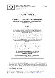
<strong>ETAG</strong> <strong>001</strong> <strong>Part</strong> 3, Page 12Temperature range: 20 to 25°CDuration of test: 100 hours. Following the test, after unloading the screw, an unconfined tension test to failureshall be performed.Test Criteria:During the constant load portion of the test (100 hours), no anchor shall fail. If concrete failure occurs the test shallbe repeated.The failure load of residual load bearing capacity shall be compared to reference tension tests according toreference tests in C50/60. The reduction factor shall fulfil req. α ≥ 0.9.Ca(OH) 2 -sol. (sat.)beveled washerWERECEPOTENTIOSTATreference electrodeh nom0.5 h nomh nomcounter electrode≤ 150mm≤ 50mmconcreteFigure 5.2Test setup (schematic)
<strong>ETAG</strong> <strong>001</strong> <strong>Part</strong> 3, Page 13Table 5.1:Suitability tests for undercut anchors to be used in cracked and non-cracked concretePurpose of testConcreteCrackwidth∆w(mm)Drill bit or diamant corebit d cutMinimum number oftests for anchor size(1) load/displacementbehaviourCriteria Remark Testproceduredescribedinultimateloadreq. α(3)012(a) Setting testsin low strengthconcrete(b) Setting testsin high strengthconcrete(c) Setting testswith impactscrew driverInstallationsafety(a) anchorageintensity(b) contact withreinforcementFunctioning in3 low strengthconcreteFunctioning in4 high strengthconcreteFunctioning in5 crackmovements(a) Functioningunder repeatedloads6 (b) tests withconcrete screwson beveledwashersMaximum torque7momentSensitivity to8brittle fracturefor d 0 for d 1 s i m i lC20/25 0 d cut,max - 10 10 10 10 10 - - (13), (15) 5.1.2.0C50/60 0 d cut,min - 10 10 10 10 10 - - (13) , (15) 5.1.2.0C20/25 0 d cut,max - 15 15 15 15 15 - - (13) 5.1.2.0C20/25(11)C20/25 0.30.3 (7), 5 5 5 5 5 ≥ 0.8 (4) (5), (6)d cut,m,(14)d cut,m,(14)5 5 - - <strong>Part</strong> 1,6.1.1.1≥ 0.7 (4) (2), (6)C20/25 0.5 d cut,max d cut,max 5 5 5 5 ≥ 0.8 (5), (6)C50/60 0.5 d cut,min d cut,min 5 5 5 5 5 ≥ 0.8 (5), (6)C20/25 0.1 - 0.3 d cut,m d cut,m 5 5 5 5 5C20/25 0 d cut,m d cut,m- - 3 - -<strong>Part</strong> 1,6.1.1.1 and6.1.1.2 (a)<strong>Part</strong> 1,6.1.1.1 and6.1.1.2 (b)≥ 0.9 (5), (6)≥ 1.0 (8),Annex A5.2.1Annex A5.8Annex A5.2.1Annex A5.2.1Annex A5.5Annex A5.65 5 5 5 5 ≥ 1.0 (12), (13) 5.1.2.3C50/60 0 d cut,m d cut,m 5 5 5 5 5 - (9) (10)Annex A5.10C50/60 0 d cut,m d cut,m 5 5 5 5 5 ≥ 0.9 (13) 5.1.2.5Notes to Table 5.1(1) Anchor sizes = smallestI = intermediatem = mediuml = largest(2) Necessary only for anchors with h ef < 80 mm to be used in concrete members with a reinforcement ofspacing < 150 mm.(3) α see <strong>Part</strong> 1, Equation (6.2)(4) Valid for γ 2 = 1.2. For other values of γ 2 see <strong>Part</strong> 1, 6.1.2.2.2.(5) If less than three anchor sizes are tested together and/or the different anchor sizes are not similar inrespect of geometry, then the number of tests shall be increased to 10 for all anchor sizes.(6) If the coefficient of variation of the failure loads is v > 10 % or the coefficient of variation of the anchor