- Page 1 and 2: Browse»Search»
- Page 3 and 4: Restek InternationalYour Global Sou
- Page 5 and 6: Restek WorldwideVisit www.restek.co
- Page 7 and 8: Returns & WarrantyimportantnoteIf y
- Page 9 and 10: GC Accessories• Restek Electronic
- Page 11 and 12: Air Monitoring• Vacuum Gauge, pag
- Page 13 and 14: Meet the new companyyou’ve known
- Page 15 and 16: SilcoTek TreatmentsSilcoTek can tre
- Page 18 and 19: GC ColumnsDetailed Table of Content
- Page 20 and 21: Polycyclic Aromatic Hydrocarbons (P
- Page 22 and 23: GC COLUMNS | CAPILLARY COLUMNSSelec
- Page 24 and 25: GC COLUMNS | CAPILLARY COLUMNSSelec
- Page 26 and 27: What Are the Operating Temperatures
- Page 30 and 31: Guard Columns and Retention GapsGua
- Page 32 and 33: GC COLUMNS | CAPILLARY COLUMNSGuard
- Page 34 and 35: GC COLUMNS | CAPILLARY COLUMNSGuard
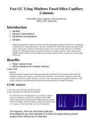
- Page 36 and 37: GC COLUMNS | CAPILLARY COLUMNSFast
- Page 38 and 39: GC COLUMNS | HIGH-PERFORMANCE RXI C
- Page 40 and 41: Column-to-Column ReproducibilityCol
- Page 42 and 43: Rxi®-5ms (low polarity phase, Cros
- Page 44 and 45: Semivolatile organics for US EPA Me
- Page 46 and 47: GC COLUMNS | HIGH-PERFORMANCE RXI C
- Page 48 and 49: GC COLUMNS | GENERAL PURPOSE COLUMN
- Page 50 and 51: GC COLUMNS | GENERAL PURPOSE COLUMN
- Page 52 and 53: GC COLUMNS | GENERAL PURPOSE COLUMN
- Page 54 and 55: GC COLUMNS | GENERAL PURPOSE COLUMN
- Page 56 and 57: Rt®-2330 (highly polar phase; 90%
- Page 58 and 59: Stabilwax® (polar phase; Crossbond
- Page 60 and 61: Basic Compounds AnalysisRtx®-5 Ami
- Page 62 and 63: Basic Compounds AnalysisStabilwax®
- Page 64 and 65: Enantiomers AnalysisCyclodextrin Co
- Page 66 and 67: Polyunsaturated FAME AnalysisFAMEWA
- Page 68 and 69: Triglycerides in Foods AnalysisRtx
- Page 70 and 71: Simulated Distillation (C5-C44) Ana
- Page 72 and 73: Aromatics & Oxygenates in Gasoline
- Page 74 and 75: Blood Alcohol AnalysisRtx®-BAC1/Rt
- Page 76 and 77: Organic Volatile Impurities (OVI) A
- Page 78 and 79:
Organic Volatile Impurities (OVI) A
- Page 80 and 81:
Organophosphorus Pesticides Analysi
- Page 82 and 83:
Chlorinated Pesticides AnalysisGC C
- Page 84 and 85:
Brominated Flame Retardants Analysi
- Page 86 and 87:
PCB Congeners AnalysisGC COLUMNS |
- Page 88 and 89:
Dioxin & Furan Congeners AnalysisRt
- Page 90 and 91:
Polycyclic Aromatic Hydrocarbon (PA
- Page 92 and 93:
Volatile Organics AnalysisRtx®-VRX
- Page 94 and 95:
Volatile Organics AnalysisRtx®-624
- Page 96 and 97:
Features & Benefits of Restek PLOT
- Page 98 and 99:
GC COLUMNS | PLOT COLUMNSPLOT Colum
- Page 100 and 101:
GC COLUMNS | PLOT COLUMNSMolecular
- Page 102 and 103:
GC COLUMNS | PLOT COLUMNSPorous Pol
- Page 104 and 105:
What is an MXT® column?MXT® colum
- Page 106 and 107:
Restek Tubing Scorer for MXT® Colu
- Page 108 and 109:
GC COLUMNS | METAL (MXT®) COLUMNSM
- Page 110 and 111:
GC COLUMNS | METAL (MXT®) COLUMNSM
- Page 112 and 113:
MXT®-502.2 (proprietary Crossbond
- Page 114 and 115:
Bonded Stationary PhasesWe combined
- Page 116 and 117:
GC COLUMNS | PACKED/MICROPACKED COL
- Page 118 and 119:
GC COLUMNS | PACKED/MICROPACKED COL
- Page 120 and 121:
Light Hydrocarbon AnalysisSpecial C
- Page 122 and 123:
Sulfur AnalysisRt®-XLSulfur Packed
- Page 124 and 125:
Packed Column Inlet Adaptor Kits•
- Page 126 and 127:
Res-Sil C Packings• Unique separa
- Page 128 and 129:
Chromosorb® Century PackingsTemp.
- Page 130 and 131:
GC COLUMNS | PACKED/MICROPACKED COL
- Page 132 and 133:
Custom Packed ColumnsTo order, cont
- Page 134:
GC COLUMNS | PACKED/MICROPACKED COL
- Page 137 and 138:
GC ACCESSORIESINSTRUMENTSUPPLIESLea
- Page 139 and 140:
GC ACCESSORIES | INSTRUMENT SUPPLIE
- Page 141 and 142:
GC ACCESSORIES | INSTRUMENT SUPPLIE
- Page 143 and 144:
GC ACCESSORIES | INSTRUMENT SUPPLIE
- Page 145 and 146:
GC ACCESSORIES | INSTRUMENT SUPPLIE
- Page 147 and 148:
GC ACCESSORIES | INSTRUMENT SUPPLIE
- Page 149 and 150:
GC ACCESSORIES | INSTRUMENT SUPPLIE
- Page 151 and 152:
GC ACCESSORIES | INSTRUMENT SUPPLIE
- Page 153 and 154:
GC ACCESSORIES | INSTRUMENT SUPPLIE
- Page 155 and 156:
GC ACCESSORIES | INSTRUMENT SUPPLIE
- Page 157 and 158:
GC ACCESSORIES | INSTRUMENT SUPPLIE
- Page 159 and 160:
GC ACCESSORIES | INSTRUMENT SUPPLIE
- Page 161 and 162:
GC ACCESSORIES | INSTRUMENT SUPPLIE
- Page 163 and 164:
GC ACCESSORIES | INSTRUMENT SUPPLIE
- Page 165 and 166:
GC ACCESSORIES | INSTRUMENT SUPPLIE
- Page 167 and 168:
GC ACCESSORIES | INSTRUMENT SUPPLIE
- Page 169 and 170:
GC ACCESSORIES | INSTRUMENT SUPPLIE
- Page 171 and 172:
GC ACCESSORIES | INSTRUMENT SUPPLIE
- Page 173 and 174:
GC ACCESSORIES | INSTRUMENT SUPPLIE
- Page 175 and 176:
GC ACCESSORIES | INSTRUMENT SUPPLIE
- Page 177 and 178:
GC ACCESSORIES | INSTRUMENT SUPPLIE
- Page 179 and 180:
GC ACCESSORIES | INSTRUMENT SUPPLIE
- Page 181 and 182:
GC ACCESSORIES | INSTRUMENT SUPPLIE
- Page 183 and 184:
GC ACCESSORIES | INSTRUMENT SUPPLIE
- Page 185 and 186:
GC ACCESSORIES | INSTRUMENT SUPPLIE
- Page 187 and 188:
GC ACCESSORIES | INSTRUMENT SUPPLIE
- Page 189 and 190:
GC ACCESSORIES | INSTRUMENT SUPPLIE
- Page 191 and 192:
GC ACCESSORIES | INSTRUMENT SUPPLIE
- Page 193 and 194:
GC ACCESSORIES | INSTRUMENT SUPPLIE
- Page 195 and 196:
GC ACCESSORIES | INSTRUMENT SUPPLIE
- Page 197 and 198:
GC ACCESSORIES | INSTRUMENT SUPPLIE
- Page 199 and 200:
GC ACCESSORIES | INSTRUMENT SUPPLIE
- Page 201 and 202:
GC ACCESSORIESCOLUMNINSTALLATIONLea
- Page 203 and 204:
GC ACCESSORIES | COLUMN INSTALLATIO
- Page 205 and 206:
GC ACCESSORIES | COLUMN INSTALLATIO
- Page 207 and 208:
GC ACCESSORIES | COLUMN INSTALLATIO
- Page 209 and 210:
GC ACCESSORIES | COLUMN INSTALLATIO
- Page 211 and 212:
GC ACCESSORIES | COLUMN INSTALLATIO
- Page 213 and 214:
GC ACCESSORIES | COLUMN INSTALLATIO
- Page 215 and 216:
GC ACCESSORIES | COLUMN INSTALLATIO
- Page 217 and 218:
GC ACCESSORIES | COLUMN INSTALLATIO
- Page 219 and 220:
GC ACCESSORIES | COLUMN INSTALLATIO
- Page 221 and 222:
GC ACCESSORIESGASPURIFICATIONESSENT
- Page 223 and 224:
GC ACCESSORIES | GAS PURIFICATION E
- Page 225 and 226:
GC ACCESSORIES | GAS PURIFICATION E
- Page 227 and 228:
GC ACCESSORIES | GAS PURIFICATION E
- Page 229 and 230:
GC ACCESSORIES | GAS PURIFICATION E
- Page 231 and 232:
GC ACCESSORIES | GAS PURIFICATION E
- Page 233 and 234:
GC ACCESSORIES | GAS PURIFICATION E
- Page 235 and 236:
GC ACCESSORIES | GAS PURIFICATION E
- Page 237 and 238:
GC ACCESSORIES | GAS PURIFICATION E
- Page 239 and 240:
GC ACCESSORIES | GAS PURIFICATION E
- Page 241 and 242:
GC ACCESSORIES | GAS PURIFICATION E
- Page 243 and 244:
GC ACCESSORIES | GAS PURIFICATION E
- Page 245 and 246:
GC ACCESSORIES | GAS PURIFICATION E
- Page 247 and 248:
GC ACCESSORIES | GAS PURIFICATION E
- Page 249 and 250:
GC ACCESSORIES | GAS PURIFICATION E
- Page 252 and 253:
Vials & SyringesVialsOverview . . .
- Page 254 and 255:
Siltek Coated VialsFor a highly ine
- Page 256 and 257:
VIALS & SYRINGES | VIALSVial Size Q
- Page 258 and 259:
2.0mL, 11mm Poly Crimp Seal Caps: S
- Page 260 and 261:
2.0mL Screw-Thread Vials, 12 x 32mm
- Page 262 and 263:
Preassembled Vial Kits and Limited
- Page 264 and 265:
Crimp-Top and Screw-Top Headspace V
- Page 266 and 267:
2.0mL Sample Vial Racks• Racks fe
- Page 268 and 269:
VIALS & SYRINGES | VIALSVial Access
- Page 270 and 271:
Syringe BasicsNeedle Gauge ChartGau
- Page 272 and 273:
Gas-Tight Teflon®-Tipped Syringes
- Page 274 and 275:
Autosampler Syringes for PerkinElme
- Page 276 and 277:
Autosampler Syringes for Shimadzu G
- Page 278 and 279:
Autosampler Syringes for CTC/LEAP G
- Page 280 and 281:
VIALS & SYRINGES | SYRINGESMicrolit
- Page 282 and 283:
VIALS & SYRINGES | SYRINGESGas-Tigh
- Page 284 and 285:
VIALS & SYRINGES | SYRINGESGas-Tigh
- Page 286 and 287:
VIALS & SYRINGES | SYRINGESHPLC Syr
- Page 288 and 289:
VIALS & SYRINGES | SYRINGESHPLC Syr
- Page 290:
VIALS & SYRINGES | SYRINGESHPLC Syr
- Page 293 and 294:
HPLC COLUMNSColumn Selectionorderin
- Page 295 and 296:
HPLC COLUMNSPhysical Characteristic
- Page 297 and 298:
HPLC COLUMNSPhysical Characteristic
- Page 299 and 300:
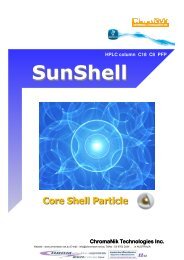
HPLC COLUMNSUHPLC Columnsfreelitera
- Page 301 and 302:
HPLC COLUMNSCapillary HPLC ColumnsR
- Page 303 and 304:
HPLC COLUMNSPinnacle® DB ColumnsPi
- Page 305 and 306:
HPLC COLUMNSPinnacle® DB Columnsfo
- Page 307 and 308:
HPLC COLUMNSPinnacle® II ColumnsPi
- Page 309 and 310:
HPLC COLUMNSPinnacle® II ColumnsAp
- Page 311 and 312:
HPLC COLUMNSAllure® ColumnsAllure
- Page 313 and 314:
HPLC COLUMNSAllure® ColumnsApplica
- Page 315 and 316:
HPLC COLUMNSUltra ColumnsApplicatio
- Page 317 and 318:
HPLC COLUMNSUltra Columnslooking fo
- Page 319 and 320:
HPLC COLUMNSUltra Columnslooking fo
- Page 321 and 322:
HPLC COLUMNSUltra Columnsrestek exc
- Page 323 and 324:
HPLC COLUMNSViva Wide Pore Columnsf
- Page 325 and 326:
HPLC COLUMNSPrep ColumnsHPLC Prep C
- Page 327 and 328:
HPLC COLUMNSBulk Packing MaterialsB
- Page 329 and 330:
HPLC COLUMNSGuard Cartridge Systems
- Page 332 and 333:
HPLCAccessoriesInstrument Replaceme
- Page 334 and 335:
Outlet Cap and Gold Seal Assembly T
- Page 336 and 337:
Restek Replacement Parts for Thermo
- Page 338 and 339:
HPLC ACCESSORIESValvesASI Piston Se
- Page 340 and 341:
HPLC ACCESSORIESFiltersMobile Phase
- Page 342 and 343:
HPLC ACCESSORIESMobile Phase Access
- Page 344 and 345:
HPLC ACCESSORIESColumn Heaters, Gas
- Page 346 and 347:
HPLC ACCESSORIESFittings, Connector
- Page 348 and 349:
HPLC ACCESSORIESConnectors, Tubing
- Page 350 and 351:
HPLC ACCESSORIESFlow Splitters, Sta
- Page 352 and 353:
HPLC ACCESSORIESColumn HardwareHPLC
- Page 354:
HPLC Pump Pressure Conversion Table
- Page 357 and 358:
SAMPLE PREPARATIONSPE CartridgesRes
- Page 359 and 360:
SAMPLE PREPARATIONSPE CartridgesMet
- Page 361 and 362:
SAMPLE PREPARATIONBulk AdsorbentsSo
- Page 363 and 364:
SAMPLE PREPARATIONManifolds, Vacuum
- Page 365 and 366:
SAMPLE PREPARATIONParts for ASE® S
- Page 367 and 368:
SAMPLE PREPARATIONParts for ASE® S
- Page 370 and 371:
Air MonitoringSilcoCan Canisters .
- Page 372 and 373:
AIR MONITORINGCanisters & Carrying
- Page 374 and 375:
AIR MONITORINGCanister Maintenance/
- Page 376 and 377:
AIR MONITORINGCanister SuppliesCani
- Page 378 and 379:
Buy only the parts you need!Replace
- Page 380 and 381:
Miniature Air Sampling Kits• Prov
- Page 382 and 383:
AIR MONITORINGThermal Desorption Un
- Page 384 and 385:
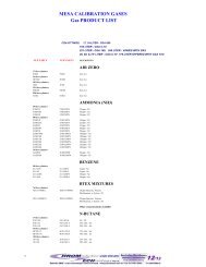
AIR MONITORINGGas StandardsEnvironm
- Page 386 and 387:
AIR MONITORINGGas StandardsTO-14A/T
- Page 388 and 389:
AIR MONITORINGGas StandardsNatural
- Page 390 and 391:
AIR MONITORINGGas Standards, Regula
- Page 392:
Sulfinert® Treated Rupture Disc Te
- Page 395 and 396:
394 www.restek.comANALYTICAL REFERE
- Page 397 and 398:
396 www.restek.comANALYTICAL REFERE
- Page 399 and 400:
ANALYTICALREFERENCEMATERIALSNEAT &
- Page 401 and 402:
ANALYTICAL REFERENCE MATERIALSNeat
- Page 403 and 404:
ANALYTICAL REFERENCE MATERIALSNeat
- Page 405 and 406:
ANALYTICAL REFERENCE MATERIALSNeat
- Page 407 and 408:
ANALYTICALREFERENCEMATERIALSENVIRON
- Page 409 and 410:
ANALYTICAL REFERENCE MATERIALS | EN
- Page 411 and 412:
ANALYTICAL REFERENCE MATERIALS | EN
- Page 413 and 414:
ANALYTICAL REFERENCE MATERIALS | EN
- Page 415 and 416:
ANALYTICAL REFERENCE MATERIALS | EN
- Page 417 and 418:
ANALYTICAL REFERENCE MATERIALS | EN
- Page 419 and 420:
ANALYTICAL REFERENCE MATERIALS | EN
- Page 421 and 422:
ANALYTICAL REFERENCE MATERIALS | EN
- Page 423 and 424:
ANALYTICAL REFERENCE MATERIALS | EN
- Page 425 and 426:
ANALYTICAL REFERENCE MATERIALS | EN
- Page 427 and 428:
ANALYTICAL REFERENCE MATERIALS | EN
- Page 429 and 430:
ANALYTICAL REFERENCE MATERIALS | EN
- Page 431 and 432:
ANALYTICAL REFERENCE MATERIALS | EN
- Page 433 and 434:
ANALYTICAL REFERENCE MATERIALS | EN
- Page 435 and 436:
ANALYTICAL REFERENCE MATERIALS | EN
- Page 437 and 438:
ANALYTICAL REFERENCE MATERIALS | EN
- Page 439 and 440:
ANALYTICAL REFERENCE MATERIALS | EN
- Page 441 and 442:
ANALYTICAL REFERENCE MATERIALS | EN
- Page 443 and 444:
ANALYTICAL REFERENCE MATERIALS | EN
- Page 445 and 446:
ANALYTICAL REFERENCE MATERIALS | EN
- Page 447 and 448:
ANALYTICAL REFERENCE MATERIALS | EN
- Page 449 and 450:
ANALYTICAL REFERENCE MATERIALS | EN
- Page 451 and 452:
ANALYTICAL REFERENCE MATERIALS | EN
- Page 453 and 454:
ANALYTICAL REFERENCE MATERIALS | EN
- Page 455 and 456:
ANALYTICAL REFERENCE MATERIALS | EN
- Page 457 and 458:
ANALYTICAL REFERENCE MATERIALS | EN
- Page 459 and 460:
ANALYTICAL REFERENCE MATERIALS | EN
- Page 461 and 462:
ANALYTICAL REFERENCE MATERIALS | EN
- Page 463 and 464:
ANALYTICAL REFERENCE MATERIALS | EN
- Page 465 and 466:
ANALYTICAL REFERENCE MATERIALS | EN
- Page 467 and 468:
ANALYTICAL REFERENCE MATERIALS | EN
- Page 469 and 470:
ANALYTICALREFERENCEMATERIALSOTHERMA
- Page 471 and 472:
ANALYTICAL REFERENCE MATERIALS | OT
- Page 473 and 474:
ANALYTICAL REFERENCE MATERIALS | OT
- Page 475 and 476:
ANALYTICAL REFERENCE MATERIALS | OT
- Page 477 and 478:
ANALYTICAL REFERENCE MATERIALS | OT
- Page 479 and 480:
ANALYTICAL REFERENCE MATERIALS | OT
- Page 481 and 482:
ANALYTICAL REFERENCE MATERIALS | OT
- Page 483 and 484:
ANALYTICAL REFERENCE MATERIALS | OT
- Page 485 and 486:
ANALYTICAL REFERENCE MATERIALS | OT
- Page 487 and 488:
ANALYTICAL REFERENCE MATERIALS | OT
- Page 490 and 491:
GC/HPLC ApplicationsHPLC Applicatio
- Page 492 and 493:
HPLC APPLICATIONSHPLC Applications
- Page 494 and 495:
HPLC APPLICATIONS | BIOCHEMICAL/CLI
- Page 496 and 497:
Protein Mix on Viva C18Viva C18(cat
- Page 498 and 499:
Cocaine and Ecgonine Methyl Ester o
- Page 500 and 501:
HPLC APPLICATIONS | FORENSICSystem
- Page 502 and 503:
Explosives by EPA Method 8330B on U
- Page 504 and 505:
HPLC APPLICATIONS | ENVIRONMENTALHe
- Page 506 and 507:
HPLC APPLICATIONS | ENVIRONMENTALHe
- Page 508 and 509:
HPLC APPLICATIONS | ENVIRONMENTALPe
- Page 510 and 511:
HPLC APPLICATIONS | ENVIRONMENTALPo
- Page 512 and 513:
HPLC APPLICATIONS | FOODS & FLAVORS
- Page 514 and 515:
HPLC APPLICATIONS | FOODS & FLAVORS
- Page 516 and 517:
HPLC APPLICATIONS | FOODS & FLAVORS
- Page 518 and 519:
HPLC APPLICATIONS | FOODS & FLAVORS
- Page 520 and 521:
HPLC APPLICATIONS | PHARMACEUTICALA
- Page 522 and 523:
Digitalis Extracts/Derivatives on U
- Page 524 and 525:
HPLC APPLICATIONS | PHARMACEUTICALA
- Page 526 and 527:
HPLC APPLICATIONS | PHARMACEUTICALA
- Page 528 and 529:
Antibiotic Cephaloridine on Ultra I
- Page 530 and 531:
HPLC APPLICATIONS | PHARMACEUTICALC
- Page 532 and 533:
Non-Steroidal Anti-inflammatory Dru
- Page 534 and 535:
HPLC APPLICATIONS | PHARMACEUTICALA
- Page 536 and 537:
GC APPLICATIONSGC Applications by C
- Page 538 and 539:
Choosing a Volatiles GC Column for
- Page 540 and 541:
GC APPLICATIONS | ENVIRONMENTALVola
- Page 542 and 543:
GC APPLICATIONS | ENVIRONMENTALVola
- Page 544 and 545:
GC APPLICATIONS | ENVIRONMENTALVola
- Page 546 and 547:
GC APPLICATIONS | ENVIRONMENTALVola
- Page 548 and 549:
GC APPLICATIONS | ENVIRONMENTALSemi
- Page 550 and 551:
GC APPLICATIONS | ENVIRONMENTALSemi
- Page 552 and 553:
GC APPLICATIONS | ENVIRONMENTALSemi
- Page 554 and 555:
GC APPLICATIONS | ENVIRONMENTALSemi
- Page 556 and 557:
GC APPLICATIONS | ENVIRONMENTALSemi
- Page 558 and 559:
GC APPLICATIONS | ENVIRONMENTALSemi
- Page 560 and 561:
Rxi ® -5Sil MSExceptionally Inert
- Page 562 and 563:
GC APPLICATIONS | ENVIRONMENTALSemi
- Page 564 and 565:
GC APPLICATIONS | ENVIRONMENTALSemi
- Page 566 and 567:
Semivolatile OrganicsCLP MethodRtx
- Page 568 and 569:
GC APPLICATIONS | ENVIRONMENTALPest
- Page 570 and 571:
GC APPLICATIONS | ENVIRONMENTALPest
- Page 572 and 573:
GC APPLICATIONS | ENVIRONMENTALPest
- Page 574 and 575:
GC APPLICATIONS | ENVIRONMENTALPest
- Page 576 and 577:
GC APPLICATIONS | ENVIRONMENTALPest
- Page 578 and 579:
GC APPLICATIONS | ENVIRONMENTALPest
- Page 580 and 581:
GC APPLICATIONS | ENVIRONMENTALHerb
- Page 582 and 583:
GC APPLICATIONS | ENVIRONMENTALHerb
- Page 584 and 585:
Aroclor 1242 PCBsRtx®-PCBAroclor 1
- Page 586 and 587:
GC APPLICATIONS | ENVIRONMENTALPCB
- Page 588 and 589:
Aroclor PCBs (Quick Screening)Rtx®
- Page 590 and 591:
GC APPLICATIONS | ENVIRONMENTALBrom
- Page 592 and 593:
GC APPLICATIONS | ENVIRONMENTALChlo
- Page 594 and 595:
Endocrine Disruptors: Alkyl Phenols
- Page 596 and 597:
GC APPLICATIONS | ENVIRONMENTALExpl
- Page 598 and 599:
Texas UST: Alternate Boiling Point/
- Page 600 and 601:
Petroleum Hydrocarbons (TPH)Rxi®-1
- Page 602 and 603:
GC APPLICATIONS | ENVIRONMENTALDies
- Page 604 and 605:
GC APPLICATIONS | ENVIRONMENTALGlyc
- Page 606 and 607:
Haloacetic Acids & DalaponUS EPA Me
- Page 608 and 609:
GC APPLICATIONS | ENVIRONMENTALAirU
- Page 610 and 611:
GC APPLICATIONS | ENVIRONMENTALAirU
- Page 612 and 613:
GC APPLICATIONS | ENVIRONMENTALAirM
- Page 614 and 615:
GC APPLICATIONS | FOODS, FLAVORS, &
- Page 616 and 617:
Commercial Peppermint OilRt®-γDEX
- Page 618 and 619:
Raspberry Flavor - Rt®-βDEXsaGC A
- Page 620 and 621:
Fatty Acids (Free)Stabilwax®-DAGC
- Page 622 and 623:
GC APPLICATIONS | FOODS, FLAVORS, &
- Page 624 and 625:
GC APPLICATIONS | FOODS, FLAVORS, &
- Page 626 and 627:
GC APPLICATIONS | FOODS, FLAVORS, &
- Page 628 and 629:
Bergamot OilFast GC/MSRtx®-5GC APP
- Page 630 and 631:
GC APPLICATIONS | FOODS, FLAVORS, &
- Page 632 and 633:
GC APPLICATIONS | FOODS, FLAVORS, &
- Page 634 and 635:
GC APPLICATIONS | FOODS, FLAVORS, &
- Page 636 and 637:
GC APPLICATIONS | FOODS, FLAVORS, &
- Page 638 and 639:
Flavor & Fragrance CompoundsRt®-CW
- Page 640 and 641:
GC APPLICATIONS | FOODS, FLAVORS, &
- Page 642 and 643:
Organochlorine and Organophosphorus
- Page 644 and 645:
Egg Pasta: Sterols & GlyceridesRtx
- Page 646 and 647:
Cleaning SolventsRtx®-Wax1. methan
- Page 648 and 649:
GC APPLICATIONS | PETROLEUM & PETRO
- Page 650 and 651:
GC APPLICATIONS | PETROLEUM & PETRO
- Page 652 and 653:
Permanent GasesRt®-Msieve 5A(PLOT)
- Page 654 and 655:
Hydrocarbon GasesRt®-QPLOT(PLOT)1.
- Page 656 and 657:
GC APPLICATIONS | PETROLEUM & PETRO
- Page 658 and 659:
GC APPLICATIONS | PETROLEUM & PETRO
- Page 660 and 661:
Motor Oil & Aviation GasASTM Method
- Page 662 and 663:
GC APPLICATIONS | PETROLEUM & PETRO
- Page 664 and 665:
Simulated Distillation(Standard Cal
- Page 666 and 667:
Simulated Distillation (ASTM D-3710
- Page 668 and 669:
Unleaded GasolineRxi®-1msNEW!99% W
- Page 670 and 671:
Blood AlcoholRtx®-BAC1 & Rtx®-BAC
- Page 672 and 673:
GC APPLICATIONS | FORENSICGHB/GBLγ
- Page 674 and 675:
GC APPLICATIONS | FORENSICAlkyl Nit
- Page 676 and 677:
Cocaine & Cocaine AdulterantsRtx®-
- Page 678 and 679:
AmphetaminesRtx®-5MSGC APPLICATION
- Page 680 and 681:
Sympathomimetic Amines (Basic Drugs
- Page 682 and 683:
Barbiturates (Acidic/Neutral Drugs)
- Page 684 and 685:
Basic Drugs (Underivatized )Rtx®-5
- Page 686 and 687:
Cold Medications (Basic Drugs) (Und
- Page 688 and 689:
Ibuprofen (Underivatized)Rt®-βDEX
- Page 690 and 691:
GC APPLICATIONS | PHARMACEUTICALBas
- Page 692 and 693:
GC APPLICATIONS | PHARMACEUTICALOrg
- Page 694 and 695:
Residual Solvents Class 2 Mixture B
- Page 696 and 697:
Residual Solvents Class 2Stabilwax
- Page 698 and 699:
Residual SolventsEuropean Pharmacop
- Page 700 and 701:
SolventsRt®-QS-BOND1. methanol2. a
- Page 702 and 703:
Hexamethylenediamine (HMD)Stabilwax
- Page 704 and 705:
Freon® 12 & Ethylene OxideRtx®-11
- Page 706 and 707:
INDEXApplications by Compound Class
- Page 708 and 709:
www.restek.com 707INDEXCompound Ind
- Page 710 and 711:
www.restek.com 709INDEXCompound Ind
- Page 712 and 713:
www.restek.com 711INDEXCompound Ind
- Page 714 and 715:
www.restek.com 713INDEXCompound Ind
- Page 716 and 717:
INDEXCompound Index for GC Applicat