Solenoid Operated Micro-Pumps
Solenoid Operated Micro-Pumps
Solenoid Operated Micro-Pumps
- No tags were found...

You also want an ePaper? Increase the reach of your titles
YUMPU automatically turns print PDFs into web optimized ePapers that Google loves.
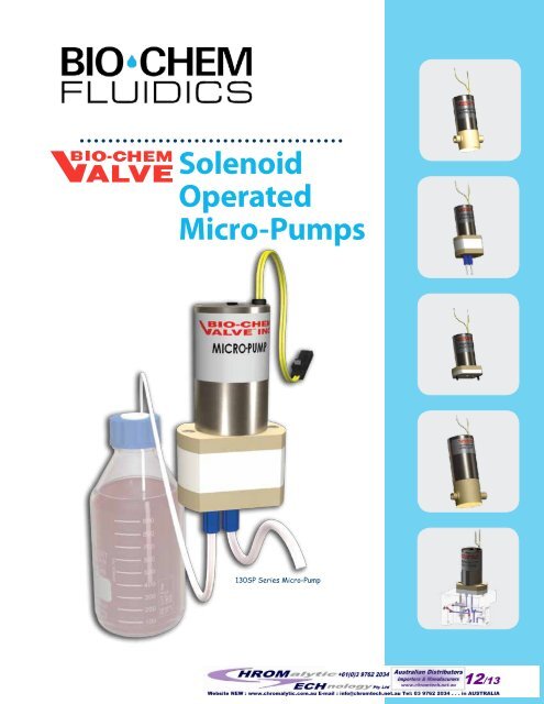
<strong>Solenoid</strong><br />
<strong>Operated</strong><br />
<strong>Micro</strong>-<strong>Pumps</strong><br />
130SP Series <strong>Micro</strong>-Pump
2<br />
Index<br />
Page 3<br />
Page 4<br />
Page 5<br />
<strong>Micro</strong>-Pump Selection Guide<br />
<strong>Micro</strong>-Pump Applications<br />
Waste effluent removal, chemcial dosing, pumping of sterlizing solution<br />
120SP Series <strong>Micro</strong>-Pump<br />
Ported <strong>Micro</strong>-<strong>Pumps</strong> (1/4”-28 UNF) for precise dispense volumes from 10 to 60µl<br />
Page 7<br />
130SP Series <strong>Micro</strong>-Pump<br />
Ported <strong>Micro</strong>-<strong>Pumps</strong> (1/4”-28 UNF) for precise dispense volumes from 10 to 60µl (inert body)<br />
Page 9<br />
Page 11<br />
Page 13<br />
Page 14<br />
150SP Series <strong>Micro</strong>-Pump<br />
Ported <strong>Micro</strong>-<strong>Pumps</strong> (5/16”-24 UNF) for precise dispense volumes from 100 to 250µl<br />
139SP Series <strong>Micro</strong>-Pump<br />
Manifold mounted <strong>Micro</strong>-<strong>Pumps</strong> for precise dispense volumes from 10 to 60µl<br />
Manifolds and Mounting Options<br />
<strong>Micro</strong>-<strong>Pumps</strong> Tech Tips - operation and installation<br />
micro-pumps general inforMATion<br />
What is a <strong>Micro</strong>-Pump<br />
A <strong>Micro</strong>-Pump is a solenoid operated device designed to provide<br />
a precise, repeatable and discrete dispensed volume of fluid. The<br />
Fluid outlet<br />
Check valve<br />
element B<br />
Spring<br />
<strong>Solenoid</strong><br />
Check valve<br />
element A<br />
Diaphragm<br />
Fluid inlet<br />
flow path is<br />
isolated from<br />
the operating<br />
mechanism<br />
by a flexible<br />
diaphragm. When<br />
the solenoid is<br />
energized, the<br />
diaphragm is<br />
retracted creating<br />
a partial vacuum<br />
within the pump<br />
body. This pulls<br />
liquid through<br />
the inlet check<br />
valve (A) and<br />
simultaneously<br />
closes the outlet<br />
check valve<br />
(B). When the<br />
solenoid is de-energized a spring pushes the diaphragm down,<br />
expelling a discrete volume of liquid through check valve B while<br />
simultaneously closing check valve A. <strong>Micro</strong>-<strong>Pumps</strong> require a<br />
complete on-off cycle for each discrete dispense. Repeatedly cycling<br />
the solenoid creates a pulsed flow (refer to “Accurate discrete dispense volumes”<br />
in next column).<br />
Features of the Bio-Chem Valve <strong>Micro</strong>-Pump<br />
Inert materials<br />
Our pumps provide a non-metallic inert fluid path for the<br />
dispensing of high purity or aggressive fluids. There is a range of<br />
different materials available for all the wetted parts of the pumps<br />
- body, diaphragm and check valve. Material combinations can be<br />
chosen to suit the application (refer to individual product selection pages for<br />
standard combinations - custom combinations are available, refer to page 14).<br />
Body materials: PPS, PTFE, PEEK, POM<br />
Diaphragm materials: EPDM, PTFE<br />
Check valve materials: EPDM, FKM, FFKM<br />
Self-priming<br />
At start-up, pumps are able to draw air. The suction created by the<br />
pumps is sufficient to pull liquids from an unpressurized container<br />
located up to 4’ 3” (1.3m) beneath the pump. Once the pump<br />
is primed, it is able to generate around 5psi (0.3bar) pressure,<br />
equating to 11’ 6” (3.5m) of water.<br />
Continuous duty<br />
The pumps are capable of continuous duty. They are suitable for<br />
up to 20 million actuations, corresponding to nearly 3,000 hours<br />
of continuous use at a 2 Hz cycle rate.<br />
Accurate discrete dispense volumes<br />
Dispense volumes range from 20µl to 250µl per cycle. The pumps<br />
can be cycled at up to 2 Hz for the smallest version and 1.6 Hz for<br />
the largest. <strong>Pumps</strong> can be operated at less than the maximum<br />
cycle rate by increasing the length of the “off” time. The “on” time<br />
should remain unchanged to retain dispense accuracy.<br />
www.biochemfluidics.com
3<br />
<strong>Micro</strong>-Pump Selection Guide<br />
1. Select pump style; either Ported or Manifold mount and work from the appropriate table:<br />
· Ported for direct connection with 1/4”-28 fittings (5/16”-24 for 150SP)<br />
· Manifold mount for use with manifolds (see page 13)<br />
Then:<br />
2. Locate the volumetric characteristics that best suit your needs<br />
3. Choose your preferred body material depending on the level of chemical inertness you require<br />
4. Turn to the pages indicated to see full details and ordering information for each pump.<br />
Ported<br />
Volumetric output<br />
Body Material<br />
Discrete Max flow<br />
Dispense rate (ml/<br />
Vol (µl) min)<br />
PTFE PPS PEEK POM<br />
20 2.4<br />
30 3.6 130SP (pg. 7) 120SP (pg. 5) 120SP (pg. 5) 130SP (pg. 7)<br />
40 4.8<br />
50 6.0<br />
60 7.2<br />
100 9.6<br />
125 12.0<br />
150 14.4<br />
175 16.8 150SP (pg. 9) 150SP (pg. 9)<br />
200 19.2<br />
225 21.6<br />
250 24.0<br />
Manifold mounted<br />
Volumetric output<br />
Discrete Max flow<br />
Dispense rate (ml/<br />
Vol (µl) min)<br />
Body Material<br />
PTFE PPS PEEK POM<br />
20 2.4<br />
30 3.6 139SP (pg. 11) 139SP (pg. 11) 139SP (pg. 11)<br />
40 4.8<br />
50 6.0<br />
60 7.2<br />
Polymers referenced in this brochure:<br />
EPDM = ethylene-propylene-diene<br />
ETFE = ethylene tetrafluoroethylene<br />
FEP = fluorinated ethylene propylene<br />
FKM = fluorinated elastomer<br />
FFKM = perfluoro elastomer<br />
PEEK = polyetheretherketone<br />
POM = polyoxymethylene (Acetal resin)<br />
PPS = polyphenelyne sulfide<br />
PTFE = polytetrafluoroethylene.
4<br />
<strong>Micro</strong>-Pump Applications<br />
Waste effluent removal<br />
Many types of analytical instruments incorporate a waste sump or container that collects any liquids that may have leaked inside the<br />
instrument. These waste streams can have<br />
Level control<br />
many constituents and could be regarded as a<br />
biohazard if allowed to collect in the bottom of<br />
the instrument.<br />
Waste sump<br />
<strong>Micro</strong>-Pump<br />
Waste solvent<br />
container<br />
Bio-Chem Fluidics <strong>Micro</strong>-<strong>Pumps</strong> lend<br />
themselves to this application because they<br />
offer a completely inert flow path capable of<br />
handling the most aggressive of effluents, while<br />
maintaining repeatable and consistent pumping<br />
rates.<br />
A <strong>Micro</strong>-Pump can be hooked up to the level<br />
control sensor and be cycled as necessary to<br />
empty the sump to an external waste solvent<br />
container.<br />
Chemical dosing<br />
In this application Bio-Chem Fluidics <strong>Micro</strong>-<strong>Pumps</strong> are used to<br />
pre-treat a liquid stream prior to analysis. The pumps are capable<br />
of pumping highly aggressive chemical reagents from a remote<br />
location (outside of the instrument) and accurately dispense<br />
predetermined volumes of the reagents directly into the main<br />
liquid stream.<br />
This eliminates the need for an intermediate mixing step inside the<br />
instrument.<br />
<strong>Micro</strong>-<strong>Pumps</strong> can be used in either continuous or intermittent<br />
mode depending on the demands of the instrument.<br />
Aggressive<br />
chemical<br />
reagents<br />
<strong>Micro</strong>-Pump #1<br />
<strong>Micro</strong>-Pump #2<br />
Water stream<br />
Water analyzer<br />
Sterilizing application<br />
Sterilizing solution can be of a very high purity which almost always translates to additional expense. In this application a Bio-Chem Fluidics<br />
<strong>Micro</strong>-Pump takes small amounts of the sterilizing liquid<br />
Sterilizing<br />
liquid<br />
<strong>Micro</strong>-Pump<br />
Heating panel<br />
Sterilizing<br />
box<br />
from a reservoir and dispenses very accurate “drips”<br />
onto a heating panel inside a sterilizing chamber. When<br />
the liquid hits the panel, it instantly vaporizes forming<br />
a “sterilizing vapor” inside the chamber. The vapor is<br />
very efficient at sterilizing the internals of complicated<br />
components.<br />
The <strong>Micro</strong>-<strong>Pumps</strong> provide highly repeatable and<br />
consistent delivery of the sterilizing fluid into the<br />
chamber. This safe and cost effective method of pumping<br />
high purity liquids has proved very successful.<br />
www.biochemfluidics.com
5<br />
120SP Series MICRO-pump<br />
For precise dispensing between 20 and 60µl and<br />
flow rates up to 7.2 ml/min<br />
• Self-priming<br />
• 20-60µl discrete dispense volumes<br />
• Up to 7.2 ml/min maximum flow rate<br />
• 1/4”-28 UNF threaded ports<br />
The 120SP series <strong>Micro</strong>-<strong>Pumps</strong> are solenoid operated, with the<br />
operating mechanism isolated from the flow path by a diaphragm.<br />
Check valves situated at the inlet and outlet of the pump control<br />
the direction of flow. The combination of materials for each<br />
component can be selected to best suit your specific application.<br />
ARRANGEMENT<br />
Lead wires<br />
<strong>Solenoid</strong><br />
Materials available for the wetted parts are:<br />
• Body materials: PPS, PEEK<br />
• Diaphragm materials: PTFE, EPDM<br />
• Check valve materials: EPDM, FKM, FFKM<br />
120SP series options<br />
NOTE: For 24 VDC, replace 120SP12 with 120SP24 in<br />
any of the part numbers listed.<br />
Body<br />
1/4”-28<br />
Inlet &<br />
Outlet ports<br />
PART NO.<br />
Dispense<br />
Vol (μl)<br />
body<br />
Material<br />
diaphragm<br />
MATerial<br />
check VAlve<br />
MATerial<br />
PART NO.<br />
Dispense<br />
Vol (μl)<br />
body<br />
Material<br />
diaphragm<br />
MATerial<br />
check VAlve<br />
MATerial<br />
12 VDC; 20µl dispense<br />
120SP1220-4EE 20 PPS EPDM EPDM<br />
120SP1220-4TV 20 PPS PTFE FKM<br />
120SP1220-4TP 20 PPS PTFE FFKM<br />
120SP1220-5EE 20 PEEK EPDM EPDM<br />
120SP1220-5TV 20 PEEK PTFE FKM<br />
120SP1220-5TP 20 PEEK PTFE FFKM<br />
12 VDC; 30µl dispense<br />
120SP1230-4EE 30 PPS EPDM EPDM<br />
120SP1230-4TV 30 PPS PTFE FKM<br />
120SP1230-4TP 30 PPS PTFE FFKM<br />
120SP1230-5EE 30 PEEK EPDM EPDM<br />
120SP1230-5TV 30 PEEK PTFE FKM<br />
120SP1230-5TP 30 PEEK PTFE FFKM<br />
12 VDC; 40µl dispense<br />
120SP1240-4EE 40 PPS EPDM EPDM<br />
120SP1240-4TV 40 PPS PTFE FKM<br />
120SP1240-4TP 40 PPS PTFE FFKM<br />
120SP1240-5EE 40 PEEK EPDM EPDM<br />
120SP1240-5TV 40 PEEK PTFE FKM<br />
120SP1240-5TP 40 PEEK PTFE FFKM<br />
12 VDC; 50µl dispense<br />
120SP1250-4EE 50 PPS EPDM EPDM<br />
120SP1250-4TV 50 PPS PTFE FKM<br />
120SP1250-4TP 50 PPS PTFE FFKM<br />
120SP1250-5EE 50 PEEK EPDM EPDM<br />
120SP1250-5TV 50 PEEK PTFE FKM<br />
120SP1250-5TP 50 PEEK PTFE FFKM<br />
12 VDC; 60µl dispense (Note: EPDM diaphragm for all 60 µl options)<br />
120SP1260-4EE 60 PPS EPDM EPDM<br />
120SP1260-5EE 60 PEEK EPDM EPDM
6<br />
INSTALLATION DRAWING<br />
1<br />
2 3 4 5 6 7 8<br />
A<br />
Lead wires not to scale<br />
Wires are 26 AWG and min 24” (610mm) long<br />
2x 1/4”-28 UNF<br />
Flat bottom port<br />
Depth of port = .25” min. (6.4mm)<br />
A<br />
B<br />
Ø1.0”<br />
(Ø25.4mm)<br />
.49”<br />
(12.4mm)<br />
Outlet<br />
.72”<br />
(18.3mm)<br />
B<br />
C<br />
D<br />
E<br />
F<br />
Set screw<br />
position<br />
variable<br />
to +.25” (6mm)<br />
(2.5”)<br />
(63.5mm)<br />
.84”<br />
(21.3mm)<br />
.688”<br />
(17.5mm)<br />
2x #4-40 UNF<br />
Mounting holes<br />
Inlet<br />
1.4”<br />
(35.6mm)<br />
<strong>Micro</strong>-Pump<br />
120SP series<br />
C<br />
D<br />
E<br />
F<br />
1 2 3 4 5 6 7 8<br />
SPECIFICATIONS<br />
120SP Fluid Data<br />
Dispense Volume (μl) 20 30 40 50 60<br />
Set-point accuracy +/- 10% +/- 10% +/- 10% +/- 10% +/- 10%<br />
Repeatability +/- 5% +/- 5% +/- 5% +/- 5% +/- 5%<br />
Max flow rate (μl/min) 2400 3600 4800 6000 7200<br />
Internal vol (μl) 105 105 105 105 105<br />
Voltage<br />
Power<br />
@70˚F (21˚C)<br />
120SP Electrical Data<br />
Current<br />
@70˚F (21˚C)<br />
Effective continuous<br />
power @ max cycle rate<br />
12 VDC 4.0 Watts 0.32 amps 1.2 Watts<br />
24 VDC 4.0 Watts 0.16 amps 1.2 Watts<br />
120SP Cycle Rates<br />
Fixed “on” time Min “off” time Max cycle rate<br />
150 msec 350 msec 2.0 Hz<br />
Recommended tubing for 120SP<br />
Inlet & outlet, 1/32” (0.80mm) ID, hardwall<br />
tubing, PART NO. 008T16-080<br />
120SP <strong>Micro</strong>-<strong>Pumps</strong> can be cycled at up to 2 Hz. To maintain<br />
pumping precision the voltage “on” time should remain fixed -<br />
the pumping rate can be changed by increasing the “off” time.<br />
Voltage (v)<br />
a = 150 msec (fixed)<br />
b = 350 msec (minimum, adjustable)<br />
a<br />
b<br />
Time (msec)<br />
www.biochemfluidics.com
7<br />
130SP Series MICRO-pump<br />
For precise dispensing between 20 and 60µl and<br />
flow rates up to 7.2 ml/min<br />
• Self-priming<br />
• 20-60µl discrete dispense volumes<br />
• Up to 7.2 ml/min maximum flow rate<br />
• 1/4”-28 UNF threaded ports<br />
• Most inert body material for harshest applications<br />
The 130SP series <strong>Micro</strong>-<strong>Pumps</strong> are solenoid operated, with the<br />
operating mechanism isolated from the flow path by a diaphragm.<br />
Check valves situated at the inlet and outlet of the pump control the<br />
direction of flow. The combination of materials for each component<br />
can be selected to best suit your specific application.<br />
ARRANGEMENT<br />
Lead wires<br />
<strong>Solenoid</strong><br />
Materials available for the wetted parts are:<br />
• Body materials: PTFE, POM<br />
• Diaphragm materials: PTFE, EPDM<br />
• Check valve materials: EPDM, FKM, FFKM<br />
130SP series options<br />
NOTE: For 24 VDC, replace 130SP12 with 130SP24 in<br />
any of the part numbers listed.<br />
PART NO.<br />
Dispense<br />
Vol (μl)<br />
body<br />
MATerial<br />
diaphrAGM<br />
MATerial<br />
check valve<br />
MATerial<br />
12 VDC; 20µl dispense<br />
130SP1220-1TP 20 PTFE PTFE FFKM<br />
130SP1220-6TV 20 POM PTFE FKM<br />
130SP1220-6EE 20 POM EPDM EPDM<br />
12 VDC; 30µl dispense<br />
130SP1230-1TP 30 PTFE PTFE FFKM<br />
130SP1230-6TV 30 POM PTFE FKM<br />
130SP1230-6EE 30 POM EPDM EPDM<br />
12 VDC; 40µl dispense<br />
130SP1240-1TP 40 PTFE PTFE FFKM<br />
130SP1240-6TV 40 POM PTFE FKM<br />
130SP1240-6EE 40 POM EPDM EPDM<br />
12 VDC; 50µl dispense<br />
130SP1250-1TP 50 PTFE PTFE FFKM<br />
130SP1250-6TV 50 POM PTFE FKM<br />
130SP1250-6EE 50 POM EPDM EPDM<br />
12 VDC; 60µl dispense<br />
130SP1260-6EE 60 POM EPDM EPDM<br />
Body<br />
PEEK support<br />
plates (not<br />
wetted, PTFE<br />
body only)<br />
1/4”-28<br />
Inlet &<br />
Outlet ports<br />
(shown with<br />
Omni-Lok<br />
fittings, see<br />
page 17)
8<br />
INSTALLATION DRAWING<br />
1<br />
2 3 4 5 6 7 8<br />
A<br />
Lead wires not to scale<br />
Wires are 26 AWG and min 24” (610mm) long<br />
A<br />
B<br />
Ø1.0”<br />
(Ø25.4mm)<br />
2x 1/4”-28 UNF<br />
Flat bottom port<br />
Depth of port = .25” min (6.4mm)<br />
B<br />
C<br />
D<br />
E<br />
Set screw<br />
position<br />
variable<br />
to +.25” (6mm)<br />
(2.67”)<br />
(67.8mm)<br />
1.0”<br />
(25.4mm)<br />
1.5”<br />
(38.1mm)<br />
Outlet<br />
Inlet<br />
1.0”<br />
(25.4mm)<br />
A<br />
<strong>Micro</strong>-Pump<br />
130SP series<br />
C<br />
D<br />
E<br />
F<br />
PTFE body POM/PEEK body<br />
Dim A .280”(7.1mm) .345”(8.8mm)<br />
F<br />
1 2 3 4 5 6 7 8<br />
SPECIFICATIONS<br />
130SP Volumetric Data<br />
Dispense Volume (μl) 20 30 40 50 60<br />
Set-point accuracy +/- 10% +/- 10% +/- 10% +/- 10% +/- 10%<br />
Repeatability +/- 5% +/- 5% +/- 5% +/- 5% +/- 5%<br />
Max flow rate (μl/min) 2400 3600 4800 6000 7200<br />
Internal vol (μl) 105 105 105 105 105<br />
Voltage<br />
Power<br />
@70˚F (21˚C)<br />
130SP Electrical Data<br />
Current<br />
@70˚F (21˚C)<br />
Effective continuous<br />
power @ max cycle rate<br />
12 VDC 4.0 Watts 0.32 amps 1.2 Watts<br />
24 VDC 4.0 Watts 0.16 amps 1.2 Watts<br />
130SP Cycle Rates<br />
Fixed “on” time Min “off” time Max cycle rate<br />
150 msec 350 msec 2.0 Hz<br />
Recommended tubing for 130SP<br />
Inlet & outlet, 1/32” (0.80mm) ID, hardwall<br />
tubing, PART NO. 008T16-080<br />
130SP <strong>Micro</strong>-<strong>Pumps</strong> can be cycled at up to 2 Hz. To maintain<br />
pumping precision the voltage “on” time should remain fixed -<br />
the pumping rate can be changed by increasing the “off” time.<br />
Voltage (v)<br />
a = 150 msec (fixed)<br />
b = 350 msec (minimum, adjustable)<br />
a<br />
b<br />
Time (msec)<br />
www.biochemfluidics.com
9<br />
150SP Series mICRO-pump<br />
For precise dispensing between 100 and 250µl and<br />
flow rates up to 24 ml/min<br />
ARRANGEMENT<br />
• Self-priming<br />
• 100-250µl discrete dispense volumes<br />
• Up to 24 ml/min maximum flow rate<br />
• 5/16”-24 UNF threaded ports<br />
The 150SP series <strong>Micro</strong>-<strong>Pumps</strong> are solenoid operated, with the<br />
operating mechanism isolated from the flow path by a diaphragm.<br />
Check valves situated at the inlet and outlet of the pump control<br />
the direction of flow. The combination of materials for each<br />
component can be selected to best suit your specific application.<br />
Lead wires<br />
<strong>Solenoid</strong><br />
Materials available for the wetted parts are:<br />
• Body materials: PPS, PEEK<br />
• Diaphragm materials: EPDM<br />
• Check valve materials: EPDM<br />
Body<br />
150SP series options<br />
NOTE: For 24 VDC, replace 150SP12 with 150SP24 in<br />
any of the part numbers listed.<br />
PART NO.<br />
Dispense<br />
Vol (μl)<br />
body<br />
MATerial<br />
diaphrAGM<br />
MATerial<br />
check valve<br />
MATerial<br />
12 VDC; 100µl dispense<br />
150SP12100-4EE 100 PPS EPDM EPDM<br />
150SP12100-5EE 100 PEEK EPDM EPDM<br />
12 VDC; 125µl dispense<br />
150SP12125-4EE 125 PPS EPDM EPDM<br />
150SP12125-5EE 125 PEEK EPDM EPDM<br />
12 VDC; 150µl dispense<br />
150SP12150-4EE 150 PPS EPDM EPDM<br />
150SP12150-5EE 150 PEEK EPDM EPDM<br />
5/16”-24<br />
Inlet &<br />
Outlet ports<br />
12 VDC; 175µl dispense<br />
150SP12175-4EE 175 PPS EPDM EPDM<br />
150SP12175-5EE 175 PEEK EPDM EPDM<br />
12 VDC; 200µl dispense<br />
150SP12200-4EE 200 PPS EPDM EPDM<br />
150SP12200-5EE 200 PEEK EPDM EPDM<br />
12 VDC; 225µl dispense<br />
150SP12225-4EE 225 PPS EPDM EPDM<br />
150SP12225-5EE 225 PEEK EPDM EPDM<br />
12 VDC; 250µl dispense<br />
150SP12250-4EE 250 PPS EPDM EPDM<br />
150SP12250-5EE 250 PEEK EPDM EPDM
10<br />
INSTALLATION DRAWING<br />
1<br />
2 3 4 5 6 7 8<br />
A<br />
A<br />
Lead wires not to scale<br />
Wires are 22 AWG and min 15” (381mm) long<br />
B<br />
C<br />
D<br />
E<br />
Set screw<br />
position<br />
variable<br />
to +.25”<br />
(6mm)<br />
Ø1.5”<br />
(Ø38.1mm)<br />
(3.9”)<br />
(99.1mm)<br />
1.35”<br />
(34.3mm)<br />
.51”<br />
(13.0mm)<br />
2x 5/16”-24 UNF<br />
Flat bottom port<br />
Depth of port = .31” (7.9mm)<br />
Outlet<br />
1.13”<br />
(28.7mm)<br />
2x #8-32 UNC<br />
Mounting holes<br />
Inlet<br />
1.13”<br />
(28.7mm)<br />
2.16”<br />
(54.9mm)<br />
<strong>Micro</strong>-Pump<br />
150SP series<br />
B<br />
C<br />
D<br />
E<br />
F<br />
F<br />
1 2 3 4 5 6 7 8<br />
SPECIFICATIONS<br />
150SP Fluid Data<br />
Dispense Volume (μl) 100 125 150 175 200 225 250<br />
Set-point accuracy +/- 10% +/- 10% +/- 10% +/- 10% +/- 10% +/- 10% +/- 10%<br />
Repeatability +/- 5% +/- 5% +/- 5% +/- 5% +/- 5% +/- 5% +/- 5%<br />
Max flow rate (μl/min) 9600 12000 14400 16800 19200 21600 24000<br />
Internal vol (μl) 710 710 710 710 710 710 710<br />
Voltage<br />
Power<br />
@70˚F (21˚C)<br />
150SP Electrical Data<br />
Current<br />
@70˚F (21˚C)<br />
Effective continuous<br />
power @ max cycle rate<br />
12 VDC 8.0 Watts 0.66 amps 3.2 Watts<br />
24 VDC 8.0 Watts 0.33 amps 3.2 Watts<br />
150SP Cycle Rates<br />
Fixed “on” time Min “off” time Max cycle rate<br />
200 msec 400 msec 1.6 Hz<br />
Recommended tubing for 150SP<br />
Inlet & outlet, 1/8” (3.2mm) ID, hardwall tubing,<br />
PART NUMBER 008T47-032<br />
150SP <strong>Micro</strong>-<strong>Pumps</strong> can be cycled at up to 1.6 Hz. To maintain<br />
pumping precision the voltage “on” time should remain fixed -<br />
the pumping rate can be changed by increasing the “off” time.<br />
Voltage (v)<br />
a = 200 msec (fixed)<br />
b = 400 msec (minimum, adjustable)<br />
a<br />
b<br />
Time (msec)<br />
www.biochemfluidics.com
11<br />
139SP Series mICRO-pump<br />
For precise dispensing between 20 and 60µl and<br />
flow rates up to 7.2 ml/min in a manifold mountable design<br />
ARRANGEMENT<br />
• Self-priming<br />
• 20-60µl discrete dispense volumes<br />
• Up to 7.2 ml/min maximum flow rate<br />
• Manifold mountable<br />
This sibling to the 130SP <strong>Micro</strong>-Pump duplicates the performance<br />
characteristics but is supplied ready for mounting in your manifold.<br />
Please contact us if you would like us to supply the manifold (see page<br />
12). Materials available for the wetted parts are:<br />
• Body materials: PTFE, POM, PEEK<br />
• Diaphragm materials: PTFE, EPDM<br />
• Check valve materials: EPDM, FKM, FFKM<br />
139SP series options<br />
NOTE: For 24 VDC, replace 139SP12 with 139SP24 in<br />
any of the part numbers listed.<br />
Lead wires<br />
<strong>Solenoid</strong><br />
Body<br />
PEEK support<br />
plate (not<br />
wetted, PTFE<br />
version only)<br />
Mounting<br />
screws<br />
Locating pin<br />
PART NO.<br />
Dispense<br />
Vol (μl)<br />
body<br />
MATerial<br />
diaphrAGM<br />
MATerial<br />
check valve<br />
MATerial<br />
PART NO.<br />
Dispense<br />
Vol (μl)<br />
body<br />
MATerial<br />
diaphrAGM<br />
MATerial<br />
check valve<br />
MATerial<br />
12 VDC; 20µl dispense<br />
139SP1220-1TP 20 PTFE PTFE FFKM<br />
139SP1220-5TP 20 PEEK PTFE FFKM<br />
139SP1220-5TV 20 PEEK PTFE FKM<br />
139SP1220-5TE 20 PEEK PTFE EPDM<br />
139SP1220-6TV 20 POM PTFE FKM<br />
139SP1220-6EE 20 POM EPDM EPDM<br />
12 VDC; 30µl dispense<br />
139SP1230-1TP 30 PTFE PTFE FFKM<br />
139SP1230-5TP 30 PEEK PTFE FFKM<br />
139SP1230-5TV 30 PEEK PTFE FKM<br />
139SP1230-5TE 30 PEEK PTFE EPDM<br />
139SP1230-6TV 30 POM PTFE FKM<br />
139SP1230-6EE 30 POM EPDM EPDM<br />
12 VDC; 40µl dispense<br />
139SP1240-1TP 40 PTFE PTFE FFKM<br />
139SP1240-5TP 40 PEEK PTFE FFKM<br />
139SP1240-5TV 40 PEEK PTFE FKM<br />
139SP1240-5TE 40 PEEK PTFE EPDM<br />
139SP1240-6TV 40 POM PTFE FKM<br />
139SP1240-6EE 40 POM EPDM EPDM<br />
12 VDC; 50µl dispense<br />
139SP1250-1TP 50 PTFE PTFE FFKM<br />
139SP1250-5TP 50 PEEK PTFE FFKM<br />
139SP1250-5TV 50 PEEK PTFE FKM<br />
139SP1250-5TE 50 PEEK PTFE EPDM<br />
139SP1250-6TV 50 POM PTFE FKM<br />
139SP1250-6EE 50 POM EPDM EPDM<br />
12 VDC; 60µl dispense<br />
139SP1260-6EE 60 POM EPDM EPDM<br />
SPECIFICATIONS<br />
The 139SP has the same specifications as the 130SP (see page 7)
12<br />
INSTALLATION DRAWING<br />
A<br />
B<br />
C<br />
D<br />
E<br />
F<br />
1<br />
2 3 4 5 6 7 8<br />
PTFE body POM/PEEK body<br />
Dim ØA .096”(2.4mm) .125”(3.2mm)<br />
Dim B .50” (12.7mm) .34” (8.6mm)<br />
Dim C .59” (15.0mm) .62” (15.7mm)<br />
Lead wires not to scale<br />
Wires are 26 gauge and min 24” (610mm) long<br />
Ø1.0”<br />
Ø25.4mm<br />
Set screw<br />
position<br />
variable<br />
to +.25” (6mm)<br />
(2.10”)<br />
(53.3mm)<br />
Check valves and<br />
screws included<br />
B<br />
C<br />
Outlet<br />
ØA<br />
Locating pin<br />
Inlet<br />
2 x #4-40 Socket<br />
head cap screw<br />
.40”<br />
(10.2mm)<br />
2x Ø.125” (3.2mm)<br />
thru hole<br />
1.0”<br />
25.4mm<br />
1.5”<br />
38.1mm<br />
For other dimensions<br />
refer to manifold drawing<br />
<strong>Micro</strong>-Pump<br />
139SP series<br />
A<br />
B<br />
C<br />
D<br />
E<br />
F<br />
1 2 3 4 5 6 7 8<br />
MANIFOLD INTERFACE DRAWING<br />
A<br />
B<br />
1<br />
2 3 4 5 6 7 8<br />
PTFE body POM/PEEK body<br />
Dim A .280”(7.11mm) .345”(8.76mm)<br />
Dim B .280”(7.11mm) .350”(8.89mm)<br />
Dim ØC .106”(2.69mm) .136”(3.45mm)<br />
Dim D .600”(15.2mm) .380”(9.65mm)<br />
Valve outlet<br />
Valve inlet<br />
2x .600” ±.005” (15.24mm ±.13mm)<br />
A ±.003” (±.08mm)<br />
B ±.003” (±.08mm)<br />
A<br />
B<br />
C<br />
Z<br />
Z<br />
C<br />
D<br />
.050” (1.27mm)<br />
.230” (5.84mm)<br />
Section on Z-Z<br />
2x #4-40 UNC - 2B<br />
.65” (16.5mm) MIN THREAD<br />
D<br />
E<br />
F<br />
Ø.145” ±.003” (3.68mm ±.08mm)<br />
2x Ø.063” ±.003” (1.60mm ±.08mm)<br />
2xØ.210” ±.003” (5.33mm ±.08mm)<br />
ØC ±.002”<br />
(±.05mm)<br />
D deep<br />
Manifold<br />
139SP series<br />
E<br />
F<br />
1 2 3 4 5 6 7 8<br />
www.biochemfluidics.com
13<br />
manifolds<br />
Custom-built manifolds are used to organize multiple <strong>Micro</strong>-<strong>Pumps</strong> and other Fluid Control Devices<br />
such as Isolation Valves into an efficient, pre-assembled, space-saving module that is designed to meet<br />
your specific flow needs. Manifolds can range from simple blocks for two devices to complex shapes<br />
with intricate flow paths for many devices. Bio-Chem Fluidics has produced complex manifolds for as<br />
many as 84 <strong>Micro</strong>-<strong>Pumps</strong> on a single block.<br />
Features:<br />
• Reduction of internal equipment space requirements.<br />
• Allows for the combining of valves, tubing, pumps and connectors into a single, pre-assembled<br />
component.<br />
• Elimination of unsightly and unmanageable wiring and tubing.<br />
• Helps to reduce inventory.<br />
• Reduces production time and costs associated with testing, handling and assembling multiple<br />
components.<br />
• Materials of construction to suit fluid characteristics<br />
including, but not limited to; PTFE, POM, PEEK,<br />
acrylic and PPS.<br />
Please contact your local Bio-Chem Fluidics facility to<br />
discuss your manifold requirements with one of our<br />
engineers.<br />
Custom manifold for (1) 139SP <strong>Micro</strong>-Pump (shown) and<br />
(3) isolation valves (not shown). Blue lines indicate the<br />
fluid path; the red dots are ruby balls used as plugs.<br />
Custom manifold for (2) 139SP <strong>Micro</strong>-<br />
<strong>Pumps</strong> (not shown).<br />
mounting options<br />
Bio-Chem Valve <strong>Solenoid</strong> <strong>Operated</strong> <strong>Micro</strong>-<strong>Pumps</strong> can be installed into your equipment with a variety of mounting options including<br />
mounting clips, rings and flanges. Some of the pumps can be mounted directly via mounting holes that are drilled into the pump body. For<br />
more details refer to the “Mounting Accessories & Options” spec sheet.<br />
MU-Series Mounting Flange<br />
MC-Series Mounting Clip<br />
• Constructed from sturdy, glassfilled<br />
Polypropylene<br />
• Spring steel retainer ring and set<br />
screw ensure a secure fit<br />
• Surface withstands alcohol,<br />
bleaches and other common<br />
cleaning agents<br />
• Can be bulkhead mounted, inside or outside<br />
• Screw hole orientation relative to tubing can be adjusted to fit<br />
available system space<br />
MR-Series Mounting Ring<br />
• Constructed from Aluminum<br />
• Tightening screw secures<br />
ring firmly to pump but can be<br />
loosened for re-positioning<br />
• Can be bulkhead mounted,<br />
inside or outside<br />
• Screw hole orientation relative to tubing can be adjusted to fit<br />
available system space<br />
• Constructed from Spring Steel<br />
• Simple construction - no tools required<br />
to secure pump into position<br />
• Holds pump securely inside instrument<br />
Integral Mounting Holes<br />
• Threaded mounting holes in<br />
the base of the pump provide<br />
a more permanent way to<br />
mount directly to a plate or<br />
base<br />
• Mounting holes are standard<br />
on 120SP and 150SP <strong>Micro</strong>-<br />
<strong>Pumps</strong>
14<br />
MICRO-PUMP TECH TIPS<br />
OPERATING PARAMETERS & INSTALLATION TIPS<br />
Output volume and accuracy: A number of factors influence the<br />
output volume of our pumps. In our factory the pump’s setpoint is<br />
determined using the following test conditions:<br />
• Fluid: De-ionized water at 70°F/21°C<br />
• Fittings: Omni-Lok 1/4”-28 inverted cone fittings for the 120SP<br />
and 130SP pump families and 5/16”-24 inverted cone fittings for the<br />
150SP pumps (see page 13).<br />
• Tubing: PTFE tubing with the following dimensions:<br />
• 120SP and 130SP pump families: Internal diameter<br />
of 1/32”, 3”/8cm ≤ tubing length ≤ 14”/35cm.<br />
• 150SP pumps: Internal diameter of 1/8” on the inlet and 1/16”<br />
on the outlet, 3”/8cm ≤ tubing length ≤ 10”/25cm<br />
• Pressure: Negligible pressure on both the inlet and outlet ports.<br />
• Cycle rates:<br />
• 120SP & 130SP pump families: 250ms on / 350ms off<br />
• 150SP pump family: 250ms on / 750ms off<br />
• No air or gas bubbles in the line once the priming process is<br />
complete. (See the Priming section on right)<br />
If your application parameters deviate significantly from the above, you<br />
may experience dispense rates that are different from the setpoint. In<br />
that case, please contact Bio-Chem Fluidics to discuss your application<br />
and we will make appropriate adjustments for you.<br />
Pressure limits: Although <strong>Micro</strong>-<strong>Pumps</strong> are capable of producing<br />
outlet pressures of up to 5 psi (0.35 bar) while a dispense is taking<br />
place, for optimal dispense accuracy, the pressure on both the inlet<br />
and the outlet side of the pump should be kept between ± 0.5 psi<br />
(0.035 bar), equivalent to a head of ± 12” (300mm) water.<br />
During the pump’s up-stroke, suction is created on the inlet. Positive<br />
pressure is generated at the outlet during the down-stroke. When<br />
the pump is not actuated, it will shut-off flow as long as the pressure<br />
on the inlet does not exceed the maximum holding pressure. To<br />
ensure correct operation, pressure on the inlet side should never<br />
exceed 2 psi (0.14 bar) even when the pump is in the closed position.<br />
The check valves in the pump prevent fluid from flowing against the<br />
intended flow direction.<br />
Orientation: <strong>Pumps</strong> should be installed with the solenoid portion of<br />
the pump pointing upwards, downwards or in a horizontal position<br />
with the outlet on top. This ensures that any air in the system will<br />
be evacuated quickly and also minimizes the effects of a pressure<br />
head acting to keep the check elements open when they should be<br />
closed.<br />
Outlet<br />
Inlet<br />
Preferred mounting positions<br />
Lead Wires: As a standard all lead wires are PTFE coated. Lead wires<br />
are provided with stripped ends for easy wiring into your control<br />
system - refer to drawings on product pages for more details.<br />
Different lengths and terminal connectors can be provided - refer to<br />
customization notes below.<br />
Priming: <strong>Micro</strong>-<strong>Pumps</strong> must be fully primed prior to operation<br />
to ensure that all air is removed from the pump cavity. Priming is<br />
achieved by cycling the pump until no air bubbles are seen in the<br />
dispense. This normally takes 30-60 seconds. Excessive air bubbles in<br />
the dispense are generally caused by air leaks due to loose fittings -<br />
check all the fittings in the system and tighten accordingly.<br />
Customized Solutions<br />
We understand that many applications require customized solutions. Our design and prototyping expertise enables us to offer<br />
simple modifications of standard products as well as completely customized designs. Over 90% of the <strong>Micro</strong>-<strong>Pumps</strong> we sell are<br />
customized to one extent or another. Customizable options include (but are not limited to):<br />
• Materials of construction<br />
• Operating voltage<br />
• Dispense volume<br />
• Mounting options<br />
• Tagging / labeling<br />
• Length and/or style of connecting leads<br />
• Custom manifolds<br />
We look forward to working with you to meet your design engineering objectives!<br />
www.biochemfluidics.com
15<br />
The Bio-Chem Fluidics Brand FAMily<br />
Bio-Chem Fluidics is dedicated to providing instrument manufacturers and laboratories<br />
with the industry’s best choice of inert, miniature fluid handling components.<br />
Under the Bio-Chem Valve brand name we offer a complete fluid system solution for a wide range of industries including<br />
analytical chemistry, clinical diagnostics and medical device manufacturers as well as the scientific community.<br />
Inert solenoid VAlves and pumps, electric rotary VAlves<br />
micro-pumps IsolATion valves flOW selection<br />
VAlves<br />
pinch valves<br />
electric rotary<br />
VAlves<br />
manifold<br />
assemblies<br />
accessories<br />
customizATion<br />
services<br />
Trademarks<br />
PEEK is a registered trademark of Victrex plc.<br />
Bio-Chem Valve is a trademark of Bio-Chem Fluidics Inc.