E-table 2 assembly directions - Coalesse
E-table 2 assembly directions - Coalesse
E-table 2 assembly directions - Coalesse

Create successful ePaper yourself
Turn your PDF publications into a flip-book with our unique Google optimized e-Paper software.
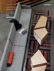
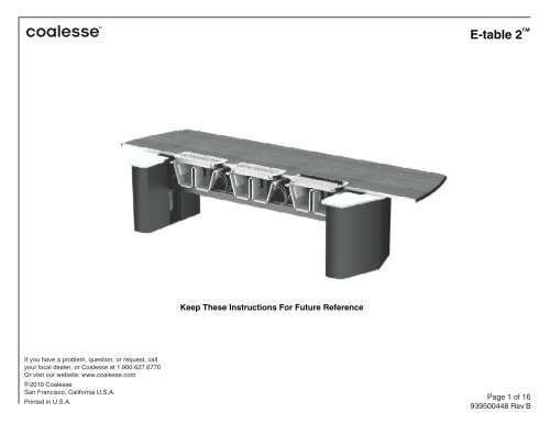
E-<strong>table</strong> 2Keep These Instructions For Future ReferenceIf you have a problem, question, or request, callyour local dealer, or <strong>Coalesse</strong> at 1.800.627.6770Or visit our website: www.coalesse.com© 2010 <strong>Coalesse</strong>San Francisco, California U.S.A.Printed in U.S.A.Page 1 of 16939500448 Rev B
BEFORE YOU BEGIN: Make sure you have all the <strong>table</strong> components:Table top- (1) piece <strong>table</strong> top OR- multiple piece <strong>table</strong> top. Tite-Joint Fasteners will be includedTable bases- (2) bases for <strong>table</strong>s 12' or shorter OR- (3) bases for <strong>table</strong>s from 14', up to 20' long OR- (4) bases for <strong>table</strong>s over 20’ longNOTE: UTILITY BAYS ARE SHIPPED INSIDE BASE CARTONS. Make sure all Utility Bays are located and removed before discarding thebase cartons.Wireway Assembly- (1) power infeed - There are three types: four-circuit hardwire, NYC four-circuit hardwire, or 20-amp single-circuit plug.- (1) Wireway <strong>assembly</strong> for two-base <strong>table</strong>s, OR- (2) Wireway assemblies for three-base <strong>table</strong>s OR- (3) Wireway assemblies for four-base <strong>table</strong>sEach Wireway <strong>assembly</strong> consists of:(2) black steel "C"-shaped beams, with one or more gray steel "W"-shaped inserts attached.(2) Black steel side panels. These will be shipped partially installed.(1) black plastic bottom access doorHardware- #10-24 x 1/2" Pan-Head Phillips machine screws, black. Quantity varies with <strong>table</strong> size and configuration. Vecta part #73053702- (Laminate and Veneer base <strong>table</strong>s only) #10 Type A X 1-1/4" Pan-Head Phillips wood screws, black. Quantity varies with <strong>table</strong> size andconfiguration. Vecta part #73030401- #12 Type A x 1” Pan Head Phillips wood screws, black. Quantity varies with <strong>table</strong> size and configuration. Vecta part #730430- Conduit Clamp, #10 x 3/4” wood screw, #10 x 3/4” bolt and nut`Duplex OutletsThese are ordered separately from the <strong>table</strong> but will be factory installed. Duplexes are identified with numbers corresponding to their circuits: 1through 4. On Circuit 1 duplexes will work with single circuit plug infeed.Optional- Floor Monument Cover- Flexible cord conduitTOOLS REQUIRED:- Drill driver with #2 and #3 Phillips head bits- Short (less than 6" long ) Phillips screwdriver, #2- Rubber Mallet and Nail Set (for Tite Joint Fasteners on two piece tops)NOTE REGARDING HARDWIRE POWER IN-FEEDSA LICENSED ELECTRICIAN MUST CONNECT THE POWER IN-FEED (S) TO THE BUILDING POWER SOURCE IN ACCORDANCE WITH ALL NATIONAL AND LOCALELECTRICAL CODES. THESE ELECTRICAL ASSEMBLIES ARE INTENDED FOR INSTALLATION IN ACCESSIBLE DRY LOCATIONS IN ACCORDANCE WITH ARTICLE 604OF THE NATIONAL ELECTRIC COD NFPA70. IF YOU HAVE ANY CONCERNS ABOUT A SPECIFIC APPLICATION PLEASE CONSULT THE LOCAL AUTHORITY HAVINGJURISDICTION. THIS SYSTEM IS RATED FOR A MAXIMUM OF 20 AMPS, 125/250 V, 1-PHASE, 60Hz OR 120/208 V, 3-PHASE, 60Hz.WARNING: “RISK OF FIRE OR ELECTRICAL SHOCK. DO NOT ELECTRICALLY CONNECT TO MORE THAN ONE SOURCE OF SUPPLY. ALWAYS DETERMINE THAT THEWIRING ASSEMBLY IS ELECTRICALLY CONNECTED TO ONE AND ONLY ONE SOURCE OF SUPPLY”Page 2 of 16939500448 Rev B
Wiring SchematicHardwareFour-Circuit, 3+1 also known as a 3+D (color-coded black). Thefourth circuitis isolated and has its own neutral.Three-Circuit Separate NeutralsThree circuits are each provided with their own neutral wire.PN 73053702#10-24 X 1/2"machine screwsPN 730430#12 Type A X1" Pan HeadPhillips woodNOTE:BE CAREFUL!Only use the 1¼ longwood screw toconnect bases to the<strong>table</strong> top.See page 12.PN 73030401#10 Type A XHead Philips woodscrews.In the four-circit, 3+1 schematic, circuits 1,2, and 3 are distributedfrom the first circuit panel and are supported with one shared neutraland one shared ground. Circuit 4 is distributed from a second circuitpanel and is supported with a separate neutral and ground.In the three-circuit, separate neutral schematiccircuits 1 and 2 are distributed from two different phases from the firstcircuit panel. Each circuit is supported with its own neutral and a commonground. Circuit 3 is distributed from the second circuit panel and issupported by its own neutral and ground.On a single 3-phase circuit panel, all four circuits aredistributed as shownOn a single 3-phase circuit panel, all four circuits are distributed as shownOn a split-phase circuit panel, all four circuits are distributed as shownPage 3 of 16939500448 Rev B
1. DETERMINE FINAL LOCATION OF THE TABLEThe <strong>table</strong> base can be placed directly over a flush-floor monument no larger than 6 3/4” diameter (shown),or adjacent to either a flush floor or above floor monument.2a2b2. LOCATE AND INSTALL THE POWER INFEED(Note: A licensed electrician can install the power infeed before, during, or after the <strong>table</strong> <strong>assembly</strong>process.)There are three power infeed options available: 4-circuit hardwire (2a), single-circuit plug (2b), or 4-circuithardwire-New York version (2c). Remove the infeed from the beam <strong>assembly</strong> box.2cHardwire power infeeds must be installed by a licensed electrician in accordance with all local codes.See the Note on page 2 of these instructions and the wiring schematic on page 3.Page 4 of 16939500448 Rev B
3. PULL THE POWER INFEED UP THROUGH THE BASE.Remove the base access door. Pull the infeed up through the base and out the opening in the top.Communications cables (not shown) should also be pulled through the base at this time.Attach the conduit clamp to the inside of the drum base as shown, secure the power in-feed harness tothe clamp.NOTE: The conduit clamp attachment shown is for the drum base only.The New York City infeed box should be attached to the inside of the base using the hook and loopfasteners provided. The box should be positioned so that the door of the box is accessible through thebase access door, and so that the steel conduit will pass through the opening at the bottom of the baseaccess door.NOTE:NYC Infeed:NYC Department of BuildingsBureau of Electrical ControlCalendar #37297Page 5 of 16939500448 Rev B
4. Remove the side panels from the Wireway <strong>assembly</strong>.The Wireway Assembly is shipped with its side panels installed. These will need to be removed beforeproceeding.Remove and retain the screws on both the sides and the bottom of the beam side panels.Remove the screws holding on both side panels from the bottom and sides of both panels.5. Set the beam into the brackets on the basesFor <strong>table</strong>s with three bases, attach the second beam <strong>assembly</strong> the same way.If the <strong>table</strong> has two beams, a sticker at one end of each beam shows the correct orientation ofthe beam to the base.Page 6 of 16939500448 Rev B
6. Attach the beams to the base bracketsEach universal base bracket has a color-coded sticker that indicates the correct mounting position forthe beam depending on the type of base. IT IS EXTREMELY IMPORTANT THAT THE BEAM ISMOUNTED USING THE CORRECT HOLES!Attach the power in-feed conduit clamp to the base bracket as shown. Attach conduit to clamp.NOTE: The conduit clamp attachment shown is for all laminate and veneer 24”/30” end and midsupport bases and all aluminum 30”/36” end support and 36” mid support bases.Page 7 of 16939500448 Rev B
Each C-beam will be attached to each base bracket with a total of three screws, but only two will beinstalled now.Carefully refer to the diagram on the sticker and install screws in the first and third lacations only. Themiddle screw locations will be left open for now.Repeat for both sides of each bracket, for a total of eight screws.Page 8 of 16939500448 Rev B
7. (FOR THREE OR FOUR-BASE TABLES ONLY) CONNECT JUMPER FROM ONE WIREWAY TOTHE NEXT WIREWAY(On all two-base <strong>table</strong>s, the jumpers connecting power blocks are factory-installed).On three or four-base <strong>table</strong>s, a jumper (or jumpers) must be field installed to connect the last powerblock on one beam to the first power block on the next beam.One end will be connected to the power block at the factory. Depending on the exact specifications,there are two different ways the other end may need to be connected.Depending on the configuration and length of the <strong>table</strong> the connection from one beam to the next beammay require multiple jumpers. If more than one jumper is required, they will be supplied with anH-Connector that is used to connect one jumper to another.JumperH-ConnectorH-ConnectorNext jumperconnectedto H-ConnectorFirst jumper connected to last power blockOther versions of the <strong>table</strong> only use jumper. In this case, the utility bay insert (gray steel) must beremoved to access the power block connection. Remove all the screws holding the insert to the beams.Carefully pull the insert off and make the jumper connection to the exposed block. Replace the insertand screws.Remove thisinsert to accessthe power block.Page 9 of 16939500448 Rev B
C-Beam10. Install the bottom and side panelsSnap the curved edge of the plastic bottom access door onto one of the steel beams, aligning the clearanceholes in the plastic with the holes in the steel.Snap on hereBottom access doorPlace the side panel over the beam with the access door sandwiched between the beam and the sidepanel, and screw into place.Screw on the other side panel.On two-base <strong>table</strong>s, the side panels will be symmetrical. On three or four-base <strong>table</strong>s, make sure the sidepanel is oriented as indicated by the sticker at one end of the panel (reference step 5).Use machine screws to attach the side panels to:• bottom of the base brackets,• bottom of the C-shaped beams• sides of all the gray insertsMiddle screw into basebracket - see step 6Page 11 of 16939500448 Rev B
11. Install <strong>table</strong> top: two-base <strong>table</strong>sCarefully set the <strong>table</strong> top into place on top of the completed base/wireway <strong>assembly</strong>. There arepredrilled pilot holes in the <strong>table</strong> top for connecting the base and the side panels. Line up these holes inthe top with the corresponding holes in the base/wireways <strong>assembly</strong>.Attach the toop using the wood screws provided.EXTREMELY IMPORTANT!!!Only use 1” long wood screws to attach side panels to the <strong>table</strong> top. Longer screws maydamage the <strong>table</strong> surface.1¼” long screws should be used to attach laminate or veneer bases to the top.Attach base to<strong>table</strong> topAttach side panelsto <strong>table</strong> topPage 12 of 16939500448 Rev B
BE CAREFUL NOT TO DAMAGE THE TOP!12. Install the Tite-Joint fasteners on multi-piece <strong>table</strong> tops (If the <strong>table</strong> top is one piece, see step 11).If the top is a multi-piece top, Tite-Joint Fasteners will need to be installed before connecting the top to thebase <strong>assembly</strong>.Carefully remove the protective wood strips from the joining edges of the <strong>table</strong>top sections, prying from theunderside of the top to loosen. Be very careful not to damage the veneer or laminate when removing thesestrips.Several installers should carefully lift each section of the <strong>table</strong>top and place them on the base / beam<strong>assembly</strong> about 12” off center. Care should be taken to make sure <strong>table</strong>top sections are securely supporteduntil they can be attached to the base <strong>assembly</strong>. The sections will need to be spread apart about 12" toprepare the Tite-Joint Fasteners for <strong>assembly</strong>.The Tite-Joint Fastener consists of three parts: the Tightening Nut, the Draw Bolt, and the Locking Sleeve.NOTE: Leave gapfor installingTite JointsInsert the Tightening Nuts into the <strong>table</strong>top halves, alternating halves across the width of the top, with thethreaded ends of the nuts towards the joint. Insert the draw bolts and thread into the nut.The base/beam <strong>assembly</strong> will cover some holes. Carefully slide the top half over to one side, balancing itcarefully, to access these holes. Install the nuts and bolts, and then re-center the top.NOTE: Draw Bolts installedon alternating sidesSlide top over asnecessary to accesscenter Tite Joint holesAfter all nuts and draw bolts have been installed, carefully line up the other <strong>table</strong> top section with the drawbolts, and slide the halves together.Draw BoltTightening NutLocking SleevePage 13 of 16939500448 Rev B
Insert the locking sleeves so the notch in the sleeve engages the rounded portion of the draw bolt.At this time, only install the locking sleeves in those locations that are accessible (the sleeves for the centerbolts will be installed later).Tighten the nuts using a nail set. Tighten the nuts to the point where they are friction-tight only.Carefully slide the two connected top halves over to one side, and install the locking sleeves in the remainingholes as described above. Make sure the top <strong>assembly</strong> is well supported during this process.Beginning with the center Tite-Joints, slowly tighten the nuts completely, making sure the center two feet ofthe top is leveled and aligned.Center the top <strong>assembly</strong> back into the final location on the base <strong>assembly</strong>, and continue tightening nutswhile leveling and aligning the top sections.Level top halvesbefore tighteningA rubber mallet can used to aid in leveling the top sections, provided that care is taken not to damage thetop.Page 14 of 16939500448 Rev B
13. Installing Bombay doorsThe Bombay doors are shipped inside the base cartons. They should be installed with the buttons facingtoward the closest end of the <strong>table</strong>.Each Bombay door has four tabs that should be depressed when installing so as not to damage the <strong>table</strong>top.Set the door <strong>assembly</strong> into place and depress each of the four tabs while inserting that corner into the top.When all four tabs are inside the top, press the whole <strong>assembly</strong> into place until it clicks.To remove the door <strong>assembly</strong>, you can grasp the entire <strong>assembly</strong> and pull it loose from the top by defeatingthe tabs, then pulling the <strong>assembly</strong> from the <strong>table</strong>.Page 15 of 16939500448 Rev B
APPENDIX A:OPTIONAL FLOOR MONUMENT KITIf the optional Floor Monument Kit is supplied, install it over the floor monument and cords. Cutout the grommet in the base door and run wires and cables through the grommet. Insert theend of the Cord Conduit into the grommet opening (”friction fit”).Knockout in base accessFloor Monument Kit P/N 793369Page 16 of 16939500448 Rev B