

7-Sonic-Nozzle-Test
7-Sonic-Nozzle-Test
7-Sonic-Nozzle-Test

Create successful ePaper yourself
Turn your PDF publications into a flip-book with our unique Google optimized e-Paper software.
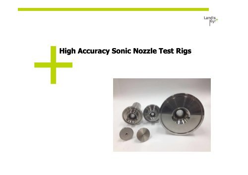
High Accuracy <strong>Sonic</strong> <strong>Nozzle</strong> <strong>Test</strong> Rigs
Basics of <strong>Sonic</strong> <strong>Nozzle</strong> <strong>Test</strong>ingThe Meter Under <strong>Test</strong> and the Volume Reference Standardare located in a temperature controlled test room and air isdrawn from the room through both the Meter Under <strong>Test</strong>and the reference standard in series. Temperature stabilityis very important in measurement so the meter under testshould always be in the test room for a suitable period oftime to acclimatise.2 – Landis+Gyr – Antony Cockshott
Critical Flow Venturi <strong>Nozzle</strong>s ISO9300+Critical Flow Venturi <strong>Nozzle</strong>s are designed andmanufactured to have a smooth, geometricallysymmetrical internal shape with a very smooth roundedinlet section converging to a minimum throat area anddiverging along a pressure recovery section.+The Critical Flow Venturi <strong>Nozzle</strong>s are designed to therequirements as detailed in the Standard ISO9300.3 – Landis+Gyr – Antony Cockshott
Critical Flow Venturi <strong>Nozzle</strong>s ISO93004 – Landis+Gyr – Antony Cockshott
Flow through a <strong>Sonic</strong> <strong>Nozzle</strong>As a gas acceleratesthrough the <strong>Nozzle</strong>, itsvelocity increases and itsdensity decreases.The maximum velocity isachieved at the throat,the minimum area, whereit just reaches Mach 1 orcritical flow.The flow then slowsagain as pressure isrecovered in the exitdivergent section of thenozzle.5 – Landis+Gyr – Antony Cockshott
<strong>Sonic</strong> Flow at the Throat+ By decreasing the pressure P2downstream eventually a point isreached where the velocity of the airreaches the local speed of sound (MachNumber =1) at the Throat.+ This occurs when P2
Flow Rate Under Real Conditions+ A nt = Cross sectional area of the sonicnozzle+ C d’ = Discharge coefficient (ISO9300)+ C * = Critical flow function (Air) (ISO9300)+ P o = Stagnation pressure (Abs) sonicnozzle inlet+ R=Universal Gas Constant+ M=Molar Mass (Air)+ T o =Stagnation Temperature (Abs) atsonic nozzle inlet+ C R = Critical flow coefficient+ Zo=Compressibility Factor at upstreamstagnation conditions7 – Landis+Gyr – Antony Cockshott
Air is Not an Ideal Gas+ The compressibility factor Z expresses the deviation from the idealgas laws at a given pressure and temperature for air Z≠1.+ The density of air varies as the temperature and moisture content inthe air varies. When the temperature increases the higher molecularmotion results in an expansion of the volume and thus decreasing thedensity.+ For the sonic nozzle equations in ISO9300 we need to know thecompressibility factor Z of the humid air and the density of the humidair (at the given Pressure and Temperature).+ The equation of the density of moist air requires input values for airtemperature, pressure and relative humidity (or dew-pointtemperature).8 – Landis+Gyr – Antony Cockshott
<strong>Sonic</strong> <strong>Nozzle</strong> Calculations9 – Landis+Gyr – Antony Cockshott
Repeatability of a <strong>Sonic</strong> <strong>Nozzle</strong> Prover<strong>Sonic</strong> <strong>Nozzle</strong> Repeatability Data20/10/2011 to 15/03/20120.30.20.10-0.120/10/201122/10/201124/10/201126/10/201128/10/201130/10/20111/11/20113/11/20115/11/20117/11/20119/11/201111/11/201113/11/201115/11/201117/11/201119/11/201121/11/201123/11/201125/11/201127/11/201129/11/20111/12/20113/12/20115/12/20117/12/20119/12/201111/12/201113/12/201115/12/201117/12/201119/12/201121/12/201123/12/201125/12/201127/12/201129/12/201131/12/20112/01/20124/01/20126/01/20128/01/201210/01/201212/01/201214/01/201216/01/201218/01/201220/01/201222/01/201224/01/201226/01/201228/01/201230/01/20121/02/20123/02/20125/02/20127/02/20129/02/201211/02/201213/02/201215/02/201217/02/201219/02/201221/02/201223/02/201225/02/201227/02/201229/02/20122/03/20124/03/20126/03/20128/03/201210/03/201212/03/201214/03/2012-0.2-0.3Elster RVG Meter G16 Qmax, Repeatability ± 0.043% <strong>Test</strong> EquipmentSNIP4 Uncertainty ± 0.22%, 5 months 100 total tests.10 – Landis+Gyr – Antony Cockshott
Uncertainty of a <strong>Sonic</strong> <strong>Nozzle</strong> Prover+ Sources of Error- Pressure Measurement- Temperature Measurement- Relative Humidity (or Dew Point or Density)- Time Measurement- Analogue / Digital Converters- Initial Certification (Reference Flow Rate)+ Uncertainty typically ± 0.20 to 0.25 %11 – Landis+Gyr – Antony Cockshott
<strong>Sonic</strong> <strong>Nozzle</strong>s in Combination ( 2 n -1 )2^10-1=1023, 2^7-1=127, 2^6-1=63, 2^5-1=3112 – Landis+Gyr – Antony Cockshott
Domestic <strong>Sonic</strong> <strong>Nozzle</strong> Rig x 3+ <strong>Test</strong>ing Domestic Gas Meters, 3 Stations+ The CAPS utilises five installed critical flow venturinozzles for 0.5, 1.2, 1.6, 4.7, 6, 7.3, 8 and 9.6 m 3 /h+ First placed in operation March 2009+ Best Measurement Capability +/-0.20 %+ Capable of testing gas meters up to 10 m 3 /h+ CAPS has an automatic clamping fixture specificallydesigned for meter models 610, 602, 750 & 1010+ Fixed mass flow rate for a specified temperature,pressure and nozzle geometry when sonic velocity isachieved+ Regulation 13 Certified to the National MeasurementAct 196013 – Landis+Gyr – Antony Cockshott
Domestic <strong>Sonic</strong> <strong>Nozzle</strong> Rig x 314 – Landis+Gyr – Antony Cockshott
Sneak Peek – MAPS New Domestic <strong>Sonic</strong> <strong>Nozzle</strong> Rig15 – Landis+Gyr – Antony Cockshott
Sneak Peek – MAPS New Domestic <strong>Sonic</strong> <strong>Nozzle</strong> Rig16 – Landis+Gyr – Antony Cockshott
<strong>Sonic</strong> <strong>Nozzle</strong> Industrial Prover No 1+ The SNIP utilises six critical flowventuri nozzles that can be used in63 various flow rate combinations.Capable of testing gas meters up to25 cubic metres per hour+ First placed into operation April 2008+ Regulation 13 Certified in accordancewith the National Measurement Act1960. Best Measurement CapabilityEstimated +/-0.2 %.+ Fixed mass flow rate for a specifiedtemperature, pressure and nozzlegeometry when sonic velocity isachieved.+ Meters AL425 @ 2” Diff, AL425,AC630 @ ½” Diff.+ The testing is fully computerised withresults stored on a remote server.+ Automated test data formats &delivery17 – Landis+Gyr – Antony Cockshott
<strong>Sonic</strong> <strong>Nozzle</strong> Industrial Prover No 118 – Landis+Gyr – Antony Cockshott
<strong>Sonic</strong> <strong>Nozzle</strong> Industrial Prover No 2+ Designed to do AL425,630,800 & 1000+ SNIP No 2 utilises seven critical flowventuri nozzles that can be used in 127various flow rate combinations+ Fixed mass flow rate for a specifiedtemperature, pressure and nozzlegeometry when sonic velocity is achieved+ Capable of testing gas meters up to 61cubic metres per hour+ Best Measurement Capability+/-0.25 %+ The testing is fully computerised withresults stored on a remote server.+ Automated test data formats & delivery+ Placed into operation May 2009+ Regulation 13 Certified to the NationalMeasurement Act 196019 – Landis+Gyr – Antony Cockshott
What is SNIPW7 ?+ The SNIPW7 System is a meter verification prover used to test industrial gasmeters. SNIPW7 Systems are the next generation of test equipment which isbuilt upon the original SNIP (<strong>Sonic</strong> <strong>Nozzle</strong> Industrial Prover) system developedin 2008. However the SNIPW7 System has been upgraded with the followingfeatures;- Compatibility with Microsoft Windows7 Operating System- Compatibility with Microsoft .Net Framework (VB.Net)- Allow testing of meters with high frequency outputs 0.00084 to 5000 Hz- Allow testing of meters using 1 or 2 Transfer Standard Meters (TSM)Typical Flow rates typically 200 to 6,500 m 3 /h- Allow up to 10 sonic nozzle combinations (original SNIP was limited to 7)- 10 sonic nozzle combinations= Potentially 1023 flow combinations !- Typical Flow rates 0.5 to 500 m 3 /h- Fully automated test procedures- Regulation 13 Certified to the National Measurement Act 196020 – Landis+Gyr – Antony Cockshott
SNIPW721 – Landis+Gyr – Antony Cockshott
SNIPW722 – Landis+Gyr – Antony Cockshott
Meter Details23 – Landis+Gyr – Antony Cockshott
<strong>Test</strong> Setup Screen – Meter Details24 – Landis+Gyr – Antony Cockshott
<strong>Test</strong> Screen25 – Landis+Gyr – Antony Cockshott
<strong>Test</strong> Finish Screen26 – Landis+Gyr – Antony Cockshott
Manual Control Screen27 – Landis+Gyr – Antony Cockshott
Any Questions?+ Thanks for listening, and have a nice day!30 – Landis+Gyr – Antony Cockshott