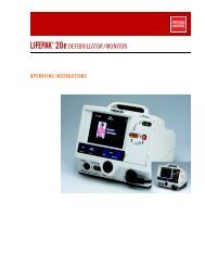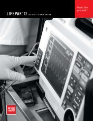
LIFEPAK 12 Defibrillator/Monitor Operating ... - Physio Control
LIFEPAK 12 Defibrillator/Monitor Operating ... - Physio Control
LIFEPAK 12 Defibrillator/Monitor Operating ... - Physio Control

You also want an ePaper? Increase the reach of your titles
YUMPU automatically turns print PDFs into web optimized ePapers that Google loves.
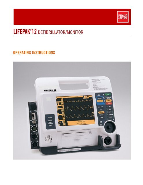
®<strong>LIFEPAK</strong> <strong>12</strong> DEFIBRILLATOR/MONITOROPERATING INSTRUCTIONS
®<strong>LIFEPAK</strong> <strong>12</strong> DEFIBRILLATOR/MONITOROPERATING INSTRUCTIONS
IMPORTANT INFORMATION!USARx OnlyDevice Tracking!USA The U.S. Food and Drug Administration requires defibrillator manufacturers and distributors totrack the location of their defibrillators. If the device is located somewhere other than the shippingaddress or the device has been sold, donated, lost, stolen, exported, destroyed, permanently retiredfrom use, or if the device was not obtained directly from <strong>Physio</strong>-<strong>Control</strong>, please do one of thefollowing: register the device at http://www.physio-control.com, call the device tracking coordinator at1.800.426.4448, or use one of the postage-paid address change cards located in the back of thismanual to update this vital tracking information.Responsibility for InformationIt is the responsibility of our customers to ensure that the appropriate person(s) within their organizationhave access to this information, including general safety information provided in Section 1.Version HistoryThese operating instructions describe <strong>LIFEPAK</strong> <strong>12</strong> defibrillator/monitor devices with software version3011371-065 or later. Older devices may not have all the features described in this manual. Softwareversion 3011371-106 or later will not work in monophasic devices.<strong>Operating</strong> Instructions Version<strong>Operating</strong> Software Version*PN 30100<strong>12</strong>-000 PN 3011371-018PN 30100<strong>12</strong>-001 PN 3011371-019 and PN 3011371-022PN 30100<strong>12</strong>-003 PN 3011371-030PN 30100<strong>12</strong> (-005 international; -006 USA only) PN 3011371-061PN 30100<strong>12</strong>-007 (USA only) PN 3011371-062PN 30<strong>12</strong>730-000 (addendum) PN 3011371-065PN 30100<strong>12</strong> (-008 and -009 USA only; -050 international) PN 3011371-065PN 30100<strong>12</strong> (-010 and -011 USA only; -051 international) PN 3011371-067, -070PN 30100<strong>12</strong> (-0<strong>12</strong> and -013 USA only; -052 international) PN 3011371-072PN 30100<strong>12</strong> (-014 USA only; -053 international) PN 3011371-072PN 30100<strong>12</strong> (-015 USA only; -020 international) PN 3011371-090PN 30100<strong>12</strong> (-016 USA only; -021 international) PN 3011371-099MIN 30100<strong>12</strong> (-017 USA only; -022 international) MIN 3011371-101MIN 30100<strong>12</strong> (-018 USA only; -023 international) MIN 3011371-106MIN 30100<strong>12</strong> (-019 USA only; -024 international) MIN 3011371-106MIN 3207254 (-001 USA only; -021 international) MIN 3011371-<strong>12</strong>6MIN 3207254 (-002 USA only; -022 international) MIN 3011371-130MIN 3207254 (-006 USA only; -026 international) MIN 3011371-134MIN 3207254 (-007 USA only; -027 international) MIN 3011371-134* To view the operating software version, turn on the device and note the PN after VERSION on theopening screen.<strong>LIFEPAK</strong>, LIFENET, FASTPAK, FAST-PATCH, QUIK-COMBO, QUIK-LOOK, and QUIK-CHARGE are registered trademarks of <strong>Physio</strong>-<strong>Control</strong>, Inc. CODE SUMMARY, ShockAdvisory System, CODE-STAT, cprMAX, and REDI-PAK are trademarks of <strong>Physio</strong>-<strong>Control</strong>, Inc. CADEX is a registered trademark of Cadex Electronics Inc. <strong>12</strong>SL is a trademark of GEMedical Systems. C-LOCK, Dura-Y, Durasensor, Nellcor, Oxiband, OxiCliq, and Oxisensor are registered trademarks of Nellcor. PediCheck is a trademark of Nellcor. Microstreamand FilterLine are trademarks of Oridion Medical Ltd. The Oridion medical capnography in this product is covered by one or more of the following US patents: 6,428,483; 6,997,880;5,300,859; 6,437,316 and their foreign equivalents. Additional patent applications pending. STERRAD is a registered trademark of Advanced Sterilization Products, a Johnson andJohnson Company. PC Card is a trademark of the Personal Computer Memory Card International Association. SPUNGUARD is a registered trademark of Kimberly-Clark Corporation.Masimo and LNOP are registered trademarks of Masimo Corporation. EDGE System Technology is a trademark of Ludlow Technical Products. UNI-LEAD is a trademark of UnileadInternational, Inc. DTXPlus is a trademark of BD Medical. Specifications are subject to change without notice.© 2008 <strong>Physio</strong>-<strong>Control</strong>, Inc. All rights reserved.Publication date: <strong>12</strong>/2008MIN 3207254-008ii<strong>LIFEPAK</strong> <strong>12</strong> <strong>Defibrillator</strong>/<strong>Monitor</strong> <strong>Operating</strong> Instructions
TABLE OF CONTENTSPrefaceAbout Automated External Defibrillation .........................................................................................xAbout Defibrillation Therapy............................................................................................................xAbout Noninvasive Pacing .............................................................................................................xiAbout <strong>12</strong>-Lead Electrocardiography...............................................................................................xiAbout SpO2 <strong>Monitor</strong>ing................................................................................................................. xiiAbout NIBP <strong>Monitor</strong>ing.................................................................................................................. xiiAbout End-Tidal CO2 (EtCO2) <strong>Monitor</strong>ing ................................................................................... xiiiAbout Invasive Pressure (IP) <strong>Monitor</strong>ing...................................................................................... xiiiAbout Vital Sign and ST <strong>Monitor</strong>ing ............................................................................................. xiiiAbout ECG <strong>Monitor</strong>ing ................................................................................................................. xiiiText Conventions ......................................................................................................................... xiv1 Safety InformationTerms .......................................................................................................................................... 1-2General Warnings and Cautions ................................................................................................. 1-2Symbols ...................................................................................................................................... 1-32 Basic OrientationIntroduction ................................................................................................................................. 2-2Unpacking and Inspecting........................................................................................................... 2-3<strong>Control</strong>s, Indicators, and Connectors.......................................................................................... 2-3Area 3 .................................................................................................................................. 2-8Area 4 ................................................................................................................................ 2-11Area 6 ................................................................................................................................ 2-15Back View .......................................................................................................................... 2-19Entering Patient Data ................................................................................................................ 2-20Setting Alarms........................................................................................................................... 2-22Managing Alarms ...................................................................................................................... 2-24Connecting to Power................................................................................................................. 2-25Batteries............................................................................................................................. 2-25Understanding Batteries and Battery Support Systems..................................................... 2-25Installing/Removing Batteries ............................................................................................ 2-28<strong>LIFEPAK</strong> <strong>12</strong> <strong>Defibrillator</strong>/<strong>Monitor</strong> <strong>Operating</strong> Instructions© 2008 <strong>Physio</strong>-<strong>Control</strong>, Inc.iii
3 <strong>Monitor</strong>ing<strong>Monitor</strong>ing the ECG .....................................................................................................................3-2ECG <strong>Monitor</strong>ing Warning......................................................................................................3-2Selecting ECG Lead and Size ..............................................................................................3-2Adjusting the Systole Volume...............................................................................................3-4<strong>Monitor</strong>ing ECG with Paddles Accessories ..........................................................................3-4<strong>Monitor</strong>ing with the Patient ECG Cable ................................................................................3-5Troubleshooting Tips for ECG <strong>Monitor</strong>ing ............................................................................3-8Acquiring a <strong>12</strong>-Lead ECG............................................................................................................3-9<strong>12</strong>-Lead ECG Warning .........................................................................................................3-9Identifying Electrode Sites ....................................................................................................3-9<strong>12</strong>-Lead ECG Procedure ....................................................................................................3-11<strong>12</strong>-Lead ECG Reports ........................................................................................................3-<strong>12</strong>Computerized ECG analysis...............................................................................................3-14Troubleshooting Tips for <strong>12</strong>-Lead ECG..............................................................................3-15<strong>Monitor</strong>ing SpO2........................................................................................................................3-16SpO2 Warnings and Cautions ............................................................................................3-16No Implied License .............................................................................................................3-17When to Use a Pulse Oximeter ..........................................................................................3-17How a Pulse Oximeter Works.............................................................................................3-17SpO2 <strong>Monitor</strong>ing Considerations........................................................................................3-18Masimo SpO2 <strong>Monitor</strong>ing Procedure..................................................................................3-18Nellcor SpO2 <strong>Monitor</strong>ing Procedure...................................................................................3-20Cleaning..............................................................................................................................3-22Troubleshooting Tips for SpO2...........................................................................................3-23<strong>Monitor</strong>ing Noninvasive Blood Pressure (NIBP) .......................................................................3-24NIBP <strong>Monitor</strong>ing Warnings .................................................................................................3-24When to Use NIBP..............................................................................................................3-25How NIBP Works................................................................................................................3-25NIBP <strong>Monitor</strong>ing Considerations.........................................................................................3-26Cuff Selection .....................................................................................................................3-26NIBP <strong>Monitor</strong>ing Procedures ..............................................................................................3-26Changing the Initial Inflation Pressure................................................................................3-26Manual Single-Measurement Procedure ............................................................................3-27Timer-<strong>Control</strong>led Measurement Procedure ........................................................................3-27Cleaning and Maintenance.................................................................................................3-28Troubleshooting Tips for NIBP <strong>Monitor</strong>ing..........................................................................3-28<strong>Monitor</strong>ing EtCO2 ......................................................................................................................3-29EtCO2 <strong>Monitor</strong>ing Warnings...............................................................................................3-30When to Use EtCO2 <strong>Monitor</strong>ing .........................................................................................3-30How Capnography Works...................................................................................................3-30EtCO2 <strong>Monitor</strong>ing Waveform Analysis ...............................................................................3-31EtCO2 <strong>Monitor</strong>ing Procedure..............................................................................................3-32CO2 Scale Options.............................................................................................................3-33CO2 Alarms ........................................................................................................................3-33Cleaning and Maintenance.................................................................................................3-33Troubleshooting Tips for EtCO2 <strong>Monitor</strong>ing .......................................................................3-34<strong>Monitor</strong>ing Invasive Pressure (IP)..............................................................................................3-35IP <strong>Monitor</strong>ing Warnings ......................................................................................................3-35When to Use IP...................................................................................................................3-35How IP Works.....................................................................................................................3-36IP <strong>Monitor</strong>ing Considerations..............................................................................................3-36IP <strong>Monitor</strong>ing Procedure.....................................................................................................3-36Cleaning and Maintenance.................................................................................................3-37Troubleshooting Tips for IP <strong>Monitor</strong>ing...............................................................................3-37<strong>Monitor</strong>ing Vital Signs (VS) and ST Changes............................................................................3-39VS and ST <strong>Monitor</strong>ing Warning ..........................................................................................3-39iv<strong>LIFEPAK</strong> <strong>12</strong> <strong>Defibrillator</strong>/<strong>Monitor</strong> <strong>Operating</strong> Instructions
When to Use VS and ST <strong>Monitor</strong>ing ..................................................................................3-39How VS and ST <strong>Monitor</strong>ing Work.......................................................................................3-40VS and ST <strong>Monitor</strong>ing Considerations ...............................................................................3-41VS and ST <strong>Monitor</strong>ing Procedure.......................................................................................3-414TherapyGeneral Therapy Warnings and Cautions ...................................................................................4-2Therapy Electrode and Standard Paddle Placement ..................................................................4-3Anterior-lateral Placement....................................................................................................4-3Anterior-posterior Placement................................................................................................4-3Automated External Defibrillation ................................................................................................4-4AED Warnings......................................................................................................................4-4AED Configuration................................................................................................................4-4AED Procedure ....................................................................................................................4-4Special AED Setup Options .................................................................................................4-9Advisory <strong>Monitor</strong>ing............................................................................................................4-11Troubleshooting Tips for AED Mode ..................................................................................4-<strong>12</strong>Manual Defibrillation ..................................................................................................................4-13Manual Defibrillation Warnings...........................................................................................4-13Switching from AED to Manual Mode.................................................................................4-13Defibrillation Shock Overlays .............................................................................................4-14Defibrillation Procedure ......................................................................................................4-15Synchronized Cardioversion Procedure.............................................................................4-16Troubleshooting Tips for Defibrillation and Synchronized Cardioversion...........................4-17Noninvasive Pacing ...................................................................................................................4-18Noninvasive Pacing Warnings............................................................................................4-18Demand and Nondemand Pacing ......................................................................................4-19Noninvasive Pacing Procedure ..........................................................................................4-19Troubleshooting Tips for Noninvasive Pacing ....................................................................4-205 Paddle Accessory OptionsTherapy Electrodes .....................................................................................................................5-2About Therapy Electrodes....................................................................................................5-2Electrode Placement ............................................................................................................5-3Cable Connection.................................................................................................................5-4ECG <strong>Monitor</strong>ing and Therapy Procedures ...........................................................................5-4Replacing and Removing Electrodes ...................................................................................5-5Testing..................................................................................................................................5-6Cleaning and Sterilizing........................................................................................................5-6Pediatric Paddles (PN 800418) ...................................................................................................5-6About Pediatric Paddles .......................................................................................................5-6Attaching Pediatric Paddles .................................................................................................5-6Removing Pediatric Paddles ................................................................................................5-7Paddle Placement ................................................................................................................5-7Defibrillation Procedure ........................................................................................................5-8Cleaning and Sterilizing........................................................................................................5-9External Sterilizable Paddles (PN 3009166)................................................................................5-9About External Sterilizable Paddles .....................................................................................5-9ECG <strong>Monitor</strong>ing and Therapy Procedures ...........................................................................5-9Cleaning and Sterilizing........................................................................................................5-9Internal Handles with Discharge <strong>Control</strong> (PN 3010901) ............................................................5-10About Internal Handles with Discharge <strong>Control</strong>..................................................................5-10Inserting the Paddles..........................................................................................................5-10Removing the Paddles .......................................................................................................5-11Internal Defibrillation Procedure .........................................................................................5-11Internal Paddles Synchronized Cardioversion Procedure..................................................5-11Handling Internal Paddles ..................................................................................................5-<strong>12</strong><strong>LIFEPAK</strong> <strong>12</strong> <strong>Defibrillator</strong>/<strong>Monitor</strong> <strong>Operating</strong> Instructions© 2008 <strong>Physio</strong>-<strong>Control</strong>, Inc.v
Cleaning and Sterilizing......................................................................................................5-<strong>12</strong>Cleaning and Sterilization Guidelines ........................................................................................5-<strong>12</strong>Cleaning..............................................................................................................................5-<strong>12</strong>STERRAD Hydrogen Peroxide Gas Plasma Sterilization...................................................5-<strong>12</strong>6 Data ManagementOverview of Data Storage and Retrieval......................................................................................6-2Data Storage.........................................................................................................................6-2Report Types ........................................................................................................................6-2Memory Capacity..................................................................................................................6-2Report Retrieval....................................................................................................................6-2CODE SUMMARY Report ...........................................................................................................6-3Preamble ..............................................................................................................................6-4Event/Vital Signs Log............................................................................................................6-4Waveform Events .................................................................................................................6-5CODE SUMMARY Format....................................................................................................6-5Managing Current Patient Records..............................................................................................6-7Transmitting a Current Patient Report .........................................................................................6-7Printing a Current Patient Report.................................................................................................6-9Managing Archived Patient Records..........................................................................................6-11Transmitting Archived Patient Reports ......................................................................................6-11Printing Archived Patient Reports..............................................................................................6-15Editing Archived Patient Records ..............................................................................................6-17Deleting Archived Patient Records ............................................................................................6-18Overview of Connections for Transmitting Reports ...................................................................6-20Equipment Connections for Internal Modem – Analog Cellular .................................................6-20Equipment Connections for Internal Modem – Analog Landline................................................6-22Equipment Connections for External Modem – Analog Landline...............................................6-23Equipment Connections for Direct Connect...............................................................................6-24Treatment Protocol When Transmitting Data or Fax .................................................................6-24Fax Report Format.....................................................................................................................6-25Troubleshooting Tips for Data Management..............................................................................6-267 Power AdapterBasic Orientation..........................................................................................................................7-2Power Adapter Warnings......................................................................................................7-2Unpacking and Inspecting ....................................................................................................7-3<strong>Control</strong>s, Indicators, and Connectors ...................................................................................7-4Using the AC Power Adapter.......................................................................................................7-5AC Power Adapter Operation ...............................................................................................7-5Mounting the Power Adapter to the <strong>LIFEPAK</strong> <strong>12</strong> <strong>Defibrillator</strong>/<strong>Monitor</strong> .................................7-6General Maintenance...................................................................................................................7-7Maintenance and Service .....................................................................................................7-7Cleaning................................................................................................................................7-7Fuse Replacement................................................................................................................7-7Troubleshooting....................................................................................................................7-8Warranty ...............................................................................................................................7-8Replacement Parts and Accessories....................................................................................7-98 Maintaining the EquipmentGeneral Maintenance and Testing...............................................................................................8-2Maintenance and Testing Schedule .....................................................................................8-2User Test ..............................................................................................................................8-3Standard Paddles User Test.................................................................................................8-3Cleaning................................................................................................................................8-4Function Checks...................................................................................................................8-4Battery Maintenance....................................................................................................................8-8vi<strong>LIFEPAK</strong> <strong>12</strong> <strong>Defibrillator</strong>/<strong>Monitor</strong> <strong>Operating</strong> Instructions
Battery Maintenance Warnings ............................................................................................8-8Battery Description ...............................................................................................................8-8Battery Charging, Conditioning, and Shelf Life Testing........................................................8-9NiCd Battery Performance Factors ......................................................................................8-9SLA Battery Performance Factors......................................................................................8-10Receiving New Batteries ....................................................................................................8-11Storing Batteries.................................................................................................................8-11Recycling Batteries at the End of Useful Life .....................................................................8-11General Troubleshooting Tips ..................................................................................................8-<strong>12</strong>Service and Repair ....................................................................................................................8-13Product Recycling Information...................................................................................................8-14Recycling Assistance .........................................................................................................8-14Preparation.........................................................................................................................8-14Recycling of Disposable Electrodes ...................................................................................8-14Packaging...........................................................................................................................8-14Warranty ....................................................................................................................................8-14Accessories, Supplies, and Training Tools................................................................................8-149 Defining Setup OptionsSetup Options..............................................................................................................................9-2Print Configurations Before Service or Repair......................................................................9-2Passcode Security................................................................................................................9-2Entering Setup Options ...............................................................................................................9-3General Setup Menu ...................................................................................................................9-3Manual Mode Setup Menu ..........................................................................................................9-4AED Mode Setup Menu...............................................................................................................9-5Pacing Setup Menu .....................................................................................................................9-7<strong>Monitor</strong>ing Menu..........................................................................................................................9-7Channels Setup Menu..........................................................................................................9-8Waveform Sets Setup Menu ................................................................................................9-8CO2 Setup Menu..................................................................................................................9-8NIBP Setup Menu.................................................................................................................9-8<strong>12</strong>-Lead Setup Menu ...................................................................................................................9-9Events Setup Menu .....................................................................................................................9-9Alarms Setup Menu ...................................................................................................................9-10Printer Setup Menu....................................................................................................................9-10Auto Print Setup Menu .......................................................................................................9-11Transmission Setup Menu.........................................................................................................9-11Transmission/Data Setup Menu .........................................................................................9-11Transmission/Fax Setup Menu...........................................................................................9-14Clock Setup Menu .....................................................................................................................9-17Reset Defaults Setup Menu.......................................................................................................9-17Print Defaults .............................................................................................................................9-18Send Configuration Setup Menu ...............................................................................................9-18Set Passcode Setup Menu ........................................................................................................9-18Service Mode.............................................................................................................................9-18Entering Telephone Number and Prefix Characters..................................................................9-19Setting Up Transmit Sites..........................................................................................................9-19A Specifications and Performance CharacteristicsB Screen MessagesC Operator’s ChecklistD Shock Advisory SystemE Inservice ModeF International Transmit Connections<strong>LIFEPAK</strong> <strong>12</strong> <strong>Defibrillator</strong>/<strong>Monitor</strong> <strong>Operating</strong> Instructions© 2008 <strong>Physio</strong>-<strong>Control</strong>, Inc.vii
G About cprMAX TechnologyH Electromagnetic Compatibility GuidanceIndexviii<strong>LIFEPAK</strong> <strong>12</strong> <strong>Defibrillator</strong>/<strong>Monitor</strong> <strong>Operating</strong> Instructions
PrefacePREFACEAbout Automated External DefibrillationAbout Defibrillation TherapyAbout Noninvasive PacingAbout <strong>12</strong>-Lead ElectrocardiographyAbout SpO2 <strong>Monitor</strong>ingAbout NIBP <strong>Monitor</strong>ingAbout End-Tidal CO2 (EtCO2) <strong>Monitor</strong>ingAbout Invasive Pressure (IP) <strong>Monitor</strong>ingAbout Vital Sign and ST <strong>Monitor</strong>ingAbout ECG <strong>Monitor</strong>ingText Conventionspage xxxixixiixiixiiixiiixiiixiiixiv<strong>LIFEPAK</strong> <strong>12</strong> <strong>Defibrillator</strong>/<strong>Monitor</strong> <strong>Operating</strong> Instructions© 2008 <strong>Physio</strong>-<strong>Control</strong>, Inc.ix
PrefaceABOUT AUTOMATED EXTERNAL DEFIBRILLATIONThe following considerations and guidelines apply when using the <strong>LIFEPAK</strong> <strong>12</strong> defibrillator/monitor asan automated external defibrillator (AED).Operator ConsiderationsThe <strong>LIFEPAK</strong> <strong>12</strong> defibrillator/monitor, when in AED mode, is a semiautomatic defibrillator that uses apatented Shock Advisory System . This software algorithm analyzes the patient’s electrocardiographic(ECG) rhythm and indicates whether or not it detects a shockable rhythm. The <strong>LIFEPAK</strong> <strong>12</strong>defibrillator/monitor in AED mode requires operator interaction in order to defibrillate the patient.The <strong>LIFEPAK</strong> <strong>12</strong> defibrillator/monitor in AED mode is intended for use by personnel who areauthorized by a physician/medical director and have, at a minimum, the following skills and training:• CPR training.• AED training equivalent to that recommended by the American Heart Association.• Training in the use of the <strong>LIFEPAK</strong> <strong>12</strong> defibrillator/monitor in AED mode.IndicationsThe AED mode is to be used only on patients in cardiopulmonary arrest. The patient must beunconscious, pulseless, and not breathing normally before using the defibrillator to analyze thepatient’s ECG rhythm. In AED mode, the <strong>LIFEPAK</strong> <strong>12</strong> defibrillator/monitor is not intended for use onpediatric patients less than 8 years old.ContraindicationsNone known.ABOUT DEFIBRILLATION THERAPYA direct current defibrillator applies a brief, intense pulse of electricity to the heart muscle. The<strong>LIFEPAK</strong> <strong>12</strong> defibrillator/monitor delivers this energy through disposable electrodes or standardpaddles applied to the patient’s chest.Defibrillation is only one aspect of the medical care required to resuscitate a patient with a shockableECG rhythm. Depending on the situation, other supportive measures may include:• Cardiopulmonary resuscitation (CPR)• Administration of supplemental oxygen• Drug therapySuccessful resuscitation is related to the length of time between the onset of a heart rhythm that doesnot circulate blood (ventricular fibrillation, pulseless ventricular tachycardia) and defibrillation. TheAmerican Heart Association has identified the following as critical links in the chain of survival fromcardiac arrest:• Early access• Early CPR by first responders or bystanders• Early defibrillation• Early advanced life supportThe physiological state of the patient may affect the likelihood of successful defibrillation. Thus, failureto resuscitate a patient is not a reliable indicator of defibrillator performance. Patients will often exhibita muscular response (such as jumping or twitching) during an energy transfer. The absence of such aresponse is not a reliable indicator of actual energy delivery or device performance. For furtherinformation, refer to the booklet, Defibrillation: What You Should Know.The biphasic defibrillation waveform used in this device has been clinically tested only on adults; it hasnot been tested on pediatric patients.x<strong>LIFEPAK</strong> <strong>12</strong> <strong>Defibrillator</strong>/<strong>Monitor</strong> <strong>Operating</strong> Instructions
PrefaceIndicationsDefibrillation is indicated for the termination of certain potentially fatal arrhythmias, such as ventricularfibrillation and symptomatic ventricular tachycardia. Energy delivered in the synchronized mode is amethod for treating atrial fibrillation, atrial flutter, paroxysmal supraventricular tachycardia, and, inrelatively stable patients, ventricular tachycardia.PrefaceContraindicationsDefibrillation is contraindicated in the treatment of Pulseless Electrical Activity (PEA), such asidioventricular or ventricular escape rhythms, and in the treatment of asystole.ABOUT NONINVASIVE PACINGA noninvasive pacemaker is a device that delivers an electrical stimulus to the heart, causing cardiacdepolarization and myocardial contraction. The energy is delivered through large adhesive electrodesplaced on the chest. In addition to noninvasive pacing, other supportive measures may be necessary.Among other factors, it is recognized that successful pacing of a patient is related to the length of timebetween the onset of a dysrhythmia and the initiation of pacing. Rapid pacing and prompt follow-upcare are essential. The physiologic state of the patient may affect the likelihood of successful pacing orof skeletal muscle activity. The failure to successfully pace a patient is not a reliable indicator ofpacemaker performance. Similarly, the patient’s muscular response to pacing is not a reliable indicatorof energy delivered. Refer to the booklet, Noninvasive Pacing: What You Should Know, for furtherinformation.IndicationsNoninvasive pacing is indicated for symptomatic bradycardia in patients with a pulse.ContraindicationsNoninvasive pacing is contraindicated for the treatment of ventricular fibrillation and asystole.ABOUT <strong>12</strong>-LEAD ELECTROCARDIOGRAPHYThe <strong>12</strong>-lead electrocardiogram (ECG) has traditionally been used in the hospital setting to helpphysicians identify, diagnose, and treat patients with cardiac disorders. Advances in technology nowmake acquiring and transmitting <strong>12</strong>-lead ECGs in the prehospital setting both feasible and beneficial.Prehospital <strong>12</strong>-lead ECG with computer analysis and transmission to the emergency department isrecommended by the American Heart Association (AHA) and the National Heart Attack Alert Program(NHAAP) for patients with chest pain and possible acute myocardial infarction (AMI). The <strong>LIFEPAK</strong> <strong>12</strong>defibrillator/monitor incorporates the GE Medical Systems <strong>12</strong>SL ECG analysis program and theReperfusion Advisory Algorithm developed by Dr. Simoons (available outside the USA only). TheReperfusion Advisory Algorithm is not intended for use on pediatric patients.A <strong>12</strong>-lead ECG is useful in the early detection and prompt treatment of patients with acute myocardialinfarction. When transmitted from the field, the procedure has been shown to shorten time toin-hospital treatment by roughly 10 to 60 minutes. Patients may also benefit from triage and transportto the most appropriate facility. Documentation of transient or intermittent arrhythmias and otherelectrophysiologic events that occur in the prehospital setting can assist in diagnosis and treatmentdecisions in the ED.The prehospital <strong>12</strong>-lead ECG offers paramedics and emergency physicians significant advantagesover the single lead cardiac typically available in EMS. The prehospital <strong>12</strong>-lead ECG not only providesa diagnostic quality ECG for use in the detection of AMI, but also allows the knowledgeable paramedicto determine the area of myocardial injury, anticipate associated potential complications, and<strong>LIFEPAK</strong> <strong>12</strong> <strong>Defibrillator</strong>/<strong>Monitor</strong> <strong>Operating</strong> Instructions© 2008 <strong>Physio</strong>-<strong>Control</strong>, Inc.xi
Prefaceimplement treatment strategies accordingly. In addition, the prehospital <strong>12</strong>-lead ECG provides abaseline for serial ECG evaluations. For further information, refer to the booklet, Prehospital <strong>12</strong>-LeadECG: What You Should Know.IndicationsThe <strong>12</strong>-lead electrocardiogram is used to identify, diagnose and treat patients with cardiac disordersand is useful in the early detection and prompt treatment of patients with acute myocardial infarction.ContraindicationsNone known.ABOUT SPO2 MONITORINGA pulse oximeter is a noninvasive device that checks the saturation of oxygen in arterial blood (SpO2).The pulse oximeter uses an optical sensor that directs light through the patient’s finger and thenmeasures the received light with a detector. This received light is translated into a saturationpercentage and is displayed as an SpO2 reading.IndicationsPulse Oximetry is indicated for use in any patient who is at risk of developing hypoxemia.ContraindicationsNone known.ABOUT NIBP MONITORINGThe <strong>LIFEPAK</strong> <strong>12</strong> NIBP monitor measures the blood pressure of the adult or pediatric patient. Themonitor automatically inflates an occluding cuff and, using the oscillometric measurement technique,determines systolic, diastolic, mean arterial pressures, and pulse rate. The measurement can beinitiated manually or set to recur at a predetermined interval.Blood pressure measurements determined with this device are equivalent to those obtained by atrained observer using the cuff/stethoscope auscultation method, within the limits prescribed by theAmerican National Standard, Electronic or automated sphygmomanometers (AAMI SP-10).When a patient is experiencing arrhythmias during a measurement, the accuracy of the pulsedetermination may be affected or the time needed to complete a measurement may be extended. Inshock conditions, the low amplitude of blood pressure waveforms makes it difficult for the monitor toaccurately determine the systolic and diastolic pressures. The device automatically deflates if a bloodpressure measurement cannot be obtained in <strong>12</strong>0 seconds.IndicationsNoninvasive blood pressure is indicated for detection in trends of hypertension or hypotension. Theseinclude patient conditions indicated by abnormalities in various physiologic parameters such as shock,evaluation of perfusion during dysrhythmias, major fluid shifts, evaluation of response to fluid therapy,and titration of vasoactive and cardiotonic drugs. Noninvasive blood pressure monitoring may beuseful during ECG monitoring or for post-defibrillation recovery analysis.ContraindicationsNone known.xii<strong>LIFEPAK</strong> <strong>12</strong> <strong>Defibrillator</strong>/<strong>Monitor</strong> <strong>Operating</strong> Instructions
PrefaceABOUT END-TIDAL CO2 (EtCO2) MONITORINGThe EtCO2 monitor is a capnometric device that uses non-dispersive infrared spectroscopy tocontinuously measure the amount of CO2 during each breath and report the amount present at theend of exhalation (EtCO2). The sample is obtained by side stream method and can be used withintubated or nonintubated patients. Respiration rate is also measured and displayed in breaths perminute.PrefaceIndicationsEtCO2 monitoring is indicated for detection of trends in the level of expired CO2. It is used formonitoring breathing efficacy and treatment effectiveness in acute cardiopulmonary care, for example,to determine if adequate compressions are being performed during CPR or to rapidly detect whetheran endotracheal tube has been placed successfully. It is intended for use on adult and pediatricpatients.ContraindicationsNone known.ABOUT INVASIVE PRESSURE (IP) MONITORINGInvasive monitoring is intended for use in patients that require continuous monitoring of physiologicalpressures in order to rapidly assess changes in patient condition and/or the patient’s response totherapy. It may also be used to aid in medical diagnosis determination.IndicationsThe <strong>LIFEPAK</strong> <strong>12</strong> invasive pressure monitor is indicated for use in measuring arterial, venous,intracranial and other physiological pressures using an invasive catheter system with a compatibletransducer. It may be used on the adult or pediatric patient.ContraindicationsNone known.ABOUT VITAL SIGN AND ST MONITORINGThe vital sign and ST monitoring features of the <strong>LIFEPAK</strong> <strong>12</strong> defibrillator/monitor providedocumentation of patient’s vital signs and ST segment measurements over 8 hours. All active vitalsign parameters and ST measurements can be displayed graphically for up to 8 hours. ST segmentmeasurement is initiated with a <strong>12</strong>-lead ECG and is derived from the GE Medical systems <strong>12</strong>SLECG analysis program.ABOUT ECG MONITORINGThe ECG (electrocardiogram) is a recording of the electrical activity of the heart. ECG monitoringallows for identification and interpretation of cardiac rhythms or dysrhythmias and calculation of heartrate. The ECG is obtained by placing either electrodes or paddles on the patient and allows the heart’selectrical activity to be monitored and recorded.<strong>LIFEPAK</strong> <strong>12</strong> <strong>Defibrillator</strong>/<strong>Monitor</strong> <strong>Operating</strong> Instructions© 2008 <strong>Physio</strong>-<strong>Control</strong>, Inc.xiii
PrefaceTEXT CONVENTIONSThroughout these <strong>Operating</strong> Instructions, special text characters (for example, CAPITAL LETTERS suchas ON/OFF and CONNECT ELECTRODES) are used to indicate labels, screen messages, and voiceprompts.xiv<strong>LIFEPAK</strong> <strong>12</strong> <strong>Defibrillator</strong>/<strong>Monitor</strong> <strong>Operating</strong> Instructions
1SAFETY INFORMATION1 Safety InformationThis section provides important information to help you operate the <strong>LIFEPAK</strong> <strong>12</strong> defibrillator/monitor.Familiarize yourself with all of these terms, warnings, and symbols.Terms page 1-2General Warnings and Cautions 1-2Symbols 1-3<strong>LIFEPAK</strong> <strong>12</strong> <strong>Defibrillator</strong>/<strong>Monitor</strong> <strong>Operating</strong> Instructions 1-1© 2008 <strong>Physio</strong>-<strong>Control</strong>, Inc.
Safety InformationTERMSThe following terms are used either in these <strong>Operating</strong> Instructions or on the <strong>LIFEPAK</strong> <strong>12</strong> defibrillator/monitor:Danger: Immediate hazards that will result in serious personal injury or death.Warning: Hazards or unsafe practices that may result in serious personal injury or death.Caution: Hazards or unsafe practices that may result in minor personal injury, product damage, orproperty damage.GENERAL WARNINGS AND CAUTIONSThe following are general warning and caution statements. Other specific warnings and cautions areprovided as needed in other sections of these <strong>Operating</strong> Instructions.WARNINGS!Shock hazard.The defibrillator delivers up to 360 joules of electrical energy. Unless properly used as described inthese <strong>Operating</strong> Instructions, this electrical energy may cause serious injury or death. Do not attemptto operate this device unless thoroughly familiar with these <strong>Operating</strong> Instructions and the function ofall controls, indicators, connectors, and accessories.Shock hazard.Do not disassemble the defibrillator. It contains no operator serviceable components and dangeroushigh voltages may be present. Contact authorized service personnel for repair.Shock or fire hazard.Do not immerse any portion of this device in water or other fluids. Avoid spilling any fluids on device oraccessories. Spilled liquids may cause the defibrillator and accessories to perform inaccurately or fail.Do not clean with ketones or other flammable agents. Do not autoclave or sterilize this device oraccessories unless otherwise specified.Possible fire or explosion.Do not use this device in the presence of flammable gases or anesthetics. Use care when operatingthis device close to oxygen sources (such as bag-valve-mask devices or ventilator tubing). Turn offgas source or move source away from patient during defibrillation.Possible electrical interference with device performance.Equipment operating in close proximity may emit strong electromagnetic or radio frequencyinterference (RFI), which could affect the performance of this device. RFI may result in distorted ECG,incorrect ECG lead status, failure to detect a shockable rhythm, cessation of pacing, or incorrect vitalsign measurements. Avoid operating the device near cauterizers, diathermy equipment, or otherportable and mobile RF communications equipment. Do not rapidly key EMS radios on and off. Referto Appendix H for recommended distances of equipment. Contact <strong>Physio</strong>-<strong>Control</strong> Technical Support ifassistance is required.Possible electrical interference.This defibrillator may cause electromagnetic interference (EMI) especially during charge and energytransfers. EMI may affect the performance of equipment operating in close proximity. Verify the effectsof defibrillator discharge on other equipment prior to using the defibrillator in an emergency situation, ifpossible.1-2 <strong>LIFEPAK</strong> <strong>12</strong> <strong>Defibrillator</strong>/<strong>Monitor</strong> <strong>Operating</strong> Instructions
Safety InformationPossible electrical interference.Using cables, electrodes, or accessories not specified for use with this device may result in increasedemissions or decreased resistance to electromagnetic interference which could affect theperformance of this device or of equipment in close proximity. Use only parts and accessoriesspecified in these <strong>Operating</strong> Instructions.Possible device shutdown.Always have immediate access to a spare, fully charged, properly maintained battery. Replace thebattery or connect the defibrillator to AC power when the device displays a low battery warning.Possible improper device performance.Using other manufacturers’ cables, electrodes, or batteries may cause the device to performimproperly and invalidates the safety agency certification. Use only the accessories specified in these<strong>Operating</strong> Instructions.Possible improper device performance.Changing factory default settings will change the behavior of the device. Changes to the defaultsettings must only be made by authorized personnel.Possible failure to detect an out of range condition.Reselecting QUICK SET will reset the alarm limits around the patient’s current vital sign values. Thismay be outside the safe range for the patient.Safety risk and possible equipment damage.<strong>Monitor</strong>s, defibrillators, and their accessories (including electrodes and cables) contain ferromagneticmaterials. As with all ferromagnetic equipment, these products must not be used in the presence ofthe high magnetic field created by a Magnetic Resonance Imaging (MRI) device. The high magneticfield created by an MRI device will attract the equipment with a force sufficient to cause death orserious personal injury to persons between the equipment and the MRI device. This magneticattraction may also damage the equipment and affect the performance of the equipment. Skin burnswill also occur due to heating of electrically conductive materials such as patient leads and pulseoximeter sensors. Consult the MRI manufacturer for more information.1 Safety InformationCAUTION!Possible device damage.To help prevent component damage, do not mount device near vibration sources such as enginestruts and landing gear.Note: The <strong>LIFEPAK</strong> <strong>12</strong> defibrillator/monitor and its accessories that are intended for direct orcasual contact with the patient are latex-free.SYMBOLSThe symbols below may be found in these <strong>Operating</strong> Instructions or on various configurations of the<strong>LIFEPAK</strong> <strong>12</strong> defibrillator/monitor and accessories:Defibrillation-proof type CF patient connectionDefibrillation protected, type BF patient connectionAttention, consult accompanying documents<strong>LIFEPAK</strong> <strong>12</strong> <strong>Defibrillator</strong>/<strong>Monitor</strong> <strong>Operating</strong> Instructions 1-3© 2008 <strong>Physio</strong>-<strong>Control</strong>, Inc.
Safety InformationWarning, high voltageType BF patient connectionStatic-sensitive device (SSD)Safety Class II equipment (reinforced insulation)Type B equipmentChassis groundFusePositive terminalNegative terminalLOT YYWWLot number (batch code)Use By date shown: yyyy-mm-dd or yyyy-mmREFYYYYReorder numberDate of manufactureSingle use onlyIndoor use onlyAlarm onAlarm offVF/VT alarm onVF/VT alarm silencedGreater thanLess thanJJoulesContrast1-4 <strong>LIFEPAK</strong> <strong>12</strong> <strong>Defibrillator</strong>/<strong>Monitor</strong> <strong>Operating</strong> Instructions
Safety InformationHome screen button<strong>12</strong>111No battery in well (in software version -022 or earlier)FASTPAK ® battery in well, fully charged (in software version -022 orearlier)FASTPAK battery in well, discharged (in software version -022 orearlier)FASTPAK or <strong>LIFEPAK</strong> SLA battery in well 1, in use2FASTPAK or <strong>LIFEPAK</strong> SLA battery in well 2, not in use<strong>12</strong>1FASTPAK or <strong>LIFEPAK</strong> SLA battery in well, discharged<strong>LIFEPAK</strong> NiCd battery in well, fully charged, not in use<strong>LIFEPAK</strong> NiCd battery in well, discharged1 Safety InformationHeart rate/pulse rate indicator(x)0<strong>12</strong>3Shock count (x) on screenMark of conformity according to the European Medical DeviceDirective 93/42/EECCanadian Standards Association certification for Canada andthe United StatesRecognized component mark for Canada and the United StatesDC voltageAC voltageOn (power: connection to the AC mains)Off (power: disconnection from the AC mains)Power on/off[signal] Input<strong>LIFEPAK</strong> <strong>12</strong> <strong>Defibrillator</strong>/<strong>Monitor</strong> <strong>Operating</strong> Instructions 1-5© 2008 <strong>Physio</strong>-<strong>Control</strong>, Inc.
Safety Information[signal] OutputorRecycle this itemRecycle NiCd batterySee instructions for disposal procedureAC to DC adapterSystem connector/Data in<strong>LIFEPAK</strong> <strong>12</strong> to <strong>LIFEPAK</strong> <strong>12</strong> cable(See Send Configuration Setup Menu, page 9-18)Telephone line connectorSwitch onSwitch offPace arrow, noninvasive pacingPace arrow, internal pacingR-wave sense markerEvent markerCO2 exhaustCO 2Biphasic defibrillation shockItem is latex free!USAREF or REFMIN or PNCAT.Rx OnlyFor USA audiences onlyReorder numberManufacturer’s Item NumberCatalog number used for placing ordersBy prescription only1-6 <strong>LIFEPAK</strong> <strong>12</strong> <strong>Defibrillator</strong>/<strong>Monitor</strong> <strong>Operating</strong> Instructions
2BASIC ORIENTATIONThis section provides a basic orientation to the <strong>LIFEPAK</strong> <strong>12</strong> defibrillator/monitor.Introduction page 2-2Unpacking and Inspecting 2-3<strong>Control</strong>s, Indicators, and Connectors 2-3Entering Patient Data 2-20Setting Alarms 2-22Managing Alarms 2-23Connecting to Power 2-252 Basic Orientation<strong>LIFEPAK</strong> <strong>12</strong> <strong>Defibrillator</strong>/<strong>Monitor</strong> <strong>Operating</strong> Instructions 2-1© 2008 <strong>Physio</strong>-<strong>Control</strong>, Inc.
Basic OrientationINTRODUCTIONThe <strong>LIFEPAK</strong> <strong>12</strong> defibrillator/monitor is a complete acute cardiac care response system used byauthorized healthcare providers in and out of the hospital. It can be used for air and ground transport.The <strong>LIFEPAK</strong> <strong>12</strong> defibrillator/monitor offers the following optional features:• Biphasic defibrillation waveform• Semi-automatic defibrillation• Noninvasive pacemaker• Pulse oximeter• Interpretive <strong>12</strong>-lead ECG• Noninvasive blood pressure (NIBP) monitor• End-tidal CO2 (EtCO2) monitor• Invasive pressure (IP) monitor• Vital sign (VS) and ST monitoring• Fax transmission• Paddle accessories• Electroluminescent (EL) display (The optimal viewability of an EL display is compromised in directsunlight.)Note: These <strong>Operating</strong> Instructions include information and procedures related to all features ofthe <strong>LIFEPAK</strong> <strong>12</strong> defibrillator/monitor. Your <strong>LIFEPAK</strong> <strong>12</strong> defibrillator/monitor may not have all ofthese features. For more information, contact your <strong>Physio</strong>-<strong>Control</strong> representative or call thenumber listed on the back cover of these <strong>Operating</strong> Instructions.This <strong>LIFEPAK</strong> <strong>12</strong> defibrillator/monitor is available with one of two defibrillation waveforms:monophasic or biphasic. For a description of each defibrillation waveform, refer to page A-6. The<strong>LIFEPAK</strong> <strong>12</strong> defibrillator control and display functions are the same for either defibrillation waveform;however, the <strong>LIFEPAK</strong> biphasic defibrillator provides more energy levels. If your emergency caresystem consists of a mix of biphasic and monophasic defibrillators, special consideration should begiven to the energy protocols and staff training regarding energy protocols.The <strong>LIFEPAK</strong> <strong>12</strong> defibrillator/monitor uses QUIK-COMBO ® pacing/defibrillation/ECG electrodes orFAST-PATCH ® disposable defibrillation/ECG electrodes for ECG monitoring and patient therapy. Thetherapy cable connects the QUIK-COMBO or FAST-PATCH electrodes to the defibrillator. For moreinformation about QUIK-COMBO or FAST-PATCH electrodes, refer to Section 5 of these <strong>Operating</strong>Instructions.Standard paddles (adult defibrillation paddles) are an option for the <strong>LIFEPAK</strong> <strong>12</strong> defibrillator/monitor.The standard paddles can be used for QUIK-LOOK ® ECG monitoring, defibrillation, and synchronizedcardioversion therapies. When using standard paddles, a conductive interface designed fordefibrillation, such as defibrillation gel or gel pads, must be used between the paddle electrodesurface and the skin.Optional pediatric, internal, and external sterilizable paddles accessories are also available. Thestandard adult paddles can be used for any pediatric patient weighing greater than approximately10 kg (22 lbs) as long as the paddles fit completely on the chest and there is at least one inch of spacebetween the paddle electrodes. Pediatric paddles should be used for patients less than 10 kg (22 lbs)or those whose chests are too small to accommodate the standard paddles.For more information about using paddle accessories, refer to Section 5 of these <strong>Operating</strong>Instructions.2-2 <strong>LIFEPAK</strong> <strong>12</strong> <strong>Defibrillator</strong>/<strong>Monitor</strong> <strong>Operating</strong> Instructions
Basic OrientationUNPACKING AND INSPECTINGOnce you have removed the <strong>LIFEPAK</strong> <strong>12</strong> defibrillator/monitor from the shipping container, examinethe device and all accessories for any sign of damage. Make sure you have all the required suppliesand accessories including cables, batteries, and ECG paper. Save the shipping container and foaminserts for possibly shipping the device at a later date.CONTROLS, INDICATORS, AND CONNECTORSThe following figures provide a brief description of the controls, indicators, and connectors for the<strong>LIFEPAK</strong> <strong>12</strong> defibrillator/monitor. Figure 2-1 shows the front view of the <strong>LIFEPAK</strong> <strong>12</strong> defibrillator/monitor divided into six areas. Figure 2-2 through Figure 2-<strong>12</strong> show details of each area. Figure 2-15shows the back view of the defibrillator. Additional information about areas 3, 4, and 6 follow theapplicable figures.Note: The light-emitting diode (LED) in a function button is on when the corresponding function isactive. For example, the ADVISORY button LED is on when the advisory function is active.2 Basic Orientation<strong>LIFEPAK</strong> <strong>12</strong> <strong>Defibrillator</strong>/<strong>Monitor</strong> <strong>Operating</strong> Instructions 2-3© 2008 <strong>Physio</strong>-<strong>Control</strong>, Inc.
Basic OrientationFront ViewBatt ChgService 1ONCO2ADVISORYENERGY 2 SELECTANALYZE 3 CHARGESHOCKSpO2LEAD SIZENIBPALARMSSYNCPACERRATE<strong>12</strong>-LEADOPTIONSCURRENTNIBPECGTRANSMITCODESUMMARYPRINTHomeScreenEVENTPAUSES ELE CT ORP1P2Area 5Area 6Area 1<strong>LIFEPAK</strong> <strong>12</strong>BIPHASIC DEFIBRILLATOR / MONITORMANUAL DEFIBRILLATION1 Push ON. Apply conductive gel to hard paddles orapply combination electrodes.2 Select ENERGY.3 Push CHARGE. Stand clear.Push SHOCK to deliver energy.AED OPERATION• Push ON.• Push ANALYZE.• Push SHOCK when directed to deliver energy.PACER OPERATION• Push PACER to turn pacer on.• Push RATE button and adjust up or down as needed.• Push CURRENT button and adjust to capture.Batt ChgService1ONADVISORY2ENERGYSELECTCO2ANALYZE3CHARGESHOCKLEADSIZESYNCSpO2NIBPPACERALARMSRATE<strong>12</strong>-LEADOPTIONSCURRENTNIBPTRANSMITCODESUMMARYPRINTEVENTS ELECPAUSET ORECGHomeScreenP1P2DANGER EXPLOSION HAZARD. DO NOT USE IN THE PRESENCE OF FLAMMABLE GASES.WARNING HAZARDOUS ELECTRICAL OUTPUT. FOR USE ONLY BY QUALIFIED PERSONNEL.Figure 2-1 Front ViewArea 4Area 3Area 22-4 <strong>LIFEPAK</strong> <strong>12</strong> <strong>Defibrillator</strong>/<strong>Monitor</strong> <strong>Operating</strong> Instructions
Basic OrientationArea 3Batt ChgService 1ONCO2ADVISORYENERGY 2 SELECTANALYZE 3 CHARGESHOCKSpO2LEAD SIZENIBPALARMSSYNCPACERRATE<strong>12</strong>-LEADOPTIONSCURRENTSIZEChanges ECG size.See page 3-3.NIBPECGP1P2TRANSMITCODESUMMARYPRINTHomeScreenEVENTPAUSE3S ELE CT ORLEADChanges ECG lead.See page 3-2.NIBPInitiates bloodpressuremeasurement.See page 3-24. LEAD SIZEALARMSActivates andsilences alarms.See page 2-22.OPTIONSAccessesoptionalfunctionsSee page 2-9.NIBPALARMSOPTIONSEVENTS ELECT ORLEDIlluminateswhen SELECTORis active.CONTRASTAdjusts screencontrast.EVENTActivates userdefinedevents.See page 2-8.HOME SCREENReturnsimmediately toHome Screen.HomeScreen2 Basic OrientationSELECTORScrolls through andselects menu items.See page 2-8.Figure 2-4 User <strong>Control</strong>s<strong>LIFEPAK</strong> <strong>12</strong> <strong>Defibrillator</strong>/<strong>Monitor</strong> <strong>Operating</strong> Instructions 2-7© 2008 <strong>Physio</strong>-<strong>Control</strong>, Inc.
Basic OrientationArea 3The following paragraphs provide additional information about the controls shown in Area 3, page 2-7.ContrastPress the CONTRAST button and rotate the SELECTOR to adjust the screen contrast. At power on, thecontrast setting defaults to the previously adjusted setting. The CONTRAST button is disabled in<strong>LIFEPAK</strong> <strong>12</strong> defibrillator/monitors with the EL display.SelectorThe SELECTOR allows you to navigate through and select functions that display on the <strong>LIFEPAK</strong> <strong>12</strong>defibrillator/monitor screen. The SELECTOR is active when the indicator LED to the left is illuminated.When active, you can rotate the SELECTOR to highlight and select certain areas of the screen anddisplayed menu items. Pressing the SELECTOR activates the highlighted menu item. Default menuitems are highlighted with a gray background; when a menu item is selected, the background is black.Home ScreenThe home screen is the background screen that displays during ECG monitoring. Pressing HOMESCREEN returns you to the home screen from any menu screen or overlay, except during AED analysisor manual defibrillation charging and shocking.EventPressing EVENT displays the following overlay.GenericAdenosineASAAtropineBicarbEventsCPRDopamineEpinephrineIntubationMore...Use the SELECTOR to scroll through andselect choices.The selected event and time stamp appear in the message/status area on the screen. Events areprinted in the CODE SUMMARY Event Log. See page 9-9 for information about configuring events.2-8 <strong>LIFEPAK</strong> <strong>12</strong> <strong>Defibrillator</strong>/<strong>Monitor</strong> <strong>Operating</strong> Instructions
Basic OrientationOptionsPressing OPTIONS displays the overlay shown in Figure 2-5. Use the SELECTOR to scroll through andselect the choices.PATIENTEnters patient name,patient ID, incident,age, and sex.OptionsARCHIVESAccessesarchived patientrecords. Seepage 6-11.PACINGSelects demand ornondemand pacing.Selects Internal PacerDetection on/off.Patient...Pacing...Date/Time...Alarm Volume...Archives...Print...User TestPRINTSelects printerreport, format,mode, and speedfor printing acurrent patientreport.DATE/TIMESets the date and time.For changes to takeeffect, cycle power.ALARM VOLUMEAdjusts volume foralarms, tones, andvoice prompts.USER TESTInitiates automaticself-test. Seepage 8-3.Figure 2-5 OptionsAlarmsSee page 2-22 for information about setting alarms.2 Basic Orientation<strong>LIFEPAK</strong> <strong>12</strong> <strong>Defibrillator</strong>/<strong>Monitor</strong> <strong>Operating</strong> Instructions 2-9© 2008 <strong>Physio</strong>-<strong>Control</strong>, Inc.
Basic OrientationArea 4Batt ChgService 1ONCO2ADVISORYENERGY 2 SELECTANALYZE 3 CHARGESHOCKSpO2LEAD SIZENIBPALARMSSYNCPACERRATE<strong>12</strong>-LEADOPTIONSCURRENTTRANSMITEVENTPAUSENIBPECGCODESUMMARYPRINTHomeScreenS ELE CT ORCO2 TUBING CONNECTORSee page 3-30.P1P24See Warnings, page 1-2, andsupported sensors in Section 3and Section 8.CO2SpO2 CABLE CONNECTORSee page 3-18.SpO2NIBP TUBING CONNECTORSee page 3-26.NIBPECGECG CABLE CONNECTORSee page 2-2.P1P2P1, P2 CONNECTORSSee page 3-35.SPEAKERPRINTERTHERAPYCABLECONNECTORFigure 2-6 Cable Connectors, Speaker, and Printer2-10 <strong>LIFEPAK</strong> <strong>12</strong> <strong>Defibrillator</strong>/<strong>Monitor</strong> <strong>Operating</strong> Instructions
Basic OrientationArea 4The following paragraphs provide additional information about the therapy cable connector and printershown in Area 4, page 2-10.WARNING!Possible equipment damage and inability to deliver therapy.To protect the therapy cable connector from damage or contamination, keep therapy cable connectedto the defibrillator at all times.Connecting the Therapy CableTo connect a therapy cable to the therapy cable connector:1 Orient the therapy cable so that the arrow is on top with the cable angled to the right (seeFigure 2-7).Locking RingFigure 2-7 Therapy Cable Orientation2 Insert the therapy cable into the therapy cable connector on the defibrillator.3 Push the therapy cable until you feel the connector lock in place.Disconnecting the Therapy CableTo disconnect a therapy cable from the defibrillator:1 Rotate the locking ring on the therapy cable in the direction of the arrow (counterclockwise) until itstops (see Figure 2-8).2 Gently pull the cable out.2 Basic OrientationFigure 2-8 Disconnecting the Therapy Cable<strong>LIFEPAK</strong> <strong>12</strong> <strong>Defibrillator</strong>/<strong>Monitor</strong> <strong>Operating</strong> Instructions 2-11© 2008 <strong>Physio</strong>-<strong>Control</strong>, Inc.
Basic OrientationCAUTION!Possible printer malfunction.Using other manufacturers’ printer paper may cause the printer to function improperly and/or damagethe print head. Use only the printer paper specified in these <strong>Operating</strong> Instructions.Loading 50 mm Paper (MIN 804700)The printer is equipped with an out-of-paper sensor to protect the printhead. The sensor automaticallyturns off the printer if paper runs out or if the printer door is open.To load the paper:1 Pull the slotted edge of the front printer door to open the printer.2 Remove empty paper roll.3 Insert new paper roll, grid facing forward.4 Pull out a short length of paper.5 Push the rear printer door in and push down on the front printer door to close.<strong>12</strong>2345Figure 2-9 Loading 50 mm PaperLoading 100 mm Paper (MIN 805319)The printer is equipped with an out-of-paper sensor to protect the printer printhead. The sensorautomatically turns off the printer if paper runs out or the printer door is open.To load the paper:1 Lift the printer door latch to release the door.2 Pull out the printer door.3 Remove the empty paper spool.4 Insert a new paper roll with the graph side facing up. Make sure the end of the paper extendsoutward so it is exposed when the printer door is closed.5 Close the printer door and push down on the latch until the door clicks shut.<strong>12</strong>34 5Figure 2-10 Loading 100 mm Paper2-<strong>12</strong> <strong>LIFEPAK</strong> <strong>12</strong> <strong>Defibrillator</strong>/<strong>Monitor</strong> <strong>Operating</strong> Instructions
Basic OrientationArea 5Batt ChgService 1ONCO2ADVISORYENERGY 2 SELECTANALYZE 3 CHARGESHOCKSpO2LEADNIBPSIZESYNCPACERNIBPECG5<strong>12</strong>-LEADTRANSMITCODESUMMARYPRINTALARMSRATEOPTIONS CURRENTEVENTPAUSEHomeScreenS ELE CT ORP1P2<strong>12</strong>-LEADInitiates acquisitionof a <strong>12</strong>-lead ECG.See page 3-9.<strong>12</strong>-LEADTRANSMITCODESUMMARYCODE SUMMARYPrints a CODESUMMARY critical eventrecord.See page 6-3.TRANSMITTransmits currentpatient data.See page 6-7.PRINTPRINTStarts or stopsthe printer.2 Basic OrientationFigure 2-11 <strong>12</strong>-Lead ECG and Print <strong>Control</strong>s<strong>LIFEPAK</strong> <strong>12</strong> <strong>Defibrillator</strong>/<strong>Monitor</strong> <strong>Operating</strong> Instructions 2-13© 2008 <strong>Physio</strong>-<strong>Control</strong>, Inc.
Basic OrientationArea 6Batt ChgService 1ONCO2SpO2<strong>12</strong>-LEAD6LEADADVISORY 2ANALYZE 3NIBPSIZEALARMSOPTIONSENERGYSELECTCHARGESHOCKSYNCPACERRATECURRENTTRANSMITEVENTPAUSENIBPECGCODESUMMARYPRINTHomeScreenS ELE CT ORP1P2TOP SCREEN AREADisplays ECG size, time, indicators forVF/VT alarm, battery charge, andselected energy.MONITORINGAREADisplayspatientmonitoringparametersand alarmindicators. Seepage 2-15.WAVEFORMCHANNELAREADisplays up tothreewaveformchannels.See page2-16.STATUS MESSAGE AREADisplays messages and alarms.Figure 2-<strong>12</strong> Screen2-14 <strong>LIFEPAK</strong> <strong>12</strong> <strong>Defibrillator</strong>/<strong>Monitor</strong> <strong>Operating</strong> Instructions
Basic OrientationArea 6The following paragraphs provide additional information about Area 6, page 2-14.<strong>Monitor</strong>ing Area — Heart RateThe <strong>LIFEPAK</strong> <strong>12</strong> defibrillator/monitor displays a heart rate between 20 and 300 bpm. A heart ratesymbol flashes with each beat. If the heart rate is below 20 bpm or pacing is active, the screendisplays dashes (– – –). Heart rates above 300 bpm do not yield valid systole tones and the displayedheart rate will not be valid. The displayed heart rate will be approximately one-half the actual rate.The heart rate indicator is a tool to be used in addition to patient assessment. Care should be taken toassess the patient at all times and not rely solely on the heart rate displayed.WARNINGS!Failure to accurately count heart rate.Heart rates above 300 bpm are not counted accurately and do not yield a valid systole tone anddisplayed heart rate. The displayed heart rate will be approximately one-half the actual rate. Do notrely solely on the displayed heart rate for patient assessment. Use a printout of the ECG to calculateactual heart rate.Failure to detect a change in ECG rhythm.Heart rate meters may continue to count the internal pacing pulses during occurrences of cardiacarrest or some arrhythmias. Do not rely entirely on heart rate meter alarms. Keep pacemaker patientsunder close surveillance.QRS detection is essential for using the digital heart rate display, systole tone, synchronizedcardioversion, and noninvasive demand pacing.The QRS detector in the <strong>LIFEPAK</strong> <strong>12</strong> defibrillator/monitor selectively detects QRS complexes. Itdiscriminates against most noise, muscle artifact, T-waves, and other spurious signals.Detection of QRS complexes and rejection of other signals require the proper setting of ECG size. IfECG size is set too low, QRS complexes will not be detected, no systole tones or sense(synchronizer) markers will appear, and the heart rate display will be incorrect. If ECG size is set toohigh, systole tones and sense markers may occur on spurious signals and the heart rate display maybe incorrect.<strong>Monitor</strong>ing Area — Pulse Rate. If the ECG is not active, either the SpO2 or NIBP monitor candisplay pulse rate. The pulse rate source is indicated by PR (SPO2) or PR (NIBP).<strong>Monitor</strong>ing Area — SpO2 (pulse oximeter). The oxygen saturation level displays as a percentagefrom 50 to 100. Saturation below 50% displays as
Basic OrientationWhen <strong>LIFEPAK</strong> NiCd batteries are installed in the <strong>LIFEPAK</strong> <strong>12</strong> defibrillator/monitor, symbol(s) appearin the top right of the screen area. These symbols represent the presence of batteries as well asvarious states of charge. The battery number that is powering the defibrillator is highlighted black (seeFigure 2-14). When the defibrillator is powered on with two batteries installed, battery 1 will always bedischarged to the point of a low charge state before the defibrillator switches to battery 2. Adischarged battery condition is indicated by an arrow (see Figure 2-14). The battery charge level isblack, and the symbol flashes until the battery is replaced.1 2Batteries in wells 1 and 2;battery in well 1 discharged, batteryin well 2 is fully charged, not in useFigure 2-14 Symbols for <strong>LIFEPAK</strong> NiCd batteryNote: If the <strong>LIFEPAK</strong> NiCd battery is not conditioned by the Battery Support System 2, the batterysymbol will not display the levels of charge (see Figure 2-13).2 Basic Orientation<strong>LIFEPAK</strong> <strong>12</strong> <strong>Defibrillator</strong>/<strong>Monitor</strong> <strong>Operating</strong> Instructions 2-17© 2008 <strong>Physio</strong>-<strong>Control</strong>, Inc.
Basic OrientationBack ViewGURNEY HOOKSPC CARD COVERSTANDARDPADDLE WELLSSee Warnings,pages 2-28 and 8-8.21CO2<strong>LIFEPAK</strong> <strong>12</strong>NRTL/C 0<strong>12</strong>3CLASS 1IPX4PNSNV A / W HzPatents Pending<strong>Physio</strong>-<strong>Control</strong>, Inc.Redmond, WashingtonMade in U.S.A.See Warnings,page 3-30.CO2EXHAUSTPORTSee Warning,page 2-19.POWERADAPTERCONNECTORBATTERYWELLSSYSTEMCONNECTORFigure 2-15 Back View2-18 <strong>LIFEPAK</strong> <strong>12</strong> <strong>Defibrillator</strong>/<strong>Monitor</strong> <strong>Operating</strong> Instructions
Basic OrientationBack ViewThe following paragraphs provide additional information about the Back View, page 2-18.System ConnectorThe system connector allows you to connect the <strong>LIFEPAK</strong> <strong>12</strong> defibrillator/monitor to an externalmodem or computer for telecommunication of patient reports. The system connector also allowsaccess to another <strong>LIFEPAK</strong> <strong>12</strong> defibrillator/monitor, so that you can transfer setup informationbetween devices, and it provides a real-time ECG output.Note: To prevent unnecessary battery depletion, disconnect external devices from the systemconnector that require more than 100 mA when not in use.WARNING!Shock hazard.If you are monitoring a patient and using the system connector, all equipment connected to thesystem connector must be battery powered or electrically isolated from AC power according toEN 60601-1. If in doubt, disconnect the patient from the defibrillator before using the systemconnector. For more information, contact <strong>Physio</strong>-<strong>Control</strong> Technical Support.Power Adapter ConnectorThe power adapter connector allows you to connect the <strong>Physio</strong>-<strong>Control</strong> AC Power Adapter only to the<strong>LIFEPAK</strong> <strong>12</strong> defibrillator/monitor.The power adapter may not be available for use in all countries. For more information, contact yourlocal <strong>Physio</strong>-<strong>Control</strong> representative.CO2 Exhaust PortThe CO2 exhaust port is connected to a scavenger system when using the EtCO2 in the presence offlammable gases such as nitrous oxide or certain other anesthetics.Standard Paddles (Optional)Figure 2-16 describes the standard paddles features.SHOCK BUTTONSDischarge thedefibrillator. Both buttonsmust be pressedsimultaneously to deliverenergy.ENERGYSELECTSTERNUMCHARGEAPEXPRINTPRINT BUTTONActivates printer.Functions identically toPRINT button on frontpanel.CHARGE BUTTONCharges the defibrillator.Adjacent CHARGEindicator flashes whendevice is charging andglows steadily when fullycharged.2 Basic OrientationENERGY SELECT DIALRotary dial changes energy levelsdisplayed on the screen.Figure 2-16 Standard Paddles<strong>LIFEPAK</strong> <strong>12</strong> <strong>Defibrillator</strong>/<strong>Monitor</strong> <strong>Operating</strong> Instructions 2-19© 2008 <strong>Physio</strong>-<strong>Control</strong>, Inc.
Basic OrientationTo enter or edit a patient’s age:AgeSexPrevious Page...Options / Patient40Male1 Select AGE.2 Rotate the SELECTOR to scroll to thedesired age.3 Press the SELECTOR.To enter or edit a patient’s sex:AgeSexPrevious Page...Options / Patient40Male1 Select SEX.2 Rotate the SELECTOR to highlight MALEor FEMALE.3 Press the SELECTOR.2 Basic Orientation<strong>LIFEPAK</strong> <strong>12</strong> <strong>Defibrillator</strong>/<strong>Monitor</strong> <strong>Operating</strong> Instructions 2-21© 2008 <strong>Physio</strong>-<strong>Control</strong>, Inc.
Basic OrientationSETTING ALARMSAlarms for the <strong>LIFEPAK</strong> <strong>12</strong> defibrillator/monitor can be configured to be on or off when the defibrillatoris powered up. When the alarms are configured ON, predetermined limits are set. To view these limits,press the ALARMS button. The limits will temporarily appear to the right of the parameter value. Tochange the limits, select QUICK SET.When the alarms are configured OFF, the ALARMS button must be pressed and QUICK SET selected toenable alarms.When you press the ALARMS button, the following ALARMS overlay appears:Quick SetLimitsSilenceVF/VT AlarmAlarmsWide2 minOffSelect QUICK SET to activate the alarms forall active parameters. The QUICK SET limitsare automatically set based on the patient’scurrent vital sign values (refer toTable 2-1). The alarm limits default to thedisplayed setting (WIDE or NARROW).Quick SetLimitsSilenceVF/VT AlarmAlarmsWide2 minOffSelect LIMITS to change the alarm limits toWIDE or NARROW (refer to Table 2-1).Quick SetLimitsSilenceVF/VT AlarmAlarmsWide2 minOffSelect SILENCE to turn off the audible alarmfor up to 15 minutes. If an alarm limit isexceeded while the alarm is silenced, theviolated parameter flashes, an alarmmessage appears, but the alarm toneremains silent.2-22 <strong>LIFEPAK</strong> <strong>12</strong> <strong>Defibrillator</strong>/<strong>Monitor</strong> <strong>Operating</strong> Instructions
Basic OrientationQuick SetLimitsSilenceVF/VT AlarmAlarmsWide2 minOff1 Select VF/VT ALARM to turn oncontinuous monitoring for ventricularfibrillation and ventricular tachycardia inmanual mode.A symbol appears above the primaryECG when the alarm is on or whenthe alarm is silenced or suspended .2 Reselect VF/VT to turn off this alarm.Note: When the VF/VT ALARM is on,you are limited to PADDLES LEAD orLEAD II.See "Selecting ECG Lead and Size"on page 3-2.Note: The VF/VT alarm will besuspended when the noninvasivepacemaker is on. The alarm is alsosuspended when the device ischarging or is charged.Note: The VF/VT alarm has beenvalidated only on adult ECGs.Table 2-1 Alarm Limits for Wide and NarrowParameter Range Wide Limits* Narrow Limits* Limits Range**Low High Low High Low HighHeart Rate(bpm)SpO2(%)Systolic BP,P1, P2(mmHg)Diastolic BP,P1, P2(mmHg)EtCO2(mmHg/%)Inspired CO2(mmHg/%)RespirationRate (RR)105 -35 +45 -25 +25>90 -5 +3 -5 +3 50 90-100
Basic OrientationTable 2-1 Alarm Limits for Wide and Narrow (Continued)Parameter Range Wide Limits* Narrow Limits* Limits Range**Systolic PA(mmHg)35 -<strong>12</strong> +16 -8 +10Diastolic PA 13 -6 +16 -6 +6CVP (mmHg) >0 -10 +10 -5 +5 0 25ICP, LAP
Basic OrientationCONNECTING TO POWERThe <strong>LIFEPAK</strong> <strong>12</strong> defibrillator/monitor operates using external removable batteries. Depending on yourusage requirements, the batteries can be nickel-cadmium (NiCd) or sealed lead acid (SLA). NiCdbatteries are best suited for high-use transport environments where the batteries are cycledfrequently. SLA batteries are best suited for low use transport, or crash cart environments where thebatteries are continuously charged. For further information, refer to Section 8, ”Maintaining theEquipment.”The defibrillator/monitor can also operate using the <strong>Physio</strong>-<strong>Control</strong> AC Power Adapter. For furtherinformation regarding the power adapter, refer to Section 7, ”Power Adapter.”BatteriesTable 2-2 describes the different batteries available.Table 2-2 Biphasic <strong>LIFEPAK</strong> <strong>12</strong> <strong>Defibrillator</strong>/<strong>Monitor</strong> BatteriesName Type Amp Hours Fuel Gauge ChargerFASTPAK NiCd 1.2 no Battery Support System orBattery Support System 2FASTPAK 2 NiCd 1.2 yes Battery Support System 2<strong>LIFEPAK</strong> NiCd NiCd 1.7 & 2.4 yes Battery Support System 2<strong>LIFEPAK</strong> SLA SLA 2.5 no Battery Support System 2Battery Type: Nickel-Cadmium (NiCd) or Sealed Lead-Acid (SLA).Amp Hours: The amount of capacity the battery has when new and fully charged.Fuel Gauge: Tracks capacity to show how much charge and/or capacity is left in the battery.Charger: Identifies which Battery Support System to use for charging, conditioning, and shelf lifetesting. For more information, refer to the applicable Battery Support System <strong>Operating</strong> Instructions.Understanding Batteries and Battery Support SystemsThe following paragraphs describe battery selection and availability and battery support systems.Choosing the Right Type of Battery for Optimum Battery Life<strong>Physio</strong>-<strong>Control</strong> is committed to helping maintain the readiness of its customers’ defibrillator/monitors.Using the correct battery type for each application is critical for optimum battery life. Important choicefactors include:• Frequency of use• Length of time between uses• Length of time needed for each use (for instance, transport)• Maintenance procedures• Whether the defibrillator/monitor will be used primarily on AC power or on battery powerFrequency of use: If the battery is expected to be charged and discharged frequently, the Nickel-Cadmium (NiCd) battery technology is generally the preferred choice. NiCd batteries perform bestwhen used with deep discharges in high-use environments.Length of time between uses: If the length of time between uses is long, and the battery is oncharge between uses, the Sealed Lead-Acid (SLA) battery is generally the better choice. A fullychargedSLA battery will hold its charge longer than a NiCd battery. However, SLA batteries may bedamaged by storage in a discharged or partially-discharged state, and must be kept fully charged,with prompt recharging after discharge.2 Basic Orientation<strong>LIFEPAK</strong> <strong>12</strong> <strong>Defibrillator</strong>/<strong>Monitor</strong> <strong>Operating</strong> Instructions 2-25© 2008 <strong>Physio</strong>-<strong>Control</strong>, Inc.
Basic OrientationLength of time needed for each use: If the battery is expected to be used to full discharge, batterychoice may then depend on the frequency of use. If the full discharge is done frequently, the NiCdbattery is usually preferred. However, if full discharge of the battery is only done occasionally, with thebattery on charge in the interim, the SLA battery is likely the better choice.Maintenance procedures: For long service life, SLA batteries must be kept fully charged, andpromptly recharged after discharge. NiCd batteries must be maintained with a process called“conditioning” that performs a special discharge process, then recharges, and measures batteryperformance. Both battery types should be tested periodically for shelf life (the amount of selfdischargethe battery exhibits).Use of AC power: If the defibrillator/monitor is to be used on AC power the majority of the time andthe battery is primarily for power backup, based on current battery technology, an SLA battery wouldgenerally be preferred.In general, the most significant factor for battery life is the selection and quality of the battery cells.<strong>Physio</strong>-<strong>Control</strong> uses high-quality battery cells. In some cases these are special cells, designedspecifically for use in defibrillators.Improving the Readiness of <strong>Defibrillator</strong>s and Vital Signs <strong>Monitor</strong>s<strong>Physio</strong>-<strong>Control</strong> and its new family of “smart” batteries and chargers offer the user a greater choice ofbattery type and charging methods for specific applications. The heart of the system is the “smart”battery. It includes a microprocessor that measures a number of battery parameters to create adynamic battery profile. This information is communicated continuously to the Battery SupportSystem 2 and the <strong>LIFEPAK</strong> <strong>12</strong> defibrillator/monitor (when using the <strong>LIFEPAK</strong> NiCd battery only) andresults in easy-to-understand battery status, optimized battery capacity, and improved battery life. Ournewest products include:FASTPAK 2 Battery: A NiCd battery designed for use in all <strong>Physio</strong>-<strong>Control</strong> defibrillator/monitors thatuse the FASTPAK battery, the FASTPAK 2 provides a state-of-charge indicator or “fuel gauge” at thepush of a button. The “fuel gauge” is the output of a microprocessor that measures battery chargechanges, including computation of battery self-discharge. The FASTPAK 2 battery also counts batterycharge/discharge cycles and time. Based on these variables, the battery can actually “request” to beconditioned. All of this occurs automatically, without user intervention.The FASTPAK 2 battery is a 1.2 ampere-hour battery that can be charged with the AC Power Adapterin the <strong>LIFEPAK</strong> <strong>12</strong> defibrillator/monitor. Because the Battery Support System 2 communicates withthe FASTPAK 2 computer to maintain the battery's “fuel gauge,” the FASTPAK 2 battery must bemaintained in the Battery Support System 2.NiCd batteries are usually preferred in high-use environments where the batteries are cycledfrequently or deeply discharged each time.<strong>LIFEPAK</strong> NiCd Battery: An NiCd battery designed for use in the <strong>LIFEPAK</strong> <strong>12</strong> defibrillator/monitorprovides a state-of-charge indicator or “fuel gauge” at the push of a button. The “fuel gauge” is theoutput of a microprocessor that measures battery charge changes, including computation of batteryself-discharge. The <strong>LIFEPAK</strong> NiCd battery also counts battery charge/discharge cycles and time.Based on these variables, the battery can actually ‘request’ to be conditioned. All of this occursautomatically, without user intervention. The <strong>LIFEPAK</strong> NiCd battery communicates state-of-chargeinformation to the <strong>LIFEPAK</strong> <strong>12</strong> defibrillator/monitor (refer to Figure 2-14, page 2-17).The <strong>LIFEPAK</strong> NiCd battery is a battery that can be charged with the AC Power Adapter in the<strong>LIFEPAK</strong> <strong>12</strong> defibrillator/monitor. Because the Battery Support System 2 communicates with the<strong>LIFEPAK</strong> NiCd computer to maintain the battery’s “fuel gauge,” the <strong>LIFEPAK</strong> NiCd battery must bemaintained in the Battery Support System 2.NiCd batteries are usually preferred in high-use environments where the batteries are cycledfrequently or deeply discharged each time.2-26 <strong>LIFEPAK</strong> <strong>12</strong> <strong>Defibrillator</strong>/<strong>Monitor</strong> <strong>Operating</strong> Instructions
Basic Orientation<strong>LIFEPAK</strong> SLA Battery: This Sealed Lead Acid battery is designed for use in the <strong>LIFEPAK</strong> <strong>12</strong>defibrillator/monitor and in future products. As a “smart” battery, it communicates what type of batteryit is, its temperature, its number of cycles, time for conditioning, etc., to the AC Power Adapter and theBattery Support System 2. A 2.5 ampere-hour battery, the <strong>LIFEPAK</strong> SLA battery can be charged withthe AC Power Adapter in the <strong>LIFEPAK</strong> <strong>12</strong> defibrillator/monitor, and can be optionally maintained in theBattery Support System 2. (The Battery Support System 2 provides a special SLA conditioning cyclethat will measure performance to help ensure the <strong>LIFEPAK</strong> SLA battery is functioning properly.)Use the <strong>LIFEPAK</strong> SLA battery for low-use or crash cart applications where batteries experienceinfrequent and shallow discharges. In these applications, the SLA batteries are continually charged byAC power. The AC Power Adapter and the Battery Support System 2 have been optimized to providethe maximum cycle life with SLA batteries.Battery Support System 2: The Battery Support System 2 marks a major step forward in batterycharging and maintenance. It is a sophisticated battery charger, using the proprietary pulse-chargingtechnique of CADEX ® Electronics Inc. Pulse charging helps to provide extended battery life, improvedlife in continuous trickle charging, and reduces capacity loss or “memory” effect in NiCd batteries. TheBattery Support System 2 also provides automated battery conditioning and shelf-life testing. Itcommunicates with the smart batteries (the FASTPAK 2, <strong>LIFEPAK</strong> NiCd, and the <strong>LIFEPAK</strong> SLAbatteries) to determine the battery type, charging parameters, and whether conditioning is required.This frees the user from the task of manually logging when battery maintenance was last performed;the smart battery knows when maintenance was last done and knows when to ask for it next. TheBattery Support System 2 is also capable of charging and maintaining FASTPAK batteries (althoughmaintenance is selected manually). Battery maintenance (charging, conditioning and shelf-life testing)is performed in all three wells. While battery conditioning is not required with SLA batteries,conditioning can be performed on them, providing a comprehensive test of battery performance.Finally, the Battery Support System 2 provides a forward-compatible platform that will function withnew <strong>Physio</strong>-<strong>Control</strong> batteries as they become available.AC Power Adapter for Greater System Flexibility: The AC Power Adapter is designed for use withthe <strong>LIFEPAK</strong> <strong>12</strong> defibrillator/monitor and incorporates the same proprietary pulse-charging techniqueas the Battery Support System 2. The Adapter provides line power for the direct operation of all<strong>LIFEPAK</strong> <strong>12</strong> defibrillator/monitor functions, and simultaneously provides charging for any installedbatteries. Even if the batteries in the <strong>LIFEPAK</strong> <strong>12</strong> defibrillator/monitor are completely discharged orremoved, the AC Power Adapter provides monitoring and therapy operation.The Adapter communicates with the <strong>LIFEPAK</strong> batteries and the <strong>LIFEPAK</strong> <strong>12</strong> defibrillator/monitor, andcan determine each battery's state of charge. (If batteries require charging, the battery with thegreatest charge is charged first, followed by the next battery.) Battery types can be intermixed, ifdesired, and they are properly charged in sequence.CAUTION!Inability to Charge Battery.The AC Power Adapter can not charge the <strong>LIFEPAK</strong> NiCd 2.4 amp hour battery (PN 3009376-001)unless the power adapter is labeled “<strong>LIFEPAK</strong> NiCd 2.4 AH compatible”.2 Basic OrientationThe AC Power Adapter does not provide battery conditioning. Applications that use the FASTPAK 2or <strong>LIFEPAK</strong> NiCd batteries require the Battery Support System 2 to perform battery conditioning. TheFASTPAK battery technology remains unchanged. FASTPAK batteries require the Battery SupportSystem or the Battery Support System 2 to perform battery conditioning.<strong>LIFEPAK</strong> <strong>12</strong> <strong>Defibrillator</strong>/<strong>Monitor</strong> <strong>Operating</strong> Instructions 2-27© 2008 <strong>Physio</strong>-<strong>Control</strong>, Inc.
Basic OrientationInstalling/Removing BatteriesWARNING!Possible loss of power during patient care.Stored batteries lose charge. Failure to charge a stored battery before use may cause device powerfailure without warning. Always charge a stored battery before placing it in active use.CAUTION!Possible equipment damage.Battery pins in the defibrillator may be damaged if batteries are dropped or forced into battery wells.Inspect pins routinely for signs of damage.To maximize battery life in the <strong>LIFEPAK</strong> <strong>12</strong> defibrillator/monitor:• After use, replace both batteries with fully charged batteries; or, if the device was only used briefly,remove the battery in well 1 for recharging, move the battery in well 2 to the well 1 position, andinstall a fresh, fully charged battery in well 2.• You may wish to charge batteries every week, even when device usage is light, and rotate allbatteries in active use so they are used with equal frequency.Routinely inspect batteries for damage or leakage. Discard/recycle damaged or leaking batteries.To install batteries:1 Inspect the battery pins in the battery wells for signs of damage.2 Align the battery so that the battery clip is over the pins in the battery well.3 Insert the end of the battery opposite the battery clip into the battery well.4 Firmly press the other end of the battery into the battery well until it clicks into place.To remove the battery, press the battery clip in and lift the battery out of the battery well.2-28 <strong>LIFEPAK</strong> <strong>12</strong> <strong>Defibrillator</strong>/<strong>Monitor</strong> <strong>Operating</strong> Instructions
3 <strong>Monitor</strong>ing3MONITORINGThis section describes the monitoring features of the <strong>LIFEPAK</strong> <strong>12</strong> defibrillator/monitor.<strong>Monitor</strong>ing the ECG page 3-2Acquiring a <strong>12</strong>-Lead ECG 3-9<strong>Monitor</strong>ing SpO2 3-16<strong>Monitor</strong>ing Noninvasive Blood Pressure (NIBP) 3-24Troubleshooting Tips for NIBP <strong>Monitor</strong>ing 3-28<strong>Monitor</strong>ing Invasive Pressure (IP) 3-35<strong>Monitor</strong>ing Vital Signs (VS) and ST Changes 3-39<strong>LIFEPAK</strong> <strong>12</strong> <strong>Defibrillator</strong>/<strong>Monitor</strong> <strong>Operating</strong> Instructions 3-1© 2008 <strong>Physio</strong>-<strong>Control</strong>, Inc.
<strong>Monitor</strong>ingMONITORING THE ECGThe following paragraphs describe:• ECG <strong>Monitor</strong>ing Warning• Selecting ECG Lead and Size• Adjusting the Systole Volume• <strong>Monitor</strong>ing ECG with Paddles Accessories• <strong>Monitor</strong>ing with Patient ECG Cable• Troubleshooting Tips for ECG <strong>Monitor</strong>ingECG <strong>Monitor</strong>ing WarningWARNING!Possible misinterpretation of ECG data.The frequency response of the monitor screen is intended only for basic ECG rhythm identification; itdoes not provide the resolution required for diagnostic and ST segment interpretation. For diagnosticor ST segment interpretation, or to enhance internal pacemaker pulse visibility, attach the 3-lead or<strong>12</strong>-lead ECG cable. Then print the ECG rhythm in diagnostic frequency response (DIAG) or obtain a<strong>12</strong>-lead ECG.Selecting ECG Lead and SizeThere are two methods for selecting or changing the ECG lead. One or both methods are available,depending on the configuration of your <strong>LIFEPAK</strong> <strong>12</strong> defibrillator/monitor:To change ECG lead using the LEAD button:1 Press the LEAD button. If any ECG leadwas displayed, the lead changes toPaddles. If Paddles lead wasdisplayed, the lead changes to Lead II.2 While the LEAD menu is displayed,press the LEAD button again or rotatethe SELECTOR to select another lead.The highlighted selection shows thedisplayed ECG lead.Note: When the VF/VT ALARM is on,you are limited to Paddles lead orLead II in Channel 1. See "SettingAlarms" on page 2-22.Note: If one or more lead sets are preconfigured for Channels 2 and 3, the lead sets will beavailable on the menu. See page 9-8 for information about configuring lead sets.3-2 <strong>LIFEPAK</strong> <strong>12</strong> <strong>Defibrillator</strong>/<strong>Monitor</strong> <strong>Operating</strong> Instructions
<strong>Monitor</strong>ingTo select or change ECG lead using the SELECTOR:3 <strong>Monitor</strong>ing1 For the primary ECG, highlight andselect Channel 1 and then LEAD.2 Change ECG lead by rotating theSELECTOR. The highlighted selectionshows the displayed ECG lead.3 Repeat this procedure to select orchange displayed waveforms forChannels 2 and 3.Note: When the VF/VT ALARM is on,you are limited to Paddles lead orLead II. See Setting Alarms,page 2-22.There are two methods for selecting or changing ECG size. One or both methods are available,depending on the configuration of your <strong>LIFEPAK</strong> <strong>12</strong> defibrillator/monitor.To select or change ECG size using the SIZE button:1 Press the SIZE button.2 While the SIZE menu is displayed,press the SIZE button again or rotatethe SELECTOR. The highlightedselection shows the current ECG size.To select or change ECG size using the SELECTOR:1 For the primary ECG, highlight andselect Channel 1 and then SIZE.2 Change ECG size by rotating theSELECTOR. The highlighted selectionshows the current ECG size.<strong>LIFEPAK</strong> <strong>12</strong> <strong>Defibrillator</strong>/<strong>Monitor</strong> <strong>Operating</strong> Instructions 3-3© 2008 <strong>Physio</strong>-<strong>Control</strong>, Inc.
<strong>Monitor</strong>ingAdjusting the Systole VolumeTo adjust the systole beep volume, highlight and select HR on the Home Screen.The following overlay appears:QRS VolumeHR1 Select QRS VOLUME.2 Rotate the SELECTOR to the desiredvolume.3 Press the SELECTOR to set the volume.<strong>Monitor</strong>ing ECG with Paddles AccessoriesAnterior-lateral PlacementAnterior-lateral placement is the only placement that should be used for ECG monitoring with paddlesaccessories.1 Place either the ♥ or + therapy electrode, or APEX paddle lateral to the patient’s left nipple in themidaxillary line, with the center of the electrode in the midaxillary line, if possible. See Figure 3-1.AnteriorAnteriorSternumLateralLateralApexQUIK-COMBOElectrodesFigure 3-1 Anterior-lateral PlacementFAST-PATCHElectrodesStandardPaddles2 Place the other therapy electrode or STERNUM paddle on the patient’s upper right torso, lateral tothe sternum and below the clavicle as shown in Figure 3-1.Special Placement SituationsWhen placing therapy electrodes or standard paddles, be aware of the special requirements in thefollowing possible situations.Obese Patients or Patients with Large Breasts. Apply therapy electrodes or standard paddles to aflat area on the chest, if possible. If skin folds or breast tissue prevent good adhesion, it may benecessary to spread skin folds apart to create a flat surface.Thin Patients. Follow the contour of the ribs and spaces when pressing the therapy electrodes orstandard paddles onto the torso. This limits air spaces or gaps under the electrodes and promotesgood skin contact.Patients with Implanted Pacemakers. If possible, place therapy electrodes or standard paddles awayfrom internal pacemaker generator.3-4 <strong>LIFEPAK</strong> <strong>12</strong> <strong>Defibrillator</strong>/<strong>Monitor</strong> <strong>Operating</strong> Instructions
<strong>Monitor</strong>ingPatients with Implanted <strong>Defibrillator</strong>s. Apply therapy electrodes or standard paddles in the anteriorlateralposition and treat this patient as any other patient requiring emergency care.3 <strong>Monitor</strong>ingPaddles <strong>Monitor</strong>ing ProcedureTo monitor using therapy electrodes or standard paddles:1 Press ON. Adjust contrast if necessary.2 Prepare the patient’s skin:• Remove excessive chest hair as much as possible. Avoid nicking or cutting the skin. If possible,avoid placing therapy electrodes or standard paddles over broken skin.• Clean and dry the skin.• Do not use alcohol, tincture of benzoin, or antiperspirant to prep the skin.3 Apply the therapy electrodes or standard paddles in the anterior-lateral position.For therapy electrodes, confirm that the package is sealed and the date is not expired. Forstandard paddles, apply conductive gel over the entire electrode surface.4 Connect the therapy electrodes to the therapy cable.5 Select PADDLES lead.<strong>Monitor</strong>ing with the Patient ECG CableThere are three ECG cables available for ECG monitoring as shown in Figure 3-2: the 3-lead and<strong>12</strong>-lead cables and the 5-wire cable.Connecting the Patient ECG CableConnect the cable by inserting the main cable connector into the green electrically isolated ECGconnector on the monitor. For the <strong>12</strong>-lead cable, be sure the limb lead attachment is connected to themain cable. (If the precordial lead attachment is not needed, close the protective flap.)To monitor using a precordial lead or to obtain a <strong>12</strong>-lead ECG, connect the precordial lead attachmentof the <strong>12</strong>-lead cable.3-Lead CableLimb leadattachment<strong>12</strong>-Lead cableMain cable5-Wire CablePrecordial leadattachmentFigure 3-2 <strong>12</strong>-lead and 3-lead, and 5-wire ECG Cables<strong>LIFEPAK</strong> <strong>12</strong> <strong>Defibrillator</strong>/<strong>Monitor</strong> <strong>Operating</strong> Instructions 3-5© 2008 <strong>Physio</strong>-<strong>Control</strong>, Inc.
<strong>Monitor</strong>ingECG <strong>Monitor</strong>ing Procedure1 Press ON. Adjust contrast if necessary.2 Attach the ECG cable to the monitor.3 Identify the appropriate electrode sites on the patient as shown in Figure 3-3.RA/RRL/NLA/LLL/FAHA Labels IEC LabelsRA Right Arm R RightLA Left Arm L Left*RL Right Leg N NegativeLL Left Leg F Foot*Note: Not used for 3-lead cable.Figure 3-3 Limb Lead Electrode Placement4 Prepare the patient’s skin for electrode application:• Shave excessive hair at electrode site. Avoid locating electrodes over tendons and major musclemasses.• For oily skin, clean skin with alcohol pad.• Dry site with brisk rub.5 Apply ECG electrodes:• Confirm package is sealed and date is not expired.• Attach an electrode to each of the lead wires.• Grasp electrode tab and peel electrode from carrier.• Inspect electrode gel and make sure gel is intact (discard electrode if gel is not intact).• Hold electrode taut with both hands. Apply the electrode flat to the skin. Smooth tape outwardly.Avoid pressing the center of the electrode.• Secure the trunk cable clasp to the patient’s clothing.6 Select the desired limb lead on the monitor screen.7 If necessary, adjust ECG size for accurate heart rate counting.8 Press PRINT to obtain an ECG printout.Precordial Lead ECG <strong>Monitor</strong>ingThe precordial (chest) leads (V1 through V6 for AHA, or C1 through C6 for IEC) can be used formonitoring when using the <strong>12</strong>-lead cable.1 Insert the precordial lead attachment into the main cable as shown in Figure 3-2.2 Place the precordial lead electrodes on the chest as described in the <strong>12</strong>-lead ECG procedure andshown in Figure 3-5 on page 3-10.Note: When using a 5-wire cable, attach the limb leads as described in the ECG <strong>Monitor</strong>ingprocedure and place the C-lead electrode on the chest in the precordial position desired. However,the <strong>LIFEPAK</strong> <strong>12</strong> monitor does not recognize the C-lead and the ECG for this lead will be labeledV1 on the screen and printout regardless of the location of the C-lead electrode.ECG Electrode RequirementsElectrode quality is critical for obtaining an undistorted ECG signal. Always check the date code onelectrode packages for expiration date before using on a patient. Do not use electrodes with expireddate codes. Disposable electrodes are intended for a single use.3-6 <strong>LIFEPAK</strong> <strong>12</strong> <strong>Defibrillator</strong>/<strong>Monitor</strong> <strong>Operating</strong> Instructions
<strong>Monitor</strong>ingFor best ECG monitoring results, use silver/silver chloride (Ag/AgCl) ECG electrodes. Postdefibrillationdisplay of ECG on the screen is faster using silver/silver chloride electrodes than withother electrode types.3 <strong>Monitor</strong>ingLeads Off MessagesIf an electrode or lead wire disconnects during ECG monitoring, the monitor emits an audible alarmand displays a leads off message. The ECG trace becomes a dashed line. The alarm and messagescontinue until the electrode or lead wire is replaced.Color Coding for ECG LeadsThe lead wires and the electrode snaps for the patient ECG cable are color coded according to AHA orIEC standards as listed in Table 3-1.Table 3-1 ECG Leads Color CodesLeads AHA Label AHA Color IEC Label IEC ColorLimb LeadsRALARLLLV1V2V3V4V5V6WhiteBlackGreenRedRLNFRedYellowBlackGreenRedYellowGreenBrownBlackVioletPrecordial LeadsRedYellowGreenBlueOrangeVioletC1C2C3C4C5C6<strong>Monitor</strong>ing Patients with Internal PacemakersThe <strong>LIFEPAK</strong> <strong>12</strong> defibrillator/monitor typically does not use internal pacemaker pulses to calculate theheart rate. However, when using therapy electrodes or standard paddles to monitor in paddles lead,the monitor may detect internal pacemaker pulses as QRS complexes. This may result in aninaccurate heart rate display.Smaller amplitude internal pacemaker pulses may not be distinguished clearly in paddles lead. Forimproved detection and visibility of internal pacemaker pulses, turn on the INTERNAL PACEMAKERdetector, and/or connect the ECG cable, select an ECG lead and print the ECG in diagnosticfrequency response.Large amplitude pacemaker pulses may overload the QRS complex detector circuitry so that no pacedQRS complexes are counted. To help minimize ECG pickup of large unipolar pacemaker pulses whenmonitoring patients with internal pacemakers, place ECG electrodes so the line between the positiveand negative electrodes is perpendicular to the line between the pacemaker generator and the heart.The internal pacemaker detection feature can be used to help identify internal pacemaker pulses onthe printed ECG. When enabled, this feature uses lead V4 to detect internal pacer pulses. If V4 is notavailable because it is not attached or is too noisy, lead II is used, if available. If this feature isconfigured or selected ON, the <strong>LIFEPAK</strong> <strong>12</strong> defibrillator/monitor annotates a hollow arrow on theprinted ECG if internal pacemaker pulses are detected. False annotations of this arrow may occur ifECG artifacts mimic internal pacer pulses. If false annotations occur, you may deactivate the detectionfeature using the OPTIONS / PACING / INTERNAL PACER menu (see Figure 2-5). Patient history and otherECG waveform data, such as wide QRS complexes, should be used to verify the presence of aninternal pacemaker. For information about configuring the internal pacemaker detection, refer to thePacing Setup menu in Table 9-4.<strong>LIFEPAK</strong> <strong>12</strong> <strong>Defibrillator</strong>/<strong>Monitor</strong> <strong>Operating</strong> Instructions 3-7© 2008 <strong>Physio</strong>-<strong>Control</strong>, Inc.
<strong>Monitor</strong>ingTroubleshooting Tips for ECG <strong>Monitor</strong>ingIf problems occur while monitoring the ECG, check the list of observations in Table 3-2 for aid introubleshooting. For basic troubleshooting problems such as no power, refer to "GeneralTroubleshooting Tips" on page 8-<strong>12</strong>.Table 3-2 Troubleshooting Tips for ECG <strong>Monitor</strong>ingObservation Possible Cause Corrective Action1 Screen blank and ONLED lighted.2 Any of these messagesdisplayed:CONNECT ELECTRODESCONNECT ECG LEADSECG LEADS OFFXX LEADS OFFCONTRAST needs adjustment.Screen not functioning properly.• Adjust contrast.• Print ECG on recorder as backup.• Contact service personnel for repair.Therapy electrodes not connected. • Confirm therapy electrodeconnections.One or more ECG electrodes • Confirm ECG electrode connections.disconnected.ECG cable is not connected to • Confirm ECG cable connections.monitor.Poor electrode-to-patientadhesion.Broken ECG cable lead wire.• Reposition cable and/or lead wires toprevent electrodes from pulling awayfrom patient.• Prepare skin and apply newelectrodes.• Select another lead.• Select PADDLES lead and usestandard paddles or therapyelectrodes for ECG monitoring.• Check ECG cable continuity.3 Poor ECG signal quality. Poor electrode-skin contact. • Reposition cable and/or lead wires toprevent electrodes from pulling awayfrom patient. Secure trunk cableclasp to patient’s clothing.• Prepare skin and apply newelectrodes.4 Baseline wander(low frequency/highamplitude artifact).Outdated, corroded, or dried-outelectrodes.Loose connection.Damaged cable or connector/leadwire.Noise because of radio frequencyinterference (RFI).Inadequate skin preparation.Poor electrode-skin contact.Diagnostic frequency response.• Check date codes on electrodepackages.• Use only unexpired silver/silverchloride electrodes.• Leave electrodes in sealed pouchuntil time of use.• Check/reconnect cable connections.• Inspect ECG and therapy cables.Replace if damaged.• Check cable with simulator andreplace if malfunction observed.• Check for equipment causing RFI(such as a radio transmitter) andrelocate or turn off equipment power• Prepare skin and apply newelectrodes.• Check electrodes for properadhesion.• Print ECG in monitor frequencyresponse.3-8 <strong>LIFEPAK</strong> <strong>12</strong> <strong>Defibrillator</strong>/<strong>Monitor</strong> <strong>Operating</strong> Instructions
<strong>Monitor</strong>ingTable 3-2 Troubleshooting Tips for ECG <strong>Monitor</strong>ing (Continued)Observation Possible Cause Corrective Action5 Fine baseline artifact(high frequency/lowamplitude).6 Systole beeps not heardor do not occur with eachQRS complex.7 <strong>Monitor</strong> displays dashedlines with no ECG leadsoff messages.8 Heart rate (HR) displaydifferent than pulse rate.9 Internal pacemakerpulses difficult to see.Inadequate skin preparation.Isometric muscle tension inarms/legs.• Prepare skin and apply newelectrodes.• Confirm that limbs are resting on asupportive surface.• Check electrodes for properadhesion.Volume too low.• Adjust volume.QRS amplitude too small to detect. • Adjust ECG size.PADDLES lead selected but patientconnected to ECG cable.ECG size set too high or too low.<strong>Monitor</strong> detecting the patient’sinternal pacemaker pulses.Pacemaker pulses are very smallfrom pacemaker.<strong>Monitor</strong> frequency response limitsvisibility.• Select one of the limb or precordialleads.• Adjust ECG size up or down.• Change monitor lead to reduceinternal pacemaker pulse size.• Turn on internal pacemaker detector(see page 2-9).• Connect ECG cable and select ECGlead instead of PADDLES.• Print ECG in diagnostic mode (seepage 2-9).3 <strong>Monitor</strong>ingACQUIRING A <strong>12</strong>-LEAD ECGThe following paragraphs describe:• <strong>12</strong>-Lead ECG Warning• Identifying Electrode Sites• <strong>12</strong>-Lead ECG Procedure• <strong>12</strong>-Lead ECG Reports• Troubleshooting Tips for <strong>12</strong>-Lead ECG<strong>12</strong>-Lead ECG WarningWARNING!Possible inability to obtain a diagnostic <strong>12</strong>-lead ECG.Using previously unpackaged electrodes or electrodes with expired date codes may impair ECGsignal quality. Remove electrodes from a sealed package immediately before use and follow theprocedure for applying the electrodes.Identifying Electrode SitesTo obtain a <strong>12</strong>-lead ECG, place the electrodes on the limbs and the chest (precordium), as describedin the following paragraph.Limb Lead Electrode SitesWhen acquiring a <strong>12</strong>-lead ECG, limb lead electrodes are typically placed on the wrists and ankles asshown in Figure 3-4. The limb lead electrodes can be placed anywhere along the limbs. Do not placethe limb lead electrodes on the torso when acquiring a <strong>12</strong>-lead ECG.<strong>LIFEPAK</strong> <strong>12</strong> <strong>Defibrillator</strong>/<strong>Monitor</strong> <strong>Operating</strong> Instructions 3-9© 2008 <strong>Physio</strong>-<strong>Control</strong>, Inc.
<strong>Monitor</strong>ingRA/RLA/LAHA Labels IEC LabelsRA Right Arm R RightLA Left Arm L LeftRL Right Leg N NegativeLL Left Leg F FootRL/NLL/FFigure 3-4 Limb Lead Electrode Placement for <strong>12</strong>-lead ECGPrecordial Lead Electrode SitesThe six precordial (chest) leads are placed on specific locations as shown in Figure 3-5 andsummarized in Table 3-3. Proper placement is important for accurate diagnosis and should beidentified as follows (leads are V1 through V6 for AHA, or C1 through C6 for IEC; refer to Table 3-1,page 3-7 for color codes).Table 3-3 Precordial Lead Electrode PlacementAngle ofLouisLead LocationV1 C1 Fourth intercostal space to the right of the sternumV2 C2 Fourth intercostal space to the left of the sternumV3 C3 Directly between leads V2/C2 and V4/C4V4 C4 Fifth intercostal space at midclavicular lineV5 C5 Level with V4/C4 at left anterior auxiliary lineV6 C6 Level with V5/C5 at left midaxillary lineFigure 3-5 Precordial Lead Electrode PlacementLocating the V1/C1 position (fourth intercostal space) is critically important because it is the referencepoint for locating the placement of the remaining V/C leads. To locate the V1/C1 position:1 Place your finger at the notch in the top of the sternum.2 Move your finger slowly downward about 1.5 inches (3.8 centimeters) until you feel a slighthorizontal ridge or elevation. This is the Angle of Louis where the manubrium joins the body of thesternum.3 Locate the second intercostal space on the patient’s right side, lateral to and just below the Angle ofLouis.4 Move your finger down two more intercostal spaces to the fourth intercostal space, which is theV1/C1 position.5 Continue locating other positions from V1 (see Table 3-3).Other important considerations:• When placing electrodes on female patients, always place leads V3-V6 and C3-C6 under the breastrather than on the breast.• Never use the nipples as reference points for locating the electrodes for men or women patients,because nipple locations may vary widely.3-10 <strong>LIFEPAK</strong> <strong>12</strong> <strong>Defibrillator</strong>/<strong>Monitor</strong> <strong>Operating</strong> Instructions
<strong>Monitor</strong>ing<strong>12</strong>-Lead ECG ProcedureWARNING!3 <strong>Monitor</strong>ingPossible inaccurate diagnosis.If the patient is 15 years of age or younger and the age is not entered for a <strong>12</strong>-lead ECG, theinterpretive statements will be based on adult criteria and the <strong>12</strong>-lead algorithm may render incorrectstatements.To acquire a <strong>12</strong>-lead ECG:1 Press ON.2 Insert the limb lead and the precordial lead attachments into the main cable as shown inFigure 3-6.Limb leadattachmentMain cableProtectiveflap (open)Figure 3-6 <strong>12</strong>-Lead ECG CablePrecordial leadattachment3 Insert the cable connector into the green ELECTRICALLY ISOLATED ECG connector on the monitor.4 Prepare patient’s skin for electrode application as described on page 3-6.5 Apply ECG electrodes as described on page 3-6.6 Encourage the patient to remain as still as possible.7 Press <strong>12</strong>-LEAD.The <strong>12</strong>-LEAD / AGE menu appears, prompting you to enter the patient’s age. If you do not enter anage, 40 years is selected automatically. Always enter the patient’s age if the patient is 15 years ofage or younger. Use the SELECTOR to enter the patient’s age in years (1 to <strong>12</strong>5) or, for infants,select from the list of ages less than 1 year.1 day 2–6 days 1–3 weeks 1 month 2 months3 months 4 months 5 months 6–8 months 9–11 months8 If the monitor detects signal noise (such as patient motion or a disconnected electrode), the<strong>12</strong>-lead acquisition is interrupted until noise is removed. Take appropriate action as required toeliminate noise, or press <strong>12</strong>-LEAD again to override. Troubleshooting tips are provided in Table 3-4.9 A <strong>12</strong>-lead ECG report automatically prints if so configured. (See Table 9-10).Note: If 15 years or less is entered for patient age, the <strong>12</strong>-lead ECG will print at diagnosticfrequency response of 0.05–150 Hz, even if 0.05–40 Hz is configured as the print default.<strong>LIFEPAK</strong> <strong>12</strong> <strong>Defibrillator</strong>/<strong>Monitor</strong> <strong>Operating</strong> Instructions 3-11© 2008 <strong>Physio</strong>-<strong>Control</strong>, Inc.
<strong>Monitor</strong>ingData Acquisition ModeThe defibrillator requires 10 seconds of ECG data for each <strong>12</strong>-lead ECG requested. The monitor canbe configured to analyze the 10 seconds of data before you press <strong>12</strong>-LEAD (the PRE option) or10 seconds of data after you press <strong>12</strong>-LEAD (the POST option).ECG OverrideIf the monitor detects signal noise while acquiring data (such as patient motion or a disconnectedelectrode), the screen displays the message NOISY DATA! PRESS <strong>12</strong>-LEAD TO ACCEPT. This messageremains as long as signal noise is detected. When signal noise is eliminated, the monitor resumesacquiring data. If the signal noise persists for longer than 30 seconds, the <strong>12</strong>-lead acquisition stops.The screen displays EXCESSIVE NOISE–<strong>12</strong>-LEAD CANCELLED. You must then press <strong>12</strong>-LEAD to restart<strong>12</strong>-lead ECG acquisition.While the monitor displays the message NOISY DATA! PRESS <strong>12</strong>-LEAD TO ACCEPT, you can choose topress <strong>12</strong>-LEAD again and force the monitor to acquire the <strong>12</strong>-lead ECG report regardless of detectedsignal noise or disconnected leads. Any <strong>12</strong>-lead ECG reports acquired in this way are annotated withthe following message:***ECG OVERRIDE: DATA QUALITY PROHIBITS INTERPRETATION***No interpretation information prints on this type of <strong>12</strong>-lead ECG report.Note: Under certain conditions, particularly if <strong>12</strong>-LEAD is pressed immediately after electrodeapplication, the screen may display the message NOISY DATA. This may be due to a brief period ofchemical instability between the electrodes and the patient that is not viewable on the ECG monitorscreen but is detected as noisy data by the diagnostic frequency response filter used during<strong>12</strong>-lead acquisition. In general, it is best to wait at least 30 seconds after applying the last electrodebefore pressing the <strong>12</strong>-LEAD button. Also, good skin preparation will shorten the stabilization time.<strong>12</strong>-Lead ECG ReportsThe monitor prints the <strong>12</strong>-lead ECG report in a 3-channel or 4-channel format. To select the desiredformat for the current patient, see "Printing a Current Patient Report" on page 6-9. For printing from thepatient archives, see "Printing Archived Patient Reports" on page 6-15.To protect reports after printing:• Avoid extended exposure to direct sunlight• Do not store in plastic folders (use paper only)• Do not apply tape or adhesives to the printed sideAn ECG leads-off condition for any lead is indicated on the report by a dashed line.Two diagnostic frequency responses (or bandwidths) are available in setup for printing the <strong>12</strong>-leadECG: 0.05–40 Hz and 0.05–150 Hz. The frequency response of 0.05–150 Hz is the Association for theAdvancement of Medical Instrumentation (AAMI) standard for diagnostic ECGs. The 0.05–40 Hzsetting preserves the low frequency limit that is needed for the diagnosis of myocardial ischemia andinfarction while reducing high frequency artifact (in particular patient muscle tension) to help make thediagnostic printout less noisy and more readable.The <strong>12</strong>-lead ECG printed in the 0.05–40 Hz setting can be used to diagnose acute myocardialischemia and infarction. This is because the low frequency limit of 0.05 Hz is not changed from thestandard diagnostic setting of 0.05–150 Hz. The 0.05 Hz frequency provides accurate representationof low frequency signals, that is, the P, ST segment, and T waves. The presence or absence of STsegment changes indicative of myocardial ischemia or infarction will be accurately reproduced. Inaddition, the criteria for visual analysis and interpretation of cardiac rhythm and PR, QRS, and QTintervals are preserved as is true with cardiac monitors with an upper frequency limit of 40 Hz.However, in some adult patients, the amplitude (that is, voltage) of the QRS may be reduced when<strong>12</strong>-lead ECGs are printed at 0.05–40 Hz. Therefore, ECG diagnosis, which depends on R waveamplitude (for example, ventricular hypertrophy), should not be made using this setting. In the pediatricpatient, this effect on R wave amplitude is particularly noticeable because QRS durations are typicallyquite narrow. Because R wave amplitude reduction is more likely with pediatric patients, the <strong>12</strong>-lead3-<strong>12</strong> <strong>LIFEPAK</strong> <strong>12</strong> <strong>Defibrillator</strong>/<strong>Monitor</strong> <strong>Operating</strong> Instructions
<strong>Monitor</strong>ingECG will automatically print at 0.05–150 Hz, overriding the 40 Hz limit, when a patient age of 15 yearsor younger is entered.To change the diagnostic frequency response at which <strong>12</strong>-lead ECGs are printed, refer to Table 9-10.3 <strong>Monitor</strong>ingThe 3-Channel FormatFigure 3-7 is an example of a <strong>12</strong>-lead ECG report printed in the standard 3-channel format thatincludes 2.5 seconds of data from each of the <strong>12</strong> leads. The sequence of leads for the 3-channelformat is always printed in the order shown in Figure 3-7. Twelve-lead ECG reports are alwaysacquired and printed in diagnostic frequency response.The <strong>12</strong>-lead report can also be printed in a 3-channel Cabrera view (see Figure 3-8). To set the<strong>12</strong>-lead printout to the Cabrera view, refer to Table 9-10.1 mVreferencePatientIDReport typeand numberStandardmeasurementsTime/date<strong>12</strong>-lead acquiredComputerizedECG analysisECGsizeFrequencyresponsePrinterspeedLeadannotationDevicenumberSitenumberSoftwareversionConfigurationcodeSerialnumberFigure 3-7 Example of Printed, Standard, 3-Channel, <strong>12</strong>-Lead ECG ReportFigure 3-8 Example of Printed, Cabrera, 3-Channel, <strong>12</strong>-Lead ECG Report<strong>LIFEPAK</strong> <strong>12</strong> <strong>Defibrillator</strong>/<strong>Monitor</strong> <strong>Operating</strong> Instructions 3-13© 2008 <strong>Physio</strong>-<strong>Control</strong>, Inc.
<strong>Monitor</strong>ingThe 4-Channel FormatFigure 3-9 and Figure 3-10 are examples of <strong>12</strong>-lead ECG reports printed in the 4-channel format. The4-channel format consists of the median complex (or median beat) derived for each of the <strong>12</strong> leadsand 10 seconds of data for Lead II.Note: The fiducial marks displayed in the 4-channel format identify the measurement intervalsused for the interpretive statements of the analysis program. These marks are part of the analysisprogram and cannot be turned off.fiducial marksFigure 3-9 Example of Printed, Standard, 4-Channel, <strong>12</strong>-Lead ECG ReportFigure 3-10 Example of Printed, Cabrera, 4-Channel, <strong>12</strong>-Lead ECG ReportComputerized ECG analysisComputerized ECG analysis statements are available for printing on <strong>LIFEPAK</strong> <strong>12</strong> monitor <strong>12</strong>-lead ECGreports. The interpretation statements pertaining to myocardial injury, infarct, and ischemia are derivedfrom measurements made on a signal-averaged beat (median beat) formed for each of the<strong>12</strong> leads. The computerized ECG analysis selects three representative beats from the ten seconds of3-14 <strong>LIFEPAK</strong> <strong>12</strong> <strong>Defibrillator</strong>/<strong>Monitor</strong> <strong>Operating</strong> Instructions
<strong>Monitor</strong>ingdata for each lead and averages the three beats to derive the median beat for that lead. The ECGanalysis is always based on ECG data obtained at 0.05–150 Hz frequency response.The Analysis Program is adjusted for patient age. If no age is manually entered, an age of 40 years isautomatically selected. Infant ages may be entered as described on page 3-11. The interpretivealgorithm for the <strong>LIFEPAK</strong> <strong>12</strong> monitor <strong>12</strong>-lead ECG feature is the <strong>12</strong>SL ECG analysis program ofGE Medical Systems. For more information, refer to the <strong>12</strong>SL ECG Analysis Program Physician’sGuide.Another set of <strong>12</strong>-lead statements, the Simoons statements, are available for customers outside theUSA only. The Simoons interpretive statements focus on reperfusion therapy recommendations andsuppress the <strong>12</strong>SL ECG analysis program statements, but not the ***ACUTE MI SUSPECTED*** message.The Simoons analysis program is not intended for use on pediatric patients.Computerized ECG analysis should not be used to withhold or prescribe patient treatment withoutreview by qualified medical personnel. All <strong>12</strong>-lead ECG interpretation statements provided by the<strong>LIFEPAK</strong> <strong>12</strong> monitor include the printed message **UNCONFIRMED**.3 <strong>Monitor</strong>ingTroubleshooting Tips for <strong>12</strong>-Lead ECGTable 3-4 Troubleshooting Tips for <strong>12</strong>-lead ECGObservation Possible Cause Corrective Action1 Any of thesemessages displayed:CONNECT ECGLEADSECG LEADS OFFXX LEADS OFF2 Noisy signal and/ormessage displayed:NOISY DATA! PRESS<strong>12</strong>-LEAD TO ACCEPTOne or more ECGelectrodesdisconnected.ECG cable is notconnected to monitor.Poor electrode-topatientadhesion.Broken lead wire.Noise in a lead(s) otherthan the displayed lead.Poor electrode-skincontact.Loose connection.Patient motion.Vehicle motion.Outdated, corroded, ordried-out electrodes.Radio FrequencyInterference (RFI).Damaged cable orconnector/lead wire.• Confirm ECG electrode connections.• Confirm ECG cable connections.• Reposition cable and/or lead wires to preventelectrodes from pulling away from patient.• Prepare skin and apply new electrodes.• Select another lead.• Select PADDLES lead and use standard paddles ortherapy electrodes for ECG monitoring.• Check ECG cable continuity.• Press <strong>12</strong>-LEAD again to override the message.Examine the printout to determine which lead(s)affected by noise. Replace or reposition the affectedelectrode(s) and lead wire(s).• Reposition cable and/or lead wires to preventelectrodes from pulling away from patient.• Secure trunk cable clasp to patient’s clothing.• Prepare skin and apply new electrodes.• Check/reconnect cable connections.• Encourage patient to lie quietly.• Support patient’s limbs.• Stop vehicle while acquiring <strong>12</strong>-lead ECG data.• Check date codes on electrode packages.• Use only unexpired silver/silver chloride electrodes.Leave electrodes in sealed pouch until time of use.• Check for equipment causing RFI (such as a radiotransmitter) and relocate or turn off equipmentpower.• Inspect main cable and attachments. Replace ifdamaged.<strong>LIFEPAK</strong> <strong>12</strong> <strong>Defibrillator</strong>/<strong>Monitor</strong> <strong>Operating</strong> Instructions 3-15© 2008 <strong>Physio</strong>-<strong>Control</strong>, Inc.
<strong>Monitor</strong>ingTable 3-4 Troubleshooting Tips for <strong>12</strong>-lead ECG (Continued)Observation Possible Cause Corrective Action3 <strong>Monitor</strong> does notcomplete <strong>12</strong>-leadECG operationsequence.4 Noisy signal andmessage displayed:EXCESSIVE NOISE–<strong>12</strong>-LEAD CANCELLED5 Baseline wander (lowfrequency/highamplitude artifact).6 Fine baseline artifact(high frequency/lowamplitude).Operator pressedanother function button(such as PRINT) before<strong>12</strong>-lead ECG sequencecompleted.Signal noise for morethan 30 seconds.Inadequate skinpreparation.Poor electrode-skincontact.Inadequate skinpreparation.Isometric muscletension in arms/legs.• Press <strong>12</strong>-LEAD to acquire another <strong>12</strong>-lead ECG.Allow enough time for sequence to complete.• Press <strong>12</strong>-LEAD to acquire another <strong>12</strong>-lead ECG.• Prepare skin as described on page 3-6 and applynew electrodes.• Check electrodes for proper adhesion.• Prepare skin as described on page 3-6 and applynew electrodes.• Confirm that limbs are resting on a supportivesurface.• Check electrodes for proper adhesion.MONITORING SpO2The following paragraphs describe:• SpO2 Warnings and Cautions• When to Use a Pulse Oximeter• How a Pulse Oximeter Works• SpO2 <strong>Monitor</strong>ing Considerations•Masimo ® SpO2 <strong>Monitor</strong>ing Procedure• Nellcor ® SpO2 <strong>Monitor</strong>ing Procedure• Pulse Oximeter Sensors• Troubleshooting Tips for SpO2SpO2 Warnings and CautionsWARNINGS!Shock or burn hazard.Before use, carefully read these <strong>Operating</strong> Instructions, the sensor and extension cable directions foruse, and precautionary information.Shock or burn hazard.Other manufacturers’ oxygen transducers may cause improper oximeter performance and invalidatesafety agency certification. Use only oxygen transducers approved for this product.Inaccurate pulse oximeter readings.Do not use a damaged extension cable or one with exposed electrical contacts. Never use more thanone extension cable between the pulse oximeter and the sensor.Inaccurate pulse oximeter readings.Do not use a damaged sensor. Do not alter the sensor in any way. Alterations or modifications mayaffect performance and/or accuracy.3-16 <strong>LIFEPAK</strong> <strong>12</strong> <strong>Defibrillator</strong>/<strong>Monitor</strong> <strong>Operating</strong> Instructions
<strong>Monitor</strong>ingWARNINGS!Inaccurate pulse oximeter readings.Sensors exposed to ambient light when incorrectly applied to a patient may exhibit inaccuratesaturation readings. Securely place the sensor on the patient and check the sensor’s applicationfrequently to help ensure accurate readings.3 <strong>Monitor</strong>ingInaccurate pulse oximeter readings.Severe anemia, significant blood levels of carboxyhemoglobin or methemoglobin, intravascular dyesthat change usual blood pigmentation, excessive patient movement, venous pulsations,electrosurgical interference, exposure to irradiation and placement of the sensor on an extremity thathas a blood pressure cuff, intravascular line or externally applied coloring (such as nail polish) mayinterfere with oximeter performance. The operator should be thoroughly familiar with the operation ofthe oximeter prior to use.Inaccurate pulse oximeter readings.The pulsations from intra-aortic balloon support can be additive to the pulse rate on the oximeter pulserate display. Verify patient’s pulse rate against the ECG heart rate.Skin injury.Prolonged, continuous use of a sensor may cause irritation, blistering, or pressure necrosis of theskin. Check the sensor site regularly based on patient condition and type of sensor. Change thesensor site if skin changes occur. Do not use tape to hold the sensor in place, as this may causeinaccurate readings or damage to the sensor or skin.Possible strangulation.Carefully route patient cabling to reduce the possibility of patient entanglement or strangulation.CAUTION!Possible equipment damage.To avoid damaging the extension cable or the sensor, hold the connectors, rather than the cables,when disconnecting.No Implied LicensePossession or purchase of this oximeter does not convey any express or implied license to use theoximeter with replacement parts that, alone or in combination with the oximeter, would fall within thescope of one or more of the patents relating to this device.When to Use a Pulse OximeterA pulse oximeter is a noninvasive device that checks the saturation of oxygen in arterial blood (SpO2).It is used for monitoring patients who are at risk of developing hypoxemia. If a pulse oximeter is notused, the only indications of hypoxemia are a patient’s dusky skin, nail beds, and mucous membranes,accompanied by restlessness and confusion. These indications are not conclusive, however, and donot appear until after the patient has developed hypoxemia. Pulse oximetry is to be used in addition topatient assessment. Care should be taken to assess the patient at all times and not rely solely on theSpO2 reading. If a trend toward patient deoxygenation is indicated, blood samples should be analyzedusing laboratory instruments to completely understand the patient’s condition.Do not use the pulse oximeter to monitor the patient for apnea.How a Pulse Oximeter WorksA pulse oximeter sensor directs light through a patient’s fleshy body site (usually the finger or earlobe).The sensor sends light from the emitting diodes to the receiving detector as shown in Figure 3-11.Oxygen saturated blood absorbs light differently as compared to unsaturated blood. The pulse<strong>LIFEPAK</strong> <strong>12</strong> <strong>Defibrillator</strong>/<strong>Monitor</strong> <strong>Operating</strong> Instructions 3-17© 2008 <strong>Physio</strong>-<strong>Control</strong>, Inc.
<strong>Monitor</strong>ingoximeter translates the amount of light received into a saturation percentage and displays an SpO2reading. Normal values typically range from 95% to 100% at sea level.Sensor (holds LEDs anddetector)Light emittingdiodesRedInfraredFigure 3-11 How a Pulse Oximeter WorksLight receivingdetectorThe quality of the SpO2 reading depends on correct sensor size and placement, adequate blood flowthrough the sensor site, and limiting patient motion and exposure to ambient light. For example, withvery low perfusion at the monitored site, readings may read lower than core arterial oxygen saturation.Test methods for accuracy are available by contacting your local <strong>Physio</strong>-<strong>Control</strong> representative.SpO2 <strong>Monitor</strong>ing ConsiderationsEach oximeter sensor is designed to be applied to a specific site on a patient according to patientweight. Use the following criteria to select the appropriate sensor:• Patient weight• Patient perfusion to extremities• Patient activity level• Available application sites on the patient’s body• Sterility requirements• Anticipated duration of monitoringTo help ensure optimal and accurate performance:• Use a dry and appropriately sized sensor.• Keep the sensor site at the same level as the patient’s heart.• Apply it according to the Directions for Use provided with the sensor.• Observe all warnings and cautions noted in the sensor’s Directions for Use.Note: Wrapping the sensor too tightly or using supplemental tape to hold the sensor in place maycause inaccurate SpO2 readings.Note: Circulation distal to the sensor site should be checked routinely.The sensors are sensitive to light. If excessive ambient light is present, cover the sensor site with anopaque material to block the light. Failure to do so could result in inaccurate measurements.If patient movements present a problem, consider the following possible solutions:• Be sure the sensor is secure and properly aligned.• Use a new sensor with fresh adhesive backing.• If possible, move the sensor to a less active site.Masimo SpO2 <strong>Monitor</strong>ing ProcedurePower to the pulse oximeter is controlled by the <strong>LIFEPAK</strong> <strong>12</strong> defibrillator/monitor. When the defibrillatoris turned on, the oximeter turns on and performs a self-test that requires up to 10 seconds. When thedefibrillator is turned off, the oximeter also turns off.3-18 <strong>LIFEPAK</strong> <strong>12</strong> <strong>Defibrillator</strong>/<strong>Monitor</strong> <strong>Operating</strong> Instructions
<strong>Monitor</strong>ingTo conserve battery power, the pulse oximeter goes into “sleep mode” when not in use. Sleep mode isactivated within 10 seconds of disconnecting the sensor. The oximeter will return to normal mode afterdetecting a sensor or a patient signal. The oximeter performs the self-test when it returns from sleepmode to active mode. During sleep mode, the screen does not display SpO2 information.The pulse oximeter measures SpO2 levels between 1% and 100%. When SpO2 levels are between70% and 100%, oximeter measurements are accurate from ±3 digits.3 <strong>Monitor</strong>ing1 Connect the SpO2 cable to the monitor.2 Attach the sensor to the SpO2 cable and the patient.3 Press ON.4 Observe the pulse bar for fluctuation. Amplitude of the pulse bar indicates relative signal strength.5 Adjust sensitivity, averaging time, and SpO2 volume as necessary.SpO2 WaveformThe SpO2 waveform can be displayed on waveform Channel 2 by selecting waveform CHANNEL 2 andthen selecting SPO2 from the Waveform menu. The SpO2 waveform automatically sizes itself toprovide optimum waveform viewing.Note: <strong>LIFEPAK</strong> <strong>12</strong> defibrillator/monitors with a 50 mm printer can display the SpO2 plethwaveform (in Channel 2 only) but cannot print it. Only monitors with a 100 mm printer can print thiswaveform.SpO2 VolumeTo adjust the pulse tone volume, highlight and select SPO2 on the home screen.The following overlay appears:VolumeSensitivityAveraging TimeSpO2Normal8 Seconds1 Highlight and select SPO2 VOLUME.2 Rotate the SELECTOR to the desiredvolume.3 Press the SELECTOR to set the volume.SensitivityThe sensitivity setting allows you to adjust the oximeter for differing perfusion states. To adjust thesensitivity to either normal or high, highlight and select SPO2 on the home screen and then selectSENSITIVITY.The normal sensitivity setting is the recommended setting for most patients. The high sensitivitysetting allows for SpO2 monitoring under low perfusion states such as the severe hypotension ofshock. However, when the SpO2 sensitivity is set to high, the signal is more susceptible to artifact. It isrecommended that the patient be monitored closely when the high sensitivity setting is in use.Averaging TimeThe averaging time setting allows you to adjust the time period used to average the SpO2 value. Fourtime periods are provided for averaging: 4, 8, <strong>12</strong>, and 16 seconds. To adjust the averaging time,highlight and select SPO2 on the home screen and select AVERAGING TIME.The averaging time of 8 seconds is recommended for most patients. For patients with rapidly changingSpO2 values, the 4-second time is recommended. The <strong>12</strong> and 16 second time periods are used whenartifact is affecting the performance of the pulse oximeter.<strong>LIFEPAK</strong> <strong>12</strong> <strong>Defibrillator</strong>/<strong>Monitor</strong> <strong>Operating</strong> Instructions 3-19© 2008 <strong>Physio</strong>-<strong>Control</strong>, Inc.
<strong>Monitor</strong>ingPulse Oximeter SensorsBoth LNOP ® and LNCS sensors from Masimo can be used with the <strong>LIFEPAK</strong> <strong>12</strong> defibrillator/monitor.Table 3-5 lists some of the Masimo sensors and extension cables that can be used with the <strong>LIFEPAK</strong><strong>12</strong> defibrillator/monitor. Carefully read the directions for use provided with these sensors for completedescription, instructions, warnings, cautions, and specifications. To order sensors and extensioncables, contact your local <strong>Physio</strong>-<strong>Control</strong> representative.Table 3-5 Sensors and Extension Cables for Masimo OximetersDescription and Model NumbersLNOP ® Adt, 20/box, <strong>Physio</strong>-<strong>Control</strong>LNOP Pdt, 20/box, <strong>Physio</strong>-<strong>Control</strong>LNOP Neo, 20/box, <strong>Physio</strong>-<strong>Control</strong>LNOP NeoPt, 20/box, <strong>Physio</strong>-<strong>Control</strong>LNOP DCI, 1/box, <strong>Physio</strong>-<strong>Control</strong>LNOP DCIP, 1/box, <strong>Physio</strong>-<strong>Control</strong>PC04, 1/box, <strong>Physio</strong>-<strong>Control</strong>PC08, 1/box, <strong>Physio</strong>-<strong>Control</strong>PC<strong>12</strong>, 1/box, <strong>Physio</strong>-<strong>Control</strong>Patient SizeSingle-use sensor for patient >30 kg (66 lbs)Single-use sensor for patient >10 kg (22 lbs)
<strong>Monitor</strong>ingTable 3-6 Sensors and Extension Cables for Nellcor OximetersDescription and Model NumbersPatient SizeAdhesive SensorsOxisensor ® II oxygen transducersD-25/D25L Adult Digital>30 kg (66 lbs)N-25 Neonatal/Adult less than 3 kg (7 lbs) or greater than40 kg (88 lbs)I-20 Infant Digital 3 to 20 kg (7 to 44 lbs)D-20 Pediatric Digital 10 to 50 kg (22 to 110 lbs)R-15 Adult Nasal >50 kg (110 lbs)Oxiband ® oxygen transducersOxiCliq ® -A Adult>30kg (66lbs)OxiCliq-N Neonatal/Adultless than 3 kg (7 lbs) or greater than40 kg (88 lbs)OxiCliq-I Infant3 to 20 kg (7 to 44 lbs)OxiCliq-P Pediatric10 to 50 kg (22 to 110 lbs)Reusable SensorsDurasensor ® DS-100A Adult>40kg (88lbs)Oxiband ® OXI-A/N Adult/Neonatalless than 3 kg (7 lbs) or greater than40 kg (88 lbs)Oxiband OXI-P/I Pediatric/Infant3 to 40 kg (7 to 88 lbs)RS-10 Adult>40 kg (88 lbs)Dura-Y ® D-YS Multisite>1 kg (2.2 lbs)D-YSE Ear Clip>30 kg (66 lbs)PediCheck D-YSPD Pediatric3 to 40 kg (7 to 88 lbs)Extension CablesNellcor EC-4 cable – <strong>12</strong>1.92 cm (4 feet)Nellcor EC-8 cable – 243.84 cm (8 feet)3 <strong>Monitor</strong>ingThese sensors are available for the sensor recycling program. For more information on enrolling in theprogram, contact your local Nellcor representative. This program is currently available in the USA only.SpO2 VolumeTo adjust the pulse tone volume, highlight and select SpO2 on the Home Screen.The following overlay appears:1 Highlight and select SPO2 VOLUME.2 Rotate the SELECTOR to the desiredvolume.3 Press the SELECTOR to set the volume.<strong>LIFEPAK</strong> <strong>12</strong> <strong>Defibrillator</strong>/<strong>Monitor</strong> <strong>Operating</strong> Instructions 3-21© 2008 <strong>Physio</strong>-<strong>Control</strong>, Inc.
<strong>Monitor</strong>ingC-LOCKC-LOCK is a patented Nellcor function.When C-LOCK is active, the saturation measurements are synchronized to each detected QRS toreduce the effects of any artifact on the SpO2 measurements. If there is no ECG signal, C-LOCK willnot be active. With C-LOCK on during Paddles lead monitoring, the pulse bar fluctuation and pulsetone may appear erratic. If this occurs, turn off C-LOCK.With C-LOCK on during Noninvasive pacing, the pulse bar fluctuation and SpO2 value may appearerratic. This could be due to the refractory period of the pacemaker. If this occurs, turn off C-LOCK.To invoke the C-LOCK function, highlight and select SPO2 on the Home Screen.The following overlay appears:1 Highlight and select C-LOCK.2 Select ON.To deselect C-LOCK, repeat Step 1 andselect OFF.CleaningTo clean a reusable Masimo sensor, remove it from the patient and disconnect it from the connectorcable. You may then clean the sensor by wiping it with a 70% isopropyl alcohol pad. Allow the sensorto dry before placing it on a patient. Do not soak or immerse the sensor in any liquid solution. Do notattempt to sterilize.Clean the connector cable by wiping it with a 70% isopropyl alcohol pad and allow it to dry. Do not soakor immerse the cable in any liquid solution. Do not attempt to sterilize.3-22 <strong>LIFEPAK</strong> <strong>12</strong> <strong>Defibrillator</strong>/<strong>Monitor</strong> <strong>Operating</strong> Instructions
<strong>Monitor</strong>ingTroubleshooting Tips for SpO2Table 3-7 Troubleshooting Tips for SpO23 <strong>Monitor</strong>ingObservation Possible Cause Corrective Action1 The monitor measures a pulse,but there is no oxygensaturation or pulse rate.2 SpO2 or pulse rate changesrapidly, pulse amplitude iserratic.Excessive patient motion.Patient perfusion may be too low.Excessive patient motion.An electrosurgical unit (ESU) maybe interfering with performance.Refractory period of the externalpacemaker inhibits sensing of theECG.3 No SpO2 value is displayed. Oximeter may be performing selfcalibrationor self-test.4 SPO2: NO SENSOR DETECTEDmessage appears.5 SPO2: SENSOR OFF messageappears (Nellcor only).6 XXX appears in place of SPO2reading.Sensor not connected to patient orcable disconnects from device.Sensor is disconnected frompatient.Patient has a weak pulse or lowblood pressure.Excessive ambient light.SPO2 module failed.Internal cable failed.• Keep patient still.• Check that sensor is secure.• Relocate sensor.• Replace sensor.• Check patient.• Increase sensitivity (Masimoonly).• Keep patient still.• Check that sensor is secure.• Relocate sensor.• Replace sensor.• Increase sensitivity (Masimoonly)• Move the monitor as far aspossible from the ESU.• Plug the ESU and monitor intodifferent circuits.• Move the ESU ground pad asclose to the surgical site aspossible.• Sensor may be damp, replaceit.• Remove sensor extensioncable and connect the sensordirectly.• Turn off C-LOCK (Nellcor only).• Wait for completion.• Check that sensor and cableare connected properly.• Check that appropriate sensoris in use.• Re-attach sensor.• Check that sensor is secure.• Test sensor on someone else.• Check if patient perfusion isadequate for sensor location.• Check if sensor is secure andnot too tight.• Check that sensor is not onextremity with blood pressurecuff or intravascular line.• Change sensor location.• Remove or block light source ifpossible.• Cover sensor with opaquematerial, if necessary.• Contact qualified servicepersonnel.<strong>LIFEPAK</strong> <strong>12</strong> <strong>Defibrillator</strong>/<strong>Monitor</strong> <strong>Operating</strong> Instructions 3-23© 2008 <strong>Physio</strong>-<strong>Control</strong>, Inc.
<strong>Monitor</strong>ingTable 3-7 Troubleshooting Tips for SpO2 (Continued)Observation Possible Cause Corrective Action7 SPO2: CHECK SENSORmessage appears.8 SPO2: UNKNOWN SENSORmessage appears.9 SPO2: SEARCHING FOR PULSEmessage appears.10 SPO2: LOW PERFUSIONmessage appears.Sensor is disconnected frompatient or cable.Excessive ambient light.Patient has a weak pulse or lowblood pressure.A sensor is connected to adevice that is not a <strong>Physio</strong>-<strong>Control</strong>-approved sensor.A sensor is connected to thepatient and is searching for apulse.Patient has a weak pulse.• Attach the sensor.• Check that sensor is secure.• Remove or block light source ifpossible.• Cover sensor with opaquematerial, if necessary.• Test sensor on someone else.• Check if patient perfusion isadequate for sensor location.• Check if sensor is secure andnot too tight.• Check that sensor is not onextremity with blood pressurecuff or intravascular line.• Change sensor location.• Check that the sensor is anapproved <strong>Physio</strong>-<strong>Control</strong>sensor.• An Adapter Cable (MNC-1) isavailable that allows a Nellcorsensor to be used with aMasimo-equipped <strong>LIFEPAK</strong> <strong>12</strong>defibrillator/monitor.• Wait for completion.• Change sensor location.MONITORING NONINVASIVE BLOOD PRESSURE (NIBP)The following paragraphs describe:• NIBP <strong>Monitor</strong>ing Warnings• When to Use NIBP• How NIBP Works• NIBP <strong>Monitor</strong>ing Considerations• Cuff Selection• NIBP <strong>Monitor</strong>ing Procedures• Changing the Initial Inflation Pressure• Manual Single-Measurement Procedure• Timer-<strong>Control</strong>led Measurement Procedure• Cleaning and Maintenance• Troubleshooting Tips for NIBP <strong>Monitor</strong>ingNIBP <strong>Monitor</strong>ing WarningsWARNINGS!Possible loss of intravenous access and inaccurate infusion rate.Do not apply the blood pressure cuff on an extremity used for an intravenous infusion. Patency of theintravenous infusion may be affected by blood pressure measurement due to the occlusion of bloodflow.3-24 <strong>LIFEPAK</strong> <strong>12</strong> <strong>Defibrillator</strong>/<strong>Monitor</strong> <strong>Operating</strong> Instructions
<strong>Monitor</strong>ingWARNINGS!Possible inaccurate blood pressure readings.Do not operate the NIBP monitor unless it has been properly calibrated. A calibration and pneumaticcheck are recommended a minimum of once every year.3 <strong>Monitor</strong>ingPossible inaccurate blood pressure readings.Do not alter the NIBP monitor’s pneumatic tubing. Altering NIBP tubing may cause improperperformance and may void the warranty. Avoid compression or restriction of pressure tubes.Possible inaccurate blood pressure readings.If the monitor fails to respond as described in this section, do not use it until the device has beeninspected by qualified service personnel.Possible inaccurate blood pressure readings.Using NIBP accessories not approved by <strong>Physio</strong>-<strong>Control</strong> may cause the device to perform improperly.Use only the accessories specified in these <strong>Operating</strong> Instructions.Possible inaccurate oxygen saturation readings.Do not perform measurement on an extremity used for oxygen saturation monitoring. Oxygensaturation measurement is affected by blood pressure measurement due to the occlusion of bloodflow.CAUTION!Equipment damage.Do not inflate a cuff unless it is placed on an extremity.When to Use NIBPThe NIBP monitor measures the blood pressure of the adult or pediatric patient in a noninvasivemanner. Noninvasive blood pressure monitoring may be useful during ECG monitoring or for postdefibrillationrecovery analysis. Because blood pressure can change in a short time, data should berefreshed regularly during intensive vital-signs monitoring. NIBP is a tool to be used in addition topatient assessment. Care should be taken to assess the patient at all times and not to rely solely onthe NIBP monitor.How NIBP WorksThe NIBP monitor uses the oscillometric measurement technique. The oscillometric technique doesnot use Korotkoff sounds to determine blood pressure; rather, it monitors the changes in pressurepulses caused by the flow of blood through the artery. The NIBP monitor inflates the cuff around thepatient’s arm to a value that occludes the artery, then deflates the cuff in steps. When blood starts toflow through the artery, the increasing blood flow causes the amplitude of the pressure pulses in thecuff to increase. As the NIBP monitor steps the pressure down, the pulses reach a peak amplitude andthen start to decrease. The rising and falling amplitude values form a curve that is analyzed to yieldsystolic pressure, diastolic pressure, and mean arterial pressure (MAP).The NIBP monitor measures the pulse rate by tracking the number of pulses over time.The NIBP monitor uses artifact rejection techniques to provide accurate results under most operatingconditions.<strong>LIFEPAK</strong> <strong>12</strong> <strong>Defibrillator</strong>/<strong>Monitor</strong> <strong>Operating</strong> Instructions 3-25© 2008 <strong>Physio</strong>-<strong>Control</strong>, Inc.
<strong>Monitor</strong>ingNIBP <strong>Monitor</strong>ing ConsiderationsAs with any noninvasive oscillometric blood pressure monitor, there are clinical conditions that canaffect the accuracy of the measurements obtained:• The patient’s physiological condition. For example, shock may result in a blood pressure waveformwith a low amplitude and make it difficult for the monitor to accurately determine the systolic anddiastolic pressures.• The position of the patient.• Motion may prolong the measurement process since motion artifacts have to be rejected in the datastream. Motion that affects measurement can include patient movement, patient seizure, bumpingthe cuff, and flexing the extremity under the cuff.• The presence of other medical devices. The NIBP monitor does not operate effectively if the patientis connected to a heart/lung machine.• When a patient is experiencing arrhythmias, pulse rate accuracy may be affected or the time neededto complete an NIBP measurement may be extended. The device automatically deflates if a bloodpressure measurement cannot be obtained in <strong>12</strong>0 seconds.• Blood pressure and pulse can fluctuate greatly between measurements; the monitor cannot alert theoperator of changes in vital signs occurring between measurement cycles.• There may be some difference between readings taken manually and readings from the NIBPmonitor due to the differing sensitivity of the two methods. The NIBP monitor meets the ANSI/SP10AAMI standard requiring a mean difference of 5 mmHg, with a standard deviation no greater than8 mmHg, compared to auscultatory readings.• When using the NIBP monitor during defibrillation, the NIBP monitor is not available when thedefibrillator is being charged. Upon shock, the monitor resets and dashes (– – –) appear in place ofpressure readings. After defibrillation, you can resume blood pressure measurement according toNIBP <strong>Monitor</strong>ing Procedures in this section.• If the blood pressure cuff fails to deflate for any reason or causes undue discomfort to the patient,remove the cuff from the arm or disconnect the tubing from the defibrillator.Cuff SelectionUsing properly designed and sized cuffs is essential for the accurate measurement of blood pressure.The cuff must fit snugly around the extremity to occlude the artery. See the <strong>LIFEPAK</strong> <strong>12</strong> AccessoryCatalog or consult your <strong>Physio</strong>-<strong>Control</strong> sales representative for information about the blood pressurecuffs to be used with the <strong>LIFEPAK</strong> <strong>12</strong> defibrillator/monitor.NIBP <strong>Monitor</strong>ing ProceduresThe NIBP monitor inflates an occluding cuff and determines systolic and diastolic pressures, meanarterial pressure (MAP), and pulse rate. Pressure measurements are reported in mmHg or kPa andpulse rate in beats per minute (bpm). The measurement typically takes 40 seconds to complete. In nocase does the cuff remain pressurized for more than <strong>12</strong>0 seconds.Both single-measurement and specified-interval (timer-controlled) methods of blood pressure readingare available.The NIBP monitor draws power from the defibrillator. When the defibrillator is turned on, the NIBPmonitor conducts a self-test that takes approximately 3 seconds.Changing the Initial Inflation PressureThe initial cuff pressure should be set approximately 30 mmHg higher than the patient’s systolicpressure. The factory default initial inflation pressure for the first measurement is 160 mmHg. Forsubsequent measurements, the monitor inflates approximately 30 mmHg higher than the previouslydetermined systolic pressure. Initial inflation settings are 100, <strong>12</strong>0, 140, 160, or 180 mmHg. Cautionshould be taken not to lower the initial pressure below the patient’s systolic measurement. This maycause the cuff to reinflate and cause patient discomfort.3-26 <strong>LIFEPAK</strong> <strong>12</strong> <strong>Defibrillator</strong>/<strong>Monitor</strong> <strong>Operating</strong> Instructions
<strong>Monitor</strong>ingTo select an initial pressure:1 Highlight and select NIBP on the Home Screen. The following overlay appears.3 <strong>Monitor</strong>ingHR74x2.0 <strong>12</strong>:20:35IISPO2CO2<strong>12</strong>RR<strong>12</strong>NIBP98<strong>12</strong>08014:25102mmHg37mmHgStartIntervalInit PressureFigure 3-<strong>12</strong> NIBP OverlayNIBP15 min160 mmHgCO22 Choose an initial pressure by selecting INIT PRESSURE from the NIBP overlay on the display.Note: Measurement data is recorded in the <strong>LIFEPAK</strong> <strong>12</strong> defibrillator/monitor vital signs log. SeeSection 6, Data Management, for information on the vital signs log and its use.Manual Single-Measurement ProcedureThe NIBP measurement typically takes 40 seconds to complete. If the measurement is not completedwithin <strong>12</strong>0 seconds, the cuff automatically deflates.1 Press ON. Adjust contrast if necessary.2 Select the appropriately sized cuff, and apply it snugly to the extremity.3 Connect the tubing to the cuff and to the NIBP connector on the monitor.4 Change the initial inflation pressure if necessary.5 Position the extremity in a relaxed and supported position at approximately the same level as thepatient’s heart. Inform the patient that the cuff will inflate and cause a “big squeeze” around the armand that his/her fingers may tingle.6 Press NIBP to start the measurement, and check that the patient’s arm is not moving. A “beep”indicates the measurement is complete, and the display shows systolic, diastolic, and mean arterialpressures.Note: During a measurement, press NIBP again if you wish to cancel the measurement and deflate thecuff.Note: Pulse rate is displayed only when ECG or SpO2 is not active.Error or alarm messages appear in the status area on the bottom line of the display.Timer-<strong>Control</strong>led Measurement ProcedureThe monitor performs recurring measurements at a set interval when the timer is set. Choices are OFF(factory default), 2, 3, 5, 10, 15, 30, and 60 minutes.1 Press ON. Adjust contrast if necessary.2 Select the appropriately sized cuff, and apply it snugly to the extremity.3 Connect the tubing to the cuff and to the NIBP connector on the monitor.4 To select an interval, highlight and select NIBP on the Home Screen. Refer to Figure 3-<strong>12</strong>.5 Choose a time interval by selecting INTERVAL from the NIBP overlay on the display.6 Proceed with NIBP measurement as described previously in Manual Single-MeasurementProcedure.<strong>LIFEPAK</strong> <strong>12</strong> <strong>Defibrillator</strong>/<strong>Monitor</strong> <strong>Operating</strong> Instructions 3-27© 2008 <strong>Physio</strong>-<strong>Control</strong>, Inc.
<strong>Monitor</strong>ingNote: When using timer-controlled measurement, the interval is counted from the start of themeasurement to the start of the next measurement. To take a manual measurement betweentimer-controlled measurements, press NIBP. The next interval is counted from the beginning of themanual measurement.Note: During measurement, press NIBP if you wish to interrupt the measurement and deflate thecuff.Note: If, at any time, the cuff pressure exceeds 300 mmHg or there is a system failure of the NIBPmodule, timer-controlled NIBP will be terminated. To reactivate, follow the Timer-<strong>Control</strong>ledMeasurement Procedure above.Cleaning and MaintenanceDisconnect the cuff and pneumatic tubing from the defibrillator/monitor before cleaning. Use a clean,soft cloth dampened with a germicidal solution to clean tubing. To clean a reusable blood pressurecuff, follow the instructions packaged with that particular type of cuff.Inspect the pneumatic tubing for cracks or kinks. If any damage is noted, replace the tubing.Calibration must be verified at least annually by qualified service personnel. Leakage test must beperformed at least annually by a qualified service person.Troubleshooting Tips for NIBP <strong>Monitor</strong>ingTable 3-8 Troubleshooting Tips for NIBP <strong>Monitor</strong>ingObservation Possible Cause Corrective Action1 NIBP AIR LEAK messageappears.2 NIBP FLOW ERROR messageappears.Cuff applied too loosely.Leak in cuff/monitor pneumaticsystem.The pneumatic system is notmaintaining stable cuff pressure.3 NIBP FAILED message appears. The monitor cannot establishzero-pressure reference.4 NIBP INITIALIZING messageappears.NIBP is requested and unable tobe successful due to a 30 secondreset.5 NIBP MOTION message appears. The patient extremity moved toomuch for the monitor to accuratelycomplete the measurement.6 NIBP OVERPRESSURE messageappears.Cuff pressure exceeded290 mmHg.• Check cuff for snug fit onpatient.• Check that the cuff/monitorconnection is secure.• Check cuff for leaks. Do notuse a cuff that exhibits a leak.• Deflate or remove cuff.• Check external tubing for leaks.• Perform pneumatic check.• Replace cuff.• Check tubing for kink orblockage.• Perform pneumatic check.• If this message persists,remove monitor from use andobtain service. Use anothermethod to measure thepatient’s blood pressure.• Wait until message disappearsand request NIBP.• Have patient lie quietly withextremity relaxed andsupported.• Check that patient’s armdoes not move during NIBPmeasurement.• Deflate or remove cuff.• Avoid very rapid squeezing ofthe cuff.• If this message persists,remove it from use and obtainservice.3-28 <strong>LIFEPAK</strong> <strong>12</strong> <strong>Defibrillator</strong>/<strong>Monitor</strong> <strong>Operating</strong> Instructions
<strong>Monitor</strong>ingTable 3-8 Troubleshooting Tips for NIBP <strong>Monitor</strong>ingObservation Possible Cause Corrective Action7 NIBP TIME OUT messageappears.8 NIBP WEAK PULSE messageappears.9 XXX appears in place ofNIBP readings.The monitor did not complete ameasurement in <strong>12</strong>0 seconds.The monitor did not detect anypulses.NIBP module failed.NIBP module failed to calibratesuccessfully.10 NIBP CHECK CUFF The cuff is not connected topatient or device.• Check cuff for snug fit onpatient.• Repeat measurement.• Try a higher initial pressure.• If this message persists, useanother method to measure thepatient’s blood pressure.• Check pulses distal to the cuff.• Check cuff for snug fit onpatient.• Contact qualified servicepersonnel.• Check cuff for snug fit onpatient.• Check cuff tubing connectionto device.3 <strong>Monitor</strong>ingMONITORING ETCO2The following paragraphs describe:• EtCO2 <strong>Monitor</strong>ing Warnings• When to use EtCO2 <strong>Monitor</strong>ing• How Capnography Works• EtCO2 <strong>Monitor</strong>ing Waveform Analysis• EtCO2 <strong>Monitor</strong>ing Procedure• CO2 Scale Options• CO2 Alarms• Cleaning and Maintenance• Troubleshooting Tips for EtCO2 <strong>Monitor</strong>ing<strong>LIFEPAK</strong> <strong>12</strong> <strong>Defibrillator</strong>/<strong>Monitor</strong> <strong>Operating</strong> Instructions 3-29© 2008 <strong>Physio</strong>-<strong>Control</strong>, Inc.
<strong>Monitor</strong>ingEtCO2 <strong>Monitor</strong>ing WarningsWARNINGS!Fire hazard.Before use, carefully read these <strong>Operating</strong> Instructions, the FilterLine ® tubing directions for use, andprecautionary information.Fire hazard.Flammable anesthetics become mixed with the patient’s air that is sampled by the capnometer. Whenusing the EtCO2 monitor in the presence of flammable gases, such as nitrous oxide or certain otheranesthetics, connect the EtCO2 gas port to a scavenger system.Fire hazard.The FilterLine tubing may ignite in the presence of O2 when directly exposed to laser, electrosurgicaldevices, or high heat. Use with caution to prevent flammability of the FilterLine tubing.Possible strangulation.Carefully route the patient tubing (FilterLine) to reduce the possibility of patient entanglement orstrangulation.Possible inaccurate patient assessment.The <strong>LIFEPAK</strong> <strong>12</strong> EtCO2 monitor is intended only as an adjunct in patient assessment and is not to beused as a diagnostic apnea monitor. An apnea message appears if a valid breath has not beendetected for 30 seconds and indicates the time elapsed since the last valid breath. It must be used inconjunction with clinical signs and symptoms.Infection hazard.Do not reuse, sterilize, or clean Microstream CO2 accessories as they are designed for singlepatientone-time use.Possible inaccurate CO2 readings.Using other manufacturers’ CO2 accessories may cause the device to perform improperly. Use onlythe accessories specified in these <strong>Operating</strong> Instructions.When to Use EtCO2 <strong>Monitor</strong>ingThe EtCO2 monitor is a capnometric and capnographic device that measures the amount of CO2during each breath, displays the CO2 waveform, and reports the amount present at the end ofexhalation as an indication of breathing efficacy (EtCO2). EtCO2 monitoring is used in acutecardiopulmonary care and to detect trends in the level of expired CO2, for example, to determine ifadequate compressions are being performed during CPR or to rapidly detect whether an endotrachealtube (ETT) has been placed successfully. The EtCO2 monitor is intended for use on adult and pediatricpatients.How Capnography WorksAn EtCO2 sensor continuously monitors carbon dioxide (CO2) that is exhaled by the patient. Thesensor, employing Microstream non-dispersive infrared (IR) spectroscopy, measures theconcentration of CO2 molecules that absorb infrared light. Because the absorption of IR light isproportional to the concentration of CO2 molecules, the concentration of CO2 can be determined bycomparing its absorption to that of a known standard.You can configure the <strong>LIFEPAK</strong> <strong>12</strong> defibrillator/monitor to use the capnography Body TemperaturePressure Saturated (BTPS) conversion method. This option corrects for the difference in temperatureand moisture between the sampling site and alveoli. The correction formula is 0.97 × the measuredEtCO2 value.The Microstream CO2 FilterLine delivers a sample of the exhaled gases directly from the patient intothe <strong>LIFEPAK</strong> <strong>12</strong> for CO2 measurement. The low sampling flow rate (50 ml/min) reduces liquid and3-30 <strong>LIFEPAK</strong> <strong>12</strong> <strong>Defibrillator</strong>/<strong>Monitor</strong> <strong>Operating</strong> Instructions
<strong>Monitor</strong>ingsecretion accumulation and prevents obstruction of the sample pathway in humid environments.Moisture and patient secretions are extracted from the sample, while the shape of the CO2 waveformis maintained.Once inside the Microstream CO2 sensor, the gas sample is temporarily captured in a micro samplecell (15 microliters). This extremely small volume is quickly flushed, allowing for fast rise time andaccurate CO2 readings, even at high respiration rates.The Micro Beam IR source illuminates the sample cell and the reference cell. This proprietary IR lightsource generates only the specific wavelengths characteristic of the CO2 absorption spectrum.Therefore, no compensations are required when different concentrations of N2O, O2, anestheticagents, and water vapor are present in the exhaled breath. The radiation that passes throughout thesample cell and the radiation that passes through the reference cell are measured by the IR detectors.The EtCO2 monitor’s microcomputer calculates the CO2 concentration by comparing the signals fromthe detector (sample) and reference channels.The CO2 module does not recognize a breath when the EtCO2 value is less than 8 mmHg (1.0 kPaand 1.0%). If this condition continues, the APNEA alarm (refer to page 3-34) will sound because thedevice has not detected a breath for greater than 30 seconds. However, the waveform remains validand can be used to determine the EtCO2 measurement and the presence, if any, of respiration.3 <strong>Monitor</strong>ingEtCO2 <strong>Monitor</strong>ing Waveform AnalysisMost of the information concerning the patient’s expired CO2 is acquired by examination andinterpretation of the waveform. This should be done in a systematic fashion to avoid errors and todetermine whether EtCO2 monitoring will be a useful tool for a patient in a particular situation.CO2 DetectionWhen CO2 is not detected, three factors must be quickly evaluated for possible causes:• Loss of airway function–improper placement of the ETT (e.g. esophageal intubation) or other segments of thebreathing circuit–apnea• Loss of circulatory function–massive pulmonary embolism–cardiac arrest–exsanguination• Equipment malfunction–ETT extubation–ETT obstructionThe Phases of the WaveformFigure 3-13 shows a normal capnograph waveform display. There are 4 phases of the waveform thatrequire analysis. The flat I–II baseline segment (Respiratory Baseline) represents exhalation ofCO2-free gas that is contained in dead space from the conduction airways. This value normally iszero. The II–III segment (Expiratory Upstroke), a sharp rise, represents exhalation of a mixture of deadspace gases and alveolar gases from acini with the shortest transit times. Phase III–IV (ExpiratoryPlateau) represents the alveolar plateau, characterized by exhalation of mostly alveolar gas. Point IVis the end-tidal (EtCO2) value that is recorded and displayed by the monitor. Phase IV–V (InspiratoryDownstroke), a sharp fall, reflects the inhalation of gases that are CO2-free. Alterations of the normalcapnograph or EtCO2 values are the result of changes in metabolism, circulation, ventilation, orequipment function.<strong>LIFEPAK</strong> <strong>12</strong> <strong>Defibrillator</strong>/<strong>Monitor</strong> <strong>Operating</strong> Instructions 3-31© 2008 <strong>Physio</strong>-<strong>Control</strong>, Inc.
<strong>Monitor</strong>ingIIIIVIIIVFigure 3-13 Phases of the Respiratory WaveformRespiratory Baseline. Elevation of the waveform baseline (I–II segment) usually representsrebreathing CO2. This elevation usually is accompanied by gradual increases in the EtCO2 value.Rebreathing CO2 is common in circumstances of artificially produced increased dead space andhypoventilation. Precipitous rises in both baseline and EtCO2 values usually indicate contamination ofthe sensor.Expiratory Upstroke. In the normal waveform, the rising phase (II–III segment) is usually steep.When this segment becomes less steep, CO2 delivery is delayed from the lungs to the sampling site.The causes of this can be physiologic or mechanical and include bronchospasm, obstruction of theupper airway, or obstruction (kinking) of an ETT.Note: In newer devices, the shape of the waveform in the expiratory upstroke may be slightlydifferent. Regardless, there is no change in the EtCO2 or respiratory rate value.Expiratory Plateau. The plateau of the waveform, representing the remainder of expiration(III-IV segment), should be nearly horizontal. The end of the plateau represents the EtCO2 value.Upward slanting of the expiratory plateau occurs when there is uneven emptying of the alveoli. Similarto the diminished slope of the Expiratory Upstroke, this pattern can occur in asthma, chronicobstructive pulmonary disease (COPD), partial upper-airway obstruction, or partial mechanicalobstruction, such as a partially kinked ETT.Inspiratory Downstroke. The fall to baseline (IV-V segment) is a nearly vertical drop. This slope canbe prolonged and blend with the expiratory plateau in cases of leakage in the exhale portion of thebreathing circuit. The peak EtCO2 value (IV) is often not reached. Relying on the numeric end-tidalvalue without observing the breathing waveform may obscure the presence of a leak.EtCO2 <strong>Monitor</strong>ing ProcedureWhen activated, the EtCO2 monitor draws power from the defibrillator. The <strong>LIFEPAK</strong> <strong>12</strong> Biphasicdefibrillator/monitor activates the EtCO2 monitor by sensing the attachment of the CO2 tubing.Initialization, self-test, and warm up of the EtCO2 monitor may take up to two-and-one-half minutes.CAUTION!Possible equipment damage.Failure to keep the CO2 tubing connector door closed when not in use may cause water or particulatecontamination of the CO2 sensor. This may cause the CO2 module to malfunction.1 Open the CO2 tubing connector door and connect the appropriate Microstream CO2 FilterLine tubingby turning the tubing clockwise.Note: Connect the tubing to the <strong>LIFEPAK</strong> <strong>12</strong> Biphasic defibrillator/monitor first; then connect itto the patient’s airway.2 Press ON. Adjust contrast if necessary.3 Verify that the EtCO2 monitor display is on.4 Connect the appropriate Microstream CO2 FilterLine to the patient.3-32 <strong>LIFEPAK</strong> <strong>12</strong> <strong>Defibrillator</strong>/<strong>Monitor</strong> <strong>Operating</strong> Instructions
<strong>Monitor</strong>ingHR74x2.0 <strong>12</strong>:20:35II3 <strong>Monitor</strong>ingSPO298CO2CO2CO2 mmHg<strong>12</strong>RRRR<strong>12</strong>NIBP mmHg<strong>12</strong>08014:2510237ScaleAutoscale0-50 mmHg0-100 mmHgFigure 3-14 EtCO2 Overlay5 Display CO2 waveform in Channel 2 or 3.6 Adjust scale, if necessary, as described in the next paragraph.Note: CO2 monitoring is initiated when the filterline is connected to the device. The EtCO2monitor performs the autozero routine as part of the initialization self-test.Note: During rapid altitude changes (exceeding 500 ft/min) or ambient pressure change of<strong>12</strong>.4 mmHg/min maximum, the CO2 module will detect a pressure change in the filterline andattempt to purge the tubing. To clear the CO2 FILTERLINE PURGING or CO2 FILTERLINE BLOCKAGEmessages, remove the filterline and reconnect it to the <strong>LIFEPAK</strong> <strong>12</strong> defibrillator/monitor.CO2 Scale OptionsThere are three options available for the display scale. To change the CO2 scale, select CO2 andchoose the desired scale from the scale overlay.• Autoscale (default). Overselects appropriate scale based on measured EtCO2 value.• 0–50 mmHg (0–7 kPa or 0–7 Vol%).• 0–100 mmHg (0–14 kPa or 0–14 Vol%).CO2 AlarmsThe EtCO2 monitor provides:• EtCO2 high and EtCO2 low alarms.• FiCO2 (inspired CO2) alarm.• APNEA alarm. This alarm is on whenever EtCO2 monitoring is in use and the device detects a validbreath. It is not controlled by the <strong>LIFEPAK</strong> <strong>12</strong> defibrillator/monitor Quick Set feature. The APNEAalarm appears when no valid breath has been detected for 30 seconds. The message ALARM APNEAappears in the status region on the display along with the time since the last detected breath.Cleaning and MaintenanceDo not clean and reuse tubing. Accessories for CO2 monitoring are disposable and intended forone-time use. Dispose of the contaminated waste according to local protocols.Calibration should be performed at least annually by qualified service personnel.<strong>LIFEPAK</strong> <strong>12</strong> <strong>Defibrillator</strong>/<strong>Monitor</strong> <strong>Operating</strong> Instructions 3-33© 2008 <strong>Physio</strong>-<strong>Control</strong>, Inc.
<strong>Monitor</strong>ingTroubleshooting Tips for EtCO2 <strong>Monitor</strong>ingTable 3-9 Troubleshooting Tips for EtCO2 <strong>Monitor</strong>ingObservation Possible Cause Corrective Action1 ALARM APNEA messageappears.2 CO2 FILTERLINE OFF messageappears.3 CO2 FILTERLINE BLOCKAGEmessage appears.4 CO2 FILTERLINE PURGINGmessage appears.No breath has beendetected for 30 seconds sincelast valid breath.FilterLine connection to device isloose.FilterLine, or any other CO2accessories disconnected or notsecurely connected to the<strong>LIFEPAK</strong> <strong>12</strong> EtCO2 connector.FilterLine is kinked or clogged.The message appears after30 seconds of unsuccessfulpurging.Airway Adapter clogged.FilterLine tube kinked or cloggedwith water, or rapid altitudechange occurred.• First check the patient, thenventilation equipment (if used)for leaks or disconnectedtubing.• Twist FilterLine connector tosecure to device.• Connect FilterLine tubing, orany other CO2 accessories, toinput connector or tightenconnection.• Disconnect, then reconnect theFilterLine tubing.Check the FilterLine tubing andif necessary, unkink or replace.• Check the Airway Adapter andif necessary, replace it.• Check the FilterLine tubing andif necessary, untwist andreconnect it.5 EtCO2 values are erratic. A leak in the tubing. • Check for connection leaks andline leaks to patient and correctif necessary.A mechanically ventilated patientbreathes spontaneously.• No action required.6 EtCO2 values are consistentlyhigher or lower than expected.7 XXX appears in place of EtCO2value.<strong>Physio</strong>logical cause.Ventilator malfunction.Improper calibration.CO2 module not calibratedsuccessfully.CO2 module failed.• Check patient.• Check ventilator and patient.• Contact qualified servicepersonnel.• Contact qualified servicepersonnel.• Contact qualified servicepersonnel.3-34 <strong>LIFEPAK</strong> <strong>12</strong> <strong>Defibrillator</strong>/<strong>Monitor</strong> <strong>Operating</strong> Instructions
<strong>Monitor</strong>ingMONITORING INVASIVE PRESSURE (IP)The following paragraphs describe:• IP <strong>Monitor</strong>ing Warnings• When to Use IP• How IP Works• IP <strong>Monitor</strong>ing Considerations• IP <strong>Monitor</strong>ing Procedure• Cleaning and Maintenance• Troubleshooting Tips for IP <strong>Monitor</strong>ing3 <strong>Monitor</strong>ingIP <strong>Monitor</strong>ing WarningsWARNINGS!Possible inaccurate pressure readings, air embolism, blood loss or loss of sterility.Before use, carefully read these <strong>Operating</strong> Instructions, the transducer and infusion set instructions foruse and precautionary information.Possible lethal arrhythmia.Ventricular fibrillation may be induced if the isoelectric barrier of the transducer is disrupted. Theisoelectric barrier within the transducer may be disrupted if the transducer body is damaged. Do notuse a transducer that is visibly damaged or leaking fluid.Inaccurate pressure readings.Pressure readings should correlate with the patient’s clinical presentation. If readings do not, verifythat the zeroing stopcock is positioned at the patient’s zero reference, rezero the transducer, and/orcheck the transducer with a known or calibrated pressure. Manually check cuff blood pressure.Inaccurate pressure readings.Changing the patient’s position changes the zero reference level. Relevel the transducer’s zeroingstopcock anytime the patient position is changed.Increased intracranial pressure.Do not use a continuous flush device with transducers used for intracranial monitoring.When to Use IPThe invasive pressure monitor can be used for measuring arterial, venous, intracranial pressures, orother physiological pressures using a compatible transducer. Two channels are available for invasivepressure monitoring, with default labels P1 and P2 and the following user-selectable labels.LabelARTPACVPICPLAPDescriptionArterial PressurePulmonary Artery PressureCentral Venous PressureIntracranial PressureLeft Atrial PressureWhen ICP, LAP, or CVP labels are used, the IP monitoring area displays mean pressure in large type.Systolic and diastolic pressures are not displayed.Because pressures can change in a short time, data should be checked regularly during vital-signsmonitoring. Invasive pressure monitoring is a tool to be used in addition to patient assessment. Careshould be taken to assess the patient at all times and not to rely solely on the IP monitor.<strong>LIFEPAK</strong> <strong>12</strong> <strong>Defibrillator</strong>/<strong>Monitor</strong> <strong>Operating</strong> Instructions 3-35© 2008 <strong>Physio</strong>-<strong>Control</strong>, Inc.
<strong>Monitor</strong>ingHow IP WorksInvasive pressure monitoring involves the conversion of fluid pressure into an electrical signal. Theconversion is accomplished with a pressure transducer. The transducer is connected to a patient’sindwelling pressure catheter using a special assembly of tubing, stopcocks, adapters, flush valves andfluids, commonly known as a flush system. The transducer translates the pressure wave into anelectrical signal. A well-functioning flush system is essential for obtaining undistorted waveforms andaccurate information.IP monitoring is available on either Channel 2 or 3. The IP connector (6-pin type 3102A-14S-6S) iscompatible with industry standard (AAMI-BP22) pressure transducers with 5µV/V/mmHg sensitivity.See the <strong>LIFEPAK</strong> <strong>12</strong> Accessory Catalog or consult your <strong>Physio</strong>-<strong>Control</strong> sales representative forinformation about invasive pressure transducers that are compatible with the <strong>LIFEPAK</strong> <strong>12</strong>defibrillator/monitor. If the use of other transducers is desired, the customer must be responsible fordetermining if the transducers comply with standards and are compatible with the monitor.An invasive pressure cable is used to connect the transducer to the monitor.The IP monitor can display pressures from -30 to 300 mmHg. After zeroing the transducer pressure,the monitor automatically selects one of the following scales based on the patient’s measuredpressure:• -30 to 30 mmHg• 0 to 60 mmHg• 0 to <strong>12</strong>0 mmHg• 0 to 150 mmHg• 0 to 180 mmHg• 0 to 300 mmHgThe user can also manually select one of these scales.IP <strong>Monitor</strong>ing ConsiderationsAs with any invasive pressure monitor, there are clinical conditions that can affect the accuracy of themeasurements obtained:• The position of the patient. Pressures change if the patient is upright or horizontal.IP <strong>Monitor</strong>ing ProcedurePrepare a flush system according to local protocols. Position the transducer at the patient’sphlebostatic axis (zero-reference level).To avoid offset errors, a zero reference must be established before any meaningful pressure readingsare obtained. This is done by opening the transducer stopcock to air so that atmospheric pressurebecomes the reference.The P1 or P2 connector and Channel 2 or 3 can be used for invasive pressure monitoring. P1 andChannel 2 are used in these instructions.1 Press ON. Adjust contrast if necessary.2 Prepare the transducer according to the operating instructions provided with the transducer andaccording to your local protocol.3 Connect the IP adapter cable to the transducer and to the P1 connector on the monitor.4 Use the default label P1 or select ART, PA, CVP, ICP, or LAP. To change the label, select the P1parameter area. From the menu, select P1. Select a label from the list.5 Select CHANNEL 2 from the main screen. From the Channel 2 menu, select WAVEFORM, and thenselect the label desired for the waveform.6 Open the transducer’s stopcock to air to zero the transducer. Select the P1 parameter area. Selectzero from the menu. The message P1 ZEROED appears when zeroing is complete and the pressurevalues are displayed as zeros.3-36 <strong>LIFEPAK</strong> <strong>12</strong> <strong>Defibrillator</strong>/<strong>Monitor</strong> <strong>Operating</strong> Instructions
<strong>Monitor</strong>ing7 Close the stopcock to air. The patient’s pressure waveform should be displayed. A scale isautomatically selected to display the pressure. Confirm pressure amplitude correlates with digitalreadout.Note: If you place a cap on an open port before closing it to air, an error message may appear.You will be required to zero the transducer again.(Optional) You can change the scale or select AUTOSCALE anytime to readjust the waveform within thechannel. To change the scale, select the P1 parameter area. From the menu, select SCALE., and thenchoose a scale from the list.If pressure alarms are desired, limits should be set after a satisfactory waveform display has beenobtained. For more information, refer to "Setting Alarms" on page 2-22.Error or alarm messages appear in the status area on the bottom line of the display.3 <strong>Monitor</strong>ingCleaning and MaintenanceDisconnect the transducer and connector cable from the defibrillator/monitor before cleaning thedevice or cable. Use a clean, soft cloth dampened with a germicidal solution to clean the connectorcable. Refer to Section 8, ”Maintaining the Equipment” for instructions on cleaning thedefibrillator/monitor.Dispose of the transducer according to local protocols.Troubleshooting Tips for IP <strong>Monitor</strong>ingThe error messages in the table below use the text Px to represent any of the labels for invasivepressure, including P1, P2, and the user-selectable labels ART, PA, CVP, ICP, and LAP.Table 3-10 Troubleshooting Tips for IP <strong>Monitor</strong>ingObservation Possible Cause Corrective Action1 Invasive pressure display is blank. No transducer is connected. • Connect the transducer to thecable, and the cable to themonitor.2 No scale appears next to thewaveform.3 PX TRANSDUCER NOT DETECTEDmessage appears.4 PX NOT ZEROED messageappears.The zero reference has notbeen established.Transducer disconnected.Transducer damaged and/orleakingThe zero reference has notbeen established.5 ZERO FAILED message appears. An unsuccessful attempt hasbeen made to set a zeroreference value.• Zero the transducer.• Verify the connections of thetransducer.• Reconnect the transducer to thecable and the cable to themonitor.• Replace transducer immediately.• Zero the transducer.• Make sure that the transducer isopen to air and repeat theattempt to zero.6 Dampened waveform. Loose connection. • Check the entire system forleaks. Tighten all connections.Replace any defective stopcocks.Tubing too long or toocompliant.Thrombus formation, airbubbles or blood left incatheter after blood draw.Kinked catheter, catheter tipagainst vessel wall, arterialspasm.• Use short, stiff tubing with a largediameter.• Use syringe to draw back air orparticles in catheter, then flushsystem.• Reposition catheter. Anchorcatheter to skin at insertion site.<strong>LIFEPAK</strong> <strong>12</strong> <strong>Defibrillator</strong>/<strong>Monitor</strong> <strong>Operating</strong> Instructions 3-37© 2008 <strong>Physio</strong>-<strong>Control</strong>, Inc.
<strong>Monitor</strong>ingTable 3-10 Troubleshooting Tips for IP <strong>Monitor</strong>ing (Continued)Observation Possible Cause Corrective Action7 Resonating waveform. Tubing too long. • Use short, stiff tubing with largediameter.8 No waveform. No pressure Transducer closed to patient.reading.9 Invasive BP lower than cuff BP. Transducer level higher thanthe heart.Loose connection.Thrombus formation, airbubbles, or blood in catheter,kinking, or arteriospasm.Improper zero reference.Defective transducer.10 Invasive BP higher than cuff BP. Transducer level lower thanthe heart.Improper zero reference.Catheter whip artifact.• Check patient. Check stopcockpositions and monitor setup.• Reposition transducer to correctheight.• Tighten all connections.• Use syringe to draw back air orparticles in catheter, then flushsystem.• Open stopcock to air and rezerotransducer.• Replace transducer.• Reposition transducer to correctheight.• Rezero.• Change catheter tip position.• Use mean pressure values(mean pressure less affected byextremes, therefore will reflectmore accurate reading).11 Inability to flush system. Pressure bag leaking. • Keep positive pressure in flushbag at all times.• Remove dressing to check forexternal kinking.Partially kinked or obstructedcatheter.• Replace catheter if clotted.<strong>12</strong> Inability to zero system. Stopcock not open to air ordefective.Defective transducer.13 System has been zeroed butcontinues to indicate zeroreference required.14 Catheter whip (fling) artifactPulmonary ArterySteps to zero systemperformed in wrong order.Excessive catheter movement.Motion of the catheter tipwithin the vessel acceleratesfluid movement in the catheter– causing artifact to besuperimposed on the pressurewave, increasing readings by10–20 mmHg.• Check stopcock position.Replace any defective stopcocks.• Replace transducer.• Close stopcock to air beforeplacing cap on port.• Change catheter tip position.• Use mean pressure values(mean pressure less affected byextremes, therefore will reflectmore accurate reading).3-38 <strong>LIFEPAK</strong> <strong>12</strong> <strong>Defibrillator</strong>/<strong>Monitor</strong> <strong>Operating</strong> Instructions
<strong>Monitor</strong>ingTable 3-10 Troubleshooting Tips for IP <strong>Monitor</strong>ing (Continued)Observation Possible Cause Corrective Action3 <strong>Monitor</strong>ing15 Permanent Pulmonary WedgePressure (PWP) tracing (wedgetracing persists after balloondeflation).Catheter tip partially clotted.Catheter migrated distally inpulmonary artery.• Use syringe to aspirate, thenflush.• Observe PA waveform beforeballoon inflation. Flattening of thewaveform could indicate wedgingwith balloon deflated. Turnpatient side to side inTrendelenburg position, orstimulate cough in attempt todislodge catheter.• Retract catheter with balloondeflated until proper position isobtained.• Minimize chances of catheteradvancement by firmly anchoringcatheter at insertion site.16 Failure to obtain PWP. Malposition of catheter tip. • Reposition catheter.Leak in balloon.Ruptured balloon.• Replace catheter.17 Progressive elevation of PWP. Overinflation. • Inflate balloon in smallincrements while watching scopefor confirmation of wedging. Useonly enough air to wedge. Do notuse more than the volumerecommended by themanufacturer.Catheter migrated distally inpulmonary artery.• Reposition catheter.MONITORING VITAL SIGNS (VS) AND ST CHANGESThe following paragraphs describe:• VS and ST <strong>Monitor</strong>ing Warning• When to Use VS and ST <strong>Monitor</strong>ing• How VS and ST <strong>Monitor</strong>ing Work• VS and ST <strong>Monitor</strong>ing Considerations• VS and ST <strong>Monitor</strong>ing ProcedureVS and ST <strong>Monitor</strong>ing WarningWARNING!Inaccurate interpretation of patient status.Vital sign and ST graphs are tools to be used in addition to patient assessment. Artifact and noise mayproduce spurious data. Ensure artifact-free monitoring as much as possible and assess the patientfrequently to confirm the appropriateness of monitor data.When to Use VS and ST <strong>Monitor</strong>ingVital sign monitoring is indicated for use with any patient that requires continuous monitoring of vitalsigns over an extended period of time to identify changes in patient condition and to document patientresponse to therapy. ST trending is indicated for use with patients suspected of having acute ischemicevents, such as unstable angina, and with patients following treatment for an acute ischemic event.<strong>LIFEPAK</strong> <strong>12</strong> <strong>Defibrillator</strong>/<strong>Monitor</strong> <strong>Operating</strong> Instructions 3-39© 2008 <strong>Physio</strong>-<strong>Control</strong>, Inc.
<strong>Monitor</strong>ingHow VS and ST <strong>Monitor</strong>ing WorkThe Vital Sign and ST monitoring features of the <strong>LIFEPAK</strong> <strong>12</strong> monitor are intended to providedocumentation of the patient’s vital signs and ST segment measurements for up to 8 hours. Whenconfigured on, each active vital sign parameter and ST measurement can be displayed graphically fortime ranges of 30 minutes and 1, 2, 4, and 8 hours. The vital signs are HR, SpO2, CO2, RR, andsystolic, diastolic and mean pressures. Data is sampled every 30 seconds. If valid data is not available,a blank space is substituted. NIBP values are plotted only when a NIBP measurement is obtained.There is no averaging or filtering of the VS and ST measurements.ST monitoring is initiated with the patient’s first <strong>12</strong>-lead ECG. The ST median (STM) measurement isderived from the GE Medical Systems <strong>12</strong>SL ECG analysis program. (See Figure 3-15.)STMFigure 3-15 ST Median MeasurementAfter analyzing a <strong>12</strong>-lead ECG, the monitor identifies the lead with the most STM displacement, eithernegative or positive. This lead automatically appears with AUTO selected. This first STM measurementfor each lead becomes the baseline. All subsequent STM measurements are compared against thisbaseline. The lead identifier, the current STM measurement, and the difference between the currentmeasurement and the baseline measurement are displayed. A graph of the change history of STMmeasurements is also displayed. The graph represents the change in the STM measurement from thebaseline. (See Figure 3-16.) To determine the baseline STM, subtract the number representing thebaseline change from the current STM measurement. The example in Figure 3-16, shows the currentSTM measurement is 5.2 mm. This measurement represents a change from the baseline of 5.2 mm,therefore, the baseline measurement was 0 mm (5.2 minus 5.2 = 0). Alternatively, print the TrendSummary report. The baseline ST measurement is annotated below the ST graph.80STM:II (min) (5.2/5.2)Lead identifierCurrent STMChangefrom baselineFigure 3-16 ST Graph3-40 <strong>LIFEPAK</strong> <strong>12</strong> <strong>Defibrillator</strong>/<strong>Monitor</strong> <strong>Operating</strong> Instructions
<strong>Monitor</strong>ingThe user may elect to display the ST measurement graph of any other available lead if desired. Aslong as all the leads of the <strong>12</strong>-lead ECG cable are attached to the patient, ST measurements will beobtained automatically. If the <strong>12</strong>-lead ECG data is too noisy, ST measurements will not be displayedand the graph will be blank for that time period. If a STM measurement in any lead deviates from thebaseline measurement by 1 mm (0.1 mV) or more and this deviation persists for 2.5 minutes, themonitor will automatically acquire another <strong>12</strong>-lead ECG.3 <strong>Monitor</strong>ingVS and ST <strong>Monitor</strong>ing ConsiderationsAs with any monitoring parameter, there are clinical considerations that can affect the usefulness ofthe measurements obtained. To help ensure the best results, consider the following factors.• Ability of the patient to cooperate and be relaxed. Patients who are restless can produce noisyphysiological signals. Noisy signals can result in inaccurately high or low data measurements.• Quality of the physiological signal. If the ECG has significant artifact, the HR may have spuriousmeasurements. Noisy <strong>12</strong>-lead ECGs may need to be overridden, and ST measurements will notappear.• Expected length of time the patient is to be monitored. VS graphs of the patient monitored for only ashort time (for example, 15 minutes) may not provide enough data to identify gradual changes inpatient condition.• Patient ECG rhythm. Diagnosis of ST associated ischemia is inhibited by certain ECG findings,such as, left bundle branch block and ventricular pacing.VS and ST <strong>Monitor</strong>ing ProcedureThe user may elect to display the VS graph for any active parameter or the ST measurement graph onChannel 2 or 3. Channel 3 is used as an example in the following procedure.1 Using the SELECTOR knob, select Channel 3 on the monitor screen. The Channel 3 menu appears.2 Select WAVEFORM, then select TREND from the list.3 Select SOURCE, then select the desired parameter from the list.4 AUTO for SCALE and RANGE are preselected and are the recommended settings to use. Otherwise,select the scale and range desired.5 Press the HOME SCREEN button. The graph for the selected parameter appears.When AUTO is selected for scale and range, the monitor automatically updates the scale so that allvalues are displayed and automatically updates the range so that all the data from power on to presenttime is visible. If scales and ranges other than AUTO are selected, some of the data may not be visiblebecause it is off scale or out of range.Note: To initiate ST monitoring, you must obtain a <strong>12</strong>-lead ECG.<strong>LIFEPAK</strong> <strong>12</strong> <strong>Defibrillator</strong>/<strong>Monitor</strong> <strong>Operating</strong> Instructions 3-41© 2008 <strong>Physio</strong>-<strong>Control</strong>, Inc.
4THERAPY4TherapyThis section describes patient therapy.General Therapy Warnings and Cautions page 4-2Therapy Electrode and Standard Paddle Placement 4-3Automated External Defibrillation 4-4Manual Defibrillation 4-13Noninvasive Pacing 4-18<strong>LIFEPAK</strong> <strong>12</strong> <strong>Defibrillator</strong>/<strong>Monitor</strong> <strong>Operating</strong> Instructions 4-1© 2008 <strong>Physio</strong>-<strong>Control</strong>, Inc.
TherapyGENERAL THERAPY WARNINGS AND CAUTIONSWARNINGS!Shock hazard.The defibrillator delivers up to 360 joules of electrical energy. When discharging the defibrillator, donot touch the paddle electrode surfaces or disposable therapy electrodes.Shock hazard.If a person is touching the patient, bed, or any conductive material in contact with the patient duringdefibrillation, the delivered energy may be partially discharged through that person. Clear everyoneaway from contact with the patient, bed, and other conductive material before discharging thedefibrillator.Shock hazard.Do not discharge the defibrillator into the open air. To remove an unwanted charge, change theenergy selection, select disarm, or turn off the defibrillator.Possible fire, burns, and ineffective energy delivery.Do not discharge standard paddles on top of therapy electrodes or ECG electrodes. Do not allowstandard paddles (or therapy electrodes) to touch each other, ECG electrodes, lead wires, dressings,transdermal patches, etc. Such contact can cause electrical arcing and patient skin burns duringdefibrillation and may divert defibrillating energy away from the heart muscle.Possible defibrillator shutdown.The large current draw required for defibrillator charging may cause the defibrillator to reach ashutdown voltage level with no low battery indication. If the defibrillator shuts down without warning orif a replace battery warning occurs, immediately replace the battery with another fully charged battery.Possible skin burns.During defibrillation or pacing, air pockets between the skin and therapy electrodes may cause patientskin burns. Apply therapy electrodes so that entire electrode adheres to skin. Do not reposition theelectrodes once applied. If the position must be changed, remove and replace with new electrodes.Possible skin burns and ineffective energy delivery.Therapy electrodes that are dried out or damaged may cause electrical arcing and patient skin burnsduring defibrillation. Do not use therapy electrodes that have been removed from foil package formore than 24 hours. Do not use electrodes beyond expiration date. Check that electrode adhesive isintact and undamaged. Replace therapy electrodes after 50 shocks.Possible interference with implanted electrical device.Defibrillation may cause implanted devices to malfunction. Place standard paddles or therapyelectrodes away from implanted devices if possible. Check implanted device function afterdefibrillation.CAUTION!Possible equipment damage.Prior to using this defibrillator, disconnect from the patient all equipment that is not defibrillatorprotected.4-2 <strong>LIFEPAK</strong> <strong>12</strong> <strong>Defibrillator</strong>/<strong>Monitor</strong> <strong>Operating</strong> Instructions
TherapyTHERAPY ELECTRODE AND STANDARD PADDLE PLACEMENTThe following paragraphs describe therapy electrode and standard paddle placement, includingspecial placement situations.Anterior-lateral PlacementAnterior-lateral placement allows for ECG monitoring, defibrillation, synchronized cardioversion, andnoninvasive pacing.1 Place either the ♥ or + therapy electrode, or APEX paddle lateral to the patient's left nipple in themidaxillary line, with the center of the electrode in the midaxillary line, if possible. See Figure 4-1.AnteriorLateralAnteriorLateralSternumApex4TherapyQUIK-COMBOElectrodesFigure 4-1 Anterior-lateral PlacementFAST-PATCHElectrodesStandardPaddles2 Place the other therapy electrode or STERNUM paddle on the patient’s upper right torso, lateral tothe sternum, and below the clavicle as shown in Figure 4-1.Anterior-posterior PlacementAnterior-posterior is an alternative position for noninvasive pacing, manual defibrillation, andsynchronized cardioversion, but not for ECG monitoring or automated defibrillation. The ECG signalobtained through electrodes in this position is not a standard lead.1 Place either the ♥ or + therapy electrode over the left precordium as shown in Figure 4-2. Theupper edge of the electrode should be below the nipple. Avoid placement over the nipple, thediaphragm, or the bony prominence of the sternum if possible.2 Place the other electrode behind the heart in the infrascapular area as shown in Figure 4-2. Forpatient comfort, place the cable connection away from the spine. Do not place the electrode overthe bony prominences of the spine or scapula.Anterior PosteriorANTERIOR POSTERIORAnteriorPosteriorQUIK-COMBO ElectrodesFigure 4-2 Anterior-posterior Placement for Defibrillation and PacingFAST-PATCH Electrodes<strong>LIFEPAK</strong> <strong>12</strong> <strong>Defibrillator</strong>/<strong>Monitor</strong> <strong>Operating</strong> Instructions 4-3© 2008 <strong>Physio</strong>-<strong>Control</strong>, Inc.
TherapyTo use standard paddles for anterior-posterior placement, use the posterior paddle (MIN 802461) andrefer to Section 5, "Paddle Accessory Options."AUTOMATED EXTERNAL DEFIBRILLATIONThe following paragraphs include:• AED Warnings• AED Configuration• AED Procedure• Special AED Setup Options• Advisory Mode <strong>Monitor</strong>ing• Troubleshooting Tips for AED ModeAED WarningsWARNINGS!Possible misinterpretation of data.Do not analyze in a moving vehicle. Motion artifact may affect the ECG signal resulting in aninappropriate shock or no shock advised message. Motion detection may delay analysis. Stop vehicleand stand clear of patient during analysis.Possible ECG misinterpretation.Do not place therapy electrodes in the anterior-posterior position when operating this defibrillator inAED mode. A shock or no shock decision may be inappropriately advised. The shock advisoryalgorithm requires the electrodes to be placed in the anterior-lateral (Lead II) position.Pediatric patient safety risk.In AED mode, this defibrillator is not designed or tested to interpret pediatric rhythms or administerenergy at pediatric joule settings.AED ConfigurationYou can configure the <strong>LIFEPAK</strong> <strong>12</strong> defibrillator/monitor to power on in the automated externaldefibrillator (AED) mode before placing the device into use (refer to Section 9, "Defining SetupOptions"). To power on in AED mode, set the <strong>Monitor</strong>ing menu default waveform to PADDLES andManual Access to one of the AED/xxxxx choices. When configured to power on in the AED mode, youwill see the ADVISORY LED illuminated when the defibrillator is on.AED ProcedureThe following descriptions of voice prompts and messages are based on the factory default settingsfor AED mode. The default settings are consistent with 2005 American Heart Association (AHA) andEuropean Resuscitation Council (ERC) guidelines. Changing the setup options may result in differentAED behavior. Refer to Section 9, "Defining Setup Options" for setup option choices.1 Verify that the patient is in cardiac arrest (unconscious, no respiration, no pulse).2 Press ON.3 Prepare the patient for electrode placement (refer to "Paddles <strong>Monitor</strong>ing Procedure" on page 3-5).4-4 <strong>LIFEPAK</strong> <strong>12</strong> <strong>Defibrillator</strong>/<strong>Monitor</strong> <strong>Operating</strong> Instructions
TherapyThe CONNECT ELECTRODES message andvoice prompt occur until the patient isconnected to the AED. If possible, place thepatient on a hard surface away from standingwater or conductive material.4 Connect the therapy electrodes to the therapy cable, and confirm cable connection to thedefibrillator.5 Apply the electrodes to the patient’s chest in the anterior-lateral position (refer to "Anterior-lateralPlacement" on page 4-3).The PUSH ANALYZE message and voice promptoccur when the patient is properly connected tothe AED. The PUSH ANALYZE message stayson the screen and the analyze LED flashesuntil ANALYZE is pressed.4Therapy6 Press ANALYZE to initiate analysis. Stop CPR.WARNING!Possible misinterpretation of data.Do not move the AED during analysis. Moving the AED during analysis may affect the ECG signalresulting in an inappropriate shock or no shock advised decision. Do not touch the patient or the AEDduring analysis.You see and hear ANALYZING NOW-- STANDCLEAR. Do not touch or move the patient ortherapy cable during analysis.ECG analysis requires approximately 6 to 9seconds. The ANALYZE LED is on duringanalysis.The SAS analyzes the patient’s ECG andadvises either SHOCK ADVISED or NO SHOCKADVISED.7 Follow the screen messages and voice prompts provided by the AED.<strong>LIFEPAK</strong> <strong>12</strong> <strong>Defibrillator</strong>/<strong>Monitor</strong> <strong>Operating</strong> Instructions 4-5© 2008 <strong>Physio</strong>-<strong>Control</strong>, Inc.
TherapyShock AdvisedIf the AED detects a shockable ECG rhythm,you see and hear SHOCK ADVISED. The AEDbegins charging to the joule setting for shock#1. A rising tone indicates that the AED ischarging.200JWhen charging is complete, the AED displaysthe available energy.You see and hear STAND CLEAR, PUSH SHOCKBUTTON, followed by a “shock ready” tone.The SHOCK LED flashes.Clear everyone away from the patient, bed, orany equipment connected to the patient.Press SHOCK to deliver energy to the patient.When the button is pressed, you see themessage ENERGY DELIVERED, indicatingenergy transfer was completed.4-6 <strong>LIFEPAK</strong> <strong>12</strong> <strong>Defibrillator</strong>/<strong>Monitor</strong> <strong>Operating</strong> Instructions
TherapyNote: If you do not press the buttonwithin 60 seconds, the AED disarms theshock button, and the DISARMINGmessage appears.After a shock is delivered you see and hearSTART CPR. A countdown timer (min:secformat) continues for the duration specified inthe CPR TIME 1 setup option.4TherapyWhen the CPR countdown time ends, you seeand hear PUSH ANALYZE. This message stayson the screen and the voice prompt repeatsevery 20 seconds until you press the ANALYZEbutton.No Shock AdvisedIf the AED detects a nonshockable rhythm,you see and hear NO SHOCK ADVISED. TheAED does not charge, and a shock cannot bedelivered.<strong>LIFEPAK</strong> <strong>12</strong> <strong>Defibrillator</strong>/<strong>Monitor</strong> <strong>Operating</strong> Instructions 4-7© 2008 <strong>Physio</strong>-<strong>Control</strong>, Inc.
TherapyAfter a NO SHOCK ADVISED prompt, you seeand hear START CPR. A countdown timer(min:sec format) continues for the durationspecified in the CPR TIME 2 setup option.When the CPR countdown time ends, you seeand hear PUSH ANALYZE. This message stayson the screen and the voice prompt repeatsevery 20 seconds until you press the ANALYZEbutton.Subsequent analysis, SHOCK ADVISED, and NO SHOCK ADVISED sequences are the same as describedabove.The energy levels for Shocks 2, 3, and greater depend on the ENERGY PROTOCOL setup and theanalysis decision. When a NO SHOCK ADVISED decision follows a shock, the energy level will notincrease for the next shock.Motion DetectedIf the AED detects motion during the ECGanalysis, you see and hear MOTIONDETECTED, STOP MOTION, followed by awarning tone. Analysis is inhibited until themotion stops or for up to 10 seconds. Afterthe motion ceases or 10 seconds haveelapsed, analysis continues to completioneven if motion is still present. Refer to Table4-1 on page 4-<strong>12</strong> for possible causes ofmotion detection and suggested solutions.Electrodes OffIf therapy electrodes are not connected, theCONNECT ELECTRODES message and voiceprompt occur until the patient is connected tothe AED.4-8 <strong>LIFEPAK</strong> <strong>12</strong> <strong>Defibrillator</strong>/<strong>Monitor</strong> <strong>Operating</strong> Instructions
TherapyIf the therapy cable is not connected to thedefibrillator, you will see the CONNECTCABLE message until the cable is connected.Shock CounterSpecial AED Setup OptionsThe shock counter (x) indicates how manyshocks have been delivered to the patient. Theshock counter resets to zero whenever thedefibrillator is turned off for longer than 30seconds.The following descriptions of voice prompts and messages explain special cprMAX technology setupoptions (refer to Appendix G, "About cprMAX Technology").4TherapyInitial CPR - CPR FirstWhen the INITIAL CPR option is set to CPR FIRST, you are prompted to START CPR immediately after theAED is turned on.You see and hear START CPR.After 3 seconds, a countdown timercontinues for the duration specified in theinitial CPR period and you see and hear IFYOU WITNESSED THE ARREST, PUSHANALYZE. This provides an opportunity to endthe initial CPR early and proceed to analysis.• If you did witness the arrest, you should press ANALYZE and proceed directly to analysis. This willend the CPR period and you will see and hear ANALYZING NOW, STAND CLEAR.Note: The decision to end CPR early is based on your protocol.<strong>LIFEPAK</strong> <strong>12</strong> <strong>Defibrillator</strong>/<strong>Monitor</strong> <strong>Operating</strong> Instructions 4-9© 2008 <strong>Physio</strong>-<strong>Control</strong>, Inc.
Therapy• If you did not witness the arrest, you should perform CPR and not press ANALYZE. The Initial CPRcountdown timer continues for the duration specified in the INITIAL CPR TIME setup option, forexample, 90 seconds. When initial CPR time ends, you will see and hear PUSH ANALYZE.Initial CPR - Analyze FirstWhen the INITIAL CPR option is set to ANALYZE FIRST, you will be prompted to perform analysis after theAED is turned on. CPR is prompted after the AED completes the analysis.If the electrodes are not attached to the patient, you will see and hear CONNECT ELECTRODES beforeyou are prompted to perform analysis.No Shock AdvisedIf the AED detects a nonshockable rhythm,you are prompted to START CPR. Acountdown timer (min:sec format) continuesfor the duration specified in the INITIAL CPRTIME setup option. (Refer to Table 9-3).When initial CPR time ends, you see and hear NO SHOCK ADVISED followed by PUSH ANALYZE.Shock AdvisedIf the AED detects a shockable rhythm, yousee and hear START CPR followed by IF YOUWITNESSED THE ARREST, PUSH ANALYZE.This provides an opportunity to end the initialCPR early and proceed directly to deliveringa shock.• If you did witness the arrest, you should press ANALYZE and proceed directly to shock. This will endthe CPR period and you will see and hear SHOCK ADVISED and STAND CLEAR, PUSH TO SHOCK ( ).Proceed according to your training with the AED for delivering the shock.Note: The decision to end CPR early is based on your protocol.• If you did not witness the arrest, you should perform CPR and not press ANALYZE. The Initial CPRcountdown timer continues for the duration specified in the INITIAL CPR TIME setup option, forexample, 90 seconds. When initial CPR time ends, you will see and hear SHOCK ADVISED. Proceedaccording to your training with the AED for delivering a shock.Preshock CPR TimeWhen PRESHOCK CPR time is set to 15 seconds or more, you are prompted to start CPR immediatelyafter a shockable rhythm is detected, before the shock is delivered.4-10 <strong>LIFEPAK</strong> <strong>12</strong> <strong>Defibrillator</strong>/<strong>Monitor</strong> <strong>Operating</strong> Instructions
TherapyAfter analysis is complete, you see and hearSTART CPR. A countdown timer (min:secformat) continues for the duration specifiedin the PRESHOCK CPR time setup option (forexample, 15 seconds).When CPR time ends you then see and hearSHOCK ADVISED. Proceed according to yourtraining with the AED for delivering a shock.The SHOCK button is disabled during the PRESHOCK CPR interval to avoid accidental shock deliverywhile the defibrillator is charged and a responder is performing CPR.Advisory <strong>Monitor</strong>ingAdvisory <strong>Monitor</strong>ing is a special way to set up AED mode that allows the use of all the monitoringfunctions without initiating the AED prompted protocol when the device is turned on. When needed,the AED mode prompted protocol can be initiated by pressing ANALYZE. In addition, access to manualmode therapies—that is, manual defibrillation, sync cardioversion, or pacing—by unauthorized userscan be restricted, if necessary.Certain setup options must be changed for the device to operate in Advisory <strong>Monitor</strong>ing when it isturned on. For more information, refer to Section 9, "Defining Setup Options." In the Manual ModeSetup menu, select one of the AED/xxxx Manual Access choices. In the <strong>Monitor</strong>ing menu, set theChannels Setup menu default waveform to Lead II.When set up for Advisory <strong>Monitor</strong>ing and the monitor is turned on, the ADVISORY MODE-MONITORINGmessage appears continuously in the message area on the Home Screen. <strong>Monitor</strong> functions such asNIBP, SpO 2 and <strong>12</strong>-lead ECG can be used. Lead II and dashes are shown in the top ECG trace(Channel 1) unless or until the patient is connected to the ECG cable. If therapy electrodes (pads) andthe therapy cable are connected to the patient, press LEAD to change to PADDLES lead and view theECG.In Advisory <strong>Monitor</strong>ing, LEAD II and PADDLES lead are the only ECG monitoring leads allowed inChannel 1. The Continuous Patient Surveillance System (CPSS) is active and automatically evaluatesthe patient ECG. However, CPSS is evaluating only for a potentially shockable rhythm. If a shockableECG rhythm such as VF is detected, the PUSH ANALYZE prompt occurs.Pressing ANALYZE causes the device to enter AED Mode. Prior to pressing ANALYZE, confirm that thepatient is in cardiac arrest. Motion artifact, a low amplitude ECG, and other causes of poor ECG signalmay cause false CPSS alerts. If the patient is not in cardiac arrest, do not press ANALYZE.Troubleshoot the cause of the false CPSS alert.If the patient is in cardiac arrest, press ANALYZE. The defibrillator begins the AED prompted protocoland analyzes the patient's ECG when therapy electrodes are applied to the patient. For moreinformation about defibrillator behavior in AED mode, see "Automated External Defibrillation" on page4-4.CPSS only evaluates for shockable ECG rhythms. If the ECG rhythm is nonshockable, for exampleasystole, no prompting occurs. Users who are not trained to interpret ECGs or are trained only to useAED mode must always press ANALYZE when using this special setup function to initiate ECG analysisand AED prompting.For information about limiting access to manual mode by unauthorized users, refer to "Manual ModeSetup Menu" on page 9-4.4Therapy<strong>LIFEPAK</strong> <strong>12</strong> <strong>Defibrillator</strong>/<strong>Monitor</strong> <strong>Operating</strong> Instructions 4-11© 2008 <strong>Physio</strong>-<strong>Control</strong>, Inc.
TherapyTroubleshooting Tips for AED ModeTable 4-1 Troubleshooting Tips for AED ModeObservation Possible Cause Corrective Action1 CONNECT ELECTRODESmessage appears.2 MOTION DETECTED and STOPMOTION messages appearduring analysis.3 CHARGE REMOVED messageappears.4 Voice prompts sound faint ordistorted.Inadequate connection todefibrillator.Electrodes do not adhereproperly to the patient.Electrodes are dry, damaged, orout of date.Patient movement.Patient movement because ofagonal respirations.Electrical/radio frequencyinterference.Vehicle motion.Electrode disconnected frompatient or AED.Shock button not pressed within60 seconds.Low battery power.• Check for electrode connection.• Press electrodes firmly onpatient’s skin.• Clean, shave, and dry thepatient’s skin as recommended.• Apply new electrodes.• Apply new electrodes.• Stop CPR during analysis.• When patient is being manuallyventilated, press ANALYZE aftercomplete exhalation.• Allow analysis to proceed tocompletion—analysis will bedelayed no more than10 seconds due to motiondetection.• Move hand-held communicationdevices or other suspecteddevices away from thedefibrillator when possible.• Stop vehicle during analysis.• Move patient to stable locationwhen possible.• Replace electrode and pressANALYZE.•Press ANALYZE again.•Press SHOCK immediately whendirected.• Replace the battery immediately.4-<strong>12</strong> <strong>LIFEPAK</strong> <strong>12</strong> <strong>Defibrillator</strong>/<strong>Monitor</strong> <strong>Operating</strong> Instructions
TherapyMANUAL DEFIBRILLATIONThe following paragraphs describe:• Manual Defibrillation Warnings• Switching from AED to Manual Mode• Defibrillation Shock Overlays• Defibrillation Procedure• Synchronized Cardioversion Procedure• Troubleshooting Tips for Defibrillation and Synchronized CardioversionManual Defibrillation WarningsWARNINGS!Possible fire, burns, and ineffective energy delivery.Precordial lead electrodes and lead wires may interfere with the placement of standard paddles ortherapy electrodes. Before defibrillation, remove any interfering precordial lead electrodes and leadwires.Shock hazard.Conductive gel (wet or dry) on the paddle handles can allow the electrical energy to dischargethrough the operator during defibrillation. Completely clean the paddle electrode surfaces, handles,and storage area after defibrillation.4TherapyPossible patient skin burns.During defibrillation, air pockets between the skin and standard paddles can cause patient skin burns.Completely cover paddle electrode surfaces with fresh conductive gel and apply 25lbs. of pressureper paddle during discharge.Possible paddle damage and patient skin burns.Discharging the defibrillator with the standard paddle surfaces shorted together can pit or damage thepaddle electrode surface. Pitted or damaged paddle surfaces may cause patient skin burns duringdefibrillation. Discharge the defibrillator only as described in these <strong>Operating</strong> Instructions.Possible burns and ineffective energy delivery.A gel pathway on the skin between the standard paddles will cause defibrillating energy to arcbetween paddles and divert energy away from the heart muscle. Do not allow conductive gel (wet ordry) to become continuous between paddle sites.The <strong>LIFEPAK</strong> <strong>12</strong> defibrillator/monitor is shipped ready to use as a manual defibrillator and a monitorwith Lead II as the default ECG lead. To change the defibrillator or monitor settings, refer to Section 9,"Defining Setup Options."Switching from AED to Manual ModeTo change to manual mode when the defibrillator is in AED mode, press one of the following:• ENERGY SELECT• CHARGE• PACER• ADVISORYDepending on how the defibrillator is configured, continue to manual mode as follows:• Direct. No restrictions to manual mode access.• Confirmed. A confirmation overlay appears:<strong>LIFEPAK</strong> <strong>12</strong> <strong>Defibrillator</strong>/<strong>Monitor</strong> <strong>Operating</strong> Instructions 4-13© 2008 <strong>Physio</strong>-<strong>Control</strong>, Inc.
TherapyManual ModeSelect YES to change to manual mode.Enter Manual Mode?YesNoPush Selector knob to confirm• Passcode. A passcode overlay appears:Enter the Passcode to change to manualmode.• Restricted. The defibrillator can also be configured to deny access to manual mode. If you try toaccess the manual mode when it is configured to restrict access, a MANUAL DISABLED messageflashes, a tone sounds, and the defibrillator stays in AED mode.See Section 9 for information about changing the defibrillation mode configuration.Defibrillation Shock OverlaysDepending on the paddles accessory connected for defibrillation, you will see the following overlayswhen the defibrillator is fully charged.QUIK-COMBO or FAST-PATCH ElectrodesPress SHOCK on front panel to dischargeenergy.4-14 <strong>LIFEPAK</strong> <strong>12</strong> <strong>Defibrillator</strong>/<strong>Monitor</strong> <strong>Operating</strong> Instructions
TherapyStandard PaddlesPress both shock buttons simultaneously todischarge energy.Front panel SHOCK button is disabled.Internal Handles with Discharge <strong>Control</strong>Press shock button on internal handle todischarge energy.Front panel SHOCK button is disabled.4TherapyDefibrillation Procedure1 Press ON.2 Identify the electrode or paddle sites on the patient. Use either the anterior-lateral or anteriorposteriorposition as described on page 4-3.3 Prepare the patient’s skin for electrode application:• If possible, place the patient on a hard surface away from standing water or conductive material.• Remove clothing from the patient’s upper torso.• Remove excessive hair from the electrode sites; if shaving is necessary, avoid cutting the skin.• Clean the skin and dry it briskly with a towel or gauze.• Do not apply alcohol, tincture of benzoin, or antiperspirant to the skin.4 Connect the therapy electrodes to the therapy cable and confirm cable connection to the device.5 Apply therapy electrodes to the patient in anterior-lateral or anterior-posterior position. If usingstandard paddles, apply conductive gel to the paddles and place paddles on the patient’s chest.6 Press ENERGY SELECT or rotate ENERGY SELECT dial on standard paddles.7 Press CHARGE. While the defibrillator is charging, a charging bar appears and a ramping tonesounds, indicating the charging energy level. When the defibrillator is fully charged, an overlayappears (see "Defibrillation Shock Overlays" on page 4-14).8 Make certain all personnel, including the operator, stand clear of the patient, bed, and anyequipment connected to the patient.9 Confirm ECG rhythm. Confirm available energy.10 Press the SHOCK button(s) to discharge energy to the patient or press the SELECTOR to remove thecharge.If discharge buttons are not pressed within 60 seconds, the stored energy is internally removed.Note: If you change the energy selection after charging has started, the energy is removedinternally. Press CHARGE to restart charging.<strong>LIFEPAK</strong> <strong>12</strong> <strong>Defibrillator</strong>/<strong>Monitor</strong> <strong>Operating</strong> Instructions 4-15© 2008 <strong>Physio</strong>-<strong>Control</strong>, Inc.
Therapy11 Observe the patient and the ECG rhythm. If an additional shock is necessary, repeat the procedurebeginning at Step 6.Note: You can configure the <strong>LIFEPAK</strong> <strong>12</strong> defibrillator/monitor to automatically sequence energylevels (refer to "Manual Mode Setup Menu" on page 9-4).For more information about defibrillation, refer to the booklet, Defibrillation: What You Should Know.Synchronized Cardioversion ProcedureNote:The <strong>LIFEPAK</strong> <strong>12</strong> defibrillator/monitor can be configured to remain in SYNC mode or to returnto asynchronous mode after discharge. It is important that you know how your defibrillator isconfigured. See "Manual Mode Setup Menu" on page 9-4.1 Press ON.2 Attach patient ECG cable and ECG electrodes as previously described on page 3-5 and page 3-6.3 Select Lead II or lead with greatest QRS complex amplitude (positive or negative).Note: To monitor the ECG through therapy electrodes, place the electrodes in anterior-lateralposition and select PADDLES lead.WARNING!Possible lethal arrhythmia.Ventricular fibrillation may be induced with improper synchronization. DO NOT use the ECG fromanother monitor (slaving) to synchronize the <strong>LIFEPAK</strong> <strong>12</strong> defibrillator/monitor’s discharge. Alwaysmonitor the patient’s ECG directly through the ECG cable or therapy cable. Confirm proper placementof the sense markers on the ECG.4 Press SYNC. Confirm the SYNC LED blinks with each detected QRS complex.Note: Press SYNC again to deactivate sync mode.5 Observe the ECG rhythm. Confirm that a triangle sense marker appears near the middle of eachQRS complex. If the sense markers do not appear or are displayed in the wrong locations (forexample, on the T-wave), adjust ECG SIZE or select another lead. (It is normal for the sense markerlocation to vary slightly on each QRS complex.)6 Prepare the patient’s skin for therapy electrode application as described in Step 3 of theDefibrillation Procedure.7 Connect the therapy electrodes to the therapy cable and confirm cable connection to the device.8 Apply therapy electrodes to the patient in the anterior-lateral position. If using standard paddles,apply conductive gel to the paddles and place paddles on the patient’s chest.9 Press ENERGY SELECT or rotate the ENERGY SELECT dial on the standard paddles.10 Press CHARGE.11 Make certain all personnel, including operator, stand clear of the patient, bed, and any equipmentconnected to the patient.<strong>12</strong> Confirm ECG rhythm. Confirm available energy.13 Press and hold SHOCK button(s) until discharge occurs with next detected QRS complex. ReleaseSHOCK buttons.If discharge buttons are not pressed within 60 seconds, the stored energy is internally removed.Note: If you change the energy selection after charging has started, the energy is removedinternally. Press CHARGE to restart charging.14 Observe patient and ECG rhythm. Repeat procedure from Step 4, if necessary.4-16 <strong>LIFEPAK</strong> <strong>12</strong> <strong>Defibrillator</strong>/<strong>Monitor</strong> <strong>Operating</strong> Instructions
TherapyTroubleshooting Tips for Defibrillation and Synchronized CardioversionTable 4-2 Troubleshooting Tips for Defibrillation and Synchronized CardioversionObservation Possible Cause Corrective Action1 Charge time to 360 joulesexceeds 10 seconds.2 Energy not delivered to patientwhen SHOCK button(s) arepressed.3 CONNECT CABLE or ENERGYNOT DELIVERED messageappears.4 ENERGY FAULT messageappears (selected andavailable energy).Battery low.Device in SYNC mode and QRScomplexes are not detected.SYNC button accidentally pushed.Device in SYNC mode andbutton(s) not pressed and helduntil next detected QRS.SHOCK button(s) pressed beforefull charge reached.Sixty seconds elapsed beforeSHOCK button(s) pressed after fullcharge. Energy internallyremoved.ENERGY Selection changed.Therapy cable becamedisconnected and energy removedinternally.<strong>Defibrillator</strong> is out of calibration.5 Disarming message appears. Discharge button not pressedwithin 60 seconds after chargecomplete.Energy selected after chargecomplete.Therapy cable disconnects.6 Patient didn’t “jump” (no muscleresponse) during defibrillatordischarge.7 ENERGY NOT DELIVEREDmessage appears and ShockXJ Not Delivered annotated onprintout (devices withmonophasic defibrillationwaveform only).Patient muscle response isvariable and depends on patientcondition. Lack of visible responseto defibrillation does notnecessarily mean the dischargedid not occur.Open air discharge with standardpaddles.• Replace battery with fullycharged battery.• Use power adapter.• Device operating in lowtemperature environment(
TherapyTable 4-2 Troubleshooting Tips for Defibrillation and Synchronized Cardioversion (Continued)Observation Possible Cause Corrective Action8 ABNORMAL ENERGY DELIVERYmessage appears and ShockXJ Abnormal annotated onprintout (devices with biphasicdefibrillation waveform only).9 CONNECT ELECTRODESmessage appears.Open air discharge with standardpaddles.Discharge occurs with standardpaddles shorted together.Patient impedance out of range.Inadequate connection todefibrillator.Electrodes do not adhere properlyto the patient.Electrodes are dry, damaged, orout of date.• Press paddles firmly onpatient’s chest whendischarging.• Perform test discharges withstandard paddle tester.• Refer to warning on page 4-13.• Increase energy and/or repeatdischarges as needed.• Consider replacing disposabletherapy electrodes with new.• Check for electrodeconnection.• Press electrodes firmly onpatient’s skin.• Clean, shave, and dry thepatient’s skin asrecommended.• Apply new electrodes.• Apply new electrodes.NONINVASIVE PACINGThe <strong>LIFEPAK</strong> <strong>12</strong> defibrillator/monitor provides noninvasive pacing using QUIK-COMBO electrodes.The following paragraphs include:• Noninvasive Pacing Warnings• Demand and Nondemand Pacing• Noninvasive Pacing Procedure• Troubleshooting Tips for Noninvasive PacingNoninvasive Pacing WarningsWARNINGS!Possible inducement of ventricular fibrillation.Sinus bradycardia may be physiologic in severe hypothermia (i.e., appropriate to maintain sufficientoxygen delivery when hypothermia is present), and cardiac pacing is usually not indicated.Possible interruption of therapy.Observe the patient continuously while the pacemaker is in use. Patient response to pacing therapy(for example, capture threshold) may change over time.Possible inability to pace.Using other manufacturers’ combination therapy electrodes with this device could cause a decreasein pacing efficacy or the inability to pace because of unacceptably high impedance levels.Possible ineffective pacing.4-18 <strong>LIFEPAK</strong> <strong>12</strong> <strong>Defibrillator</strong>/<strong>Monitor</strong> <strong>Operating</strong> Instructions
TherapyWARNINGS!The ECG size must be properly adjusted so that the patient’s own beats are detected. If ECG size isset too high or too low, pacing pulses may not be delivered when required. Adjust ECG size so thatsense markers are placed on the patient’s QRS complexes.Possible patient skin burns.Prolonged noninvasive pacing may cause patient skin irritation and burns, especially with higherpacing current levels. Discontinue noninvasive pacing if skin becomes burned and another method ofpacing is available. Refer to "Therapy Electrodes" on page 5-2 for additional information abouttherapy electrodes.Demand and Nondemand PacingThe <strong>LIFEPAK</strong> <strong>12</strong> defibrillator/monitor can be used for either demand or nondemand (asynchronous)pacing.The demand mode is used for most patients. In the demand mode, the <strong>LIFEPAK</strong> <strong>12</strong> defibrillator/monitor/pacemaker inhibits pacing output when it “senses” the patient’s own beats (intrinsic QRSs). Indemand mode, if the ECG SIZE is set too low to detect the patient’s beats, or if an ECG lead becomesdetached so that the ECG rhythm is not present, the pacemaker generates pacing pulsesasynchronously. This means that the pacemaker generates pacing pulses at the selected rateregardless of the patient’s ECG rhythm.Asynchronous or nondemand mode can be selected if noise or artifact interferes with proper sensingof QRS complexes. Press the OPTIONS button to access the nondemand mode. See page 2-9.4TherapyNoninvasive Pacing ProcedureECG monitoring during pacing must be performed with the ECG electrodes and patient ECG cable.Pacing therapy electrodes cannot be used to monitor ECG rhythm and deliver pacing current at thesame time. Be sure to place the therapy electrodes in the proper locations as described in the pacingprocedure. Improper placement of the electrodes may make a difference in the capture threshold.To pace, perform the following:1 Press ON.2 Connect the patient ECG cable, apply ECG electrodes to the ECG cable and patient, and selectLead I, II, or III. To receive the best monitoring signal, make sure there is adequate space betweenthe ECG electrodes and the therapy electrodes.3 Identify the QUIK-COMBO electrode sites on the patient. For pacing, use either the anterior-lateralor anterior-posterior position (refer to page 4-3).4 Prepare patient's skin for electrode application as described in Step 3 of the DefibrillationProcedure.5 Apply QUIK-COMBO electrodes to the patient.6 Connect the therapy electrodes to the therapy cable.7 Press PACER. Confirm the LED illuminates, indicating that the pacemaker power is on.8 Observe the ECG rhythm. Confirm that a triangle sense marker appears near the middle of eachQRS complex. If the sense markers do not appear or are displayed in the wrong location (forexample, on the T-wave), adjust ECG SIZE, or select another lead. (It is normal for the sense markerlocation to vary slightly on each QRS complex.)9 Press RATE or rotate the SELECTOR to select the desired pacing rate.Note: The RATE button changes the rate in 10 ppm increments; the SELECTOR changes the rate in5ppm increments.10 Press CURRENT or rotate the SELECTOR to increase current until electrical capture occurs. For eachdelivered pacing stimulus, the PACER indicator flashes off and a positive pace marker displays on<strong>LIFEPAK</strong> <strong>12</strong> <strong>Defibrillator</strong>/<strong>Monitor</strong> <strong>Operating</strong> Instructions 4-19© 2008 <strong>Physio</strong>-<strong>Control</strong>, Inc.
Therapythe ECG waveform. Palpate patient's pulse or check blood pressure to assess for mechanicalcapture. Consider use of sedation or analgesia if patient is uncomfortable.Note: The CURRENT button changes the current in 10 mA increments; the SELECTOR changes thecurrent in 5 mA increments.Note: To change rate or current during pacing, press RATE or CURRENT. Then, rotate theSELECTOR.Note: To interrupt pacing and view the patient's intrinsic rhythm, press and hold the PAUSE button.This causes the pacer to pace at 25% of the set rate. Release the PAUSE button to resume pacingat the set rate.11 To stop pacing, reduce current to zero or press PACER.Note: To defibrillate and stop noninvasive pacing, press ENERGY SELECT or charge thedefibrillator. Pacing automatically stops. Proceed with defibrillation.If the monitor detects ECG LEADS OFF during pacing, pacing continues at a fixed rate until the ECG leadis reattached. During fixed-rate pacing, the pacemaker delivers pulses at the set pace rate regardlessof any intrinsic beats that the patient may have. The monitor continues to display the pacing rate(ppm) and the current (mA). To reestablish demand pacing, reattach the ECG lead.While pacing, visually monitor the patient at all times, do not rely on the ECG LEADS OFF warning todetect changes in pacing function. Routinely assess for proper ECG sensing, pace pulse delivery,electrical capture, and mechanical capture.If pacing electrodes detach during pacing, you will see CONNECT ELECTRODES and PACING STOPPEDmessages and hear an alarm. The pacing rate is maintained and the current resets to 0 mA.Reattaching the pacing electrodes silences the alarm and removes the CONNECT ELECTRODESmessage. The current remains at 0 mA until you increase the current manually.Troubleshooting Tips for Noninvasive PacingTable 4-3 Troubleshooting Tips for Noninvasive PacingObservation Possible Cause Corrective Action1 Device does not functionwhen PACER is pressed.2 PACER LED on, butCURRENT (MA) will notincrease.3 PACER LED on,CURRENT (MA) >0, but pacemarkers absent (not pacing).Power off.Low battery.Therapy electrodes off.Pacing rate set below patient'sintrinsic rate.Pacer oversensing (ECG artifact,ECG size too high).• Check if power is ON.• Replace battery with fullycharged battery.• Use auxiliary power supply ifavailable.• Check for message displayed.• Inspect therapy cable andelectrode connections.• Increase PPM.• Establish clean ECG; decreaseECG size.• Select nondemand pacing.4-20 <strong>LIFEPAK</strong> <strong>12</strong> <strong>Defibrillator</strong>/<strong>Monitor</strong> <strong>Operating</strong> Instructions
TherapyTable 4-3 Troubleshooting Tips for Noninvasive Pacing (Continued)Observation Possible Cause Corrective Action4 Pacing stops spontaneously. PACER button pressed off. • Press PACER and increase thecurrent.5 <strong>Monitor</strong> screen displaysdistortion while pacing.6 Capture does not occur withpacing stimulus.7 CONNECT ELECTRODESmessage appears.8 Pacing stops spontaneouslyand PACER FAULT messageappears.Internal error detected. Servicemessage indicates an internalfailure.Therapy electrode off.ENERGY SELECT or CHARGEpressed.Radio frequency interference.ECG electrodes not optimallyplaced with respect to pacingelectrodes.Patient response to pacing is highlyvariable with respect to capturethreshold and ECG distortion.Current (mA) set too low.Pacing cable/electrodedisconnected.Electrodes not adhering to skin.Electrodes outdated.Internal error detected.9 Intrinsic QRS complexes not ECG size too low.sensed when pacing.Intrinsic QRS complexes areoccurring during pacemaker'srefractory period.10 Pacing starts spontaneously. Patient’s heart rate falls below setpacing rate.During standby pacing, ECG leaddisconnects.11 Set pacing rate (ppm) and Internal error detected.ECG paced rate do notappear to match.• Check for service indicator.• Cycle power and start pacingagain.• Obtain service by a qualifiedservice technician.• Check for message. Checkpacing cable and electrodeconnections.• Press PACER and increasecurrent.• Check for service message.• Cycle power and start pacingagain.• Move radio equipment awayfrom pacemaker.• Reposition electrodes away frompacing electrodes.• Select another lead (I, II, or III).• Consider changing pacing rate.• Increase pacing current.(Administer sedation/analgesiaas needed.)• Reconnect and set current.• Prepare skin and apply newelectrodes.• Apply new electrodes and setcurrent.• Cycle power and start pacingagain.• Obtain service by a qualifiedservice technician.• Increase ECG SIZE or selectanother lead.• Adjust PPM.• Appropriate pacemaker functionassess patient.• Reconnect ECG lead.• Print ECG and calculate thepace rate.4Therapy<strong>LIFEPAK</strong> <strong>12</strong> <strong>Defibrillator</strong>/<strong>Monitor</strong> <strong>Operating</strong> Instructions 4-21© 2008 <strong>Physio</strong>-<strong>Control</strong>, Inc.
TherapyTable 4-3 Troubleshooting Tips for Noninvasive Pacing (Continued)Observation Possible Cause Corrective Action<strong>12</strong> Improper sensing(for example, sensing onT-waves).QRS complex too small.T-wave too large.• Select another lead.• Adjust ECG size.4-22 <strong>LIFEPAK</strong> <strong>12</strong> <strong>Defibrillator</strong>/<strong>Monitor</strong> <strong>Operating</strong> Instructions
5PADDLE ACCESSORY OPTIONSTherapy Electrodes page 5-2Pediatric Paddles (PN 800418) 5-6External Sterilizable Paddles (PN 3009166) 5-9Internal Handles with Discharge <strong>Control</strong> (PN 3010901) 5-10Cleaning and Sterilization Guidelines 5-<strong>12</strong>5 Paddle Accessory Options<strong>LIFEPAK</strong> <strong>12</strong> <strong>Defibrillator</strong>/<strong>Monitor</strong> <strong>Operating</strong> Instructions 5-1© 2008 <strong>Physio</strong>-<strong>Control</strong>, Inc.
Paddle Accessory OptionsTHERAPY ELECTRODESThe following paragraphs describe:• About Therapy Electrodes• Electrode Placement• Cable Connection• ECG <strong>Monitor</strong>ing and Therapy Procedures• Replacing and Removing Electrodes• Testing• Cleaning and SterilizingAbout Therapy ElectrodesThere are two styles of pre-gelled, self-adhesive therapy electrodes available: QUIK-COMBO pacing/defibrillation/ECG electrodes and FAST-PATCH defibrillation/ECG electrodes (Figure 5-1). Both typesof electrodes may be used for defibrillation, synchronized cardioversion, ECG monitoring, and pacing.To use FAST-PATCH electrodes for pacing with the <strong>LIFEPAK</strong> <strong>12</strong> defibrillator requires the addition of aFAST-PATCH defibrillation adapter cable (PN 3011030).Figure 5-1 QUIK-COMBO and FAST-PATCH ElectrodesA QUIK-COMBO or FAST-PATCH electrode set:• Is a substitute for standard paddles.• Provides a Lead II monitoring signal when placed in the anterior-lateral position.• Quickly restores the ECG trace on the monitor following defibrillation.To help prevent electrode damage:• Do not fold the electrodes.• Do not trim the electrodes.• Do not crush, fold, or store the electrodes under heavy objects.• Store electrodes in a cool, dry location (59° to 95°F or 15° to 35°C).5-2 <strong>LIFEPAK</strong> <strong>12</strong> <strong>Defibrillator</strong>/<strong>Monitor</strong> <strong>Operating</strong> Instructions
Paddle Accessory OptionsThere are several types of QUIK-COMBO electrodes available as described in Table 5-1:Table 5-1 QUIK-COMBO ElectrodesTypeQUIK-COMBOQUIK-COMBO - RTSQUIK-COMBO with REDI-PAK preconnectsystemPediatric QUIK-COMBODescriptionElectrodes, with 2 feet of lead wire, designed for patientsweighing 15 kg (33 lbs) or more.Electrodes, providing a radio-transparent electrode andlead wire set, designed for patients weighing 15 kg (33 lbs)or more.Electrodes designed for patients weighing 15 kg (33 lbs) ormore and allow preconnection of the electrode set to thedevice while maintaining electrode shelf life and integrity.Electrodes designed for patients weighing 15 kg (33 lbs) orless.FAST-PATCH electrodes can be used on pediatric patients if the placement meets conditions noteddirectly below. These conditions can normally be met with children weighing 15 kg (33 lbs) or more.Electrode PlacementWhen using QUIK-COMBO or FAST-PATCH electrodes, make sure the electrodes:• Fit completely on the chest as described on page 3-4 or page 4-3.• Have at least one inch of space between electrodes.• Do not overlap bony prominences of sternum or spine.To place the electrodes:1 Prepare the patient for electrode placement:• Remove all clothing from the patient’s chest.• Remove excessive chest hair as much as possible. Avoid nicking or cutting the skin if using ashaver or razor. If possible, avoid placing the electrodes over broken skin.• Clean and dry the skin. If there is ointment on the patient’s chest, use soap and water to clean theskin. Briskly wipe the skin dry with a towel or gauze. This mildly abrades the skin and removesoils, dirt, and other debris for better electrode adhesion to the skin. Do not use alcohol, tincture ofbenzoin, or antiperspirant to prep the skin.2 Slowly peel back the protective liner on the electrodes, beginning with the cable connection end(see Figure 5-2).Figure 5-2 Peeling the Liner from the Electrode3 Place the electrodes in the anterior-lateral or anterior-posterior position, as described on page 3-4or page 4-3, depending on the therapy to be provided and special placement considerations.4 Starting from one edge, firmly press the electrode on the patient’s chest to eliminate air pocketsbetween the gel surface and the skin. Firmly press all adhesive edges to the skin.Note: Once applied, therapy electrodes should not be repositioned.5 Paddle Accessory Options<strong>LIFEPAK</strong> <strong>12</strong> <strong>Defibrillator</strong>/<strong>Monitor</strong> <strong>Operating</strong> Instructions 5-3© 2008 <strong>Physio</strong>-<strong>Control</strong>, Inc.
Paddle Accessory OptionsCable ConnectionTo connect QUIK-COMBO electrodes to the QUIK-COMBO therapy cable:1 Open the protective cover on the QUIK-COMBO therapy cable connector (see Figure 5-3).2 Insert the QUIK-COMBO electrode connector into the therapy cable connector by aligning thearrows and pressing the connectors firmly together for proper attachment.QUIK-COMBOelectrode connectorTherapy cableconnectorFigure 5-3 Connecting QUIK-COMBO Electrodes to Therapy CableTo properly connect FAST-PATCH electrodes to the FAST-PATCH defibrillation adapter cable andensure energy delivery:1 When possible, attach the defibrillation cable to the electrode post before applying electrodes tothe patient.2 Support the electrode post when attaching the defibrillation cable (see Figure 5-4). Firmly press thecable onto the electrode until a click is heard or felt.Figure 5-4 Connecting FAST-PATCH Electrodes to Defibrillation Cable3 Pull up gently on the connector to confirm that the defibrillation cable is securely connected to theelectrode.ECG <strong>Monitor</strong>ing and Therapy ProceduresWARNINGS!Possible patient skin burns.Do not use Pediatric QUIK-COMBO electrodes on adults or larger children. Delivery of defibrillationenergies equal to or greater than 100 joules (typically used on adults) through these smallerelectrodes increases the possibility of skin burns.Possible pediatric patient skin burns.Noninvasive pacing may cause patient skin irritation and burns, especially with higher pacing currentlevels. Inspect underlying skin of the ♥ electrode frequently after 30 minutes of continuous pacing.Discontinue noninvasive pacing if skin burn develops and another method of pacing is available. Oncessation of pacing, immediately remove or replace electrodes with new ones.For adult patients, follow the procedures for ECG monitoring, AED defibrillation, manual defibrillation,synchronized cardioversion, and pacing described in Section 3 or Section 4.For pediatric patients, follow the procedures for ECG monitoring, manual defibrillation, synchronizedcardioversion, and pacing except for the following:• Select the appropriate defibrillation energy for the weight of the child according to the AmericanHeart Association (AHA) recommendations or local protocol. Using energy levels of 100 joules orgreater is likely to cause burns.5-4 <strong>LIFEPAK</strong> <strong>12</strong> <strong>Defibrillator</strong>/<strong>Monitor</strong> <strong>Operating</strong> Instructions
Paddle Accessory Options• When pacing, inspect the patient’s skin under the heart electrode every 30 minutes for signs ofburns.Note: The amount of pacing current needed for capture is similar to the pacing current needed foradults.Replacing and Removing ElectrodesReplace QUIK-COMBO or FAST-PATCH electrodes after 50 defibrillation shocks or 24 hours on thepatient’s skin or 8 hours of continuous pacing. Replace pediatric QUIK-COMBO electrodes after 25defibrillation shocks or 24 hours on the patient‘s skin or 8 hours of continuous pacing.To remove QUIK-COMBO or FAST-PATCH electrodes from the patient:1 Slowly peel back the electrode from the edge, supporting the skin as shown in Figure 5-5.Figure 5-5 Removing Therapy Electrodes from Skin2 Clean and dry the patient’s skin.3 When replacing electrodes, adjust the electrode positions slightly to help prevent skin burns.4 Close the protective cover on the QUIK-COMBO therapy cable connector when the cable is not inuse.In addition, disconnect the defibrillation cable from the FAST-PATCH electrodes.1 Press down around the electrode post.2 Pinch the snap connector with the fingers of the other hand and pull straight up (see Figure 5-6).Figure 5-6 Disconnecting Defibrillation Cable from FAST-PATCH ElectrodesWARNING!Possible cable damage and ineffective energy delivery or loss of monitoring.Improper disconnection of the defibrillation cable may damage the cable wires. This can result infailure to deliver energy or loss of ECG signal during patient care. Position the cable so that it will notbe pulled, snagged, or tripped over. Do not disconnect the defibrillation cable snap connectors fromelectrode posts or posts on testing devices by pulling on the cable. Disconnect the cable by pullingeach cable connector straight out (see Figure 5-6 and Figure 5-7).5 Paddle Accessory OptionsFigure 5-7 Disconnecting Defibrillation Cable from Test Post<strong>LIFEPAK</strong> <strong>12</strong> <strong>Defibrillator</strong>/<strong>Monitor</strong> <strong>Operating</strong> Instructions 5-5© 2008 <strong>Physio</strong>-<strong>Control</strong>, Inc.
Paddle Accessory OptionsTestingInclude inspecting and testing of the QUIK-COMBO therapy cable or FAST-PATCH defibrillationadapter cable as part or your defibrillator test routine. Daily inspection and testing will help ensure thatthe defibrillator cable and the therapy cable are in good operating condition and are ready for usewhen needed. (Refer to Appendix C, ”Operator’s Checklist.”)If you detect any discrepancy during inspection and testing, remove the therapy cable from use andimmediately notify a qualified service technician.Cleaning and SterilizingQUIK-COMBO and FAST-PATCH electrodes are not sterile or sterilizable. They are disposable andare for a single patient application. Do not autoclave, gas sterilize, immerse in fluids, or cleanelectrodes with alcohol or solvents.PEDIATRIC PADDLES (PN 800418)The following paragraphs describe:• About Pediatric Paddles• Attaching Pediatric Paddles• Removing Pediatric Paddles• Paddle Placement• Defibrillation Procedure• Cleaning and SterilizingAbout Pediatric PaddlesPediatric paddles slide onto adult paddles. Features of the QUIK-LOOK and QUIK-CHARGE ®defibrillation paddles can be used with pediatric paddles in place.Pediatric paddles should be used for patients weighing less than 10 kg (22 lbs) or for patients whosechest size cannot accommodate the adult hard paddles.Figure 5-8 Pediatric PaddlesEach pediatric paddle attachment has a metal spring plate with a button on it to transfer defibrillationenergy from the adult paddle electrode to the pediatric paddle. This solid cadmium-silver button willnot scratch the adult paddle electrode.Note: Inspect the spring plates and the buttons routinely to make sure that they are clean andintact.Attaching Pediatric PaddlesTo attach the pediatric paddles, slide the paddles onto clean adult paddles, starting at the front of theadult paddle (see Figure 5-9).Note: Do not use conductive gel between adult and pediatric paddles.5-6 <strong>LIFEPAK</strong> <strong>12</strong> <strong>Defibrillator</strong>/<strong>Monitor</strong> <strong>Operating</strong> Instructions
Paddle Accessory OptionsPediatric paddleattachmentAdultpaddleFigure 5-9 Attaching a Pediatric PaddleRemoving Pediatric PaddlesTo remove the pediatric paddles:1 Press down on the rear tab.2 Slide the pediatric paddle off (see Figure 5-10).2<strong>12</strong>Figure 5-10 Removing a Pediatric PaddlePaddle PlacementAdult paddles are recommended if the paddles will fit completely on the child’s chest. Allow at least1 inch of space between the paddles.For neonates with very small chests, pediatric paddles may be too large to place in the anterior-lateralposition. In this situation, place paddles in the anterior-posterior position. Holding the paddles againstthe chest and back will support the patient on his/her side.Do not use the pediatric paddles on adults or older children. Delivery of recommended adult energiesthrough this relatively small electrode surface increases the possibility of skin burns.Anterior-LateralThe following is the standard pediatric paddle placement (see Figure 5-11):• STERNUM paddle to the patient’s right upper torso, lateral to the sternum and below the clavicle.• APEX paddle lateral to the patient’s left nipple in the midaxillary line, with the center of the paddle inthe midaxillary line if possible.5 Paddle Accessory Options<strong>LIFEPAK</strong> <strong>12</strong> <strong>Defibrillator</strong>/<strong>Monitor</strong> <strong>Operating</strong> Instructions 5-7© 2008 <strong>Physio</strong>-<strong>Control</strong>, Inc.
Paddle Accessory OptionsSTERNUMAPEXFigure 5-11 Anterior-lateral Paddle PositionAnterior-PosteriorPlace the STERNUM paddle anteriorly over the left precordium and the APEX paddle posteriorly behindthe heart in the infrascapular area (see Figure 5-<strong>12</strong>).STERNUMAPEXFigure 5-<strong>12</strong> Anterior-posterior Paddle PositionDefibrillation ProcedureTo defibrillate the patient:1 Press ON to turn on the defibrillator.2 Slide the pediatric paddles onto clean adult paddles. A click will be heard when fully engaged.3 Apply defibrillation gel to the pediatric paddle electrode surfaces.4 Select the appropriate energy for the weight of the child according to American Heart Associationrecommendations (or equivalent guidelines).5 Place the paddles firmly on the patient's chest.6 Press CHARGE.7 Make certain all personnel, including the operator, are clear of the patient, the bed, and anyequipment connected to the patient.8 Discharge the defibrillator when it reaches full charge by pressing both discharge buttonssimultaneously on the adult hard paddles. The defibrillator does not discharge until it completescharging to the selected energy level. If the discharge buttons are not pressed within 60 seconds,stored energy is removed automatically.9 To remove an unwanted charge, press SELECTOR.10 Observe the patient and the ECG rhythm. If an additional shock is necessary, repeat Step 4through Step 10 of this procedure.Note: (BIPHASIC DEFIBRILLATOR ONLY): If ABNORMAL ENERGY DELIVERY message appears andshock is not effective, repeat shock or increase energy and repeat shock. (See also page 4-18.)5-8 <strong>LIFEPAK</strong> <strong>12</strong> <strong>Defibrillator</strong>/<strong>Monitor</strong> <strong>Operating</strong> Instructions
Paddle Accessory OptionsCleaning and SterilizingIndividually protect paddles before and after cleaning to prevent damage to paddle surfaces. Aftereach use:1 Wipe or rinse paddle electrodes, cable connector, paddle handles, and cables with mild soap andwater or disinfectant using a damp sponge, towel or brush. Do not immerse or soak.2 Dry thoroughly.3 Examine paddle surfaces, handles, cables, and connector for damage or signs of wear.Cables showing signs of wear such as loose cable connections, exposed wires, or cableconnector corrosion should be removed from use immediately.Paddles with rough and/or pitted electrodes should be removed from use immediately.Pediatric paddles are approved for hydrogen peroxide plasma sterilization. The frequency ofsterilization, rather than the age of the paddles, affects the useful life of the pediatric paddles. Refer to"Cleaning and Sterilization Guidelines" on page 5-<strong>12</strong>.EXTERNAL STERILIZABLE PADDLES (PN 3009166)The following paragraphs describe:• About External Sterilizable Paddles• <strong>Monitor</strong>ing and Therapy Procedures• Cleaning and SterilizingAbout External Sterilizable PaddlesExternal sterilizable paddles (Figure 5-13) are specifically designed to be used for cardiacdefibrillation in a sterile environment. These paddles can be used for defibrillation, monitoring, andsynchronized cardioversion and connect directly to the <strong>LIFEPAK</strong> <strong>12</strong> defibrillator/monitor.Figure 5-13 External Sterilizable PaddlesECG <strong>Monitor</strong>ing and Therapy ProceduresTo use the external sterilizable paddles for ECG monitoring, defibrillation or synchronizedcardioversion:1 Connect the external sterilizable paddle cable to the therapy cable connector on the defibrillator.(For detailed instructions, refer to page 2-11.)2 Proceed with ECG monitoring, defibrillation, or synchronized cardioversion as described inSection 3 or Section 4.Note: To select energy, charge, or discharge, use the controls on the front panel, Area 1(see page 2-5).5 Paddle Accessory OptionsCleaning and SterilizingClean and sterilize this accessory according to the sterilization instructions provided with theaccessory.<strong>LIFEPAK</strong> <strong>12</strong> <strong>Defibrillator</strong>/<strong>Monitor</strong> <strong>Operating</strong> Instructions 5-9© 2008 <strong>Physio</strong>-<strong>Control</strong>, Inc.
Paddle Accessory OptionsINTERNAL HANDLES WITH DISCHARGE CONTROL (PN 3010901)The following paragraphs describe:• About Internal Handles with Discharge <strong>Control</strong>• Inserting the Paddles• Removing the Paddles• Internal Defibrillation Procedure• Internal Paddles Synchronized Cardioversion Procedure• Handling Internal PaddlesAbout Internal Handles with Discharge <strong>Control</strong>Internal handles with discharge control (Figure 5-14) are specifically designed for open chest cardiacdefibrillation and connect directly to the <strong>LIFEPAK</strong> <strong>12</strong> defibrillator/monitor.Figure 5-14 Internal Handles with Discharge <strong>Control</strong>Internal handles with discharge control are designed to be used only with internal paddles with thecam locking end as shown in Figure 5-15. No other paddles are compatible with these handles.ElectrodesurfaceCam lockingendFigure 5-15 Internal PaddleThe internal paddles are available in the sizes listed in Table 5-2:Table 5-2 Paddle Part NumbersSize in Inches Size in Centimeters Part Number1.0 inch 2.5 cm 805355-101.5 inch 3.8 cm 805355-1<strong>12</strong>.0 inch 5.1 cm 805355-<strong>12</strong>2.5 inch 6.4 cm 805355-133.5 inch 8.9 cm 805355-14Inserting the PaddlesTo insert the paddles:1 Using sterile technique, insert paddle fully into handle until a positive stop is reached.5-10 <strong>LIFEPAK</strong> <strong>12</strong> <strong>Defibrillator</strong>/<strong>Monitor</strong> <strong>Operating</strong> Instructions
Paddle Accessory Options2 Press and rotate paddle as shown (clockwise) until a second stop is reached.3 Release paddle to lock in place. A correctly installed and locked paddle cannot be directlywithdrawn or rotated.Removing the PaddlesTo remove the paddles:1 Push paddle into handle until a positive stop is reached.2 Rotate handle counterclockwise until a second stop is reached.3 Slide paddle out of handle.Internal Defibrillation ProcedureEnergy selection is automatically limited to 50 joules when internal handles are connected. To initiateinternal defibrillation:1 Press ON. The JOULES SELECTED symbol appears in the upper right corner of the monitor screen.2 Press ENERGY SELECT if energy other than 10 joules is desired.3 Press CHARGE.4 Place conductive surface of paddles against the right atrium and left ventricle.5 Make certain that all personnel, including the operator, are clear of the patient, operating table orbed, or any other equipment that is connected to the patient.6 Press the discharge control located on the internal handle when the defibrillator has reached theselected energy level. The defibrillator will not discharge until it completes charging to the selectedenergy level. If discharge control is not pressed within 60 seconds, stored energy is removedautomatically.7 Press SELECTOR to manually remove an unwanted charge.Internal Paddles Synchronized Cardioversion ProcedureEnergy selection is automatically limited to 50 joules when internal handles are connected. To initiatea synchronized cardioversion using internal handles and paddles:1 Connect the internal handles to the defibrillator. (Refer to "Inserting the Paddles" on page 5-10.)2 Turn on the defibrillator and select PADDLES lead.3 Change the ECG size (gain) to the lowest setting, 0.25.4 Select the desired energy level.5 Place the conductive surface of the paddles against the patient’s right atrium and left ventricle.6 Press SYNC.7 Confirm that a stable ECG signal is present and that triangle sense markers appear near themiddle of each QRS complex.8 Press CHARGE.9 Clear everyone away from contact with the patient, bed, or any other conductive material beforedischarging the defibrillator.10 When the defibrillator has reached the selected energy level, press and hold the discharge controllocated on the internal handle. Discharge will occur with the next detected QRS complex.11 Observe the patient’s ECG rhythm. Repeat Step 4 through Step 10, if necessary.5 Paddle Accessory Options<strong>LIFEPAK</strong> <strong>12</strong> <strong>Defibrillator</strong>/<strong>Monitor</strong> <strong>Operating</strong> Instructions 5-11© 2008 <strong>Physio</strong>-<strong>Control</strong>, Inc.
Paddle Accessory OptionsHandling Internal PaddlesObserve the following precautionary measures to avoid damage to the coating on internal paddles.• Immediately following surgery and after removing the handle(s), cover each paddle to help protectthe paddles from impact to each other, other instruments, or hard surfaces.• Use caution while handling the paddles during and after cleaning and before the sterilizationwrapping process.• Inspect the paddles for chips and scratches after each use. If any damage is found, remove thepaddle(s) from use immediately.Cleaning and SterilizingClean and sterilize this accessory according to the sterilization instructions provided with theaccessory.CLEANING AND STERILIZATION GUIDELINESThe following paragraphs provide current cleaning and sterilization guidelines for:• Pediatric paddles (PN 800418)Please keep these guidelines in your sterilization department.CleaningAfter each use:• Manually wipe or rinse paddles, handles, cables, and connectors with mild soap and water ordisinfectant using damp sponge, towel, or brush. Do not immerse or soak.• Dry thoroughly.• Individually protect paddles before and after cleaning to prevent damage to paddle surfaces.• Examine handles, cables, and connector for damage or signs of wear (that is, loose cableconnections, damaged pins, exposed wires, and cable connector corrosion). Examine paddles forscratched, pitted, or chipped electrode surfaces and bubbled, scratched, or chipped epoxy coating.If any of these conditions are found, remove the affected component from use immediately.The useful life of internal paddles is affected by the number of steam sterilization cycles rather thanage. Paddle cycle life may be different between prevacuum sterilization and gravity displacementsterilization.STERRAD Hydrogen Peroxide Gas Plasma Sterilization<strong>Physio</strong>-<strong>Control</strong> has tested and approved pediatric paddles (PN 800418) for material compatibility andsterilization efficacy to 50 cycles of hydrogen peroxide gas plasma sterilization (STERRAD ® system),wrapped (STERRAD tray with double thickness SPUNGUARD ® wrap or peel package) using thefollowing parameters.Vacuum Phase:Injection Phase:Diffusion Phase:Plasma Phase:Vent Phase:Chamber evacuation to 300 mTorr pressure.Duration: 5-20 minutesAutomatic injection of 1.8 ml aqueous H2O2 solution and vaporization.Duration: 6-<strong>12</strong> minutesDiffusion of H2O2 in chamber and throughout load.Duration: 42 minutesLow temperature gas plasma with 400 W power at 500 mTorr pressure.Duration: 15 minutesChamber returned to atmospheric pressure.5-<strong>12</strong> <strong>LIFEPAK</strong> <strong>12</strong> <strong>Defibrillator</strong>/<strong>Monitor</strong> <strong>Operating</strong> Instructions
Paddle Accessory OptionsChamber Temperature:Total Cycle Time:Maintained at 45°C to 55°C (113°F to 131°F).Approximately 75 minutesThe STERRAD System is an automated process with nonadjustable cycle parameters.5 Paddle Accessory Options<strong>LIFEPAK</strong> <strong>12</strong> <strong>Defibrillator</strong>/<strong>Monitor</strong> <strong>Operating</strong> Instructions 5-13© 2008 <strong>Physio</strong>-<strong>Control</strong>, Inc.
6 Data Management6DATA MANAGEMENTThis section describes data management functions.Overview of Data Storage and Retrieval page 6-2CODE SUMMARY Report 6-3Managing Current Patient Records 6-7Transmitting a Current Patient Report 6-7Printing a Current Patient Report 6-9Managing Archived Patient Records 6-11Transmitting Archived Patient Reports 6-11Printing Archived Patient Reports 6-15Editing Archived Patient Records 6-17Deleting Archived Patient Records 6-17Overview of Connections for Transmitting Reports 6-20Equipment Connections for Internal Modem – Analog Cellular 6-20Equipment Connections for Internal Modem – Analog Landline 6-22Equipment Connections for External Modem – Analog Landline 6-23Equipment Connections for Direct Connect 6-24Treatment Protocol When Transmitting Data or Fax 6-24Fax Report Format 6-25Troubleshooting Tips for Data Management 6-26<strong>LIFEPAK</strong> <strong>12</strong> <strong>Defibrillator</strong>/<strong>Monitor</strong> <strong>Operating</strong> Instructions 6-1© 2008 <strong>Physio</strong>-<strong>Control</strong>, Inc.
Data ManagementOVERVIEW OF DATA STORAGE AND RETRIEVALThe following paragraphs describe how you can store and retrieve patient data using the <strong>LIFEPAK</strong> <strong>12</strong>defibrillator/monitor.Data StorageWhen you turn on the <strong>LIFEPAK</strong> <strong>12</strong> defibrillator/monitor, you create a new Patient Record stamped withthe current date and time. All events and associated waveforms are digitally stored in the PatientRecord as patient reports, which you can transmit or print. When you turn off the device, the currentPatient Record data is saved in the patient archives.To access the patient archives, press OPTIONS and select ARCHIVES. You can transmit, print, or deleteany patient reports stored in the archived Patient Record. When you enter the archives mode, patientmonitoring ends, and the current Patient Record is saved and closed. Turn off the device to exit thearchives mode.Report TypesPatient reports within a Patient Record are stored as one of the following report types:• CODE SUMMARY Critical Event Record — Includes patient information, event and vital signs log,and waveforms associated with events (for example, defibrillation) as described on page 6-3.• <strong>12</strong>-Lead ECG Report — The diagnostic <strong>12</strong>-lead ECG report described in Section 3.• Continuous ECG Report — Provides real-time single lead ECG data, acquired when the device ispowered on and electrodes are connected to the patient.• Vital Signs Summary — Includes patient information, event and vital sign log.• Snapshot Report — Includes patient information and 8 seconds of waveform data captured at thetime of transmission.• Trend Summary — Includes patient information, vital sign log, and vital sign graphs.Memory CapacityThe <strong>LIFEPAK</strong> <strong>12</strong> defibrillator/monitor retains data for two or more patients when you switch power offor remove the batteries. The number of patient reports that the <strong>LIFEPAK</strong> <strong>12</strong> defibrillator/monitor canstore depends on various factors, including the number of displayed waveforms, the duration of eachuse, and the type of therapy. Typically, memory capacity includes up to 100 single waveform reportsand 45 minutes of continuous ECG. When the defibrillator reaches the limits of its memory capacity,the defibrillator deletes an entire Patient Record using a “first in, first out” priority to accommodate anew Patient Record. Deleted Patient Records cannot be retrieved.Report RetrievalTable 6-1 shows which reports can be retrieved for printing or transmitting to a remote location.Transmitted reports must be received by one of the following:• Fax – A Group III, Class 2 or 2.0 fax host• Data – LIFENET ® RS receiving station and CODE-STAT Suite data management system6-2 <strong>LIFEPAK</strong> <strong>12</strong> <strong>Defibrillator</strong>/<strong>Monitor</strong> <strong>Operating</strong> Instructions
Data ManagementTable 6-1 Report Retrieval MethodsReport Type Print Transmit – Fax Transmit – DataCODE SUMMARY Yes No Yes<strong>12</strong>-lead Yes Yes Yes *Continuous ECG No No YesVital Signs Summary Yes Yes YesSnapshot No Yes YesTrend Summary Yes No Yes6 Data Management* Data transmission of <strong>12</strong>-lead ECGs will automatically include data transmission of the VS Summary.CODE SUMMARY REPORTThe <strong>LIFEPAK</strong> <strong>12</strong> defibrillator/monitor automatically stores a CODE SUMMARY report as part of thePatient Record for each patient that consists of the following:• Preamble• Event/vital signs logFigure 6-1 is an example of a CODE SUMMARY report. Press CODE SUMMARY to print the report.PreambleEvent/Vital Signs LogName:CLAYTON, JOHNID:0414980603<strong>12</strong>Patient ID:Incident:A980405335Age: 45Sex: MCODE SUMMARYCritical Event RecordPower On:06:03:<strong>12</strong>Device:<strong>12</strong>34Site:ABCDTotal Shocks:3Total Time Paced: 00:15:00Total <strong>12</strong>-Leads:6Elapsed Time:00:52:43COMMENTS:TimeEventHRSpO2•PR07:15:34Power On07:18:24Initial Rhythm9599•9507:20:34Vital Signs9887•9807:23:31Pacing 1 Started9598•9507:24:36Pacing 2 Set9399•9307:25:10Intubation10096•10007:25:34Vital Signs9698•9607:27:04Pacing 3 Stopped9198•9107:29:20Alarm HR16198•16007:30:34Vital Signs >1509698•9607:31:18Adenosine8897•8807:32:22Check Patient8896•8807:33:11Shock 1 200J--9607:33:59Shock 2 200J--9607:35:11Shock 3 360J--9607:35:34Vital Signs3598•3507:36:11Shock 4 Not Delivered7096•7007:40:34Transmit Harborview7298•72<strong>12</strong>34 ABCD 3011371-XXX 0004KROKG4G07R LP<strong>12</strong>961404Figure 6-1 CODE SUMMARY report (100 mm)<strong>LIFEPAK</strong> <strong>12</strong> <strong>Defibrillator</strong>/<strong>Monitor</strong> <strong>Operating</strong> Instructions 6-3© 2008 <strong>Physio</strong>-<strong>Control</strong>, Inc.
Data ManagementPreambleThe preamble consists of patient information (name, patient ID, age, and sex) and device information(date, time, and therapy information) as shown in Figure 6-1. The defibrillator automatically enters aunique identifier in the ID field for each Patient Record. This identifier is composed of the date and timethat the defibrillator is turned on. The Incident field allows you to enter up to 14 alpha-numericcharacters to link the device to other documents such as an EMS Run Report.Event/Vital Signs LogThe <strong>LIFEPAK</strong> <strong>12</strong> defibrillator/monitor documents events and vital signs in chronological order. Eventsare operator or device actions that are related to monitoring, pacing, AED therapy, data transmission,and more. Table 6-2 shows a complete listing of events that can be found in the event log.Vital signs (or active parameters) are entered into the log automatically every 5 minutes (or for eachevent; see AUTO LOG in ) and when alarm limits are exceeded.Table 6-2 Event TypesEvent TypesEvents<strong>Monitor</strong>ing • Initial rhythm • <strong>12</strong>-lead • Alarm events • Vital signs• Replace battery • NIBP • IP label change • 5-wire On/OffOperatorinitiatedTransmission *•Event •Print •Sync On/Off •Internal PacerDetection On/Off• Alarms On/Off • VF/VT Alarm On/Off • Snapshot• TransmissionComplete• Modem InitializationError• No Modem Found• No Dial Tone • Busy • Unable ToConnect• TransmissionFailed• TransmissionCancelled• Call Not Completed• Lost ConnectionTherapyAED • Advisory mode • Connect electrodes • Analysis • Shock advised• Check patient • Motion • Analysis stopped • No shock advisedDefibrillation • Manual mode • Charge removed • Shock X Delivered • Shock X NotDeliveredPacing • Started • Set • Changed • Stopped• PausedMemoryStatus• Out of WaveformMemory [memorylow]• Out of EventMemory [memoryfull]* Unsuccessful transmission events include an identification code, for example, Modem Initialization Error 103. Refer toTable 6-5 for additional information on transmission error codes.6-4 <strong>LIFEPAK</strong> <strong>12</strong> <strong>Defibrillator</strong>/<strong>Monitor</strong> <strong>Operating</strong> Instructions
Data ManagementWaveform EventsIn addition to being documented in the Event Log, therapy and other selected events also capturewaveform data as described in Table 6-3.Table 6-3 Waveform Events6 Data ManagementEvent NameWaveform DataINITIAL RHYTHM• 8 seconds after leads on.CHECK PATIENT• 8 seconds prior to alert.SHOCK or NO SHOCK ADVISED • 2-3 segments of analyzed ECG. Each segment is 2.7 seconds.ANALYSIS X STOPPED• 8 seconds of data prior to cessation of analysis.SHOCK X• 3 seconds prior to shock and 5 seconds after shock.PACING X STARTED • 8 seconds prior to increase of current from 0.PACING X SET• 8 seconds after ppm and mA are stable for 10 seconds.PACING X CHANGED• 8 seconds after pacing rate, current, or mode is changed.PACING X STOPPED• 3 seconds prior to pacing current is zero and 5 seconds after.PACING X PAUSED• Initial 8 seconds while PAUSE is pressed.ALARM*• 3 seconds prior to violated parameter and 5 seconds after.EVENT*• 3 seconds prior to event selection and 5 seconds after.PRINT• 3 seconds prior to pressing PRINT and 5 seconds after.<strong>12</strong>-LEAD• <strong>12</strong>-lead ECG data.SNAPSHOT• 3 seconds prior to and 5 seconds after SNAPSHOT requested.VITAL SIGNS• 3 seconds prior to and 5 seconds after vital signs are acquired.* To reduce the length of the CODE SUMMARY report, storing waveform data with these events can be configured OFF(see page 9-10).Waveforms are preceded by a header that includes the following information:• Patient data• Vital signs• Event name• Device configuration information• Therapy data** Patient impedance (in ohms) appears on shock reports from biphasic defibrillators (100 mm printer) using disposabledefibrillation electrodes. This impedance is measured just prior to the shock and is used to determine voltagecompensation.CODE SUMMARY FormatYou can configure the <strong>LIFEPAK</strong> <strong>12</strong> defibrillator/monitor to print a CODE SUMMARY report in one ofthe formats described in Table 6-4. When CODE SUMMARY reports are transmitted, they are alwayssent in the Long format.Table 6-4 CODE SUMMARY FormatsFormatLong formatMedium formatAttributes• Preamble• Event/vital signs log• Preamble• Event/vital signs log• Event waveforms• <strong>12</strong>-lead ECG report(s)• Event waveformsShort format • Preamble • Event/vital signs log<strong>LIFEPAK</strong> <strong>12</strong> <strong>Defibrillator</strong>/<strong>Monitor</strong> <strong>Operating</strong> Instructions 6-5© 2008 <strong>Physio</strong>-<strong>Control</strong>, Inc.
Data ManagementThe configured format determines only which reports are printed when the CODE SUMMARY button ispressed. The <strong>12</strong>-lead ECG reports are always accessible as individual reports. If you interrupt printingof a CODE SUMMARY report, this results in the reprinting of the entire CODE SUMMARY report whenprinting is resumed.CODE SUMMARY COMPLETE is printed immediately following the last waveform event.See Figure 6-2 for examples of waveform event printouts in the CODE SUMMARY report.Name: CLAYTON, JOHNID#: 041498051417Incident: 980405335Age: 45 Sex: M 14 Apr 98Check Patient 05:15:52IICheck PatientHR ---SpO2•PR ---x1.0 .5-40Hz 25mm/sec<strong>12</strong>34 ABCD 3011371-XXX 0004KROKG4G07R LP<strong>12</strong>8761404Check Patient Report (CPSS)Name: CLAYTON, JOHNID#: 041498051417Incident: 980405335Age: 45 Sex: M 14 Apr 98PreshockShock 1 200JPostshockHard PaddlesShock 1 200J 05:16:37HR 80SpO2•PR ---x1.0 .5-40Hz 25mm/sec<strong>12</strong>34 ABCD 3011371-XXX 0004KROKG4G07R LP<strong>12</strong>8761404Shock ReportName: CLAYTON, JOHNID#: 041498051417Incident: 980405335Age: 45 Sex: M 14 Apr 98Pacing 1 Set 05:18:<strong>12</strong>Demand Pacing 80PPM 40mAIISensing Lead II Demand Pacing Pacing 1 SetPR 75SpO2 98Pacing ReportName: CLAYTON, JOHNID#: 041498051417Incident: 980405335Age: 45 Sex: M 14 Apr 98Shock Advised 05:16:10Analysis 1 05:15:52Shock 1 200 J 05:16:44SpO2•PR ---x1.0 .5-40Hz 25 mm/sec <strong>12</strong>34 ABCD 3011371-XXX 0004KROKG4G07R LP<strong>12</strong>876140405:15:52 Segment 1 Nonshockable 05:15:59 Segment 2 Shockable 05:16:08 Segment 3 Shockablex1.0 2.5-30Hz 25 mm/sec<strong>12</strong>34 ABCD 3011371-XXX 0004KROKG4G07R LP<strong>12</strong>8761404Analysis Report (SAS)Name: CLAYTON, JOHNID#: 041498051417Incident: 980405335Age: 45 Sex: M 14 Apr 98Alarm Sp02
Data ManagementMANAGING CURRENT PATIENT RECORDSWhen you turn on the <strong>LIFEPAK</strong> <strong>12</strong> defibrillator/monitor, you create a new Patient Record stampedwith the current date and time. Each patient report in the Patient Record includes this information, forexample, ID:041498132145. To add specific patient information, see "Entering Patient Data" on page 2-20.There are two options for managing the current Patient Record:• Transmitting current patient reports• Printing current patient reports6 Data ManagementTRANSMITTING A CURRENT PATIENT REPORTRefer to Table 6-1 for a summary of retrieval options for transmitted patient reports. The followingprocedure uses TRANSMIT / DATA as an example. TRANSMIT / FAX, if installed, is similar in operation;however, only <strong>12</strong>-lead ECG, Snapshot, and Vital Signs reports are available for transmission to a faxhost.To transmit:TransmitSelect transmit methodDataFax1 Press TRANSMIT to display the Transmitoverlay.2 For a data transmission, select DATA.For a fax transmission, select FAX.Note: Only devices with the faxoption installed will display thisscreen.Push Selector knob to confirmSendReportSitePrefixCancelTransmit / Data<strong>12</strong>-Lead 1HARBORVIEW ERNone3 If the REPORT, SITE, and PREFIX settingsare correct, select SEND to transmit.Otherwise, proceed to Step 4through Step 6.Note: With SITE set to NONE, youcan send data (or fax) to any datareceiving station (or fax machine) byentering the phone number in theprefix field.<strong>LIFEPAK</strong> <strong>12</strong> <strong>Defibrillator</strong>/<strong>Monitor</strong> <strong>Operating</strong> Instructions 6-7© 2008 <strong>Physio</strong>-<strong>Control</strong>, Inc.
Data ManagementSendReportSitePrefixCancelTransmit / DataSnapshotAllCode SummaryTrend SummaryVital Signs <strong>12</strong>-Lead 1<strong>12</strong>-Lead 2Continuous ECG4 Select REPORT to display the report list.Choose the desired report:SNAPSHOT – Sends the Snapshot report.ALL – Sends all reports on the list.CODE SUMMARY – Sends the CriticalEvent report.TREND SUMMARY – Sends the TrendSummary report.VITAL SIGNS – Sends the Vital Signsreport.<strong>12</strong>-LEAD – Sends the selected<strong>12</strong>-Lead report.CONTINUOUS ECG – Sends theContinuous ECG report.A check mark indicates a reportalready sent successfully.SendReportSitePrefixCancelTransmit / DataGENERAL EMHARBORVIEW ERCITY HOSP ERSWEDISH RM 202PACIFIC HOSP 1PACIFIC HOSP 2PACIFIC HOSP 3PACIFIC HOSP 4PACIFIC HOSP 55 Select SITE to choose a transmit sitefrom the list of configured sites.Up/down arrows ( ) indicate more sitelistings (up to 19 sites).If NONE is displayed, no sites are set up.Refer to "Setting Up Transmit Sites" onpage 9-19.SendReportSitePrefixCancelTransmit / DataNone<strong>12</strong>069,,New Prefix...6 Select PREFIX to choose a telephoneprefix for the transmit site location, orleave as NONE.To enter a new prefix (for thistransmission only) select NEW PREFIX.SendReportSitePrefixCancelTransmit / DataContinuous ECGPACIFIC HOSP 19,,7 Select SEND to transmit. A series ofmessages indicates the progress ofyour transmission.A transmission report will printdocumenting success or failure of thetransmission.See the troubleshooting information inTable 6-5 if the report is not transmitted.6-8 <strong>LIFEPAK</strong> <strong>12</strong> <strong>Defibrillator</strong>/<strong>Monitor</strong> <strong>Operating</strong> Instructions
Data ManagementSendReportSitePrefixCancelTransmit / DataContinuous ECGPACIFIC HOSP 19,,8 Select CANCEL to discontinue thetransmit operation.6 Data ManagementTransmit / Data / CancelCancel all transmissions?9 Select YES to end a transmission.Select NO to return to the previousscreen.YesNoPush Selector knob to confirmPRINTING A CURRENT PATIENT REPORTTo print:Patient...Pacing...Date/Time...Alarm Volume...OptionsArchives...Print...User Test1 Press OPTIONS.2 Select PRINT.PrintReportFormatModeSpeedOptions / PrintCode Summary3-Channel<strong>Monitor</strong>25 mm/sec3 If the REPORT, FORMAT, and MODEsettings are correct, select PRINT to printthe current patient report.Otherwise, proceed to Step 4through Step 7.<strong>LIFEPAK</strong> <strong>12</strong> <strong>Defibrillator</strong>/<strong>Monitor</strong> <strong>Operating</strong> Instructions 6-9© 2008 <strong>Physio</strong>-<strong>Control</strong>, Inc.
Data ManagementPrintReportFormatModeSpeedOptions / PrintCode SummaryTrend SummaryVital Signs<strong>12</strong>-Lead 1<strong>12</strong>-Lead 2<strong>12</strong>-Lead 3<strong>12</strong>-Lead 425 mm/sec4 Select REPORT to choose from the list ofreports:CODE SUMMARY – Prints the CodeSummary report.TREND SUMMARY – Prints the TrendSummary report.VITAL SIGNS – Prints the Vital Signsreport.<strong>12</strong>-LEAD – Prints the selected<strong>12</strong>-Lead report. Reports previouslyprinted display a check mark.Up/down arrows (selections on list.) indicate morePrintReportFormatModeSpeedOptions / Print3-Channel4-Channel25 mm/sec5 Select FORMAT (for <strong>12</strong>-Lead ECG only)and choose the desired format for the<strong>12</strong>-Lead report.For more information about 3-Channeland 4-Channel formats, see Figure 3-7,Figure 3-8, Figure 3-9, and Figure 3-10.PrintReportFormatModeSpeedOptions / Print<strong>Monitor</strong>Diagnostic25 mm/sec6 Select MODE to choose printer MONITORor DIAGNOSTIC frequency response.<strong>12</strong>-Lead reports are always printed inthe DIAGNOSTIC mode.PrintReportFormatModeSpeedOptions / Print25 mm/sec<strong>12</strong>.5 mm/sec7 Select SPEED to choose the desiredprinter speed.6-10 <strong>LIFEPAK</strong> <strong>12</strong> <strong>Defibrillator</strong>/<strong>Monitor</strong> <strong>Operating</strong> Instructions
Data ManagementOptions / PrintPrintReport<strong>12</strong>-Lead 2Format3-ChannelModeDiagnosticSpeed25 mm/sec8 Select PRINT to print the current patientreport.6 Data ManagementMANAGING ARCHIVED PATIENT RECORDSWhen you turn off the <strong>LIFEPAK</strong> <strong>12</strong> defibrillator/monitor, the current Patient Record is saved in thearchives. There are four options for managing archived Patient Records:• Transmit archived patient reports• Print archived patient reports• Edit archived patient information• Delete archived Patient RecordsNote: When you enter the archives mode, patient monitoring ends (for example, no ECG, noalarms) and the current Patient Record is saved and closed.TRANSMITTING ARCHIVED PATIENT REPORTSRefer to Table 6-1 for a summary of report retrieval options for data and fax transmissions. Thefollowing procedure uses OPTIONS / ARCHIVES / SEND DATA as an example. OPTIONS / ARCHIVES / SENDFAX is similar in operation.<strong>LIFEPAK</strong> <strong>12</strong> <strong>Defibrillator</strong>/<strong>Monitor</strong> <strong>Operating</strong> Instructions 6-11© 2008 <strong>Physio</strong>-<strong>Control</strong>, Inc.
Data ManagementTo transmit:Patient...Pacing...Date/Time...Alarm Volume...OptionsArchives...Print...User Test1 Press OPTIONS.2 Select ARCHIVES.YesOptions / ArchivesEnter patient archives?This will end monitoring and closepatient recordNoPush Selector knob to confirmOptions / ArchivesSend Data...Send Fax...Print...Edit...Delete...Turn power off to exit archive mode3 Select YES to enter the patient archives.NO clears the overlay and returns to theprevious screen.YES closes and saves the currentPatient Record and removes viewing ofthe monitoring screen.4 For data transmission to a compatibledata station (refer to Table 6-1), selectSEND DATA.For fax transmission to a fax host, selectSEND FAX.Note: Only devices with the faxoption installed will show the SENDFAX selection.Options / Archives / Send DataSendPatientReportSitePrefixCancelID:041498085544<strong>12</strong>-Lead 1HARBORVIEW ERNone5 If the PATIENT, REPORT, SITE, and PREFIXsettings are correct, select SEND totransmit. Otherwise, select PATIENT andproceed to Step 6 through Step <strong>12</strong>.6-<strong>12</strong> <strong>LIFEPAK</strong> <strong>12</strong> <strong>Defibrillator</strong>/<strong>Monitor</strong> <strong>Operating</strong> Instructions
Data ManagementOptions / Archives / Send DataAll PatientsID:041498084501 14 Apr 98 08:45:01ID:CLAYTON, JOHN 10 Apr 98 23:51:37ID:030498134523 04 Mar 98 13:45:23ID:020698102229 06 Feb 98 10:22:29ID:0<strong>12</strong>3980354<strong>12</strong> 23 Jan 98 03:54:<strong>12</strong>ID:011698192543 16 Jan 98 19:25:43ID:<strong>12</strong>2497235959 24 Dec 97 23:59:586 Choose from the list of Patient Recordsor select ALL PATIENTS to transmit allPatient Records stored in the archives.6 Data ManagementOptions / Archives / Send DataSendPatientReportSitePrefixCancelAllCode SummaryTrend SummaryVital SIgns<strong>12</strong>-Lead 1 <strong>12</strong>-Lead 2Continuous ECG7 Select REPORT to display the report list:ALL – Sends all reports on the listCODE SUMMARY – Sends the CodeSummary reportTREND SUMMARY – Sends the TrendSummary reportVITAL SIGNS – Sends the Vital Signsreport<strong>12</strong>-LEAD – Sends the selected<strong>12</strong>-Lead reportCONTINUOUS ECG – Sends theContinuous ECG report.A check mark indicates a report waspreviously sent successfully.Options / Archives / Send DataSendPatientReportSitePrefixCancelGEN HOSP RM 16GEN HOSP RM 34HARBORVIEW ERCITY HOSP ERSWEDISH RM 202PACIFIC HOSP 1PACIFIC HOSP 2PACIFIC HOSP 38 Select SITE to choose a transmit sitefrom the list of configured sites.Up/down arrows ( ) indicate moresites.If NONE is displayed, no sites are set up.Refer to "Setting Up Transmit Sites" onpage 9-19.Options / Archives / Send DataSendPatientReportSitePrefixCancelNone<strong>12</strong>069,,New Prefix...9 Select PREFIX to choose a telephoneprefix for the transmit site location, orleave as NONE.To enter a new prefix (for thistransmission only) select NEW PREFIX.<strong>LIFEPAK</strong> <strong>12</strong> <strong>Defibrillator</strong>/<strong>Monitor</strong> <strong>Operating</strong> Instructions 6-13© 2008 <strong>Physio</strong>-<strong>Control</strong>, Inc.
Data ManagementOptions / Archives / Send DataSendPatientReportSitePrefixCancelSendPatientReportSitePrefixCancelID:030498134523<strong>12</strong>-LEAD 1SWEDISH RM 202<strong>12</strong>06Options / Archives / Send DataID:030498134523<strong>12</strong>-LEAD 1SWEDISH RM 202<strong>12</strong>0610 Select SEND to transmit. A series ofmessages indicates the progress of yourtransmission.A transmission report will printdocumenting success or failure of thetransmission.See the troubleshooting information inTable 6-5 if the report is nottransmitted.To return to the OPTIONS / ARCHIVESmenu, press HOME SCREEN.To exit the archives mode, turn off thedevice.11 Select CANCEL to discontinue thetransmit operation.Options / Archives / Send Data / CancelCancel all transmissions?YesNo<strong>12</strong> Select YES to end the transmissionsession.Select NO to return to the previousscreen.13 To exit the archives mode, turn off thedevice.Push Selector knob to confirm6-14 <strong>LIFEPAK</strong> <strong>12</strong> <strong>Defibrillator</strong>/<strong>Monitor</strong> <strong>Operating</strong> Instructions
Data ManagementPRINTING ARCHIVED PATIENT REPORTSTo print:Patient...Pacing...Date/Time...Alarm VolumeOptionsArchives...Print...User Test1 Press OPTIONS.2 Select ARCHIVES.6 Data ManagementYesOptions / ArchivesEnter patient archives?This will end monitoring and closepatient recordNoPush Selector knob to confirm3 Select YES to enter the patient archives.YES closes and saves the current PatientRecord and removes viewing of themonitoring screen.Select NO to clear the overlay and returnto the previous screen.Options / ArchivesSend Data...Send Fax...Print...Edit...Delete...Turn power off to exit archive mode4 Select PRINT.Options / Archives / PrintPrintPatientID:041498085544ReportCode SummaryFormat3-ChannelCancel5 If the PATIENT, REPORT, and FORMATsettings are correct, select PRINT to printthe report. Otherwise, select PATIENTand proceed to Step 6 through Step 9.<strong>LIFEPAK</strong> <strong>12</strong> <strong>Defibrillator</strong>/<strong>Monitor</strong> <strong>Operating</strong> Instructions 6-15© 2008 <strong>Physio</strong>-<strong>Control</strong>, Inc.
Data ManagementOptions / Archives / PrintComplete ListID:041498084501 14 Apr 98 08:45:01ID:CLAYTON, JOHN 10 Apr 98 23:51:37ID:030498134523 04 Mar 98 13:45:23ID:020698102229 06 Feb 98 10:22:29ID:0<strong>12</strong>3980354<strong>12</strong> 23 Jan 98 03:54:<strong>12</strong>ID:011698192543 16 Jan 98 19:25:43ID:<strong>12</strong>2497235959 24 Dec 97 23:59:586 Choose from the list of Patient Recordsor select COMPLETE LIST to print a list ofall Patient Records in the archives.Options / Archives / PrintPrintPatientReportFormatCancelPrintPatientReportFormatCancelCode SummaryTrend SummaryVital Signs<strong>12</strong>-Lead 1<strong>12</strong>-Lead 2 <strong>12</strong>-Lead 3Options / Archives / Print3-Channel4-Channel7 Select REPORT to display the report list:CODE SUMMARY – Prints the CodeSummary reportTREND SUMMARY – Prints the TrendSummary reportVITAL SIGNS – Prints the Vital Signsreport<strong>12</strong>-LEAD – Prints the selected<strong>12</strong>-Lead reportA check mark indicates a reportpreviously printed.8 Select FORMAT (for <strong>12</strong>-Lead ECG only)and choose the desired format for the<strong>12</strong>-Lead report.For more information about 3-Channeland 4-Channel formats, see Figure 3-7,Figure 3-8, Figure 3-9, and Figure 3-10.Options / Archives / PrintPrintPatientReportFormatCancelID:030498134523<strong>12</strong>-LEAD 14-Channel9 Select PRINT.10 To cancel printing, select CANCEL.To return to the OPTIONS / ARCHIVESMenu, press the HOME SCREEN control.To exit the archives mode, turn off thedevice.6-16 <strong>LIFEPAK</strong> <strong>12</strong> <strong>Defibrillator</strong>/<strong>Monitor</strong> <strong>Operating</strong> Instructions
Data ManagementEDITING ARCHIVED PATIENT RECORDSTo edit:Patient...Pacing...Date/Time...Alarm VolumeOptionsArchives...Print...User Test1 Press OPTIONS.2 Select ARCHIVES.6 Data ManagementYesOptions / ArchivesEnter patient archives?This will end monitoring and closepatient recordNoPush Selector knob to confirm3 Select YES to enter the patient archives.YES closes and saves the currentPatient Record and removes viewing ofthe monitoring screen.Select NO to clear the overlay andreturn to the previous screen.Send Data...Send Fax...Print…Edit...Delete...Options / ArchivesTurn power off to exit archive mode4 Select EDIT.Note: Only devices with the fax optioninstalled will show the SEND FAXselection.Options / Archives / EditPatient061500042159Last NameCLAYTONFirst NameJOHNPatient ID528660444IncidentBF4<strong>12</strong>Age46SexMALE5 Select PATIENT.6 Add the necessary patient information.Only blank fields may be edited.7 Press HOME SCREEN, then turn off thedevice.<strong>LIFEPAK</strong> <strong>12</strong> <strong>Defibrillator</strong>/<strong>Monitor</strong> <strong>Operating</strong> Instructions 6-17© 2008 <strong>Physio</strong>-<strong>Control</strong>, Inc.
Data ManagementDELETING ARCHIVED PATIENT RECORDSTo delete:Patient...Pacing...Date/Time...Alarm VolumeOptionsArchives...Print...User Test1 Press OPTIONS.2 Select ARCHIVES.YesOptions / ArchivesEnter patient archives?This will end monitoring and closepatient recordNoPush Selector knob to confirm3 Select YES to enter the patient archives.YES closes and saves the currentPatient Record and removes viewing ofthe monitoring screen.Select NO to clear the overlay and returnto the previous screen.Options / ArchivesSend Data...Send Fax...Print...Edit...Delete...4 Select DELETE.Note: Only devices with the faxoption installed will show the SENDFAX selection.Options / Archives / Delete5 Select PATIENT.DeletePatientUndoID:0414980855446-18 <strong>LIFEPAK</strong> <strong>12</strong> <strong>Defibrillator</strong>/<strong>Monitor</strong> <strong>Operating</strong> Instructions
Data ManagementOptions / Archives / DeleteID:041498<strong>12</strong>1632 <strong>12</strong> Apr 98 <strong>12</strong>:16:32ID:041498084501 14 Apr 98 08:45:01ID:CLAYTON, JOHN 10 Apr 98 23:51:37ID:030498134523 04 Mar 98 13:45:23ID:020698102229 06 Feb 98 10:22:29ID:0<strong>12</strong>3980354<strong>12</strong> 23 Jan 98 03:54:<strong>12</strong>ID:011698192543 16 Jan 98 19:25:43ID:<strong>12</strong>2497235959 24 Dec 97 23:59:586 Choose from the list of the PatientRecords.6 Data ManagementOptions / Archives / DeleteDeletePatientCLAYTON, JOHNUndo7 Select DELETE to permanently removethe selected Patient Record from thearchives.Note: To undo the delete operation,immediately select UNDO. If youcontinue with other deviceoperations, you will not be able toundo this delete.8 Press HOME SCREEN, and then turn offthe device.<strong>LIFEPAK</strong> <strong>12</strong> <strong>Defibrillator</strong>/<strong>Monitor</strong> <strong>Operating</strong> Instructions 6-19© 2008 <strong>Physio</strong>-<strong>Control</strong>, Inc.
Data ManagementOVERVIEW OF CONNECTIONS FOR TRANSMITTING REPORTSFor specific information and procedures concerning printing and transmitting patient reports, refer to"Managing Current Patient Records" on page 6-7 and "Managing Archived Patient Records" on page6-11. Before patient data can be transmitted, the transmission sites must be configured. Refer to"Setting Up Transmit Sites" on page 9-19.The <strong>LIFEPAK</strong> <strong>12</strong> defibrillator/monitor can transmit patient reports to a PC-compatible computer withCODE-STAT Suite installed, or to a Group III, Class 2 or 2.0 fax host. Refer to the <strong>LIFEPAK</strong> <strong>12</strong>Accessory Catalog or contact your <strong>Physio</strong>-<strong>Control</strong> representative for information about theCODE-STAT Suite version that is compatible with your <strong>LIFEPAK</strong> <strong>12</strong> defibrillator/monitor.You can transmit data or fax through the PC Card modem, or data through the System Connectorlocated on the back of the <strong>LIFEPAK</strong> <strong>12</strong> defibrillator/monitor. To transmit patient data, the PC Cardmodem or external modem must be AT-command set compatible (TIA/EIA 602). Contact your local<strong>Physio</strong>-<strong>Control</strong> representative for up-to-date information on compatible modem brands and partnumbers.The capacity to transmit patient data using telecommunications may not be available in all countries.Contact your local <strong>Physio</strong>-<strong>Control</strong> representative for more information.The device is set up to transmit patient reports using one of the following transmit methods:• Internal Cell Transmit reports by analog cellular telephone using an internal PC Card modem.Requires the following for interconnection (see Figure 6-3):– PC Card Modem– Modem Door (replaces the PC Card cover) PN 3011422• Internal Transmit reports by analog landline telephone using an internal PC Card modem. Requiresthe following for interconnection (see Figure 6-4):– PC Card Modem– Standard Telephone Cable (supplied with the PC Card Modem)– Modem Door (replaces the PC Card cover) PN 3011422• External Transmit reports by analog landline telephone using an external modem. Requires thefollowing for interconnection (see Figure 6-5):– External Modem– External Modem Adapter Cable PN 3010727-00 (6 feet) or PN 3010727-01 (10 feet)– Standard Telephone Cable (supplied with the External Modem)• External Cell Used for special situations, such as certain digital phones. For more information,contact your local <strong>Physio</strong>-<strong>Control</strong> representative or consult the Datacomm support page on our website, (www.physio-control.com).• Direct Connect Send reports by serial data cable to a PC-compatible computer with CODE-STATSuite installed. Requires the following for interconnection (see Figure 6-6):– Serial Port Interface Cable PN 3009817-00CAUTION!Potential equipment damage.Damage to the serial port interface cable may result if you move the device with the cable attached.Unplug the cable from the port before moving the device.EQUIPMENT CONNECTIONS FOR INTERNAL MODEM – ANALOG CELLULARFigure 6-3 shows you the equipment connection method for transmitting reports by analog cellulartelephone using an internal PC Card modem. If you want to use an analog cellular telephone otherthan the recommended Motorola model, contact your <strong>Physio</strong>-<strong>Control</strong> sales or service representative toconfirm compatibility. For international equipment connections, see Appendix F.6-20 <strong>LIFEPAK</strong> <strong>12</strong> <strong>Defibrillator</strong>/<strong>Monitor</strong> <strong>Operating</strong> Instructions
Data ManagementHome<strong>12</strong>3SELECTOR21Standardtelephonecable(part ofPC CardModem)6 Data ManagementCellular TelephoneHandsetComputerCellularBase stationPublic SwitchedTelephone NetworkLIFENETReceiving StationLIFENETReceiving StationFaxFigure 6-3 Equipment Connections for Internal Modem – Analog Cellular<strong>LIFEPAK</strong> <strong>12</strong> <strong>Defibrillator</strong>/<strong>Monitor</strong> <strong>Operating</strong> Instructions 6-21© 2008 <strong>Physio</strong>-<strong>Control</strong>, Inc.
Data ManagementEQUIPMENT CONNECTIONS FOR INTERNAL MODEM – ANALOG LANDLINEFigure 6-4 shows you the equipment connections for transmitting reports by analog landline telephoneusing an internal PC Card modem.PC Card Modem<strong>12</strong>321SELECTORHomeConnection Procedure:1. Install the PC Card,connecting a standardtelephone cable (suppliedwith the modem) to the PCCard RJ11 adapter.Standard telephone cable(supplied with the modem)2. Route the standardtelephone cable to theanalog telephone outletand make connection.ComputerStandard analogtelephone outletPublic SwitchedTelephone NetworkFaxFigure 6-4 Equipment Connections for Internal Modem – Analog Landline6-22 <strong>LIFEPAK</strong> <strong>12</strong> <strong>Defibrillator</strong>/<strong>Monitor</strong> <strong>Operating</strong> Instructions
Data ManagementEQUIPMENT CONNECTIONS FOR EXTERNAL MODEM – ANALOG LANDLINEFigure 6-5 shows you the equipment connections for transmitting reports by analog landline telephoneusing an external modem.<strong>12</strong>3SELECTOR21External ModemAdapter Cable(PN 3010727-00, 6 ft.)(PN 3010727-01, 10 ft.)6 Data ManagementHomeConnection Procedure:1. Position the externalmodem and connect topower.2. Connect the selectedExternal Modem Adaptercable between the deviceSystem Connector andmodem connector.External Modem3. Connect a standardtelephone cable betweenthe modem and telephoneoutlet.Standard telephone cable(supplied with the modem)ComputerStandard analogtelephone outletPublic SwitchedTelephone NetworkFaxFigure 6-5 Equipment Connections External Modem – Analog Landline<strong>LIFEPAK</strong> <strong>12</strong> <strong>Defibrillator</strong>/<strong>Monitor</strong> <strong>Operating</strong> Instructions 6-23© 2008 <strong>Physio</strong>-<strong>Control</strong>, Inc.
Data ManagementEQUIPMENT CONNECTIONS FOR DIRECT CONNECTFigure 6-6 shows you the equipment connections to send reports directly to a computer using a directconnection cable.<strong>12</strong>3SELECTOR21HomeConnection Procedure:1. Position the PC in thedesired location.2. Connect the Serial Portinterface cable between thedevice System Connectorand PC connector.Serial Port InterfaceCable (PN 3009817-00)ComputerFigure 6-6 Equipment Connections – Direct ConnectTREATMENT PROTOCOL WHEN TRANSMITTING DATA OR FAXWhen considering any treatment protocol that involves transmitting patient data or fax bytelecommunications, you must be aware of possible limitations. Successful transmission depends onaccess to public or private network services that may or may not always be available. This is especiallytrue for cellular communication, which is influenced by many factors, such as:•Geography• Location• Weather• The number of cellular service usersTreatment protocol must always take into account the fact that data or fax transmissions cannot beassured using landline or cellular communications. Your treatment protocol must include contingencyplanning for interrupted data transmission.6-24 <strong>LIFEPAK</strong> <strong>12</strong> <strong>Defibrillator</strong>/<strong>Monitor</strong> <strong>Operating</strong> Instructions
Data ManagementFAX REPORT FORMATFigure 6-7 shows the page format when you fax a current or archived <strong>12</strong>-Lead ECG. The most widelyavailable fax image resolutions, Normal and Fine, do not allow precise reproduction of ECGwaveforms in diagnostic frequency response. For the best available viewing, <strong>Physio</strong>-<strong>Control</strong>recommends that <strong>12</strong>-lead ECG reports be sent and received in Fine resolution, which meetsAmerican Association of Medical Instrumentation (AAMI) standards for transmitting ECGs by fax. Faxreports sent and received in Normal resolution have a poorer quality and may not be adequate fordiagnostic purposes.The fax resolution level is established at the time of connection and is determined by the capability ofthe fax host. Each fax report includes one of the following statements about resolution:• Faxed ECG: Fine Resolution.• Faxed ECG: Normal Resolution. May not be adequate for diagnostic purposes.The following additional statement on the fax report advises using the grid lines printed on the fax formaking waveform measurements, rather than using a separate measurement tool:• Always use the grid lines printed on the fax copy when assessing ECGs.6 Data ManagementFax information header (see Table 9-29 for entering the Organization name and phone #)Resolution statement<strong>Physio</strong>-<strong>Control</strong> <strong>LIFEPAK</strong> ® <strong>12</strong> defibrillator/monitor Fax TransmissionOrganization: County EMS Phone #: 206<strong>12</strong>34567 Date: 14 Apr 98 Time: 14:35 To: <strong>12</strong>062345678Faxed ECG: Fine Resolution.Always use the grid lines printed on the fax copy when assessing ECGs.Patient Report5 mm x 5 mm grid Reference line** Reference line should be continuous; breaks in the line indicate missing data.Figure 6-7 Fax Report Format<strong>LIFEPAK</strong> <strong>12</strong> <strong>Defibrillator</strong>/<strong>Monitor</strong> <strong>Operating</strong> Instructions 6-25© 2008 <strong>Physio</strong>-<strong>Control</strong>, Inc.
Data ManagementTROUBLESHOOTING TIPS FOR DATA MANAGEMENTTable 6-5 Troubleshooting Tips for Data ManagementID Observation Possible Cause Corrective Action100 MODEM INITIALIZATION ERRORmessage appears.101 NO MODEM FOUND messageappears.102 MODEM INITIALIZATION ERRORmessage appears.103 MODEM INITIALIZATION ERRORmessage appears.104 MODEM INITIALIZATION ERRORmessage appears.200 CALL NOT COMPLETEDmessage appears.201 NO DIAL TONE messageappears.202 BUSY/WAITING TO REDIALmessage appears.203 NO ANSWERmessage appears.300 UNABLE TO CONNECTmessage appears.301 UNABLE TO CONNECTmessage appears.302 UNABLE TO CONNECTmessage appears.Unidentifiable modeminitialization error.Modem disconnected.Modem is not connected to ananalog telephone line.Modem initialization string isincorrect.Fax modem setup error.Fax modem failed to detect Class2/2.0 fax host.Unidentifiable connection error.Phone service not active.Cable not connected or isdamaged.RJ11 telephone cord not pluggedin.RJ11 telephone cord plugged intoinactive or digital phone jack.Phone power off.Phone battery low.Antenna not extended or securelyconnected.Destination may be busyreceiving report from anotherdevice.Modems failed to connect.Unidentifiable connection error.Receiving site answered butunable to connect.Receiving site answered butunable to connect within atimeout interval.• Check modem setup.• Check connections.• Verify a modem is installed/connected.• Connect modem.• Confirm that the telephone line isanalog (not digital).• Check Modem initialization stringin Setup menu.• Check Modem initialization stringin Setup menu.• Advise destination that the faxhost is not the required Class2/2.0 device.• Check destination setup andverify device is properlyconnected.• Check connections and retry. Ifproblem persists, replace cable.• Confirm RJ11 cord plugged intodefibrillator and phone jack.• Plug RJ11 cord into differentanalog jack and retransmit(analog jacks are the type usedfor a fax host or computermodem).• Turn on phone power.• Check phone service.• Install charged phone battery.• Confirm antenna is properlyconnected and extended.• Retry transmission.• Check modem setup for both thedefibrillator and host.• Retry transmission.• Check modem setup for bothdefibrillator and host.• Verify destination is ready toreceive transmissions.• Verify the device setup.• Verify destination host is readyto receive transmissions.• Verify destination host is readyto receive transmissions.6-26 <strong>LIFEPAK</strong> <strong>12</strong> <strong>Defibrillator</strong>/<strong>Monitor</strong> <strong>Operating</strong> Instructions
Data ManagementTable 6-5 Troubleshooting Tips for Data Management (Continued)ID Observation Possible Cause Corrective Action303 UNABLE TO CONNECTmessage appears.304 UNABLE TO CONNECTmessage appears.401 LOST CONNECTION messageappears.500 TRANSMISSION FAILEDmessage appears.501 TRANSMISSION FAILEDmessage appears.502 TRANSMISSION FAILEDmessage appears.503 TRANSMISSION FAILEDmessage appears.600 TRANSMISSION FAILEDmessage appears.601 TRANSMISSION FAILEDmessage appears.* TRANSMISSION CANCELLEDmessage appears.* Appears as a display message only.Fax host error at receiving endduring call establishment.Fax host error at receiving endduring initial service negotiations.Connection with destination wasinterrupted.Unidentifiable data transmissionfailure.Computer application program isnot ready or not available at thisnumber.Fax host error during final servicenegotiations.Fax host error in failing tocomplete fax. File type notsupported or unable to retrievefile for transmission.Host cancelled transmission.Host error during receive.<strong>LIFEPAK</strong> <strong>12</strong> operator cancelledthe transmission.• Verify destination fax host isoperating correctly and ready toreceive fax transmissions.• Verify destination fax host isoperating correctly and ready toreceive fax transmissions.• Verify destination host isoperating correctly and ready toreceive transmissions.• Verify destination host is readyto receive data and retrytransmission.• Check destination phonenumber and phone numbersetup option.• Verify that the program is readyto receive data.• Verify destination fax host isoperating correctly and ready toreceive fax transmissions.• Verify destination fax host isoperating properly and ready toreceive fax transmissions.• Verify destination host isoperating properly and ready toreceive transmissions.• Verify destination host isoperating properly and ready toreceive transmissions.• Resend transmission if cancelledin error.6 Data Management<strong>LIFEPAK</strong> <strong>12</strong> <strong>Defibrillator</strong>/<strong>Monitor</strong> <strong>Operating</strong> Instructions 6-27© 2008 <strong>Physio</strong>-<strong>Control</strong>, Inc.
7POWER ADAPTER7 Power AdapterThis section describes the AC Power Adapter.Basic Orientation page 7-2Using the AC Power Adapter 7-5General Maintenance 7-7<strong>LIFEPAK</strong> <strong>12</strong> <strong>Defibrillator</strong>/<strong>Monitor</strong> <strong>Operating</strong> Instructions 7-1© 2008 <strong>Physio</strong>-<strong>Control</strong>, Inc.
Power AdapterBASIC ORIENTATIONThe AC Power Adapter (see Figure 7-1) is an optional accessory only for the <strong>LIFEPAK</strong> <strong>12</strong> defibrillator/monitor. This power adapter:• Provides operating power to the defibrillator/monitor with or without batteries.• Charges the batteries installed in the defibrillator/monitor.• Indicates whether the batteries are charging, ready for service, or failed.The AC Power Adapter operates with line power. The power adapter will not overcharge the batteries.The power adapter can be permanently attached to the defibrillator.The power adapter charges one battery at a time; it automatically charges the battery with the greatestremaining charge first. Once fully charged, the power adapter trickle-charges the batteries to maintainthe charge level.Note: Power adapters do not maintain batteries. Battery maintenance requires using a BatterySupport System. For further information regarding battery maintenance, refer to “BatteryMaintenance” on page 8-8.The following paragraphs include:• Power Adapter Warnings• Unpacking and Inspecting the Power Adapter• <strong>Control</strong>s, Indicators and Connectors• Mounting the Power Adapter to the <strong>LIFEPAK</strong> <strong>12</strong> defibrillator/monitorPower Adapter WarningsWARNINGS!Possible device shutdown during patient care.The AC Power Adapter charges batteries; it does not maintain batteries. Maintain batteries with theappropriate <strong>Physio</strong>-<strong>Control</strong> Battery Support System.Possible loss of power during patient care.Do not connect more than one DC output extension cable between the AC Power Adapter and thedefibrillator. The resultant voltage drop may prevent the power adapter from charging the batteries oroperating the defibrillator. Always connect the power adapter directly to the defibrillator or use only oneextension cable.Shock hazard.Using a power line cord other than the one supplied with the AC Power Adapter could cause excessleakage currents. Use only the AC Power Adapter power cord (PN 803650).CAUTION!Inability to Charge Battery.The AC Power Adapter cannot charge the <strong>LIFEPAK</strong> NiCd 2.4 amp hour battery (PN 3009376-001)unless the power adapter is labeled “<strong>LIFEPAK</strong> NiCd 2.4 AH compatible”.CAUTION!Potential performance degradation.Using the AC Power Adapter with a voltage converter or inverter could degrade the performance ofthe power adapter. Verify that all performance parameters of the <strong>LIFEPAK</strong> <strong>12</strong> defibrillator/monitormeet factory specifications before using a voltage converter or inverter with the AC Power Adapter.7-2 <strong>LIFEPAK</strong> <strong>12</strong> <strong>Defibrillator</strong>/<strong>Monitor</strong> <strong>Operating</strong> Instructions
Power AdapterDC Output CablePOWER SERVICEREADY CHARGING FAILED1READY CHARGING FAILED27 Power AdapterFigure 7-1 The Power AdapterUnpacking and InspectingAfter you remove the power adapter from the shipping container, examine the power adapter andaccessories for signs of damage. Make sure you have all the supplies and accessories. Save theshipping container and the foam inserts for shipping the device.Check the voltage indicator to ensure that the correct voltage (110/230) of your power source isselected (see Figure 7-4). If the voltage displayed is incorrect, contact a qualified service technician.CAUTION!Power adapter damage.If the voltage indicator is not set to the corresponding AC line voltage when the AC Power Adapter isconnected to line power, the power adapter will be damaged beyond repair. Verify that the voltageindicator matches the AC voltage of your local power source.<strong>LIFEPAK</strong> <strong>12</strong> <strong>Defibrillator</strong>/<strong>Monitor</strong> <strong>Operating</strong> Instructions 7-3© 2008 <strong>Physio</strong>-<strong>Control</strong>, Inc.
Power Adapter<strong>Control</strong>s, Indicators, and ConnectorsFigure 7-2 through Figure 7-4 show the controls, indicators, and connectors for the AC PowerAdapter.READYFAILEDGreen LED indicatesRed LED indicatesbatteries are readybatteries should befor use.discarded/recycled.POWERGreen LED indicatespower is on.SERVICERed LEDindicates poweradapter requiresservicing.CHARGINGAmber LEDindicates batteriesare charging.POWER SERVICE READY CHARGING FAILED READY CHARGINGFAILEDAC POWER ADAPTER1 2Figure 7-2 Power Adapter Front PanelCorresponds tobatteries 1 and 2.DC OutputCableExtensionCableFigure 7-3 DC Output and Extension Cables7-4 <strong>LIFEPAK</strong> <strong>12</strong> <strong>Defibrillator</strong>/<strong>Monitor</strong> <strong>Operating</strong> Instructions
Power AdapterAC Power AdapterPOWERINPUTConnectorfor ACpower cord.VOLTAGEINDICATORShows voltage(110/230)selected forpower input.FUSES (2)Protect thepoweradapter fromcurrentsurges.Refer to “FuseReplacement” onpage 7-7.DC OUTPUTCABLE<strong>12</strong>-volt power outputcable to defibrillatorPOWER ADAPTERconnector.Figure 7-4 Rear View of AC Power Adapter110VacFUSES100-<strong>12</strong>0V: T 5A 250V220-240V: T 2.5A 250V<strong>12</strong>VDC 3.5A OUTPUT<strong>12</strong>V 3.5A7 Power AdapterUSING THE AC POWER ADAPTER.CAUTION!Possible power adapter damage.Unless permanently mounted, moving the defibrillator while connected to the power adapter maydamage the power adapter and output cable. Before moving the defibrillator, disconnect the outputcable.AC Power Adapter OperationFor the AC Power Adapter:1 Connect the AC power cord to the power adapter and a grounded AC outlet of the correct voltage.2 Verify that the green POWER LED illuminates.When the power adapter is first turned on, it performs a brief self-test. During this test all LEDslight for a few seconds. If the test is successful, all the LEDs extinguish with the exception of thegreen POWER LED.3 Connect the DC output cable to the defibrillator POWER ADAPTER connector.4 Press the defibrillator ON button. If at least one battery is installed in the device, verify the BATTCHG indicator is lit. If no battery is installed in the device, verify the BATT CHG indicator lightsmomentarily during self test.If batteries are installed in the defibrillator, the AC Power Adapter LEDs illuminate as follows:• READY (green): battery is fully charged.• CHARGING (amber): battery is charging.• FAILED (red): discard/recycle batteries.• SERVICE (red): power adapter needs service immediately. Remove power adapter from useimmediately.Note: The SERVICE indicator on the <strong>LIFEPAK</strong> <strong>12</strong> defibrillator/monitor may illuminate if you turnon the defibrillator/monitor and disconnect the AC Power Adapter from the defibrillator/monitor orpower source at the same time. Wait at least 2 seconds between disconnecting the power adapterand turning on the defibrillator/monitor regardless of the order of the actions. If the service<strong>LIFEPAK</strong> <strong>12</strong> <strong>Defibrillator</strong>/<strong>Monitor</strong> <strong>Operating</strong> Instructions 7-5© 2008 <strong>Physio</strong>-<strong>Control</strong>, Inc.
Power Adapterindicator comes on, continue to use the defibrillator if needed. The service condition may becleared by turning the defibrillator off, and then back on. If the service LED remains lit, remove thedefibrillator from active use and contact your service representative.Mounting the Power Adapter to the <strong>LIFEPAK</strong> <strong>12</strong> <strong>Defibrillator</strong>/<strong>Monitor</strong>The power adapter has four mounting holes to permanently mount the power adapter to the bottom ofthe <strong>LIFEPAK</strong> <strong>12</strong> defibrillator/monitor. To mount the power adapter to the defibrillator (refer toFigure 7-5):1 Place the power adapter right-side-up on a stable surface.2 Place the defibrillator on top of the power adapter. While holding the two devices in position, tiltthem slightly to one side to expose the mounting holes on the bottom of the power adapter.3 Using the 4 screws, insert the screws through the bottom of the power adapter case and into thecorresponding mounting hole in the defibrillator. Hand-tighten the screws one turn after they areseated.DC OutputCableFigure 7-5 Mounting the Power Adapter to the <strong>LIFEPAK</strong> <strong>12</strong> defibrillator/monitorAfter the power adapter is permanently mounted to the defibrillator, connect the DC output cable to thedefibrillator’s POWER ADAPTER connector.7-6 <strong>LIFEPAK</strong> <strong>12</strong> <strong>Defibrillator</strong>/<strong>Monitor</strong> <strong>Operating</strong> Instructions
Power AdapterGENERAL MAINTENANCEThe following paragraphs contain information about:• Maintenance and Service• Cleaning• Fuse Replacement• Troubleshooting• Warranty• Replacement Parts and AccessoriesMaintenance and ServiceMaintenance and service instructions, including periodic tests, inspections, and part replacementintervals are described in the <strong>LIFEPAK</strong> <strong>12</strong> <strong>Defibrillator</strong>/<strong>Monitor</strong> Service Manual, PN 3010013. The poweradapter does not contain any operator-serviceable components. If the power adapter needs servicing,contact a <strong>Physio</strong>-<strong>Control</strong> representative. In the USA, call 1.800.442.1142. Outside the USA, contactyour local <strong>Physio</strong>-<strong>Control</strong> representative.CleaningWARNING!Shock or fire hazard.Do not immerse any portion of this device in water or other fluids. Avoid spilling any fluids on device oraccessories. Spilled liquids may cause the device and accessories to perform inaccurately or fail. Donot clean with ketones, or other flammable agents. Do not autoclave or sterilize this device oraccessories unless otherwise specified.7 Power AdapterCAUTION!Possible equipment damage.Do not clean any part of this device or accessories with bleach, bleach dilution, or phenoliccompounds. Do not use abrasive or flammable cleaning agents. Do not attempt to sterilize this deviceor any accessories unless specified in accessory <strong>Operating</strong> Instructions.Clean the power adapter by wiping the surface with any of the following solutions:• Soap and water• Quaternary ammonium compounds• Isopropyl alcohol• Peracetic (peroxide) acid solutionsFuse ReplacementThe AC Power Adapter has two fuses. To replace the fuses, unplug the AC power cord and open thefuse carrier door located in the power input module with a flat-bladed screw driver (refer to Figure 7-4).Ensure that the replacement fuses are the same type and rating as listed in the specifications in TableA-1.When replacing fuses on the AC Power Adapter, use only 5 x 20 mm F 250V fuses approved to IEC<strong>12</strong>7-2 sheet 1 or 2, such as:• Schurter SP or FSF• Bussman GDA or GDB• Littelfuse 216Note: Use of other fuse types may cause premature failure of the mains fuse.<strong>LIFEPAK</strong> <strong>12</strong> <strong>Defibrillator</strong>/<strong>Monitor</strong> <strong>Operating</strong> Instructions 7-7© 2008 <strong>Physio</strong>-<strong>Control</strong>, Inc.
Power AdapterThe back panel of the Adapter (see Figure 7-4) shows the correct fuse rating for the input voltage:• 100-<strong>12</strong>0V: T 5A• 220-240V: T 2.5ATroubleshootingTable 7-1 contains corrective actions intended as an aid for non-technical personnel. If trouble persistsafter consulting this guide, contact a <strong>Physio</strong>-<strong>Control</strong> authorized service technician or call1.800.442.1142 (in the USA).Table 7-1 Troubleshooting Tips for the AC Power AdapterObservation Possible Cause Corrective Action1 POWER does not light. AC power cord not plugged intounit or line power.Blown fuse.Blown fuse or tripped circuitbreaker in building.2 CHARGING does not light. DC output cable not connected todefibrillator.Power adapter malfunction.3 Battery power limited during Battery requires conditioning.use.4 FAILED illuminates. Battery voltage capacity isdepleted.• Connect power cord.• Replace using the proceduredescribed on page 7-7 with thecorrect fuses.• Contact a qualified servicetechnician.• Connect cable to defibrillatorand power adapter.• Contact a qualified servicetechnician.• Condition battery with BatterySupport System.• Remove battery from use anddiscard/recycle.5 SERVICE illuminates. Internal error detected. • Power adapter requiresservicing. Contact a qualifiedservice technician.6 Not all LEDs on the FASTPAK 2battery illuminate when READYLED is lit.Normal condition. Battery needsadditional trickle charge time.• Allow battery to trickle charge tofull capacity.• Maintain batteries with BatterySupport System 2Battery is at end of useful life.• Remove battery from use anddiscard/recycle.WarrantyRefer to the warranty statement shipped with the power adapter. For duplicate copies, contact yourlocal <strong>Physio</strong>-<strong>Control</strong> representative. In the USA, call 1.800.442.1142. Outside the USA, contact yourlocal <strong>Physio</strong>-<strong>Control</strong> sales or service office.7-8 <strong>LIFEPAK</strong> <strong>12</strong> <strong>Defibrillator</strong>/<strong>Monitor</strong> <strong>Operating</strong> Instructions
Power AdapterReplacement Parts and AccessoriesIn the USA, call 1.800.442.1142 to order parts and accessories. Outside the USA, contact your local<strong>Physio</strong>-<strong>Control</strong> sales or service office.Table 7-2 Replacement Parts and AccessoriesDescriptionPart NumberAC Power Adapter Service Manual 3010013Extension Cable 3010910-00AC Input Power Cord 8036507 Power Adapter<strong>LIFEPAK</strong> <strong>12</strong> <strong>Defibrillator</strong>/<strong>Monitor</strong> <strong>Operating</strong> Instructions 7-9© 2008 <strong>Physio</strong>-<strong>Control</strong>, Inc.
8MAINTAINING THE EQUIPMENTThis section describes how to perform operator-level maintenance, testing, and troubleshooting forthe <strong>LIFEPAK</strong> <strong>12</strong> defibrillator/monitor and selected accessories. For additional information aboutaccessories, refer to specific accessory operating instructions.General Maintenance and Testing page 8-2Battery Maintenance 8-8General Troubleshooting Tips 8-<strong>12</strong>Service and Repair 8-13Product Recycling Information 8-14Warranty 8-14Accessories, Supplies, and Training Tools 8-148 Maintaining the Equipment<strong>LIFEPAK</strong> <strong>12</strong> <strong>Defibrillator</strong>/<strong>Monitor</strong> <strong>Operating</strong> Instructions 8-1© 2008 <strong>Physio</strong>-<strong>Control</strong>, Inc.
Maintaining the EquipmentGENERAL MAINTENANCE AND TESTINGPeriodic maintenance and testing of the <strong>LIFEPAK</strong> <strong>12</strong> defibrillator/monitor and accessories areimportant to help prevent and detect possible electrical and mechanical discrepancies. If testingreveals a possible discrepancy with the defibrillator or accessories, refer to "General TroubleshootingTips" on page 8-<strong>12</strong>. If the discrepancy cannot be corrected, immediately remove the device fromservice and contact a qualified service technician. For testing information regarding accessories, referto the accessory operating instructions.Each time you turn on the defibrillator/monitor, it performs self tests. If the defibrillator/monitor detectsa failure, the Service LED will light.A MAINTENANCE DUE message can be configured to appear on the display at selected intervals (3, 6, or<strong>12</strong> months) to remind you that the device is due for maintenance. The factory default is OFF, but it canbe activated by service personnel.Maintenance and Testing ScheduleTable 8-1 lists the recommended maintenance and testing schedule. This schedule may be used inconjunction with the internal quality assurance program of the hospital, clinic, or emergency medicalservice where the defibrillator is used.Cables and paddles are a critical part of therapy delivery and suffer wear and tear. Therapy cabletesting as described in the Operator's Checklist included in these instructions is recommended on adaily basis (refer to Appendix C, "Operator’s Checklist"). <strong>Physio</strong>-<strong>Control</strong> recommends replacement ofthese accessories every three years to reduce the possibility of failure during patient use.Additional periodic preventive maintenance and testing—such as electrical safety tests, performanceinspection, and required calibration—should be performed regularly by qualified service technicians.Table 8-1 Recommended Maintenance Schedule for Clinical PersonnelOperation Daily AfterUseComplete Operator’s Checklist (Appendix C).Includes QUIK-COMBO therapy cable checkand Standard Paddles <strong>Monitor</strong>ing and UserTest.Inspect defibrillator. X XClean defibrillator. X XCheck that all necessary supplies andaccessories are present (for example, fullycharged batteries, gel, electrodes, ECGpaper, etc.).X X XFunction Checks:Patient ECG cable checkStandard Paddles defibrillation andsynchronized cardioversion checkTherapy Cable monitoring andsynchronized cardioversion checkTherapy Cable pacing checkPower Adapter checkNiCd batteries: Reconditioning (alternate withShelf Life Test). (SLA optional.)NiCd batteries: Shelf Life Test. (SLAoptional.)XAsRequired Monthly 3MonthsXX6MonthsXXXX<strong>12</strong>MonthsX8-2 <strong>LIFEPAK</strong> <strong>12</strong> <strong>Defibrillator</strong>/<strong>Monitor</strong> <strong>Operating</strong> Instructions
Maintaining the EquipmentTable 8-1 Recommended Maintenance Schedule for Clinical PersonnelOperation Daily AfterUsePreventive Maintenance and Testing.AsRequired Monthly 3Months6Months<strong>12</strong>MonthsXWARNING!Possible loss of power during patient care.Battery pins in the defibrillator may be damaged if batteries are dropped or forced into battery wells.Inspect pins routinely for signs of damage.User TestThe User Test is a functional test of the <strong>LIFEPAK</strong> <strong>12</strong> defibrillator/monitor and should be performedonly as a test and not while using the defibrillator during patient care.Perform the User Test as a part of completing the daily Operator’s Checklist (refer to Appendix C,"Operator’s Checklist").If performing a User Test separate from completing the Operator’s Checklist:1 Press ON to turn on the defibrillator/monitor. If disconnecting the defibrillator/monitor from AC orDC line power, wait at least 2 seconds between disconnecting and powering on regardless of theorder of these actions. This allows the defibrillator/monitor time to switch to battery power.2 Press OPTIONS to access User Test. When selected, the User Test automatically performs thefollowing tasks:• Performs self-tests• Charges to 10J and discharges internally (this energy is not accessible at the therapy connector)• Prints a Pass/Fail reportIf the <strong>LIFEPAK</strong> <strong>12</strong> defibrillator/monitor detects a failure during the User Test, the Service LED lightsand the printed report indicates that the test failed. Turn off the defibrillator and perform the therapycable or the standard paddles defibrillation check. If the Service LED remains lit or reappears, contacta qualified service technician.If it is necessary to interrupt the User Test, turn the power off and then on again. The test will stop andthe defibrillator will operate normally. A Pass/Fail report will not print.Note: During the User Test, all front panel controls (except ON) and Standard Paddle controls aredisabled. Routinely testing the defibrillator consumes battery power; maintain all batteries asdescribed on page 8-8.Note: The last 40 User Test results are transmitted with all reports to the CODE-STAT Suite datamanagement system.Note: It is important to understand defibrillator operation. Refer to page 8-2 through page 8-7 forsuggested procedures to help keep personnel acquainted with normal defibrillator operation and totroubleshoot device performance. The procedures used may vary according to your localprotocols. To test the defibrillator by performing the function checks requires the use of an optionalTest Load or simulator.8 Maintaining the EquipmentStandard Paddles User TestPerform the Standard Paddles User Test as a part of completing the daily Operator’s Checklist (See“Appendix C”.)<strong>LIFEPAK</strong> <strong>12</strong> <strong>Defibrillator</strong>/<strong>Monitor</strong> <strong>Operating</strong> Instructions 8-3© 2008 <strong>Physio</strong>-<strong>Control</strong>, Inc.
Maintaining the EquipmentCleaningCAUTION!Possible equipment damage.Do not clean any part of this device or accessories with bleach, bleach dilution, or phenoliccompounds. Do not use abrasive or flammable cleaning agents. Do not attempt to sterilize this deviceor any accessories unless otherwise specified in the accessory operating instructions.Clean the <strong>LIFEPAK</strong> <strong>12</strong> defibrillator/monitor, cables, and accessories with a damp sponge or cloth. Useonly the cleaning agents listed below:• Quaternary ammonium compounds• Isopropyl alcohol• Peracetic (peroxide) acid solutionsFunction ChecksCAUTION!Possible simulator damage.Do not discharge more than 30 shocks within an hour or 10 shocks within a five-minute period, or pacecontinually into <strong>Physio</strong>-<strong>Control</strong> patient simulators. Simulators may overheat.The following function checks are provided to help personnel keep acquainted with normal operatingprocedures and to troubleshoot device performance. The defibrillator checker and Test Load referredto in these function checks are accessories available from <strong>Physio</strong>-<strong>Control</strong>. One Test Load is providedwith each <strong>LIFEPAK</strong> <strong>12</strong> defibrillator/monitor.Note: Older <strong>Physio</strong>-<strong>Control</strong> simulators and testers respond differently to defibrillators configured witha biphasic defibrillation waveform. Older QUIK-COMBO simulators require a 275 joule biphasic shockto change simulated VF rhythm to NSR. Sometimes no amount of energy can change the simulatedVF rhythm. The PACE LED flashes when the shock does not change the simulated rhythm.Newer QUIK-COMBO simulators, described in the <strong>Physio</strong>-<strong>Control</strong> accessories catalog and on theWeb site, respond appropriately to defibrillators with a biphasic defibrillation waveform. For furtherinformation, in the USA, call 1.800.442.1142. Outside the USA, contact your local <strong>Physio</strong>-<strong>Control</strong>representative.Patient ECG Cable CheckEquipment Needed:• <strong>LIFEPAK</strong> <strong>12</strong> defibrillator/monitor• Fully charged batteries• Patient ECG cable (3-lead or <strong>12</strong>-lead)• 3-lead or <strong>12</strong>-lead simulatorProcedure:1 Press ON.2 Connect the ECG cable to the defibrillator.3 Connect all cable leads to the simulator.4 Turn on the simulator and select a rhythm.5 After a few seconds confirm that the screen displays a rhythm and no LEADS OFF or SERVICEmessage appears.6 For <strong>12</strong>-lead cable, press <strong>12</strong>-LEAD and wait for printout. Confirm a rhythm prints for each lead.8-4 <strong>LIFEPAK</strong> <strong>12</strong> <strong>Defibrillator</strong>/<strong>Monitor</strong> <strong>Operating</strong> Instructions
Maintaining the EquipmentStandard Paddles Defibrillation and Synchronized Cardioversion CheckWARNING!Shock hazard.When discharged as described in this test, the defibrillator delivers up to 360 joules of electricalenergy. Unless discharged properly as described in this test, this electrical energy may cause seriouspersonal injury or death. Do not attempt to perform this test unless you are qualified by training andexperience and thoroughly familiar with these <strong>Operating</strong> Instructions.Equipment Needed:• <strong>LIFEPAK</strong> <strong>12</strong> defibrillator/monitor• Standard paddles• <strong>Defibrillator</strong> checker• Patient ECG cable• 3-lead or <strong>12</strong>-lead patient simulator• Fully charged batteriesProcedure1 Press ON.2 Connect the ECG cable to the monitor and the patient simulator.3 Turn on the simulator and select any rhythm except asystole or ventricular fibrillation.4 Select Lead II.5 Press SYNC. Confirm the SYNC LED lights. Adjust ECG size until the sense markers appear on theQRS complexes. Confirm that the SYNC LED blinks off with each detected QRS complex and theheart rate is displayed.6 Select 200 joules.7 Press CHARGE and confirm that the tone indicating full charge sounds within 10 seconds or less.8 Place the standard paddles on the defibrillator checker paddle plates.9 Press the APEX discharge button, confirm that the defibrillator does not discharge, and then releasethe button.10 Press the STERNUM discharge button, confirm that the defibrillator does not discharge, and thenrelease the button.11 Press PRINT.WARNING!Possible paddle damage and patient burns.Press paddles firmly onto the defibrillator checker plates when discharging to prevent arcing andformation of pits on paddle surfaces. Pitted or damaged paddles may cause patient skin burns duringdefibrillation.<strong>12</strong> Apply firm pressure with both paddles on the defibrillator checker paddle plates, andsimultaneously press and hold both discharge buttons while observing the screen.13 Confirm the defibrillator discharges on the next sensed QRS complex.14 Confirm the defibrillator returns to asynchronous mode (sense markers are no longer displayedand SYNC LED is off).Note: <strong>Defibrillator</strong> may be configured to remain in sync mode after discharge.15 Confirm that the printer annotates the time, date, Sync On, sense markers prior to energydelivered, energy selected, no sense markers after Shock 1, and Sync Off on the ECG strip.16 Turn off the defibrillator.Note: If a CONNECT CABLE, PADDLES LEADS OFF, or any other warning message appears, replacethe paddle assembly and repeat the test. If the problem cannot be corrected, remove the device8 Maintaining the Equipment<strong>LIFEPAK</strong> <strong>12</strong> <strong>Defibrillator</strong>/<strong>Monitor</strong> <strong>Operating</strong> Instructions 8-5© 2008 <strong>Physio</strong>-<strong>Control</strong>, Inc.
Maintaining the Equipmentfrom active use and contact a qualified service representative.Therapy Cable <strong>Monitor</strong>ing and Synchronized Cardioversion CheckEquipment Needed:• <strong>LIFEPAK</strong> <strong>12</strong> defibrillator/monitor• QUIK-COMBO (or FAST-PATCH) therapy cable• Patient ECG cable• QUIK-COMBO 3-lead or <strong>12</strong>-lead patient simulator, or posted patient simulator• Fully charged batteriesProcedure:1 Press ON.2 Connect the ECG cable to the defibrillator and the simulator.3 Connect the therapy cable to the simulator.4 Turn on the simulator and select any rhythm except asystole or ventricular fibrillation.5 Select PADDLES lead.6 Confirm that the screen displays a normal sinus rhythm and that the PADDLES LEADS OFF messagedoes not appear.Note: If the screen displays dashed lines, artifact (irregular noise signals), or any warningmessage, replace the therapy cable and repeat the test. If the problem cannot be corrected,remove the defibrillator from active use and contact a qualified service representative.7 Select Lead II.8 Press SYNC. Confirm that the SYNC LED lights. Adjust the ECG size until sense markers appear onthe QRS complexes. Confirm that the SYNC LED blinks off with each detected QRS complex andthat the heart rate is displayed.9 Select 50 joules.10 Press CHARGE.11 Press PRINT.WARNING!Shock hazard.During defibrillation checks, the discharged energy passes through the cable connectors. Securelyattach cable connectors to the simulator.<strong>12</strong> After the tone sounds indicating full charge, press and hold SHOCK while observing the monitorscreen.13 Confirm that the defibrillator discharges on the next sensed QRS complex.14 Confirm that the defibrillator returns to asynchronous mode (sense markers are no longerdisplayed and the SYNC LED is off).15 Disconnect the therapy cable from the simulator. Confirm the PADDLES LEADS OFF messageappears and an audible alarm sounds.Note: <strong>Defibrillator</strong> may be configured to remain in sync mode after discharge.16 Confirm that the printer annotates the time, date, Sync On, sense markers prior to energydelivered, energy selected, no sense markers after Shock 1, and Sync Off on the ECG strip.17 Turn off the defibrillator.Therapy Cable Pacing CheckEquipment Needed:• <strong>LIFEPAK</strong> <strong>12</strong> defibrillator/monitor• QUIK-COMBO therapy cable• Patient ECG cable8-6 <strong>LIFEPAK</strong> <strong>12</strong> <strong>Defibrillator</strong>/<strong>Monitor</strong> <strong>Operating</strong> Instructions
Maintaining the Equipment• QUIK-COMBO 3- or <strong>12</strong>-lead patient simulator• Fully charged batteriesProcedure:1 Press ON.2 Connect the QUIK-COMBO therapy cable to the QUIK-COMBO simulator.3 Turn on the simulator and select BRADY.4 Connect the ECG cable to the defibrillator and the simulator.5 Select Lead II.6 Press PACER.7 Confirm that sense markers appear on each QRS complex. If sense markers do not appear, orappear elsewhere on the ECG, press the SELECTOR on waveform Channel 1 and adjust ECG sizefrom the overlay.8 Confirm that the RATE overlay appears.9 Press CURRENT and increase the current to 80 mA.10 Observe the screen for captured complexes. Confirm the PACER LED flashes with each deliveredpacing pulse.11 Disconnect the QUIK-COMBO therapy cable from the simulator. Confirm the pacemaker stopspacing, the CONNECT ELECTRODES message appears, and an audible alarm sounds.<strong>12</strong> Reconnect the QUIK-COMBO therapy cable to the simulator. Confirm audible alarm stops andPACING STOPPED message is displayed and current is 0 mA.13 Increase current to 80 mA.14 Press CHARGE. Confirm the PACER LED goes off and heart rate and available energy are displayed.AC Power Adapter CheckThe AC Power Adapter may not be available for use in all countries. Contact your local <strong>Physio</strong>-<strong>Control</strong>representative.Equipment Needed:• <strong>LIFEPAK</strong> <strong>12</strong> defibrillator/monitor• AC Power Adapter with access to power source• Fully charged batteriesProcedure:1 Connect the AC Power Adapter to AC power and set the rear panel MAINS POWER switch to I (ON).2 Confirm the AC Power Adapter front panel POWER light is illuminated.3 Remove the batteries from the defibrillator.4 Confirm the defibrillator powers on without the SERVICE LED illuminated.5 Install fully charged batteries in the defibrillator and confirm the battery charging light illuminates onthe defibrillator.8 Maintaining the Equipment<strong>LIFEPAK</strong> <strong>12</strong> <strong>Defibrillator</strong>/<strong>Monitor</strong> <strong>Operating</strong> Instructions 8-7© 2008 <strong>Physio</strong>-<strong>Control</strong>, Inc.
Maintaining the EquipmentBATTERY MAINTENANCEThe following paragraphs describe:• Battery Maintenance Warnings• Battery Description• NiCd Battery Performance Factors• SLA Battery Performance Factors• Receiving New Batteries• Storing Batteries• Recycling Batteries at the End of Useful LifeBattery Maintenance WarningsWARNINGS!Possible loss of power and delay of therapy during patient care.Using an improperly maintained battery to power the defibrillator may cause power failure withoutwarning. Use the appropriate <strong>Physio</strong>-<strong>Control</strong> Battery Support System to charge and conditionbatteries.Possible loss of power during patient care.<strong>Physio</strong>-<strong>Control</strong> has no information regarding the performance or effectiveness of its <strong>LIFEPAK</strong>defibrillator/monitors if they are used with other manufacturers’ batteries or battery chargers. Usingother manufacturers’ batteries or battery chargers may result in device failure and may void thewarranty. Use only <strong>Physio</strong>-<strong>Control</strong> batteries and the appropriate <strong>Physio</strong>-<strong>Control</strong> Battery SupportSystem for the battery used.CAUTIONS!Possible battery damage.Overdischarging may shorten battery life. When the low or replace battery indicator appears, replacethe battery or connect the power adapter. Do not continue using the battery.Possible inaccurate battery charge indicator.Using the <strong>Physio</strong>-<strong>Control</strong> Battery Support System (PN 801807) or the two-well Battery Charger(PNs 9-00284, 9-00288, and 801530) to charge and maintain a FASTPAK 2 battery will eventuallyresult in an inaccurate battery charge level indicator. Use only the Battery Support System 2(PN 3010035) to charge and maintain FASTPAK 2 batteries.The following paragraphs contain general information concerning <strong>Physio</strong>-<strong>Control</strong> batteries. Usingbatteries from sources other than <strong>Physio</strong>-<strong>Control</strong> is not recommended. <strong>Physio</strong>-<strong>Control</strong> has noinformation regarding the performance or effectiveness of its <strong>LIFEPAK</strong> defibrillators if they are used inconjunction with batteries from other sources.Batteries require maintenance to help maximize battery life and performance. For more information,refer to the Battery Support System 2 <strong>Operating</strong> Instructions and the <strong>LIFEPAK</strong> <strong>12</strong> <strong>Defibrillator</strong>/<strong>Monitor</strong>Service Manual.Battery DescriptionThe <strong>LIFEPAK</strong> <strong>12</strong> defibrillator/monitor is powered by <strong>Physio</strong>-<strong>Control</strong> FASTPAK, FASTPAK 2, <strong>LIFEPAK</strong>NiCd, or <strong>LIFEPAK</strong> SLA batteries. FASTPAK, FASTPAK 2, and <strong>LIFEPAK</strong> NiCd batteries have a nickelcadmium (NiCd) chemistry and <strong>LIFEPAK</strong> SLA batteries have a sealed lead acid (SLA) chemistry.8-8 <strong>LIFEPAK</strong> <strong>12</strong> <strong>Defibrillator</strong>/<strong>Monitor</strong> <strong>Operating</strong> Instructions
Maintaining the EquipmentBattery Charging, Conditioning, and Shelf Life TestingTo maximize battery life in the <strong>LIFEPAK</strong> <strong>12</strong> defibrillator/monitor:• After use, replace both batteries with fully charged batteries; or, if the device was only used briefly,remove the battery in well 1 for recharging, move the battery in well 2 to the well 1 position, andinstall a fresh, fully charged battery in well 2.• You may wish to charge batteries every week, even when device usage is light, and rotate allbatteries in active use so that they are used with equal frequency.Charge FASTPAK batteries in either the Battery Support System (PN 801807), the Battery SupportSystem 2 (PN 3010035), or the <strong>LIFEPAK</strong> <strong>12</strong> defibrillator/monitor when it is powered by the AC PowerAdapter. FASTPAK batteries require periodic conditioning and shelf life testing to optimizeperformance. Condition and shelf life test FASTPAK batteries in the Battery Support System orBattery Support System 2.Charge the FASTPAK 2 and <strong>LIFEPAK</strong> NiCd batteries in the Battery Support System 2 or in the<strong>LIFEPAK</strong> <strong>12</strong> defibrillator/monitor when it is powered by the AC Power Adapter. Using the BatterySupport System (PN 801807) or the two-well Battery Charger (PNs 9-00284, 9-00288, and 801530) tocharge and maintain a FASTPAK 2 battery will eventually result in an inaccurate battery charge levelindicator. FASTPAK 2 and <strong>LIFEPAK</strong> NiCd batteries require periodic conditioning and shelf life testingto optimize performance. Condition and shelf life test FASTPAK 2 and <strong>LIFEPAK</strong> NiCd batteries only inthe Battery Support System 2. Refer to the Battery Support System or Battery Support System 2<strong>Operating</strong> Instructions for more information about NiCd battery maintenance.Charge SLA batteries either in the Battery Support System 2 or in the <strong>LIFEPAK</strong> <strong>12</strong> defibrillator/monitor when it is powered by the AC Power Adapter. Periodic conditioning and shelf life testing mayoptimize SLA battery performance, but are not required. Use the Battery Support System 2 tocondition and shelf life test <strong>LIFEPAK</strong> SLA batteries. Refer to the Battery Support System 2 <strong>Operating</strong>Instructions for more information about SLA battery maintenance.NiCd Battery Performance FactorsThree major factors affect the performance of NiCd batteries: temperature, voltage depression, andthe self-discharge rate.TemperatureCharging batteries at room temperature 20° to 25°C (68° to 78°F) is preferred to maximize batteryperformance and life. The extreme temperature range for charging batteries is 5° to 35°C (41° to95°F).CAUTION!Possible battery damage.Charging a battery at temperatures below 5°C (41°F) or above 35°C (95°F) prevents the batteryfrom reaching its full capacity and may lead to irreversible cell damage.Voltage DepressionVoltage depression is a condition that reduces battery performance. When NiCd batteries repeatedlyreceive a shallow discharge (that is, not allowed to drain completely between charging cycles) voltagedepression occurs. This condition is often mistakenly called “memory.”Voltage depression can usually be reversed by conditioning the battery every three months.8 Maintaining the EquipmentSelf-Discharge RateBatteries self-discharge when not used. A new NiCd battery self-discharges approximately 1% of itscapacity each day when stored at room temperature. In 10 days a new NiCd battery not installed inthe defibrillator loses approximately 10% of its capacity.<strong>LIFEPAK</strong> <strong>12</strong> <strong>Defibrillator</strong>/<strong>Monitor</strong> <strong>Operating</strong> Instructions 8-9© 2008 <strong>Physio</strong>-<strong>Control</strong>, Inc.
Maintaining the EquipmentUse the Battery Support System 2 to evaluate the self-discharge rate of a FASTPAK or <strong>LIFEPAK</strong> NiCdbattery by performing a shelf life test.The actual battery self-discharge rate depends on:• Battery age• Temperature• Frequency of use• Length of time in storage• Physical battery conditionThese factors can combine to significantly increase the battery discharge rate. For example, an olderbattery stored in higher temperatures may have an accelerated self-discharge rate much greater than1% a day.The self-discharge rate increases as the battery ages.Battery Fuel GaugeCapacity and charge are the two factors that determine how long a battery will provide power for the<strong>LIFEPAK</strong> <strong>12</strong> defibrillator/monitor. The NiCd 2.4 Ah battery fuel gauge is designed to show both theremaining capacity and how much charge is left in the battery.Table 8-2 NiCd Battery Fuel GaugeBattery FuelGaugeDescription• If just removed from the battery charger, the battery has approximately 50% remainingcapacity.• If observed after use, the battery may have reduced capacity, reduced remaining charge,or a combination of both.• If just removed from the battery charger, the battery has approximately 75% remainingcapacity.• If observed after use, the battery may have reduced capacity, reduced remaining charge,or a combination of both.• This battery is fully charged and has full capacity.Note:• Older batteries will eventually display less than four bars when charged.• Batteries that display only one or two bars after being fully charged will have shorter use times in the<strong>LIFEPAK</strong> <strong>12</strong> defibrillator/monitor (approximately 20 to 60 minutes, depending on features in use).SLA Battery Performance FactorsThree major factors affect the performance of SLA batteries: storage, undercharging, and selfdischargerate.StorageStoring a battery that is less than 100% charged can result in permanent damage.UnderchargingFully charge SLA batteries between uses. If SLA batteries are not 100% recharged between uses,sulfation (lead sulfate buildup on electrode surfaces inside the battery) can occur. Sulfation reducesbattery capacity and may result in premature battery failure.8-10 <strong>LIFEPAK</strong> <strong>12</strong> <strong>Defibrillator</strong>/<strong>Monitor</strong> <strong>Operating</strong> Instructions
Maintaining the EquipmentSelf-Discharge RateSLA batteries have a low self-discharge rate. A new SLA battery self-discharges approximately 0.1%of its capacity each day when stored at room temperature. In 10 days a new SLA battery losesapproximately 1.0% of its capacity.The self-discharge rate increases as the battery ages.Receiving New BatteriesWhen newly-purchased batteries are received, charge each new battery. Because batteries selfdischargeduring storage, a new battery may not be fully charged when it is received.Storing BatteriesWARNING!Possible loss of power during patient care.Stored batteries lose charge. Failure to charge a stored battery before use may cause device powerfailure without warning. Always charge a stored battery before placing it in active use.Store batteries in or out of the Battery Support System 2 except when performing a shelf life test.Batteries still require routine maintenance, even while in storage.When storing batteries:• Store batteries between 4.4° and 26.7°C (40° and 80°F). Lower temperatures reduce the batteryself-discharge rate. Higher temperatures increase the self-discharge rate.• Fully charge SLA batteries before storing.• Do not freeze batteries. Damage to the battery may result.• Charge stored batteries before placing in use.Recycling Batteries at the End of Useful Life<strong>Physio</strong>-<strong>Control</strong> recommends that batteries be replaced every two years. Properly maintained batteriesmay last longer, but have shorter use times due to reduced storage capacity. A FASTPAK, FASTPAK2, <strong>LIFEPAK</strong> NiCd, or <strong>LIFEPAK</strong> SLA battery has reached the end of useful life if one or more of thefollowing circumstances occur:• Battery fails conditioning or shelf-life test.• There is physical damage to the battery case.• The battery is leaking.• The Battery Support System 2 indicates DISCARD during any battery maintenance procedure.Note: The <strong>LIFEPAK</strong> SLA battery has internal parameters that establish limits for useful life. Ifthese parameters are exceeded, the Battery Support System 2 will indicate DISCARD when thebattery is inserted into the battery well.CAUTION!Inability to charge battery.When the Use By date on the <strong>LIFEPAK</strong> SLA battery is reached, the battery (a) can no longer becharged, (b) will activate DISCARD on the Battery Support System 2, and (c) must be discarded.8 Maintaining the EquipmentTo promote awareness of battery recycling, <strong>Physio</strong>-<strong>Control</strong> batteries are marked with one of thesesymbols:<strong>LIFEPAK</strong> <strong>12</strong> <strong>Defibrillator</strong>/<strong>Monitor</strong> <strong>Operating</strong> Instructions 8-11© 2008 <strong>Physio</strong>-<strong>Control</strong>, Inc.
Maintaining the EquipmentWhen a <strong>Physio</strong>-<strong>Control</strong> battery has reached the end of its useful life, recycle the battery as follows:Battery Recycling in the USARecycle batteries by participating with <strong>Physio</strong>-<strong>Control</strong> in a national recycling program. Contact your<strong>Physio</strong>-<strong>Control</strong> representative to obtain shipping instructions and shipping containers. Do not returnyour batteries to the <strong>Physio</strong>-<strong>Control</strong> offices in Redmond, Washington, unless instructed to do so byyour <strong>Physio</strong>-<strong>Control</strong> representative.Battery Recycling Outside the USARecycle batteries according to national and local regulations. Contact your local <strong>Physio</strong>-<strong>Control</strong>representative for assistance.GENERAL TROUBLESHOOTING TIPSIf a problem is detected with the defibrillator/monitor during operation or testing, refer to thetroubleshooting tips in Table 8-3. If the problem cannot be corrected, remove the defibrillator/monitorfrom active use and contact a qualified service technician for service and repair.Table 8-3 General Troubleshooting TipsObservation Possible Cause Corrective Action1 No power whendefibrillator/monitor isturned ON.2 <strong>Defibrillator</strong>/monitoroperates, but display isblank.3 CHECK PRINTER messagedisplays.4 No power when poweradapter connected.Low battery voltage.Battery connector pin loose,covered with foreignsubstance, or damaged.<strong>Operating</strong> temperature is toolow or too high.Display not operating properly.Printer paper jams, slips, ormisfeeds.Printer is out of paper.Improper connection betweenpower adapter and defibrillatoror power source.5 Service LED illuminates. Device self-test circuitrydetects service condition.6 State of charge notdisplayed when <strong>LIFEPAK</strong>NiCd battery is in batterywell.Battery needs conditioning.• Replace with fully charged, properlymaintained battery.• Remove battery and inspect pins.Clean if foreign substance present.Contact a qualified service technician toreplace if bent, cracked, or loose.• Replace the battery immediately.• Contact qualified service technician.• Reinstall paper.• Add new paper.• If problem persists, contact qualifiedservice technician.• Check power adapter connections andcables.• Check AC Power Adapter is connectedto AC line power.• Continue to use defibrillator orpacemaker if needed.• Turn device off then on again. Note thatthis creates a new “patient.”• If service LED does not clear, removedevice from active use.• Report occurrence of service LED toqualified service personnel.• Condition the battery. Refer to page8-10.7 ECG monitoring problems. • Refer to Section 3, page 3-8.8-<strong>12</strong> <strong>LIFEPAK</strong> <strong>12</strong> <strong>Defibrillator</strong>/<strong>Monitor</strong> <strong>Operating</strong> Instructions
Maintaining the EquipmentTable 8-3 General Troubleshooting Tips (Continued)Observation Possible Cause Corrective Action8 Problems with AEDoperation.9 Problems withdefibrillation/synchronizedcardioversion.• Refer to Section 4, page 4-4.• Refer to Section 4, page 4-17.10 Problems with pacing. • Refer to Section 4, page 4-18.11 Displayed time isincorrect.<strong>12</strong> Date printed on report isincorrect.13 Displayed messages arefaint or flicker.Time is incorrectly set.Date is incorrectly set.Low battery power.Out of temperature range.• Change the time setting. Refer toSection 2, page 2-9.• Change the date setting. Refer toSection 2, page 2-9.• Replace the battery immediately.14 Low speaker volume. Moisture in speaker grill holes. • Wipe moisture from speaker grill andallow device to dry.15 MAINTENANCE DUEmessage appearsMaintenance prompt is set todisplay at a selected interval inService mode.• Continue to use device if needed.• Contact service personnel to reset orturn off the maintenance prompt.• Contact <strong>Physio</strong>-<strong>Control</strong> TechnicalSupport for instructions on how to resetor turn off this prompt.SERVICE AND REPAIRWARNINGS!Shock hazard.Do not disassemble the defibrillator. It contains no operator serviceable components and dangeroushigh voltages may be present. Contact a qualified service technician for repair.Possible ineffective energy delivery.Service mode is for authorized personnel only. Improper use of service mode may inappropriatelyalter the device’s configuration and may change energy output levels. Contact qualified servicetechnician for assistance or information about device configuration.If the <strong>LIFEPAK</strong> <strong>12</strong> defibrillator/monitor requires service as indicated by testing, troubleshooting, or aservice message, contact a qualified service technician, or in the USA, call <strong>Physio</strong>-<strong>Control</strong> TechnicalSupport at 1.800.442.1142. Outside the USA, see page ii.When calling <strong>Physio</strong>-<strong>Control</strong> to request service, identify the model and serial number and describe theobservation. If the device must be shipped to a service center or the factory, pack the device in theoriginal shipping container, if possible, or in protective packing to prevent shipping damage.The <strong>LIFEPAK</strong> <strong>12</strong> <strong>Defibrillator</strong>/<strong>Monitor</strong> Service Manual provides detailed technical information tosupport service and repair by a qualified service technician.8 Maintaining the Equipment<strong>LIFEPAK</strong> <strong>12</strong> <strong>Defibrillator</strong>/<strong>Monitor</strong> <strong>Operating</strong> Instructions 8-13© 2008 <strong>Physio</strong>-<strong>Control</strong>, Inc.
Maintaining the EquipmentPRODUCT RECYCLING INFORMATIONAll materials should be recycled according to national and local regulations. Contact your local <strong>Physio</strong>-<strong>Control</strong> representative for assistance or refer to http://recycling.medtronic.com for instructions ondisposing of this product.Recycling AssistanceThe device should be recycled according to national and local regulations. Contact your local <strong>Physio</strong>-<strong>Control</strong> representative for assistance.PreparationThe device should be clean and contaminant-free prior to being recycled.Recycling of Disposable ElectrodesAfter using disposable electrodes, follow your local clinical procedures for recycling.PackagingPackaging should be recycled according to national and local regulations.WARRANTYRefer to the warranty statement included in the accessory kit shipped with the product. For duplicatecopies, contact the local <strong>Physio</strong>-<strong>Control</strong> representative. In the US, call 1.800.442.1142. Outside theUSA, contact your local <strong>Physio</strong>-<strong>Control</strong> sales or service office as described on page ii.Using defibrillation electrodes, adapter devices or other parts and supplies from sources other than<strong>Physio</strong>-<strong>Control</strong> is not recommended. <strong>Physio</strong>-<strong>Control</strong> has no information regarding the performance oreffectiveness of its <strong>LIFEPAK</strong> defibrillators if they are used in conjunction with defibrillation electrodesor other parts and supplies from other sources. If device failure is attributable to defibrillationelectrodes or other parts or supplies not manufactured by <strong>Physio</strong>-<strong>Control</strong>, this may void the warranty.ACCESSORIES, SUPPLIES, AND TRAINING TOOLSRefer to the <strong>LIFEPAK</strong> <strong>12</strong> Accessory Catalog or your local <strong>Physio</strong>-<strong>Control</strong> representative forinformation about the accessories that are approved for use with the <strong>LIFEPAK</strong> <strong>12</strong> defibrillator/monitor.8-14 <strong>LIFEPAK</strong> <strong>12</strong> <strong>Defibrillator</strong>/<strong>Monitor</strong> <strong>Operating</strong> Instructions
9 Defining Setup Options9DEFINING SETUP OPTIONSThis section describes how to define setup options for the <strong>LIFEPAK</strong> <strong>12</strong> defibrillator/monitor.Setup Options page 9-2Entering Setup Options 9-3General Setup Menu 9-3Manual Mode Setup Menu 9-4AED Mode Setup Menu 9-5Pacing Setup Menu 9-7<strong>Monitor</strong>ing Menu 9-7<strong>12</strong>-Lead Setup Menu 9-9Events Setup Menu 9-9Alarms Setup Menu 9-10Printer Setup Menu 9-10Transmission Setup Menu 9-11Clock Setup Menu 9-17Reset Defaults Setup Menu 9-17Print Defaults 9-18Send Configuration Setup Menu 9-18Set Passcode Setup Menu 9-18Service Mode 9-18Entering Telephone Number and Prefix Characters 9-19Setting Up Transmit Sites 9-19<strong>LIFEPAK</strong> <strong>12</strong> <strong>Defibrillator</strong>/<strong>Monitor</strong> <strong>Operating</strong> Instructions 9-1© 2008 <strong>Physio</strong>-<strong>Control</strong>, Inc.
Defining Setup OptionsSETUP OPTIONSThe setup options allow you to define operating features for the <strong>LIFEPAK</strong> <strong>12</strong> defibrillator/monitor suchas device identification numbers, power-on default settings, and <strong>12</strong>-lead ECG operating functions.Table 9-1 through Table 9-33 list all setup options along with the factory settings.WARNING!Possible improper device performance.Changing factory default settings will change the behavior of the device. Changes to the defaultsettings must only be made by authorized personnel.Print Configurations Before Service or RepairIf the defibrillator receives service or repair that affects the internal memory components, such asreplacement of the main printed circuit board, any changes previously made to the option definitionsmay be lost from memory. Before allowing service or repair, be sure to print the current user setupdefaults so the customized definitions may be reentered after service or repair. (See "Print Defaults"on page 9-18.)Passcode SecurityTo prevent unauthorized access, a security passcode is required for access to the setup menu andservice mode (see page 9-18). The <strong>LIFEPAK</strong> <strong>12</strong> defibrillator/monitor allows you to change both ofthese passcodes. The passcode definition is part of the device identification option and may bechanged.Note: To use the defibrillator with any new settings, you must turn it off and then on again.WARNING!Possible ineffective energy delivery.Service mode is for authorized personnel only. Improper use of service mode may inappropriatelyalter the device’s configuration and may change energy output levels. Contact service personnel forassistance or information about device configuration.9-2 <strong>LIFEPAK</strong> <strong>12</strong> <strong>Defibrillator</strong>/<strong>Monitor</strong> <strong>Operating</strong> Instructions
Defining Setup OptionsENTERING SETUP OPTIONSTo enter the SETUP menu:SetupEnter Passcode00001 Press ON while holding down OPTIONSand EVENT. Continue to hold thesecontrols down until the PASSCODEscreen appears.2 Enter the passcode by scrolling throughthe digits in the highlighted fields.3 Select the digit. The digit changes to adot to protect the passcode. If you enterthe correct digit, the next number in linehighlights automatically.Note: When you have entered thecorrect passcode, the SETUP overlayappears.If you enter the passcodeincorrectly, the message PASSCODEINCORRECT—TRY AGAIN appears inthe status message area. You havethree chances to enter the passcodecorrectly. Cycle power to start again.9 Defining Setup OptionsSetupGeneral...Manual Mode...Advisory Mode...Pacing...<strong>Monitor</strong>ing...<strong>12</strong>-Lead...Events...Alarms...Printer...Transmission...Clock...Reset Defaults...Print DefaultsSend Config...Set Passcode...Service...Figure 9-1 SETUP screenGENERAL SETUP MENUThe General Setup menu allows you to configure general purpose functions. When you select an itemfrom the menu, a help message displays. The options in bold are the factory defaults. Pressing HOMESCREEN after selecting a menu item returns you to the SETUP screen.Table 9-1 General Setup MenuMenu Item Help Message OptionsLANGUAGELanguage used for all messages,promptsOptions are: ENGLISH, FRENCH, GERMAN,SPANISH, SWEDISH, ITALIAN, DUTCH, FINNISH,DANISH, NORWEGIAN, POLISH, andPORTUGUESE.<strong>LIFEPAK</strong> <strong>12</strong> <strong>Defibrillator</strong>/<strong>Monitor</strong> <strong>Operating</strong> Instructions 9-3© 2008 <strong>Physio</strong>-<strong>Control</strong>, Inc.
Defining Setup OptionsTable 9-1 General Setup Menu (Continued)Menu Item Help Message OptionsCODE SUMMARY CODE SUMMARY Formats Options are: SHORT, MEDIUM, LONG (refer topage 6-3).TREND SUMMARYInclude Trend Summary withCode Summary [printing]SITE NUMBER Site ID Number Prints on reports. 0-9, A-Z available. Maximum14 digits.DEVICE NUMBER Device ID Number Prints on reports. 0-9, A-Z available. Maximum14 digits.AUTO LOG Auto vital sign capture every 5minutesOFFONLINE FILTER Line filter center frequency 50 or 60Hz.ON: Vital sign data entered into Event/Vital signlog every 5 minutes.OFF: Vital sign entered only when events occur.TIMEOUT SPEED Delay before a menu is dismissed Time that menus stay on screen (30, 10, or 5seconds). (Pacing, <strong>12</strong>-lead/Age, and Transmitmenus are fixed at 30 seconds.)MANUAL MODE SETUP MENUThe Manual Mode Setup menu allows you to configure defibrillation and synchronized cardioversiondefaults. When you select an item from the menu, a help message displays. The options in bold arethe factory defaults.Table 9-2 Manual Mode Setup MenuMenu Item Help Message OptionsSYNC AFTER SHOCKPADS DEFAULTResume sync after energytransferDefault energy for paddles orQUIK-COMBO electrodesON: <strong>Defibrillator</strong> returns to sync after energytransfer.OFF: <strong>Defibrillator</strong> returns to asynchronousmode.Power-on energy setting for standard paddlesand therapy electrodes: 2, 5, 10, 50, 100, <strong>12</strong>5,150, 175, 200, 225, 250, 275, 300, 325, 360(joules), or Energy Protocol.Note: Auto energy sequences are disabled ifyou press the ENERGY SELECT control or changeto or from AED mode during use.9-4 <strong>LIFEPAK</strong> <strong>12</strong> <strong>Defibrillator</strong>/<strong>Monitor</strong> <strong>Operating</strong> Instructions
Defining Setup OptionsTable 9-2 Manual Mode Setup Menu (Continued)Menu Item Help Message OptionsENERGY PROTOCOL... Energies for energy protocol ENERGY 1:Full range: 100, <strong>12</strong>5, 150, 175, 200, 225, 250,275, 300, 325, 360ENERGY 2:Full range: 100, <strong>12</strong>5, 150, 175, 200, 225, 250,275, 300, 325, 360INTERNAL DEFAULTVOICE PROMPTSSHOCK TONEMANUAL ACCESSSET PASSCODE...Default energy for internalpaddlesVoice prompts active inManual ModeTone when defibrillator is fullychargedMeans for accessing ManualModePasscode required to enterManual ModeENERGY 3:Full range: 100, <strong>12</strong>5, 150, 175, 200, 225, 250,275, 300, 325, 360Note: ENERGY 2 can not be less than ENERGY 1.ENERGY 3 can not be less than ENERGY 2.Note: To activate, select ENERGY PROTOCOL inthe PADS DEFAULT menu.Note: Auto energy sequences are disabled ifyou press the ENERGY SELECT control or changeto or from AED mode during use.Power-on energy setting for internal paddles: 2,5, 10, 20, 30, or 50.ON: Voice prompts active.OFF: Voice prompts inactive.ON: A tone sounds.OFF: No tone.DIRECT: No restrictions to manual mode.CONFIRMED: Confirmation required to gainmanual access.PASSCODE: Passcode required to enter manualmode.RESTRICTED: Manual mode access is denied.Manual/Direct, AED/Direct, AED/Confirm Once,AED/Confirm Always, AED/Passcode Once,AED/Passcode Always, AED/Restricted.If configured for passcode access.None: Default passcode enabled.New: User-defined 4-digit code enabled.9 Defining Setup OptionsAED MODE SETUP MENUThe AED Mode Setup menu allows you to define automated external defibrillator (AED) settings.When you select a menu item, the screen displays a help message describing the option. The optionsin bold are factory default settings and are consistent with 2005 American Heart Association (AHA)and European Resuscitation Council (ERC) guidelines. Refer to Appendix G for more detaileddescription of CPR setup options.<strong>LIFEPAK</strong> <strong>12</strong> <strong>Defibrillator</strong>/<strong>Monitor</strong> <strong>Operating</strong> Instructions 9-5© 2008 <strong>Physio</strong>-<strong>Control</strong>, Inc.
Defining Setup OptionsTable 9-3 AED Mode Setup MenuMenu Item Help Message OptionsENERGYPROTOCOLSequence of defibrillationenergiesEnable consecutive shockswithout CPRENERGY 1:Full range:150, 175, 200, 225, 250, 275, 300,325, 360ENERGY 2:Full range: 150, 175, 200, 225, 250, 275, 300,325, 360ENERGY 3:Full range: 150, 175, 200, 225, 250, 275, 300,325, 360STACKED SHOCKS:ON or OFF.Note: ENERGY 2 cannot be less than ENERGY 1.ENERGY 3 cannot be less than ENERGY 2.Note: 150, 175 joules not available in Japan.VOICE PROMPTS Voice prompts on in AED Mode ON: Voice prompt active.OFF: Voice prompt inactive.AUTO ANALYZE Select Auto Analyze options AFTER 1ST SHOCK: The second and thirdrhythm analyses of each three-shock stack startautomatically. (Stacked Shocks must be set toON.)OFF: Auto analyze inactive.MOTIONDETECTIONCPR...Alert when motion is detectedSet CPR options for AED ModeON or OFF.PULSE CHECK Enable Pulse Check prompt ALWAYS: After every stack of shocks and everyNSA finding.AFTER EVERY NSA: Only after NO SHOCKADVISED.AFTER SECOND NSA: After every NSA except forfirst analysis NSA result.NEVER: Never prompt for PULSE CHECK.INITIAL CPR Enable Initial CPR OFF, ANALYZE FIRST, CPR FIRSTINITIAL CPR TIME Set CPR interval for initial CPR 15, 30, 45, 60, 90, <strong>12</strong>0, 180 SecondsPRESHOCK CPRSet CPR interval after shockadvised decisionsOFF, 15, 30 SecondsCPR TIME 1 Set CPR interval after shocks 15, 30 45, 60, 90, <strong>12</strong>0, 180 Seconds, or 30MinutesCPR TIME 2Set CPR interval after No ShockAdvised15, 30 45, 60, 90, <strong>12</strong>0, 180 Seconds, or 30Minutes9-6 <strong>LIFEPAK</strong> <strong>12</strong> <strong>Defibrillator</strong>/<strong>Monitor</strong> <strong>Operating</strong> Instructions
Defining Setup OptionsPACING SETUP MENUThe Pacing Setup menu allows you to configure noninvasive pacemaker defaults. When you select anitem from the menu, a help message displays. The options in bold are the factory defaults.Table 9-4 Pacing Setup MenuMenu Item Help Message Options9 Defining Setup OptionsRATE Default pacing rate 40–170, 60.CURRENT Default pacing current 0–200 mA.MODE Default pacing mode DEMAND or NONDEMAND.INTERNAL PACERDetect internal pacemaker andprint arrows*DETECTION OFF or DETECTION ON.* Looks at lead II if available. If lead II is not available, looks at lead V4 to detect presence of internal pacemakerpulses.MONITORING MENUUse the <strong>Monitor</strong>ing menu to configure defaults for the ECG, SpO2, NIBP, EtCO2 and IP monitoring.When you select an item from the menu, a help message displays. The options in bold are the factorydefaults.Table 9-5 <strong>Monitor</strong>ing MenuMenu Item Help Message OptionsCHANNELS… Set up default channel waveform See Table 9-6.ECG…Continuously store ECGON or OFF.waveformSPO2 TONE SpO2 pulse tone ON or OFF.CO2…Set up CO2 defaultsNIBP…Set up NIBP defaultsINVASIVE PRESSURE… Set up invasive pressure units mmHg or kPa.TRENDS… Vital signs and ST monitoring ON or OFF.** If the monitor is used on a patient with TRENDS configured OFF and then after the patient use, TRENDS is configuredON, the patient’s reports in archive mode will show Trend Summary as a selection, but no trend data will be available.<strong>LIFEPAK</strong> <strong>12</strong> <strong>Defibrillator</strong>/<strong>Monitor</strong> <strong>Operating</strong> Instructions 9-7© 2008 <strong>Physio</strong>-<strong>Control</strong>, Inc.
Defining Setup OptionsChannels Setup MenuTo configure the default set and up to 5 optional waveform sets for channels 1, 2 and/or 3, choosefrom the Channels Setup Menu.Table 9-6 Channels Setup Menu Waveform Sets Setup MenuMenu Item Help Message OptionsDEFAULT SET Select default waveform set Set 1, Set 2, Set 3, Set 4, or Set 5.SET 1SET 2SET 3SET 4SET 5Waveform Sets Setup MenuTable 9-7 Waveform Sets Setup MenuSelect channel waveforms forSet 1Select channel waveforms forSet 2Select channel waveforms forSet 3Select channel waveforms forSet 4Select channel waveforms forSet 5See Table 9-7.See Table 9-7.See Table 9-7.See Table 9-7.See Table 9-7.Menu Item Help Message Options 1CHANNEL 1 2 3 Select waveform for channel 1 Paddles, ECG Lead I, ECG Lead II, ECGLead III, (AVR, AVL, AVF, V1, V2, V3, V4,V5, V6).CHANNEL 2 Select waveform for channel 2 NONE, Cascading ECG, ECG Lead I, ECGLead II, ECG Lead III, (AVR, AVL, AVF, V1,V2, V3, V4, V5, V6), CO2, SpO2, P1, P2.CHANNEL 3 Select waveform for channel 3 NONE, ECG Lead I, ECG Lead II, ECGLead III, (AVR, AVL, AVF, V1, V2, V3, V4,V5, V6), CO2, SpO2, P1, P2.1 Only available leads appear as options.2 When a 3-lead cable is used, channel 1 will display only ECG leads I, II, or III even if any other lead (except paddleslead) is configured in setup.3 Paddles in channel 1 will suppress ECG lead selections in channels 2 and 3.CO2 Setup MenuTable 9-8 CO2 Setup MenuMenu Item Help Message OptionsUNITS Set up CO2 units mmHg, kPa, or %.BTPS Body temperature compensation ON or OFF.NIBP Setup MenuTable 9-9 NIBP Setup MenuMenu Item Help Message OptionsUNITS Set up NIBP units mmHg or kPa.INIT PRESSURE Set up initial default cuff pressure 100, <strong>12</strong>0, 140, 160, or 180.INTERVAL Set up default NIBP interval OFF, 2, 3, 5, 10, 15, 30, or 60.9-8 <strong>LIFEPAK</strong> <strong>12</strong> <strong>Defibrillator</strong>/<strong>Monitor</strong> <strong>Operating</strong> Instructions
Defining Setup Options<strong>12</strong>-LEAD SETUP MENUUse the <strong>12</strong>-Lead Setup menu to configure defaults for <strong>12</strong>-lead acquisition. When you select an itemfrom the menu, a help message displays. The options in bold are the factory defaults.Table 9-10 <strong>12</strong>-Lead Setup MenuMenu Item Help Message Options9 Defining Setup OptionsAUTO TRANSMITTransmit data or fax automaticallyon acquisitionOFF, Auto data or auto fax.AUTO PRINT Print automatically on acquisition ON or OFF.PRINT SPEEDPrint speed for 3-channel <strong>12</strong>-leadreport25 mm/sec or 50 mm/sec.INTERPRETATION Print <strong>12</strong>-lead interpretation ON or OFF.ACUTE MI Print Acute MI message ON: Prints on the <strong>12</strong>-lead reports when criteriaare met.OFF: If print interpretation is OFF, this option isoff.PRE/POST DATAFORMATISCHEMIA*Pre or post acquisition of <strong>12</strong>-leaddataSet print format for <strong>12</strong>-leadreportsSet thresholds for IschemiadetectionPRE: Acquires data previous to button press.POST: Acquires data after button press.3-CHANNEL STANDARD.4-CHANNEL STANDARD.3-CHANNEL CABRERA.4-CHANNEL CABRERA.THRESHOLD 1.Threshold 2.OFF. If Acute MI is OFF, this option is off.PTCA** Print PTCA message ON or OFFIf print interpretation is OFF, this option is off.PTCA THRESHOLD(UV)**PREVIOUS PAGESet threshold for PTCA message 500, 600, 700, 800, 900, 1000, 1100, <strong>12</strong>00,1300, 1400, 1500, 1600, 1700, 1800, 1900,2000Go back to previous page* Feature is nonfunctional and not available.** Available only with the Reperfusion Advisory Algorithm enabled.EVENTS SETUP MENUUse the Events Setup menu to configure or create user-annotated events. When you select an itemfrom the menu, a help message displays.Table 9-11 Events Setup MenuMenu Item Help Message OptionsEVENTS PAGE 1… Select events for Page 1 Select events 2 to 9 from a preconfigured list.EVENTS PAGE 2… Select events for Page 2 Select events 10 to 18 from a preconfigured list.CUSTOM EVENTS…Create custom events to use inevent screenCreate up to 16 event names for inclusion in thepreconfigured list.Note: Resetting to defaults deletes custom list.<strong>LIFEPAK</strong> <strong>12</strong> <strong>Defibrillator</strong>/<strong>Monitor</strong> <strong>Operating</strong> Instructions 9-9© 2008 <strong>Physio</strong>-<strong>Control</strong>, Inc.
Defining Setup OptionsALARMS SETUP MENUThe ALARMS Setup menu allows you to configure alarms and set the alarm volume level. When youselect an item from the menu, a help message displays. The options in bold are the factory defaults.Table 9-<strong>12</strong> Alarms Setup MenuMenu Item Help Message OptionsVOLUMEALARMSSet volume for alarms, tones andvoice promptsEnable or disable parameteralarms at power upSelect volume level from gradient display. Theminimum setting reduces but does not silencealarms.ON: Enables alarms for Heart Rate, SpO2,NIBP, EtCO2 (except Apnea), and P1 and P2whenever defibrillator is turned on and validdata is available.OFF: Alarms available through ALARMS button.VF/VT ALARM Alarms when VF or VT detected ON: Enables VF/VT alarm wheneverdefibrillator is turned on.OFF: VF/VT alarm available through ALARMSbutton.PRINTER SETUP MENUThe PRINTER Setup menu allows you to configure automatic event printing and ECG frequencyresponse. When you select an item from the menu, a help message displays. The options in bold arethe factory defaults.Table 9-13 Printer Setup MenuMenu Item Help Message OptionsAUTO PRINT… Specify Auto Print Event See Table 9-14ECG MODE Default ECG frequency response MONITORDiagnosticMONITOR MODEDIAGNOSTICMODE*ALARMWAVEFORMSEVENTWAVEFORMSVITALWAVEFORMSDefault monitor frequencyresponse for printer and displayDefault diagnostic frequencyresponse for printerStore waveforms with alarmevents and print with CODESUMMARY reportStore waveforms with userenteredevents and print withCODE SUMMARY reportPrint waveforms with vital signs inCODE-STAT Suite1–30 HZ or .5–40 Hz.05–40 HZ or .05–150 HzON/OFFON/OFFON/OFF* For <strong>12</strong>-lead ECG acquisitions only: if 15 years or less (pediatric age) is entered for patient age, the diagnostic frequencyresponse is always .05–150 Hz when the <strong>12</strong>-lead ECG is acquired.9-10 <strong>LIFEPAK</strong> <strong>12</strong> <strong>Defibrillator</strong>/<strong>Monitor</strong> <strong>Operating</strong> Instructions
Defining Setup OptionsAuto Print Setup MenuTable 9-14 Printer/Auto Print Setup MenuMenu Item Help Message OptionsDEFIBRILLATION Auto print defibrillation events ON/OFFPACING Auto print pacing events ON/OFF9 Defining Setup OptionsCHECK PATIENT Auto print Check Patient events ON/OFFSAS Auto print SAS events ON/OFFPATIENT ALARMS Auto print patient alarms ON/OFFEVENTS Auto print operator annotated events ON/OFFINITIAL RHYTHM Auto print initial rhythm ON/OFFPREVIOUS PAGE… Go back to previous page Returns to the previous pageTRANSMISSION SETUP MENUThe TRANSMISSION setup menu is the first level menu for setting up the report transmission feature.When you select an item from the menu, a help message displays. The options in bold are the factorydefaults. For an integrated procedure for setting up the transmit sites, see "Setting Up Transmit Sites"on page 9-19.Table 9-15 Transmission Setup MenuMenu Item Help Message OptionsDATA… Set up data transmission sites See Table 9-16.FAX… Set up fax transmission sites See Table 9-23.DEFAULT Select default transmission method This sets the default when you press theTRANSMIT control to DATA or FAX.PREVIOUS PAGE… Go back to previous page Returns to the previous page.Transmission/Data Setup MenuThe TRANSMISSION/DATA setup menu is a second level menu for setting up the data transmissionfeature.Table 9-16 Transmission/Data Setup MenuMenu Item Help Message OptionsSITES… Set up data transmission sites See Table 9-17.DEFAULT SITE Select default destination site Select any location in list of configuredsites.DEFAULT REPORTSelect default report for datatransmissionPORTS… Set up output port configurations See Table 9-19.Sets default report to SNAPSHOT, ALL,CODE SUMMARY, TREND SUMMARY, VITALSIGNS, <strong>12</strong>-LEAD (most recent), orCONTINUOUS ECG.PREVIOUS PAGE… Go back to previous page Returns to the previous page.<strong>LIFEPAK</strong> <strong>12</strong> <strong>Defibrillator</strong>/<strong>Monitor</strong> <strong>Operating</strong> Instructions 9-11© 2008 <strong>Physio</strong>-<strong>Control</strong>, Inc.
Defining Setup OptionsTransmission/Data/Sites Setup MenuThe TRANSMISSION/DATA/SITES setup menu allows you to select data receiving locations, SITE 1 toSITE 19, for entering the transmit destination information. The SITE text changes to reflect the enteredsite name. For example, SITE 1 might change to GENERAL HOSP.Table 9-17 Transmission/Data/Sites Setup MenuMenu Item Help Message DescriptionSITE 1… SITE 11… [Setup Site] Displays the SITE setup menu.SITE 2… SITE <strong>12</strong>… [Setup Site] Displays the SITE setup menu.SITE 3… SITE 13… [Setup Site] Displays the SITE setup menu.SITE 4… SITE 14… [Setup Site] Displays the SITE setup menu.SITE 5… SITE 15… [Setup Site] Displays the SITE setup menu.SITE 6… SITE 16… [Setup Site] Displays the SITE setup menu.SITE 7… SITE 17… [Setup Site] Displays the SITE setup menu.SITE 8… SITE 18… [Setup Site] Displays the SITE setup menu.SITE 9… SITE 19… [Setup Site] Displays the SITE setup menu.SITE 10… PREVIOUS PAGE [Setup Site][Go to previous page]Displays the SITE setup menu;Returns to the previous page.Transmission/Data/Sites/Site 1 Setup MenuThe TRANSMISSION/DATA/SITES/SITE 1 setup menu allows you to configure Site 1, or other selected sites,for data transmission.Table 9-18 Transmission/Data/sites/site 1 Setup MenuMenu Item Help Message OptionsNAME Enter name for destination site Up to 14 characters.PHONE #PREFIX 1PREFIX 2OUTPUT PORTEnter phone number fordestination siteEnter area code or other prefix tosite phone numberEnter area code or other prefix tosite phone numberSelect output port for datatransmissionUp to 14 characters. See "Entering TelephoneNumber and Prefix Characters" on page 9-19.Up to 14 characters. See "Entering TelephoneNumber and Prefix Characters" on page 9-19.Up to 14 characters. See "Entering TelephoneNumber and Prefix Characters" on page 9-19.INTERNAL CELL, INTERNAL, EXTERNAL CELL,EXTERNAL, or DIRECT CONNECT.TEST Test the connection to this site Choose NO PREFIX, PREFIX 1, PREFIX 2 to test.CLEAR Clear this site from site list Clear site NAME, PHONE #, and so on.PREVIOUS PAGE… Go back to previous page Return to the previous page.Transmission/Data/Default Site Setup MenuThe TRANSMISSION/DATA/DEFAULT SITE setup menu allows you to select a configured data site as thedefault. Your default site selection automatically appears on the TRANSMIT/DATA screen.9-<strong>12</strong> <strong>LIFEPAK</strong> <strong>12</strong> <strong>Defibrillator</strong>/<strong>Monitor</strong> <strong>Operating</strong> Instructions
Defining Setup OptionsTransmission/Data/Default Report Setup MenuThe TRANSMISSION/DATA/DEFAULT REPORT setup menu allows you to select a default report type, ALL,CODE SUMMARY, <strong>12</strong>-LEAD (most recent), or CONTINUOUS ECG. Your default report selectionautomatically appears in the TRANSMIT/DATA screen.Transmission/Data/Ports Setup MenuThe TRANSMISSION/DATA/PORTS setup menu allows you to configure defaults for the data transmissionports.Table 9-19 Transmission/Data/Ports Setup Menu9 Defining Setup OptionsMenu Item Help Message OptionsINTERNAL CELL… [Setup internal cellular modem] EDIT STRING 1-4, CLEAR, and PREVIOUS PAGE.INTERNAL… [Setup internal modem] EDIT STRING 1-4, CLEAR, and PREVIOUS PAGE.DIRECT CONNECT…[Setup direct connectionusing system connector]BAUD RATE, PREVIOUS PAGE.EXTERNAL CELL… [Setup external cellular modem] INIT STRING, BAUD RATE, PREVIOUS PAGE.EXTERNAL… [Setup external modem] INIT STRING, BAUD RATE, PREVIOUS PAGE.PREVIOUS PAGE… [Go back to previous page] Returns to the previous page.Transmission/Data/Ports/Internal Cell Setup MenuThe TRANSMISSION/DATA/PORTS/INTERNAL CELL setup menu allows you to configure the port for cellulardata transmission with an internal PC Card modem. For initialization string information, see "SettingUp Transmit Sites" on page 9-19. Table 9-20 shows the Internal Modem Menu Items.Transmission/Data/Ports/Internal Setup MenuThe TRANSMISSION/DATA/PORTS/INTERNAL setup menu allows you to configure the port for landline datatransmission with an internal PC Card modem. For initialization string information, see "Setting UpTransmit Sites" on page 9-19. Table 9-20 shows the Internal Modem Menu Items.Table 9-20 Transmission/Data/Ports Setup Menu (for Internal and Internal Cell Modems)Menu Item Help Message DescriptionEDIT STRING 1 Change first init string Enter the first initialization character string.* †EDIT STRING 2 Change second init string Enter the second initialization character string.* †EDIT STRING 3 Change third init string Enter the third initialization character string.* †EDIT STRING 4 Change fourth init string Enter the fourth initialization character string.* †CLEAR Clear init strings Clears all the initialization character strings.PREVIOUS PAGE Go back to previous page Returns to the previous page.* Note: For ease in editing, press:• PRINT – to delete a character• TRANSMIT – to insert a blank• CODE SUMMARY – to back up one space† Note: Contact your <strong>Physio</strong>-<strong>Control</strong> representative at1.800.442.1142 for the initialization string appropriatefor your modem.<strong>LIFEPAK</strong> <strong>12</strong> <strong>Defibrillator</strong>/<strong>Monitor</strong> <strong>Operating</strong> Instructions 9-13© 2008 <strong>Physio</strong>-<strong>Control</strong>, Inc.
Defining Setup OptionsTransmission/Data/Ports/Direct Connect Setup MenuThe TRANSMISSION/DATA/PORTS/DIRECT CONNECT setup menu allows you to configure the deviceSystem Interface port baud rate for a direct connection between the System Connector and a PersonalComputer (PC) or other data processing equipment. The connection baud rate is fixed at 38400.Table 9-21 Transmission/Data/Ports/Direct Connect Setup MenuMenu Item Help Message OptionsBAUD RATE Select baud rate Set at 38400. No other options.PREVIOUS PAGE Go back to previous page Returns to the previous page.Transmission/Data/Ports/External Cell Setup MenuThe TRANSMISSION/DATA/PORTS/EXTERNAL CELL setup menu allows you to configure the port for cellulardata transmission with an external modem connected to the System Connector. While supported bythe device, this transmission method is not recommended.Transmission/Data/Ports/External Setup MenuThe TRANSMISSION/DATA/PORTS/EXTERNAL setup menu allows you to configure the port for landline datatransmission with an external modem connected to the System Connector. For initialization stringinformation, see "Setting Up Transmit Sites" on page 9-19. Table 9-22 shows the External ModemMenu Items.Table 9-22 Transmission/Data/Ports/External Modem Setup MenuMenu Item Help Message OptionsINIT STRING Enter initialization strings Enter the transmission port initialization strings.(See Table 9-20.)BAUD RATE Select device to modem baud rate Select a baud rate 9600, 19200, 38400, 57600,or 115200.PREVIOUS PAGE… Go back to previous page Returns to the previous page.Transmission/Fax Setup MenuThe TRANSMISSION/FAX setup menu is a second level menu for setting up the fax report transmissionfeature.Table 9-23 Transmission/Fax Setup MenuMenu Item Help Message OptionsSITES Set up fax transmission sites See Table 9-24.DEFAULT SITE Select default destination site Select any location in list of configured sites.BAUD RATESelect default baud rate for faxtransmission2400, 4800, 7200, 9600, <strong>12</strong>000, or 14400.PORTS… Set up output port configurations See Table 9-26.ORGANIZATION…Enter organization information tobe printed on fax reportsSee Table 9-29.PREVIOUS PAGE… Go back to previous page Returns to the previous page.9-14 <strong>LIFEPAK</strong> <strong>12</strong> <strong>Defibrillator</strong>/<strong>Monitor</strong> <strong>Operating</strong> Instructions
Defining Setup OptionsTransmission/Fax/Sites Setup MenuThe TRANSMISSION/FAX/SITES setup menu allows you to select fax receiving locations, SITE 1 to SITE 19,for entering the transmit destination information. The SITE text changes to reflect the entered sitename. For example, SITE 1 might change to GENERAL HOSP.Table 9-24 Transmission/Fax/Sites Setup MenuMenu Item Help Message Description9 Defining Setup OptionsSITE 1 SITE 11 [Setup Site] Displays the SITE setup menu.SITE 2 SITE <strong>12</strong> [Setup Site] Displays the SITE setup menu.SITE 3 SITE 13 [Setup Site] Displays the SITE setup menu.SITE 4 SITE 14 [Setup Site] Displays the SITE setup menu.SITE 5 SITE 15 [Setup Site] Displays the SITE setup menu.SITE 6 SITE 16 [Setup Site] Displays the SITE setup menu.SITE 7 SITE 17 [Setup Site] Displays the SITE setup menu.SITE 8 SITE 18 [Setup Site] Displays the SITE setup menu.SITE 9 SITE 19 [Setup Site] Displays the SITE setup menu.SITE 10 PREVIOUS PAGE [Setup Site][Go to previous page]Displays the SITE setup menu.Returns to the previous page.Transmission/Fax/Sites/Site 1 Setup MenuThe TRANSMISSION/FAX/SITES/SITE 1 setup menu allows you to configure Site 1, or other selected sites,for fax transmission.Table 9-25 Transmission/Fax/Sites/Site 1 Setup MenuMenu Item Help Message OptionsNAME Enter name for destination site Up to 14 characters.PHONE #PREFIX 1PREFIX 2OUTPUT PORTEnter phone number fordestination siteEnter area code or other prefix tosite phone numberEnter area code or other prefix tosite phone numberSelect output port for faxtransmissionUp to 14 characters. See "Entering TelephoneNumber and Prefix Characters" on page 9-19.Up to 14 characters. See "Entering TelephoneNumber and Prefix Characters" on page 9-19.Up to 14 characters. See "Entering TelephoneNumber and Prefix Characters" on page 9-19.INTERNAL CELL FAX, INTERNAL FAX, EXTERNALCELL FAX, or EXTERNAL FAX.TEST Test the connection to this site Choose NO PREFIX, PREFIX 1, PREFIX 2 to test.CLEAR Clear this site from site list Clear site NAME, PHONE #, and so on.PREVIOUS PAGE… Go back to previous page Returns to the previous page.Transmission/Fax/Default Site Setup MenuThe TRANSMISSION/FAX/DEFAULT SITE setup menu allows you to select a configured fax site as thedefault. Your default selection automatically appears in the TRANSMIT/FAX screen.<strong>LIFEPAK</strong> <strong>12</strong> <strong>Defibrillator</strong>/<strong>Monitor</strong> <strong>Operating</strong> Instructions 9-15© 2008 <strong>Physio</strong>-<strong>Control</strong>, Inc.
Defining Setup OptionsTransmission/Fax/Ports Setup MenuThe TRANSMISSION/FAX/PORTS setup menu allows you to configure defaults for the fax transmissionports.Table 9-26 Transmission/Fax/Ports Setup MenuMenu Item Help Message OptionsINTERNAL CELL FAX [Setup internal cellular fax modem] EDIT STRINGS 1-4, CLEAR, and PREVIOUS PAGE.INTERNAL FAX [Setup internal fax modem] EDIT STRINGS 1-4, CLEAR, and PREVIOUS PAGE.EXTERNAL CELL FAX [Setup external cellular fax modem] INIT STRING, BAUD RATE, PREVIOUS PAGE.EXTERNAL FAX [Setup external fax modem] INIT STRING, BAUD RATE, PREVIOUS PAGE.PREVIOUS PAGE [Go back to previous page] Returns to the previous page.Transmission/Fax/Ports/Internal Cell Fax Setup MenuThe TRANSMISSION/FAX/PORTS/INTERNAL CELL FAX setup menu allows you to configure the port forcellular facsimile transmission with an internal PC Card modem. For initialization string information,see "Setting Up Transmit Sites" on page 9-19. Table 9-27 shows the Internal Modem Menu Items.Transmission/Fax/Ports/Internal Fax Setup MenuThe TRANSMISSION/FAX/PORTS/INTERNAL FAX setup menu allows you to configure the port for landlinefacsimile transmission with an internal PC Card modem. For initialization string information, see"Setting Up Transmit Sites" on page 9-19. Table 9-27 shows the Internal Modem Menu Items.Table 9-27 Transmission/Fax/Ports/Internal Fax Modem Setup MenuMenu Item Help Message DescriptionEDIT STRING 1 Change first init string Enter the first initialization character string.* †EDIT STRING 2 Change second init string Enter the second initialization character string.* †EDIT STRING 3 Change third init string Enter the third initialization character string.* †EDIT STRING 4 Change fourth init string Enter the fourth initialization character string.* †CLEAR Clear init strings Clears all the initialization character strings.PREVIOUS PAGE Go back to previous page Returns to the previous page.* Note: For ease in editing, press:• PRINT – to delete a character• TRANSMIT – to insert a blank• CODE SUMMARY – to back up one space† Note: Contact your <strong>Physio</strong>-<strong>Control</strong> representativeat 1.800.442.1142 for the initialization stringappropriate for your modem.Transmission/Fax/Ports/External Cell Fax Setup MenuThe TRANSMISSION/FAX/PORTS/EXTERNAL CELL FAX setup menu allows you to configure the port forcellular facsimile transmission with an external modem connected to the System Connector. Whilesupported by the device, this transmission method is not recommended.Transmission/Fax/Ports/External Fax Setup MenuThe TRANSMISSION/FAX/PORTS/EXTERNAL FAX setup menu allows you to configure the port for landlinefacsimile transmission with an external modem connected to the System Connector. For initializationstring information, see "Setting Up Transmit Sites" on page 9-19. Table 9-28 shows the ExternalModem Menu Items.9-16 <strong>LIFEPAK</strong> <strong>12</strong> <strong>Defibrillator</strong>/<strong>Monitor</strong> <strong>Operating</strong> Instructions
Defining Setup OptionsTable 9-28 Transmission/Fax/Ports/External Fax Setup MenuMenu Item Help Message DescriptionINIT STRING Enter initialization strings Enter the transmission port initialization strings.(See Table 9-27.)BAUD RATE Select device to modem baud rate Select a baud rate 9600, 19200, 38400, 57600,or 115200.PREVIOUS PAGE Go back to previous page Returns to the previous page.9 Defining Setup OptionsTransmission/Fax/Organization Setup MenuThe TRANSMISSION/FAX/ORGANIZATION setup menu allows you to add the sending organization nameand telephone number for printing on fax reports. For an example, see Figure 6-6.Table 9-29 Transmission/Fax/Organization Setup MenuMenu Item Help Message DescriptionNAMEPHONE #Enter organization name to beprinted on fax reportsEnter organization phone numberto be printed on fax reportsUp to 14 characters.Up to 14 characters.PREVIOUS PAGE… Go back to previous page Returns to the previous page.CLOCK SETUP MENUUse the CLOCK setup menu to configure defaults for the time displayed. When you select an item fromthe menu, a help message displays. The options in bold are the factory defaults.Table 9-30 Clock Setup MenuMenu Item Help Message OptionsDATE/TIME… Set current date and time Current date active next time at power up.CLOCK MODE Real or elapsed time on display REAL TIME or ELAPSED TIME.DST Daylight savings time ON or OFF.TIME ZONE… Select time zone for this device NONE, or list of 74 time zones with universaltime code (UTC).RESET DEFAULTS SETUP MENUUse the RESET DEFAULTS menu to configure the device for all factory defaults.Table 9-31 Reset Defaults Setup MenuMenu Item Help Message OptionsCANCEL… Cancel and return to Setup Screen Cancels reset operation.RESETResets unit setup to factorydefaults (no recovery)Resets setup parameters to the factorydefaults, except for transmission sites, outputports, initialization strings, and themaintenance interval, which remainsunchanged.<strong>LIFEPAK</strong> <strong>12</strong> <strong>Defibrillator</strong>/<strong>Monitor</strong> <strong>Operating</strong> Instructions 9-17© 2008 <strong>Physio</strong>-<strong>Control</strong>, Inc.
Defining Setup OptionsPRINT DEFAULTSUse the PRINT DEFAULTS menu item to print out the current device configuration setup.SEND CONFIGURATION SETUP MENUUse the SEND CONFIG menu to transfer this device setup configuration to overwrite the setupconfiguration in another biphasic <strong>LIFEPAK</strong> <strong>12</strong> defibrillator/monitor with software version -130 orhigher. You can send configurations between devices with different features (for example, NIBP) butyou cannot transfer setup configuration between biphasic and monophasic defibrillators or deviceswith different versions of operating software because the setup menus may not be identical. If for anyreason the transfer of configuration is interrupted, cycle the power on each device and resend theconfiguration setup.Table 9-32 Send Configuration Setup MenuMenu Item Help Message OptionsSENDSend device configuration toanother devicePREVIOUS PAGE Go back to previous page Cancels the operation.Connect devices with a cable (PN 3011538),display this screen on both devices, then SEND.SET PASSCODE SETUP MENUUse the PASSCODE menu to change the factory default passcode of 0000 to some other number. If youlose the Setup Passcode, you will have to telephone the factory for assistance.Table 9-33 Set Passcode Setup MenuMenu Item Help Message OptionsSETUP MODEARCHIVES ACCESSARCHIVES MODEDELETE RECORDS(The current passcode appears.)Set passcode to enter setup mode.Select passcode access forarchives mode.Set passcode to enter archivesmode.Set passcode to delete records inarchives mode.Rotate the speed dial to select digits.NO PASSCODE, ARCHIVES ONLY, DELETE ONLY,ARCHIVES/DELETE.Rotate the speed dial to select digits.Rotate the speed dial to select digits.PREVIOUS PAGE Go back to previous page. Cancels the operation.SERVICE MODEThe service mode contains tests and logs intended for service personnel. For specific informationconcerning access to the service mode, refer to the <strong>LIFEPAK</strong> <strong>12</strong> <strong>Defibrillator</strong>/<strong>Monitor</strong> Service Manual.9-18 <strong>LIFEPAK</strong> <strong>12</strong> <strong>Defibrillator</strong>/<strong>Monitor</strong> <strong>Operating</strong> Instructions
Defining Setup OptionsENTERING TELEPHONE NUMBER AND PREFIX CHARACTERSTable 9-34 shows you the characters used for the DATA and FAX site telephone/prefix numbers, whileFigure 9-2 shows you several examples. The telephone number consists of the PHONE # plus twoseparate prefix choices, PREFIX 1 and PREFIX 2.Table 9-34 AT Command Dialing Prefix CharactersCharacterDescription9 Defining Setup Options0 to 9 Touch tone and pulse dial charactersA to D plus * and # Extended touch tone dial charactersP, T, W Pulse dialing; Touch Tone dialing; Wait for second dial tone, Wait 2 seconds before continuing@Wait for Quiet Answer (5 seconds of silence after answering) before continuing! = ; : ^ + Other charactersDELETE, INSERT Delete a character; Insert a space characterSPACETransmission / Data / Sites / Site 1Enter name for destination siteNameGEN HOSPITALPhone #8675555Prefix 19,,1425Prefix 21425Output PortInternal CellTestNo PrefixClearPrevious Page...During device operation, when you pressTRANSMIT then DATA or FAX, you have achoice of transmitting using just the PHONE #,or the Phone # proceeded by PREFIX 1 orPREFIX 2.Phone #Prefix 1Prefix 29W<strong>12</strong>064258242No Prefix: Dial 9, wait for a second dial tone,then dial 1 (206) 425-8242.Phone #Prefix 1Prefix 24258242@175615091Prefix 1: Dial 1 (509) 425-8242, wait forQuiet Answer, then dial extension 1756.Prefix 2: Dial 1 425-8242, wait for QuietAnswer, then dial extension 1756.Figure 9-2 Transmission Site Telephone Number/Prefix ExamplesSETTING UP TRANSMIT SITESYou can configure up to 19 data transmission sites, and 19 fax transmission sites if the fax option isinstalled. This procedure assumes you are using an internal PC Card modem installed in the devicePC Card slot, an external modem connected to the device System Connector or a direct connectioncable PN 3009817-00 connected to the System Connector. Connection drawings are shown inFigure 6-3 through Figure 6-6.<strong>LIFEPAK</strong> <strong>12</strong> <strong>Defibrillator</strong>/<strong>Monitor</strong> <strong>Operating</strong> Instructions 9-19© 2008 <strong>Physio</strong>-<strong>Control</strong>, Inc.
Defining Setup OptionsTo set up a transmit site:SetupSet up general device optionsGeneral...Manual Mode...Advisory Mode...Pacing...<strong>Monitor</strong>ing...<strong>12</strong>-Lead...Events...Alarms...Printer...Transmission...Clock...Reset Defaults...Print DefaultsSend Config...Set Passcode...Service...1 Enter Setup Mode Hold down theOPTIONS and EVENT controls then turn onthe device.2 Enter the Setup Mode passcode todisplay the SETUP menu. The defaultpasscode is 0000. If this passcode fails,the default passcode has beenchanged. In this case, obtain the currentpasscode from a responsible party.3 Select TRANSMISSION from the SETUPmenu.Set up data transmission sitesData...Fax...DefaultPrevious Page...TransmissionData4 Select Data or Fax Select DATA to setup the data sites or FAX to set up the faxsites. (This procedure uses DATA as anexample.)Transmission / DataSet up data transmission ports5 Select Ports Select PORTS to accessthe desired modem port.Sites...Default SiteDefault ReportPorts...Previous Page...None<strong>12</strong>-LeadThe <strong>LIFEPAK</strong> <strong>12</strong> defibrillator/monitor uses any of the following connection ports for a transmission:• Internal Cell Transmit reports by cellular telephone using an internal PC Card modem.• Internal Transmit reports by landline telephone using an internal PC Card modem.• External Transmit reports by landline telephone using an external modem.• External Cell Not recommended.• Direct Connect Transmit reports directly to a PC using a serial port interface cable.These ports (except Direct Connect) use a default initialization string that is generic to most modems.To modify the initialization string, enter it as follows:9-20 <strong>LIFEPAK</strong> <strong>12</strong> <strong>Defibrillator</strong>/<strong>Monitor</strong> <strong>Operating</strong> Instructions
Defining Setup OptionsTransmission / Data / PortsSetup internal cellular modem parametersInternal Cell... External Cell...Internal...External...Direct Connect... Previous Page...6 Select a port type Select the modemport you will use for transmission:INTERNAL CELL Select, then go to Step9.– or –INTERNAL Select, then go to Step 9.– or –EXTERNAL Select, then go to Step 7.9 Defining Setup OptionsNotes:a. EXTERNAL CELL is not recommended.b. DIRECT CONNECT is fixed at a rate of38,400 baud and there is nothing toset up.Transmission / Data / Ports / ExternalInit String...Baud RatePrevious Page...Select modem baud rate192007 Baud Rate Select a BAUD RATE of19200, or a baud rate compatible withyour external modem.8 Select INIT STRING and go toStep 9.Data / Ports / Internal Cell / Init StringChange first init stringInternal CellEdit String 1Edit String 2Edit String 3Edit String 4ClearPrevious Page...9 Init Strings Initialization strings aresubject to change as communicationtechnology advances.10 Enter the initialization string indicated onthe <strong>Physio</strong>-<strong>Control</strong> Web page for yourmodem.11 Select END to move to the next entry.<strong>12</strong> Select PREVIOUS PAGE repeatedly untilreturned to the TRANSMISSION/DATAmenu.Transmission / DataSet up data transmission sites13 Select SITES to set up a transmissionsite.Sites...Default SiteDefault ReportPorts...Previous Page...None<strong>12</strong>-Lead<strong>LIFEPAK</strong> <strong>12</strong> <strong>Defibrillator</strong>/<strong>Monitor</strong> <strong>Operating</strong> Instructions 9-21© 2008 <strong>Physio</strong>-<strong>Control</strong>, Inc.
Defining Setup OptionsTransmission / Data / SitesSite 1...Site 2...Site 3...Site 4...Site 5...Site 6...Site 7...Site 8...Site 9...Site 10...NamePhone #Prefix 1Prefix 2Output PortTestClearPrevious Page...Site 11...Site <strong>12</strong>...Site 13...Site 14...Site 15...Site 16...Site 17...Site 18...Site 19...Previous Page...Transmission / Data / Sites / Site 1GEN HOSPITAL86755559,,14251425Internal CellNo PrefixTransmission / DataSet up data transmission sitesSites...Default Site GEN HOSP RM 16GEN HOSP RM 34Default Report HARBORVIEW ERCITY HOSP ERPorts...SWEDISH RM 202Previous Page... PACIFIC HOSP 1PACIFIC HOSP 2PACIFIC HOSP 314 Select Site Choose SITE 1 or anyavailable site.15 Set up Site Select CLEAR to removeprevious information (if any), then selecteach heading and enter information.Select END to move to the next entry.Name – Site namePhone – Site telephone numberPrefix 1 – Prefix 1 if you need an areacode or an outside linePrefix 2 – Prefix 2 if you need an areacode or an outside lineOutput Port – Select the port you willuse for transmission. If DIRECT CONNECTis selected as the output port, it is notnecessary to enter a telephone numberor prefix; only a name.Test – see Step 18.16 Select a Default Site Select PREVIOUSPAGE... to return to the TRANMSSION/DATAmenu. Select DEFAULT SITE to display alist of configured transmission sites.Choose the desired default transmit site.It is this site that appears when youpress the TRANSMIT control.9-22 <strong>LIFEPAK</strong> <strong>12</strong> <strong>Defibrillator</strong>/<strong>Monitor</strong> <strong>Operating</strong> Instructions
Defining Setup OptionsSet up data transmission sitesSites...Default SiteDefault ReportPorts...Previous Page...Transmission / DataSnapshotAllCode SummaryTrend SummaryVital Signs<strong>12</strong>-Lead 1Continuous ECG17 Select a Default Report SelectDEFAULT REPORT to display a list of reportchoices. Choose the desired defaultreport:SNAPSHOT – Sends the Snapshot reportALL – Sends all reports on the listCODE SUMMARY – Sends the CriticalEvent report.TREND SUMMARY – Sends the TrendSummary reportVITAL SIGNS – Sends the Vital Signsreport<strong>12</strong>-LEAD – Sends the selected<strong>12</strong>-Lead reportCONTINUOUS ECG – Sends theContinuous ECG report9 Defining Setup OptionsTransmission / Data / Sites / Site 1Enter name for destination siteNameGEN HOSPITALPhone #8675555Prefix 19,,1425Prefix 21425Output PortInternal CellTestNo PrefixClearPrevious Page...18 Test Site To skip this step, go toStep 19. To test a site, connect thedevice for communications, then selectSITES to return to the TRANSMISSIONS/DATA/SITES menu. Select the site youwish to test, then select TEST. ChooseNO PREFIX, PREFIX 1, or PREFIX 2, asdesired, to launch the test. At the end ofa successful test, the messageTRANSMISSION COMPLETED is displayed.19 To set up or test another site, selectPREVIOUS PAGE and go to Step 14. If thisis the last site to configure, selectPREVIOUS PAGE until returned to theTRANSMISSION menu.TransmissionSet up transmission defaultData...Fax...DefaultPrevious Page...Data20 Select DEFAULT and choose the desiredtransmit default (for example, DATA).21 Turn off the device.<strong>LIFEPAK</strong> <strong>12</strong> <strong>Defibrillator</strong>/<strong>Monitor</strong> <strong>Operating</strong> Instructions 9-23© 2008 <strong>Physio</strong>-<strong>Control</strong>, Inc.
AAPPENDIX ASPECIFICATIONS AND PERFORMANCE CHARACTERISTICSAppendixesTable A-1 <strong>LIFEPAK</strong> <strong>12</strong> <strong>Defibrillator</strong>/<strong>Monitor</strong> SpecificationsTable A-2 AC Power Adapter SpecificationsTable A-3 FASTPAK and <strong>LIFEPAK</strong> Battery SpecificationsTable A-4 Performance CharacteristicsTable A-5 Cumulative Success Rates and Crossover Results for Cardioversion of AFTable A-6 Energy Settings, Delivered Energy and Peak Current for Shocks Delivered to Patients in AFTable A-7 Cumulative Shock Success Rates and Crossover Shock Results for Intra-operativeDefibrillation<strong>LIFEPAK</strong> <strong>12</strong> <strong>Defibrillator</strong>/<strong>Monitor</strong> <strong>Operating</strong> Instructions© 2008 <strong>Physio</strong>-<strong>Control</strong>, Inc.
Specifications and Performance CharacteristicsSPECIFICATIONS AND PERFORMANCE CHARACTERISTICSTable A-1 lists the specifications for the device.Table A-2 lists the specifications for the AC Power Adapters that service batteries for the <strong>LIFEPAK</strong> <strong>12</strong>defibrillator/monitor.Table A-3 lists the specifications for the <strong>LIFEPAK</strong> batteries that support the <strong>LIFEPAK</strong> <strong>12</strong> defibrillator/monitor.Table A-4 lists performance characteristics of the <strong>LIFEPAK</strong> <strong>12</strong> defibrillator/monitor in conformance to AAMIrequirements for defibrillators, external pacemakers, monitors, and others.Table A-1 <strong>LIFEPAK</strong> <strong>12</strong> <strong>Defibrillator</strong>/<strong>Monitor</strong> SpecificationsAll specifications are at 20°C unless otherwise stated.GENERALThe <strong>LIFEPAK</strong> <strong>12</strong> defibrillator/monitor has six main operating modes:Advisory Mode (SAS)Provides all features available except manual defibrillation,synchronous cardioversion, pacing, and access to previouspatient records.Manual ModeProvides normal operating capability for ALS users.Archive ModeAllows operator to transmit, print, edit, or delete previouspatient records.Setup ModeAllows operator to configure the instrument.Service ModeAllows operator to execute device diagnostic tests andcalibrations.Inservice ModeProvides simulated waveforms and trend graphs fordemonstration purposes.POWERBattery Only ConfigurationChoice of NiCd (FASTPAK or FASTPAK 2 battery 1 , <strong>LIFEPAK</strong>NiCd battery 1.7 Ah 2 or 2.4 Ah 3 ) or SLA (<strong>LIFEPAK</strong> SLA battery)Dual battery capabilityOptional external AC Power AdapterBatteries charge while device operates from Power Adapter<strong>Operating</strong> TimeTwo new fully charged batteries will provide the following prior to shutdown:---------------total--------------- ------after low battery------Typical Min. Typical Min.Display type LCD EL LCD EL LCD EL LCD EL<strong>Monitor</strong>ing (minutes): NiCd 1 110 81 60 43 10 6 2 1NiCd 2 155 114 85 62 14 8 2 1NiCd 3 220 162 <strong>12</strong>0 86 20 <strong>12</strong> 4 2SLA 180 132 100 73 16 10 2 1AppendixesDefibrillation (360 Jouledischarges):NiCd 1 80 72 45 40 7 7 3 3NiCd 2 110 99 60 54 10 10 3 3NiCd 3 160 144 90 80 14 14 6 6SLA 145 131 85 76 <strong>12</strong> <strong>12</strong> 3 3<strong>LIFEPAK</strong> <strong>12</strong> <strong>Defibrillator</strong>/<strong>Monitor</strong> <strong>Operating</strong> Instructions A-1© 2008 <strong>Physio</strong>-<strong>Control</strong>, Inc.
Specifications and Performance Characteristics<strong>Monitor</strong>ing Plus Pacing(minutes at 100 mA,60 ppm):Low Battery Indication andMessageWarmstartA Service Indicator When Error DetectedPHYSICALPhysical CharacteristicsWeightHeightWidthDepthHeightWidthDepthDISPLAYSize (active viewing area)Display TypeDATA MANAGEMENTNiCd 1 105 75 60 42 9 6 2 1NiCd 2 145 104 85 60 <strong>12</strong> 8 2 1NiCd 3 210 150 <strong>12</strong>0 84 18 <strong>12</strong> 4 2SLA 170 <strong>12</strong>2 100 71 14 10 2 1Low battery icon at top of display and low battery message in statusarea for each battery. When low battery is indicated, deviceautoswitches to second battery. When both batteries reach a lowbattery condition, there is a voice prompt to replace battery.With inadvertent loss of power (less than 30 seconds), the deviceretains settings.Basic defibrillator/monitor with QUIK-COMBO cable: 6.6 kg(14.5 lbs) (unit and QUIK-COMBO cable only – no batteries)Fully featured defibrillator/monitor with QUIK-COMBO cable: 8.0 kg(17.6 lbs) (unit and QUIK-COMBO cable only – no batteries)FASTPAK battery: 0.64 kg (1.4 lbs); FASTPAK 2 battery: 0.64 kg(1.4 lbs); <strong>LIFEPAK</strong> NiCd battery: 0.8 kg (1.7 lbs); <strong>LIFEPAK</strong> SLAbattery: 1.27 kg (2.8 lbs)With standard paddles (hard): 0.9 kg (1.9 lbs)31.7 cm (<strong>12</strong>.5 in)38.9 cm (15.3 in)21.7 cm (8.5 in)With connector guard: 0.15 kg (0.3 lbs)31.7 cm (<strong>12</strong>.5 in)39.6 cm (15.6 in)23.1 cm (9.1 in)140.8 mm (5.5 in) wide x 105.6 mm (4.2 in) high for LCD, or165.1 mm (6.5 in) wide x <strong>12</strong>3.8 mm (4.9 in) high for EL display640 dot x 480 dot black and white LCD or amber and black ELdisplayUser selectable display contrastDisplays a minimum of 4 seconds of ECG and alphanumerics forvalues, device instructions, or prompts.Option to display one or two additional waveformsWaveform display sweep speed: 25 mm/sec for ECG, SpO2, IP,and <strong>12</strong>.5 mm/sec for CO2The device captures and stores patient data, events (includingwaveforms and annotations), and continuous ECG waveformrecords in internal memoryThe user can select and print reports and transfer the storedinformation via an internal modem and various serial transferprotocolsA-2 <strong>LIFEPAK</strong> <strong>12</strong> <strong>Defibrillator</strong>/<strong>Monitor</strong> <strong>Operating</strong> Instructions
Specifications and Performance CharacteristicsReport TypesMemory CapacityCOMMUNICATIONSMONITORECGLead SelectionECG SizeHeart Rate DisplayQRS Detection RangeContinuous PatientSurveillance System (CPSS)Three format types of CODE SUMMARY critical event record (short,medium, and long)• Initial ECG (except short format)• Auto vital sign measurements every 5 minutes3-channel or 4-channel <strong>12</strong>-lead ECG reportContinuous ECG waveform records (transfer only)Trend SummaryVital Signs SummarySnapshotTwo full-capacity/patient records that include:CODE SUMMARY critical event record - up to 100 single waveformeventsContinuous Waveform - 45-minute continuous ECG recordThe device is capable of transferring data records by PC Cardinternal modem, external EIA/TIA modem, cellular modem, or serialconnection.Supports EIA/TIA-602 compatible modems using Xon/Xoff or RTS/CTS flow control at 9600-38400 bps.EIA/TIA-232E compatible at 9600, 19200, 38400, 57600 bps.Group III, Class 2 or 2.0 facsimile, (wired only).ECG is monitored via several cable arrangements. A 3-wire cable isused for 3-lead ECG monitoring. A 5-wire cable is used for 7-leadECG monitoring. A 10-wire cable is used for <strong>12</strong>-lead acquisition.When the chest electrodes are removed, the 10-wire cable functionsas a 4-wire cable. Standard paddles or QUIK-COMBO pacing/defibrillation/ECG electrodes or FAST-PATCH disposabledefibrillation/ECG electrodes are used for paddles lead monitoring.Leads I, II, III, (3-wire ECG cable)Leads I, II, III, AVR, AVL, and AVF acquired simultaneously, (4-wireECG cable)Leads I, II, III, AVR, AVL, AVF, and C-lead acquired simultaneously,(5-wire ECG cable)Leads I, II, III, AVR, AVL, AVF, V1, V2, V3, V4, V5, and V6 acquiredsimultaneously, (10-wire ECG cable)4, 3, 2.5, 2, 1.5, 1, 0.5, 0.25 cm/mV (fixed at 1 cm/mV for <strong>12</strong>-lead)20–300 bpm digital displayAccuracy: ±4% or ±3 bpm, whichever is greaterOut of range indication: Display symbol "---"Heart symbol flashes for each QRS detectionDuration: 40 to <strong>12</strong>0 msAmplitude: 0.5 to 5.0 mVIn advisory mode while Shock Advisory System is not active, CPSSmonitors the patient, via QUIK-COMBO paddles or Lead II ECG, forpotentially shockable rhythms.Appendixes<strong>LIFEPAK</strong> <strong>12</strong> <strong>Defibrillator</strong>/<strong>Monitor</strong> <strong>Operating</strong> Instructions A-3© 2008 <strong>Physio</strong>-<strong>Control</strong>, Inc.
Specifications and Performance CharacteristicsVoice PromptsUsed for selected warnings and alarms (configurableon/off).Analog ECG Output 1V/mV x 1.0 gainCommon Mode Rejection 90 dB at 50/60 HzSpO2 (Masimo sensors)Saturation range 1 to 100%Saturation Accuracy 70–100 % (0–69 % unspecified)Adults/Pediatrics ±2 digits (during no motion conditions)±3 digits (during motion conditions)Neonates±3 digits (during no motion conditions)±3 digits (during motion conditions)Dynamic signal strength bargraphPulse tone at the onset of thepleth waveformSpO2 Update Averaging User selectable 4, 8, <strong>12</strong> or 16 secondsRateSpO2 measurement Functional SpO2 values are displayed and storedPulse rate range25 to 240 pulses per minutePulse rate accuracyAdults/Pediatrics/Neonates±3 digits (during no motion conditions)±5 digits (during motion conditions)SpO2 waveform with autogain controlNellcor sensors when used with MNC-1 adapterNIBPBlood PressureSystolic Pressure range: 30 to 245 mmHg (4 to 32.7 kPa)Diastolic Pressure range: <strong>12</strong> to 210 mmHg (1.6 to 28 kPa)Mean Arterial Pressure range: 20 to 225 mmHg (2.7 to 30 kPa)Units: mmHg, kPa, (user configurable)Blood Pressure Accuracy: maximum mean error of ±5 mmHg(±0.7 kPa) with a standard deviation no greater than ±8 mmHg(±1.1 kPa)Blood pressure measurement: 40 seconds, typicalPulse RatePulse Rate range: 30 to 200 pulses per minutePulse Rate accuracy: ±2 pulses per minute or ±2%, whichever isgreaterOperation FeaturesInitial Cuff Pressure: User selectable, 100 to 180 mmHgAutomatic Measurement Time Interval: User selectableAutomatic Cuff Deflation Excessive Pressure: If cuff pressure exceeds 300 mmHgExcessive Time: If measurement time exceeds <strong>12</strong>0 secondsA-4 <strong>LIFEPAK</strong> <strong>12</strong> <strong>Defibrillator</strong>/<strong>Monitor</strong> <strong>Operating</strong> Instructions
Specifications and Performance CharacteristicsCO2CO2 RangeCO2 Accuracy (0 to 20minutes)CO2 Accuracy (>20 minutes)Respiration Rate RangeRespiration Rate AccuracyWarm up timeRise TimeResponse TimeAmbient PressureOptional Display WaveformIPTransducer TypeTransducer SensitivityExcitation VoltageConnectorBandwidthZero DriftZero AdjustmentTRENDDisplayNumeric AccuracyPressure RangePulse RangeLeakage CurrentIP Connector PinoutInvasive Pressure DisplayTime ScaleDuration0 to 99 mmHg (0 to 13.2 kPa)Units: mmHg, kPa, % (user configurable)0 to 38 mmHg (0 to 5.1 kPa): ±4 mmHg39 to 99 mmHg (5.2 to 13.2 kPa): ±<strong>12</strong>% of reading0 to 38 mmHg (0 to 5.1 kPa): ±2 mmHg39 to 99 mmHg (5.2 to 13.2 kPa): ±5% of reading+0.08% for every 1 mmHg (0.13 kPa) above 38 mmHg0 to 60 breaths/minute0 to 40 bpm: ±1 bpm41 to 60 bpm: ±2 bpm30 seconds (typical), 180 seconds maximum190 ms2.9 seconds (includes delay time and rise time)Automatically compensated internallyCO2 PressureStrain-gauge resistive bridge5V/V/mmHg5VdcElectro Shield CXS 3102A 14S-6SDigital filtered, dc to 30 Hz (< -3db)1 mmHg/hr without transducer drift±150 mmHg including transducer offset±1 mmHg or 2% of reading, whichever is greater, plus transducererror-30 to 300 mmHg in six user selectable settingsPulse rate not derived from IP, IP monitor functions over the fullECG/SpO2/NIBP HR/PR range of 20–300 bpmMeets ANSI/AAMI/IEC leakage requirementsCounterclockwise from <strong>12</strong> o’clock, viewed from the front of<strong>LIFEPAK</strong> <strong>12</strong>:A pin = -signal; B pin = +excitation; C pin = +signal;D pin = -excitation; E pin = shield; F pin = unlabeled.Display: IP waveform and numericsUnits: mmHg, kPa (user configurable)Labels: P1 or P2, ART, PA, CVP, ICP, LAP (user selectable)Choice of HR, SpO2 (%), EtC02, FiCO2, RR, NIBP, P1, P2, STMshown in Channels 2 or 3Auto, 30 minutes, 1, 2, 4, or 8 hoursUp to 8 hours with -06 or later Memory PCB. Reduced storagecapacity with earlier versions.Appendixes<strong>LIFEPAK</strong> <strong>12</strong> <strong>Defibrillator</strong>/<strong>Monitor</strong> <strong>Operating</strong> Instructions A-5© 2008 <strong>Physio</strong>-<strong>Control</strong>, Inc.
Specifications and Performance CharacteristicsSTALARMSQuick SetVF/VT AlarmApnea AlarmHeart Rate Alarm Limit RangeINTERPRETIVE ALGORITHMSPRINTERPaper SizePrint SpeedDelayAutoprintFREQUENCY RESPONSEDiagnostic FrequencyResponse<strong>Monitor</strong> Frequency ResponsePaddles Frequency ResponseAnalog ECG Output FrequencyResponseDEFIBRILLATORMANUALEnergy Select (BTEConfiguration)Charge timeSynchronous cardioversionWaveformAfter initial <strong>12</strong>-lead ECG analysis, automatically selects and trendsECG lead with the greatest ST displacementActivates alarms for all parametersActivates continuous CPSS monitoring in Manual ModeOccurs when 30 seconds has elapsed since last detectedrespirationUpper, 100–250 bpm; lower, 30–150 bpm<strong>12</strong>-Lead Interpretive Algorithm: GE Medical <strong>12</strong>SL, includes AMIstatementsPrints continuous strip of the displayed patient information50 mm (2.0 in) or optional 100 mm (3.9 in)25 mm/Sec ±5% (measured in accordance with AAMIEC-11, 4.2.5.2) Optional 50 mm/sec time base for <strong>12</strong>-Lead ECGreports8 secondsWaveform events print automatically (user-configurable)0.05 to 150 Hz or 0.05 to 40 Hz (user-configurable)0.67 to 40 Hz or 1 to 30 Hz (user-configurable)2.5 to 30 Hz0.67 to 32 Hz (except 2.5 to 25 Hz for Paddles ECG and 1.3 to23 Hz for 1 to 30 Hz <strong>Monitor</strong> Frequency Response)2, 3, 4, 5, 6, 7, 8, 9, 10, 15, 20, 30, 50, 70, 100, <strong>12</strong>5, 150, 175, 200,225, 250, 275, 300, 325, and 360 Joules or user-configurablesequence of 100-360 JoulesCharge time to 360 Joules in less than 10 seconds, typical.Energy transfer begins within 60 ms of the QRS peak.Biphasic Truncated ExponentialThe following specifications apply from 25 to 200, unlessotherwise specified.Energy Accuracy: +1 joule or 10% of setting, whichever is greater,into 50+2 joule or 15% of setting, whichever is greater, into anyimpedance from 25 - 100.Voltage Compensation: Active when disposable therapy electrodesare attached. Energy output within +5% or +1 joule, whichever isgreater, of 50 value limited to the available energy which results inthe delivery of 360 joules into 50A-6 <strong>LIFEPAK</strong> <strong>12</strong> <strong>Defibrillator</strong>/<strong>Monitor</strong> <strong>Operating</strong> Instructions
Specifications and Performance CharacteristicsBiphasic truncated exponential waveformI 1– I 4Tilt = --------------------------I 1I 1Phase 1I 4Phase 2PatientImpedance (2550100<strong>12</strong>5Phase 1 Duration (ms) Phase 2 Duration (ms) Tilt (%)Min MaxMin Max Min Max5.1 6.03.4 4.0 74.8 82.96.8 7.94.5 5.3 63.9 71.08.7 10.65.8 7.1 50.7 56.59.5 11.26.3 7.4 46.3 51.6AppendixesPaddle OptionsCable LengthAED MODEShock Ready TimeOutput Energy (BTEConfiguration)PACERPacing ModePacing RateRate AccuracyOutput WaveformOutput CurrentPauseRefractory PeriodQUIK-COMBO pacing/defibrillation/ECG electrodes (standard)FAST-PATCH disposable defibrillation/ECG electrodes (optional)Standard Paddles (optional)Internal Handles with discharge control (optional)External Sterilizable Paddle (optional)8-foot long QUIK-COMBO cable (not including electrode assembly)Shock Advisory System (SAS) is an ECG analysis system thatadvises the operator if the algorithm detects a shockable ornonshockable ECG rhythm. SAS acquires ECG via therapyelectrodes only.Using a fully charged battery at normal room temperature, thedevice is ready to shock within 20 seconds if the initial rhythmfinding is SHOCK ADVISED.User configurable sequence of three sequential shock levelsranging from 150–360 joules. Note that 150 and 175 joules are notavailable in Japan.Demand or non-demandRate and current defaults (user configurable)40 to 170 ppm±1.5% over entire rangeMonophasic, truncated exponential current pulse (20+ 1.5 ms)0 to 200 mAPacing pulse frequency reduced by a factor of 4 when activated200 to 300 ms ±3% (function of rate)<strong>LIFEPAK</strong> <strong>12</strong> <strong>Defibrillator</strong>/<strong>Monitor</strong> <strong>Operating</strong> Instructions A-7© 2008 <strong>Physio</strong>-<strong>Control</strong>, Inc.
Specifications and Performance CharacteristicsENVIRONMENTALTemperature, <strong>Operating</strong>Temperature, Non-<strong>Operating</strong>Relative Humidity, <strong>Operating</strong>Atmospheric Pressure,<strong>Operating</strong>Water Resistance, <strong>Operating</strong>Shock (drop)Vibration0° to 50°C (32° to <strong>12</strong>2°F)SpO2: 5° to 45°C (41° to 113°F)-20° to 60°C (-4° to 140°F) except therapy electrodes and batteries5 to 95%, non-condensingAmbient to 429 mmHg (0 to 4,572 meters) (0 to 15,000 feet)IPX4 (splash proof) per IEC 60529 (with batteries, hard paddles,and <strong>12</strong>-lead ECG cable installed)5 drops on each side from 18 inches onto a steel surfaceMIL-STD-810E Method 514.4, Propeller Aircraft - category 4 (figure514.4-7 spectrum a), Helicopter - category 6 (3.75Grms), andGround Mobile - category 8 (3.14Grms)Table A-2 AC Power Adapter SpecificationsAll specifications are at 20°C unless otherwise stated.FUNCTIONDimensionsWeightCharge Time (with fully depleted battery)AC InputFuses27.7 cm x 16.8 cm (10.9 in x 6.6 in)
Specifications and Performance CharacteristicsTable A-3 FASTPAK and <strong>LIFEPAK</strong> Battery SpecificationsAll specifications are at 20°C unless otherwise stated.FASTPAK and FASTPAK 2Battery TypeWeightVoltageCapacityCharge Time (with fully depleted battery)Conditioning Time in Battery SupportSystem 2Charging Temperature Range<strong>Operating</strong> Temperature RangeLong Term (>1 day) Storage TemperatureRange<strong>LIFEPAK</strong> NiCdBattery TypeWeightVoltageCapacityCharge Time (with fully depleted battery)Conditioning Time in Battery SupportSystem 2Charging Temperature Range<strong>Operating</strong> Temperature RangeLong Term (>1 day) Storage TemperatureRange<strong>LIFEPAK</strong> SLABattery TypeWeightVoltageCapacityCharge Time (with fully depleted battery)Conditioning Time in Battery SupportSystem 2Charging Temperature Range<strong>Operating</strong> Temperature RangeLong Term (>1 day) Storage TemperatureRangeNickel cadmium0.7 kg (1.5 lbs)<strong>12</strong>Vdc1.2 amp hours1.5 hours7 hours typical, 8 hours maximum5° to 35°C (41° to 95°F)0° to 50°C (32° to <strong>12</strong>2°F)0° to 35°C (32° to 95°F)Nickel cadmium0.9 kg (2.0 lbs)<strong>12</strong>Vdc1.7 amp hours2.4 amp hours2.25 hours (1.7 Ah)3.0 hours (2.4 Ah)8 hours typical, 10 hours maximum (1.7 Ah)9 hours typical, 11 hours maximum (2.4 Ah)5° to 35°C (41° to 95°F)0° to 50°C (32° to <strong>12</strong>2°F)0° to 35°C (32° to 95°F)Sealed lead acid1.4 kg (3.0 lbs)<strong>12</strong>Vdc2.5 amp hours6 hours typical, <strong>12</strong> hours maximum28 hours typical, 56 hours maximum5° to 35°C (41° to 95°F)0° to 50°C (32° to <strong>12</strong>2°F)0° to 35°C (32° to 95°F)Appendixes<strong>LIFEPAK</strong> <strong>12</strong> <strong>Defibrillator</strong>/<strong>Monitor</strong> <strong>Operating</strong> Instructions A-9© 2008 <strong>Physio</strong>-<strong>Control</strong>, Inc.
Specifications and Performance CharacteristicsTable A-4 Performance CharacteristicsCHARACTERISTICRespiration, Leads OffSensing, Noise CancellationCurrent, and VoltageHeart Rate Averaging MethodHeart Rate Response TimeHeart Rate With IrregularRhythmHeart Rate Alarm TimeAccuracy Of SignalReproductionAudible AlarmsThe ECG leads off function uses DC current for sensing leads off,the disposable defibrillation electrodes use AC current for leads off,and the ECG leads use a noise cancellation signal which rangesfrom dc to approximately 5k Hz. The amplitude of these signalsconforms to AAMI EC-11 3.2.10 and EC-13 3.2.5.The heart rate average is formed by a weighted average ofapproximately 8 seconds duration. When the input rate is trendingrapidly, the rate meter will track more quickly. See heart rateresponse time disclosure. The display update interval is everyheartbeat or every 2 seconds, whichever is shorter.Heart rate meter response time: For an 80 to <strong>12</strong>0 bpm step change,the response time is 2.7 seconds average with a range of 2.2 to 3.5seconds when tested per AAMI 4.1.2.1 f. For an 80 to 40 bpm stepchange, the response time is 5.06 seconds with a range of 4.7 to 5.4seconds.All complexes are detected. The rate meter output can range fromthe heart rate associated with the shortest R-R interval to the heartrate associated with the longest R-R interval. When present,intermediate length R-R intervals are favored as the basis for therate.In five trials for a 1 mV, 206 bpm tachycardia, the average detectiontime was 4.6 seconds. The maximum detection time was 5.7seconds. The minimum time was 3.9 seconds.For a test signal half as large, the average was 4.1 seconds, themaximum was 4.9, and the minimum was 3.2. In this case the devicesensitivity was increased to 5mV/cm.For a test signal twice as large, the average was 3.1 seconds, themaximum was 4.0, and the minimum was 2.3.In five trials for a 2 mV, 195 bpm tachycardia, the average detectiontime was 2.5 seconds. The maximum detection time was 3.3seconds. The minimum time was 1.5 seconds.For a test signal half as large, the average was 2.2 seconds, themaximum was 2.8, and the minimum was 1.7. In this case the devicesensitivity was increased to 5mV/cm.For a test signal twice as large, the average was 1.5 seconds, themaximum was 2.2, and the minimum was 0.75.The device is a digital sampled data system. It meets requirementsfor both test methods for diagnostic frequency response described inEC11 section 3.2.7.2.This is a standalone device. All alarm tones are internal to the<strong>LIFEPAK</strong> <strong>12</strong> defibrillator/monitor.Alarm violations are manifested by tones, voice prompts, and visualindications.Alarm manifestation occurs within 1 second after a displayedparameter violates its alarm limit. User-selectable alarm volumeadjustment is provided. This adjustment does not allow alarm volumeto attain/reach a zero level.A-10 <strong>LIFEPAK</strong> <strong>12</strong> <strong>Defibrillator</strong>/<strong>Monitor</strong> <strong>Operating</strong> Instructions
Specifications and Performance CharacteristicsCHARACTERISTICSAS tones reinforce SAS messages provided on the product display.The following identifies the tone assignments for each type of alarm:• The priority 1 tone is used to alert the user to the possibility ofimminent death. This tone is a 440 Hz and 880 Hz alternating tonewith a 50% duty cycle and a 4 Hz alternation frequency. This tonehas a volume of 70±5 dB (A) as measured at a distance of 1 meterfrom the display.• The priority 2 tone is used to alert the user that a possible lifethreateningcondition exists. This tone is a continuous 698 Hztone.• The priority 3 tone is used to alert the user that an abnormalcondition exists. Three beeps at 1046 Hz for 100 ms duration eachwith a 150 ms silence between the first and second and thesecond and third, followed by a 200 ms silence.Priority 3 tones come in single and repeating types: for a singletone, the 3-beep sequence sounds only once. For a repeatingtone, the 3-beep sequence sounds every 20 seconds.• The priority 4 tone is a momentary tone between 500 and1500 Hz. Specific characteristics are:– QRS and Volume Setting Tone - 100 ms durationat 1397 Hz.– Key click - 4 ms duration at 1319 Hz.The alert tone shall consist of one set of two tones to precede voiceprompts and to draw attention to the display. Specific characteristicsshall be:• 1000 Hz square wave, 100 ms duration.Appendixes• Silence, 100 ms duration.• Silence, 140 ms duration (when preceding a voice prompt).• Voice prompt, when used.Visual AlarmsAlarms are indicated visually by:The violated parameter flashes in inverse video with a message inthe status region of the display.These visual indications remain on the display until the alarm iscorrected. Visual indication of alarms continue even when the toneshave been silenced.Alarm SilencingIf a violated parameter alarms, the tone may be silenced for twominutes by pressing the Alarms button.A preemptive alarm silence is provided with selectable settings of 2,5, 10, and 15 minutes.Visual alarms remain on at all times.<strong>LIFEPAK</strong> <strong>12</strong> <strong>Defibrillator</strong>/<strong>Monitor</strong> <strong>Operating</strong> Instructions A-11© 2008 <strong>Physio</strong>-<strong>Control</strong>, Inc.
Specifications and Performance CharacteristicsCHARACTERISTICVF/VT AlarmEnergy ShuntingTall T-wave RejectionCharge Time<strong>Defibrillator</strong> Energy AccuracyMean Invasive PressureAutomatically monitors the patient’s ECG rhythm for a potentiallyshockable rhythm using the Continuous Patient Surveillance System(CPSS). The VF/VT alarm requires that the patient’s ECG bemonitored in Lead II or Paddles lead using therapy electrodes. TheVF/VT alarm will be suspended if pacing is enabled or Standardpaddles are connected and Paddles is the displayed lead.If the paddles input is connected in parallel with a seconddefibrillator, energy delivery to the patient is reduced by less than 15percent.T-waves that are 1 mV high are not detected by the monitor when theR-wave size is 1 mV and input rate is 80 ppm.For battery-only operation (using a fully charged battery): Thedefibrillator charge time to 360 Joules is less than 10 seconds,following 15 full energy discharges, per IEC 601-2-4.For operation with ACPA: The defibrillator charge time to 360 Joulesis less than 10 seconds, at 90% of rated nominal Mains voltage, perIEC 601-2-4.Energy delivered accuracy +15% into a 50-ohm load.Mean pressure is derived by first obtaining a mean value for then = 1IPValuesnpressures in a cardiac cycle of S samples, ------------------------------------------ ,Sand then calculating a moving average over three cycles.SA-<strong>12</strong> <strong>LIFEPAK</strong> <strong>12</strong> <strong>Defibrillator</strong>/<strong>Monitor</strong> <strong>Operating</strong> Instructions
Specifications and Performance CharacteristicsCLINICAL SUMMARY: DEFIBRILLATION OF VENTRICULAR FIBRILLATION ANDVENTRICULAR TACHYCARDIABackground<strong>Physio</strong>-<strong>Control</strong> conducted a multi-centered, prospective, randomized and blinded clinical trial of biphasictruncated exponential (BTE) shocks and conventional monophasic damped sine wave (MDS) shocks.Specifically, the equivalence of 200J and 130J BTE shocks to 200J MDS shocks 1 was tested.MethodsVentricular fibrillation (VF) was induced in 115 patients during evaluation of implantable cardioverterdefibrillator function and 39 patients during electrophysiologic evaluation of ventricular arrhythmias. After19±10 seconds of VF, a customized defibrillator delivered an automatically randomized shock. Efficacy wasbased on success of this shock. To demonstrate equivalence of test shocks to control shocks, the 95%upper confidence limit of the difference in efficacy (95UCLD), control minus test, was required to be lessthan 10%.ResultsVentricular FibrillationThe efficacy of the 200J BTE shocks was demonstrated to be at least equivalent to the efficacy of 200JMDS shocks (95UCLD=2%). The difference in success rates of 200J MDS minus 200J BTE shocks was -10% (exact 95% confidence interval from -27% to 4%). The 130J BTE shocks were not demonstratedequivalent to 200J MDS shocks (95UCLD=22%). However, neither was their efficacy significantly lowerthan that of the 200J MDS shocks (statistical power limited by small sample sizes). For all shock types,hemodynamic parameters (oxygen saturation and systolic and diastolic blood pressure) were at or neartheir pre-induction levels by 30 seconds after successful shocks.AppendixesShockVentricular Fibrillation1st Shock Success200J MDS 61/68 (90%) 80-96%200J BTE 39/39 (100%) 91-100%130J BTE 39/47 (83%) 69-92%Exact 95% Confidence IntervalVentricular TachycardiaSeventy-two episodes of ventricular tachycardia (VT), induced in 62 patients, were treated with randomizedshocks. High rates of conversion were observed with biphasic and monophasic shocks. Sample sizes weretoo small to statistically determine the relationship between success rates of the waveforms tested.ShockVentricular Tachycardia1st Shock Success200J MDS 26/28 (93%) 77-99%200J BTE 22/23 (96%) 78-100%130J BTE 20/21 (95%) 76-100%Exact 95% Confidence IntervalConclusionsIn this double-blinded study, the efficacy of the 200J BTE shocks was demonstrated to be at leastequivalent to the efficacy of 200J MDS shocks for defibrillation of short duration, electrically-induced VF.However, the comparison of efficacy of 130J biphasic and 200J monophasic shocks for VF was1S.L. Higgins et al., “A comparison of biphasic and monophasic shocks for external defibrillation,” Prehospital EmergencyCare, 2000, 4(4):305-13.<strong>LIFEPAK</strong> <strong>12</strong> <strong>Defibrillator</strong>/<strong>Monitor</strong> <strong>Operating</strong> Instructions A-13© 2008 <strong>Physio</strong>-<strong>Control</strong>, Inc.
Specifications and Performance Characteristicsinconclusive. All waveforms tested provided a high rate of termination of VT. The VT sample sizes were toosmall to statistically determine the relationship between VT success rates of the waveforms tested.Compared to conventional shocks for VF, we found no positive or negative effect of biphasic shocks for VFon hemodynamic parameters following the defibrillating shock. It is possible that, compared to 200Jmonophasic shocks, 200J biphasic shocks will in some cases enable earlier termination of VF. Therefore,we conclude that biphasic shocks for VF delivered at conventional energy levels have the potential toimprove outcome in resuscitation of patients with cardiac arrest.CLINICAL SUMMARY: EXTERNAL CARDIOVERSION OF ATRIAL FIBRILLATIONOverviewThe performance of the <strong>Physio</strong>-<strong>Control</strong> biphasic truncated exponential (BTE) waveform was compared tothe conventional monophasic damped sine (MDS) waveform in an international, multi-centered,prospective, randomized clinical study of adult patients undergoing elective cardioversion of atrial fibrillation(AF). A total of 80 patients were enrolled in the study and were treated with one or more study shocks. Theprimary dataset consisted of 72 enrolled patients confirmed to have been in AF. Data from seven patientswith atrial flutter were analyzed separately. One patient who did not satisfy all protocol criteria was excludedfrom analysis.Subjects were randomized to receive biphasic or monophasic shocks from <strong>LIFEPAK</strong> <strong>12</strong> defibrillator/monitors. Progressive shocks of 70, 100, 200 and 360 J of the assigned waveform, and a 360 J crossovershock of the other waveform, were delivered if AF persisted. Shocks were delivered using EDGE SystemQUIK-COMBO ® Pacing/Defibrillation/ECG electrodes applied in the standard anterior-lateral position.Successful cardioversion was defined as the confirmed removal of AF after delivery of a shock, asdetermined by ECG over-read by two cardiologists with no knowledge of the shock waveform. Patientsrated skin pain on a scale from 0 to 8 after the procedure.This study showed that these biphasic shocks provide higher efficacy for cardioversion of atrial fibrillation,requiring fewer shocks, 65% less current and 65% less energy to cardiovert atrial fibrillation. Patientsundergoing elective cardioversion with the biphasic protocol, as compared to those receiving themonophasic protocol, reported significantly less post-procedure pain.ObjectivesThe primary objective of the study was to compare the cumulative efficacy of biphasic and monophasicshocks of 200 J or less for cardioversion of atrial fibrillation. A triangular sequential design was used to testfor a statistically significant difference between groups of patients treated with these two waveforms.Secondary objectives included 1) providing an estimation of the dose response relationship for the twowaveforms which would allow clinicians to make well-informed selections of energy doses for cardioversionwith biphasic shocks and 2) comparing the pain experienced by patients following treatment withmonophasic and biphasic shocks.ResultsSeventy-two of the patients enrolled were in atrial fibrillation and 7 were in atrial flutter. On average, patientshad been in atrial fibrillation for 88 days, were 66 years old, weighed 81 kg and had 72 ohms oftransthoracic impedance. Sixty-three percent were male and 46% had been previously cardioverted. Therewere no significant differences between the groups of patients treated with monophasic and biphasicshocks, either in these baseline characteristics or in left atrial dimension, cardiac medications or diagnosis.The cumulative success rates for cardioversion of atrial fibrillation are presented in Table A-5 and FigureA-1. These data provide a reasonable estimate of the expected probability of cardioversion success for asingle shock at any given energy level within the range studied. Energy and peak current delivered for allshocks at each energy setting are presented in Table A-6.A-14 <strong>LIFEPAK</strong> <strong>12</strong> <strong>Defibrillator</strong>/<strong>Monitor</strong> <strong>Operating</strong> Instructions
Specifications and Performance CharacteristicsTable A-5 Cumulative Success Rates and Crossover Results for Cardioversion of AFEnergy Setting 70 J 100 J 200 J 360 J 360 J Crossover SuccessesMDS: n = 37 5.4% 19% 38% 86% 4 of 5 pts succeeded with360 J BTE shockBTE: n = 35 60% 80% 97% 97% 0 of 1 pts succeeded with360 J MDS shockCumulative percentages of successes for cardioversion of AF with shocks of 200 J or less, the primaryendpoint of the study, was significantly higher in the biphasic group than the monophasic group (p
Specifications and Performance Characteristics100%90%BTE80%70%% Success60%50%40%30%MDS20%10%0%0 50 100 150 200 250Energy Setting (J)300 350 400Figure A-1 Cumulative Shock Success for Cardioversion of Atrial Fibrillation with Monophasic (MDS) and Biphasic (BTE)Shocks: Observed Rates (n) Plotted with Estimated Dose Response CurvesCompared to monophasic shocks, biphasic shocks cardioverted atrial fibrillation with less peak current (14.0± 4.3 vs. 39.5 ± 11.2 A, p
Specifications and Performance CharacteristicsGuidance for Selection of Shock EnergyBiphasic waveform technology is a standard in cardiac defibrillators. The study summarized here 1 providesthe best information available on which to base energy selections for cardioversion with this waveform.For cardioversion of atrial fibrillation, the results of this study provide specific guidance for three possiblestrategies in selection of shock energy levels.• To optimize for more rapid cardioversion and fewer shocks, select the same biphasic energy levelsused previously with monophasic defibrillators (for example, use 200 J biphasic instead of 200 Jmonophasic). This can be expected to increase the success rate yet decrease the peak current ofthe first and subsequent shocks.• To maintain shock efficacy equivalent to that previously observed with monophasic shocks, select abiphasic energy level of about one-third the energy previously used for monophasic shocks (forexample, use 100 J biphasic instead of 300 J monophasic).• To optimize for low initial and cumulative energy using a step-up protocol, select 70 J for the firstshock and use small increases in energy if further shocks are needed.Each of these strategies should provide effective cardioversion therapy while substantially reducing theamount of peak current to which the heart is exposed.For cardioversion of atrial arrhythmias other than atrial fibrillation, the data available to guide theselection of energy settings is very limited. It is likely that biphasic doses below 50 J will provide highsuccess rates when treating atrial flutter and paroxysmal supraventricular tachycardia. However, until moreclinical data becomes available, it may be advisable to use the same energy settings for biphasic shocks asare customarily used for monophasic shocks.Arrhythmias may persist for a variety of reasons unrelated to the type of waveform used for cardioversion. Inpersistent cases, clinicians continue to have the option to either increase shock intensity or switch to analternate electrode placement.AppendixesCLINICAL SUMMARY: INTRA-OPERATIVE VENTRICULAR DEFIBRILLATIONOverviewThe defibrillation efficacy of the <strong>Physio</strong>-<strong>Control</strong> biphasic truncated exponential (BTE) waveform wascompared to the standard monophasic damped sine waveform (MDS) in a prospective, randomized multicenterstudy of patients undergoing intra-operative, direct defibrillation for ventricular fibrillation (VF). A totalof 251 adult patients were enrolled in the study; 98 of these developed VF that was treated with one or morestudy shocks. Seven patients who did not satisfy all protocol criteria were excluded from analysis.Subjects were randomized to receive BTE or MDS shocks from <strong>LIFEPAK</strong> <strong>12</strong> defibrillator/monitors. Thosewho developed VF after removal of the aortic clamp received progressively stronger shocks of 2, 5, 7, 10and 20 joules (J) using 2-inch paddles until defibrillation occurred. A 20 J crossover shock of the alternatewaveform was given if VF persisted.This study showed that these biphasic shocks have higher defibrillation efficacy, requiring fewer shocks,less threshold energy and less cumulative energy than monophasic damped sine shocks.ObjectivesThe primary objective of the study was to compare the cumulative efficacy of BTE shocks to MDS shocks at5 J or less. A triangular sequential design was used to test for a difference between waveform groups.The secondary objective was to provide an estimation of the dose response relationship for the twowaveforms that would allow physicians to make well-informed selections of energy doses for intra-operativedefibrillation with biphasic shocks.1Koster R, Dorian P., et al. A randomized trial comparing monophasic and biphasic waveform shocks for externalcardioversion of atrial fibrillation. American Heart Journal, 2004;147(5):K1-K7.<strong>LIFEPAK</strong> <strong>12</strong> <strong>Defibrillator</strong>/<strong>Monitor</strong> <strong>Operating</strong> Instructions A-17© 2008 <strong>Physio</strong>-<strong>Control</strong>, Inc.
Specifications and Performance CharacteristicsResultsThirty-five male and 15 female subjects were randomized to the BTE group; 34 and 7 to the MDS group.Mean age was 66 and 68 years, respectively. There were no significant differences between BTE and MDStreatment groups for cardiac etiology, arrhythmia history, current cardiac medications, American Society ofAnesthesiology (ASA) risk class, left ventricular wall thickness, cardiopulmonary bypass time, coretemperature or blood chemistry values at the time of aortic clamp removal.Cumulative defibrillation success at 5 J or less, the primary endpoint of the study, was significantly higher inthe BTE group than in the MDS group (p=0.011). Two of the 91 patients included in this primary endpointanalysis could not be included in more comprehensive analyses due to protocol variances that occurred inthe shock sequence after the 5 J shock. Thus, the cumulative success rates for intra-operative defibrillationin the remaining 89 patients are presented in Table A-7 and Figure A-2. These data provide a reasonableestimate of the expected probability of defibrillation success for a single shock at any given energy levelwithin the range studied.Compared to the MDS group, the BTE group required, on average, fewer shocks (2.5 vs. 3.5: p=0.002), lessthreshold energy (6.8 J vs. 11.0 J: p=0.003) and less cumulative energy (<strong>12</strong>.6 J vs. 23.4 J: p=0.002). Therewas no significant difference between success rates for BTE versus MDS crossover shocks.Table A-7 Cumulative Shock Success Rates and Crossover Shock Results for Intra-operative DefibrillationEnergy Setting 2 J 5 J 7 J 10 J 20 J 20 J Crossover SuccessesMDS: n = 41 7% 22% 34% 51% 76% 3 of 8 pts succeeded with20 J BTE shockBTE: n = 48* 17% 52% 67% 75% 83% 3 of 8 pts succeeded with20 J MDS shock*Two subjects randomized to the BTE group were unable to be included in the cumulative success rates shown in thetable and figure due to protocol deviations occurring after the 5 J shock.100%90%80%BTE% Success70%60%50%40%30%MDS20%10%0%0 5 10 15 20Energy Setting (J)Figure A-2 Cumulative Shock Success for Intra-operative Defibrillation with Monophasic (MDS) and Biphasic (BTE)Shocks: Observed Rates (n) Plotted with Estimated Dose Response CurvesA-18 <strong>LIFEPAK</strong> <strong>12</strong> <strong>Defibrillator</strong>/<strong>Monitor</strong> <strong>Operating</strong> Instructions
Specifications and Performance CharacteristicsConclusionsThe data demonstrate that the <strong>Physio</strong>-<strong>Control</strong> biphasic waveform is clinically superior to the conventionalmonophasic damped sine waveform for intra-operative internal defibrillation of VF. Specifically, thesebiphasic shocks have higher defibrillation efficacy, while requiring fewer shocks, less threshold energy andless cumulative energy than monophasic damped sine shocks. There were no unsafe outcomes or adverseeffects from the use of the biphasic waveform.Guidance for Selection of Shock EnergyBiphasic waveform technology is a standard in cardiac defibrillators. The results of this study 1 providespecific guidance for three possible strategies in developing a dosing regimen.• To optimize for lower initial and cumulative energy using a step-up protocol, select 5 J for the firstshock and use small incremental increases in energy if further shocks are needed. In this study,biphasic shocks of 5 J were successful in approximately half of the patients.• To optimize for more rapid defibrillation and fewer shocks, select the same BTE energy levelused previously with MDS (for example, 20 J BTE instead of 20 J MDS), which can be expected toincrease the success rate yet decrease by approximately 30% the peak current of the first andsubsequent shocks.• To maintain an equivalent degree of efficacy as previously observed with MDS shocks, a BTEenergy level one-half of that previously used for MDS shocks (for example, 10 J BTE instead of20 J MDS) would be an appropriate choice.Each of these strategies should provide effective defibrillation therapy while substantially reducing theamount of peak current to which the heart is exposed.Fibrillation may persist for a variety of reasons unrelated to the type of waveform used for defibrillation. Incases where fibrillation is persistent, physicians continue to have the option to either increase shockintensity or switch to a larger paddle size. Larger paddle size is known to decrease energy requirements forsuccessful defibrillation. 2Appendixes1B. Schwarz et al., Biphasic shocks compared with monophasic damped sine wave shocks for direct ventriculardefibrillation during open heart surgery. Anesthesiology. 2003;98(5):1063-1069.2Y. Zhang et al., “Open chest defibrillation: biphasic versus monophasic waveform shocks,” J Am Coll Cardiol, 2001,37(2 supplement A):320A.<strong>LIFEPAK</strong> <strong>12</strong> <strong>Defibrillator</strong>/<strong>Monitor</strong> <strong>Operating</strong> Instructions A-19© 2008 <strong>Physio</strong>-<strong>Control</strong>, Inc.
BAPPENDIX BSCREEN MESSAGESAppendixesTable B-1 lists and describes screen messages that the <strong>LIFEPAK</strong> <strong>12</strong> defibrillator/monitor may displayduring operation.<strong>LIFEPAK</strong> <strong>12</strong> <strong>Defibrillator</strong>/<strong>Monitor</strong> <strong>Operating</strong> Instructions© 2008 <strong>Physio</strong>-<strong>Control</strong>, Inc.
Screen MessagesTable B-1 Summary of Screen MessagesMessageDescriptionABNORMAL ENERGYDELIVERY(biphasic configuration)ACCESS DENIEDACQUIRING <strong>12</strong>-LEADADVISORY MODE-MONITORINGALARM APNEAMessage appears if discharge occurs when the paddles are shorted together(see warning, page 4-13), if open air discharge occurs, or if the patientimpedance is out of range. Message may also appear in certain types ofinternal faults.Message appears after 3 consecutive incorrect attempts to enter the passcodefor manual mode.<strong>Monitor</strong> is acquiring the data for <strong>12</strong>-Lead ECG report.Mode in which the unit is monitoring the patient ECG for a shockable rhythmand functioning as a semi-automatic external defibrillator.No valid breath has been detected for 30 seconds.ALARMS SILENCEDANALYZING <strong>12</strong>-LEADANALYZING NOW–STANDCLEARMessage appears whenever alarms are silenced. An alert tone with statusmessage ALARMS SILENCED occurs periodically to remind you that alarmshave been silenced.<strong>Monitor</strong> is analyzing the data for <strong>12</strong>-lead ECG report.The AED is analyzing the patient ECG rhythm.AppendixesBATTERY X LOWBUSY/WAITING TO REDIAL202*CALL NOT COMPLETED200*CALL NOT COMPLETED203*CANNOT CHARGECHARGING TO XXX JCHECK BATTERYCHECK CO2CHECK FOR PULSECHECK PATIENT!CHECK PRINTERCO2 AUTOZEROCO2 FILTERLINEBLOCKAGEAdvises you when there is a low battery condition in one of the two installedbatteries.Destination may be busy receiving report from another device.Unidentifiable connection error.Call not answered.Message appears when CHARGE button is pressed and the synchronizesource is missing for synchronized cardioversion, the therapy cable is notconnected, or QUIK-COMBO electrodes are not attached to the therapy cable.This message appears when you press the front panel or the standardpaddles CHARGE button.Message appears if communication with a FASTPAK 2 battery is lost.CO2 module needs to be inspected by service personnel.AED prompt after each standard 3 shock sequence or NO SHOCK ADVISEDmessage.This message appears if a potentially shockable rhythm appears when inCPSS or if the VF/VT alarm is on.Message appears when either the printer door is open, there is no paper in theprinter, or there is any other printer malfunction.Automatically performs a zero-point calibration.EtCO2 filterline is twisted or clogged or airway adapter is clogged; themessage appears after 30 seconds of unsuccessful purging.<strong>LIFEPAK</strong> <strong>12</strong> <strong>Defibrillator</strong>/<strong>Monitor</strong> <strong>Operating</strong> Instructions B-1© 2008 <strong>Physio</strong>-<strong>Control</strong>, Inc.
Screen MessagesMessageCO2 FILTERLINE OFFCO2 FILTERLINE PURGINGCO2 INITIALIZINGCONNECT CABLECONNECT CHEST LEADSCONNECT ELECTRODESCONNECTINGCURRENT FAULTDATA ERRORDEMANDDIALINGDISARMING...ECG CABLE OFFECG LEADS OFFENERGY DELIVEREDENERGY FAULTENERGY SELECT/XXX JEXCESSIVE NOISE<strong>12</strong>-LEAD CANCELEDIF NO PULSE, PUSHANALYZEIF NO PULSE, START CPRIF YOU WITNESSED THEARREST, PUSH ANALYZELA LEADS OFFLL LEADS OFFDescriptionEtCO2 FilterLine is disconnected.EtCO2 filterline tube is twisted or clogged with liquid.EtCO2 monitor is performing a self-check.Message appears in Manual Mode if therapy cable is not connected when youpress charge. Message appears in pacing mode if QUIK-COMBO cable is notconnected when you increase current. Message appears in AED AdvisoryMode if QUIK-COMBO cable is not connected when you press ANALYZE.Message appears if the limb lead attachment is connected when <strong>12</strong>-leadanalysis is selected or active until you connect Leads V1-V6 or select anotherfunction.The defibrillator has detected that the therapy electrodes are disconnected.Message appears when transferring data using a direct connection betweenthe defibrillator and a PC or other data processing equipment.This message appears when the comparison between delivered and selectedpacing current is out of tolerance.Report contains a data error (cannot be transmitted).Message appears when the pacemaker is in the Demand Mode.<strong>Monitor</strong> is waiting for dial tone or dialing the phone number.The disarming screen appears when the decision is made to dump the energycharge.Message appears when printing and the ECG cable is removed.Multiple ECG electrodes are disconnected either at power up or duringmonitoring.Message appears following energy transfer.Message appears when the comparison between stored and selected energyis out of tolerance. This message may display during defibrillation in ManualMode or Advisory Mode.Message appears when you press the Front Panel or standard paddlesENERGY SELECT button.This message appears if the defibrillator detects noise for longer than 30seconds that is too great to record a <strong>12</strong>-Lead ECG report.Message appears following CPR interval if so configured.Prompts you to initiate CPR if no pulse and to continue with CPR untilcompletion tone.INITIAL CPR message following START CPR prompt to remind user to deliver ashock immediately if the user witnessed the arrest.ECG electrode LA disconnected.ECG electrode LL is disconnected.B-2 <strong>LIFEPAK</strong> <strong>12</strong> <strong>Defibrillator</strong>/<strong>Monitor</strong> <strong>Operating</strong> Instructions
Screen MessagesMessageLOST CONNECTION 401*MAINTENANCE DUEMANUAL MODE DISABLEDMODEM INITIALIZATIONERROR 100*MODEM INITIALIZATIONERROR 102*DescriptionConnection with the destination was interrupted.Reminder message appears at the interval set in service mode. It will continueto appear until reset or turned off.Message appears in the status region when Manual Mode is configured withRestricted Access.Unidentifiable modem initialization error.Modem initialization string is incorrect.MODEM INITIALIZATIONERROR 103*MODEM INITIALIZATIONERROR 104*MOTION DETECTED!/STOPMOTION!Fax modem setup error.Fax modem failed to detect Class 2/2.0 fax host.The defibrillator detects motion during ECG analysis, thereby inhibitinganalysis.AppendixesNIBP AIR LEAKNIBP CHECK CUFFNIBP FAILEDNIBP FLOW ERRORNIBP INITIALIZINGNIBP MOTIONNIBP OVERPRESSURENIBP RANGE ERRORNIBP TIME OUTNIBP WEAK PULSENO DIAL TONE 201*NO ANSWER 203*NO MODEM FOUND 101*NO PHONE NUMBERNO SHOCK ADVISEDNOISY DATA! PRESS<strong>12</strong>-LEAD TO ACCEPTNIBP cuff applied too loosely or there is a leak in cuff/monitor pneumaticsystem.NIBP cuff is not connected to patient or device.The NIBP monitor cannot establish zero-pressure reference.The NIBP pneumatic system is not maintaining stable cuff pressure.Message appears when a NIBP is requested and unable to be successful dueto a 30 second reset.The patient extremity moved too much for the NIBP monitor to accuratelycomplete the measurement.NIBP cuff pressure exceeded 290 mmHg.The NIBP systolic reading exceeds the measurement range of 255 mmHg.The NIBP monitor did not complete a measurement in <strong>12</strong>0 seconds.The monitor did not detect any pulses.No phone power. Disconnected cable or phone service not active.Call not answered.Modem disconnected or modem is not connected to an analog telephone line.Appears if a site or phone number has not been configured in Setup whenevera transmission is attempted.The defibrillator did not detect a shockable rhythm.<strong>Monitor</strong> detects excessive signal interference, such as patient motion, whileacquiring data. Message remains displayed while the monitor attempts toacquire data without interference. You may press the <strong>12</strong>-LEAD button tooverride noisy data.<strong>LIFEPAK</strong> <strong>12</strong> <strong>Defibrillator</strong>/<strong>Monitor</strong> <strong>Operating</strong> Instructions B-3© 2008 <strong>Physio</strong>-<strong>Control</strong>, Inc.
Screen MessagesMessageNON-DEMANDPX NOT ZEROEDPX TRANSDUCER NOTDETECTEDPX ZEROEDPX ZEROINGPACER FAULTPACING STOPPEDPASSCODE FAILEDPAUSEDPUSH ANALYZEPUSH SELECTOR KNOBTO DISARMPUSH PADDLE BUTTONTO SHOCK!PUSH PADDLE BUTTONSTO SHOCK!PUSH SHOCK BUTTON!RA LEADS OFFREPLACE BATTERYSHOCK ADVISED!SPO2: CHECK SENSORSPO2: LOW PERFUSIONSPO2: NO SENSORDETECTEDSPO2: SEARCHING FORPULSEDescriptionMessage appears when the pacemaker is in Non-demand (asynchronous)Mode.Message appears when the transducer is connected or reconnected.Message appears when an IP transducer is disconnected from thedefibrillator/monitor.Message appears after successful zeroing of the transducer.Message appears when zero is selected.Pacemaker has detected a pacing fault condition due to high pacing rate orloss of interprocessor communication. Pacing function stops.Message appears and pacing stops whenever any of the following occurs:pacer electrodes off, pacer cable disconnected, or pacer failure due to highpacing rate or high impedance.Message appears in status region when an incorrect passcode has beenentered.Message appears when/while the pacing PAUSE button is pressed and held.Current pulses are applied at reduced frequency while the MA and PPMsettings are maintained.Press ANALYZE to begin ECG analysis.Message appears on the charging screen overlays to instruct you how todisarm the charge.If internal paddles are attached, the front panel SHOCK button is disabled.Message appears if you attempt to transfer energy by pressing the front panelSHOCK button.If standard paddles are attached, the front panel SHOCK button is disabled.Message appears if you attempt to transfer energy by pressing the front panelSHOCK button.The defibrillator is fully charged and ready to provide therapy. This promptappears when a therapy cable or internal paddles are connected.ECG electrode RA is disconnected.Message appears when power loss is imminent due to a low battery condition.The defibrillator has analyzed the patient ECG rhythm and detected ashockable ECG rhythm.The SpO2 sensor detached from the patient after a measurement wasobtained.Patient has a weak pulse.Indicates a sensor has disconnected from the monitor.Displays after the pulse oximetry sensor is first connected to the defibrillator.B-4 <strong>LIFEPAK</strong> <strong>12</strong> <strong>Defibrillator</strong>/<strong>Monitor</strong> <strong>Operating</strong> Instructions
Screen MessagesMessageSPO2: SENSOR OFF(Nellcor only)SPO2: UNKNOWNSENSORSTAND CLEAR/PUSHSHOCK BUTTONSTART CPRSWITCHING PRIMARY TOLEAD IIDescriptionThis message appears if the SpO2 sensor comes off the patient for anyreason once a measurement has been obtained.A sensor is connected to a device that is not a <strong>Physio</strong>-<strong>Control</strong> approvedsensor.Prompts you to stand clear and push SHOCK button.The AED prompt that follows a NO SHOCK ADVISED decision or after a shock isdelivered.This message appears when PADDLES LEAD is not available and you havepressed the ADVISORY button.SWITCHING PRIMARY TOPADDLESTRANSDUCER NOTDETECTEDTRANSMISSIONCANCELLEDThis message appears when PADDLES LEAD is available and you havepressed the ADVISORY or ANALYZE button.Message appears when an IP transducer is disconnected from thedefibrillator/monitor.<strong>LIFEPAK</strong> <strong>12</strong> operator cancelled the transmission.AppendixesTRANSMISSIONCOMPLETEDTRANSMISSION FAILED500*TRANSMISSION FAILED501*TRANSMISSION FAILED502*TRANSMISSION FAILED503*TRANSMISSION FAILED600*TRANSMISSION FAILED601*UNABLE TO CONNECT300*UNABLE TO CONNECT301*UNABLE TO CONNECT302*UNABLE TO CONNECT303*UNABLE TO CONNECT304*<strong>Defibrillator</strong> successfully transmits.<strong>Defibrillator</strong> or phone battery low or power at destination is not on.Wrong phone number or computer application program is not ready.Fax host error during Phase-C, fine, ECM-on, 9600 bps negotiations.Trying to send fax of the wrong type or fax is not available to transmit.Connection is busy, defibrillator has tried to send data three times, or noisyphone connection or poor cellular service.Destination device power not connected, wrong phone number, or receivingphone line not active.Unidentifiable connection error.Receiving site answered but unable to connect.Receiving site answered but unable to connect within a timeout interval.Fax host error at receiving end during Phase-A call establishment.Fax host error at receiving end during Phase-B negotiations.<strong>LIFEPAK</strong> <strong>12</strong> <strong>Defibrillator</strong>/<strong>Monitor</strong> <strong>Operating</strong> Instructions B-5© 2008 <strong>Physio</strong>-<strong>Control</strong>, Inc.
Screen MessagesMessageUSE ECG LEADSUSER TEST FAILEDUSER TEST IN PROGRESSUSER TEST PASSEDVX LEADS OFFXX LEADS OFFXX% TRANSMITTEDZERO FAILEDDescriptionMessage appears when attempting synchronized cardioversion and PADDLESLEAD is selected.Message appears following an unsuccessful User Test.Message appears in the status region after you select the USER TEST Buttonfrom the OPTIONS overlay.Message appears following a successful User Test.ECG electrode “VX” (such as “V1”) is disconnected.ECG electrode “XX” (such as “RA”) is disconnected.xx% of the transmission is completed.Message appears when zeroing an IP transducer was attempted and wasunsuccessful.* Code numbers are printed in the event log and are not displayed on the screen. Refer to Table 6-5 for moreinformation.B-6 <strong>LIFEPAK</strong> <strong>12</strong> <strong>Defibrillator</strong>/<strong>Monitor</strong> <strong>Operating</strong> Instructions
CAPPENDIX COPERATOR’S CHECKLISTAppendixesThis Operator’s Checklist may be reproduced.<strong>LIFEPAK</strong> <strong>12</strong> <strong>Defibrillator</strong>/<strong>Monitor</strong> <strong>Operating</strong> Instructions©2008 <strong>Physio</strong>-<strong>Control</strong>, Inc.
<strong>LIFEPAK</strong> ® <strong>12</strong> <strong>Defibrillator</strong>/<strong>Monitor</strong>OPERATOR’S CHECKLISTThis is a recommended checklist to inspect and test this defibrillator. Inspection and testing of this defibrillator on adaily basis is recommended. This form may be reproduced.Unit Serial No.: ____________________________InstructionLocation: ______________________RecommendedCorrective ActionDateInitials1 Inspect physical condition for:Foreign substancesClean the device.Insert a ✔ in the box after completing each instruction.Damage or cracks2 Inspect batteries for:Broken, loose, or worn battery pinsDamaged or leaking battery3 Inspect ECG cable for:Cracking, damage, broken or bent parts orpinsContact a qualified service technician.Contact a qualified service technician.Discard/recycle battery.Replace ECG cable.4 Check ECG and therapy electrodes for:Expiration dateSpare electrodes availableReplace if expired.Obtain spare electrodes.5 With the battery installed, disconnect the device from AC power adapter, if applicable,and wait at least 2 seconds*. Then press ON and look for:Momentary illumination of Self-testmessages and LEDsLOW BATTERY or REPLACE BATTERYmessageTwo fully charged batteriesIf absent, contact a qualified servicetechnician.Replace the battery immediately.Replace low battery.Service indicator illuminated (on device orpower adapter)Contact a qualified service technician.6 Perform therapy cable or standard hard paddles check in manual mode:QUIK-COMBO therapy cable check (if this cable is not used with the defibrillator, go to Standard Paddles User Test)a Examine cable for cracking, damage,broken or bent parts or pins.b Connect therapy cable to defibrillatorand the Test Load.c Select 200 joules and press CHARGEbutton.d Press SHOCK button.e Confirm ENERGY DELIVERED messageappears.f Remove the Test Load from cable.Replace QUIK-COMBO therapy cable.If CONNECT ELECTRODES, PADDLESLEADS OFF, or CONNECT CABLEmessage appears, replace therapycable and repeat check. If problemcontinues, remove the defibrillator fromuse and contact a qualified servicetechnician.If message does not appear,repeat as stated above.* Always allow at least 2 seconds between turning on the device and disconnecting from AC power, regardless of theorder of the actions.
Unit Serial No.: ____________________________Location:_______________________InstructionRecommendedCorrective ActionDateInitialsStandard (hard) Paddles User Test (if hard paddles are not used with the defibrillator, go to Step 7.)a Examine cable for cracking, damage,broken or bent parts or pins.b Examine for paddle surface pitting orpresence of dried or wet gel.c Select PADDLES lead.d On paddles, turn ENERGY SELECT dial to10 joules.e With paddles in paddle wells, pressCHARGE button on paddles.f Press only one discharge button andrelease. Confirm energy was notdischarged.g Press the other discharge button andrelease. Confirm energy was notdischarged.h Confirm screen message after pressingboth discharge buttons:ABNORMAL ENERGY DELIVERED(biphasic defibrillator)--or--ENERGY NOT DELIVERED(monophasic defibrillator)i Remove paddles from wells, andconfirm artifact on screen.j Place paddle surfaces together, andconfirm flat line on screen.Replace standard paddles/cable.Replace standard paddles/cable, orclean paddles.If a PADDLES LEADS OFF or CONNECTCABLE message appears, replacetherapy cable and repeat check. Ifproblem continues, remove thedefibrillator from use and contact aqualified service technician.If energy discharges with one buttonpress, repeat as stated above.If message does not appear, replacetherapy cable and repeat check. Ifproblem continues, remove thedefibrillator from use and contact aqualified service technician.If task fails, replace therapy cable andrepeat check. If problem continues,remove the defibrillator from use andcontact a qualified service technician.7 Perform User Test (press OPTIONS button):Confirm test results printed.If User Test fails, contact qualifiedservice technician and removedefibrillator from use.8 If applicable, reconnect the defibrillator to AC power adapter and look for:Broken, loose, or worn power-adaptercablesPower adapter LEDs and defibrillator BattChg LEDs are litReplace damaged or broken parts.Contact a qualified service technician.9 Check ECG printer for:Adequate paper supplyAbility to printAdd new paper if necessary.If not working, contact a qualifiedservice technician.10 Turn off the defibrillator.
DAPPENDIX DSHOCK ADVISORY SYSTEMAppendixesThis appendix describes the basic function of the Shock Advisory System (SAS).<strong>LIFEPAK</strong> <strong>12</strong> <strong>Defibrillator</strong>/<strong>Monitor</strong> <strong>Operating</strong> Instructions© 2008 <strong>Physio</strong>-<strong>Control</strong>, Inc.
Shock Advisory SystemOVERVIEW OF THE SHOCK ADVISORY SYSTEMThe Shock Advisory System (SAS) is an ECG analysis system built into the biphasic <strong>LIFEPAK</strong> <strong>12</strong>defibrillator/monitor that advises the operator if it detects a shockable or nonshockable rhythm. Thissystem makes it possible for individuals who are not trained to interpret ECG rhythms to providepotentially lifesaving therapy to victims of ventricular fibrillation or pulseless ventricular tachycardia.The Shock Advisory System contains the following features:• Electrode Contact Determination• Automated Interpretation of the ECG• Operator <strong>Control</strong> of Shock Therapy• Continuous Patient Surveillance System (CPSS)• Motion DetectionThe Shock Advisory System is active when the biphasic <strong>LIFEPAK</strong> <strong>12</strong> defibrillator/monitor is used asan automated external defibrillator (AED).Electrode Contact DeterminationThe Shock Advisory System measures the patient's transthoracic impedance through the therapyelectrodes. If the baseline impedance is higher than a maximum limit, it determines that the electrodesdo not have sufficient contact with the patient or are not properly connected to the AED. When thisoccurs, ECG analysis and shock delivery are inhibited. The AED advises the operator to connectelectrodes when there is insufficient electrode contact.AppendixesAutomated Interpretation of the ECGThe Shock Advisory System recommends a shock if it detects the following:• Ventricular fibrillation — with a peak-to-peak amplitude of at least 0.08 mV.• Ventricular tachycardia — defined as having a heart rate of at least <strong>12</strong>0 beats per minute, QRSwidth of at least 0.16 seconds, and no apparent P waves.Pacemaker pulses may prevent advisement of an appropriate shock, regardless of the patient’sunderlying rhythm. The Shock Advisory System is designed to recommend no shock for all other ECGrhythms, including asystole, pulseless electrical activity, idioventricular rhythms, bradycardia,supraventricular tachycardias, and normal sinus rhythms.ECG analysis is performed on consecutive 2.7-second segments of ECG. The analysis of two out ofthree consecutive segments must agree before a decision (SHOCK ADVISED or NO SHOCK ADVISED) ismade.SAS performance is summarized in the following table.Table D-1 <strong>LIFEPAK</strong> <strong>12</strong> <strong>Defibrillator</strong>/<strong>Monitor</strong> SAS PerformanceRhythm Class ECG Test 1Sample SizePerformance GoalObserved PerformanceShockable: VF 168 >90% sensitivity <strong>LIFEPAK</strong> <strong>12</strong> defibrillator/monitor meets theAAMI DF39 2 requirements and AHArecommendations 3 .Shockable: VT 65 >75% sensitivity <strong>LIFEPAK</strong> <strong>12</strong> defibrillator/monitor meets theAAMI DF39 requirements and AHArecommendations.Nonshockable:NSRNonshockable:asystole144 >99% specificityfor NSR (AHA)<strong>LIFEPAK</strong> <strong>12</strong> defibrillator/monitor meets theAHA recommendations.43 >95% specificity <strong>LIFEPAK</strong> <strong>12</strong> defibrillator/monitor meets theAAMI DF39 requirements and AHArecommendations.<strong>LIFEPAK</strong> <strong>12</strong> <strong>Defibrillator</strong>/<strong>Monitor</strong> <strong>Operating</strong> Instructions D-1© 2008 <strong>Physio</strong>-<strong>Control</strong>, Inc.
Shock Advisory SystemRhythm Class ECG Test 1Sample SizePerformance GoalObserved PerformanceNonshockable: allother rhythmsIntermediate:fine VF531 >95% specificity <strong>LIFEPAK</strong> <strong>12</strong> defibrillator/monitor meets theAAMI DF39 requirements and AHArecommendations.29 Report only 89.7% sensitivity1 From <strong>Physio</strong>-<strong>Control</strong> ECG database. Each sample is run 10 times asynchronously.2 Association for the Advancement of Medical Instrumentation. DF39-1993 Standard for Automatic External <strong>Defibrillator</strong>sand Remote-<strong>Control</strong> <strong>Defibrillator</strong>s. Arlington, VA: AAMI;1993.3 Automatic External <strong>Defibrillator</strong>s for Public Access Defibrillation: Recommendations for Specifying and ReportingArrhythmia Analysis Algorithm Performance, Incorporating New Waveforms, and Enhancing Safety. AHA Task Force onAutomatic External Defibrillation, Subcommittee on AED Safety and Efficacy. Circulation, 1997, Vol. 95, 1677-1682.VF = ventricular fibrillationVT = ventricular tachycardiaNSR = normal sinus rhythmOperator <strong>Control</strong> of Shock TherapyThe Shock Advisory System causes the AED to charge automatically when it detects the presence ofa shockable rhythm. When a shock is advised, the operator presses the SHOCK button to deliver theenergy to the patient.Continuous Patient Surveillance SystemThe Continuous Patient Surveillance System (CPSS) automatically monitors the patient's ECG rhythmfor a potentially shockable rhythm while the electrodes are attached and the AED is turned on. CPSSis not active during ECG analysis or when the AED is in a CPR cycle.The Shock Advisory System does not detect motion while CPSS is active. Therefore, there is achance that motion distortion in the ECG rhythm may be interpreted by CPSS as a potentiallyshockable rhythm.Motion DetectionThe Shock Advisory System detects patient motion independent of ECG analysis. A motion detector isdesigned into the <strong>LIFEPAK</strong> <strong>12</strong> defibrillator/monitor. MOTION DETECTION can be configured in the setupmode to be ON or OFF.A number of activities can create motion, including CPR, rescuer movement, patient movement, andsome internal pacemakers. If variations in the transthoracic impedance signal exceed a maximumlimit, the Shock Advisory System determines that patient motion of some kind is present. If motion isdetected, the ECG analysis is inhibited. The operator is advised by a displayed message, a voiceprompt, and an audible alert. After 10 seconds, if motion is still present, the motion alert stops and theanalysis always proceeds to completion. This limits the delay in therapy in situations where it may notbe possible to stop the motion. However, the rescuer should remove the source of motion wheneverpossible to minimize the chance of artifact in the ECG.There are two reasons why ECG analysis is inhibited when the motion alert occurs, and why therescuer should remove the source of the motion whenever possible:• Such motion may cause artifact in the ECG signal. This artifact may occasionally cause the ShockAdvisory System to reach an incorrect decision.• The motion may be caused by a rescuer’s interventions. To reduce the risk of inadvertentlyshocking a rescuer, the motion alert prompts the rescuer to move away from the patient. This willstop the motion and ECG analysis will proceed.The motion detection feature can be set to OFF. When this option is off, analysis of the ECG is allowedto proceed uninhibited even in the presence of motion, which may or may not cause artifact in theD-2 <strong>LIFEPAK</strong> <strong>12</strong> <strong>Defibrillator</strong>/<strong>Monitor</strong> <strong>Operating</strong> Instructions
Shock Advisory SystemECG as described previously. Artifact in the ECG can sometimes cause an erroneous shock advisorydecision.The skill and training level of the care providers should be taken into consideration when decidingwhether or not to turn off the motion detection feature. How readily do the users respond to the AEDvoice prompt? For example, do they immediately stop CPR upon hearing the ANALYZING NOW, STANDCLEAR prompt?Appendixes<strong>LIFEPAK</strong> <strong>12</strong> <strong>Defibrillator</strong>/<strong>Monitor</strong> <strong>Operating</strong> Instructions D-3© 2008 <strong>Physio</strong>-<strong>Control</strong>, Inc.
EAPPENDIX EINSERVICE MODEAppendixesThis appendix describes the inservice mode.<strong>LIFEPAK</strong> <strong>12</strong> <strong>Defibrillator</strong>/<strong>Monitor</strong> <strong>Operating</strong> Instructions© 2008 <strong>Physio</strong>-<strong>Control</strong>, Inc.
Inservice ModeINTRODUCTIONThe inservice mode allows you to practice or demonstrate monitoring functions of the <strong>LIFEPAK</strong> <strong>12</strong>defibrillator/monitor without the device being connected to a patient or patient simulator. The followingfunctions are active in inservice mode:• ECG lead selection•SpO2•EtCO2•NIBP•IP• Trend graphs•Alarms• EventsAccessing the Inservice ModeTo access the inservice mode:1 Check that the defibrillator power is off and that all cables are disconnected.2 While pressing the HOME and EVENT buttons, press the ON button. Continue to press all threebuttons until the inservice screen appears:Inservice ScreenExit the inservice mode by turning off the defibrillator power.AppendixesChanging the ECG Lead1 Rotate the SELECTOR to select Channel 1. The Channel 1 area at the top of the screen ishighlighted.2 Press the SELECTOR. The Channel 1 overlay appears.3 Rotate the SELECTOR to Lead and press. The list of ECG Leads I, II, and III appears.4 Rotate to Lead I, II or III, as desired, and press. The selected Lead appears on the display screen.Selecting SpO21 Rotate the SELECTOR to highlight the SpO2 parameter at the left side of the screen.2 Press the SELECTOR. The following overlay appears:SPO2You can change the SpO2 volume by pressing and rotating the SELECTOR.Selecting SpO2, EtCO2, and Invasive Pressure Waveforms or Trend Graphs1 Rotate the SELECTOR to select Channel 2 or Channel 3.2 Press the SELECTOR.The Channel overlay appears.3 Press the SELECTOR.The list of waveform options appears.4 Rotate the SELECTOR to highlight the desired waveform and press.5 Press HOME SCREEN. The waveform is now visible.To change the waveform scale:1 Rotate the SELECTOR to highlight the parameter area at the left side of the screen.2 Press the SELECTOR.3 Select scale by rotating and pressing the SELECTOR.Note: The CO2 waveform changes amplitude every 20 breaths so you can change scales.<strong>LIFEPAK</strong> <strong>12</strong> <strong>Defibrillator</strong>/<strong>Monitor</strong> <strong>Operating</strong> Instructions E-1© 2008 <strong>Physio</strong>-<strong>Control</strong>, Inc.
Inservice ModeSelecting NIBP1 Rotate the SELECTOR to highlight the NIBP parameter at the left side of the screen.2 Press the SELECTOR.You can change the amplitude intervals and the initial cuff pressure by rotating and pressing theSELECTOR.Selecting IP1 Rotate the SELECTOR to highlight the P1 or P2 parameter at the left side of the screen.2 Press the SELECTOR.You can label the pressure waveform, select a scale, and zero the transducer by rotating and pressingthe SELECTOR.Changing Alarm Settings1 Press ALARMS. The Alarms overlay appears.2 Rotate the SELECTOR to Quick Set and press. The Heart Rate display changes to show alarm limits.3 Observe the Heart Rate display. After about 1 minute, the Heart Rate goes into alarm.4 Press the ALARMS button. Alarms are silenced for 2 minutes.Note: The Heart Rate alternates every 2 minutes between alarm and non-alarm states.Selecting Patient Events1 Press EVENT. The following overlay appears:Event2 Rotate the SELECTOR to highlight the desired event.3 Press and rotate the SELECTOR to change an event.Note: You cannot enter a self-created event.E-2 <strong>LIFEPAK</strong> <strong>12</strong> <strong>Defibrillator</strong>/<strong>Monitor</strong> <strong>Operating</strong> Instructions
FAPPENDIX FINTERNATIONAL TRANSMIT CONNECTIONSAppendixesThis appendix describes the transmit connections for international customers only.<strong>LIFEPAK</strong> <strong>12</strong> <strong>Defibrillator</strong>/<strong>Monitor</strong> <strong>Operating</strong> Instructions© 2008 <strong>Physio</strong>-<strong>Control</strong>, Inc.
International Transmit ConnectionsEQUIPMENT CONNECTIONS FOR INTERNAL MODEM – CELLULAR(INTERNATIONAL CUSTOMERS ONLY)Figure F-1 shows you the equipment connections for transmitting reports by global systems mobile(GSM) cellular telephone using an internal PC Card interface.PC Card Interface1 23HSELECTOR21Connection Procedure:1. Install the PC Card andModem Door, connecting theModem Interface Cable to thePC Card edge connector.2. Connect the telephone andModem Interface Cable.AppendixesModem Interface CableComputerCellularBase stationPublic SwitchedTelephone NetworkFaxFigure F-1 Equipment Connections for Internal Modem – Cellular (International Customers Only)<strong>LIFEPAK</strong> <strong>12</strong> <strong>Defibrillator</strong>/<strong>Monitor</strong> <strong>Operating</strong> Instructions F-1© 2008 <strong>Physio</strong>-<strong>Control</strong>, Inc.
APPENDIX GABOUT CPRMAX TECHNOLOGYAppendixes<strong>LIFEPAK</strong> <strong>12</strong> <strong>Defibrillator</strong>/<strong>Monitor</strong> <strong>Operating</strong> Instructions© 2008 <strong>Physio</strong>-<strong>Control</strong>, Inc.
About cprMAX TechnologyABOUT CPRMAX TECHNOLOGY<strong>Physio</strong>-<strong>Control</strong> cprMAX technology is designed to allow resuscitation protocols to maximize thequantity of CPR administered during treatment with an AED, consistent with the 2005 American HeartAssociation Guidelines for Cardiopulmonary Resuscitation and Emergency Cardiovascular Care 1(AHA Guidelines) and the European Resuscitation Council Guidelines for Resuscitation 2005 2 .Setup options should be changed only under the direction of a physician knowledgeable incardiopulmonary resuscitation who is familiar with the literature in this area.The cprMAX technology includes the following setup options:• INITIAL CPR. Prompts the user to perform an initial period of CPR. Applies only to immediately afterturning on the AED or after the first analysis.• PRESHOCK CPR TIME. Prompts for CPR after a shockable ECG rhythm is detected, before the shockis delivered. If INITIAL CPR is set to OFF, then PRESHOCK CPR applies to all shock advised decisions(including the first analysis).• CPR TIME 1 AND 2. CPR time periods after shocks or no shock advised decisions respectively.• STACKED SHOCKS. Eliminates the analysis after each shock and inserts prompting for CPR aftereach shock. This eliminates the three-shock stack.• PULSE CHECK. Indicates when, if ever, the device is to prompt for pulse checks.AED protocols are aligned with the AHA and ERC Guidelines when the setup options are set asfollows:• Initial CPR: OFF•PreShock CPR Time: OFF• CPR Times 1 & 2: <strong>12</strong>0 SECONDS• Stacked Shocks: OFF• Pulse Check: NEVERThe above options are the factory default settings for cprMAX technology. Your hospital proceduresshould determine whether or not to change the options and should ensure that you receive training.The adult ventricular fibrillation (VF) energy label is also provided as the recommended energy fortreating VF. Refer to the label on your defibrillator for recommended doses.AppendixesAED OPERATION WITH CPRMAX TECHNOLOGYThe following paragraphs describe AED operation with cprMAX technology setup options.Initial CPRThe INITIAL CPR option prompts the user to perform an initial period of CPR. The choices are: OFF,ANALYZE FIRST and CPR FIRST. The factory default is OFF.•The OFF setting has no prompting for an initial CPR period.•The ANALYZE FIRST setting prompts for analysis and then CPR. If the analysis determines that ashock is needed, the AED will prompt, IF YOU WITNESSED THE ARREST, PUSH ANALYZE, which providesthe opportunity to end CPR early and proceed directly to delivering a shock.•The CPR FIRST setting prompts the user to perform CPR immediately after the defibrillator ispowered on. The AED will also prompt, IF YOU WITNESSED THE ARREST, PUSH ANALYZE, which providesthe opportunity to end CPR early and proceed directly to analysis.1.2005 American Heart Association Guidelines for Cardiopulmonary Resuscitation and Emergency Cardiovascular Care.Circulation 2005;1<strong>12</strong> (Supplement IV).2.European Resuscitation Council Guidelines for Resuscitation 2005. J. Resuscitation 2005; 67 (Supplement 1).<strong>LIFEPAK</strong> <strong>12</strong> <strong>Defibrillator</strong>/<strong>Monitor</strong> <strong>Operating</strong> Instructions G-1© 2008 <strong>Physio</strong>-<strong>Control</strong>, Inc.
About cprMAX TechnologyHospital protocols which choose to implement this option should develop a protocol and providetraining to responders instructing them when to end the initial CPR interval early. Potential situationsfor instructing responders to end CPR early include:• The patient's collapse was witnessed by the responder.• The responder ascertains that fewer than four or five minutes have elapsed since the patient'scollapse.• The patient exhibits agonal breathing, an indicator of a short downtime.• The responder ascertains that CPR of adequate quality and duration has already been providedbefore attaching the AED electrodes.Refer to "Special AED Setup Options" on page 4-9 for a more detailed description of the AEDprompting sequence for each INITIAL CPR option.Initial CPR TimeThe INITIAL CPR TIME option apples when INITIAL CPR is set to ANALYZE FIRST or CPR FIRST. It sets the CPRtime for that CPR period. The time choices for INITIAL CPR TIME are: 15, 30, 45, 60, 90, <strong>12</strong>0, and 180SECONDS. The default setting is <strong>12</strong>0 seconds.Preshock CPR TimeThe PRESHOCK CPR time option inserts prompting for CPR when a shockable ECG rhythm is detectedand during the time the AED is charging. It applies only when analysis results in SHOCK ADVISEDdecisions. When INITIAL CPR is set to OFF or CPR FIRST, PRESHOCK CPR time applies to the first and allsubsequent shocks. When INITIAL CPR is set to ANALYZE FIRST, PRESHOCK CPR time apples to thesecond and all subsequent shocks. The choices for PRESHOCK CPR time are: OFF, 15, and 30 SECONDS.To prompt for CPR only for the time the capacitor is charging, select the 15-seconds CPR interval.The SHOCK button is not enabled until charging and CPR time are completed. The default setting forPRESHOCK CPR time is OFF.Note: Although the SHOCK button is disabled during the PRESHOCK CPR interval, it becomes activeas soon as the PRESHOCK CPR interval ends. To minimize the interval between the final chestcompression and shock delivery (while maintaining responder safety), hospital protocols whichselect this option should provide specific training and protocols to address the rapid transition fromPRESHOCK CPR to shock delivery.Stacked ShocksWhen set to OFF, the STACKED SHOCKS option inserts prompting for CPR after each (a single) shock.This eliminates the three-shock stack. CPR is prompted after the shock regardless of the ECG rhythm.The CPR time following the shock is determined by the CPR TIME 1 setting selected. Choices for theSTACKED SHOCKS option are ON or OFF. The default setting is OFF.When this option is set to ON, the defibrillator follows the previously traditional stacked shock protocoland delivers up to three consecutive shocks, as necessary, without interposed CPR.Pulse CheckThe PULSE CHECK option inserts prompting to check for a pulse or check the patient, depending on thePULSE PROMPT setting. The choices for PULSE CHECKS are: ALWAYS, AFTER EVERY NSA, AFTER SECONDNSA, and NEVER. The default setting is NEVER.•The ALWAYS option prompts for a pulse check after CPR Times 1 and 2, after a NO SHOCK ADVISEDdecision, after a single SHOCK ADVISED decision with STACKED SHOCKS OFF, or after threeconsecutive SHOCK ADVISED decisions IF STACKED SHOCKS is ON.•The AFTER EVERY NSA option prompts for a pulse check after every NO SHOCK ADVISED decision.G-2 <strong>LIFEPAK</strong> <strong>12</strong> <strong>Defibrillator</strong>/<strong>Monitor</strong> <strong>Operating</strong> Instructions
About cprMAX Technology•The AFTER SECOND NSA option prompts for a pulse check after the second analysis if the secondanalysis results in a NO SHOCK ADVISED decision, regardless of the first analysis decision (SHOCKADVISED or NO SHOCK ADVISED).•The NEVER option eliminates all PULSE CHECK prompts.Appendixes<strong>LIFEPAK</strong> <strong>12</strong> <strong>Defibrillator</strong>/<strong>Monitor</strong> <strong>Operating</strong> Instructions G-3© 2008 <strong>Physio</strong>-<strong>Control</strong>, Inc.
GAPPENDIX HELECTROMAGNETIC COMPATIBILITY GUIDANCEAppendixes<strong>LIFEPAK</strong> <strong>12</strong> <strong>Defibrillator</strong>/<strong>Monitor</strong> <strong>Operating</strong> Instructions© 2008 <strong>Physio</strong>-<strong>Control</strong>, Inc.
Electromagnetic Compatibility GuidanceTable H-1 Guidance and Manufacturer’s Declaration - Electromagnetic EmissionsThe <strong>LIFEPAK</strong> ® <strong>12</strong> defibrillator/monitor system is intended for use in the electromagnetic environmentspecified below. The customer or the user of the <strong>LIFEPAK</strong> <strong>12</strong> defibrillator/monitor system should ensurethat the device is used in such an environment.Emissions Test Compliance Electromagnetic Environment - GuidanceRF emissionsCISPR 11Group 1The <strong>LIFEPAK</strong> <strong>12</strong> defibrillator/monitor system uses RF energyonly for its internal function. Therefore, its RF emissions arevery low and are not likely to cause any interference in nearbyelectronic equipment.RF emissionsCISPR 11HarmonicemissionsIEC 61000-3-2Voltagefluctuations/flicker emissionsClass BClass ACompliesThe <strong>LIFEPAK</strong> <strong>12</strong> defibrillator/monitor system is suitable foruse in all establishments, including domestic establishmentsand those directly connected to the public low-voltage powersupply network that supplies buildings used for domesticpurposes.AppendixesIEC 61000-3-3Essential PerformanceThe <strong>LIFEPAK</strong> <strong>12</strong> defibrillator/monitor system maintains safe and effective performance of thedefibrillation therapy and patient monitoring functions when operated in the electromagneticenvironment specified in Tables 2 through 4.<strong>LIFEPAK</strong> <strong>12</strong> <strong>Defibrillator</strong>/<strong>Monitor</strong> <strong>Operating</strong> Instructions H-1© 2008 <strong>Physio</strong>-<strong>Control</strong>, Inc.
Electromagnetic Compatibility GuidanceTable H-2 Guidance and Manufacturer’s Declaration - Electromagnetic ImmunityThe <strong>LIFEPAK</strong> <strong>12</strong> defibrillator/monitor system is intended for use in the electromagnetic environmentspecified below. The customer or the user of the <strong>LIFEPAK</strong> <strong>12</strong> defibrillator/monitor system should ensurethat the device used in such an environment.Immunity Test IEC 60601Test LevelCompliance Level Electromagnetic Environment -GuidanceElectrostaticdischarge (ESD)IEC 61000-4-2±6 kV contact±8 kV air±8 kV contact±15 kV airThe <strong>LIFEPAK</strong> <strong>12</strong> defibrillator/monitorsystem is suitable for use in a dryenvironment.Electrical fasttransient/burstIEC 61000-4-4±2 kV for powersupply lines±1 kV for input/outputlines±2 kV for powersupply lines±1 kV for input/outputlinesMains power quality should be that ofa typical commercial or hospitalenvironment.SurgeIEC 61000-4-5±1 kV differentialmode±2 kV common mode±1 kV differentialmode±2 kV common modeMains power quality should be that ofa typical commercial or hospitalenvironment.Voltage dips,shortinterruptions andvoltage variationson power supplyinput linesIEC 61000-4-1195% dip in U T )for 0.5 cycle40% U T(60% dip in U T )for 5 cycles70% U T(30% dip in U T )for 25 cycles95% dip in U T )for 0.5 cycle40% U T(60% dip in U T )for 5 cycles70% U T(30% dip in U T )for 25 cyclesMains power quality should be that ofa typical commercial or hospitalenvironment. If the user of the<strong>LIFEPAK</strong> <strong>12</strong> defibrillator/monitorsystem requires continued operationduring power mains interruptions, itis recommended that the device bepowered from an uninterruptiblepower supply or a battery.95% dip in U T )for 5 s95% dip in U T )for 5 sPower frequency(50/60 Hz)magnetic fieldIEC 61000-4-83 A/m 3 A/m Power frequency magnetic fieldsshould be at levels characteristic of atypical location in a typicalcommercial or hospital environment.Note: U T is the a.c. mains voltage prior to application of the test level.H-2 <strong>LIFEPAK</strong> <strong>12</strong> <strong>Defibrillator</strong>/<strong>Monitor</strong> <strong>Operating</strong> Instructions
Electromagnetic Compatibility GuidanceTable H-3 Guidance and Manufacturer’s Declaration - Electromagnetic ImmunityThe <strong>LIFEPAK</strong> <strong>12</strong> defibrillator/monitor system is intended for use in the electromagnetic environmentspecified below. The customer or the user of the <strong>LIFEPAK</strong> <strong>12</strong> defibrillator/monitor system should ensurethat the device is used in such an electromagnetic environment.Immunity Test IEC 60601 Test Level ComplianceLevelElectromagnetic Environment - GuidancePortable and mobile RF communicationsequipment should be used no closer to any partof the <strong>LIFEPAK</strong> <strong>12</strong> defibrillator/monitor system,including cables, than the recommendedseparation distance calculated from the equationapplicable to the frequency of the transmitter.Recommended separation distanceConducted RFIEC 61000-4-6Radiated RFIEC 61000-4-33 Vrms150 kHz to 80 MHzoutside ISM bands a3 Vrms d = 1.2P10 Vrms10 Vrms d = 1.2Pin ISM bands a150 kHz to 80 MHz10 V/m80 MHz to 2.5 GHz10 V/m d = 1.2P 80 MHz to 800 MHzd = 2.3P 800 MHz to 2.5 GHzWhere P is the maximum output power rating ofthe transmitter in watts (w) according to thetransmitter manufacturer and d is therecommended separation distance in meters(m). bField strengths from fixed RF transmitters, asdetermined by an electromagnetic site survey, cshould be less than the compliance level in eachfrequency range. dInterference may occur in the vicinity ofequipment marked with the following symbol:AppendixesNote 1: At 80 MHz and 800 MHz, the higher frequency range applies.Note 2: These guidelines may not apply in all situations. Electromagnetic propagation is affected by absorptionand reflection from structures, objects and people.a.The ISM (industrial, scientific and medical) bands between 150 kHz and 80 MHz are 6,765 MHz to 6,795 MHz; 13,553MHz to 13,567 MHz; 26,957 MHz to 27,283 MHz; and 40,66 MHz to 40,70 MHz.b.The compliance levels in the ISM frequency bands between 150 kHz and 80 MHz and in the frequency range 80 MHzto 2.5 GHz are intended to decrease the likelihood that mobile/portable communications equipment could causeinterference if it is inadvertently brought into patient areas. For this reason, an additional factor of 10/3 is used incalculating the recommended separation distance for transmitters in these frequency ranges.<strong>LIFEPAK</strong> <strong>12</strong> <strong>Defibrillator</strong>/<strong>Monitor</strong> <strong>Operating</strong> Instructions H-3© 2008 <strong>Physio</strong>-<strong>Control</strong>, Inc.
Electromagnetic Compatibility Guidancec.Field strengths from fixed transmitters, such as base stations for radio (cellular/cordless) telephones and land mobileradios, amateur radio, AM and FM radio broadcast and TV broadcast cannot be predicted theoretically with accuracy.To assess the electromagnetic environment due to fixed RF transmitter, an electromagnetic site survey should beconsidered. If the measured field strength in the location in which the <strong>LIFEPAK</strong> <strong>12</strong> defibrillator/monitor system is usedexceeds the applicable RF compliance level above, the <strong>LIFEPAK</strong> <strong>12</strong> defibrillator/monitor system should be observedto verify normal operation. If abnormal performance is observed, additional measures may be necessary, such as reorientingor relocating the <strong>LIFEPAK</strong> <strong>12</strong> defibrillator/monitor system.d.Over the frequency range 150 kHz to 80 MHz, field strengths should be less than 3V/m.Table H-4 Recommended Separation Distances between Portable and Mobile RF Communications Equipment and the<strong>LIFEPAK</strong> <strong>12</strong> defibrillator/monitor systemThe <strong>LIFEPAK</strong> <strong>12</strong> defibrillator/monitor system is intended for use in an electromagnetic environment inwhich radiated RF disturbances are controlled. The customer or the user of the <strong>LIFEPAK</strong> <strong>12</strong> defibrillator/monitor system can help prevent electromagnetic interference by maintaining a minimum distancebetween portable and mobile RF communications equipment (transmitters) and the <strong>LIFEPAK</strong> <strong>12</strong>defibrillator/monitor system as recommended below, according to the maximum output power of thecommunications equipment.Rated maximumoutput power oftransmitterW150 kHz to 80 MHzoutside ISM bandsd = 1.2PSeparation distance according to frequency of transmitterm150 kHz to 80 MHzin ISM bandsd = 1.2P80 MHz to 800 MHzd = 1.2P800 MHz to 2.5 GHzd = 2.3P0.01 0.<strong>12</strong> 0.<strong>12</strong> 0.<strong>12</strong> 0.230.1 0.38 0.38 0.38 0.731 1.2 1.2 1.2 2.310 3.8 3.8 3.8 7.3100 <strong>12</strong> <strong>12</strong> <strong>12</strong> 23For transmitters rated at a maximum output power not listed above, the recommended separationdistance d in meters (m) can be determined using the equation applicable to the frequency of thetransmitter, where P is the maximum output power rating of the transmitter in watts (W) according to thetransmitter manufacturer.Note 1: At 80 MHz and 800 MHz, the separation distance for the higher frequency range applies.Note 2: The ISM (industrial, scientific and medical) bands between 150 kHz and 80 MHz are 6,765 MHz to 6,795MHz; 13,553 MHz to 13,567 MHz; 26,957 MHz to 27,283 MHz; and 40,66 MHz to 40,70 MHz.Note 3: An additional factor of 10/3 is used in calculating the recommended separation distance for transmittersin the ISM frequency bands between 150 kHz and 80 MHz and in the frequency range 80 MHz to 2.5 GHz todecrease the likelihood that mobile/portable communications equipment could cause interference if it isinadvertently brought into patient areas.Note 4:These guidelines may not apply in all situations. Electromagnetic propagation is affected by absorptionand reflection from structures, objects and people.H-4 <strong>LIFEPAK</strong> <strong>12</strong> <strong>Defibrillator</strong>/<strong>Monitor</strong> <strong>Operating</strong> Instructions
INDEXNumerics<strong>12</strong>-LEAD<strong>Control</strong>, location of 2-13<strong>12</strong>-lead ECG 3-5About xiAcquiring a <strong>12</strong>-lead ECG 3-9Cable 3-5Data acquisition mode 3-<strong>12</strong>Identifying sites 3-9Limb lead electrodeplacement 3-10Limb lead electrode sites 3-9Override 3-<strong>12</strong>Post-option 3-<strong>12</strong>Precordial lead electrodesites 3-10Pre-option 3-<strong>12</strong>Procedure 3-11Report, 3-channel format 3-13Report, 4-channel format 3-14Setup menu 9-93-lead cable 3-55-wire cable 3-5AAC Power Adapter operation 7-5Accessories 8-14ADVISORY<strong>Control</strong>, location of 2-3Use in AED 4-4Advisory Mode (see AED)Advisory monitoring 4-11AEDAbout xConfiguration 4-4Contraindications xElectrodes off 4-8Indications for xMotion detected message 4-8Operator considerations xProcedure 4-4Setup menu 9-5Shock counter 4-9Therapy 4-4Troubleshooting tips 4-<strong>12</strong>AED Configuration 4-4AED Mode (see AED)AED procedureElectrodes off 4-8Motion detected 4-8No shock advised 4-10Shock advised 4-6Shock counter 4-9Alarm event 6-6ALARMS<strong>Control</strong>, location of 2-7AlarmsAdjusting volume inOPTIONS 2-9Inservice Mode operation E-1Limits 2-22Managing 2-24Quick Set 2-22Setting 2-22Setup menu 9-10Silence 2-22Silencing, preemptively 2-24VF/VT Alarm 2-22Wide or narrow limits 2-22American Heart AssociationPrehospitalrecommendations xiSurviving cardiac arrest xANALYZE<strong>Control</strong>, location of 2-5Anterior-lateral placement 3-4,4-3, 5-7Anterior-posteriorplacement 4-3, 5-8Applying ECG electrodes 3-6Arterial (ART) 3-35AT Commands 9-19Automated ExternalDefibrillation (see AED)BBasic Orientation 2-1BATT CHGIndicator, location of 2-5BatteriesAbout types of 2-25Battery pins 2-25Description 8-8Inspection 2-28Installing 2-28Maintenance 8-8NiCd battery performance 8-9Receiving new 8-11Recycling 8-11Removing 2-28Self-discharge rate 8-9SLA PerformanceFactors 8-10Storing 8-11Index<strong>LIFEPAK</strong> <strong>12</strong> <strong>Defibrillator</strong>/<strong>Monitor</strong> <strong>Operating</strong> Instructions Index-1© 2008 <strong>Physio</strong>-<strong>Control</strong>, Inc.
IndexTemperature, batterycharging 8-9Voltage depression 8-9Battery charge (screen) 2-14Battery wells 2-18Bradycardia xiCCable connectors 2-10Cabrera format 3-13Canadian StandardsAssociation 1-5Cardiopulmonary Resuscitation(see CPR)Central venous (CVP) 3-35CHARGE<strong>Control</strong>, location of 2-5Checklist, Operator’s C-1Checks, functionPatient ECG cable 8-4QUIK-COMBO cablepacing 8-6Standard paddlessynchronizedcardioversion 8-5Therapy cable synchronizedcardioversion 8-6Cleaning 8-4Clock Setup menu 9-17CO2 exhaust 2-18CODE SUMMARY 2-8<strong>Control</strong>, location of 2-13Critical event record 6-3Event/vital signs log 6-4Preamble 6-4Printing 6-3Report 6-3Report Formats 6-5Color coding for ECG leads 3-7Computerized ECGanalysis 3-14Connecting the patient ECGcables 3-5CONTRAST<strong>Control</strong>, location of 2-7How to use 2-8<strong>Control</strong>s, indicators, andconnectors 2-3CPRDefibrillation therapy and xRelation to CPSS D-1CPSSActivate with ADVISORYcontrol 2-5Overview D-1CPSS event 6-6Critical Event Record 6-3CURRENT<strong>Control</strong>, location of 2-6DData Management 6-1Data Retrieval 6-2Data storage 6-2Memory capacity 6-2Report Types 6-2Data retrieval 6-2Data storage 6-2Data/Fax TransmissionsProcedure 6-7Defibrillation ShockOverlays 4-14Defibrillation TherapyAbout xContraindications xiInternal 5-11Internal Handles withDischarge <strong>Control</strong> 5-10Procedure for pediatricpatients 5-8Defibrillation therapyWith external sterilizablepaddles 5-10Deleting archived patientreports 6-18Device tracking iiDiagnostic frequencyresponse 6-10Direct Connection 6-24Display (see Screen)EECG<strong>12</strong>-lead cable 3-5<strong>12</strong>-lead procedures 3-11<strong>12</strong>-lead troubleshooting 3-153-lead cable 3-55-wire cable 3-5Adjusting systole volume 3-4Channels on screen 2-16Connecting the ECG cable 3-5Data acquisition mode 3-<strong>12</strong>Electrode requirements 3-6Inservice Mode operation E-1<strong>Monitor</strong>ing 3-2Procedure 3-6Troubleshooting 3-8With external sterilizablepaddles 5-9With paddles and paddlesaccessories 3-4, 3-5Override 3-<strong>12</strong>Precordial lead electrodesites 3-10Precordial lead monitoring 3-6Pre-option 3-<strong>12</strong>Selecting lead and size 3-2Size and QRS complexes 2-16ECG CONNECTORLocation of 2-10ECG size (screen) 2-14Electrocardiography (see ECG)ElectrodesPlacement 3-4, 4-3Replacing and removing 5-5ENERGY SELECT<strong>Control</strong>, location of 2-5EtCO2(also see <strong>Monitor</strong>ing EtCO2)Cable connector 2-10CO2 alarms 3-33CO2 scale options 3-33Contraindications xiiHow capnography works 3-30Indications xiii<strong>Monitor</strong>ing xiii<strong>Monitor</strong>ing area onscreen 2-15<strong>Monitor</strong>ing procedure 3-32<strong>Monitor</strong>ing waveformanalysis 3-31Troubleshooting tips 3-34EVENT<strong>Control</strong>, location of 2-7Screen overlay 2-7Event Log 2-8Event marker 1-6Event/vital signs log 6-4EventsInservice Mode operation E-1<strong>Monitor</strong>ing 6-4Operator initiated 6-4Setup menu 9-9Therapy 6-4Defibrillation 6-4Pacing 6-4Transmission 6-4External sterilizable paddlesAbout 5-9Cleaning 5-9, 5-<strong>12</strong>FFAST-PATCHDisconnecting defibrillationcable 5-5Electrode placement 3-4, 4-3Manual Mode overlay 4-14Fax Organization SetupMenu 9-17Fax/Data TransmissionsProcedure 6-7Flush system 3-36Frequency response,Printer 6-10GGurney hooksLocation of 2-18HHeart Rate <strong>Monitor</strong> 2-15Heart rate/pulse rateindicator 1-5HOME SCREEN<strong>Control</strong>, location of 2-7How to use 2-8How IP works 3-36How VS and ST work 3-40Index-2 <strong>LIFEPAK</strong> <strong>12</strong> <strong>Defibrillator</strong>/<strong>Monitor</strong> <strong>Operating</strong> Instructions
IndexHypoxemia xiiIImplanted <strong>Defibrillator</strong>s, patientswith 3-5Implanted Pacemakers, patientswith 3-4Inservice Mode E-1Internal handlesDefibrillation 5-11Inserting the paddles 5-10Removing 5-11Synchronizedcardioversion 5-11Internal Handles with Discharge<strong>Control</strong> 4-15, 5-10Internal pacemakers 3-7Internal paddlesHandling andtransporting 5-<strong>12</strong>International Transmitconnections F-1, G-1Intracranial (ICP) 3-35Invasive Pressure 3-35, 3-36Invasive pressure(also see <strong>Monitor</strong>ing IP)IPTroubleshooting tips 3-37,3-38, 3-39IP <strong>Monitor</strong>ing 3-37, 3-38, 3-39LLEAD button 3-2Leads off messages 3-7Left arterial (LAP) 3-35Limb lead electrodeplacement 3-6Limb lead electrode sites<strong>12</strong>-lead ECG 3-9Limb Leads 3-7Loading100 mm paper 2-<strong>12</strong>50 mm paper 2-<strong>12</strong>Long format, CODESUMMARY 6-5MMaintaining the Equipment 8-1Maintenance and testingschedule 8-2Managing archived patientreports 6-11Managing current patientreports 6-7Manual defibrillationprocedure 4-15Manual ModeDefibrillation procedure 4-15Entering passcode 4-14Setup menu 9-4Switching from AED 4-13Troubleshooting tips 4-17Marquette <strong>12</strong>SL ECG analysisprogram xiMedium format, CODESUMMARY 6-5Memory capacity 6-2MODE, printer (frequencyresponse) 6-10Modes of OperationAdvisory Mode 4-4AED 4-4Inservice E-1Manual Mode 4-13Service Mode 9-18Setup Mode 9-3<strong>Monitor</strong> frequencyresponse 6-10<strong>Monitor</strong>ing 3-1Advisory 4-11Procedure 3-5Special placementsituations 3-4<strong>Monitor</strong>ing areaEtCO2 2-15Heart rate 2-15NIBP 2-15Pulse rate 2-15Screen 2-14SpO2 (pulse oximeter) 2-15<strong>Monitor</strong>ing EtCO2CO2 alarms 3-33How capnography works 3-30Procedure 3-32Waveform analysis 3-31<strong>Monitor</strong>ing Invasive Pressure(IP) 3-35<strong>Monitor</strong>ing IP 3-36Considerations 3-36Procedure 3-36<strong>Monitor</strong>ing NIBPConsiderations 3-26How NIBP works 3-25Procedure 3-26<strong>Monitor</strong>ing patients with internalpacemakers 3-7<strong>Monitor</strong>ing SpO2C-LOCK 3-22Considerations 3-17How a pulse oximeterworks 3-17Masimo Procedure 3-20Procedure (Masimo) 3-18Procedure (Nellcor) 3-20SpO2 volume 3-19, 3-21<strong>Monitor</strong>ing the ECG 3-2Adjusting the systolevolume 3-4<strong>Monitor</strong>ing VS and ST 3-39Considerations 3-41Procedure 3-41<strong>Monitor</strong>ing, events 6-4Motion Detection D-2NNellcor oximeter sensor 3-21NIBP(also see <strong>Monitor</strong>ing NIBP)Cable connector 2-10Considerations 3-26Contraindications xiiCuff selection 3-26How NIBP works 3-25Indications xii<strong>Monitor</strong>ing xii<strong>Monitor</strong>ing area onscreen 2-15<strong>Monitor</strong>ingconsiderations 3-26<strong>Monitor</strong>ing procedure 3-26Troubleshooting tips 3-28Noninvasive Pacing 4-3Therapy 4-18Troubleshooting tips 4-20Noninvasive Pacing (see Pacing)OON<strong>Control</strong>, location of 2-5Operator’s Checklist C-1OPTIONSHow to use 2-20, 9-3Screen overlay 2-9Options<strong>12</strong>-lead 2-13OverlayAlarms 2-22Channel 1 3-2, 3-3HR 3-4Manual Mode 4-13Options 2-9, 2-20Options/Patient 2-20Setup passcode 9-3SpO2 3-19, 3-21Override, ECG 3-<strong>12</strong>PPace arrowInternal pacing 1-6Noninvasive pacing 1-6PACER<strong>Control</strong>, location of 2-6PacingAbout xiAdjust current with CURRENT<strong>Control</strong> 2-6Demand and nondemand 4-19Noninvasive 4-3Noninvasive pacingprocedure 4-19Setup menu 9-1, 9-7Slow rate using PAUSEcontrol 2-6Troubleshooting tips 4-20Pacing report 6-6Paddle Accessory Options 5-1Index<strong>LIFEPAK</strong> <strong>12</strong> <strong>Defibrillator</strong>/<strong>Monitor</strong> <strong>Operating</strong> Instructions Index-3© 2008 <strong>Physio</strong>-<strong>Control</strong>, Inc.
IndexPaperLoading 100 mm 2-<strong>12</strong>Loading 50 mm 2-<strong>12</strong>PasscodeManual Mode 4-14Set for Setup Mode 9-18Setup mode 9-2Patient data, enteringUsing OPTIONS 2-9Patient Reports 6-3Accessing previous 2-9Deleting archived patientreports 6-18Managing archived patientreports 6-11Managing current patientreports 6-7Printing a current patientreport 6-9Printing archived patientreports 6-15Transmitting archivedreports 6-11Transmitting current patientreport 6-7Patient Reports (see DataManagement)PAUSE<strong>Control</strong>, location of 2-6PC Card Cover 2-18Pediatric paddles 5-1, 5-6Attaching 5-6Cleaning 5-8Defibrillation procedure 5-8Placement 5-7Removing 5-7Power AdapterCleaning 7-7Comprehensivemaintenance 7-7<strong>Control</strong>s, indicators, andconnectors 7-4Fuse replacement 7-7Mounting to defibrillator 7-6Replacement parts andaccessories 7-9Troubleshooting 7-8Unpacking and inspecting 7-3Warranty 7-8Power Adapter ConnectorAbout 2-19Connecting 7-5<strong>Control</strong>, location of 2-18Preamble, CODESUMMARY 6-4Precordial Leads 3-7Electrode sites 3-10<strong>Monitor</strong>ing 3-6PRINT<strong>Control</strong>, location of 2-13Print configurations beforeservice or repair 9-2Print Defaults 9-18Printer100 mm 2-1050 mm 2-10<strong>Control</strong>s, location of 2-13Loading 100 mm paper 2-<strong>12</strong>Loading 50 mm paper 2-<strong>12</strong>Setup menu 9-10Printer frequency response 6-10Printer MODE (frequencyresponse) 6-10Printingarchived patient reports 6-15Auto Print Setup menu 9-11Current patient report 6-9Starting 2-13Stopping 2-13Printing a CODE SUMMARYreport 6-3Printing a current patientreport 6-9Printing archived patientreports 6-15Pulse Oximeter Sensors 3-20QQRS complex 3-7, 4-19QRS detection 2-15Quick Set (alarms)AlarmsSetting 2-22QUIK-COMBOManual Mode overlay 4-14Using when pacing 4-18QUIK-COMBO Electrodes 5-3Connecting to therapycable 5-4Electrode placement 4-3Removing electrodes 5-5Replacing electrodes 5-5QUIK-COMBO electrodesElectrode placement 3-4, 4-3RRate<strong>Control</strong>, location of 2-6Recycling InformationBatteries 8-11Device 8-14Report Types 6-2Reports (see Data Management)Reset Defaults Setup menu 9-17Responsibility for information iiResuscitation (see CPR)R-wave sense marker 1-6SSafetyInformation 1-1Symbols 1-3Terms 1-2SASActivate with ANALYZEcontrol 2-5Algorithm requirements 4-4Electrode contactimpedance D-1How SAS operates D-1Overview D-1When recommends shock D-1SAS event 6-6ScreenAlarms 2-14Battery charge 2-14ECG size display 2-14Messages B-1<strong>Monitor</strong>ing alarms 2-14<strong>Monitor</strong>ing parameters 2-14Selected energy 2-14Selecting waveformchannels 2-16Status message area 2-14Time display 2-14VF/VT Alarm displayWarning messages 2-14Waveform channelareas 2-14, 2-15, 2-16Screen Overlay (see Overlay)Selected energy (screen) 2-14SELECTOR<strong>Control</strong>, location of 2-7How to use 2-8Knob, using the 3-2, 3-3, 3-4,3-21, 4-14, 4-15, 4-19,5-8, 5-11, E-2Send Configuration Setupmenu 9-18SERVICEIndicator, location of 2-5Service and Repair 8-13Setup ConfigurationPrinting before service orrepair 9-2Setup Menus<strong>12</strong>-Lead 9-9Advisory Mode 9-5Alarms 9-10Auto Print 9-11Clock 9-17External Modem 9-14, 9-17General 9-3Internal Modem 9-13, 9-16Manual Mode 9-4Organization 9-17Pacing 9-1, 9-7Printer 9-10Reset Defaults 9-17Send Config 9-18Set Passcode (Setup) 9-18Transmission 9-11Transmission/Data 9-11Transmission/Data/Default 9-<strong>12</strong>, 9-13Transmission/Data/Ports 9-13Transmission/Data/Ports/Direct Connect 9-14Index-4 <strong>LIFEPAK</strong> <strong>12</strong> <strong>Defibrillator</strong>/<strong>Monitor</strong> <strong>Operating</strong> Instructions
IndexTransmission/Data/Ports/External 9-14Transmission/Data/Ports/External Cell 9-14Transmission/Data/Ports/Internal 9-13Transmission/Data/Ports/Internal Cell 9-13Transmission/Data/Sites 9-<strong>12</strong>Transmission/Data/Sites/Site19-<strong>12</strong>Transmission/Fax 9-14Transmission/Fax/Default 9-15Transmission/Fax/Ports 9-16Transmission/Fax/Ports/Internal Cell Fax 9-16Transmission/Fax/Ports/Internal Fax 9-16Transmission/Fax/Sites 9-15Transmission/Fax/Sites/Site19-15Setup Mode Passcode 9-18Setup Options 9-1, 9-2Entering 9-3SHOCK<strong>Control</strong> and Indicator, locationof 2-5Indicator, using the 4-14, D-2Shock counter 4-9Shock report 6-6Short format, CODESUMMARY 6-5SIZE button 3-3Speaker, location of 2-10SPEED DIALUsing the 3-19SpO2(also see <strong>Monitor</strong>ing SpO2)Adjusting pulse tonevolume 3-19, 3-21Cable connector 2-10C-LOCK 3-22Contraindications xiiHow a pulse oximeterworks 3-17Inservice Mode operation E-1<strong>Monitor</strong>ing xii, 3-16<strong>Monitor</strong>ing area onscreen 2-15<strong>Monitor</strong>ingconsiderations 3-18<strong>Monitor</strong>ing procedure 3-18,3-20Pulse Oximeter sensors 3-20Troubleshooting tips 3-22SpO2 ConnectorConnecting a cable 3-19, 3-20Location of 2-10Standard PaddlesFeatures 2-19Manual Mode overlay 4-15Placement 3-4, 4-3User Test 8-3Wells 2-18Status messages (screen) 2-14Sterilizable paddles 2-2Sternum paddle 3-4Storing batteries 8-11Supplies, accessories, andtraining tools 8-14Switching from AED to manualmode 4-13SYNC<strong>Control</strong>, location of 2-5Synchronized Cardioversion 4-3Internal 5-11Procedure 4-16Troubleshooting tips 4-17With external sterilizablepaddles 5-9System ConnectorLocation of 2-18System connector, transmittingusing 6-24TTelephone number/prefix,entering 9-19Test Load 8-3, 8-4, C-1Testing 5-6Checklist C-1Schedule 8-2User 8-3Testing, user 8-3Text conventions xivTherapy 4-1Defibrillation 4-3Electrode and standard paddleplacement 4-3Noninvasive pacing 4-3Synchronizedcardioversion 4-3Therapy cableConnecting 2-11Disconnecting 2-11Therapy ConnectorConnecting electrodesto 4-15, 4-16Location of 2-10Message if no connection 4-9Time (screen) 2-14Training Tools 8-14Transducer 3-35, 3-36Transmission Setup menu 9-11Transmission/DataDefault Setup menu 9-<strong>12</strong>, 9-13Ports Setup menu 9-13Ports/Direct Connect Setupmenu 9-14Setup menu 9-11Sites Setup menu 9-<strong>12</strong>Sites/Site 1 Setup menu 9-<strong>12</strong>Transmission/FaxDefault Setup menu 9-15Ports Setup menu 9-16Setup menu 9-14Sites Setup menu 9-15Sites/Site 1 Setup menu 9-15TRANSMIT<strong>Control</strong>, location of 2-13Transmit ConnectionsInternal Cellular 6-20, 6-22,6-23, F-1Transmit connectionsInternational F-1Transmit connections,International G-1Transmit sites, setting up 9-19TransmittingArchived patient reports 6-11Current patient report 6-7Direct Connection 6-24Equipment connections withSystem Connector 6-24External Modem Setupmenu 9-14, 9-17Fax Organization Setupmenu 9-17From External modem,landline 6-23From PC Card modem,cellular 6-21, F-1From PC Card modem,landline 6-22From System Connector,direct connect 6-24From the PC Cardmodem 6-20From the systemconnector 6-24Internal Modem Setupmenu 9-13, 9-16Setting up transmit sites 9-19Treatment protocol 6-24Transmitting archivedreports 6-11Transmitting current patientreport 6-7Trending(see <strong>Monitor</strong>ing VS and ST)Troubleshooting tips<strong>12</strong>-lead ECG 3-15Data Management 6-26Defibrillation andsynchronizedcardioversion 4-17ECG monitoring 3-8EtCO2 3-34General 8-<strong>12</strong>IP 3-37, 3-38, 3-39Modem data transfer 6-26NIBP 3-28Noninvasive pacing 4-20SpO2 3-23UUnpacking and inspecting 2-3User <strong>Control</strong>s 2-7User test, how to activate 2-9Index<strong>LIFEPAK</strong> <strong>12</strong> <strong>Defibrillator</strong>/<strong>Monitor</strong> <strong>Operating</strong> Instructions Index-5© 2008 <strong>Physio</strong>-<strong>Control</strong>, Inc.
IndexUser testing 8-3VVF/VT AlarmOn screen 2-14Turning on and off 2-23Vital signs(also see <strong>Monitor</strong>ing VS andST)WWarranty 8-14WaveformAlarm event 6-6CPSS event 6-6Events, examples of 6-6Pacing report 6-6SAS event 6-6Shock report 6-6Waveform channel (screen) 2-14Waveform channel areas 2-15,2-16WaveformsEvents 6-5Selecting channels 2-16When to use<strong>Monitor</strong>ing IP 3-35ZZero reference 3-36Index-6 <strong>LIFEPAK</strong> <strong>12</strong> <strong>Defibrillator</strong>/<strong>Monitor</strong> <strong>Operating</strong> Instructions
<strong>Physio</strong>-<strong>Control</strong>, Inc.11811 Willows Road NERedmond, WA 98052 USATelephone: 425.867.4000Toll Free (USA only): 800.442.1142Fax: 425.867.4<strong>12</strong>1www.physio-control.comMedtronic B.V.Earl Bakkenstraat 106422 PJ HeerlenThe NetherlandsPublication date: <strong>12</strong>/2008 MIN 3207254-008