
You also want an ePaper? Increase the reach of your titles
YUMPU automatically turns print PDFs into web optimized ePapers that Google loves.
POWER MODULES<br />
This is why the developed stencils and silk<br />
screens to apply thermal components to its<br />
modules. Customers may use these stencils<br />
to apply their own thermal interface material<br />
or order modules with pre-applied phase<br />
change material.<br />
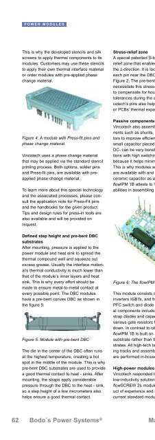
Figure 4: A module with Press-fit pins and<br />
phase change material<br />
Vincotech uses a phase change material<br />
that may be applied via the standard stencil<br />
printing process. Both options, solder pins<br />
and Press-fit pins, are available with preapplied<br />
phase change material.<br />
To learn more about this special technology<br />
and the associated processes, please consult<br />
the application note for Press-Fit pins<br />
and the handbooks for the given product.<br />
Tips and design rules for press-in tools are<br />
also available and will be provided on<br />
request.<br />
Defined step height and pre-bent DBC<br />
substrates<br />
After mounting, pressure is applied to the<br />
power module and heat sink to spread the<br />
thermal compound well and squeeze out<br />
excess grease. Usually the interface material’s<br />
thermal conductivity is much lower than<br />
that of the module’s inner layers and heat<br />
sink. This is why every effort should be<br />
made to ensure metal-to-metal contact at<br />
every possible point. The DBC modules<br />
have a pre-bent convex DBC as shown in<br />
the figure 5.<br />
Figure 5: Module with pre-bent DBC<br />
The die in the center of the DBC often runs<br />
at the highest temperature, creating a hot<br />
spot in the middle of the module. This is why<br />
pre-bent DBC substrates are used to provide<br />
a good thermal contact to heat - sinks. After<br />
mounting, the straps apply considerable<br />
pressure through the DBC to the heat - sink,<br />
so a step height of a few micrometers also<br />
helps ensure a good thermal contact.<br />
Stress-relief zone<br />
A special patented S-bend provides a stressrelief<br />
zone that enables the pin to work in<br />
the z-direction. It is located at the bottom of<br />
each pin near the DBC, which is illustrated in<br />
Figure 2. The pre-bent DBC substrates<br />
necessitate this stress-relief zone. It serves<br />
to compensate for housing and application<br />
tolerances during the assembly process. Vincotech’s<br />
pins also help control for heat sinks<br />
or PCBs’ thermal expansion.<br />
Passive components assembly<br />
Vincotech also assembles passive components<br />
such as shunts, resistors, and capacitors<br />
to improve efficiency and flexibility. A<br />
small capacitor placed between DC+ and<br />
DC- can be very beneficial in some applications<br />
with high switching frequencies<br />
because it helps minimize the current loop.<br />
This is why modules such as the H-Bridge<br />
are available with and without a built-in<br />
ceramic capacitor as a standard feature. The<br />
flowIPM 1B attests to Vincotech’s manifold<br />
abilities in assembling passive components.<br />
Figure 6: The flowIPM 1B module<br />
This module consists of rectifier diodes,<br />
inverters IGBTs, and freewheeling diodes; a<br />
PFC switch and diode are optional. Additional<br />
components include the driver IC, bootstrap<br />
diodes and capacitors, shunts, and<br />
various gate resistors for powering up and<br />
down. In contrast to other modules, the<br />
flowIPM 1B is built on a standard ceramic<br />
substrate rather than the usual DBC substrates.<br />
All high-tech tasks such as structuring<br />
tracks and assembling semiconductors<br />
are performed in-house.<br />
High-power modules<br />
Vincotech responded to growing demand for<br />
low-inductivity solutions by developing the<br />
flowSCREW 2s modules. They are the product<br />
of experience and insight gained with the<br />
current standard modules and their underly-<br />
ing technologies. The flowSCREW 2s is the<br />
first module on the market suitable for IGBTs<br />
with high switching speeds. Designed to<br />
reduce switching losses and make paralleling<br />
much easier, these modules afford<br />
designers unprecedented opportunities to<br />
minimize applications.<br />
Figure 7: Three flowSCREW 2s modules<br />
connected via a common PCB<br />
A small added multilayer PCB is sandwiched<br />
between the two DBC substrates to reduce<br />
stray inductance to 7 nH.<br />
The latest package is the flowSCREW 4w<br />
module. Engineered to achieve the greatest<br />
flexibility and efficiency, it cuts stray inductance<br />
to less than 5 nH, regardless of the<br />
integrated topology. Pins may be positioned<br />
flexibly along the main path of a large multilayer<br />
PCB leading to the screw terminals.<br />
Two base plates split one large system with<br />
a given coefficient of thermal expansion into<br />
two independent systems. This serves to<br />
make solder layers far more reliable. The<br />
module can accommodate many topologies<br />
including rectifiers, half-bridges, six-packs,<br />
and NPCs, to name just a few of the most<br />
important. It is the module of choice for<br />
solar, UPS, and other applications demanding<br />
highest efficiency. With 600 A chip current<br />
implemented in a mixed-voltage NPC<br />
topology, it supports applications up to 250<br />
kW.<br />
Conclusion:<br />
Designers in search of utmost efficiency and<br />
reliability for their applications will find the<br />
features and benefits they seek in Vincotech<br />
modules. Designed for a power range from<br />
500 to 1700 V and from 4 to 600 A, these<br />
power modules feature a variety of topologies<br />
and technologies to satisfy the needs of<br />
the most diverse applications.<br />
www.vincotech.com<br />
62 Bodo´s <strong>Power</strong> Systems ® May <strong>2011</strong> www.bodospower.com