the university of texas at arlington autonomous vehicle laboratory
the university of texas at arlington autonomous vehicle laboratory
the university of texas at arlington autonomous vehicle laboratory

You also want an ePaper? Increase the reach of your titles
YUMPU automatically turns print PDFs into web optimized ePapers that Google loves.
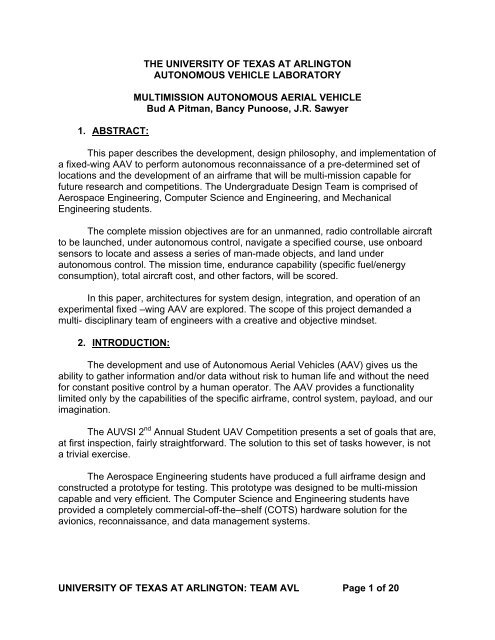
1. ABSTRACT:THE UNIVERSITY OF TEXAS AT ARLINGTONAUTONOMOUS VEHICLE LABORATORYMULTIMISSION AUTONOMOUS AERIAL VEHICLEBud A Pitman, Bancy Punoose, J.R. SawyerThis paper describes <strong>the</strong> development, design philosophy, and implement<strong>at</strong>ion <strong>of</strong>a fixed-wing AAV to perform <strong>autonomous</strong> reconnaissance <strong>of</strong> a pre-determined set <strong>of</strong>loc<strong>at</strong>ions and <strong>the</strong> development <strong>of</strong> an airframe th<strong>at</strong> will be multi-mission capable forfuture research and competitions. The Undergradu<strong>at</strong>e Design Team is comprised <strong>of</strong>Aerospace Engineering, Computer Science and Engineering, and MechanicalEngineering students.The complete mission objectives are for an unmanned, radio controllable aircraftto be launched, under <strong>autonomous</strong> control, navig<strong>at</strong>e a specified course, use onboardsensors to loc<strong>at</strong>e and assess a series <strong>of</strong> man-made objects, and land under<strong>autonomous</strong> control. The mission time, endurance capability (specific fuel/energyconsumption), total aircraft cost, and o<strong>the</strong>r factors, will be scored.In this paper, architectures for system design, integr<strong>at</strong>ion, and oper<strong>at</strong>ion <strong>of</strong> anexperimental fixed –wing AAV are explored. The scope <strong>of</strong> this project demanded amulti- disciplinary team <strong>of</strong> engineers with a cre<strong>at</strong>ive and objective mindset.2. INTRODUCTION:The development and use <strong>of</strong> Autonomous Aerial Vehicles (AAV) gives us <strong>the</strong>ability to ga<strong>the</strong>r inform<strong>at</strong>ion and/or d<strong>at</strong>a without risk to human life and without <strong>the</strong> needfor constant positive control by a human oper<strong>at</strong>or. The AAV provides a functionalitylimited only by <strong>the</strong> capabilities <strong>of</strong> <strong>the</strong> specific airframe, control system, payload, and ourimagin<strong>at</strong>ion.The AUVSI 2 nd Annual Student UAV Competition presents a set <strong>of</strong> goals th<strong>at</strong> are,<strong>at</strong> first inspection, fairly straightforward. The solution to this set <strong>of</strong> tasks however, is nota trivial exercise.The Aerospace Engineering students have produced a full airframe design andconstructed a prototype for testing. This prototype was designed to be multi-missioncapable and very efficient. The Computer Science and Engineering students haveprovided a completely commercial-<strong>of</strong>f-<strong>the</strong>–shelf (COTS) hardware solution for <strong>the</strong>avionics, reconnaissance, and d<strong>at</strong>a management systems.UNIVERSITY OF TEXAS AT ARLINGTON: TEAM AVL Page 1 <strong>of</strong> 20
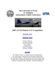
3. AIR VEHICLE DESCRIPTION:a. Design:Figure 1: UTA Team AVL- 001The design was completed using Computer Aided Design (CAD) tools,traditional methods <strong>of</strong> calcul<strong>at</strong>ion, and modeling to produce an airframe th<strong>at</strong>will have reliable and easily predictable flight characteristics. Construction <strong>of</strong><strong>the</strong> airframe mand<strong>at</strong>ed <strong>the</strong> use <strong>of</strong> composite m<strong>at</strong>erials and techniques tominimize airframe weight.The design focused on implementing well-defined characteristics <strong>of</strong> aconventional airplane to enable multi-mission multi role capabilities. Wing, tail,and fuselage will be placed in <strong>the</strong> positions found on a conventional airplane,i.e., no flying wing or canard configur<strong>at</strong>ions were used.Initial design parameters provided by <strong>the</strong> CSE team are as follows1. Mission Dur<strong>at</strong>ion: 40 minutes2. Take-Off and Landing: 100 ft. with no obstacle.3. Design <strong>vehicle</strong> Take-Off weight: 35 lbs. max4. This is no minimum or maximum speed.5. Flight Altitude: Minimum 50 ft. AGL Maximum 400 ft. AGLTable 1: Characteristics <strong>of</strong> UTA AVL and Similar AircraftUTA AVL Pred<strong>at</strong>or PioneerCruise Speed (mph) 35 104 65Max Speed (mph) 90 140 115Cruise Altitude (ft) 300 11000 26000Max Ceiling (ft) 11000 15000 40000Max T-O Weight (lbs) 35 2100 450Empty Weight (lbs) 23 700 75Range (mi) 5 500 114T-O Distance (ft) 100 5000 2000Landing Distance (ft) 100 5000 2000Wing Loading (lbs/ft 2 ) 2 18 12UNIVERSITY OF TEXAS AT ARLINGTON: TEAM AVL Page 2 <strong>of</strong> 20
Figure 2: Carbon Tube Install<strong>at</strong>ionFigure 3: Hot Wire Cut FoamIn order to have detachable wings for easy transport, it was necessary tobisect <strong>the</strong> full wing (see figure 3) and join <strong>the</strong> two wings to <strong>the</strong> fuselage. Toaccomplish this, we needed to cut two holes on <strong>the</strong> roots <strong>of</strong> each wing halfand insert wing socks in order for <strong>the</strong> wing tube to be slide in and out easily.(See figure 2). The wings were joined to <strong>the</strong> fuselage by passing two longercarbon wing tubes with slightly smaller diameters through <strong>the</strong> fuselage andinto <strong>the</strong> carbon sleeves in both wings. This provides us with a very strongwing th<strong>at</strong> can be detached for storage and transport.e. Manufacturing <strong>the</strong> Fuselage:The manufacture <strong>of</strong> <strong>the</strong> fuselage may have been <strong>the</strong> most difficultconstruction task in comparison to <strong>the</strong> rest <strong>of</strong> <strong>the</strong> aircraft. The fuselage ismade <strong>of</strong> paper honeycomb m<strong>at</strong>erial sandwiched between two layers <strong>of</strong>fiberglass. The use <strong>of</strong> <strong>the</strong>se m<strong>at</strong>erials ensured an exceeding strong, durable,and light fuselage.To manufacture multiple units, we decided to make a mold in <strong>the</strong> shape <strong>of</strong><strong>the</strong> fuselage so every fuselage th<strong>at</strong> we produce would have exactly <strong>the</strong> sameouter dimensions and smooth finish. To make a mold, a plug in <strong>the</strong> exactshape <strong>of</strong> <strong>the</strong> fuselage was needed. There were two ways we consideredmaking <strong>the</strong> plug. At first, we explored <strong>the</strong> option <strong>of</strong> buying machineablemedia and using a computerized numerical controlled (CNC) milling machineto mill out <strong>the</strong> fuselage shape and covering it with wax-release. Unfortun<strong>at</strong>ely,when we did a cost analysis we found th<strong>at</strong> it would cost us over $ 500: $300for <strong>the</strong> m<strong>at</strong>erial and $200 for shipping. Due to budget constraints, we decidedto do it in house using <strong>the</strong> method described below.UNIVERSITY OF TEXAS AT ARLINGTON: TEAM AVL Page 4 <strong>of</strong> 20
f. Making <strong>the</strong> Mold:Using <strong>the</strong> dimensions from <strong>the</strong> CAD-drawings, we printed out 20 crosssectionalshapes on to paper, glued <strong>the</strong>m on to fiberboard, and cut <strong>the</strong> shapeout <strong>of</strong> <strong>the</strong> fiberboard.Figure 4: CAD Fuse Cross-SectionFigure 5: Block Foam Templ<strong>at</strong>eWe <strong>the</strong>n cut square blocks <strong>of</strong> blue foam slightly larger than <strong>the</strong> sectionaltempl<strong>at</strong>es. The foam and <strong>the</strong> templ<strong>at</strong>es were <strong>the</strong>n glued toge<strong>the</strong>r. The foamwas cut to <strong>the</strong> shape <strong>of</strong> <strong>the</strong> templ<strong>at</strong>e using hot wire.Figure 6: Fuselage Foam PlugFigure 7: Positive <strong>of</strong> FuselageNext, all <strong>the</strong> foam sections were reassembled into <strong>the</strong> shape <strong>of</strong> <strong>the</strong>fuselage and covered with gypsum cement. The fuselage plug was <strong>the</strong>nsanded smooth. Next <strong>the</strong> mold was divided into two halves with fiberboard t<strong>of</strong>acilit<strong>at</strong>e forming <strong>the</strong> actual fuselage mold.We prepared <strong>the</strong> plug by applying two co<strong>at</strong>s <strong>of</strong> poly vinyl and two co<strong>at</strong>s <strong>of</strong>wax release agent. Then we applied epoxy resin to <strong>the</strong> surface followed bythree layers <strong>of</strong> 4 oz. fiberglass.UNIVERSITY OF TEXAS AT ARLINGTON: TEAM AVL Page 5 <strong>of</strong> 20
Figure 12: Vacuum Bagged MoldsFigure 13: Fuselage Exteriorh. Manufacturing <strong>the</strong> Vertical and Horizontal Tail Surfaces:Like <strong>the</strong> wings, <strong>the</strong> tail surfaces were also cut from foam. Shaped balsawood was added to <strong>the</strong> trailing edge <strong>of</strong> <strong>the</strong> surface for strength. The tailsurfaces were <strong>the</strong>n covered with two layers <strong>of</strong> fiberglass cloth and epoxy.After curing, <strong>the</strong> control surfaces (rudders and elev<strong>at</strong>ors) were cut from <strong>the</strong>existing surfaces. The vertical surfaces were <strong>at</strong>tached to <strong>the</strong> horizontalsurfaces using epoxy resin and carbon fiber rods. The entire tail surfaceassembly was <strong>at</strong>tached to <strong>the</strong> fuselage and wings using twin tail booms. Thebooms are four foot long carbon fiber tubes with 1 ½ inch diameter.Figure 14: Control SurfacesFigure 15: Diesel Test Standi. Engine:In order to meet <strong>the</strong> requirements <strong>of</strong> reliability, power and efficiency, anengine with <strong>at</strong> least 4 HP was needed. Weight reduction <strong>of</strong> <strong>the</strong> engine andability to get enough horsepower mand<strong>at</strong>ed a clever solution. The enginechosen was a Supertigre G-3000 with a diesel conversion kit. The converteddiesel engine produces 20 pounds <strong>of</strong> thrust with <strong>the</strong> engine weighing in <strong>at</strong>only three pounds.UNIVERSITY OF TEXAS AT ARLINGTON: TEAM AVL Page 7 <strong>of</strong> 20
j. Testing:Testing <strong>the</strong> aircraft is a continuous evolution as new fe<strong>at</strong>ures are broughtonline. The testing <strong>of</strong> <strong>the</strong> aircraft’s main control surfaces and sensors will beconducted in parts: bench, piloted, semi-<strong>autonomous</strong>, and <strong>autonomous</strong> flight.The bench testing ensures th<strong>at</strong> each control actu<strong>at</strong>ed properly, had <strong>the</strong>correct degree <strong>of</strong> motion, and torque to accomplish <strong>the</strong> task in flight. Theabove ground level (AGL) sensor, global positioning system (GPS), andinertial navig<strong>at</strong>ion system (INS) were also calibr<strong>at</strong>ed and tested on <strong>the</strong> benchto ensure nominal behavior.In order to ensure safety and facilit<strong>at</strong>e repetitive calibr<strong>at</strong>ion, flight testcards were developed. The flight test cards document <strong>the</strong> post-install<strong>at</strong>ioncheck lists, preflight check lists, and post-flight check lists to ensure safeoper<strong>at</strong>ion <strong>of</strong> <strong>the</strong> AAV. St<strong>at</strong>ic and flight test cards are sequentially numberedand each test must be signed <strong>of</strong>f by a represent<strong>at</strong>ive member <strong>of</strong> <strong>the</strong> Airframeteam and CSE team.4. GROUND CONTROL STATION (GCS) DESCRIPTION:a. Overview:The GCS consists <strong>of</strong> three entities; The Avionics GCS, D<strong>at</strong>a CollectionSt<strong>at</strong>ion and Pilot Oper<strong>at</strong>ed Remote Control Transmitter. The division <strong>of</strong>Avionics GCS and D<strong>at</strong>a Collection St<strong>at</strong>ion was done to avoid any conflict with<strong>the</strong> mission objectives, safe positive control, and <strong>autonomous</strong> oper<strong>at</strong>ion <strong>of</strong> <strong>the</strong>AAV. The AAV will be oper<strong>at</strong>ing in a totally <strong>autonomous</strong> mode from take<strong>of</strong>f tolanding. In flight, <strong>the</strong> AAV will communic<strong>at</strong>e, via radio frequencytransmitters/receivers, with two discrete computer systems using 900 MHzband radio modems and 2.4 GHz band Wireless Network Cards. There willalso be <strong>the</strong> 72 MHz band Pilot Oper<strong>at</strong>ed Remote Control Transmitter.b. Avionics Ground Control St<strong>at</strong>ion:Communic<strong>at</strong>ion with <strong>the</strong> <strong>autonomous</strong> avionic suite will be performed intwo ways. If <strong>the</strong> AAV is on <strong>the</strong> ground and in a safe configur<strong>at</strong>ion,communic<strong>at</strong>ion and d<strong>at</strong>a will be handled with a hardwire RS232 connectionbetween <strong>the</strong> Micropilot MP2028g Autonomous Control System (Described in<strong>the</strong> Section 5: Payload Description) and GCS notebook computer. If <strong>the</strong> AAVis in flight, communic<strong>at</strong>ion between MP2028g and notebook computer ishandled over an identical RS232 connection with <strong>the</strong> addition <strong>of</strong> 900 MHz,9600 baud, radio modems.UNIVERSITY OF TEXAS AT ARLINGTON: TEAM AVL Page 8 <strong>of</strong> 20
c. Using MP2028g HORIZONmp S<strong>of</strong>tware:The MP2028g includes <strong>the</strong> HORIZONmp for mission cre<strong>at</strong>ion, parameteradjustment, flight monitoring and mission simul<strong>at</strong>ion. The HORIZONmps<strong>of</strong>tware <strong>of</strong>fers a GUI interface for communic<strong>at</strong>ing with <strong>the</strong> MP2028g. It actsas a setup tool for configur<strong>at</strong>ion <strong>of</strong> <strong>the</strong> MP2028g. Its main function is to allow<strong>the</strong> user to observe and interact with <strong>the</strong>ir UAV while it is in flight or on <strong>the</strong>ground via <strong>the</strong> RS232 cable provided by MicroPilot. In flight communic<strong>at</strong>ion isdone via 900 MHz radio modems.Figure 16: PID Adjustment ExampleFigure 17: Active GCS Exampled. D<strong>at</strong>a Collection St<strong>at</strong>ion:An additional notebook computer is used for <strong>autonomous</strong> d<strong>at</strong>a download<strong>of</strong> ga<strong>the</strong>red d<strong>at</strong>a from <strong>the</strong> AAV. The notebook computer is connected to <strong>the</strong> AAVusing a 2.4 GHz WI-FI wireless network system. The single board PC on board<strong>the</strong> AAV autom<strong>at</strong>ically will send raw and processed images to <strong>the</strong> D<strong>at</strong>a CollectionNotebook via an omni directional antenna on <strong>the</strong> AAV and a hand-helddirectional antenna on <strong>the</strong> ground. The d<strong>at</strong>a may <strong>the</strong>n be processed fur<strong>the</strong>r,printed, or transferred <strong>at</strong> will.UNIVERSITY OF TEXAS AT ARLINGTON: TEAM AVL Page 9 <strong>of</strong> 20
4 MP CAMERAKODAK DX64403V INTERNALPOWERSBPC POWERBATTERYMP2028gPOWERGPS ANTENNA350 MHz SINGLE BOARD PCPC104 BUSVERSALOGICEPM-CPU-10M JAGUARUSB 1.1, PCMCIA, RS232MP 2028gMICROPILOTACOUSTIC AGLSENSOR BOARDCAMERASTABILIZATIONGYRO ANDSERVOSERVO CONTROLBOARD5 ≤ NUM SERVOS ≤ 32STABILIZERGYRO POWERSERVO POWERBATTERYRADIOCONTROL RXRADIO MODEM900 MHzWIFI PCMCIACARD 2.4 GHzRADIOCONTROL TXGCSLAPTOP PCDATA RETRIEVALLAPTOP PCOEM SUPPLIEDUSB 1.1RS 232PCMCIARF WIRELESSFigure 18: Autonomous Aerial Recon Vehicle: Payload OverviewUNIVERSITY OF TEXAS AT ARLINGTON: TEAM AVL Page 10 <strong>of</strong> 20
5. PAYLOAD DESCRIPTION:Due to generous contributions from MicroPilot <strong>of</strong> Canada with <strong>the</strong>ir autopilotavionics and VersaLogic <strong>of</strong> California with <strong>the</strong>ir Single Board Computer (SBPC), it waspossible to construct a fairly high-level s<strong>of</strong>tware systems architecture running Java on<strong>the</strong> Linux Oper<strong>at</strong>ing System. The s<strong>of</strong>tware system on <strong>the</strong> SBPC is a central part <strong>of</strong> <strong>the</strong>mission package onboard <strong>the</strong> AAV.The architecture was chosen because <strong>of</strong> it modularity. The entire mission specificpackage lies between one RS232 d<strong>at</strong>a line. This line is <strong>the</strong> connection between <strong>the</strong>MicroPilot MP2028g and <strong>the</strong> 900 MHz telemetry radio modem. The entire AUVSIpayload may be disconnected from this single d<strong>at</strong>a p<strong>at</strong>h and replaced with a completelydifferent payload.The SBPC on <strong>the</strong> AAV serves as an inform<strong>at</strong>ion conduit and inform<strong>at</strong>ion storagedevice via this RS232 d<strong>at</strong>a p<strong>at</strong>h. It monitors <strong>the</strong> MicroPilot’s raw d<strong>at</strong>a being sent to <strong>the</strong>ground st<strong>at</strong>ion and intercepts <strong>the</strong> GPS loc<strong>at</strong>ion and <strong>at</strong>titude <strong>of</strong> <strong>the</strong> aircraft. The Cmaintains a list <strong>of</strong> targets and <strong>the</strong>ir GPS loc<strong>at</strong>ions along with <strong>the</strong> most current GPSloc<strong>at</strong>ion <strong>of</strong> <strong>the</strong> aircraft and <strong>the</strong> <strong>at</strong>titude <strong>of</strong> <strong>the</strong> aircraft.When <strong>the</strong> SBPC detects th<strong>at</strong> <strong>the</strong> AAV is over a target, it will send a command to<strong>the</strong> camera to take a picture <strong>of</strong> <strong>the</strong> target. It will <strong>the</strong>n download <strong>the</strong> image into <strong>the</strong> SBPCmemory from <strong>the</strong> camera. In addition, <strong>the</strong> onboard computer will write a file with <strong>the</strong><strong>at</strong>titude <strong>of</strong> <strong>the</strong> aircraft <strong>at</strong> <strong>the</strong> time <strong>the</strong> picture was taken. The SBPC will <strong>the</strong>n download<strong>the</strong> image and <strong>at</strong>titude file to <strong>the</strong> ground st<strong>at</strong>ion via WI-FI network card.When a different mission is design<strong>at</strong>ed for this AAV <strong>the</strong> payload may beconfigured <strong>at</strong> will. The modularity and reusability <strong>of</strong> <strong>the</strong> AAV was a major designphilosophy. The modularity <strong>of</strong> <strong>the</strong> payload lends itself directly to safety and reliability. If<strong>the</strong> mission package should fail, <strong>the</strong> AAV will not become unsafe. The programming <strong>of</strong><strong>the</strong> MP2028g will remain intact as will <strong>the</strong> ability to take RC manual control.a. Payload Hardware Composition:1. VersaLogic EPM-CPU-10M Jaguar 350 MHz Single Board PCWith PC104 Bus2. Kodak DX6440 4 Mega Pixel Camera3. Camera Stabiliz<strong>at</strong>ion Gyroscope And Servo4. MP 2028g MicroPilot Autonomous Control System5. MicroPilot Acoustic Altimeter6. MaxStream 9XStream 900 MHz Radio Modem7. ORiNOCO 11B/G PC Card IEEE 802.11 B/GUNIVERSITY OF TEXAS AT ARLINGTON: TEAM AVL Page 11 <strong>of</strong> 20
. VersaLogic Jaguar 350 MHz Single Board PC (SBPC) Description:The Jaguar Pentium III Single Board Personal Computer (SBPC) waschosen due to its known reliability. The PC 104 bus enables expansion limitedonly by weight and power requirements.Figure 18: RF Shielded EnclosureFigure 19: PC Install<strong>at</strong>ionThe enclosure for <strong>the</strong> PC and camera is made <strong>of</strong> .25” fiberglass coveredhoneycomb composite. The exterior <strong>of</strong> <strong>the</strong> PC/Camera enclosure is lamin<strong>at</strong>edin aluminum and copper tape with conductive adhesive. The enclosure isdesigned to reflect all RF interference away from all o<strong>the</strong>r components on <strong>the</strong>AAV thus avoiding any possibility <strong>of</strong> interference with <strong>the</strong> Avionics as well as<strong>the</strong> GPS receiver. The SBPC is <strong>the</strong> single largest source <strong>of</strong> RF interferenceand no interference can be allowed. RF energy will be reflected forward anddown from <strong>the</strong> AAV.The Jaguar was designed for projects requiring fast processing, compactsize, flexible memory options, high reliability, and long-term availability. It als<strong>of</strong>e<strong>at</strong>ures high speed rendering, with standard CRT interface, DiskOnChipsupport, 128 KB level 2 cache, w<strong>at</strong>chdog timer, and Vcc sensing reset circuit.Standard I/O ports include floppy, keyboard, PS/2 mouse, PCI-based IDE,LPT, and two COM ports (one RS-232/422/485 selectable).The high reliability design and construction <strong>of</strong> SBPC fe<strong>at</strong>ures TransientVoltage Suppressors (TVS) on user I/O ports for enhanced ESD protection,l<strong>at</strong>ching I/O connectors, low-EMI clock gener<strong>at</strong>ion, and self-resetting fuse on<strong>the</strong> 5V supply to <strong>the</strong> keyboard, mouse, and USB ports.The Jaguar delivers full Socket 370 comp<strong>at</strong>ibility with PC/104-Plusinterconnection ability. Each board is subjected to environmental stressscreening and complete functional testing.UNIVERSITY OF TEXAS AT ARLINGTON: TEAM AVL Page 12 <strong>of</strong> 20
c. Kodak DX6440 4 Mega Pixel Camera and Optics:The camera and control system was chosen for image quality, ease <strong>of</strong>oper<strong>at</strong>ion, redundant d<strong>at</strong>a storage, and Java Picture Taking Protocolcomp<strong>at</strong>ibility. The camera is mounted on a free pitch axis mount th<strong>at</strong> iscontrolled by a heading hold gyroscope and servo normally used for RCmodel helicopters. The gyro ensures, while <strong>the</strong> wings are level, any pitch <strong>of</strong><strong>the</strong> AAV will not affect <strong>the</strong> cameras orient<strong>at</strong>ion perpendicular to <strong>the</strong> ground. AGPS overlay for every photo can be available for ease in identific<strong>at</strong>ion andloc<strong>at</strong>ion <strong>of</strong> each pixel in <strong>the</strong> image.The use <strong>of</strong> a wide-angle lens <strong>at</strong>tachment is available also for low-altitudemission requirements. The image processing and GPS overlay can becalcul<strong>at</strong>ed for <strong>the</strong> wide angle lens as well.d. MP2028g Autonomous Control System and Avionics:The MP2028 g weighs only 28 grams with dimensions <strong>of</strong> 10 cm by 4 cm.The MP2028 g includes <strong>the</strong> HORIZON mp ground control s<strong>of</strong>tware. This unitwas provided to <strong>the</strong> team by MicroPilot. Extensive d<strong>at</strong>a logging and manualoverrides are also supported, as is a highly functional command buffer. Allfeedback loop gains and flight parameters are user-programmable andfeedback loops are adjustable in-flight. The MP2028g also includes <strong>the</strong>HORIZONmp for mission cre<strong>at</strong>ion, parameter adjustment, flight monitoringand mission simul<strong>at</strong>ion.e. Acoustic Altimeter:Figure 21: MP2028g LayoutThe AGL board is an ultrasonic altimeter th<strong>at</strong> provides high-resolutionaltitude inform<strong>at</strong>ion up to an altitude <strong>of</strong> 16 feet and is required for <strong>autonomous</strong>take<strong>of</strong>f and landing. By default, <strong>the</strong> MP2028g expects an AGL board. Theultrasonic transducer is mounted facing down on <strong>the</strong> bottom <strong>of</strong> <strong>the</strong> fuselage.The cable between <strong>the</strong> transducer and <strong>the</strong> board is shielded coax.UNIVERSITY OF TEXAS AT ARLINGTON: TEAM AVL Page 13 <strong>of</strong> 20
f. Camera Stabiliz<strong>at</strong>ion Gyroscope:Due to <strong>the</strong> effects <strong>of</strong> wind during flight; it was necessary to activelystabilize <strong>the</strong> camera on <strong>the</strong> aircraft in order to produce quality aerialphotographs. The gyroscope is a standard helicopter stability gyroscopemade by CSM model CSM200 controlling a servo model JR4735.g. 9XStream is MaxStream Radio Modems:The 9XStream is MaxStream's longest range, low power wireless OEMmodule. MaxStream radios were chosen for <strong>the</strong>ir known reliability and longrange. During testing <strong>the</strong> modems communic<strong>at</strong>ed reliably <strong>at</strong> ranges <strong>of</strong> 5miles. Receiver sensitivity is a measure <strong>of</strong> <strong>the</strong> weakest signal a radio is ableto detect and demodul<strong>at</strong>e. Superior receiver sensitivity can overcome many <strong>of</strong><strong>the</strong> challenges inherent to RF communic<strong>at</strong>ion systems such as signal<strong>at</strong>tenu<strong>at</strong>ion (degrad<strong>at</strong>ion). Simply put, MaxStream allows integr<strong>at</strong>ors to covermore ground with fewer radios.Every -6 dB <strong>of</strong> receiver sensitivity gained doubles <strong>the</strong> range (outdoor RFline-<strong>of</strong>-sight environments. -10 dB doubles <strong>the</strong> range in indoor/urbanenvironments. MaxStream wireless modems achieve up to 8 times <strong>the</strong> range<strong>of</strong> competing modems.h. Silver ORiNOCO 802.11b/g PC Card Wi-Fi Networking System:The ORiNOCO 802.11b/g ComboCard is a high-performance wirelessLAN adapter card th<strong>at</strong> complies with <strong>the</strong> 802.11b and 802.11g wirelessstandards. This card was selected for its reliability and <strong>the</strong> availability <strong>of</strong> anexternal antenna connection. This connection provides access to an omnidirectionalantenna providing broad coverage and 5.5 dBi gain.The card is interoperable with IEEE 802.11a, 802.11b and 802.11gequipment from any manufacturer.i. Radio Control Receiver:The remote control transmitter and receiver is a JR XP8103H transmitterand NER-649S PCM receiver. These were chosen for <strong>the</strong>ir reliability,familiarity <strong>of</strong> <strong>the</strong> design<strong>at</strong>ed pilots <strong>of</strong> <strong>the</strong> AAV, and quality. The computersystem used in <strong>the</strong> XP8103 is <strong>the</strong> easiest to understand, easiest to oper<strong>at</strong>emulti-function 8-channel computer radio. The large LCD display provideseasy-to-read graphics and <strong>the</strong> control sticks <strong>of</strong>fer adjustable spring tensionand length. The transmitter provides autom<strong>at</strong>ic fail-safe and inform<strong>at</strong>ionupd<strong>at</strong>e in PCM mode when fail-safe is used and Direct Servo Control (DSC)permits oper<strong>at</strong>ion <strong>of</strong> all <strong>the</strong> controls and servos while also making transferableall d<strong>at</strong>a between transmitters without gener<strong>at</strong>ing a radio signal.UNIVERSITY OF TEXAS AT ARLINGTON: TEAM AVL Page 14 <strong>of</strong> 20
6. DATA LINK DESCRIPTION:The AAV’s d<strong>at</strong>a link is comprised <strong>of</strong> two key components: EIA-232 Serialconnection via <strong>the</strong> MaxStream Radio Modems and a TCP/IP network connection via <strong>the</strong>ORiNOCO Silver 802.11b/g PC Card. The MaxStream modems oper<strong>at</strong>e <strong>at</strong> 900 MHzand afford a <strong>the</strong>oretical range <strong>of</strong> five kilometers. The ORiNOCO PC Card oper<strong>at</strong>ing <strong>at</strong>2.4 GHz and utilizing <strong>the</strong> 802.11B protocols has a one kilometer range. This range isextended to 3 kilometers with <strong>the</strong> use <strong>of</strong> an omni directional antenna on board <strong>the</strong> AAVand a directional antenna <strong>at</strong> <strong>the</strong> GCS.The serial connection is dedic<strong>at</strong>ed to <strong>the</strong> raw d<strong>at</strong>a stream <strong>of</strong> <strong>the</strong> MicroPilotMP2028 g autopilot subsystem. The raw d<strong>at</strong>a stream contains aircraft GPS loc<strong>at</strong>ion, INSinform<strong>at</strong>ion, and all current MicroPilot inform<strong>at</strong>ion. The inform<strong>at</strong>ion is fed to <strong>the</strong>HORIZON s<strong>of</strong>tware on <strong>the</strong> ground via <strong>the</strong> radio modems, to monitor AAV oper<strong>at</strong>ion.The network connection is dedic<strong>at</strong>ed to download <strong>of</strong> images from <strong>the</strong> onboardKodak camera. In addition, <strong>at</strong>titude files corresponding to each image takenaccompany each picture. This link, in <strong>the</strong> future, may support more unique telemetry as<strong>the</strong> system evolves.The bands in oper<strong>at</strong>ion and discrete d<strong>at</strong>a p<strong>at</strong>hs for critical and non-criticalinform<strong>at</strong>ion lead to system reliability and safety. One system cannot interfere withano<strong>the</strong>r and lead to a failure.7. METHOD OF AUTONOMY:The <strong>autonomous</strong> flight is governed by <strong>the</strong> MicroPilot MP2028 g autopilot subsystem.The MicroPilot uses onboard sensor d<strong>at</strong>a from GPS, INS, sonic and pressure altimeter,and airspeed sensor to model <strong>the</strong> aircrafts <strong>at</strong>titude in flight. Using <strong>the</strong> sensor d<strong>at</strong>a andcoupled with Proportional, Integral, Deriv<strong>at</strong>ive (PID) control loops, <strong>the</strong> MicroPilotcontrols <strong>the</strong> actu<strong>at</strong>ion <strong>of</strong> <strong>the</strong> control surfaces. The PID loops control <strong>the</strong> upd<strong>at</strong>e <strong>of</strong>signals to <strong>the</strong> servos controlling <strong>the</strong> surfaces.On a macro level, <strong>the</strong> MicroPilot embedded flight s<strong>of</strong>tware implements <strong>the</strong> followingflight rules: airspeed hold, altitude hold, turn coordin<strong>at</strong>ion, GPS navig<strong>at</strong>ion as well as<strong>autonomous</strong> launch and recovery. The aircraft follows a sequential flight plan th<strong>at</strong>includes aircraft-specific parameters and capabilities so <strong>the</strong> flight s<strong>of</strong>tware nei<strong>the</strong>runderestim<strong>at</strong>es nor overestim<strong>at</strong>es <strong>the</strong> capabilities <strong>of</strong> <strong>the</strong> aircraft being controlled.UNIVERSITY OF TEXAS AT ARLINGTON: TEAM AVL Page 15 <strong>of</strong> 20
8. SAFETY CONSIDERATIONS:This project was begun in earnest in February <strong>of</strong> 2004 and safety was <strong>of</strong>paramount concern from <strong>the</strong> beginning <strong>of</strong> <strong>the</strong> project and through its completion. Aproject involving compression <strong>of</strong> time and rapid development could lead to errors injudgment and missed opportunities. This was addressed <strong>at</strong> <strong>the</strong> beginning <strong>of</strong> <strong>the</strong> projectand throughout <strong>the</strong> daily oper<strong>at</strong>ion <strong>of</strong> <strong>the</strong> equipment in Autonomous Vehicle Labor<strong>at</strong>ory.The students involved were pr<strong>of</strong>essional and, as <strong>the</strong> project progressed, safetyconcerns regarding reliability <strong>of</strong> <strong>the</strong> system were continuously upd<strong>at</strong>ed. The Mechanicaland Aerospace Engineering (MAE) team designed a very robust and reliable AAV. TheComputer Science and Engineering (CSE) team concentr<strong>at</strong>ed on <strong>the</strong> mission package,thus ensuring modularity and fault tolerance.The airframe has been engineered as a very strong and light airframe. Them<strong>at</strong>erials and construction method used were chosen for known confidence in qualityand known capabilities. The airframe has been designed to perform with high stabilityand docile characteristics.The hardware in <strong>the</strong> mission payload and avionics involve many types <strong>of</strong> hardware,power requirements, and radio frequency gener<strong>at</strong>ors and tolerances. The payload andavionics will be shielded and tested <strong>at</strong> all points in implement<strong>at</strong>ion to preventinterference and failure. Vibr<strong>at</strong>ion tolerances were also accounted for by isol<strong>at</strong>ion <strong>of</strong>safety critical and mission-critical items. A full AAV system checklist was written andfollowed for every change in <strong>the</strong> AAV configur<strong>at</strong>ion. This checklist will be run after anychange in ei<strong>the</strong>r airframe or electronic implement<strong>at</strong>ion.All payload devices were designed and/or implemented with <strong>the</strong>ir own discretepower supplies and thus will not be co-dependent upon <strong>the</strong> power supplies <strong>of</strong> o<strong>the</strong>rdevices. This avoids any potential power problems, interference problems, and protects<strong>the</strong> oper<strong>at</strong>ion <strong>of</strong> <strong>the</strong> MicroPilot. The oper<strong>at</strong>ion <strong>of</strong> <strong>the</strong> MicroPilot is important. Theoper<strong>at</strong>ion <strong>of</strong> <strong>the</strong> Radio Control system however, was deemed <strong>the</strong> most important.The Radio Control system is <strong>the</strong> found<strong>at</strong>ion for fault recovery and AAV recovery if<strong>the</strong> MicroPilot should fail. The MicroPilot is second in <strong>the</strong> hierarchy <strong>of</strong> criticality. TheMicroPilot will be tested extensively for highly reliable oper<strong>at</strong>ion <strong>of</strong> <strong>the</strong> AAV andnavig<strong>at</strong>ion accuracy. The Mission Payload was specifically designed and implementedto ensure no interference with items higher in <strong>the</strong> chain <strong>of</strong> critical hardware.UNIVERSITY OF TEXAS AT ARLINGTON: TEAM AVL Page 16 <strong>of</strong> 20
9. APPENDICES:Appendix I:UAV Result Characteristics ComparisonAppendix II:Design ParametersUAV PROPOSEDUAV FINALCruise Mach No. 0.065 (35 mph) 0.0712 (54 mph)Maximum Mach No. 0.12 (90 mph) .12 (90 mph)Cruise Altitude (ft) 100 200Max. T-O Weight (lbs) 25 35Empty Weight (lbs) 15 23Range (ft) 2300 2500T-O Distance (ft) 100 132Landing Distance (ft) 100 525Payload (lbs) 10 10SPECIFICATIONAspect R<strong>at</strong>io 10.4UNITSWing Area 16.25 ft 2Wing Span 13 ftW/S 2 lb/ft 2C L max 1.2Fuselage Length 6.8 ftFuselage Diameter 1.5 ftWeight Take-Off 35 lbsWeight Landing 33 lbsTotal Viscous Drag 5 lbsC D Coefficient 0.026Engine Thrust 19 lbsT/W 0.55UNIVERSITY OF TEXAS AT ARLINGTON: TEAM AVL Page 17 <strong>of</strong> 20
Appendix III:Jaguar Single Board PC Specific<strong>at</strong>ionsModel Number: EPM-CPU-10m - Intel Celeron 350 MHz (equiv) extended temp.Accessories: Dual USB transition cable. Type I/II Compact Flash adapter. 96 MBDiskOnChip Flash module. 128 MB SDRAM module[Specific<strong>at</strong>ions are typical <strong>at</strong> 25°C with 5.0V supply unless o<strong>the</strong>rwise noted]Chipset: Intel 440BXSystem Reset: Vcc sensing, resets below 4.70V typical. W<strong>at</strong>chdog timeoutComp<strong>at</strong>ibility: PC/104, except board width; PC/104-Plus – Full compliance.Board Size: 3.95” x 3.775”Oper<strong>at</strong>ing Temper<strong>at</strong>ure: – 40° C to +75° C free air, no airflow.Bus Speed: CPU External: 66/100 MHz: PCI: PC/104: 8 MHzHumidity: Less than 95%, non-condensingPower Requirements: 5V ±5% @ 3.52A typical. 17.60 WDRAM Interface: One 144-pin SODIMM, 256 MB <strong>of</strong> 3.3V SDRAMFlash Interface: One 32-pin JEDEC DIP socket. M-Systems DiskOnChipVideo Interface: ATI Rage Mobility chip AGP interface and 4 MB integr<strong>at</strong>ed RAM. CRT,LVDS and DVO (TTL) outputs. Resolutions up to 1280x1024 with 16.7 milliondisplayable colors. Supports MPEG-2, 3-D, edge anti-aliasing, specular shading andtexture mapping.COM 1 Interface: RS-232, 16C550 comp<strong>at</strong>ible, 115K baud max.COM 2 Interface: RS-232/422/485, 16C550 comp<strong>at</strong>ible, 460K baud max.LPT Interface: Bidirectional/EPP/ECP comp<strong>at</strong>ible.USB Interface: Two user ports (1.1 protocols).PCMCIA Interface: Vadem VG-468 Chipset (register comp<strong>at</strong>ible with Intel 82365SL)PC/104; Type I, II, and III comp<strong>at</strong>ibleOper<strong>at</strong>ing Systems: LinuxBIOS: General S<strong>of</strong>tware Embedded BIOS with OEM Enhancements.Appendix IV:Kodak EasyShare DX6440 Zoom Digital Camera Specific<strong>at</strong>ionsColor: 24-bitDimensions: W: 109 mm D: 38 mm H: 64.5 mm Wt: 220 g w/b<strong>at</strong>tery and cardFile Form<strong>at</strong>: Still JPEG/EXIF v2.2Range Wide: 1.6-16.7 ft (0.5-5.1 m) f/2.4Image sensor: 1/2.5 in. interline transfer CCD, 4:3 aspect r<strong>at</strong>io, 2408 x 1758 pixelsAperture Wide: f/2.2 - f/5.6; Tele: f/4.8 - f/13Focal Length: 33 - 132 mmFocus Distance Standard Wide: 19.7 in. (50 cm) to infinityOper<strong>at</strong>ing Temper<strong>at</strong>ure: 32 to 104° F (0 to 40° C)Picture/Video Storage: 16 MB internal; SD Card 128 MB; Image Storage AutoPixel Resolution: Best 2304 x 1728 (4.0 M) pixelsLandscape: Wide: 1/2200-1/60 secNight: 1/2200 to 1/2 sec.UNIVERSITY OF TEXAS AT ARLINGTON: TEAM AVL Page 18 <strong>of</strong> 20
Appendix V:9XStream is MaxStream Radio Modems Specific<strong>at</strong>ionsConnection: Plug-and-communic<strong>at</strong>e (default mode - no configur<strong>at</strong>ion required).True peer-to-peer network (no need to configure a "Master" radio). Transparent modesupports existing s<strong>of</strong>tware applic<strong>at</strong>ions and legacy systems.D<strong>at</strong>a Handling: Addressing capabilities provide point-to-point and point-to-multipointnetworks. Uses Standard AT commands and/or fast binary commands for changingparameters. Retry and acknowledgements <strong>of</strong> packets provides guaranteed delivery <strong>of</strong>critical packets in difficult environments. 9th bit parity support (None, Even, Odd, Mark,Space)Protocol Support: N<strong>at</strong>ive RS485/422 (multi-drop bus) protocol support.Modes: Multiple low power modes including shutdown pin, cyclic sleep and serial portsleep for current consumption as low as 26 µA.Baud R<strong>at</strong>es: Host interface baud r<strong>at</strong>es from 1200 to 57600 bps.Monitoring: Signal strength register for link quality monitoring and debugging.Appendix VI:Silver ORiNOCO 802.11b/g PC Card Wi-Fi Networking System Specific<strong>at</strong>ionsBus: CardBus Type-II slot. Connector for external range extender antenna.Certific<strong>at</strong>ions & Standards: - IEEE 802.11B IEEE 802.11G IEEE 802.1xPhysical characteristics: Dimensions: 4.79 x 2.12 x 0.19Environmental Conditions:Temper<strong>at</strong>ure: 0 to 55 C, (oper<strong>at</strong>ing)Humidity: 90% non-condensing, (oper<strong>at</strong>ing) 95% non-condensing (Storage)Power description: Input Voltage: 3.3V DC 0.2V DCPorts: 1 x, radio-E<strong>the</strong>rnetProtocols Supported: Csma/CAFrequency band/bandwidth: 2400 to 2484MHZTransmission speed: 6 to 54MBPS (IEEE 802.11G) 1 to 11MBPS (IEEE 802.11B)Transmit power: 60 MW (maximum) (IEEE 802.11G) 85 MW (IEEE 802.11B)Modul<strong>at</strong>ion: - 802.11G orthogonal Frequency division modul<strong>at</strong>ion (64, QAM, 16 QAM,QPSK, BPSK) 802.11B Direct sequence spread spectrum (CCK, DQPSK, DBPSK)UNIVERSITY OF TEXAS AT ARLINGTON: TEAM AVL Page 19 <strong>of</strong> 20
Appendix VII:AAV Budget and Cost:ITEM RETAIL ACTUAL EXPLANATIONVersaLogic EPM-CPU-10 $1,225.00 $0.00 Don<strong>at</strong>ionMicroPilot MP2028g $5,000.00 $0.00 Don<strong>at</strong>ionMicroPilot - AGL Board $500.00 $0.00 Don<strong>at</strong>ion9XStream - Radio Modems $180.00 $0.00 Don<strong>at</strong>ionKodak DX6440 Camera $284.00 $284.00 Actual CostCamera Gyro and Servo $96.00 $96.00 Actual CostSilver ORiNOCO PC Card $45.00 $0.00 Don<strong>at</strong>ionRadio Control RX and TX $1,119.00 $0.00 Don<strong>at</strong>ionA/C Components andM<strong>at</strong>erial $1,200.00 $1,200.00Approx. as <strong>of</strong>15May2004Electronics and M<strong>at</strong>erialApprox. as <strong>of</strong>$360.00 $360.00Support and PowerEquipment $847.00 $847.0015May2004Approx. as <strong>of</strong>15May2004TOTALS $10,856.00 $2,787.00Approx. as <strong>of</strong>15May2004REFERENCES:Versalogic EPM-CPU-10M Jaguar Manualhttp://www.versalogic.com/Products/Manuals/MEPMCPU10.pdfKodak DX6440 Manualhttp://www.kodak.com/global/en/service/products/ekn027036.jhtmlMP 2028g MicroPilot Manualhttp://www.micropilot.com/resources/manuals/Manual-MP2028.pdfMaxStream 9XStream Manualhttp://www.maxstream.net/products/xstream/module/manual_XStream-OEM-RF-Module_v4.29.pdfORiNOCO 11B/G PC Card Manualhttp://www.proxim.com/learn/library/d<strong>at</strong>asheets/11bgpccard.pdfUNIVERSITY OF TEXAS AT ARLINGTON: TEAM AVL Page 20 <strong>of</strong> 20