PICAXE Connect Board - Solarbotics
PICAXE Connect Board - Solarbotics
PICAXE Connect Board - Solarbotics

You also want an ePaper? Increase the reach of your titles
YUMPU automatically turns print PDFs into web optimized ePapers that Google loves.
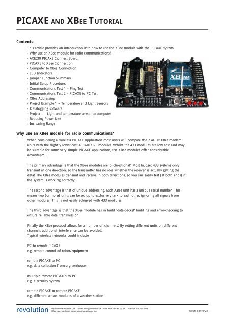
<strong>PICAXE</strong> AND XBEE TUTORIALContents:This article provides an introduction into how to use the XBee module with the <strong>PICAXE</strong> system.- Why use an XBee module for radio communications?- AXE210 <strong>PICAXE</strong> <strong>Connect</strong> <strong>Board</strong>.- <strong>PICAXE</strong> to XBee <strong>Connect</strong>ion- Computer to XBee <strong>Connect</strong>ion- LED Indicators- Jumper Function Summary- Initial Setup Procedure.- Communications Test 1 – Ping Test- Communications Test 2 – <strong>PICAXE</strong> to PC Test- XBee Addressing- Project Example 1 – Temperature and Light Sensors- Datalogging software- Project 1 – Light and temperature sensor to computer- Reducing Power Use- Increasing RangeWhy use an XBee module for radio communications?When considering a wireless <strong>PICAXE</strong> application most users will compare the 2.4GHz XBee modemunits with the slightly lower-cost 433MHz RF modules. Whilst the 433 modules are low cost and maybe suitable for some very simple <strong>PICAXE</strong> applications, the XBee modules offer considerableadvantages.The primary advantage is that the XBee modules are ‘bi-directional’. Most budget 433 systems onlytransmit in one direction, so the transmitter has no idea whether the receiver is actually getting thedata! The XBee modules transmit and receive in both directions, so you can easily test (at both ends) ifthe system is working correctly.The second advantage is that of unique addressing. Each XBee unit has a unique serial number. Thismeans two (or more) units can be set up to exclusively talk to each other, ignoring all signals fromother modules. This is not easily achieved with 433 modules.The third advantage is that the XBee module has in build ‘data-packet’ building and error-checking toensure reliable data transmission.Finally the XBee protocol allows for a number of ‘channels’. By setting different units on differentchannels additional interference can be avoided.Typical wireless networks could includePC to remote <strong>PICAXE</strong>e.g. remote control of robot/equipmentremote <strong>PICAXE</strong> to PCe.g. data collection from a greenhousemultiple remote <strong>PICAXE</strong>s to PCe.g. a security systemremote <strong>PICAXE</strong> to remote <strong>PICAXE</strong>e.g. different sensor modules of a weather stationrevolutionRevolution Education Ltd. Email: info@rev-ed.co.uk Web: www.rev-ed.co.uk Version 1.0 29/01/06XBee is a registered trademark of Maxstream Inc.AXE210_XBEE.PMD
<strong>PICAXE</strong> and the XBee Module3Computer to XBee <strong>Connect</strong>ionWhen a MAX3232 chip is inserted in the 16pin socket the XBee module is connected(via the download cable) directly to the computer serial port. Therefore data can betransmitted from/received by the computer. The XBee module can also be configuredvia use of the Programming Editor XBee Wizard or configuration commands (see XBeeManual for more details).If your laptop computer does not have a conventional 9 pin serial port you will requirethe USB adapter (part USB010 – cost around £5).Remember - never insert both the <strong>PICAXE</strong> chip and MAX3232 chip at the same time.3.3VAXE210 - MAX3232 Circuit100n16MAX3232V+12C1+ V+100n6V-3C1-414C2+ T1OUT12R1OUTXBeeTXD100n5C2-13R1IN11T1IN0V15100n100nJ1XBeeRXDCONN10VAXE210 - Power Circuit5VCONN29V 78L05 LE330V5V+ +100u4u7100n3.3V0VrevolutionRevolution Education Ltd. Email: info@rev-ed.co.uk Web: www.rev-ed.co.uk Version 1.0 29/01/06XBee is a registered trademark of Maxstream Inc.AXE210_XBEE.PMD
<strong>PICAXE</strong> and the XBee Module5Initial Setup Procedure.For the initial setup procedure you require two AXE210 connect boards<strong>Board</strong> A should contain a MAX3232CPE chip.<strong>Board</strong> B should contain a <strong>PICAXE</strong>-18, 18A or 18X chip.Remember NEVER insert both chips into the same board!<strong>Board</strong> A ConfigurationMAX3232CPE chip fitted.Jumper 1 ‘top’ position.Jumper 2 fitted.Jumper 3 ‘bottom’ position.Jumper 4 not fitted.<strong>Board</strong> B Configuration<strong>PICAXE</strong> chip fitted.Jumper 1 ‘bottom’ position.Jumper 2 fitted.Jumper 3 ‘bottom’ position.Jumper 4 not fitted.The purpose of this procedure is to reset and then configure the two XBee modules so that they cancommunicate. It does not use the <strong>PICAXE</strong> chip (see test 2).1. Insert one XBee module into board A.2. <strong>Connect</strong> board A to the <strong>PICAXE</strong> download cable.3. Run the Programming Editor software. Ensure the correct serial port is selected(View>Options>Serial Port menu).4. Select the <strong>PICAXE</strong>>Wizard>AXE210 <strong>PICAXE</strong> <strong>Connect</strong>>XBee Setup menu.5. Make sure the PC baud rate option matches the current XBee setting. For new modules this willbe 9600.6. Click the ‘Read Version’ button. This will confirm the module is correctly powered andconnected.7. If not using a new module, click the ‘Factory Reset’ button. This will reset all current settings ofthe XBee module, and also reset the baud rate to 9600.8. In the ‘Set XBee baud rate’ option select 2400. Click ‘Write’ to configure the XBee to always usea baud rate of 2400. The ‘PC baud rate’ option will now also automatically change to 2400.9. Click the ‘Read Version’ button again. This willconfirm the module is correctly operating at the newbaud rate.10. Remove the XBee module and put into board B.11. Repeat steps 5-9 for the second XBee module, so thatit is also working at a baud rate of 2400.Both modules are now set in the default configuration,at a baud rate of 2400. In this condition they willrespond to any XBee module (ie they are addressindependent). We will look at how to use uniqueaddresses next time. The boards are now ready forCommunications Test 1.revolutionRevolution Education Ltd. Email: info@rev-ed.co.uk Web: www.rev-ed.co.uk Version 1.0 29/01/06XBee is a registered trademark of Maxstream Inc.AXE210_XBEE.PMD
<strong>PICAXE</strong> and the XBee Module6Communications Test 1 – Ping Test<strong>Board</strong> A ConfigurationMAX3232CPE chip fitted.Jumper 1 ‘top’ position.Jumper 2 fitted.Jumper 3 ‘bottom’ position.Jumper 4 not fitted.<strong>Board</strong> B Configuration<strong>PICAXE</strong> chip fitted.Jumper 1 ‘bottom’ position.Jumper 2 fitted.Jumper 3 ‘bottom’ position.Jumper 4 not fitted.To test communication between the modules we first perform a ‘ping test’. In this testthe computer sends serial data to the XBee module on board A. <strong>Board</strong> A thentransmits the data over the wireless link. This data is received by board B andimmediately ‘pinged’ (echoed) back to module A, which in turn transmits thereceived data back up the serial cable to the computer. The <strong>PICAXE</strong> chip is not used,as is it bypassed via jumper link 1 on board B. This jumper link connects the RX andTX lines of the XBee module together, so that anything received by the XBee moduleis instantly transmitted back as an ‘echo’.1. <strong>Connect</strong> board A to the <strong>PICAXE</strong> download cable.2. Place board B approximately 1m away from board A.3. Run the Programming Editor software. Ensure the correct serial port is selected(View>Options>Serial Port menu).4. Select the <strong>PICAXE</strong>>Wizard>AXE210 <strong>PICAXE</strong> <strong>Connect</strong>>XBee Setup menu.5. Make sure the PC baud rate option matches the current XBee setting, whichshould be 2400.6. Click the ‘Ping Test’ button. If all boards are configured correctly and operating atext string will be transmitted by board A, echoed by board B, and then displayedon the computer screen. The RSSI LED on both boards should light whilst they arecommunicating.revolutionRevolution Education Ltd. Email: info@rev-ed.co.uk Web: www.rev-ed.co.uk Version 1.0 29/01/06XBee is a registered trademark of Maxstream Inc.AXE210_XBEE.PMD
<strong>PICAXE</strong> and the XBee Module7Communications Test 2 – <strong>PICAXE</strong> to PC Test<strong>Board</strong> A ConfigurationMAX3232CPE chip fitted.Jumper 1 ‘top’ position.Jumper 2 fitted.Jumper 3 ‘bottom’ position.Jumper 4 not fitted.<strong>Board</strong> B Configuration<strong>PICAXE</strong> chip fitted.Jumper 1 ‘top’ position.Jumper 2 fitted.Jumper 3 ‘bottom’ position.Jumper 4 not fitted.If you have just performed test 1 remember to move the ‘Jumper 1’ position onboard B.In this second test, data is transmitted from the <strong>PICAXE</strong> chip on board B. The data isreceived by board A, which then displays the data on the computer screen. This teststhat the <strong>PICAXE</strong> chip can transmit data over the wireless link.1. <strong>Connect</strong> the <strong>PICAXE</strong> download cable to board B.2. Download the following program into the <strong>PICAXE</strong> chip.init: high 7pause 100main: serout 7, T2400, (“Value =”, #b1,CR,LF)let b1 = b1 + 1pause 500goto main3. Remove the download cable from board B and connect to board A.4. Click the <strong>PICAXE</strong>>Terminal menu and make sure the baud rate is set to 2400.5. The data being transmitted by board B should now be displayed in the terminalWindow.revolutionRevolution Education Ltd. Email: info@rev-ed.co.uk Web: www.rev-ed.co.uk Version 1.0 29/01/06XBee is a registered trademark of Maxstream Inc.AXE210_XBEE.PMD
<strong>PICAXE</strong> and the XBee Module8XBee AddressingThe previous two tests used the XBee module in its default state, where it willbroadcast to, and receive data from, any other XBee module. However one of themain advantages of the XBee modules is that they can be configured to communicatewith unique devices – e.g. two modules can be setup so they will only ‘talk’ to eachother, ignoring information from any other module. So it is also useful to study acouple of sample projects where the modules are configured to only talk to eachother.Before going any further it is necessary to define some XBee terms. It is also stronglyrecommended that the XBee datasheet (available from www.maxstream.net) isstudied.Broadcast Channel The XBee modules can communicate on different ‘broadcast channels’. All XBeemodules in the same network must be on the same channel. By placing differentnetworks on different channels, interference can be reduced. By changing channel youmay also reduce interference from, for instance, a home computer WiFi setup.Baud Rate To communicate, all XBee units must be operating at the same baud rate. For <strong>PICAXE</strong>setups it is recommended to use a baud rate setting of 2400, as this is compatiblewith all <strong>PICAXE</strong> chips. Although this is fairly slow by modern standards, it is quiteadequate for most <strong>PICAXE</strong> projects.Network Group The XBee modules can be configured to work in ‘Network Groups’ (referred to as‘PAN ID’ in the XBee documentation). Each module will only respond to devices inits own group. The group is defined by a 16-bit number.Serial Number Each XBee unit has a unique 64-bit serial number (aka ‘long address’). This serialnumber is factory loaded and cannot be changed. When transmitting data you canchoose to address the data to a unique device, identified by its serial number. Theserial number is printed on the bottom of the XBee module.Nickname Each XBee unit can also be set with a user configurable 16-bit ‘my nickname’ (aka‘short address’). The advantage of the ‘nickname’ over the serial number is that ituses less memory in a <strong>PICAXE</strong> program. It also allows XBee units to be easilyinterchanged within an existing system by re-programming a replacement module(which would have a different serial number) with the existing nickname.Summary for successful communication between XBee units:1) All modules that wish to communicate must use the same baud rate.2) All modules that wish to communicate must be on the same broadcast channel.3) All modules that wish to communicate must be in the same network group.4) Each XBee module can be configured to transmit to:· Any module· Module(s) with a specific ‘nickname’· A unique module with a specific ‘serial number’5) Each XBee module can be configured to receive data:· From any module· Only when its ‘nickname’ is used· Only when its ‘serial number’ is usedrevolutionRevolution Education Ltd. Email: info@rev-ed.co.uk Web: www.rev-ed.co.uk Version 1.0 29/01/06XBee is a registered trademark of Maxstream Inc.AXE210_XBEE.PMD
<strong>PICAXE</strong> and the XBee Module9Project Example 1 – Temperature and Light SensorsIn this first example project a DS18B20 temperature sensor and a LightDependant Resistor are connected to the <strong>PICAXE</strong>-18X chip. The data from thesesensors is then transmitted to a second XBee unit that is connected to acomputer.Unique ‘nickname’ addressing will be used, so the data is only sharedby these two modules. In this case the nickname of module 1 will be set to‘1234’ and the nickname of module 2 to ‘4321’.The first task is to configure the two XBee modules with the correct settings usingthe Wizard in the <strong>PICAXE</strong> Programming Editor software. To do this insert theMAX3232 chip into the AXE210 connect board (remove any <strong>PICAXE</strong> chip) andmake sure jumper J1 is in the ’top’ position. Then click the<strong>PICAXE</strong>>Wizards>AXE210 <strong>Connect</strong>>XBee Setup menu.The settings required by each module are shown below:XBee (<strong>Board</strong> A) XBee (<strong>Board</strong> B) Baud Rate 2400 2400 Broadcast Channel C C Network Group (PAN ID) 3332 3332 Destination nickname 4321 1234 My short nickname 1234 4321Note that all the settings are the same, apart from the ‘my nickname’ and‘destination nickname’ values which are swapped between the two modules sothat they can correctly identify each other.After programming the units (by pressing the ‘Write’ button in each section) it isa good idea to do a ‘Ping Test’ to check the two units are communicating correctlywith each other. Details of how to do this test are given in the initial setupprocedure.On one AXE210 connect board (board A) insert a <strong>PICAXE</strong> chip and then connect aLDR light sensor and a DS18B20 temperature sensor to the <strong>PICAXE</strong> input pins (atthe top of the board) as shown below. The LDR is connected to input 0 and thetemperature sensor to input 1.5V4k7LDRtemperaturesensorDS18B20inputpin1inputpin0V+0V<strong>PICAXE</strong>V+data0V0V10krevolutionRevolution Education Ltd. Email: info@rev-ed.co.uk Web: www.rev-ed.co.uk Version 1.0 29/01/06XBee is a registered trademark of Maxstream Inc.AXE210_XBEE.PMD
<strong>PICAXE</strong> and the XBee Module10<strong>Connect</strong> board A to the computer and download the following program into the<strong>PICAXE</strong> chip. It reads the light and temperature values every second and thentransmits them via the XBee unit.symbol TAB = 9init: high 7pause 100serout 7, T2400, (“Light”,TAB,”Temp”,CR,LF)main: readadc 0,b0readtemp 1,b1serout 7, T2400, ( #b0,TAB,#b1,CR,LF)pause 1000goto mainIn this program the ‘init’ section sets the serial pin high and then waits for100ms. This gives the XBee time to ‘reset and wake up’. The main loop then readsthe light value (readadc on input0) and temperature value (readtemp on input1)and transmits the data every second.Disconnect board A (<strong>PICAXE</strong>) from the computer and then reconnect board B(fitted with a MAX3232) to the computer. Now click the <strong>PICAXE</strong>>Terminal menuand make sure the baud rate is set to 2400. The data being transmitted by board 1should now be displayed in two columns in the Terminal window. That’s it – datais being transmitted wirelessly!Data logging Software<strong>PICAXE</strong> users often ask for simple serial datalogging software to allowrecordings from a <strong>PICAXE</strong> project like this to be stored to a computerfile, so that the data can be later analysed in, for instance, an Excelgraph.One free piece of software to do this is ‘RS232 Data Logger’ from EltimaSoftware (www.eltima.com). This software is very simple to use. Justhighlight the serial COM port, enter the filename, enter the serial portsettings (for <strong>PICAXE</strong> projects use 2400-8-None-1-None) and click ‘Startlogging ’!Once the logging is complete the file can be opened in, for example,Excel for analysis. To open this type of file in Excel simply click theFile>Open menu and then select files of type:‘Text Files (*.prn, *.csv, *.txt)’revolutionRevolution Education Ltd. Email: info@rev-ed.co.uk Web: www.rev-ed.co.uk Version 1.0 29/01/06XBee is a registered trademark of Maxstream Inc.AXE210_XBEE.PMD
<strong>PICAXE</strong> and the XBee Module11Project 2 – Light and temperature warning LEDs!This second project uses <strong>PICAXE</strong> to <strong>PICAXE</strong> communication. The hardware onboard A will stay the same, but board B will now be fitted with a <strong>PICAXE</strong> chipand two output LEDs (on outputs 0 and 1) so that it can indicate the state of thetemperature and light readings from board A. Remember to remove theMAX3232 chip!The first task is to download a new <strong>PICAXE</strong> program into board A.init: high 7pause 100main: readadc 0,b0readtemp 1,b1serout 7, T2400, ($55,$55,b0, b1)pause 1000goto mainNote that it is no longer necessary to have the # before the variable names,because raw byte data is now being transmitted (rather than transmitting ASCIIcharacters). Each transmission is also preceded by two $55 characters - this is asimple method to ensure that only valid data is accepted by the receiver.It is now necessary to download a matching receiving program to board B.main: serin 7, T2400, ($55,$55),b0, b1debugtest_LDR: if b0 > 40 then LDR_highLDR_low: low 0goto test_tempLDR_high: high 0test_temp: if b1> 20 then temp_hightemp_low low 1goto maintemp_high: high 1goto mainThis program waits until it receives valid data from the transmitter. The LEDs arethen switched on and off accordingly. The (optional) debug command can beused to display (on the computer screen) which values are being transmittedduring testing – this program uses ‘80’ as the light threshold value and ‘20’ as thetemperature threshold, you may need to tweak these values slightly dependingon how bright/hot your room is!revolutionRevolution Education Ltd. Email: info@rev-ed.co.uk Web: www.rev-ed.co.uk Version 1.0 29/01/06XBee is a registered trademark of Maxstream Inc.AXE210_XBEE.PMD
<strong>PICAXE</strong> and the XBee Module12Reducing Power UseIf you are designing your own project board and XBee project you are likely to beconsidering batteries as your power source. Two simple improvements to theproject board are immediately obvious. The first improvement is to power thewhole circuit from a 3.3V battery pack which will then allow you to remove theneed for the two (fairly inefficient) voltage regulators.Secondly you may choose to enable ‘external’ sleep control of the XBee module.By adding Jumper 4 on the project board you can connect the ‘sleep’ pin of theXBee module to the <strong>PICAXE</strong> chip output 6. This means that with high and lowcommands you can switch the XBee module into low power sleep mode whenthey are not being used, hence saving power. For the XBee module to operate inthis mode you must configure it to do so (the default is no external sleepcontrol) – this is the carried out via the advanced programming options in theXBee Setup wizard (click the ‘>’ button to see the advanced option).Two pin controlled options are available here:Option Current Drain Wakeup TimePin Doze