Transformer Protection Relays (Buchholz Principle) - EMB Gmbh
Transformer Protection Relays (Buchholz Principle) - EMB Gmbh
Transformer Protection Relays (Buchholz Principle) - EMB Gmbh

You also want an ePaper? Increase the reach of your titles
YUMPU automatically turns print PDFs into web optimized ePapers that Google loves.
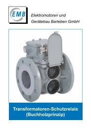
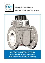
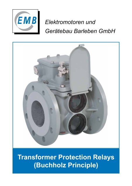
Elektromotoren und<br />
Gerätebau Barleben GmbH<br />
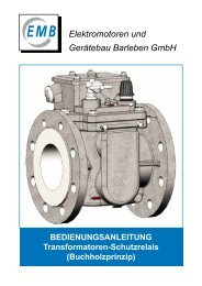
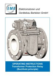
<strong>Transformer</strong> <strong>Protection</strong> <strong>Relays</strong><br />
(<strong>Buchholz</strong> <strong>Principle</strong>)
Elektromotoren und Gerätebau Barleben GmbH<br />
Table of contents<br />
2<br />
Page<br />
Company history 3<br />
1. Preface 4<br />
2. Design features 5<br />
3. Function 7<br />
3.1. Gas accumulation 7<br />
3.2. Insulating liquid loss 8<br />
3.3. Insulating liquid flow 8<br />
4. Tests 9<br />
5. Type list of single-float <strong>Buchholz</strong> relays 10<br />
5.1. Single-float <strong>Buchholz</strong> relays with threaded connection 10<br />
5.2. Single-float <strong>Buchholz</strong> relays with flanged connection 10<br />
6. Switching system design options for single-float <strong>Buchholz</strong> relays 11<br />
7. Type list of double-float <strong>Buchholz</strong> relays 12<br />
7.1. Double-float <strong>Buchholz</strong> relays with threaded connection 12<br />
7.2. Double-float <strong>Buchholz</strong> relays with flanged connection (round) 13<br />
7.3. Double-float <strong>Buchholz</strong> relays with flanged connection (square) 15<br />
7.4. Double-float <strong>Buchholz</strong> relays with geometrical flange dimensions<br />
according to Chinese norm 15<br />
7.5. Double-float <strong>Buchholz</strong> relays with geometrical flange dimensions<br />
according to former French norm 16<br />
7.6. Double-float <strong>Buchholz</strong> relays with geometrical flange dimensions<br />
according to former British standard 17<br />
8. Switching system design options for double-float <strong>Buchholz</strong> relays 18<br />
9. Technical data 22<br />
10. Special designs 23<br />
10.1. Explanations to codes 23 or 24 24<br />
10.2. Explanations to code 32 25<br />
11. Explanations to code 60 - <strong>Buchholz</strong> relay NM series 26<br />
11.1. Design features of <strong>Buchholz</strong> relay NM series 26<br />
11.2. Extra function of <strong>Buchholz</strong> relay NM series 26<br />
11.3. Analogue measuring unit - Analogue measurement of gas volume 27<br />
12. Ordering data/Type code 28<br />
12.1. Single-float <strong>Buchholz</strong> relays 28<br />
12.2. Double-float <strong>Buchholz</strong> relays 28<br />
13. Additional devices for <strong>Buchholz</strong> relays 30<br />
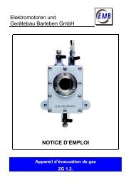
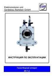
13.1. Gas sampling device ZG 1.2. 30<br />
13.2. Other additional devices for <strong>Buchholz</strong> relays 33<br />
14. Other protection devices 35
Company history<br />
Since its foundation the company has passed through an eventful history with regard to ownership,<br />
affiliation and change of name associated with such development.<br />
1921 Development of <strong>Buchholz</strong> relay by Max <strong>Buchholz</strong><br />
1943 Branch of SIEMENS Magdeburg<br />
1948 VEB Elektromotorenwerk Barleben; VEM<br />
(state-owned firm)<br />
1951 VEB Starkstromanlagenbau Magdeburg<br />
(state-owned firm)<br />
1951 Start of manufacture of <strong>Buchholz</strong> relays in Barleben<br />
1965 Start of manufacture of monitoring relays for tap changers in Barleben<br />
1970 VEB Elektrotechnik und Gerätebau Magdeburg; EGEM<br />
(state-owned firm)<br />
1980 VEB Kombinat Elektromaschinenbau Dresden<br />
VEB Elektromotorenwerk Barleben; VEM; ELMO<br />
(state-owned firm)<br />
1990 VEM Antriebstechnik AG Dresden<br />
Elektromotorenwerk Barleben GmbH; VEM; ELMO<br />
(public limited company)<br />
1993 Elektromotoren und Gerätebau Barleben GmbH; <strong>EMB</strong><br />
(privately owned company)<br />
2005 Start of manufacture of <strong>Buchholz</strong> relays NM series<br />
2009 New premises in Barleben<br />
Figure 1 - <strong>EMB</strong> company building<br />
3
Elektromotoren und Gerätebau Barleben GmbH<br />
1. Preface<br />
The <strong>Buchholz</strong> relay was developed in 1921 by Max <strong>Buchholz</strong>, Oberrat (senior councillor) at Preußische<br />
Elektrizitäts-AG (Prussian electricity supply company) in Kassel. Since that time it has been an<br />
important protection and monitoring device for insulating liquid-filled transformers with conservators<br />
and choke coils. It also allows separate monitoring of oil-filled bushings or cable terminal boxes. It<br />
is mounted in the cooling cycle of the appliance to be protected and responds to faults such as gas<br />
generation, loss of insulating liquid and excessively high flow rates of the latter.<br />
For transformers with hermetical closure by means of a membrane (rubber sack) in the conservator<br />
<strong>Buchholz</strong> relays can be used also as indicating devices (“air cell failure relay”) of this membrane.<br />
The <strong>Buchholz</strong> relay is suitable for open-air as well as indoor installations.<br />
<strong>Buchholz</strong> relays are available in a number of types which comply with norms and standards and<br />
meet special customer requirements. The type of relay to be used depends on the nominal rating<br />
and construction features of the appliance to be protected. Our range of products permits optimum<br />
flexibility.<br />
Elektromotoren und Gerätebau GmbH (<strong>EMB</strong> GmbH) provides more than 60 years experience in<br />
producing <strong>Buchholz</strong> relays and other protection devices for liquid-cooled and liquid-insulated appliances.<br />
It ranks among the most distinguished manufacturers of this type of equipment. <strong>EMB</strong> <strong>Buchholz</strong><br />
relays comply with DIN EN 50216-2 and are known for their easy operation, high reliability and<br />
extremely long life.<br />
Our staff of highly qualified engineers and<br />
experienced skilled workers do their best to<br />
guarantee top quality high-precision products.<br />
The casings are machined on modern CNCcontrolled<br />
machine tools. All products are<br />
subjected to final inspection when all functions<br />
are checked using special test equipment.<br />
Profound experience and expertise are a<br />
sound basis for high product quality.<br />
Extensive references from reputed transformer<br />
manufacturers as well as other users are proof<br />
of the high qualitative level of the products.<br />
The company is certified to<br />
DIN EN ISO 9001/2008.<br />
4<br />
Figure 2 - DIN EN ISO 9001/2008 certificate
2. Design features<br />
Casing<br />
The casing is made of weather-resistant cast<br />
aluminium alloy provided with a paint coat.<br />
It is supplied either with screwed or flanged<br />
connection (1). The different casing designs<br />
available are shown in section 5 for singlefloat<br />
<strong>Buchholz</strong> relays and section 7 for doublefloat<br />
<strong>Buchholz</strong> relays, others are available on<br />
request.<br />
To check the switching system for proper<br />
function, the casing is provided with sightglasses<br />
(2). The sightglasses provided with scales<br />
permit reading of collected gas volume.<br />
The relays can be provided with hinged lids (3)<br />
to protect the sightglasses.<br />
Cover<br />
The upper section of the cover accommodates<br />
the terminal box (1). The test valve (2) and<br />
the test key covered by a cap nut (3) as well<br />
as a plate with instructions for actuating the<br />
test key (4) are arranged in front of the cover.<br />
The terminal box (1) accommodates the earth<br />
terminal (5) and up to eight bushings (6) for<br />
the terminals provided in the base of the cover.<br />
The number of these bushings determines the<br />
design of the switching systems in terms of<br />
type and quantity of the magnet contact tubes.<br />
The terminal box (1) is sealed by an aluminium<br />
cap (7) so that it is safe to touch and protected<br />
against pollution. If the cap is opened the graphic<br />
symbol and the connection diagram (8)<br />
are shown. The cable can be inserted through<br />
the cable gland (9).<br />
1<br />
3<br />
2<br />
1<br />
7<br />
8<br />
9<br />
5<br />
6<br />
1<br />
2<br />
3<br />
4<br />
Figure 3 - Casing with flanged connection<br />
Figure 4 - Casing with threaded connection<br />
Figure 5 - Cover with cap removed<br />
5
Elektromotoren und Gerätebau Barleben GmbH<br />
Switchgear<br />
The switchgear has the following main components:<br />
- Switching system<br />
- Frame<br />
- Mechanical testing unit.<br />
Whereas the single-float <strong>Buchholz</strong> relay has only one switching system, the double-float <strong>Buchholz</strong><br />
relay has an upper and a lower switching system. Permanent magnet and float are rigidly linked<br />
forming an integrated whole that is movably fitted to the frame together with the mechanical testing<br />
unit and the magnet contact tube(s).<br />
Switchgear of a single-float <strong>Buchholz</strong> relay:<br />
- Float<br />
- Permanent magnet(s)<br />
- Magnet contact tube(s)<br />
- Damper<br />
The damper is held in its normal position by a magnet.<br />
Switchgear of a double-float <strong>Buchholz</strong> relay:<br />
- Upper float<br />
- Lower float<br />
- Permanent magnet(s) for upper float<br />
- Permanent magnet(s) for lower float<br />
- Magnet contact tube(s) for upper switching system<br />
- Magnet contact tube(s) for lower switching system<br />
- Damper<br />
The damper is held in its normal position by a magnet<br />
and acts on the lower switching system.<br />
6<br />
Figure 6 - Single-float <strong>Buchholz</strong> relay<br />
Figure 7 - Double-float <strong>Buchholz</strong> relay
3. Function<br />
The <strong>Buchholz</strong> relay is installed in the pipe between the tank of the device to be protected (transformer,<br />
reactor) and the conservator. During normal operation it is filled completely with insulating<br />
liquid.<br />
Due to buoyancy the float of the single-float relay and both floats of the double-float relay are at<br />
their top position.<br />
The upper and lower switching systems form a functional unit in the single-float <strong>Buchholz</strong> relay so<br />
that in the event of a fault the transformer is immediately disconnected from the power system.<br />
In the following the function of a <strong>Buchholz</strong> relay is explained using the example of a double-float<br />
<strong>Buchholz</strong> relay. If a fault occurs inside the transformer, the <strong>Buchholz</strong> relay responds as follows:<br />
3.1. Gas accumulation<br />
Fault: Free gas is available in the insulating liquid.<br />
Response: The gas in the liquid moves upwards, accumulates in the <strong>Buchholz</strong> relay and displaces<br />
the insulating liquid level.<br />
The moving float actuates a switch contact (magnet contact tube). An alarm signal is tripped.<br />
The lower float is not affected as from a certain gas volume the gas flows through a piping to the<br />
conservator.<br />
Oil Öl<br />
Gas<br />
Figure 8 - Gas accumulation<br />
7
Elektromotoren und Gerätebau Barleben GmbH<br />
3.2. Insulating liquid loss<br />
Fault: Insulating liquid loss due to leakage.<br />
Response: As the liquid level falls the top float moves downwards. An alarm is tripped. If the liquid<br />
loss continues, conservator and piping as well as the <strong>Buchholz</strong> relay will be emptied.<br />
As the liquid level falls, the lower float moves downwards. The moving float actuates a switch contact<br />
so that the transformer is disconnected.<br />
3.3. Insulating liquid flow<br />
Fault: A spontaneous incident generates a pressure wave moving in the direction of the conservator.<br />
Response: The liquid flow reaches the damper arranged in the liquid flow. If the flow rate exceeds<br />
the operating value of the damper, the latter moves in flow direction.<br />
Due to this movement a switch contact is actuated so that the transformer is disconnected.<br />
After release of the pressure wave the lower switching system returns to its starting position.<br />
<strong>Buchholz</strong> relays manufactured by <strong>EMB</strong> are equipped with a damper held by a permanent magnet.<br />
8<br />
Luft Air<br />
Oil Öl<br />
Oil Öl<br />
Figure 9 - Insulating liquid loss<br />
Figure 10 - Insulating liquid flow
4. Tests<br />
Each <strong>Buchholz</strong> relay is provided with a works-number that is specified on the test certificate and<br />
the name plate. The tests carried out on the <strong>Buchholz</strong> relay are recorded in the test certificate.<br />
- Dielectric strength test<br />
- Leakage test<br />
- Functional test<br />
- Flow test.<br />
<strong>Buchholz</strong> relays are delivered in cardboard boxes.<br />
For each relay delivered the following documents in the language agreed are proviced:<br />
- Operating instructions<br />
- Test certificate.<br />
The name plate covers the following information:<br />
Type<br />
works-no.<br />
6 digits<br />
switching IP code<br />
element<br />
S = normally-open<br />
Ö = normally-closed<br />
W = changed-over<br />
Figure 11 - Functional and leakage test<br />
date of manufacture<br />
(week/year)<br />
type code<br />
Figure 12 - Flow test<br />
9
Elektromotoren und Gerätebau Barleben GmbH<br />
5. Type list of single-float <strong>Buchholz</strong> relays<br />
5.1. Single-float <strong>Buchholz</strong> relays with threaded connection<br />
h1<br />
10<br />
Type<br />
Internal description<br />
DIN description<br />
01<br />
(AG 25)<br />
(CG 25)<br />
Type of connection<br />
Threaded<br />
connection<br />
G 1½ “<br />
Figure 13 - Dimensional drawing, type 01<br />
Type<br />
Internal description<br />
DIN description<br />
02<br />
(AF 25/6)<br />
(-)<br />
Type of connection<br />
Pipe<br />
diameter<br />
DN (mm)<br />
Flange dimensions<br />
(mm)<br />
Device dimensions<br />
(mm)<br />
d1 d2 d3 d4 d5 f l h1 h2<br />
5.2. Single-float <strong>Buchholz</strong> relays with flanged connection<br />
h1<br />
80<br />
h2<br />
80<br />
h2<br />
250<br />
300<br />
350<br />
03<br />
(AF 25/10)<br />
(-)<br />
25<br />
(AF 25)<br />
(-)<br />
250<br />
300<br />
350<br />
cm 3<br />
l<br />
cm 3<br />
l<br />
Weight<br />
(kg)<br />
Suited for<br />
transformer<br />
ratings of<br />
25 - - - - 16 185 170 62 3,1 ≤1600 KVA<br />
Pipe<br />
diameter<br />
DN (mm)<br />
Figure 14 - Dimensional drawing, type 02, 03, 25<br />
f<br />
f<br />
Flange dimensions<br />
(mm)<br />
Device dimensions<br />
(mm) Weight<br />
(kg)<br />
d1 d2 d3 d4 d5 f l h1 h2<br />
Suited for<br />
transformer<br />
ratings of<br />
Flange<br />
4-hole 25 100 75 60 12 12 185 195 62 3,6 ≤1600 KVA<br />
Flange<br />
4-hole 25 115 85 68 14 16 200 205 62 4,0 ≤1600 KVA<br />
Flange<br />
4-hole 25 100 75 - 12 10 160 195 62 3,3 ≤1600 KVA<br />
d5<br />
170<br />
d1<br />
G11/2"<br />
170<br />
d1<br />
d4<br />
d3<br />
d2<br />
R80<br />
R80
6. Switching system design options for single-float <strong>Buchholz</strong> relays<br />
Magnet contact tubes are used as switching elements. These are normally-open (NO),<br />
normally-closed (NC) and change-over (CO) contacts. The magnet contact tube design can be<br />
derived from the last digit of the type code. For coding, see Ordering data/Type code under<br />
Section 12.1. on page 28.<br />
...1 ...2 ...3 ...4 ...5 ...6<br />
1 NO 1 NC 2 NO 2 NC<br />
13<br />
14<br />
21<br />
22 24 12<br />
11<br />
12<br />
13<br />
14 24<br />
23 11<br />
12 22<br />
1 NO and<br />
1 NC<br />
21 13<br />
11<br />
14 12<br />
...7 ...8 ...9<br />
2 CO 1 NO and 1 CO 1 NC and 1 CO<br />
11<br />
Explanation of symbols:<br />
2<br />
1<br />
4<br />
1 CO<br />
14 24 12 14<br />
23<br />
11<br />
Example: coding „ ... 6 “<br />
Magnet contact tube(s) design<br />
Graphic symbol with terminal marking<br />
Connection diagram in terminal box<br />
The inner side of the cap accommodates a plate with the graphic symbol and the connection<br />
diagram. The schemes show the switching systems in their neutral position. The neutral<br />
position is the operating condition when the <strong>Buchholz</strong> relay is filled with insulating liquid up<br />
the required level and the device to be protected operates without any fault.<br />
21<br />
22<br />
12<br />
11<br />
2<br />
14<br />
1 CO<br />
1<br />
4<br />
11
Elektromotoren und Gerätebau Barleben GmbH<br />
7. Type list of double-float <strong>Buchholz</strong> relays<br />
7.1. Double-float <strong>Buchholz</strong> relays with threaded connection<br />
h1<br />
12<br />
Type<br />
Internal description<br />
DIN description<br />
04<br />
(BG 25)<br />
(DG 25)<br />
21<br />
(BG 25 S)<br />
(-)<br />
Type of connection<br />
Threaded<br />
connection<br />
G 1½ “<br />
Threaded<br />
connection<br />
G 1½ “<br />
Figure 15 - Dimensional drawing, type 04<br />
h1<br />
80<br />
h2<br />
80<br />
h2<br />
250<br />
300<br />
350<br />
cm 3<br />
l<br />
250<br />
300<br />
350<br />
cm 3<br />
Figure 16 - Dimensional drawing, type 21<br />
l<br />
f<br />
f<br />
Pipe<br />
diameter<br />
DN (mm)<br />
Flange dimensions<br />
(mm)<br />
Device dimensions<br />
(mm) Weight<br />
(kg)<br />
d1 d2 d3 d4 d5 f l h1 h2 h 3<br />
Suited for<br />
transformer<br />
ratings of<br />
25 - - - - 16 185 235 90 - 4,2 ≤5000 KVA<br />
25 - - - - 16 185 235 90 - 3,6 ≤5000 KVA<br />
170<br />
d1<br />
G11/2"<br />
150<br />
d1<br />
G11/2"<br />
R143
7.2. Double-float <strong>Buchholz</strong> relays with flanged connection (round)<br />
Type<br />
Internal description<br />
DIN description<br />
05<br />
(BF 25/6)<br />
(-)<br />
06<br />
(BF 25/10)<br />
(DR 25)<br />
23<br />
(BF 25/10 S)<br />
(-)<br />
07<br />
(BF 50/6)<br />
(-)<br />
08<br />
(BF 50/10)<br />
(DR 50)<br />
09<br />
(BF 80/10)<br />
(-)<br />
09-26.<br />
(BF80/10/8)<br />
(DR 80)<br />
24<br />
(BF 80/6)<br />
(-)<br />
Type of connection<br />
Pipe<br />
diameter<br />
DN (mm)<br />
Flange dimensions<br />
(mm)<br />
Device dimensions<br />
(mm) Weight<br />
(kg)<br />
d1 d2 d3 d4 d5 f l h1 h2<br />
Suited for<br />
transformer<br />
ratings of<br />
Flange<br />
4-hole 25 100 75 60 12 12 185 235 90 4,4 ≤5000 KVA<br />
Flange<br />
4-hole 25 115 85 68 14 18 200 235 90 4,8 ≤5000 KVA<br />
Flange<br />
4-hole 25 115 85 68 14 18 200 235 90 4,4 ≤5000 KVA<br />
Flange<br />
4-hole 50 140 110 90 14 12 185 235 80 4,6<br />
Flange<br />
4-hole 50 165 125 102 18 16 195 250 80 5,9<br />
≥5000 KVA<br />
≤10000 KVA<br />
≥5000 KVA<br />
≤10000 KVA<br />
Flange<br />
4-hole 80 200 160 138 18 15 195 265 80 6,2 ≥10000 KVA<br />
Flange<br />
8-hole 80 200 160 138<br />
18<br />
M16<br />
15 195 265 80 6,2 ≥10000 KVA<br />
Flange<br />
4-hole 80 190 150 130 18 15 195 260 80 6,0 ≥10000 KVA<br />
13
Elektromotoren und Gerätebau Barleben GmbH<br />
h1<br />
Figure 17 - Dimensional drawing, type 05, 06, 07, 08, 09, 24<br />
h1<br />
Figure 18 - Dimensional drawing, type 23<br />
h1<br />
80<br />
h2<br />
80<br />
h2<br />
80<br />
h2<br />
Figure 19 - Dimensional drawing, type 09-26.<br />
14<br />
250<br />
300<br />
350<br />
cm 3<br />
l<br />
250<br />
300<br />
350<br />
cm 3<br />
l<br />
250<br />
300<br />
350<br />
cm 3<br />
l<br />
f<br />
f<br />
f<br />
d5<br />
150<br />
d1<br />
d4<br />
d3<br />
d2<br />
170<br />
d1<br />
d4<br />
d3<br />
d2<br />
170<br />
M16<br />
d1<br />
d4<br />
d3<br />
d2<br />
d5<br />
d5<br />
143<br />
R143
h1<br />
7.3. Double-float <strong>Buchholz</strong> relays with flanged connection (square)<br />
Type<br />
Internal description<br />
DIN description<br />
10<br />
(BF 80/Q)<br />
(DQ 80)<br />
Type of connection<br />
Flange<br />
square<br />
4-hole<br />
Figure 20 - Dimensional drawing, type 10<br />
Type<br />
Internal description<br />
DIN description<br />
Type of connection<br />
Pipe<br />
diameter<br />
DN (mm)<br />
Flange dimensions<br />
(mm)<br />
Device dimensions<br />
(mm)<br />
d1 b d3 d4 d5 f l h1 h2<br />
Weight<br />
(kg)<br />
Suited for<br />
transformer<br />
ratings of<br />
80 125 132 - 18 20 200 235 80 5,0 ≥10000 KVA<br />
7.4. Double-float <strong>Buchholz</strong> relays with geometrical flange dimensions<br />
according to Chinese norm<br />
63<br />
(BC 80)<br />
(QJ 80)<br />
Flange<br />
square<br />
4-hole<br />
Figure 21 - Dimensional drawing, type 63<br />
Pipe<br />
diameter<br />
DN (mm)<br />
Flange dimensions<br />
(mm)<br />
Device dimensions<br />
(mm)<br />
d1 b d3 d4 d5 f l h1 h2<br />
Weight<br />
(kg)<br />
Suited for<br />
transformer<br />
ratings of<br />
80 160 160 - 18 15 185 245 80 5,0 ≥10000 KVA<br />
Suitable for connection to Chinese butterfly valves (square flange). Other types on request.<br />
h1<br />
80<br />
h2<br />
80<br />
h2<br />
250<br />
300<br />
350<br />
cm 3<br />
250<br />
300<br />
350<br />
cm 3<br />
l<br />
l<br />
f<br />
f<br />
b<br />
b<br />
d3<br />
d3<br />
170<br />
d1<br />
b<br />
170<br />
d1<br />
b<br />
d5<br />
d5<br />
R143<br />
R143<br />
15
Elektromotoren und Gerätebau Barleben GmbH<br />
7.5. Double-float <strong>Buchholz</strong> relays with geometrical flange dimensions<br />
according to former French norm<br />
h1<br />
80<br />
h2<br />
16<br />
Type<br />
Internal description<br />
DIN description<br />
41<br />
(NF 25)<br />
(-)<br />
42<br />
(NF 50)<br />
(-)<br />
43<br />
(NF 80)<br />
(-)<br />
250<br />
300<br />
350<br />
cm 3<br />
l<br />
Type of connection<br />
Pipe<br />
diameter<br />
DN (mm)<br />
Figure 22 - Dimensional drawing, type 41, 42, 43<br />
Flange dimensions<br />
(mm)<br />
Device dimensions<br />
(mm)<br />
d1 d2 d3 d4 d5 f l h1 h2<br />
Weight<br />
(kg)<br />
Suited for<br />
transformer<br />
ratings of<br />
Flange<br />
4-hole 25 115 85 - 14 8 240 235 90 4,2 ≤5000 KVA<br />
Flange<br />
4-hole 50 165 125 - 18 11 240 250 80 5,1<br />
≥5000 KVA<br />
≤10000 KVA<br />
Flange<br />
4-hole 80 200 160 - 18 11 240 265 80 5,5 ≥10000 KVA<br />
b<br />
150<br />
d1<br />
d3<br />
b<br />
90°<br />
d5
7.6. Double-float <strong>Buchholz</strong> relays with geometrical flange dimensions<br />
according to former British standard<br />
h1<br />
Type<br />
Internal description<br />
DIN description<br />
51<br />
(BS 25)<br />
(-)<br />
52<br />
(BS 50)<br />
(-)<br />
53<br />
(BS 80)<br />
(-)<br />
Type of connection<br />
Flange<br />
square<br />
4-hole<br />
Flange<br />
6-hole<br />
Flange<br />
6-hole<br />
Figure 23 - Dimensional drawing, type 51<br />
h1<br />
80<br />
h2<br />
80<br />
h2<br />
250<br />
300<br />
350<br />
cm 3<br />
l<br />
250<br />
300<br />
350<br />
cm 3<br />
l<br />
Figure 24 - Dimensional drawing, type 52, 53<br />
f<br />
b<br />
Pipe<br />
diameter<br />
DN (mm)<br />
Flange dimensions<br />
(mm)<br />
Device dimensions<br />
(mm)<br />
d1 d2 d3 d4 d5 f l h1 h2<br />
25<br />
50<br />
80<br />
-<br />
-<br />
140<br />
5,51<br />
160<br />
6,30<br />
150<br />
d1<br />
d3<br />
b<br />
170<br />
d1<br />
d3<br />
d2<br />
72<br />
2,83<br />
110<br />
4,33<br />
130<br />
5,12<br />
90°<br />
-<br />
-<br />
-<br />
-<br />
-<br />
-<br />
d5<br />
M10<br />
M10<br />
12<br />
0,47<br />
12<br />
0,47<br />
d5<br />
-<br />
-<br />
12<br />
0,47<br />
13<br />
0,51<br />
R143<br />
127<br />
5<br />
185<br />
7,28<br />
185<br />
7,28<br />
235<br />
9,25<br />
235<br />
9,25<br />
240<br />
9,45<br />
90<br />
3,54<br />
80<br />
3,15<br />
80<br />
3,15<br />
Weight<br />
(kg)<br />
Suited for<br />
transformer<br />
ratings of<br />
3,7 ≤ 5000 KVA<br />
4,8<br />
≥5000 KVA<br />
≤10000 KVA<br />
5,0 ≥10000 KVA<br />
17
Elektromotoren und Gerätebau Barleben GmbH<br />
8. Switching system design options for double-float <strong>Buchholz</strong> relays<br />
Magnet contact tubes are used as switching elements. These are normally-open (NO),<br />
normally-closed (NC) and change-over (CO) contacts. The magnet contact tube design can be<br />
derived from the last two digits of the type code. For coding, see Ordering data/Type code under<br />
Section 12.2. on page 2.<br />
18<br />
...11 BS 25...11 ...12 ...13 ...14 ...15<br />
Alarm Alarm Alarm Alarm Alarm Alarm<br />
1 NO 1 NO 1 NO 1 NO 1 NO 1 NO<br />
13<br />
14<br />
13<br />
14<br />
13<br />
14<br />
Disconnection Disconnection Disconnection Disconnection Disconnection Disconnection<br />
1 NO 1 NO 1 NC 2 NO 2 NC<br />
1 NO and<br />
1 NC<br />
23<br />
24<br />
23<br />
24<br />
11<br />
12<br />
23<br />
13<br />
14<br />
24 34<br />
33 11<br />
13<br />
14<br />
12 22<br />
21 23<br />
...16 ...17 ...19 ...21<br />
Alarm Alarm Alarm Alarm<br />
1 NO 1 NO 1 NO 1 NC<br />
23<br />
24<br />
13<br />
14<br />
Disconnection Disconnection Disconnection Disconnection<br />
12<br />
1 CO 2 CO 3 NO 1 NO<br />
11<br />
14<br />
21<br />
22 24 32<br />
31<br />
34<br />
23<br />
13<br />
14<br />
33<br />
24 34<br />
43<br />
44<br />
11<br />
12<br />
13<br />
14<br />
13<br />
14<br />
11<br />
24 12
...22 ...23 ...24 ...25 ...26 ...27<br />
Alarm Alarm Alarm Alarm Alarm Alarm<br />
1 NC 1 NC 1 NC 1 NC 1 NC 1 NC<br />
11<br />
12<br />
11<br />
12<br />
11<br />
12<br />
Disconnection Disconnection Disconnection Disconnection Disconnection Disconnection<br />
1 NC 2 NO 2 NC<br />
21<br />
22<br />
13<br />
14 24<br />
23 21<br />
22 32<br />
31 13<br />
11<br />
12<br />
1 NO and<br />
1 NC<br />
21<br />
14 22<br />
12<br />
21<br />
22<br />
1 CO 2 CO<br />
11<br />
14<br />
21<br />
22 24 32<br />
...31 ...32 ...33 ...34 ...35 ...36<br />
Alarm Alarm Alarm Alarm Alarm Alarm<br />
1 CO 1 CO 1 CO 1 CO 1 CO 1 CO<br />
21<br />
21<br />
21<br />
22 24 22 24 22 24 22 24 22 24 22 24<br />
Disconnection Disconnection Disconnection Disconnection Disconnection Disconnection<br />
1 NO 1 NC 2 NO 2 NC<br />
13<br />
14<br />
11<br />
12<br />
33<br />
34 44<br />
43 31<br />
21<br />
32 42<br />
21<br />
1 NO and<br />
1 NC<br />
41 13<br />
11<br />
14 12<br />
12<br />
11<br />
12<br />
21<br />
1 CO<br />
11<br />
14<br />
31<br />
34<br />
19
Elektromotoren und Gerätebau Barleben GmbH<br />
20<br />
...41 ...42 ...43 ...44 ...45 ...46<br />
Alarm Alarm Alarm Alarm Alarm Alarm<br />
2 NO 2 NO 2 NO 2 NO 2 NO 2 NO<br />
13<br />
14 24<br />
23 13<br />
14 24<br />
23 13<br />
14 24<br />
23 13<br />
14 24<br />
23 13<br />
14 24<br />
23 23<br />
33<br />
24 34<br />
Disconnection Disconnection Disconnection Disconnection Disconnection Disconnection<br />
1 NO 1 NC 2 NO 2 NC<br />
33<br />
34<br />
14 13 34 33<br />
11<br />
12<br />
33<br />
34 44<br />
43 11<br />
12 22<br />
1 NO and<br />
1 NC<br />
21 33<br />
11<br />
34 12<br />
1 CO<br />
...51 ...52 ...53 ...54 ...55 ...56<br />
Alarm Alarm Alarm Alarm Alarm Alarm<br />
1 NC and<br />
1 NO<br />
11<br />
12 14<br />
13 11<br />
1 NC and<br />
1 NO<br />
12 14<br />
13 11<br />
1 NC and<br />
1 NO<br />
12 14<br />
13 11<br />
1 NC and<br />
1 NO<br />
12 14<br />
13 11<br />
1 NC and<br />
1 NO<br />
12 14<br />
12<br />
13 21<br />
11<br />
14<br />
1 NC and<br />
1 NO<br />
23<br />
22 24<br />
Disconnection Disconnection Disconnection Disconnection Disconnection Disconnection<br />
1 NO 1 NC 2 NO 2 NC<br />
23<br />
24<br />
21<br />
22<br />
23<br />
24 34<br />
33 21<br />
22 32<br />
31 21<br />
1 NC and<br />
1 NO<br />
23<br />
22 24<br />
12<br />
1 CO<br />
11<br />
14
Explanation of symbols: Example: coding „ ...1 2 “<br />
Magnet contact tube(s) design<br />
Upper switching system - Alarm<br />
Lower switching system - Disconnection<br />
13<br />
14<br />
11<br />
12<br />
Alarm<br />
1 NO<br />
Disconnection<br />
1 NC<br />
Graphic symbol with terminal marking<br />
Connection diagram in terminal box<br />
The inner side of the cap accommodates a plate with the graphic symbol and the connection<br />
diagram. The schemes show the switching systems in their neutral position. The neutral<br />
position is the operating condition when the <strong>Buchholz</strong> relay is filled with insulating liquid up<br />
the required level and the device to be protected operates without any fault.<br />
21
Elektromotoren und Gerätebau Barleben GmbH<br />
9. Technical data<br />
The technical data listed in Table 1 are applicable to all <strong>Buchholz</strong> relays manufactured by <strong>EMB</strong>.<br />
<strong>EMB</strong> <strong>Buchholz</strong> relays are in compliance with DIN EN 50216-2. Options available are specified in<br />
tables of Section 10 on page 23. These special designs are coded using the respective code when<br />
ordering <strong>Buchholz</strong> relays.<br />
Parameter Data Notes<br />
Voltage AC 12 V - max. 250 V<br />
DC 12 V - max. 250 V<br />
Current AC 0.01 A - max. 2 A<br />
DC 0.01 A - max. 2 A<br />
Switching capacity AC max. 400 VA<br />
DC max. 250 W<br />
Dielectric strength AC 2500 V<br />
AC 2000 V (normally-open contact)<br />
AC 1000 V (change-over contact)<br />
Temperature range:<br />
- Ambient temperature<br />
- Operating range<br />
* Temperature of the insulating liquid<br />
22<br />
* Viscosity of the insulating liquid<br />
- 40 °C to + 55 °C<br />
- 40 °F to + 131 °F<br />
- 40 °C to + 115 °C<br />
- 40 °F to + 239 °F<br />
1 mm 2 /s to 1100 mm 2 /s<br />
cos φ > 0,5<br />
L/R < 40 ms<br />
between electric circuit and earth<br />
between open contacts<br />
Climatic testing acc. to<br />
DIN EN 60068-2-78: 2002-09<br />
Others on request:<br />
extreme frigid open-air conditions<br />
below - 40 °C or offshore<br />
Resistance against vibration Class 4M6 Classification acc. to<br />
DIN EN 60721-3-4<br />
Resistance to pressure 0.25 MPa<br />
Resistance to vacuum < 2.5 kPa<br />
Insensitivity to magnetic fields 25 mT Static magnetic field of any<br />
direction and polarity<br />
Switching system:<br />
- Number of switching contacts<br />
- Switching element<br />
- Damper<br />
Response time of damper<br />
Response of switching system in<br />
case of:<br />
- Gas accumulation<br />
- Insulating liquid flow<br />
Pipe diameter DN of<br />
25 mm, 50 mm or 80 mm<br />
1<br />
Magnet contact tube<br />
Held by magnets<br />
< 0.1 s<br />
200 cm 3 to 300 cm 3<br />
min. 0.65 to max. 3.00 m/s<br />
+/- 15%<br />
More on request<br />
For possible data see Ordering<br />
data/Type code under Section 12<br />
on pages 28 and 29.<br />
Cable gland M20x1.5; M25x1.5 Others on request<br />
Nominal installation position 0° to 5° Ascending towards conservator<br />
IP code IP 54; IP 56; IP 66 Others on request<br />
Casing colour Two-component texture paint On polyurethane basis
10. Special designs<br />
<strong>Buchholz</strong> relay NM series<br />
Explanation Code<br />
NM series - <strong>Buchholz</strong> relay with analogue measurement of the gas volume<br />
(only double-float <strong>Buchholz</strong> relays) 60<br />
Casing colour<br />
Casing colour RAL 7001 (silver-grey) 41<br />
Casing colour RAL 7012 (basalt-grey) 42<br />
Casing colour RAL 7022 (umber-grey) 43<br />
Casing colour RAL 7033 (cement-grey) 44<br />
Casing colour RAL 7038 (agate-grey) 45<br />
Casing colour RAL 7035 (light-grey) 46<br />
Casing colour RAL 7016 (anthracite-grey) 47<br />
Casing colour RAL 9002 (grey-white) 48<br />
Casing colour RAL 7032 (siliceous-grey) 49<br />
Climate-proof version<br />
Climate-proof version (extreme frigid open-air conditions below - 40 °C) 34<br />
Climate-proof version (offshore) 36<br />
IP code<br />
IP code IP 56 38<br />
IP code IP 66 39<br />
Insulating liquid<br />
Insulating liquid silicone oil 20<br />
Insulating liquid based on esther 21<br />
Casing<br />
With oil drain plug (only double-float <strong>Buchholz</strong> relays) 28<br />
With premounted Harting-Connector<br />
(The option is indicated by a letter after the code.) 59<br />
Switching system (for design options see page 11 or pages 18-20)<br />
Upper switching system equipped with two magnet contact tubes 35<br />
Lower switching system equipped with two magnet contact tubes 25<br />
Upper and lower switching system each equipped with two magnet contact tubes 33<br />
Lower switching system equipped with three magnet contact tubes<br />
Testing of the switching systems by means of compressed-air and test key<br />
99<br />
(only double-float <strong>Buchholz</strong> relays) 32<br />
Damper held in response position (only double-float <strong>Buchholz</strong> relays) 23<br />
Special design approved by RWE, Germany (only double-float <strong>Buchholz</strong> relays) 24<br />
Special request<br />
Special request (on special agreement with customer) 29<br />
23
Elektromotoren und Gerätebau Barleben GmbH<br />
For engineering reasons the following special designs cannot be combined in the same device:<br />
10.1. Explanations to codes 23 or 24<br />
<strong>Buchholz</strong> relays with the feature „damper held in response position“ are designed such that the<br />
damper after it was operated due to an unacceptable high flow rate of the insulating liquid is<br />
locked in its position and, hence is kept in this position even after the flow rate has been reduced.<br />
This means that the signal generated is maintained.<br />
The damper has to be unlocked manually by turning the test key anticlockwise. When unlocking<br />
the damper, also check the insulating liquid level in the <strong>Buchholz</strong> relay. Bleed the <strong>Buchholz</strong> relay,<br />
if required.<br />
24<br />
Code combination Code combination Code combination<br />
60 - 32 32 - 23, 24 33 - 23, 24<br />
60 - 33 32 - 25 33 - 99<br />
60 - 34 32 - 33<br />
60 - 35 32 - 35 35 - 23, 24<br />
60 - 36<br />
60 - 59<br />
32 - 99 35 - 99<br />
60 - 99 99 - 23, 24
10.2. Explanations to code 32<br />
For <strong>Buchholz</strong> relays provided additionally with an air nipple (code 32), the mechanical function of<br />
the two switching systems can be tested by means of test key (1), and the upper switching system<br />
(alarm) can be tested by pumping in air via the test valve (2) using a suitable test pump. Additionally,<br />
the switching systems can be tested pneumatically. To this end, air is supplied via an air<br />
supply nipple (3) provided with a check valve. Perform the test while the <strong>Buchholz</strong> relay is filled with<br />
insulating liquid up to the required level.<br />
Pneumatic test of the upper switching system (alarm) using compressed air:<br />
Air is introduced slowly into the <strong>Buchholz</strong> relay through the air supply nipple and the pipe air until<br />
the alarm contact is made when the upper float is lowered.<br />
Pneumatic test of the lower switching system (disconnection) using compressed air:<br />
Through the air supply nipple and the pipe air is applied suddenly to the damper. When the damper<br />
responds the disconnection contact is made.<br />
After any test using air, bleed the <strong>Buchholz</strong> relay through the test valve.<br />
The functional test using compressed air results from British Standard B.E.B.S. T2 of 1966.<br />
Figure 25 - Cover with additional air supply nipple<br />
2 3 1<br />
25
Elektromotoren und Gerätebau Barleben GmbH<br />
11. Explanations to code 60 - <strong>Buchholz</strong> relay NM series<br />
11.1. Design features of <strong>Buchholz</strong> relay NM series<br />
The principal construction of the <strong>Buchholz</strong> relay with floats and damper as well as their electromechanical<br />
functions have been maintained.<br />
The <strong>Buchholz</strong> relay of series NM is equipped additionally with a capacitive sensor. The sensor is<br />
installed in the cover of the <strong>Buchholz</strong> relay. The cap of the terminal box accommodates the electronic<br />
amplifier of the measuring unit. Sensor and amplifier are connected by a shielded cable<br />
in three-wire technology of 15 m length with a cable connector. This cable is used for the supply<br />
voltage and the output signal.<br />
Figure 26 shows the arrangement of the measuring unit using the example of a <strong>Buchholz</strong> relay BF<br />
80/10/8. Apart from the dust hood and the cap of the terminal box which are higher by approx. 30<br />
mm, the installation dimensions of the relay have not been changed. Hence, relays with analogue<br />
measuring units can be installed in existing systems.<br />
291<br />
Figure 26 - Dimensional drawing <strong>Buchholz</strong> relay NM series type 09-26. (BF 80/10/8)<br />
11.2. Extra function of <strong>Buchholz</strong> relay NM series<br />
The standard <strong>Buchholz</strong> relay detects undissolved gases in the insulating liquid and indicates their<br />
presence when a specified threshold is exceeded, meaning that up to a certain gas volume, no<br />
signal is generated. Neither is it possible to gather information about the length of time it takes for<br />
gas to accumulate.<br />
The process of the generation of unsolved gases in the insulating liquid over time is a very important<br />
criterion for the evaluation of the fault as the quantity and composition of the fault gases<br />
depend on the kind and quantity of the energy of the underlying fault. Spontaneous and energyrich<br />
faults cause large gas quantities within a short period of time, whilst small volumes of gas are<br />
generated in the case of minor and insidious faults.<br />
The <strong>Buchholz</strong> relay of NM series allows continuous and analogue gas volume measurement so<br />
that gases which have accumulated in the relay are detected at an early stage, information about<br />
the generation of the gases obtained and the conditions provided for the analysis of the fault at an<br />
early stage.<br />
26<br />
109<br />
80<br />
195<br />
15<br />
138<br />
200<br />
M16<br />
170<br />
80<br />
160<br />
18<br />
R143
The extra function of the NM series relays is ensured by a capacitive sensor and the appropriate<br />
electronic components. Supply voltage of this assembly is DC 24 V. This voltage must be made<br />
available by the user. The output signal of the measuring unit is a standard current signal of<br />
DC 4 to 20 mA. It depends on the user how and in what form this signal is processed.<br />
DC 4 - 20 mA<br />
Monitoringsystem<br />
Extra function<br />
of the <strong>Buchholz</strong><br />
relay NM series<br />
DC 24 V<br />
Conversion and<br />
processing<br />
Figure 27 - Extra function of <strong>Buchholz</strong> relay NM series<br />
11.3. Analogue measuring unit - Analogue measurement of gas volume<br />
The measured value is based on capacitance variation of the sensor caused by variation of the<br />
insulating liquid level in the <strong>Buchholz</strong> relay.<br />
Analogue measurement of the gas volume is possible between 50 cm 3 and 300 cm 3 . Lower gas<br />
volumes cannot be measured reliably because of high inaccuracies. Measurements beyond this<br />
range are not necessary as in this case the upper switching system will respond. Besides, the<br />
construction of the <strong>Buchholz</strong> relay (larger gas volumes escape towards the conservator) does not<br />
allow such measurements. The operating point of the upper switching system (upper float) is a gas<br />
volume of 200-300 cm 3 .<br />
Fault: Free gas is available in the insulating liquid.<br />
Standard function<br />
of the <strong>Buchholz</strong> relay<br />
DC 12 V - max. 250 V<br />
DC 0,01 A - max. 2 A<br />
Disconnection Alarm<br />
Response: The gas in the liquid moves upwards, accumulates in the <strong>Buchholz</strong> relay and displaces<br />
the insulating liquid. This decreases the level of insulating liquid. Liquid level changes lead to variation<br />
of the capacity of the sensor. This change is converted into an analogue current signal.<br />
It should be noted that for design reasons the current value of the sensor remains relatively constant<br />
up to a gas volume of approx. 50 cm 3 . The function equation will provide the actual volume<br />
only when the current signal becomes smaller and, hence the calculated volume noticeably larger.<br />
27
Elektromotoren und Gerätebau Barleben GmbH<br />
12. Ordering data/Type code<br />
For placing orders, please, use the following key:<br />
12.1. Single-float <strong>Buchholz</strong> relays<br />
0 = not occupied<br />
Type<br />
(see Section 5)<br />
Special design<br />
(see Section 10)<br />
Damper setting (m/s)<br />
01 = 0,65 +/- 15%<br />
02 = 1,00 +/- 15%<br />
03 = 1,50 +/- 15%<br />
Contact setting of<br />
switching system<br />
1 = one NO contact<br />
2 = one NC contact<br />
3 = two NO contacts<br />
4 = two NC contacts<br />
5 = one NO and one NC contact<br />
6 = one CO contact<br />
7 = two CO contacts<br />
8 = one NO and one CO contact<br />
9 = one NC and one CO contact<br />
12.2. Double-float <strong>Buchholz</strong> relays<br />
Ordering example for double-float <strong>Buchholz</strong> relays:<br />
XX XX. XX. X 0 X<br />
For switching system design options for singlefloat<br />
<strong>Buchholz</strong> relays, see Section 6 on page 11.<br />
You need a <strong>Buchholz</strong> relay of type BF 80/Q. The damper should respond at a flow rate of 1.50 m/s.<br />
The upper switching system should be equipped with one switching element (magnet contact tube)<br />
and the lower with two switching elements (magnet contact tubes). The upper switching element<br />
should be designed as one normally open contact, and the lower as two normally open contacts.<br />
The device should be delivered in colour RAL 7033 and should have one oil drain plug.<br />
Based on the data on page 29 the relay ordered has the following<br />
Type code: 10-25.28.44.-0313<br />
Legend:<br />
NO= normally-open contact<br />
NC = normally-closed contact<br />
CO = change-over contact<br />
Explanation: 10 = Double-float <strong>Buchholz</strong> relay type 10 (BF 80/Q)<br />
25 = Lower switching system equipped with 2 magnet contact tubes<br />
28 = With oil drain plug<br />
44 = Casing colour RAL 7033 (cement-grey)<br />
03 = Damper setting: 1.50 m/s +/- 15 %<br />
1 = Contact setting of upper switching system: 1 NO<br />
3 = Contact setting of lower switching system: 2 NO<br />
28
Double-float <strong>Buchholz</strong> relays<br />
Type<br />
(see Section 7)<br />
Special design<br />
(see Section 10)<br />
Damper setting (m/s)<br />
01 = 0,65 +/- 15% 11 = 1,20 +/- 15%<br />
02 = 1,00 +/- 15% 12 = 1,25 +/- 15%<br />
03 = 1,50 +/- 15% 13 = 1,30 +/- 15%<br />
04 = 2,00 +/- 15% 14 = 1,40 +/- 15%<br />
05 = 2,50 +/- 15% 15 = 1,80 +/- 15%<br />
06 = 3,00 +/- 15%<br />
Contact setting of<br />
upper switching system<br />
(alarm)<br />
1 = one NO contact<br />
2 = one NC contact<br />
3 = one CO contact<br />
4 = two NO contacts<br />
5 = one NC and one NO contact<br />
Contact setting of<br />
lower switching system<br />
(disconnection)<br />
1 = one NO contact<br />
2 = one NC contact<br />
3 = two NO contacts<br />
4 = two NC contacts<br />
5 = one NO and one NC contact<br />
6 = one CO contact<br />
7 = two CO contacts<br />
9 = three NO contacts<br />
XX XX. XX. XX X X<br />
Legend:<br />
NO= normally-open contact<br />
NC = normally-closed contact<br />
CO = change-over contact<br />
For switching system design options for double-float<br />
<strong>Buchholz</strong> relays, see Section 8 on pages 18-20.<br />
29
Elektromotoren und Gerätebau Barleben GmbH<br />
13. Additional devices for <strong>Buchholz</strong> relays<br />
13.1. Gas sampling device ZG 1.2.<br />
The gas sampling device is mounted on the transformer and connected to the <strong>Buchholz</strong> relay<br />
by means of a pipe. It allows sampling of the relay gas at normal operating level.<br />
The length of the pipe can be selected by the customer (please, see page 31).<br />
The device can be delivered with a lockable box.<br />
Figure 28 - Gas sampling device ZG 1.2. Figure 29 - Gas sampling device ZG 1.2.<br />
in lockable box<br />
Figure 30 - Pipe of gas sampling device ZG 1.2. Figure 31 - Sightglass cover for<br />
gas sampling device ZG 1.2.<br />
30
Technical data<br />
Parameter Data Notes<br />
Gas outlet opening G 1/8“ Others on request<br />
Oil outlet opening G 1/8“ Others on request<br />
Temperature range:<br />
- Ambient temperature<br />
- Operating range<br />
* Temperature of the insulating liquid<br />
- 40 °C to + 55 °C<br />
- 40 °F to + 131 °F<br />
- 40 °C to + 115 °C<br />
- 40 °F to + 239 °F<br />
* Viscosity of the insulating liquid 1 mm2 /s to 1100 mm2 Others on request:<br />
extreme frigid open-air conditions<br />
below - 40 °C or offshore<br />
/s<br />
Weight without piping 2,2 kg<br />
Dimensions of pipe Ø 6x1 copper<br />
Length of pipe < 20 m As requested by customer<br />
Casing colour Two-component texture paint On polyurethane basis<br />
Special designs:<br />
Colour<br />
Explanation Code<br />
Casing colour RAL 7001 (silver-grey) 41<br />
Casing colour RAL 7012 (basalt-grey) 42<br />
Casing colour RAL 7022 (umber-grey) 43<br />
Casing colour RAL 7033 (cement-grey) 44<br />
Casing colour RAL 7038 (agate-grey) 45<br />
Casing colour RAL 7035 (light-grey) 46<br />
Casing colour RAL 7016 (anthracite-grey) 47<br />
Casing colour RAL 9002 (grey-white) 48<br />
Casing colour RAL 7032 (siliceous-grey) 49<br />
Climate-proof version<br />
Climate-proof version (extreme frigid open-air conditions below - 40 °C) 34<br />
Climate-proof version (offshore) 36<br />
Insulating liquid<br />
Insulating liquid silicone oil 20<br />
Insulating liquid based on esther 21<br />
Special request<br />
Special request (on special agreement with customer) 29<br />
31
Elektromotoren und Gerätebau Barleben GmbH<br />
210<br />
15<br />
Figure 32 - Dimensional drawing, type ZG 1.2.<br />
32<br />
90 XX. XX. X XX,XXm<br />
Type for<br />
ZG 1.2.<br />
125<br />
Ordering data/Type code of gas sampling device ZG 1.2.<br />
Special designs<br />
(see page 31)<br />
0 = without box<br />
1 = with box<br />
Ordering example of gas sampling device ZG 1.2.:<br />
9<br />
30<br />
93<br />
Length of pipe<br />
in meters<br />
Type code: 90-34.44.-0-10,50m<br />
Explanation: 90 = Gas sampling deviceZG 1.2.<br />
34 = Climate-proof version (extreme frigid open-air conditions below - 40 °C)<br />
44 = Casing colour RAL 7033 (cement-grey)<br />
0 = Without box<br />
10,50m = Length of pipe 10,50 m<br />
10
13.2. Other additional devices for <strong>Buchholz</strong> relays<br />
Gas testing device ZG 3.1.<br />
The gas testing device is used to test the gas accumulated in the <strong>Buchholz</strong><br />
relay. It can be installed either directly on the test valve of the <strong>Buchholz</strong> relay<br />
or on the gas outlet tap of the gas sampling device. The <strong>Buchholz</strong> gas flows<br />
through two different chemical solutions and its colour reactions indicate the<br />
nature of the fault.<br />
Use of the gas testing device is no substitute for a gas chromatographic<br />
analysis.<br />
Reflux lock ZG 4.1.<br />
The device prevents insulating liquid from flowing into the gas testing device.<br />
The device is installed between the <strong>Buchholz</strong> relay or gas sampling device<br />
and the gas testing device.<br />
Test pump ZG 5.1. and ZG 5.2.<br />
The test pump checks the functioning of the upper switching system (alarm)<br />
of the <strong>Buchholz</strong> relay by pumping in air. The test can be performed directly<br />
on the <strong>Buchholz</strong> relay. For that purpose, the test pump is connected to<br />
the test valve of the <strong>Buchholz</strong> relay. When the test is performed via the gas<br />
sampling device, the test pump is connected to the gas outlet tap of the gas<br />
sampling device.<br />
- ZG 5.1. manually operated<br />
- ZG 5.2. pedal-operated<br />
Oil sampling device ZG 6.1.<br />
The oil sampling device is connected to the <strong>Buchholz</strong> relay via a pipe and<br />
is used to take oil samples from the <strong>Buchholz</strong> relay (suitable for use with<br />
<strong>Buchholz</strong> relays with an oil drain plug). The pipe is supplied to the customer’s<br />
specifications.<br />
33
Elektromotoren und Gerätebau Barleben GmbH<br />
34<br />
<strong>Buchholz</strong> gas sampler BGS<br />
The <strong>Buchholz</strong> gas sampler provides a safe method of taking and transporting<br />
gas samples from the <strong>Buchholz</strong> relay or the gas sampling device. Its capacity<br />
is 100 ml.<br />
<strong>Buchholz</strong> gas tester BGT<br />
The <strong>Buchholz</strong> gas tester is used to measure the hydrogen concentration of<br />
the <strong>Buchholz</strong> gases. The measurement can be performed directly where the<br />
sample is taken.<br />
For other gas testing equipment, please, contact us.
14. Other protection devices<br />
Monitoring relay for tap changers ÜRF 25, ÜRF 25/10, ÜRF 25/10-26<br />
The monitoring relay for tap changers, also known as the protection relay for<br />
tap changers or oil flow relay, is a monitoring device for insulating liquid-filled<br />
tap changers with conservator. It protects the tap changer and the transformer<br />
from damage. The monitoring relay responds to excessive oil flow in the<br />
direction of the conservator and generates a signal disconnecting the tap<br />
changer and the transformer immediately from voltage supply.<br />
Pipe diameter DN: 25 mm (1“)<br />
Type of connection: threaded or flanged<br />
Oil flow indicator SG 25, SF 25, SF 25/10<br />
The oil flow indicator is a protective relay monitoring the circulating oil lubrication<br />
or circulating oil cooling of machines and equipment. It indicates faults<br />
in circulating oil systems or shuts down the machine or equipment, thus preventing<br />
damage. The flow indicator operates at a very low service pressure,<br />
so it can be installed in an oil return pipe where the oil flow is ensured by the<br />
sloping pipe.<br />
Pipe diameter DN: 25 mm (1“)<br />
Type of connection: threaded or flanged<br />
For further information, please ask for special reference material.<br />
35
<strong>EMB</strong> GmbH<br />
Otto-von-Guericke-Allee 12<br />
D-39179 Barleben | Germany<br />
Phone: +49 39203 790<br />
Fax: +49 39203 5330<br />
Email: info@emb-online.de<br />
Website: www.emb-online.de<br />
www.buchholzrelay.com<br />
Due to technical improvement of our products, the information contained in this catalogue is subject to change without notice.<br />
We would like to apologize for any printing errors which have not been found despite of intensive proof-reading.<br />
Edition: Catalogue <strong>Buchholz</strong> relays KA 01/01/12/02 English<br />
Elektromotoren und<br />
Gerätebau Barleben GmbH<br />
Köln<br />
Frankfurt<br />
Hamburg<br />
Hannover<br />
Barleben<br />
Magdeburg<br />
München<br />
Leipzig<br />
Berlin