Leica DVM - 3D Visualisation
Leica DVM - 3D Visualisation
Leica DVM - 3D Visualisation

Create successful ePaper yourself
Turn your PDF publications into a flip-book with our unique Google optimized e-Paper software.
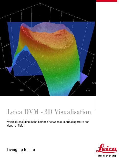
<strong>Leica</strong> <strong>DVM</strong> - <strong>3D</strong> <strong>Visualisation</strong><br />
Vertical resolution in the balance between numerical aperture and<br />
depth of field<br />
Living up to Life
Vertical resolution in the balance between<br />
numerical aperture and depth of field<br />
Digital microscopy offers clear advantages for a wide variety of industrial quality inspections, particularly surface<br />
analyses. Fracture analyses, analyses of inclined or vertical surfaces or onsite inspections of large parts such as turbine<br />
rotors are just a few examples in which the strengths of digital microscopes make the biggest difference. But what are<br />
the key criteria for successful use of digital microscopes and which parameters affect the three-dimensional imaging to<br />
be expected for these specimens?<br />
One of the main features of a digital microscope is the speed and ease with which it enables surface models to be created<br />
of macroscopic and microscopic structures. In a qualitative evaluation, these provide better understanding and documentation<br />
of the specimen. In addition, quantification of the surface provides valuable information about the composition of<br />
the surface and its wear. Which specimens are suitable for use with a <strong>Leica</strong> digital microscope, and what are the limitations<br />
of the method used?<br />
The three-dimensional imaging of the <strong>Leica</strong> <strong>DVM</strong> series is based on the principle of focus variation. The limited depth of<br />
field of the optics is utilized to determine depth information for the specimen. Vertical movement of the specimen relative<br />
to the objective determines the focus information along with the distance to the optics. For each vertical position, the area<br />
of the image that is in sharp focus is separated from the blurry area, and both are processed by the software to create a<br />
surface model. One of the advantages of this method is that in addition to the height information, the texture of the specimen<br />
is also documented.<br />
Which influencing factors are determinative for successful creation of a 3-D surface model and how do these<br />
variables influence lateral and vertical resolution?<br />
2
Depth of field<br />
The author of the first publication on<br />
the subject of visually perceived depth<br />
of field was Max Berek, who published<br />
the results of his extensive experiments<br />
as early as 1927. Berek's formula<br />
gives practical values for visual depth<br />
of field and is therefore still used today.<br />
In simplified form, it is as follows:<br />
T VIS : Visually perceived depth of field<br />
n: : Refractive index of the medium<br />
in which the specimen is situated. If<br />
the specimen is moved, the refractive<br />
index of the medium that forms the<br />
changing working distance is entered<br />
in the equation.<br />
l: Wavelength of the light used; for<br />
white light, lambda = 0.55 μm<br />
NA: Specimen-side numerical aperture<br />
M TOT VIS : Visual total magnification of the<br />
microscope<br />
If in the equation above, we replace<br />
the visual total magnification with the<br />
relationship of the useful magnification<br />
(M TOT VIS = 500 bis 1000·NA), it becomes<br />
clear that in a first approximation, the<br />
depth of field is inversely proportional<br />
to the square of the numerical aperture.<br />
Optics and Surfaces<br />
1. Optics – in the balance between numerical aperture and depth of field<br />
In microscopy, depth of field is in many cases an empirically understood<br />
metric. In practice, the correlations between the numerical aperture, resolution<br />
and magnification determine this parameter. With their adjustment<br />
options, today's microscopes create a balance between depth of field and<br />
resolution that is optimal for the visual impression – two parameters that in<br />
theory are inversely correlated. In DIN/ISO standards, the specimen-side<br />
depth of field is defined as the "axial depth of the space on both sides of the<br />
specimen plane in which the specimen can be moved without detectable<br />
loss of sharpness in the image focus, while the positions of the image plane<br />
and objective are maintained."<br />
T VIS = n·[l/(2·NA 2 ) + 340 μm/(NA·M TOT VIS )]<br />
4<br />
However, the standard does not give any clues on how to measure the<br />
detection threshold of the deterioration of focus. Particularly at low magnifications,<br />
the depth of field can be significantly increased by stopping<br />
down, i.e. reducing the numerical aperture. This is usually done using<br />
the aperture diaphragm or a diaphragm that is on a conjugated plane to<br />
the aperture diaphragm. However, the smaller the numerical aperture,<br />
the lower the lateral resolution. Thus it is a matter of finding the optimum<br />
balance of resolution and depth of field depending on the structure of the<br />
specimen.<br />
2. Texture of the specimen<br />
The texture of the specimen surface, also known as its composition,<br />
encompasses all of its features and characteristics. These include color<br />
and brightness characteristics of the surface. As described above, the<br />
principle of focus variation is based on the methodical approach of a lack<br />
of specimen sharpness. The better the specimen can be divided into sharp<br />
and out-of-focus areas, the better the results of the surface model will be.<br />
This method is particularly well suited to textures that have a good contrast.<br />
As in many application areas of microscopy, the illumination is given<br />
an especially important status, as it frequently determines success or failure.<br />
Selecting a suitable illumination makes it possible to document even<br />
a specimen with little texture. For example, you can select an oblique incident<br />
illumination that makes even hidden structures visible.
Mechanics and Illumination<br />
3. Mechanical resolution in the vertical direction<br />
The third influencing factor in this equation is the mechanical<br />
resolution in the vertical direction. This term means<br />
the smallest possible steps in the z-direction of the focusing<br />
drive, which is usually motorized. To make full use of the<br />
performance capacity of the optics, the smallest possible<br />
step must be smaller than the currently used depth of field,<br />
as otherwise image data are lost. A motorized focus drive<br />
with a resolution of 10μm, for example, is suitable at a depth<br />
of field of 15μm.<br />
Which lateral and vertical resolutions are possible with a<br />
<strong>Leica</strong> <strong>DVM</strong> system? As described above, these parameters<br />
depend on various influencing factors, such as the surface<br />
structure or illuminator, and thus must be determined<br />
depending on the application. Interpolation attains a vertical<br />
resolution of one-half of the applied depth of field. The<br />
lateral resolution is determined by the numerical aperture<br />
of the magnification used.<br />
6<br />
Illumination<br />
Selecting the suitable illumination is critical to<br />
the success of the examination. The modular<br />
structure of the <strong>Leica</strong> <strong>DVM</strong> product concept<br />
enables you to combine the selected optics<br />
with the optimal illumination for the application.<br />
The following methods are available for<br />
selection:<br />
1) Variable oblique incident illumination: This<br />
method changes the illumination direction<br />
from vertical to lateral. This approach is particularly<br />
suitable for visualizing scratches or<br />
small recesses.<br />
2) Diffuser: For shiny surfaces, the dynamic<br />
range of the camera is insufficient in many<br />
cases and many areas of the specimen are<br />
overexposed. A diffuser provides reliable<br />
reduction of the overexposed area.<br />
3) Coaxial illuminator: A coaxial illuminator<br />
is used for very shiny or reflective surfaces,<br />
such as wafers or metal sections.<br />
4) Polarized light: is used to supress the reflections<br />
or for documentation of plastic materials.<br />
5) Coaxial illuminator with directed light: In<br />
the applications described above, the directed<br />
light creates a three-dimensional impression<br />
of the specimen. This is helpful in many cases<br />
for determining the surface with greater accuracy.
u<br />
Coin with incident illumination Coin with oblique incident illumination<br />
v<br />
Soder joint without diffusor Soder joint with diffusor<br />
w<br />
Semiconductor with coaxial illumination Semiconductor with coaxial illumination<br />
x<br />
Plastic with polarised light Watch with polarised light<br />
y<br />
Semiconductor with coaxial illumination Semiconductor with directed coaxial illumination
Maximum vertical resolution of <strong>Leica</strong> <strong>DVM</strong> systems<br />
Zoom Depth of field at Vmax Vertical resolution<br />
<strong>Leica</strong> VZ75 C @160x 250 μm 125 μm<br />
<strong>Leica</strong> VZ80 C / <strong>Leica</strong> VZ80 RC @ 400x 80 μm 40 μm<br />
<strong>Leica</strong> VZ100 @ 350x (10450392) 420 μm 210 μm<br />
<strong>Leica</strong> VZ100 @ 700x (10450393) 110 μm 55 μm<br />
<strong>Leica</strong> VZ100 @ 1400x (10450394) 4 μm 2 μm<br />
<strong>Leica</strong> VZ100 @ 1400x (10450395) 3 μm 1.5 μm<br />
<strong>Leica</strong> VZ100 @ 3500x (10450411) 1 μm 500 nm<br />
<strong>Leica</strong> VZ100 @ 7000x (10450412) 700 nm 350 nm
Example from a real-world application<br />
To illustrate this, let us provide an example from a real-word<br />
application. The fracture plane of steel in a tensile test is<br />
to be determined for quality inspection. The desired results<br />
are a qualitative representation as well as a quantitative<br />
statement about the surface. The desired vertical resolution<br />
is to be at least 120μm.<br />
Here are the key optical and mechanical data of the equipment<br />
used:<br />
• Optics used: <strong>Leica</strong> VZ80 RC, 8:1 zoom with magnification<br />
range 50 – 400x, at a maximum magnification of 400x<br />
• Depth of field at maximum magnification of 400x is 80μm<br />
• Resolution of the motorized focusing drive is 500 nm<br />
In the example provided here, a theoretical vertical resolution<br />
of 40μm (depth of field / 2) is attained. The texture of<br />
the specimen to be examined has a high contrast range and<br />
can be distinguished easily by the software into sharp and<br />
out-of-focus areas. Therefore, the <strong>Leica</strong> <strong>DVM</strong> equipment<br />
configuration selected is outstandingly well suited for this<br />
application area and the required vertical resolution can be<br />
attained.<br />
Resolution and application limits of <strong>Leica</strong> <strong>DVM</strong> systems<br />
Based on the requirements of the specimen, it is easy to<br />
determine the suitable zoom optics. Usually, the criteria for<br />
the decision are the field of view and the lateral and vertical<br />
resolution. Generally speaking, the applications of <strong>Leica</strong><br />
digital microscopy are in the microscopic and macroscopic<br />
area. For example, you want to examine an object field of<br />
0.2 mm with a vertical resolution of 10 μm. From the technical<br />
data provided, you can tell that the <strong>Leica</strong> VZ100 with<br />
a 140x objective is suitable for this application. Additional<br />
help is provided by the <strong>Leica</strong> SmartTouch control unit based<br />
on a touch panel, which shows the specific depth of field<br />
being used on the display.<br />
A challenge is presented by specimens that consist of<br />
transparent plastic, for example, and are to be captured in<br />
the microscopic range, i.e. with a digital magnification of<br />
greater than 1400x. The material provides only a little texture<br />
and the results will be unsatisfactory, even though the<br />
<strong>Leica</strong> <strong>DVM</strong> system is optically and mechanically suited to<br />
the task.<br />
What alternatives do you have? For specimens with little<br />
texture, you can switch to another imaging method, such<br />
as confocal microscopy or interferometry. <strong>Leica</strong> DCM <strong>3D</strong>,<br />
for example, combines both technologies in one instrument<br />
and is exceptionally well suited to specimens with little texture.<br />
The table on the left provides an overview of the performance<br />
capabilities and application areas of the <strong>Leica</strong> <strong>DVM</strong><br />
systems.
“With the user, for the user”<br />
<strong>Leica</strong> Microsystems<br />
<strong>Leica</strong> Microsystems operates globally in four divi sions,<br />
where we rank with the market leaders.<br />
• Life Science Division<br />
The <strong>Leica</strong> Microsystems Life Science Division supports the<br />
imaging needs of the scientific community with advanced<br />
innovation and technical expertise for the visualization,<br />
measurement, and analysis of microstructures. Our strong<br />
focus on understanding scientific applications puts <strong>Leica</strong><br />
Microsystems’ customers at the leading edge of science.<br />
• Industry Division<br />
The <strong>Leica</strong> Microsystems Industry Division’s focus is to<br />
support customers’ pursuit of the highest quality end result.<br />
<strong>Leica</strong> Microsystems provide the best and most innovative<br />
imaging systems to see, measure, and analyze the microstructures<br />
in routine and research industrial applications,<br />
materials science, quality control, forensic science investigation,<br />
and educational applications.<br />
• Biosystems Division<br />
The <strong>Leica</strong> Microsystems Biosystems Division brings histopathology<br />
labs and researchers the highest-quality,<br />
most comprehensive product range. From patient to pathologist,<br />
the range includes the ideal product for each<br />
histology step and high-productivity workflow solutions<br />
for the entire lab. With complete histology systems featuring<br />
innovative automation and Novocastra reagents,<br />
<strong>Leica</strong> Microsystems creates better patient care through<br />
rapid turnaround, diagnostic confidence, and close customer<br />
collaboration.<br />
• Surgical Division<br />
The <strong>Leica</strong> Microsystems Surgical Division’s focus is to<br />
partner with and support surgeons and their care of patients<br />
with the highest-quality, most innovative surgi cal<br />
microscope technology today and into the future.<br />
www.leica-microsystems.com<br />
The statement by Ernst Leitz in 1907, “with the user, for the user,” describes the fruitful collaboration<br />
with end users and driving force of innovation at <strong>Leica</strong> Microsystems. We have developed five<br />
brand values to live up to this tradition: Pioneering, High-end Quality, Team Spirit, Dedication to<br />
Science, and Continuous Improvement. For us, living up to these values means: Living up to Life.<br />
Active worldwide<br />
Australia: North Ryde Tel. +61 2 8870 3500 Fax +61 2 9878 1055<br />
Austria: Vienna Tel. +43 1 486 80 50 0 Fax +43 1 486 80 50 30<br />
Belgium: Groot Bijgaarden Tel. +32 2 790 98 50 Fax +32 2 790 98 68<br />
Canada: Richmond Hill/Ontario Tel. +1 905 762 2000 Fax +1 905 762 8937<br />
Denmark: Ballerup Tel. +45 4454 0101 Fax +45 4454 0111<br />
France: Nanterre Cedex Tel. +33 811 000 664 Fax +33 1 56 05 23 23<br />
Germany: Wetzlar Tel. +49 64 41 29 40 00 Fax +49 64 41 29 41 55<br />
Italy: Milan Tel. +39 02 574 861 Fax +39 02 574 03392<br />
Japan: Tokyo Tel. +81 3 5421 2800 Fax +81 3 5421 2896<br />
Korea: Seoul Tel. +82 2 514 65 43 Fax +82 2 514 65 48<br />
Netherlands: Rijswijk Tel. +31 70 4132 100 Fax +31 70 4132 109<br />
People’s Rep. of China: Hong Kong Tel. +852 2564 6699 Fax +852 2564 4163<br />
Portugal: Lisbon Tel. +351 21 388 9112 Fax +351 21 385 4668<br />
Singapore Tel. +65 6779 7823 Fax +65 6773 0628<br />
Spain: Barcelona Tel. +34 93 494 95 30 Fax +34 93 494 95 32<br />
Sweden: Kista Tel. +46 8 625 45 45 Fax +46 8 625 45 10<br />
Switzerland: Heerbrugg Tel. +41 71 726 34 34 Fax +41 71 726 34 44<br />
United Kingdom: Milton Keynes Tel. +44 1908 246 246 Fax +44 1908 609 992<br />
USA: Bannockburn/lllinois Tel. +1 847 405 0123 Fax +1 847 405 0164<br />
and representatives in more than 100 countries<br />
13IDE11010EN • © <strong>Leica</strong> Microsystems (Switzerland) Ltd • CH-9435 Heerbrugg, 2008 • Printed in Switzerland – III.2010 – RDV – Illustrations, descriptions and technical data are not binding and may be changed without notice.