

free piston stirling engine design using similitude theory
free piston stirling engine design using similitude theory
free piston stirling engine design using similitude theory

Create successful ePaper yourself
Turn your PDF publications into a flip-book with our unique Google optimized e-Paper software.
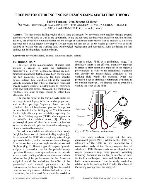
FREE PISTON STIRLING ENGINE DESIGN USING SIMILITUDE THEORYFabien Formosa 1 , Jean-Jacques Chaillout 21 SYMME - Université de Savoie BP 80439- 74944 ANNECY LE VIEUX CEDEX – FRANCE2 LCARE, CEA-LETI-MINATEC, Grenoble, FranceAbstract: The <strong>free</strong> <strong>piston</strong> Stirling <strong>engine</strong> shows some advantages for microminiature machine <strong>design</strong>: externalcombustion, closed cycle as well as the opportunity to use the converse cooling cycle. Based on non-dimensionalanalysis, the effect of the miniaturization for the <strong>design</strong> of such micro-heat <strong>engine</strong>s can be studied. A <strong>similitude</strong>approach for Stirling <strong>engine</strong> is developed. Design charts are then set out so the <strong>engine</strong> parameters can be easilyhandled in relation with the working fluid, technological requirements and constraints. Some guidelines are thenoutlined for Stirling micro machine <strong>design</strong>.Keywords: micro heat <strong>engine</strong>, Stirling, <strong>similitude</strong> <strong>theory</strong>, scalingINTRODUCTIONThe effect of the miniaturization of micro heat<strong>engine</strong>s is crucial to asses the performanceprospective of a given technology. Based on nondimensionalanalysis, turbines have been shown to bethe best promising technology for high specificpower. Indeed, they scaled as 1/L if the maximalvelocity is retained. Nevertheless, their high rotationalspeeds require specific developments to minimizewear and frictional losses. Moreover, the combustionresidence time must be large enough to obtain highefficiency [1-4].The specific power of the Stirling cycle scales as:ω x p mean , in which p mean is the mean charge pressureand ω the operating frequency. Based on thiscriterion, the miniaturization process brings nointrinsic benefit for the Stirling cycle. Yet, it is knownfor its high efficiency and reliability especially for<strong>free</strong> <strong>piston</strong> Stirling <strong>engine</strong>s (FPSE) which appears tobe suitable for miniaturization [5]. From atechnological point of view the external combustionas well as the closed cycle are favourable advantagesof a miniaturized heat <strong>engine</strong>.Second order models are effective tools to studythe global behaviour of classical Stirling <strong>engine</strong>s [6].In the case of the FPSE, the complexity takes thingsup a notch. Indeed, in this case no mechanical linkagefixes the strokes and phase angle for the <strong>piston</strong> anddisplacer (Fig. 1). Hence, a global complex dynamicanalysis is required to predict the periodic steadyoperation. However, these approaches can not providean easy understanding of the main phenomena whichinfluence the global performances. In this frame, ananalytical model that underlines the effect of thegeometrical and thermal parameters on theperformances has been developed [7], but this modelrelies on set of parameters defined beforehand. As aconclusion, there is a need for a simplified model to<strong>design</strong> a micro FPSE at a preliminary stage. The<strong>similitude</strong> <strong>theory</strong> is an efficient alternative approachto effective prior <strong>design</strong> and appraisal of the objectiveperformances. It stems on the fundamental equationsthat describe the thermo-fluidic behaviour of theworking fluid within the machine. Organ hasproposed a set of <strong>similitude</strong> parameters dedicated tothe Stirling <strong>engine</strong> [8]. We propose here to extend thiswork to the study of the FPSE.Buffer spacesRegeneratorDisplacerABFig. 1: FPSE schematic architecture.ABPistonCoolerHeaterFirst, scale analysis brings out the nondimensionalgroups (NDG) related to the FPSE. Therelevance of the NDG is then supported by acomparative study of ten Stirling <strong>engine</strong>s, four ofwhich are FPSE. Design charts are developed so the<strong>engine</strong> parameters (e.g. mean pressure, operatingfrequency, hydraulic radius, length, number of tubesfor the heat exchangers, <strong>piston</strong> and displacer masses,buffer spaces volumes…) can be easily handled inrelation with the working fluid. Finally, the effects ofthe scaling down process are analyzed.A-AB-B0-9743611-5-1/PMEMS2009/$20©2009TRF 562PowerMEMS 2009, Washington DC, USA, December 1-4, 2009
NF pp = A p p meanm p ω 2 L(14)It is worthy of note that the essential role of thedissipative effect from the pressure drop is handled bythe DG Re group. Indeed, the friction factor is related tothe Reynolds number and the geometrical aspect ofthe exchangers both being kept constant by previousrequirements.DISCUSSIONAnalysis of documented <strong>engine</strong>sIn order to support the approach, the NDG havebeen evaluated for fully documented real <strong>engine</strong>snamely: GPU-3, PD46, V160, MP1002CA, USSP40,400HP, RE-1000, CTPC. The last two of them areFPSE.additional previous choices of the extremetemperatures T e and T c and required power, it ispossible to define the remaining parameters. Based onthe set of NDG for the RE-1000 <strong>engine</strong>, <strong>design</strong>scharts are drawn.The charge pressure and operating frequency canthus be easily handled in relation with the workingfluid (Fig. 5-6).Swept volume [cc]power [W]H2 air He8.6.5.4.3.2.1.8.6.5.4.3.2.1.8.6.5.4.3.2.1.10 -3 (L/r h) 3/2100P407050CTPCPD4630V16020RE100015GPU310MP100210 15 20 30 50 70Fig. 3: NTU group for the regenerator.400 HP10 -3 pω μFigure 3 shows that the chosen NDG NTx (see Eq10) is indicative. For the particular case of FPSE, thedynamic groups NF pd and NF pp (Eq. 13-14) areevaluated with two more FPSE <strong>engine</strong>s: B10 [9] andDFPSE [10].500400300200100p AV sw mB10<strong>piston</strong>RE1000DFPSECTPCdisplacer20 40 60 80Fig. 4: Dynamic groups for <strong>piston</strong> and displacer..1000800600400200f [Hz]Again, it appears that the dynamic characteristicsof FPSE can defined with respect to a given nondimensional parameter.Design charts for scaled <strong>engine</strong>sWe postulate that the swept volume V sw isrepresentative of the Stirling <strong>engine</strong> size. With the10.1.0.110.1.0.1Fig. 5: Example data plot.Linear scalefactor = 1/10Figure 5 shows the evaluation of the meanpressure of the <strong>engine</strong> with given swept volume andpower. As the pressure increases higher power can beproduced by the <strong>engine</strong>. Moreover, the same powercan be reached <strong>using</strong> a lower pressure and a suitableworking fluid. These results are in agreement with theclassical literature of Stirling <strong>engine</strong>s.10.1.0.1power [W]10.1.0.10.01Swept volume [cc]Fig. 6: Example data plot.20.30.40.50.60.80.100.120.140.pressure [MPa]H2 air Hefrequency [Hz]20.30.40.50.60.80.100.120.140.20.30.40.50.60.80.100.120.140.Figure 6 shows the evaluation of the operatingfrequency. Once again, the classical result that asmaller size is balanced by a higher frequency isobtained. The numerical evaluation of the relation can564
e useful for preliminary <strong>design</strong> regardingtechnological constraints. Contrary to a geometricalscaling, it can be seen in Fig. 7 that the smaller thesize of the <strong>engine</strong>, the higher are the relative movingparts masses with respect to the whole mass of the<strong>engine</strong>.CONCLUSIONA simple preliminary FPSE <strong>design</strong> method hasbeen developed. Scaling effect on the Stirling <strong>engine</strong>parameters can be studied. Moreover, additionalconstraints such as maximum pressure or powerrequirements can be added to easily validate asuggested <strong>design</strong>. The preliminary defined <strong>engine</strong>parameters can then be used in a refined model tooptimize the <strong>design</strong>.REFERENCES[1] N. Müller and L.G. Fréchette, Performanceanalysis of Brayton and Rankine cycle Microsystemsfor portable power generation, Pro. IMECE2002,November 17-22 2002, New Orleans, Louisiana.[2] S. Tanaka, K. Hikichi1, S. Togo and al.,World’s smallest gas turbine establishing Braytoncycle, Proc. PowerMEMS 2007, Nov 28 - 29,Freiburg, Germany, pp. 359-362.[3] J. Peirs, D. Reynaerts and F. Verplaetsen, Amicroturbine for electric power generation, Sensorsand Actuators A: Physical, Vol. 113 (1) (2004), pp.86-93.Airm [g]HeH21000100[4] F.X. Nicoul, J. Guidez, O. Dessornes, Y.Ribaud, Two stage ultra micro turbine:thermodynamic and performance study, Proc.PowerMEMS 2007, Nov 28 - 29, Freiburg, Germany,pp. 301-304.[5] L. Bowman, D.M. Berchowitz and al.,Microminiature Stirling cycle cryocoolers and<strong>engine</strong>s, US Patent 05749226 (1994).[6] Y. Timoumi, I. Tlili, S. Ben Nasrallah, Designand performance optimization of GPU-3 Stirling<strong>engine</strong>s, Energy 33 7 (2008), pp. 1100-1114.[7] F. Formosa, J.J. Chaillout and O. Dessornes,Size effects on Stirling cycle micro <strong>engine</strong>, Proc.PowerMEMS 2008, 9-12 November 2008 Sendai,Japan, pp. 105-108.[8] A.J. Organ, The Regenerator and the StirlingEngine, Mechanical Engineering Publications,London, (1997).[9] J. G. M. Saturno, Some mathematical modelsto describe the dynamic behavior of the B-10 FPSE,PhD thesis of The Faculty of the Russ College ofEngineering and Technology Ohio University,London, (1994).[10] J. Boucher, F. Lanzetta, P. Nika, Optimizationof a dual <strong>free</strong> <strong>piston</strong> Stirling <strong>engine</strong>, Applied ThermalEngineering 27 (2007), pp. 802–811).displacer <strong>piston</strong>101initial <strong>design</strong>0.1Fig. 7: Example data plot.geometric scaling0.1 110100 V sw [cc]1/10.45 1/4.851/2.25 1/1.04 scale [-]565


