Patrick - Hydrotechnik
Patrick - Hydrotechnik
Patrick - Hydrotechnik
- No tags were found...

Create successful ePaper yourself
Turn your PDF publications into a flip-book with our unique Google optimized e-Paper software.
<strong>Patrick</strong> the Particle CounterOperating Instructions<strong>Patrick</strong>... the Particle CounterOperating InstructionsRev. 1.10 EN • October 28, 2013TKZ L3160-00-76.00EN© <strong>Hydrotechnik</strong> GmbH • All rights reservedRev. 1.10 / 2013-10-28 • L3160-00-76.00ENPage 1 of 21
<strong>Patrick</strong> the Particle CounterOperating InstructionsContents1. Safety .................................................................................................................. 31.1. General Safety and Warning Hints ...................................................................... 31.2. Laser Safety Advice............................................................................................. 31.3. Hints for the Use of the Particle Counter............................................................. 42. Introduction........................................................................................................ 42.1. Range of Validity.................................................................................................. 42.2. Copyright.............................................................................................................. 42.3. Limitation of Liability ............................................................................................ 52.4. Use as Agreed ..................................................................................................... 52.5. Warranty Regulations .......................................................................................... 52.6. Obligations to the Customer ................................................................................ 62.7. Authorized Staff ................................................................................................... 63. Description of the Device.................................................................................. 63.1. Qualities............................................................................................................... 63.2. Components of the Device .................................................................................. 73.3. Technical Data..................................................................................................... 83.4. Dimensional Drawing........................................................................................... 94. Installation and Start-up.................................................................................... 94.1. Installation Location ............................................................................................. 94.2. Installation.......................................................................................................... 104.3. Elektrical Connection ......................................................................................... 114.4. Switching output ................................................................................................ 124.5. Calibration (reference value of the current output)............................................ 124.6. Sequential Data Output ..................................................................................... 134.7. Start-up .............................................................................................................. 135. Operation of the Particle Counter .................................................................. 135.1. Navigation in the Menu...................................................................................... 135.2. Menu Tree ......................................................................................................... 145.2.1. Select operation mode.................................................................................................... 155.2.2. Set alarms....................................................................................................................... 155.2.3. Analog settings ............................................................................................................... 165.2.4. Select standard............................................................................................................... 165.2.5. Flow settings...................................................................................................................165.2.6. Communication settings.................................................................................................. 165.2.7. Display settings............................................................................................................... 175.2.8. Sensor parameter ........................................................................................................... 175.2.9. Language........................................................................................................................176. Communication settings................................................................................. 186.1. Serial interface configuration ............................................................................. 186.1.1. Interface parameters....................................................................................................... 186.1.2. Command list: read commands ...................................................................................... 186.2. USB communication .......................................................................................... 186.3. CAN ................................................................................................................... 187. Troubleshooting .............................................................................................. 21IllustrationsPic. 1 Functional principle........................................................................................................... 6Pic. 2 Front view ......................................................................................................................... 7Pic. 3 Dimensions and mounting possibilities ............................................................................. 9Pic. 4 ∆p-Q-curve for different viscosities ................................................................................. 10Pic. 5 Pin assignment viewed from top to the sensor connector............................................... 11Pic. 6 Measurement of the analog 4 … 20 mA output without load resistor.............................. 11Pic. 7 Measurement of the analog 4 … 20 mA output with load resistor................................... 11Pic. 8 Switching output ............................................................................................................. 12Pic. 9 Sequence when transmitting all parameters subsequently............................................. 13© <strong>Hydrotechnik</strong> GmbH • All rights reservedRev. 1.10 / 2013-10-28 • L3160-00-76.00ENPage 2 of 21
<strong>Patrick</strong> the Particle CounterOperating Instructions1. Safety1.1. General Safety and Warning HintsATTENTION – Dangerous electrical voltage• Do not cut, damage or modify the connection wire and do not place items on it.• Never touch the device with wet or moist hands.• Only connect the device to suited power sources (see technical data).• Unplug the mains cord during a thunderstorm.• Unplug the mains cord when detecting a smell or smoke, or if the cord isdamaged.• Assure a proper grounding of your plant. Measuring errors may be caused byimproper grounding.1.2. Laser Safety AdviceWARNING – Class 1 laser contained• Never remove covers or housings. Otherwise laser light may come out what canlead to injuries of your eyes.• The device contains a laser sensor classified as “Class 1 Product” acc. to 21 CFR,sub-chapter J, of the Health and Safety Act of 1968, when it is used as describedin this manual. This manual does not contain information on implemented parts,maintenance and repair may only be executed by qualified personnel.• This device has been evaluated and tested according to EN61010-1:1993, IEC825-1:1993 and other norms (e.g. ISO 4406, ISO 6149-2).• A label indicating the laser class according to 21 CFR is attached to the device.This must be present and readable at all time. Damaged or unreadable labelsmust be replaced immediately.© <strong>Hydrotechnik</strong> GmbH • All rights reservedRev. 1.10 / 2013-10-28 • L3160-00-76.00ENPage 3 of 21
<strong>Patrick</strong> the Particle CounterOperating Instructions1.3. Hints for the Use of the Particle CounterHandle the device carefully• Never expose the device to excessive heat or moisture, obtain the technical data.• Do not store the device a humid or dusty location or at temperature below thefreezing point.• Never dip the device into water or other liquids. Never let liquid come into thedevice.• Never open the device.• Do not use the device after it has fallen down or if the casing is damaged.• Avoid strong magnetic fields. Keep the device away from electric motos or otherdevices that generate electro-magnetic fields. These may cause malfunctions andinfluence measured values.• Avoid the condensation of water. If water has condensed, you should acclimatethe device before switching it on. Otherwise it may be damaged.2. IntroductionDo not loose claimsThe information and hints in this section are important. By non-observance youmay loose possible warranty claims.2.1. Range of ValidityThe manual on hand is valid for particle counters named "<strong>Patrick</strong>". It adresses to the operator of thisinstrument, that means the person, who works with the instrument. The manual is not a technicalmanual. Please contact our service staff for questions, that exceed the contents of this manual.2.2. CopyrightThe device and this manual are protected on copyright. Manufacture without license will beprosecuted by law. All rights reserved on this manual, even the reproduction and/or duplication inany thinkable form, e.g. by photocopying, printing, on any data recording media or translated.Reproduction of this manual is only permitted with a written approval of <strong>Hydrotechnik</strong> GmbH.The technical state by the time of delivery of instrument and manual is decisive, if no otherinformation is given. Technical changes without special announcements are reserved. Earliermanuals are no longer valid.The general conditions of sale and delivery of <strong>Hydrotechnik</strong> GmbH are valid.© <strong>Hydrotechnik</strong> GmbH • All rights reservedRev. 1.10 / 2013-10-28 • L3160-00-76.00ENPage 4 of 21
<strong>Patrick</strong> the Particle CounterOperating Instructions2.3. Limitation of LiabilityWe guarantee the faultless functioning of our product in accordance with our advertising, the productinformation edited by <strong>Hydrotechnik</strong> GmbH and this manual. Further product features are notguaranteed. We take no liability for the economy and faultless function if the product is used for adifferent purpose than that, described in the chapter „Use as agreed“.Compensation claims are generally impossible, except if intention or culpable negligence by<strong>Hydrotechnik</strong> GmbH is proved, or if assured product features are not provided. If the product is usedin environments, for which it is not suited or which do not represent the technical standard, we arenot responsible for the consequences.We are not responsible for damages at installations and systems in the surroundings of the product,which are caused by a fault of the product or an error in this manual.We are not responsible for the violation of patents and/or other rights of third persons outside theFederal Republic of Germany.We are not liable for damages, which result from improper operation according to this manual. Weare not liable for missed profit and for consecuting damages due to non regardance of safety adviceand warning hints. We don’t accept liability for damages which result from the use of accessoireswhich are not delivered and/or approved by <strong>Hydrotechnik</strong> GmbH.The products of <strong>Hydrotechnik</strong> GmbH are designed for a long life. They represent the standard oftechnique and science and were checked on all functions individually before delivery. The electricaland mechanical construction corresponds to the current norms and regulations. <strong>Hydrotechnik</strong> GmbHis doing product and market research for the further development and permanent improvement oftheir products.In case of faults and/or technical trouble please contact the <strong>Hydrotechnik</strong> GmbH service staff. Weassure that suitable measures will be taken immediately. <strong>Hydrotechnik</strong> GmbH guarantee regulationsare valid, which we will send to you on demand.2.4. Use as AgreedThe device <strong>Patrick</strong> is an optical particle monitor that may be used for the monitoring of fluidcleanliness. It works according to the light extinction principle and detects particles and othercontaminants in the fluid. The measured values are calculated into purity classes according toISO4406:99 or SAE AS4059E and then shown on the display.You may read the measuring data via a serial interface and transfer them to a measuring instrumentor a computer. The connection to the fluid system is achieved by two Minimess ® test points of the1620 screw series.Any other use of this device is regarded as improper use. Please contact our service staff if youhave questions or want to use the device for another purpose. We will be always glad to help you.2.5. Warranty RegulationsIn accordance to our warranty regulations we guarantee the condition without defects for thismeasuring instrument for a duration of six months. Wearing parts and storage batteries are exceptedfrom this warranty. The warranty is spoiled if repair work or interventions are executed byunauthorized persons.Within the warranty period we repair damage or defects which are caused by a manufacturing fault.We only accept warranty claims if they are reported to us immediately after their discovery, but latestsix months after delivery. The warranty benefit is by our choice through repair of defective parts orreplacement by intact parts.© <strong>Hydrotechnik</strong> GmbH • All rights reservedRev. 1.10 / 2013-10-28 • L3160-00-76.00ENPage 5 of 21
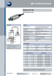
<strong>Patrick</strong> the Particle CounterOperating InstructionsSend your instrument with an invoice copy or delivery note copy to <strong>Hydrotechnik</strong>. The adress ismentioned at the end of this manual.2.6. Obligations to the CustomerThe operating authority of this product has to assure, that only persons who• know the regulations on working safety and accident prevention• have been instructed in the operation of this product• have read and understood this manualcan operate this product. Persons who operate this instrument are obliged to• obey all regulations on working safety and accident prevention• read this manual completely, especially the safety instructions in the first chapter.2.7. Authorized StaffPersons are authorized if they have a professional education, technical experience, knowledge ofthe important norms and regulations and if they are able to estimate their duties and recognizepossible danger at an early time.Operator of the instrumentPersons are authorized if they are trained in the operation of the instrument and have read andunderstood this manual completely.Personell for installation and maintenancePersons are authorized if they are trained in all aspects of the instrument and have read andunderstood this manual completely.3. Description of the Device3.1. QualitiesThe device <strong>Patrick</strong> is an optical particle monitor working according to the light-extinction principle:Pic. 1Functional principleThe device comprises a through-flown measuring cell (A), a laser (B) and a photo cell (C). The lasershines through the measuring cell and impacts the photo cell. If a particle flows through the laserbeam, the intensity reflected by the photo cell is reduced. The larger the particle, the more thereflection will be reduced.© <strong>Hydrotechnik</strong> GmbH • All rights reservedRev. 1.10 / 2013-10-28 • L3160-00-76.00ENPage 6 of 21
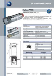
<strong>Patrick</strong> the Particle CounterOperating InstructionsYou may use <strong>Patrick</strong> to monitor the contamination level and the purity trend of fluids. There may bedifferences in the absolute accuracy to particle counters calibrated according to ISO 11171:99, butthis difference is smaller than one ordinal number. Changes are display with very high accuracy. Bythe continuous purity monitoring you can detect changes within a machine very quickly. This allowsyou to initiate measures to avoid further contaminations and damage to the machine.The purity class display can be switched to ISO4406:99 or SAE AS4059E. The device alsomeasures the temperature, not in the liquid but on the electronic switchboard (measuring range -20… 100 °C). The device is equipped with an operating counter, the values will still be available after apower loss. After each interruption, the counter will restart at the last saved time value before theinterruption.Online measurement with a computerAfter connecting <strong>Patrick</strong> to a computer you may use the <strong>Hydrotechnik</strong> software HYDROcom 6 todisplay and record the current measuring values at a PC. Please see the online help of HYDROcom6 for more information.3.2. Components of the Device12 3 4 5 6Pic. 2Front view789101 Fluid inlet2 Rotatable panel3 Indicator „Power“4 Indicator „Alarm“5 Display6 Fluid outlet7 Key „Up“8 Key „Escape“9 Key „Enter“10 Key „DownFluid inlet/outlet (1) (6)The device is equipped with two Minimess ® test points of the 1620 screw series. Normally twoMinimess ® hoses will be connected here to connect <strong>Patrick</strong> to the fluid system.Display (2) (5)The front panel may be rotated by 190° to allow a horizontal orientation of the display in anymounting situation. The bw-display shows the last calculated purity classes and the time to the nextmeasurement, or the remaining measuring duration.Indicator „Power“ (3)Operating voltage is present if the indicator is lit green.Indicator “Alarm” (4)This is lit red if an alarm is present. You may program two alarms, please see the information in therespective chapter of this manual.© <strong>Hydrotechnik</strong> GmbH • All rights reservedRev. 1.10 / 2013-10-28 • L3160-00-76.00ENPage 7 of 21
<strong>Patrick</strong> the Particle CounterOperating InstructionsKeys (7) … (10)The complete operation and programming is done with four keys:opens the main menu; moves the highlighting bar upward; increases a valueopens the main menu; moves the highlighting bar down; lowers a valueselects menu items and opens submenus; confirms entries; jumps to the next digitreturns to the higher menu level; leaves the main menu; cancels entries3.3. Technical DataOperating conditionsallowed operation pressure420 bar (dynamic)environmental temperature -20 ... 80 °Chumidity 0 … 95 %Storage conditionsenvironmental temperature -20 ... 85 °Chumidity 0 … 95 %Fluidsallowed fluidsmineral- and esther fluids, polyalfaolefinesfluid temperature -20 ... 80 °Cfluid connectors 2x ¼“ Minimess ® 1620allowed volume flow rate50 … 400 ml/minMoistened materialshigh-grade steel, sapphire, copperSealing materialNBRPower supply9 … 36 V DCPower consumptionmax. 300 mACurrent outputs4 … 20 mAInterfacesRS 232, CANopenAlarm contactpotential-free contactElectrical connector 8-pole plug M12 x 1Measuring range acc. to ISO 4406:99 0 … 24 (ordinal number)Calibrated measuring range10 … 22 (ordinal number)Measuring accuracy± 1.0 (ordinal number)© <strong>Hydrotechnik</strong> GmbH • All rights reservedRev. 1.10 / 2013-10-28 • L3160-00-76.00ENPage 8 of 21
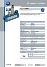
<strong>Patrick</strong> the Particle CounterOperating Instructions3.4. Dimensional DrawingPic. 3Dimensions and mounting possibilitiesA: four mounting points M5 x 5.5B: ventilation hole with pressure compensation elementC: 2x Minimess ® test point 1620, 2103-01-18.00N4. Installation and Start-up4.1. Installation LocationPlease observe these hints when choosing an installation location:• Connect <strong>Patrick</strong> with a T-branch to a bypass pressure line.• The flow direction is arbitrary.• There should be constant pressure conditions at the installation location. The pressure may vary,but there may not be pressure peaks or large alternations.• It is recommended to choose a control line, otherwise you may also choose the filter or coolingloop.• The volume flow rate should be constant between 50 and 400 ml/min.• Flow control or pressure reduction should be installed after the particle counter since suchinstallations may cause particles or air bubbles that may cause wrong measurements.• If a pump is required to produce the required volume flow rate, it should be low-pulsating and beinstalled in front of the particle counter. Otherwise bubbles could be generated on the suctionside what would lead to wrong measurements.© <strong>Hydrotechnik</strong> GmbH • All rights reservedRev. 1.10 / 2013-10-28 • L3160-00-76.00ENPage 9 of 21
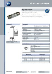
<strong>Patrick</strong> the Particle CounterOperating Instructions4.2. InstallationPlease observe these hints before starting the installation:• Assure that the display can be read easily after installation. It is rotatable by 190° to ease theselection of a installation location.• The shorter, the better is valid for connection hoses. If the hoses get too long, larger particlesmay deposit.• It must be assured especially for higher viscosities and the use of Minimess ® hoses that thepressure is high enough to set a volume flow rate between 50 and 400 ml/min.• Assure a bubble-free fluid. Bubbles in the fluid result in very high ordinal numbers in different sizeclasses. Such bubbles cannot be visible to the naked eye.Estimation of the required pressure levelObtain the deltaP of the particle counter dependant to the fluid viscosity:Pic. 4∆p-Q-curve for different viscositiesThis diagram allows you to estimate the required pressure level for the required volume flow rate of50 to 400 ml/min.InstallationNow you may install <strong>Patrick</strong>:1. Identify the installation location corresponding to the stipulated criteria.2. Connect two fluid lines to the Minimess ® test points.3. Mount the particle counter using the mounting points at the rearside of the device.© <strong>Hydrotechnik</strong> GmbH • All rights reservedRev. 1.10 / 2013-10-28 • L3160-00-76.00ENPage 10 of 21
<strong>Patrick</strong> the Particle CounterOperating Instructions4.3. Elektrical ConnectionThe device may be installed by qualified staff, only. Obtain the national and international regulationsfor the installation of electrical plants and install the power supply in accordance to EN50178, SELV,PELV, VDE0100-410/A1. Use the <strong>Hydrotechnik</strong> power pack 8812-00-00.36 together with theY-distributor 8808-50-01.03.Cut-off the mains power and then connect the device as follows:Pin assignment of sensor connectorPic. 51 +U B2 GND3 TxD; CAN-L4 RxD; CAN-H5 Digital input6 IOUT17 Open Collector, Alarm OUT8 SGNDCasing / shieldPin assignment viewed from top to the sensor connectorThe allowed operating voltage is between 9 and 36 VDC. Use shielded sensor wires, only. You mayonly use suited connectors and wires to achieve protection class IP67. The tightening torque of theconnector is 0.1 Nm.Digital inputThe digital input is „HIGH – active“. It is active when supply voltage is present and “floats” if novoltage is present.A measurement continues while the digital input is NOT connected to ground. When the input isconnected to ground, a current will be present of I = (U – 1.1 V) / 5,600 Ω with U = supply voltage.Analog current outputs (4 ... 20 mA) – Measurement without load resistorPic. 6Measurement of the analog 4 … 20 mA output without load resistorUse a suited measuring instrument, the assignment of the current value to the measurand will beexplained below.Analog current outputs (4 ... 20 mA) – Measurement with load resistorPic. 7Measurement of the analog 4 … 20 mA output with load resistor© <strong>Hydrotechnik</strong> GmbH • All rights reservedRev. 1.10 / 2013-10-28 • L3160-00-76.00ENPage 11 of 21
<strong>Patrick</strong> the Particle CounterOperating InstructionsA load resistor must be connected to each output to measure the current of both analog currentoutputs. Dependant on the supply voltage, the load resistor should be between 250 and 2,600 Ω.Use a volt meter to measure the voltage dropped over the respective resistor.Use the formula shown in section 4.4 on page 12 to calculate the purity class from the measuredvoltages.Calculation of the required load resistorThe load resistor cannot be chosen arbitrary. It must be adapted to the sensor supply voltage. Eitheruse the following formula to calculate the required resistor, or use a value shown in the table:Formula U V in V R max in Ω9 25012 400U − 2VR Max= −100Ω18 60020mA24 1,00030 1,3004.4. Switching outputThe switching output is not short-circuit protected and has no over-current or over-temperatureprotection. The maximum switching voltage is 36 VDC.Pic. 8Switching outputOption 1 Option 2internal external internal externalAlert Ualert Alert Ualert0 = U+ 0 = 01 = 0 1 = U+4.5. Calibration (reference value of the current output)The current range covers ordinal numbers accoring to ISO 4406:99 from 0 … 32. A current value of4 mA corresponds to the ordinal number „Zero“, 20 mA to the ordinal number „26“. The step fromone ordinal number to the next corresponds to a jump of appr. 0.62 mA.© <strong>Hydrotechnik</strong> GmbH • All rights reservedRev. 1.10 / 2013-10-28 • L3160-00-76.00ENPage 12 of 21
<strong>Patrick</strong> the Particle CounterOperating InstructionsFormula I OUT in mA Ordinal No26OZ = × x[] −(20 − 4)[ mA]mA2644 012 1320 264.6. Sequential Data OutputPic. 9Sequence when transmitting all parameters subsequentlyAfter a starting sequence (S), the measured values for the different size classes are transmittedsubsequently. After a pause the next cycle starts with the transmission of the starting sequence.4.7. Start-upThe particle counter will immediately start to measure and will display the first measuring resultsafter approximately one minute.5. Operation of the Particle Counter5.1. Navigation in the MenuThe operation keys are occupied as follows:opens the main menu; moves the highlighting bar upward; increases a valueopens the main menu; moves the highlighting bar down; lowers a valueselects menu items and opens submenus; confirms entries; jumps to the next digitreturns to the higher menu level; leaves the main menu; cancels entries© <strong>Hydrotechnik</strong> GmbH • All rights reservedRev. 1.10 / 2013-10-28 • L3160-00-76.00ENPage 13 of 21
<strong>Patrick</strong> the Particle CounterOperating Instructions5.2. Menu Tree© <strong>Hydrotechnik</strong> GmbH • All rights reservedRev. 1.10 / 2013-10-28 • L3160-00-76.00ENPage 14 of 21
<strong>Patrick</strong> the Particle CounterOperating Instructions5.2.1. Select operation modeObserve the minimal measuring durationDo not use a measuring duration of less than 30 seconds. The particle counterneeds more time to detect all particles accurately. The cleaner the oil, thelonger the measuring duration. ISO 4406:99 purity levels of 15 and bettershould be re-measured after 120 seconds, latest.<strong>Patrick</strong> can be used in three operation modes that can be selected in the menu:Time controlled meas. <strong>Patrick</strong> works with the set sample time and a delay time between themeasurements; example: one minute sample time and four minutesdelay time produce a measuring result each five minutes; in fact this willtake some seconds more, because the laser is re-focussed at thebeginning of each measurement; press again while the option “Timecontrol” is enabled and highlighted to set sample and delay time:Sample time press to start the entry; arrows are displayed at the first digit; pressto set the first digit; press to jump to the next digit; set alldigits of the sample time, confirm with and pressDelay timeset the desired delay time like described for the sample timeDigital I/Othe measurement continues until a signal is present at the input; thedigital input is active when connected with GND; then a current will bepresent of I = (U – 1.1 V) / 5,600 Ω with U = supply voltageButton press the key to start and end a measurementAutomatic<strong>Patrick</strong> continues measuring until sufficient values for statisticallyconfirmed measuring results are available; these will be displayed;measurement starts again after a pause time5.2.2. Set alarmsAlarm typeFirst select the alarm type:Std. AlarmFilter modethe alarm is triggered as soon as a set threshold is exceeded at a channelused to supervise a cleaning; the alarm is triggered after all channels have beenfallen below a defined thresholdPress to activate the desired alarm type and then press again to display the set thresholdvalues:STD. ALARM0 / 0 / 0 / 0Press to start the entry. Arrows will be displayed at the first „Zero“. Press to set the firstalarm threshold. Press to jump to the next class. Repeat this procedure to set the thresholds forall classes. If a class shall be neglected, the value should be set to “Zero”.The thresholds set for the standard alarm will be used for the filter mode, too. And vice versa.© <strong>Hydrotechnik</strong> GmbH • All rights reservedRev. 1.10 / 2013-10-28 • L3160-00-76.00ENPage 15 of 21
<strong>Patrick</strong> the Particle CounterOperating InstructionsAlarm memoryHere you select the reaction of <strong>Patrick</strong> in case of an alarm. This can either be disabled automatically(set to „Auto off“) or remain active until confirmed by the operator.SmoothingHere you may set an average calculation preventing alarms for a single extreme value. Open thefunction and set the desired number of values used to calculate the average.5.2.3. Analog settingsHere you may select which data shall be transferred to the analog output:4 / 6 / 14 / 21 select the class which measured value shall be transferred via the analog output;it is a linear output in full ordinal numbers (4 mA equals to ordinal number “zero”,20 mA to ordinal number “26”); the maximum burden depends on the supplyvoltage (R max = ((U – 2 V) / 20 mA) – 100 Ω)Sequential the measured values of all classes are transferred sequentially (see section 4.6on page 13)5.2.4. Select standardChoose the purity display in accordance to ISO 4406:00 or SAE AS4059E. Please be aware for SAEthat the size classes 38 and 70 µm will not be evaluated in separate channels, but together with sizeclass 21.5.2.5. Flow settings<strong>Patrick</strong> measures the volume flow rate together with particle size and number to calculate theconcentration. This is done when the option „Auto“ is selected (recommended flow rate: 100 ... 400ml/min).Since each measurement has a certain inaccuracy you may set a known volume flow rate. This willbe used to calculate the concentration. Select the option “Fix” and then press , again:Fix050 ml/minPress to start the entry. Arrows will be displayed at the first digit. Press to set the firstdigit. Press to jump to the next digit and repeat the procedure to set the volume flow rate.5.2.6. Communication settingsHere you define the configuration of the digital interface.Select interface typeRS 232CANAutoDetectdata output via the RS 232 interfacedata output via CAN busthe connected recipient will be detected automatically and the data output will beset to the required format© <strong>Hydrotechnik</strong> GmbH • All rights reservedRev. 1.10 / 2013-10-28 • L3160-00-76.00ENPage 16 of 21
<strong>Patrick</strong> the Particle CounterOperating InstructionsBaudrate CANSelect the data transmission speed of the CAN interface. The selected speed must be identic withthat of the connected CAN bus, otherwise communication will be impossible.50 / 125 / … select the speed in kBaudTerm. CAN switches an 120 Ω resistor to terminate the CAN line; this option should be set atany timeNode-ID CANHere you may display the set node ID of the particle counter. This will be required to address theCAN commands and assign the CAN signals correctly.Baudrate RS 232Select the data transmission speed of the RS 232 interface. The selected speed must be identic withthat of your system, otherwise communication will be impossible.Auto TX RS 232Here you may choose the data that shall be transmitted via the digital interface. You may transmitthe current measured values, and the voltage and time values of the particle counter. You maytransmit one, two or all three values.5.2.7. Display settingsAs a standard the display illumination is switched off after ten seconds („Dim after 10x“), but youmay also switch it on permanently („Continuous“).5.2.8. Sensor parameterHere you may view several parameters of the particle counter:Measurement shows the recent measurements of the size classes and a volume flow rateindex; press to toggle the display between the size classesHardware shows several measured values of the system electronics; press to showmore parametersOper. hours shows the number of operation hours of sensor and laserError info shows a list of all error messages and alarms; press to scroll through allinformation messagesFlow adjust shows the volume flow rate level; if the bar is between L and H, the volume flowrate is ok; if the bar fills the complete diagram, or is invisible, and H/L blinks, theflow rate is too high/low and must be adjustedThe display limits (bar chart) are between L = 100 ml/min and H= 400 ml/min.The L (low) starts flashing, if the volume flow rate falls below 100 ml/min. <strong>Patrick</strong>continues measuring correctly down to the minimal flow rate of 50 ml/min.5.2.9. LanguageSelect one of the available languages.© <strong>Hydrotechnik</strong> GmbH • All rights reservedRev. 1.10 / 2013-10-28 • L3160-00-76.00ENPage 17 of 21
<strong>Patrick</strong> the Particle CounterOperating Instructions6. Communication settings6.1. Serial interface configuration<strong>Patrick</strong> can be readout and configured via the serial interface. You will need a PC and an installedterminal software to do this.Connect <strong>Patrick</strong> to an available COM port of the computer. A suited communication cable for theserial connection between sensor and PC/control can be ordered from <strong>Hydrotechnik</strong>. If the computerdoes not have a COM port, you may use a serial interface card or an USB-serial-converter.6.1.1. Interface parameters• Baud rate: 9600 / 57600• Data bits: 8• Parity: none• Stop bits: 1• Flow control: none6.1.2. Command list: read commandsCmd Meaning Return formatRVal[↵] read current measured values withchecksum (CRC)$Time:%.4f[h];ISO4µm:%i[-];ISO6µm:%i[-];ISO14µm:%i[-];ISO21µm:%i[-];SAE4µm:%i[-];SAE6µm:%i[-];SAE14µm:%i[-];SAE21µm:%i[-];Conc4µm:%.2f[p/ml];Conc6µm:%.2f[p/ml];Conc14µm:%.2f[p/ml];Conc21µm:%.2f[p/ml];FIndex:%i[-];Mtime:%i[s];Status:0x0000; 0x0000;0x0000;0x0000;CRC:xRMemS[CR] read number of recordable data MemS: xxxx[CR][LF]setsRMemU[CR] read number of recorded data sets MemU: xxxx[CR][LF]RMem[↵] read all recorded measured values Time [h]; T [°C]; P [-];P40 [-];PTG [1/K];… [CR][LF]x.xxx;x.xxxx;x.xxxx;x.xxxx; x.xxxx;... [CR][LF]RID[↵]read identification with checksum(CRC)<strong>Hydrotechnik</strong>;<strong>Patrick</strong>;SN:xxxxxx-xxx;SW:xx.xx.xx;CRC:x 1)RCon[↵] read current configuration Smode:%i;Fmode:%i;Analog:%i;Amode:%i;Alarm4:%i;Alarm6:%i;Alarm14:%i;Alarm21:%i;(Mtime:%i[s];Htime:%i[s])Please contact our customer support if you need a complete list with all commands.6.2. USB communication6.3. CAN<strong>Patrick</strong> can be readout via an USB interface. You will need a PC with the installed softwareHYDROcom 6. Connect <strong>Patrick</strong> to an USB interface of your computer. A suited RS 232 – USBconverter cable is available from <strong>Hydrotechnik</strong>. Please obtain the hints in the HYDROcom 6 onlinehelp for more information.<strong>Patrick</strong> can be embedded into existing bus systems that comply with the CANopen standard. Pleaserefer to corresponding technical or school books for more information on CAN and CANopen.CANopen Object DictionaryThe table contains the communication-related part of the object dictionary of the particle counter.With a few exceptions, the possible settings correspond to the CANopen standard as described in„DS-301“.© <strong>Hydrotechnik</strong> GmbH • All rights reservedRev. 1.10 / 2013-10-28 • L3160-00-76.00ENPage 18 of 21
<strong>Patrick</strong> the Particle CounterOperating InstructionsCommunication profileIdx SIdx Name Type Attr. Standard Remarks1000h 0 device type unsigned 32 ro 194h sensor, see DS4041001h 0 error list unsigned 8 ro 00h obligatory, see DS3011017h 0 heartbeat time unsigned 16 rw 1388h heartbeat time in ms, range: 0 ... 655351018h identity object record ro0 number of entries unsigned 8 ro 04h largest sub index1 manufacturer ID unsigned 32 ro 000001C0h 000001C0h2 product code unsigned 32 ro 12D5C74Ch 12D5C74Ch3 version number unsigned 32 ro 1000 device specific4 serial number unsigned 32 ro device specific1800h transmit PDO1 parameters record0 number of entries unsigned 8 ro 05h largest sub index1 COB-ID unsigned 32 rw 180h+NodeIDCOB-ID used by PDO, range: 181h ... 1FFh, maybe changed when switched off (bit 30 must beset always, means no TPDO triggered to RTR)2 transmission type unsigned 8 rw FFh cyclic + synchronous, asynchronous;values: 1 … 240, 254, 2555 event timing unsigned 16 rw 1F4h event time in ms for asynchronous TPDO1, valuemust be multiple of 50 and max 127001801h transmit PDO2 parameters record0 number of entries unsigned 8 ro 05h largest sub index1 COB-ID unsigned 32 rw 280h+NodeIDCOB-ID used by PDO, range: 281h … 2FFh,may be changed when switched off (bit 30 mustbe set always, means no TPDO triggered toRTR)2 transmission type unsigned 8 rw FFh cyclic + synchronous, asynchronous;values: 1 … 240, 254, 2555 event timing unsigned 16 rw 1F4h event time in ms for asynchronous TPDO2range: 0 ... 650001802h transmit PDO3 parameters record0 number of entries unsigned 8 ro 05h largest sub index1 COB-ID unsigned 32 rw 380h+NodeIDCOB-ID used by PDO, range: 381h … 3FFh,may be changed when switched off (bit 30 mustbe set always, means no TPDO triggered toRTR)2 transmission type unsigned 8 rw FFh cyclic + synchronous, asynchronous;values: 1 … 240, 254, 2555 event timing unsigned 16 rw 1F4h event time in ms for asynchronous TPDO3range: 0 ... 650001A00h TPDO1 mapping parameters record0 number of entries unsigned 8 ro 05h largest sub index1 PDO mapping for first application object tobe mapped2 PDO mapping for second application objectto be mapped3 PDO mapping for third application object tobe mapped4 PDO mapping for fourth application object tobe mapped5 PDO mapping for fifth application object tobe mapped1A01h TPDO2 mapping parameters recordunsigned 32 co 20000220h operation hours time stamp of measurement,4 byteunsigned 32 co 20010108h ISO4µm, 1 byte in 2001h, sub 01unsigned 32 co 20010208h ISO6µm, 1 Byte im 2001h, sub 02unsigned 33 co 20010308h ISO14µm, 1 Byte im 2001h, sub 03unsigned 32 co 20010408h ISO21µm, 1 Byte im 2001h, sub 040 number of entries unsigned 8 ro 05h largest sub index1 PDO mapping for first application object tobe mapped2 PDO mapping for second application objectto be mapped3 PDO mapping for third application object tobe mapped4 PDO mapping for fourth application object tobe mappedunsigned 32 co 20000220h operation hours time stamp of measurement,4 byteunsigned 32 co 20020108h SAE4µm, 1 byte in 2002h, sub 01unsigned 32 co 20020208h SAE6µm, 1 byte in 2002h, sub 02unsigned 33 co 20020308h SAE14µm, 1 byte in 2002h, sub 03© <strong>Hydrotechnik</strong> GmbH • All rights reservedRev. 1.10 / 2013-10-28 • L3160-00-76.00ENPage 19 of 21
<strong>Patrick</strong> the Particle CounterOperating Instructions5 PDO mapping for fifth application object tobe mapped1A02h TPDO3 mapping parameters record2000h2001h2002h2003hunsigned 32 co 20020408h SAE21µm, 1 byte in 2002h, sub 040 number of entries unsigned 8 ro 05h largest sub index1 PDO mapping for first application object tobe mapped2 PDO mapping for second application objectto be mapped3 PDO mapping for third application object tobe mapped4 PDO mapping for fourth application object tobe mapped5 PDO mapping for fifth application object tobe mappedtime related sensor parametersunsigned 32 co 20000120h operation hours time stamp of measurement,4 byteunsigned 32 co 20030108h oil condition bits, 1 byteunsigned 32 co 20030708h measuring bits, 1 byteunsigned 32 co 20030808h sensor status bits, 1 byteunsigned 32 co 20040008h temperature, 1 byterecord0 number of entries unsigned 8 ro 02h largest sub index1 operation hours counter 1 unsigned 32 ro sensor operation time in seconds2 operation hour time stamp of measurement 1 unsigned 32 ro time stamp of last measurementISO measurementrecord0 number of entries unsigned 8 ro 04h largest sub index1 ISO4µm 1 unsigned 8 ro2 ISO6µm 1 unsigned 8 ro3 ISO14µm 1 unsigned 8 ro4 ISO21µm 1 unsigned 8 roSAE measurementrecord0 number of entries unsigned 8 ro 04h largest sub index1 SAE4µm 1 unsigned 8 ro2 SAE6µm 1 unsigned 8 ro3 SAE14µm 1 unsigned 8 ro4 SAE21µm 1 unsigned 8 rocondition monitoring bit fieldarray0 number of entries unsigned 8 ro 08h largest sub indexoffset of two to display 000, 00 and 0, valid for allclasses:0 = SAE 0001 = SAE 002 = SAE 03 = SAE 14 = SAE 2 …1 oil-specific bits 1 unsigned 8 ro 0 = conc.limit exceeded (C >= ISO 23)1 = high flow rate (F > 400)2 = low flow rate (F < 50)3 = measured values not plausible (air ...)ISO (i+1) >= ISO(i)2 reserved unsigned 8 ro3 reserved unsigned 8 ro4 reserved unsigned 8 ro5 reserved unsigned 8 ro6 reserved unsigned 8 ro7 measurement information 1 unsigned 8 ro 0 = measurement in progress1 = auto measuring mode2 = I/O measuring mode3 = manual measuring mode4 = alarm mode filter / standard8 sensor alarm 1 unsigned 8 ro 0 = laser voltage high (I > 2,8 mA)1 = laser voltage low (I < 1 mA)2 = photo voltage high (U > 4V)3 = photo voltage low (U < 4V)4 = temperature high (T > 80°C)5 = temperature low (T < -20°C)2004h 0 sensor temperature 1 signed 8 ro oil temperature in °C2005h 0 flow rate index unsigned 16 ro flow rate index (0 … 400)2020h command unsigned 8 wo 1 = start measurement2 = stop measurement© <strong>Hydrotechnik</strong> GmbH • All rights reservedRev. 1.10 / 2013-10-28 • L3160-00-76.00ENPage 20 of 21
<strong>Patrick</strong> the Particle CounterOperating Instructions2030h2031h2100hmeasurement settingsrecord0 number of entries unsigned 8 ro 2h largest sub index1 measuring time unsigned 32 rw measuring time in s2 idle time unsigned 32 rw time between two measurementsstart settingsrecord0 number of entries unsigned 8 ro 1h largest sub index1 start mode unsigned 16 rw 0h 0 = network with NMT master (Init => PreOp =>Start_Remote_Node => operational)>0 = network without NMT master (Init =>operational)control functions read memoryrecord0 number of entries unsigned 8 ro 3h largest sub index1 history memory size unsigned 32 ro devicespecificmemory size in data sets2 used history memory unsigned 32 ro occupied data sets in memory (corresponds tothe write pointer internally)3 read pointer, data set unsigned 32 rw auto-incremental read pointer to a data set toread history memory; between 0 and the currentwrite pointer2101h 0 read memory starts segemented SDO dataupload1: mapped on PDOunsigned 16 ro suited pointer must be set before reading (with2100sub3), data set size returned after reading,this initiates a standardized "segmented SDOupload"; obtain: change toggle bit at each dataset and set corresponding bit at end of completetransmission7. TroubleshootingNo communication at COM port or current outputs < 4 mAcable not connected properlyconenct supply and communication cords properlyoperation voltage outside rangerun sensor in the range 9 … 36 VDCNo serial communicationfaulty interface configuration check whether interface parameters (9600, 8,1, N, N)are set correctly in <strong>Patrick</strong> and PCwrong COM portcheck and correct the COM portfaulty notation of sensor commands check notation, obtain small and capital lettersNumLock key disabledenable the NumLock keywrong or defective cableonly use <strong>Hydrotechnik</strong> cablesIdentic values in all size classesair in the oilconnect <strong>Patrick</strong> at pressure side; increase distance tothe pumpFault measurement of analog current outputswrong parameter emittedcorrect the value assignments to the current outputsLaser voltage high / photo voltage lowair in the oilconnect <strong>Patrick</strong> at pressure side; increase distance tothe pumpmeasuring cell dirtyclean the particle counter with clean oil or solvent,e.g. isopropanole© <strong>Hydrotechnik</strong> GmbH • All rights reservedRev. 1.10 / 2013-10-28 • L3160-00-76.00ENPage 21 of 21