Bridon - Teyseer Group
Bridon - Teyseer Group
Bridon - Teyseer Group

You also want an ePaper? Increase the reach of your titles
YUMPU automatically turns print PDFs into web optimized ePapers that Google loves.
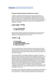
Technical InformationFleet AngleOf all the factors that have some influence on the winding ofa rope on a smooth drum, the fleet angle, arguably, has thegreatest effect.Fleet angle is usually defined as the included angle betweentwo lines, one that extends from a fixed sheave to the flange ofa drum and the other that extends from the same fixed sheaveto the drum in a line perpendicular to the axis of the drum.(See illustration.)Illustration of Fleet AngleAt the sheaveWhere a fleet angle exists as the rope enters a sheave, it initially makescontact with the sheave flange. As the rope continues to pass throughthe sheave, it moves down the flange until it sits in the bottom of thegroove. In doing so, even when under tension, the rope will actually rollas well as slide. As a result of the rolling action, the rope is twisted, i.e.,turn is induced into or out of the rope, either shortening or lengtheningthe lay length of the outer layer of strands. As the fleet angle increasesso does the amount of twist.To reduce the amount of twist to an acceptable level, the fleet angleshould be limited to 2.5° for grooved drums and 1.5° for plain drums,and when using rotation-resistant ropes, the fleet angle should belimited to 1.5°.Fleet angleSheaveHowever, for some crane and hoist applications it is recognizedthat for practical reasons it is not always possible to comply withthese general recommendations, in which case the rope life couldbe affected.DrumIf the drum incorporates helical grooving, the helix angle of thegroove needs to be added or subtracted from the fleet angle asdescribed above to determine the actual fleet angle experiencedby the rope.At the drumWhen spooling rope onto a drum, it is generally recommendedthat the fleet angle is limited to between 0.5° and 2.5°. If the fleetangle is too small, i.e., less than 0.5°, the rope will tend to pileup at the drum flange and fail to return across the drum. In thissituation, the problem may be alleviated by introducing a kickerdevice or by increasing the fleet angle through the introductionof a sheave or spooling mechanism.If the rope is allowed to pile up, it will eventually roll awayfrom the flange, creating a shock load in both the rope andthe structure of the mechanism; an undesirable and unsafeoperating condition.Excessively high fleet angles will return the rope across thedrum prematurely, creating gaps between wraps of rope closeto the flanges as well as increasing the pressure on the rope atthe crossover positions.Even where helical grooving is provided, large fleet angles willinevitably result in localized areas of mechanical damage asthe wires "pluck" against each other. This is often referred to as"interference," but the amount can be reduced by selecting aLangs lay rope if the reeving allows. The interference effect canalso be reduced by employing a Dyform rope, which offers amuch smoother exterior surface than conventionalrope constructions.Floating sheaves or specially designed fleet anglecompensating devices may also be employed to reduce thefleet angle effect.44 BRIDON North American CatalogRope TorqueThe problem of torsional instability in crane hoist ropes would not existif the ropes could be perfectly torque balanced under load. The torquegenerated in a wire rope under load is usually directly related to theapplied load by a constant torque factor. For a given rope construction,the torque factor can be expressed as a proportion of the ropediameter and this has been done below.Variation with rope construction is relatively small, and hence thescope for dramatically changing the stability of a hoisting systemis limited. Nevertheless the choice of the correct rope can have adeciding influence, especially in systems that are operating close tothe critical limit. It should be noted that the rope torque referred tohere is purely that due to tensile loading. No account is taken of thepossible residual torque due, for example, to rope manufacture orinstallation procedures.Torsional StabilityTorsional stability and the cabling graph (see page 46) are twomethods that can be used to determine torsional stability or thetendency of the rope to cable. The torque factors quoted on page 47are approximate maximum values for the particular constructions. Tocalculate the torque value for a particular rope size multiply by thenominal rope diameter. Example: for 20 mm dia. Dyform 34LR at 20%of minimum breaking forceTorque value= torque factor x rope dia.= 0.76% x 20 mm= 0.152 mmTo calculate the torque generated in a particular rope when subjectedto a tensile load, multiply the load by the torque value and combinethe units.Example: for 20 mm dia. Dyform 34LR at 6000 kgf loadTorque generated= torque value x load= 0.152 . 6000= 912 kgf.mm